EP3944706A1 - Method and apparatus for transmitting physical random access channel signal, and electronic device - Google Patents
Method and apparatus for transmitting physical random access channel signal, and electronic device Download PDFInfo
- Publication number
- EP3944706A1 EP3944706A1 EP20777464.7A EP20777464A EP3944706A1 EP 3944706 A1 EP3944706 A1 EP 3944706A1 EP 20777464 A EP20777464 A EP 20777464A EP 3944706 A1 EP3944706 A1 EP 3944706A1
- Authority
- EP
- European Patent Office
- Prior art keywords
- time period
- valid
- transmissions
- random access
- valid time
- Prior art date
- Legal status (The legal status is an assumption and is not a legal conclusion. Google has not performed a legal analysis and makes no representation as to the accuracy of the status listed.)
- Granted
Links
Images




Classifications
-
- H—ELECTRICITY
- H04—ELECTRIC COMMUNICATION TECHNIQUE
- H04W—WIRELESS COMMUNICATION NETWORKS
- H04W74/00—Wireless channel access
- H04W74/002—Transmission of channel access control information
- H04W74/004—Transmission of channel access control information in the uplink, i.e. towards network
-
- H—ELECTRICITY
- H04—ELECTRIC COMMUNICATION TECHNIQUE
- H04W—WIRELESS COMMUNICATION NETWORKS
- H04W74/00—Wireless channel access
- H04W74/08—Non-scheduled access, e.g. ALOHA
- H04W74/0833—Random access procedures, e.g. with 4-step access
- H04W74/0841—Random access procedures, e.g. with 4-step access with collision treatment
-
- H—ELECTRICITY
- H04—ELECTRIC COMMUNICATION TECHNIQUE
- H04W—WIRELESS COMMUNICATION NETWORKS
- H04W72/00—Local resource management
- H04W72/04—Wireless resource allocation
- H04W72/044—Wireless resource allocation based on the type of the allocated resource
- H04W72/0446—Resources in time domain, e.g. slots or frames
-
- H—ELECTRICITY
- H04—ELECTRIC COMMUNICATION TECHNIQUE
- H04W—WIRELESS COMMUNICATION NETWORKS
- H04W74/00—Wireless channel access
- H04W74/002—Transmission of channel access control information
-
- H—ELECTRICITY
- H04—ELECTRIC COMMUNICATION TECHNIQUE
- H04W—WIRELESS COMMUNICATION NETWORKS
- H04W74/00—Wireless channel access
- H04W74/08—Non-scheduled access, e.g. ALOHA
- H04W74/0833—Random access procedures, e.g. with 4-step access
-
- H—ELECTRICITY
- H04—ELECTRIC COMMUNICATION TECHNIQUE
- H04W—WIRELESS COMMUNICATION NETWORKS
- H04W74/00—Wireless channel access
- H04W74/08—Non-scheduled access, e.g. ALOHA
- H04W74/0866—Non-scheduled access, e.g. ALOHA using a dedicated channel for access
-
- H—ELECTRICITY
- H04—ELECTRIC COMMUNICATION TECHNIQUE
- H04W—WIRELESS COMMUNICATION NETWORKS
- H04W72/00—Local resource management
- H04W72/20—Control channels or signalling for resource management
- H04W72/23—Control channels or signalling for resource management in the downlink direction of a wireless link, i.e. towards a terminal
-
- H—ELECTRICITY
- H04—ELECTRIC COMMUNICATION TECHNIQUE
- H04W—WIRELESS COMMUNICATION NETWORKS
- H04W74/00—Wireless channel access
- H04W74/002—Transmission of channel access control information
- H04W74/006—Transmission of channel access control information in the downlink, i.e. towards the terminal
-
- Y—GENERAL TAGGING OF NEW TECHNOLOGICAL DEVELOPMENTS; GENERAL TAGGING OF CROSS-SECTIONAL TECHNOLOGIES SPANNING OVER SEVERAL SECTIONS OF THE IPC; TECHNICAL SUBJECTS COVERED BY FORMER USPC CROSS-REFERENCE ART COLLECTIONS [XRACs] AND DIGESTS
- Y02—TECHNOLOGIES OR APPLICATIONS FOR MITIGATION OR ADAPTATION AGAINST CLIMATE CHANGE
- Y02D—CLIMATE CHANGE MITIGATION TECHNOLOGIES IN INFORMATION AND COMMUNICATION TECHNOLOGIES [ICT], I.E. INFORMATION AND COMMUNICATION TECHNOLOGIES AIMING AT THE REDUCTION OF THEIR OWN ENERGY USE
- Y02D30/00—Reducing energy consumption in communication networks
- Y02D30/70—Reducing energy consumption in communication networks in wireless communication networks
Definitions
- UE #1 Based on this, if user equipment (User Equipment, UE) #1 expects to perform uplink transmission on a random access occasion (RACH Occasion, RO) #1 of a physical random access channel (Physical Random Access Channel, PRACH), the user equipment needs to perform a CCA operation on a time domain resource before the RO #1.
- the time domain resource before the RO #1 may be used for PRACH transmission of another user equipment UE #0. That is, during the CCA, the UE #1 may detect energy of a PRACH signal transmitted by the UE #0, and the UE #1 may determine the channel to be busy because the energy of the signal is higher than a preset threshold. Consequently, the UE #1 fails to transmit a PRACH signal.
- a time domain resource of a PRACH includes at least one RO.
- a PRACH signal includes a cyclic prefix CP and a time domain sequence of a preamble.
- the truncated number of transmissions corresponds to a valid time period 31, and the valid time period 31 is less than transmission duration 30 of one RO.
- a time period other than the valid time period 31 within the transmission duration 30 of one RO is an idle time period 32.
- the truncated transmission mode can be used to reserve a part of idle time period in the time domain resource of the PRACH, so that the UE can use the idle time period for CCA, to prevent a channel from being falsely determined to be busy, thereby ensuring a normal transmission of the PRACH signal.
- FIG. 15 is a schematic structural diagram of an apparatus for transmitting a physical random access channel signal according to an embodiment of this disclosure.
- the apparatus 200 includes an obtaining module 210 and a transmitting module 220.
- a bus architecture may include any number of interconnected buses and bridges, which are specifically linked together by using various circuits of one or more processors represented by the processor 1501 and a memory represented by the memory 1503.
- the bus architecture may further link various other circuits such as peripheral devices, voltage regulators, and power management circuits, which are all known in the art, and therefore, no further description will be provided herein.
- the bus interface provides an interface.
- the transceiver 1502 may be a plurality of elements, that is, including a transmitter and a receiver, and provide a unit for communicating with various other apparatuses over a transmission medium.
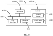
- FIG. 17 is a schematic diagram of a hardware structure of an electronic device performing a method for transmitting a physical random access channel signal according to an embodiment of this disclosure.
- the electronic device may be UE, such as a terminal device of a user.
- the terminal device 1600 shown in the figure includes at least one processor 1601, a memory 1602, a user interface 1604, and at least one network interface 1603.
- Various components in the terminal device 1600 are coupled together by using a bus system 1605.
- the bus system 1605 is configured to implement connection and communication between these components.
- the bus system 1605 further includes a power bus, a control bus, and a status signal bus. However, for the sake of clarity, various buses are marked as the bus system 1605 in the figure.
- the memory 1602 in this embodiment of this disclosure may be a volatile memory or a non-volatile memory, or may include both a volatile memory and a non-volatile memory.
- the non-volatile memory may be a read-only memory (Read-Only Memory, ROM), a programmable read-only memory (Programmable ROM, PROM), an erasable programmable read-only memory (Erasable PROM, EPROM), an electrically erasable programmable read-only memory (Electrically EPROM, EEPROM), or a flash memory.
- the volatile memory may be a random access memory (Random Access Memory, RAM), and is used as an external cache.
- the memory may include a non-permanent memory, a random access memory (RAM) and/or a non-volatile memory, such as a read-only memory (ROM) or a flash memory (flash RAM), in computer-readable media.
- RAM random access memory
- ROM read-only memory
- flash RAM flash memory
- the memory is an example of a computer-readable medium.
Landscapes
- Engineering & Computer Science (AREA)
- Computer Networks & Wireless Communication (AREA)
- Signal Processing (AREA)
- Mobile Radio Communication Systems (AREA)
Abstract
Description
- This disclosure claims priority to
Chinese Patent Application No. 201910223878.4, filed on March 22, 2019 - This disclosure relates to the field of communications technologies, and in particular, to a method and an apparatus for transmitting a physical random access channel signal, and an electronic device.
- On an unlicensed band of new radio (New Radio, NR), before transmitting information, a terminal or a network device needs to perform clear channel assessment (Clear Channel Assessment, CCA) and/or extended clear channel assessment (extended Clear Channel Assessment, eCCA) to listen to a channel, that is, performs energy detection (Energy Detection, ED). When energy is lower than a preset threshold, the channel is determined to be idle, and then transmission can be started. This is LBT (listen before talk). A process for transmission through the above procedure is referred to as a channel access procedure (channel access procedure).
- Based on this, if user equipment (User Equipment, UE) #1 expects to perform uplink transmission on a random access occasion (RACH Occasion, RO) #1 of a physical random access channel (Physical Random Access Channel, PRACH), the user equipment needs to perform a CCA operation on a time domain resource before the RO #1. However, the time domain resource before the RO #1 may be used for PRACH transmission of another user
equipment UE # 0. That is, during the CCA, the UE #1 may detect energy of a PRACH signal transmitted by theUE # 0, and the UE #1 may determine the channel to be busy because the energy of the signal is higher than a preset threshold. Consequently, the UE #1 fails to transmit a PRACH signal. - The information disclosed in the background section is merely intended for a better understanding of the overall background of this disclosure, and the information should be neither expressly or impliedly admitted as the related art already known to persons of ordinary skill in the art.
- An objective of embodiments of this disclosure is to provide a method and an apparatus for transmitting a physical random access channel signal, and an electronic device, so as to avoid a PRACH signal transmission failure due to a channel being falsely determined to be busy.
- To resolve the foregoing technical problem, the embodiments of this disclosure are implemented through the following aspects.
- According to a first aspect, an embodiment of this disclosure provides a method for transmitting a physical random access channel signal, applied to a network device, including: indicating information about a valid time period to user equipment UE, where the valid time period is a part of a time domain resource of a physical random access channel PRACH; and receiving a PRACH signal transmitted by the UE.
- According to a second aspect, an embodiment of this disclosure provides a method for transmitting a physical random access channel signal, applied to user equipment, including: obtaining information about a valid time period, where the valid time period is a part of a time domain resource of a physical random access channel PRACH; and transmitting the PRACH signal within the valid time period.
- According to a third aspect, an embodiment of this disclosure provides an apparatus for transmitting a physical random access channel signal, including: an indication module, configured to indicate information about a valid time period to user equipment UE, where the valid time period is a part of a time domain resource of a physical random access channel PRACH; and a receiving module, configured to receive a PRACH signal transmitted by the UE.
- According to a fourth aspect, an embodiment of this disclosure provides an apparatus for transmitting a physical random access channel signal, including: an obtaining module, configured to obtain information about a valid time period, where the valid time period is a part of a time domain resource of a physical random access channel PRACH; and a transmitting module, configured to transmit the PRACH signal within the valid time period.
- According to a fifth aspect, an embodiment of this disclosure provides an electronic device, including: a memory, a processor, and computer executable instructions stored on the memory and capable of running on the processor, where when the computer executable instructions are executed by the processor, the steps of the method as described in the first aspect are implemented.
- According to a sixth aspect, an embodiment of this disclosure provides an electronic device, including: a memory, a processor, and computer executable instructions stored on the memory and capable of running on the processor, where when the computer executable instructions are executed by the processor, the steps of the method as described in the second aspect are implemented.
- According to a seventh aspect, an embodiment of this disclosure provides a computer-readable storage medium, where the computer-readable storage medium is configured to store computer executable instructions, and when the computer executable instructions are executed by a processor, the steps of the method as described in the first aspect are implemented.
- According to an eighth aspect, an embodiment of this disclosure provides a computer-readable storage medium, where the computer-readable storage medium is configured to store computer executable instructions, and when the computer executable instructions are executed by a processor, the steps of the method as described in the second aspect are implemented.
- According to the method and apparatus for transmitting a physical random access channel signal, and the electronic device that are provided in the embodiments of this disclosure, the information about the valid time period is indicated to the user equipment UE, where the valid time period is a part of the time domain resource of the physical random access channel PRACH; and the PRACH signal transmitted by the UE is received. A part of the time domain resource of the PRACH can be used to transmit the PRACH signal, and therefore a part of the time domain resource of the PRACH is reserved as an idle time period, so that the UE can use the idle time period for CCA, to avoid a PRACH signal transmission failure due to a channel being falsely determined to be busy.
- In order to describe the technical solutions in the embodiments of this disclosure or in the related art more clearly, the accompanying drawings required for describing the embodiments or the related art are briefly described below. Apparently, the accompanying drawings in the following description show only some embodiments recorded in this disclosure, and persons of ordinary skill in the art may still derive other drawings from these accompanying drawings without creative efforts.
-
FIG. 1 is a schematic flowchart of a method for transmitting a physical random access channel signal according to an embodiment of this disclosure; -
FIG. 2 is another schematic flowchart of a method for transmitting a physical random access channel signal according to an embodiment of this disclosure; -
FIG. 3a is a schematic diagram of a method for transmitting a physical random access channel signal according to an embodiment of this disclosure; -
FIG. 3b is a schematic diagram of a method for transmitting a physical random access channel signal according to an embodiment of this disclosure; -
FIG. 4 is a schematic flowchart of a method for transmitting a physical random access channel signal according to an embodiment of this disclosure; -
FIG. 5 is another schematic flowchart of a method for transmitting a physical random access channel signal according to an embodiment of this disclosure; -
FIG. 6 is another schematic flowchart of a method for transmitting a physical random access channel signal according to an embodiment of this disclosure; -
FIG. 7 is another schematic flowchart of a method for transmitting a physical random access channel signal according to an embodiment of this disclosure; -
FIG. 8 is a schematic diagram of a valid RO; -
FIG. 9 is a schematic flowchart of a method for transmitting a physical random access channel signal according to an embodiment of this disclosure; -
FIG. 10 is another schematic flowchart of a method for transmitting a physical random access channel signal according to an embodiment of this disclosure; -
FIG. 11 is another schematic flowchart of a method for transmitting a physical random access channel signal according to an embodiment of this disclosure; -
FIG. 12 is another schematic flowchart of a method for transmitting a physical random access channel signal according to an embodiment of this disclosure; -
FIG. 13 is another schematic flowchart of a method for transmitting a physical random access channel signal according to an embodiment of this disclosure; -
FIG. 14 is a schematic structural diagram of an apparatus for transmitting a physical random access channel signal according to an embodiment of this disclosure; -
FIG. 15 is a schematic structural diagram of an apparatus for transmitting a physical random access channel signal according to an embodiment of this disclosure; -
FIG. 16 is a schematic diagram of a hardware structure of an electronic device performing a method for transmitting a physical random access channel signal according to an embodiment of this disclosure; and -
FIG. 17 is a schematic diagram of a hardware structure of an electronic device performing a method for transmitting a physical random access channel signal according to an embodiment of this disclosure. - To help persons in the art better understand the technical solutions in this disclosure, the technical solutions in the embodiments of this disclosure are clearly and completely described below with reference to the accompanying drawings in the embodiments of this disclosure. Apparently, the described embodiments are only some rather than all of the embodiments of this disclosure. All other embodiments derived by persons of ordinary skill in the art based on the embodiments of this disclosure without creative efforts shall fall within the protection scope of this disclosure.
-
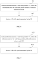
FIG. 1 is a schematic flowchart of a method for transmitting a physical random access channel signal according to an embodiment of this disclosure. The method may be performed by an electronic device, such as a network device. In other words, the method may be performed by software or hardware installed on the network device. As shown in the figure, the method may include the following steps S111 and S112. - Sill: Indicate information about a valid time period to UE.
- The valid time period is a part of a time domain resource of a PRACH.
- The network device may determine a part of the time domain resource of the PRACH as a valid time period, and the other part different from the valid time period is an idle time period.
- In a possible implementation, obtaining information about a valid time period by the UE includes receiving the information about the valid time period that is indicated by the network device.
- S112: Receive a PRACH signal transmitted by the UE.
- The UE transmits the PRACH signal within the valid time period. Specifically, the UE transmits the PRACH signal only within the valid time period. In other words, the UE does not transmit the PRACH signal within the idle time period.
- The network device receives the PRACH signal transmitted by the UE within the valid time period.
- Therefore, according to the method for transmitting a physical random access channel signal provided in this embodiment of this disclosure, the information about the valid time period is indicated to the UE, where the valid time period is a part of the time domain resource of the physical random access channel PRACH; and the PRACH signal transmitted by the UE is received. A part of the time domain resource of the PRACH can be used to transmit the PRACH signal, and a part of the time domain resource of the PRACH is reserved as an idle time period, so that the UE can use the idle time period for CCA, to prevent a channel from being falsely determined to be busy, thereby ensuring a normal transmission of the PRACH signal.
-
FIG. 2 is a schematic flowchart of a method for transmitting a physical random access channel signal according to an embodiment of this disclosure. The method may be performed by an electronic device, such as a network device. In other words, the method may be performed by software or hardware installed on the network device. As shown in the figure, the method may include the following steps S121 and S122. - S121: Indicate information about a valid time period to UE, where the information about the valid time period includes the truncated number of transmissions.
- The truncated number of transmissions is the number of transmissions of a time domain sequence of a random access preamble within one RO, and the truncated number of transmissions is greater than or equal to 1.
-
FIG. 3a is a schematic diagram of a method for transmitting a physical random access channel signal according to an embodiment of this disclosure. As shown in the figure, a time domain resource of a PRACH includes at least one RO. A PRACH signal includes a cyclic prefix CP and a time domain sequence of a preamble. The truncated number of transmissions corresponds to avalid time period 31, and thevalid time period 31 is less thantransmission duration 30 of one RO. A time period other than thevalid time period 31 within thetransmission duration 30 of one RO is anidle time period 32. - In a possible implementation, obtaining information about a valid time period by the UE includes receiving the information about the valid time period that is indicated by the network device.
- S122: Receive a PRACH signal transmitted by the UE.
- The UE transmits the PRACH signal within the valid time period. Specifically, the UE transmits the PRACH signal only within the valid time period. In other words, the UE does not transmit a PRACH signal within the idle time period.
- The network device receives the PRACH signal transmitted by the UE within the valid time period.
- Therefore, according to the method for transmitting a physical random access channel signal provided in this embodiment of this disclosure, the information about the valid time period is indicated to the UE, where the valid time period is a part of the time domain resource of the physical random access channel PRACH; and the PRACH signal transmitted by the UE is received. A part of the time domain resource of the PRACH can be used to transmit the PRACH signal, and a part of the time domain resource of the PRACH is reserved as an idle time period, so that the UE can use the idle time period for CCA, to prevent a channel from being falsely determined to be busy, thereby ensuring a normal transmission of the PRACH signal.
- Moreover, in this embodiment of this disclosure, the truncated number of transmissions is the number of transmissions of a time domain sequence of a random access preamble within one random access occasion RO, the truncated number of transmissions is greater than or equal to 1, and the valid time period is less than transmission duration of the one RO. By means of the truncated number of transmissions, a part of the transmission duration of one RO can be reserved as an idle time period, so that the UE can use the idle time period for CCA, to prevent a channel from being falsely determined to be busy, thereby ensuring a normal transmission of the PRACH signal.
-
FIG. 4 is a schematic flowchart of a method for transmitting a physical random access channel signal according to an embodiment of this disclosure. The method may be performed by an electronic device, such as a network device. In other words, the method may be performed by software or hardware installed on the network device. As shown in the figure, the method may include the following steps S131 and S132. - S131: Indicate information about a valid time period to UE, where the information about the valid time period includes the truncated number of transmissions, and the truncated number of transmissions is less than an initial number of transmissions.
- The truncated number of transmissions is the number of transmissions of a time domain sequence of a random access preamble within one RO, and the truncated number of transmissions is greater than or equal to 1.
- In a possible implementation, the initial number of transmissions is the number of transmissions of the time domain sequence of the preamble corresponding to a specified PRACH format within the one RO, and the initial number of transmissions is greater than 1.
- For example, Table 1 shows a possible specified PRACH format, where a coefficient multiplied by 2048κ·2-µ in the column N u is the initial number of transmissions.
Table 1 Format L RA Δf RA N u 
Support for restricted sets A1 139 15·2 µ kHz 2·2048κ·2 -µ 288κ · 2-µ - A2 139 15·2 µ kHz 4·2048κ·2-µ 576κ · 2-µ - A3 139 15·2 µ kHz 6·2048κ·2-µ 864κ · 2-µ - B1 139 15·2 µ kHz 2·2048κ·2-µ 216κ · 2-µ - B2 139 15·2 µ kHz 4·204κ·2-µ 360κ · 2-µ - B3 139 15·2 µ kHz 6·2048κ·2-µ 504κ·2 -µ - B4 139 15·2 µ kHz 12·2048κ·2-µ 936κ·2-µ - C0 139 15·2 µ kHz 2048κ·2-µ 1240κ·2-µ - C2 139 15·2 µ kHz 4·2048κ·2-µ 2048κ·2 -µ - The truncated number of transmissions is less than an initial number of transmissions. In a possible implementation, a predetermined number of times may be subtracted from the initial number of transmissions, to obtain the truncated number of transmissions. For example, for format A2, the initial number of transmissions is 4, and the truncated number of transmissions is 3. It needs to be ensured that the truncated number of transmissions is greater than or equal to 1, so that the PRACH signal can be completely transmitted. For example, for PRACH format C0 in Table 1, because the initial number of transmissions is 1, if a truncation operation in this step is performed, the complete transmission of the PRACH signal cannot be ensured, and therefore the truncation cannot be performed. The information about the valid time period that is indicated to the UE in this step includes only the truncated number of transmissions, and does not include the initial number of transmissions.
- Table 2 shows a possible implementation of the truncated number of transmissions proposed in this embodiment of this disclosure.
Table 2 Format L RA Δf RA N u 
Support for restricted sets A1s 139 15·2 µ kHz 1·2048κ·2-µ 288 κ · 2-µ - A2s 139 15·2 µ kHz 3·2048κ·2-µ 576 κ · 2-µ - A3s 139 15 · 2 µ kHz 5·2048κ·2 -µ 864 κ · 2-µ - B1s 139 15 · 2 µ kHz 1·2048κ·2-µ 216 κ · 2-µ - B2s 139 15 · 2 µ kHz 3·2048κ·2-µ 360 κ · 2-µ - B3s 139 15 · 2 µ kHz 5 · 2048κ · 2 -µ 504 κ · 2 -µ - B4s 139 15 · 2 µ kHz 11 · 2048κ · 2-µ 936 κ · 2-µ - C2s 139 15 · 2 µ kHz 3 · 2048κ · 2-µ 2048 κ · 2 -µ - A coefficient multiplied by 2048κ·2-µ in the column N u is the truncated number of transmissions. The initial number of transmissions specified in Table 1 minus 1 is used as the truncated number of transmissions. In Table 2, the formats are denoted as formats A1s, A2s, A3s, B1s, B2s, B3s, B4s, and C2s, respectively.
- In a possible implementation, the network device may transmit formats A1, A2, A3, B1, B2, B3, B4, and C2 in Table 1 and formats A1s, A2s, A3s, B1s, B2s, B3s, B4s, and C2s in Table 2 to the UE, and the UE chooses the initial number of transmissions or the truncated number of transmissions.
- In another possible implementation, the truncated number of transmissions may be determined according to a preset truncation goal. For example, the preset truncation goal is to reduce a transmission time by 25 microseconds, so as to reserve a sufficient idle time period for LBT. In this case, a valid time period can be calculated by reducing the transmission time of one RO by 25 microseconds, and the number of repeated transmissions of the time domain sequence of the preamble that can be performed within the valid time period is calculated as the truncated number of transmissions. Similarly, the truncated number of transmissions should be greater than 1 to ensure that the time domain sequence of the preamble can be completely transmitted. In addition, the truncated number of transmissions may not necessarily be an integer number.
- S132: Receive a PRACH signal transmitted by the UE.
- The UE transmits the PRACH signal within the valid time period. Specifically, the UE transmits the PRACH signal only within the valid time period. In other words, the UE does not transmit a PRACH signal within the idle time period.
- The network device receives the PRACH signal transmitted by the UE within the valid time period.
- Therefore, according to the method for transmitting a physical random access channel signal provided in this embodiment of this disclosure, the information about the valid time period is indicated to the UE, where the valid time period is a part of the time domain resource of the physical random access channel PRACH; and the PRACH signal transmitted by the UE is received. A part of the time domain resource of the PRACH can be used to transmit the PRACH signal, and a part of the time domain resource of the PRACH is reserved as an idle time period, so that the UE can use the idle time period for CCA, to prevent a channel from being falsely determined to be busy, thereby ensuring a normal transmission of the PRACH signal.
- Moreover, in this embodiment of this disclosure, the truncated number of transmissions is the number of transmissions of a time domain sequence of a random access preamble within one random access occasion RO, the truncated number of transmissions is greater than or equal to 1, and the valid time period is less than transmission duration of the one RO. By means of the truncated number of transmissions, on the premise that the complete transmission of the preamble is ensured, a part of the transmission duration of one RO can be reserved as an idle time period, so that the UE can use the idle time period for CCA, to prevent a channel from being falsely determined to be busy, thereby ensuring a normal transmission of the PRACH signal.
- Moreover, in this embodiment of this disclosure, the truncated number of transmissions is less than an initial number of transmissions, where the initial number of transmissions is the number of transmissions of the time domain sequence of the preamble corresponding to a specified PRACH format within the one RO, and the initial number of transmissions is greater than 1. In this way, on the premise that the complete transmission of the preamble is ensured, a part of the transmission duration of one RO can be reserved as an idle time period, so that the UE can use the idle time period for CCA, to prevent a channel from being falsely determined to be busy, thereby ensuring a normal transmission of the PRACH signal.
-
FIG. 5 is a schematic flowchart of a method for transmitting a physical random access channel signal according to an embodiment of this disclosure. The method may be performed by an electronic device, such as a network device. In other words, the method may be performed by software or hardware installed on the network device. As shown in the figure, the method may include the following steps S141 and S142. - S141: Indicate information about a valid time period to UE, where the information about the valid time period includes the truncated number of transmissions and a start time of the valid time period.
- In a possible implementation, the information about the valid time period may be indicated to the UE by using higher layer signaling. The UE receives the information about the valid time period that is indicated by the network device.
- The truncated number of transmissions is the number of transmissions of a time domain sequence of a random access preamble within one RO, and the truncated number of transmissions is greater than or equal to 1.
- As shown in
FIG. 3a , a time domain resource of a PRACH includes at least one RO. A PRACH signal includes a cyclic prefix CP and a time domain sequence of a preamble. The truncated number of transmissions corresponds to avalid time period 31, and thevalid time period 31 is less thantransmission duration 30 of one RO. A time period other than thevalid time period 31 within thetransmission duration 30 of one RO is anidle time period 32. -
FIG. 3b is a schematic diagram of a method for transmitting a physical random access channel signal according to an embodiment of this disclosure. As shown in the figure, the start time of the valid time period may be a delay time point P that is delayed by a preset time T relative to a start time TO of the RO, and the UE may start transmitting a PRACH signal from the delay time point P, and transmit a preamble repeatedly and consecutively according to the truncated number of transmissions. Because the valid time period is shorter thantransmission duration 40 of the RO, the number of repeated transmissions of the preamble can be reduced, and the delay time T is used such that an idle time period sufficient to complete LBT can be reserved within thetransmission duration 40 of the RO. - Optionally, the preset time T is less than or equal to a difference between the transmission duration of the RO and the valid time period. In a possible implementation, the preset time may be 25 microseconds (µs).
- S142: Receive a PRACH signal transmitted by the UE.
- The UE transmits the PRACH signal within the valid time period. Specifically, the UE transmits the PRACH signal only within the valid time period. In other words, the UE does not transmit a PRACH signal within the idle time period. The network device receives the PRACH signal transmitted by the UE within the valid time period.
- Therefore, according to the method for transmitting a physical random access channel signal provided in this embodiment of this disclosure, the information about the valid time period is indicated to the UE, where the valid time period is a part of the time domain resource of the physical random access channel PRACH; and the PRACH signal transmitted by the UE is received. A part of the time domain resource of the PRACH can be used to transmit the PRACH signal, and a part of the time domain resource of the PRACH is reserved as an idle time period, so that the UE can use the idle time period for CCA, to prevent a channel from being falsely determined to be busy, thereby ensuring a normal transmission of the PRACH signal.
- Moreover, in this embodiment of this disclosure, the truncated number of transmissions is the number of transmissions of a time domain sequence of a random access preamble within one random access occasion RO, the truncated number of transmissions is greater than or equal to 1, and the valid time period is less than transmission duration of the one RO. By means of the truncated number of transmissions, a part of the transmission duration of one RO can be reserved as an idle time period, so that the UE can use the idle time period for CCA, to prevent a channel from being falsely determined to be busy, thereby ensuring a normal transmission of the PRACH signal.
-
FIG. 6 is another schematic flowchart of a method for transmitting a physical random access channel signal according to an embodiment of this disclosure. The method may be performed by an electronic device, such as a network device. In other words, the method may be performed by software or hardware installed on the network device. As shown in the figure, the method may include the following steps S61 and S62. - S61: Indicate information about a valid time period to UE, where the information about the valid time period includes a truncated transmission mode.
- The network device may indicate the UE to use the truncated transmission mode for transmission. The truncated transmission mode may be a predefined truncated transmission format, such as formats A1s, A2s, A3s, B1s, B2s, B3s, B4s, and C2s shown above in Table 2. In addition, the truncated transmission mode may alternatively be the predefined initial number of transmissions minus the predetermined number of times, for example, minus 1 or 2.
- S62: Receive a PRACH signal transmitted by the UE.
- The UE transmits the PRACH signal in the truncated transmission mode. The network device receives the PRACH signal transmitted by the UE.
- Therefore, according to the method for transmitting a physical random access channel signal provided in this embodiment of this disclosure, the truncated transmission mode can be used to reserve a part of idle time period in the time domain resource of the PRACH, so that the UE can use the idle time period for CCA, to prevent a channel from being falsely determined to be busy, thereby ensuring a normal transmission of the PRACH signal.
-
FIG. 7 is a schematic flowchart of a method for transmitting a physical random access channel signal according to an embodiment of this disclosure. The method may be performed by an electronic device, such as a network device. In other words, the method may be performed by software or hardware installed on the network device. As shown in the figure, the method may include the following steps S151 and S152. - S151: Indicate information about a valid time period to UE, where the information about the valid time period includes information about a valid RO.
- In a possible implementation, obtaining information about a valid time period by the UE includes receiving the information about the valid time period that is indicated by the network device.
- The valid time period is a part of a time domain resource of a PRACH. The time domain resource of the PRACH includes a plurality of ROs, and the valid RO is a part of the plurality of ROs. The other part of the ROs different from the valid RO is an idle RO.
-
FIG. 8 is a schematic diagram of a valid RO. As shown in the figure, in a possible implementation, the valid RO may be an odd- or even-numbered RO in a radio frame and/or slot 71 of a PRACH. - In a possible implementation, the information about the valid RO includes a start time of the valid RO. For example, if an RO #1 is a valid RO, the information about the valid RO includes a start time of the RO #1.
- In a possible implementation, the valid RO may be indicated by using higher layer signaling, for example, a higher layer signaling prach-ConfigurationIndex indication. In another possible implementation, on the basis of the existing higher layer signaling, indication information may be added to indicate the valid RO in ROs indicated by prach-ConfigurationIndex, where the indication information may be higher layer signaling, a MAC-CE, downlink control information, or the like.
- S152: Receive a PRACH signal transmitted by the UE.
- The UE transmits the PRACH signal within the valid RO. Specifically, the UE transmits the PRACH signal only within the valid RO. In other words, the UE does not transmit a PRACH signal within the idle RO.
- The network device receives the PRACH signal transmitted by the UE within the valid RO.
- Therefore, according to the method for transmitting a physical random access channel signal provided in this embodiment of this disclosure, the information about the valid time period is indicated to the UE, where the information about the valid time period includes the information about the valid RO, and the valid time period is a part of the time domain resource of the physical random access channel PRACH; and the PRACH signal transmitted by the UE is received. Some of ROs in the time domain resource of the PRACH can be used to transmit the PRACH signal, and some of the ROs in the time domain resource of the PRACH are reserved as idle ROs, so that the UE can use the idle ROs for CCA, to prevent a channel from being falsely determined to be busy, thereby ensuring a normal transmission of the PRACH signal.
-
FIG. 9 is a schematic flowchart of a method for transmitting a physical random access channel signal according to an embodiment of this disclosure. The method may be performed by an electronic device, such as UE. In other words, the method may be performed by software or hardware installed on the UE. As shown in the figure, the method may include the following steps S211 and S212. - S211: Obtain information about a valid time period.
- In a possible implementation, the UE may obtain the information about the valid time period based on preset information. For example, the Table 2 above may be stored in the UE as the preset information, from which the information about the valid time period is obtained in this step.
- S212: Transmit a PRACH signal within the valid time period.
- The UE transmits the PRACH signal within the valid time period. Specifically, the UE transmits the PRACH signal only within the valid time period. In other words, the UE does not transmit a PRACH signal within an idle time period.
- A network device receives the PRACH signal transmitted by the UE within the valid time period.
- Therefore, according to the method for transmitting a physical random access channel signal provided in this embodiment of this disclosure, the information about the valid time period is obtained, where the valid time period is a part of a time domain resource of a physical random access channel PRACH; and the PRACH signal is transmitted within the valid time period. A part of the time domain resource of the PRACH can be used to transmit the PRACH signal, and a part of the time domain resource of the PRACH is reserved as an idle time period, so that the UE can use the idle time period for CCA, to prevent a channel from being falsely determined to be busy, thereby ensuring a normal transmission of the PRACH signal.
-
FIG. 10 is another schematic flowchart of a method for transmitting a physical random access channel signal according to an embodiment of this disclosure. The method may be performed by an electronic device, such as UE. In other words, the method may be performed by software or hardware installed on the UE. As shown in the figure, the method may include the following steps S221 and S222. - S221: Obtain information about a valid time period, where the information about the valid time period includes the truncated number of transmissions.
- In a possible implementation, the UE may obtain the information about the valid time period based on preset information. For example, the Table 2 above may be stored in the UE as the preset information, from which the information about the valid time period is obtained in this step.
- The information about the valid time period includes a truncated number of transmissions, where the truncated number of transmissions is the number of transmissions of a time domain sequence of a random access preamble within one random access occasion RO, the truncated number of transmissions is greater than or equal to 1, and the valid time period is less than transmission duration of the one RO.
- In a possible implementation, the truncated number of transmissions is less than an initial number of transmissions, where the initial number of transmissions is the number of transmissions of the time domain sequence of the preamble corresponding to a specified PRACH format within the one RO, and the initial number of transmissions is greater than 1.
- In a possible implementation, the information about the valid time period further includes a start time of the valid time period.
- In a possible implementation, the UE may determine the valid time period based on the truncated number of transmissions, and transmit a PRACH signal according to the valid time period in a subsequent step.
- S222: Transmit the PRACH signal within the valid time period.
- The UE transmits the PRACH signal within the valid time period. Specifically, the UE transmits the PRACH signal only within the valid time period. In other words, the UE does not transmit a PRACH signal within the idle time period.
- A network device receives the PRACH signal transmitted by the UE within the valid time period.
- Therefore, according to the method for transmitting a physical random access channel signal provided in this embodiment of this disclosure, a part of a time domain resource of a PRACH can be used to transmit the PRACH signal, and a part of the time domain resource of the PRACH is reserved as an idle time period, so that the UE can use the idle time period for CCA, to prevent a channel from being falsely determined to be busy, thereby ensuring a normal transmission of the PRACH signal.
-
FIG. 11 is another schematic flowchart of a method for transmitting a physical random access channel signal according to an embodiment of this disclosure. The method may be performed by an electronic device, such as UE. In other words, the method may be performed by software or hardware installed on the UE. As shown in the figure, the method may include the following steps S231 and S232. - S231: Obtain information about an valid time period from a network device by using higher layer signaling.
- In a possible implementation, the information about the valid time period is obtained from the network device, for example, by using the higher layer signaling prach-ConfigurationIndex.
- The information about the valid time period includes a truncated number of transmissions, where the truncated number of transmissions is the number of transmissions of a time domain sequence of a random access preamble within one random access occasion RO, the truncated number of transmissions is greater than or equal to 1, and the valid time period is less than transmission duration of the one RO.
- In a possible implementation, the truncated number of transmissions is less than an initial number of transmissions, where the initial number of transmissions is the number of transmissions of the time domain sequence of the preamble corresponding to a specified PRACH format within the one RO, and the initial number of transmissions is greater than 1.
- In a possible implementation, the information about the valid time period further includes a start time of the valid time period.
- S232: Transmit a PRACH signal within the valid time period.
- The UE transmits the PRACH signal within the valid time period. Specifically, the UE transmits the PRACH signal only within the valid time period. In other words, the UE does not transmit a PRACH signal within an idle time period.
- The network device receives the PRACH signal transmitted by the UE within the valid time period.
- Therefore, according to the method for transmitting a physical random access channel signal provided in this embodiment of this disclosure, a part of a time domain resource of a PRACH can be used to transmit the PRACH signal, and a part of the time domain resource of the PRACH is reserved as an idle time period, so that the UE can use the idle time period for CCA, to prevent a channel from being falsely determined to be busy, thereby ensuring a normal transmission of the PRACH signal.
-
FIG. 12 is another schematic flowchart of a method for transmitting a physical random access channel signal according to an embodiment of this disclosure. The method may be performed by an electronic device, such as UE. In other words, the method may be performed by software or hardware installed on the UE. As shown in the figure, the method may include the following steps S241 and S242. - S241: Obtain information about a valid time period, where the information about the valid time period includes information about a valid RO.
- The valid time period is a part of a time domain resource of a PRACH. The time domain resource of the PRACH includes a plurality of ROs, and the valid RO is a part of the plurality of ROs. The other part of the ROs different from the valid RO is an idle RO.
- In a possible implementation, the valid RO may be an odd- or even-numbered RO.
- In a possible implementation, the information about the valid RO includes a start time of the valid RO.
- In a possible implementation, the valid RO may be indicated by using higher layer signaling, for example, a higher layer signaling prach-ConfigurationIndex indication. In another possible implementation, on the basis of the existing higher layer signaling, indication information may be added to indicate the valid RO in ROs indicated by prach-ConfigurationIndex, where the indication information may be higher layer signaling, a MAC-CE, downlink control information, or the like.
- S242: Transmit a PRACH signal within the valid time period.
- The UE transmits the PRACH signal within the valid time period. Specifically, the UE transmits the PRACH signal only within the valid time period. In other words, the UE does not transmit a PRACH signal within an idle time period.
- The network device receives the PRACH signal transmitted by the UE within the valid time period.
- Therefore, according to the method for transmitting a physical random access channel signal provided in this embodiment of this disclosure, some of ROs in the time domain resource of the PRACH can be used to transmit the PRACH signal, and some of the ROs in the time domain resource of the PRACH are reserved as idle ROs, so that the UE can use the idle ROs for CCA, to prevent a channel from being falsely determined to be busy, thereby ensuring a normal transmission of the PRACH signal.
-
FIG. 13 is another schematic flowchart of a method for transmitting a physical random access channel signal according to an embodiment of this disclosure. The method may be performed by an electronic device, such as UE. In other words, the method may be performed by software or hardware installed on the UE. As shown in the figure, the method may include the following steps S251 and S252. - S251: Obtain PRACH control information.
- The PRACH control information is used to limit a transmission time of the PRACH signal to be less than transmission duration of one RO.
- The UE may obtain the PRACH control information from other external devices, such as a network device. The PRACH control information may indicate the UE to use a truncated transmission mode for transmission. The truncated transmission mode may be a predefined truncated transmission format, such as formats A1s, A2s, A3s, B1s, B2s, B3s, B4s, and C2s shown above in Table 2. In addition, the truncated transmission mode may alternatively be a predefined initial number of transmissions minus a predetermined number of times, for example, minus 1 or 2.
- In a possible implementation, the PRACH control information is used to indicate a valid RO for transmitting the PRACH signal. The valid RO is a part of multiple ROs.
- In a possible implementation, the PRACH control information may include: a truncated number of transmissions, where the truncated number of transmissions is the number of transmissions of a time domain sequence of a random access preamble within one random access occasion RO, and the truncated number of transmissions is greater than or equal to 1.
- In a possible implementation, the truncated number of transmissions is less than an initial number of transmissions, where the initial number of transmissions is the number of transmissions of the time domain sequence of the preamble corresponding to a specified PRACH format within the one RO, and the initial number of transmissions is greater than 1.
- In a possible implementation, the PRACH control information further includes a start time of the valid time period. For example, a preset time T may be delayed from the start time of the RO.
- In a possible implementation, the PRACH control information may include: information about the valid RO. The time domain resource of the PRACH includes a plurality of ROs, and the valid RO is a part of the plurality of ROs. The other part of the ROs different from the valid RO is an idle RO.
- In a possible implementation, the valid RO may be an odd- or even-numbered RO.
- In a possible implementation, the information about the valid RO includes a start time of the valid RO.
- In a possible implementation, the valid RO may be indicated by using higher layer signaling, for example, a higher layer signaling prach-ConfigurationIndex indication. In another possible implementation, on the basis of the existing higher layer signaling, indication information may be added to indicate the valid RO in ROs indicated by prach-ConfigurationIndex, where the indication information may be higher layer signaling, a MAC-CE, downlink control information, or the like.
- S252: Transmit a PRACH signal based on the PRACH control information.
- The UE transmits the PRACH signal based on a control parameter in the PRACH control information. The network device receives the PRACH signal transmitted by the UE.
- Therefore, according to the method for transmitting a physical random access channel signal provided in this embodiment of this disclosure, the idle time period can be properly reserved, so that the UE can use the idle time period for CCA, to prevent a channel from being falsely determined to be busy, thereby ensuring a normal transmission of the PRACH signal.
-
FIG. 14 is a schematic structural diagram of an apparatus for transmitting a physical random access channel signal according to an embodiment of this disclosure. Theapparatus 100 includes anindication module 110 and areceiving module 120. - The
indication module 110 is configured to indicate information about a valid time period to user equipment UE, where the valid time period is a part of a time domain resource of a physical random access channel PRACH; and
the receivingmodule 120 is configured to receive a PRACH signal transmitted by the UE. - The
apparatus 100 provided in this embodiment of this disclosure can perform the corresponding steps in the methods described in the foregoing method embodiments, and achieve the functions and beneficial effects of the methods described in the foregoing method embodiments. Details are not repeated herein. -
FIG. 15 is a schematic structural diagram of an apparatus for transmitting a physical random access channel signal according to an embodiment of this disclosure. Theapparatus 200 includes an obtainingmodule 210 and atransmitting module 220. - The obtaining
module 210 is configured to obtain information about a valid time period, where the valid time period is a part of a time domain resource of a physical random access channel PRACH. - The transmitting
module 220 is configured to transmit the PRACH signal within the valid time period. - The
apparatus 200 provided in this embodiment of this disclosure can perform the corresponding steps in the methods described in the foregoing method embodiments, and achieve the functions and beneficial effects of the methods described in the foregoing method embodiments. Details are not repeated herein. -
FIG. 16 is a schematic diagram of a hardware structure of an electronic device performing a method for transmitting a physical random access channel signal according to an embodiment of this disclosure. The electronic device may be a network device. As shown in the figure, thenetwork device 1500 includes aprocessor 1501, atransceiver 1502, amemory 1503, and a bus interface. - In this embodiment of this disclosure, the
network device 1500 further includes a program stored on thememory 1503 and capable of running on theprocessor 1501, and when the program is executed by theprocessor 1501, the following steps are implemented: indicating information about a valid time period to user equipment UE, where the valid time period is a part of a time domain resource of a physical random access channel PRACH; and receiving a PRACH signal transmitted by the UE. - When the program is executed by the processor, the processes of the foregoing methods are implemented, with the same technical effects achieved. To avoid repetition, details are not repeated herein.
- In the figure, a bus architecture may include any number of interconnected buses and bridges, which are specifically linked together by using various circuits of one or more processors represented by the
processor 1501 and a memory represented by thememory 1503. The bus architecture may further link various other circuits such as peripheral devices, voltage regulators, and power management circuits, which are all known in the art, and therefore, no further description will be provided herein. The bus interface provides an interface. Thetransceiver 1502 may be a plurality of elements, that is, including a transmitter and a receiver, and provide a unit for communicating with various other apparatuses over a transmission medium. - The
processor 1501 is responsible for managing the bus architecture and general processing, and thememory 1503 may store data used when theprocessor 1501 performs an operation. - An embodiment of this disclosure further proposes a computer-readable storage medium that stores one or more programs, and when the one or more programs are executed by a terminal including a plurality of application programs, the terminal is enabled to perform the following operations: indicating information about a valid time period to user equipment UE, where the valid time period is a part of a time domain resource of a physical random access channel PRACH; and receiving a PRACH signal transmitted by the UE.
- The computer-readable storage medium includes a read-only memory (Read-Only Memory, ROM for short), a random access memory (Random Access Memory, RAM for short), a magnetic disk, an optical disc, or the like.
- When the program is executed by the processor, the processes of the foregoing methods are implemented, with the same technical effects achieved. To avoid repetition, details are not repeated herein.
- Further, an embodiment of this disclosure further provides a program product, where the program product includes a program stored on a non-transitory computer-readable storage medium, and the program includes program instructions. When the program instructions are executed by a computer, the following procedures are implemented: indicating information about a valid time period to user equipment UE, where the valid time period is a part of a time domain resource of a physical random access channel PRACH; and receiving a PRACH signal transmitted by the UE.
- When the program is executed by the processor, the processes of the foregoing methods are implemented, with the same technical effects achieved. To avoid repetition, details are not repeated herein.
-
FIG. 17 is a schematic diagram of a hardware structure of an electronic device performing a method for transmitting a physical random access channel signal according to an embodiment of this disclosure. The electronic device may be UE, such as a terminal device of a user. Theterminal device 1600 shown in the figure includes at least oneprocessor 1601, amemory 1602, auser interface 1604, and at least onenetwork interface 1603. Various components in theterminal device 1600 are coupled together by using abus system 1605. It can be understood that thebus system 1605 is configured to implement connection and communication between these components. In addition to a data bus, thebus system 1605 further includes a power bus, a control bus, and a status signal bus. However, for the sake of clarity, various buses are marked as thebus system 1605 in the figure. - The
user interface 1603 may include a display, a keyboard, or a pointing device (for example, a mouse, a trackball (trackball), a touch panel, or a touchscreen). - It can be understood that the
memory 1602 in this embodiment of this disclosure may be a volatile memory or a non-volatile memory, or may include both a volatile memory and a non-volatile memory. The non-volatile memory may be a read-only memory (Read-Only Memory, ROM), a programmable read-only memory (Programmable ROM, PROM), an erasable programmable read-only memory (Erasable PROM, EPROM), an electrically erasable programmable read-only memory (Electrically EPROM, EEPROM), or a flash memory. The volatile memory may be a random access memory (Random Access Memory, RAM), and is used as an external cache. As an exemplary rather than restrictive description, many forms of RAMs may be used, such as a static random access memory (Static RAM, SRAM), a dynamic random access memory (Dynamic RAM, DRAM), a synchronous dynamic random access memory (Synchronous DRAM, SDRAM), a double data rate synchronous dynamic random access memory (Double Data Rate SDRAM, DDRSDRAM), an enhanced synchronous dynamic random access memory (Enhanced SDRAM, ESDRAM), a synchlink dynamic random access memory (Synchlink DRAM, SLDRAM), and a direct rambus random access memory (Direct Rambus RAM, DRRAM). Thememory 1602 in the system and method described in the embodiments of this disclosure is intended to include but not limited to these and any other suitable types of memories. - In some embodiments, the
memory 1602 stores the following elements, executable modules or data structures, or a subset thereof, or an extended set thereof: anoperating system 16021 and anapplication program 16022. - The
operating system 16021 includes various system programs, such as a framework layer, a core library layer, and a driver layer, for implementing various basic services and processing hardware-based tasks. Theapplication program 16022 includes various application programs, such as a media player (Media Player) and a browser (Browser), for implementing various application services. A program for implementing the method of the embodiments of this disclosure may be included in theapplication program 16022. - In this embodiment of this disclosure, the
terminal device 1600 further includes a program stored on thememory 1602 and capable of running on theprocessor 1601, and when the program is executed by theprocessor 1601, the following steps are implemented: obtaining information about a valid time period, where the valid time period is a part of a time domain resource of a physical random access channel PRACH; and transmitting the PRACH signal within the valid time period. - When the program is executed by the processor, the processes of the foregoing methods are implemented, with the same technical effects achieved. To avoid repetition, details are not repeated herein.
- The method disclosed in the foregoing embodiments of this disclosure may be applied to the
processor 1601 or implemented by theprocessor 1601. Theprocessor 1601 may be an integrated circuit chip having a signal processing capability. During implementation, the steps of the foregoing method can be completed by a hardware integrated logic circuit in theprocessor 1601 or instructions in the form of software. The foregoingprocessor 1601 may be a general-purpose processor, a digital signal processor (Digital Signal Processor, DSP), an application specific integrated circuit (Application Specific Integrated Circuit, ASIC), a field-programmable gate array (Field Programmable Gate Array, FPGA) or another programmable logic device, a discrete gate or transistor logic device, or a discrete hardware component. The methods, steps, and logical block diagrams disclosed in the embodiments of this disclosure can be implemented or executed. The general-purpose processor may be a microprocessor, or the processor may be any conventional processor or the like. The steps of the method disclosed with reference to the embodiments of this disclosure can be directly performed by a hardware decoding processor, or by a combination of hardware and software modules in a decoding processor. The software module may be located in a mature computer-readable storage medium in the art, such as a random access memory, a flash memory, a read-only memory, a programmable read-only memory, an electrically erasable programmable memory, or a register. The computer-readable storage medium is located in thememory 1602. Theprocessor 1601 reads the information in thememory 1602, and completes the steps of the foregoing method in combination with hardware in the processor. Specifically, a program is stored on the computer-readable storage medium, and when the program is executed by theprocessor 1601, the following steps are implemented: obtaining information about a valid time period, where the valid time period is a part of a time domain resource of a physical random access channel PRACH; and transmitting the PRACH signal within the valid time period. - It can be understood that these embodiments described in the embodiments of this disclosure can be implemented by hardware, software, firmware, middleware, microcode, or a combination thereof. For implementation by hardware, the processing unit may be implemented in one or more application specific integrated circuits (Application Specific Integrated Circuit, ASIC), a digital signal processor (Digital Signal Processor, DSP), a digital signal processing device (DSP Device, DSPD), a programmable logic device (Programmable Logic Device, PLD), a field-programmable gate array (Field-Programmable Gate Array, FPGA), a general-purpose processor, a controller, a microcontroller, a microprocessor, another electronic unit for implementing the functions of this disclosure, or a combination thereof.
- For implementation by software, technologies described in the embodiments of this disclosure may be implemented by executing functional modules (for example, a process and a function) in the embodiments of this disclosure. Software code may be stored in the memory and executed by the processor. The memory can be implemented inside or outside the processor.
- An embodiment of this disclosure further proposes a computer-readable storage medium that stores one or more programs, and when the one or more programs are executed by a terminal including a plurality of application programs, the terminal is enabled to perform the following operations: obtaining information about a valid time period, where the valid time period is a part of a time domain resource of a physical random access channel PRACH; and transmitting the PRACH signal within the valid time period.
- The computer-readable storage medium includes a read-only memory (Read-Only Memory, ROM for short), a random access memory (Random Access Memory, RAM for short), a magnetic disk, an optical disc, or the like.
- When the program is executed by the processor, the processes of the foregoing methods are implemented, with the same technical effects achieved. To avoid repetition, details are not repeated herein.
- Further, an embodiment of this disclosure further provides a program product, where the program product includes a program stored on a non-transitory computer-readable storage medium, and the program includes program instructions. When the program instructions are executed by a computer, the following procedures are implemented: obtaining information about a valid time period, where the valid time period is a part of a time domain resource of a physical random access channel PRACH; and transmitting the PRACH signal within the valid time period.
- When the program is executed by the processor, the processes of the foregoing methods are implemented, with the same technical effects achieved. To avoid repetition, details are not repeated herein.
- Persons skilled in the art should understand that the embodiments of this disclosure may be provided as a method, a system, or a program product. Therefore, this disclosure may use a form of hardware only embodiments, software only embodiments, or embodiments with a combination of software and hardware. Moreover, this disclosure may take the form of a program product that is implemented on one or more computer-usable storage media (including but not limited to a disk memory, a CD-ROM, an optical memory, and the like) that include computer-usable program code.
- This disclosure is described with reference to the flowcharts and/or block diagrams of the method, the device (system), and the program product according to the embodiments of this disclosure. It should be understood that each process and/or block in the flowchart and/or block diagram, and a combination of processes and/or blocks in the flowchart and/or block diagram can be implemented by program instructions. These program instructions may be provided for a processor of a general-purpose computer, a dedicated computer, an embedded processor, or another programmable data processing device to generate a machine, so that the instructions executed by the processor of the computer or the another programmable data processing device produce an apparatus for implementing functions specified in one or more flows in the flowchart and/or one or more blocks in the block diagram.
- These program instructions may also be stored in a computer-readable memory that can guide a computer or another programmable data processing device to work in a specific manner, so that the instructions stored in the computer-readable memory produce an article of manufacture including an instruction apparatus, and the instruction apparatus implements functions specified in one or more flows in the flowchart and/or one or more blocks in the block diagram.
- These program instructions may also be loaded onto a computer or another programmable data processing device, so that a series of operations and steps are performed on the computer or the another programmable device, thereby generating computer-implemented processing. Therefore, the instructions executed on the computer or the another programmable device provide steps for implementing a function specified in one or more processes in the flowcharts and/or in one or more blocks in the block diagrams.
- In a typical configuration, a computing device includes one or more processors (CPUs), an input/output interface, a network interface, and a memory.
- The memory may include a non-permanent memory, a random access memory (RAM) and/or a non-volatile memory, such as a read-only memory (ROM) or a flash memory (flash RAM), in computer-readable media. The memory is an example of a computer-readable medium.
- A computer-readable medium includes permanent and non-permanent, removable and non-removable media and may implement information storage by using any method or technology. The information may be computer-readable instructions, data structures, program modules, or other data. Examples of computer storage media include, but are not limited to, a phase-change memory (PRAM), a static random access memory (SRAM), a dynamic random access memory (DRAM), another type of random access memory (RAM), a read-only memory (ROM), an electrically erasable programmable read-only memory (EEPROM), a flash memory or another memory technology, a compact disc read-only memory (CD-ROM), a digital versatile disc (DVD) or another optical storage, a magnetic cassette, a magnetic tape magnetic disk storage or another magnetic storage device or any other non-transmission media, which can be used to store information that can be accessed by the computing device. According to the definitions in this specification, the computer-readable medium does not include transitory computer-readable media (transitory media), such as modulated data signals and carriers.
- It should be further noted that, the terms "include", "comprise", or any of their variants are intended to cover a non-exclusive inclusion, so that a process, a method, a commodity, or a device that includes a series of elements not only includes those elements but also includes other elements that are not expressly listed, or further includes elements inherent to such a process, method, commodity, or device. Without being subject to further limitations, an element defined by a phrase "including a/an ..." does not exclude presence of other identical elements in the process, method, commodity, or device that includes the very element.
- Persons skilled in the art should understand that the embodiments of this disclosure may be provided as a method, a system, or a program product. Therefore, this disclosure may use a form of hardware only embodiments, software only embodiments, or embodiments with a combination of software and hardware. Moreover, this disclosure may take the form of a program product that is implemented on one or more computer-usable storage media (including but not limited to a disk memory, a CD-ROM, an optical memory, and the like) that include computer-usable program code.
- The foregoing description is the embodiments of this disclosure and is not intended to limit this disclosure. Various changes and modifications may be made to this disclosure for persons skilled in the art. Any modifications, equivalent replacements, improvements, or the like made within the principle of this disclosure shall fall within the protection scope of this disclosure.
Claims (21)
- A method for transmitting a physical random access channel signal, applied to a network device and comprising:indicating information about a valid time period to user equipment UE, wherein the valid time period is a part of a time domain resource of a physical random access channel PRACH; andreceiving a PRACH signal transmitted by the UE.
- The method according to claim 1, wherein the information about the valid time period comprises:a truncated number of transmissions, wherein the truncated number of transmissions is the number of transmissions of a time domain sequence of a random access preamble within one random access occasion RO, the truncated number of transmissions is greater than or equal to 1, and the valid time period is less than transmission duration of the one RO.
- The method according to claim 2, wherein the truncated number of transmissions is less than an initial number of transmissions, wherein the initial number of transmissions is the number of transmissions of the time domain sequence of the preamble corresponding to a specified PRACH format within the one RO, and the initial number of transmissions is greater than 1.
- The method according to claim 2, wherein the information about the valid time period further comprises: a start time of the valid time period.
- The method according to claim 1, wherein the indicating information about a valid time period to user equipment UE comprises:indicating the information about the valid time period to the UE by using higher layer signaling.
- The method according to claim 1, wherein the information about the valid time period comprises:information about a valid RO.
- The method according to claim 6, wherein the valid RO is an odd- or even-numbered RO.
- The method according to claim 6, wherein the information about the valid RO comprises: a start time of the valid RO.
- A method for transmitting a physical random access channel signal, applied to user equipment and comprising:obtaining information about a valid time period, wherein the valid time period is a part of a time domain resource of a physical random access channel PRACH; andtransmitting a PRACH signal within the valid time period.
- The method according to claim 9, wherein the information about the valid time period comprises:a truncated number of transmissions, wherein the truncated number of transmissions is the number of transmissions of a time domain sequence of a random access preamble within one random access occasion RO, the truncated number of transmissions is greater than or equal to 1, and the valid time period is less than transmission duration of the one RO.
- The method according to claim 10, wherein the truncated number of transmissions is less than an initial number of transmissions, wherein the initial number of transmissions is the number of transmissions of the time domain sequence of the preamble corresponding to a specified PRACH format within the one RO, and the initial number of transmissions is greater than 1.
- The method according to claim 9, wherein the obtaining information about a valid time period comprises:obtaining the information about the valid time period from a network device by using higher layer signaling.
- The method according to claim 10, wherein the information about the valid time period further comprises: a start time of the valid time period.
- The method according to claim 9, wherein the information about the valid time period comprises: information about a valid RO.
- The method according to claim 14, wherein the valid RO is an odd- or even-numbered RO.
- The method according to claim 14, wherein the information about the valid RO comprises: a start time of the valid RO.
- An apparatus for transmitting a physical random access channel signal, comprising:an indication module, configured to indicate information about a valid time period to user equipment UE, wherein the valid time period is a part of a time domain resource of a physical random access channel PRACH; anda receiving module, configured to receive a PRACH signal transmitted by the UE.
- An apparatus for transmitting a physical random access channel signal, comprising:an obtaining module, configured to obtain information about a valid time period, wherein the valid time period is a part of a time domain resource of a physical random access channel PRACH; anda transmitting module, configured to transmit the PRACH signal within the valid time period.
- An electronic device, comprising:a processor; anda memory configured to store computer executable instructions, wherein when the executable instructions are executed, the processor is enabled to perform the method according to any one or more of claims 1 to 8.
- An electronic device, comprising:a processor; anda memory configured to store computer executable instructions, wherein when the executable instructions are executed, the processor is enabled to perform the method according to any one or more of claims 9 to 16.
- A computer-readable storage medium, wherein the computer-readable storage medium stores a program, and when the program is executed by a processor, the steps of the method according to any one of claims 1 to 8 or the steps of the method according to any one of claims 9 to 16 are implemented.
Applications Claiming Priority (2)
| Application Number | Priority Date | Filing Date | Title |
|---|---|---|---|
| CN201910223878.4A CN111436158B (en) | 2019-03-22 | 2019-03-22 | Method and device for transmitting physical random access channel signal and electronic equipment |
| PCT/CN2020/080210 WO2020192550A1 (en) | 2019-03-22 | 2020-03-19 | Method and apparatus for transmitting physical random access channel signal, and electronic device |
Publications (3)
| Publication Number | Publication Date |
|---|---|
| EP3944706A1 true EP3944706A1 (en) | 2022-01-26 |
| EP3944706A4 EP3944706A4 (en) | 2022-05-18 |
| EP3944706B1 EP3944706B1 (en) | 2024-07-24 |
Family
ID=71581087
Family Applications (1)
| Application Number | Title | Priority Date | Filing Date |
|---|---|---|---|
| EP20777464.7A Active EP3944706B1 (en) | 2019-03-22 | 2020-03-19 | Method and apparatus for transmitting physical random access channel signal, and electronic device |
Country Status (10)
| Country | Link |
|---|---|
| US (1) | US12022533B2 (en) |
| EP (1) | EP3944706B1 (en) |
| JP (1) | JP7285952B2 (en) |
| CN (1) | CN111436158B (en) |
| BR (1) | BR112021018877A2 (en) |
| ES (1) | ES2987316T3 (en) |
| HU (1) | HUE068167T2 (en) |
| PH (1) | PH12021552279A1 (en) |
| PT (1) | PT3944706T (en) |
| WO (1) | WO2020192550A1 (en) |
Families Citing this family (3)
| Publication number | Priority date | Publication date | Assignee | Title |
|---|---|---|---|---|
| US20240121830A1 (en) * | 2021-03-22 | 2024-04-11 | Qualcomm Incorporated | Rach occasion repetition and prach format selection based on device type in ntn |
| CN116889078A (en) * | 2023-05-15 | 2023-10-13 | 北京小米移动软件有限公司 | Random access method and device, storage medium |
| CN121000352A (en) * | 2024-05-20 | 2025-11-21 | 维沃移动通信有限公司 | Resource determination methods, apparatus, equipment and storage media |
Family Cites Families (31)
| Publication number | Priority date | Publication date | Assignee | Title |
|---|---|---|---|---|
| US6088590A (en) * | 1993-11-01 | 2000-07-11 | Omnipoint Corporation | Method and system for mobile controlled handoff and link maintenance in spread spectrum communication |
| US7881724B2 (en) * | 2006-01-05 | 2011-02-01 | Lg Electronics Inc. | Allocating radio resources in mobile communications system |
| WO2011025278A2 (en) * | 2009-08-26 | 2011-03-03 | 엘지전자 주식회사 | Method and apparatus for transmitting/receiving a signal in a wireless communication system that supports multi-user mimo transmission |
| CN102595634B (en) * | 2012-01-31 | 2015-07-15 | 普天信息技术研究院有限公司 | Method for receiving random access response information in carrier aggregation |
| KR102148335B1 (en) * | 2012-02-06 | 2020-08-26 | 삼성전자 주식회사 | Method and apparatus for transmitting and receiving data in mobile communication system with multiple carrier |
| WO2014161194A1 (en) * | 2013-04-03 | 2014-10-09 | Broadcom Corporation | Method and apparatus for managing wireless connection switching |
| US9955478B2 (en) * | 2015-04-17 | 2018-04-24 | Qualcomm Incorporated | Techniques for managing communications in a shared radio frequency spectrum band |
| CN106453182B (en) | 2015-08-07 | 2020-06-09 | 中兴通讯股份有限公司 | Preamble sending method and device |
| EP3335503B1 (en) * | 2015-08-14 | 2025-05-07 | Telefonaktiebolaget LM Ericsson (publ) | Random access procedure for mtc operation |
| WO2017128104A1 (en) * | 2016-01-27 | 2017-08-03 | 华为技术有限公司 | Method for acquiring transmission resource and user terminal |
| CN107041014A (en) * | 2016-02-03 | 2017-08-11 | 中国移动通信集团公司 | A kind of accidental access method, base station and terminal |
| CN105704834B (en) * | 2016-04-01 | 2019-03-22 | 宇龙计算机通信科技(深圳)有限公司 | The configuration method of lead code, sending method and relevant device on unauthorized carrier wave |
| CN107371273B (en) * | 2016-05-13 | 2023-05-30 | 中兴通讯股份有限公司 | Random access method, device and user equipment |
| WO2018000196A1 (en) * | 2016-06-28 | 2018-01-04 | 华为技术有限公司 | Communication method on unlicensed frequency band, terminal device, and network device |
| CN107743315B (en) * | 2016-08-11 | 2022-01-11 | 上海诺基亚贝尔股份有限公司 | Method and apparatus for contention-based transmission |
| CN113347719A (en) * | 2017-03-22 | 2021-09-03 | 华为技术有限公司 | Information transmission method, device and system |
| WO2018171801A1 (en) * | 2017-03-24 | 2018-09-27 | Mediatek Inc. | Apparatuses and methods for beam identification through the physical random access channel (prach) and efficient prach resource utilization |
| CN109151869B (en) * | 2017-06-19 | 2021-12-14 | 维沃移动通信有限公司 | A configuration method, terminal and network device for random access resources |
| CN112702771B (en) * | 2017-07-25 | 2023-05-12 | 华为技术有限公司 | Measurement method, terminal equipment and access network equipment |
| CN109392156B (en) | 2017-08-11 | 2023-10-24 | 华为技术有限公司 | Signal transmission method, related devices and systems |
| ES3021194T3 (en) | 2017-08-16 | 2025-05-26 | Koninklijke Philips Nv | Random access method and device |
| CN109413756B (en) * | 2017-08-18 | 2020-11-03 | 维沃移动通信有限公司 | Method and device for random access |
| CN109474995B (en) | 2017-09-08 | 2024-05-03 | 华为技术有限公司 | Wireless communication method and device |
| US11558833B2 (en) * | 2018-02-13 | 2023-01-17 | Samsung Electronics Co., Ltd. | Method and device for communicating synchronization signal |
| CN110351852B (en) * | 2018-04-04 | 2021-12-10 | 华为技术有限公司 | Communication method and device |
| CN110505710B (en) * | 2018-05-17 | 2023-01-20 | 中兴通讯股份有限公司 | Random access method and device, storage medium and electronic device |
| AU2019291439B2 (en) * | 2018-06-20 | 2024-04-04 | Guangdong Oppo Mobile Telecommunications Corp., Ltd. | Channel access method and apparatus for physical random access channel transmission, and program |
| EP3854167A1 (en) * | 2018-09-18 | 2021-07-28 | Telefonaktiebolaget Lm Ericsson (Publ) | Improving physical random-access channel (prach) robustness against interference |
| US11399393B2 (en) * | 2019-01-09 | 2022-07-26 | Ofinno, Llc | Random access backoff indicator |
| US11412544B2 (en) * | 2019-02-27 | 2022-08-09 | Samsung Electronics Co., Ltd. | Method and apparatus for configuration of a RACH occasion in NR unlicensed |
| CN113826437B (en) * | 2019-03-19 | 2023-07-04 | Lg电子株式会社 | Method for transmitting and receiving signal in wireless communication system and apparatus supporting the same |
-
2019
- 2019-03-22 CN CN201910223878.4A patent/CN111436158B/en active Active
-
2020
- 2020-03-19 PH PH1/2021/552279A patent/PH12021552279A1/en unknown
- 2020-03-19 PT PT207774647T patent/PT3944706T/en unknown
- 2020-03-19 HU HUE20777464A patent/HUE068167T2/en unknown
- 2020-03-19 EP EP20777464.7A patent/EP3944706B1/en active Active
- 2020-03-19 WO PCT/CN2020/080210 patent/WO2020192550A1/en not_active Ceased
- 2020-03-19 ES ES20777464T patent/ES2987316T3/en active Active
- 2020-03-19 BR BR112021018877A patent/BR112021018877A2/en unknown
- 2020-03-19 JP JP2021556945A patent/JP7285952B2/en active Active
-
2021
- 2021-09-20 US US17/479,686 patent/US12022533B2/en active Active
Also Published As
| Publication number | Publication date |
|---|---|
| PT3944706T (en) | 2024-08-09 |
| EP3944706A4 (en) | 2022-05-18 |
| BR112021018877A2 (en) | 2021-11-30 |
| JP2022527891A (en) | 2022-06-07 |
| HUE068167T2 (en) | 2024-12-28 |
| PH12021552279A1 (en) | 2022-07-18 |
| US12022533B2 (en) | 2024-06-25 |
| ES2987316T3 (en) | 2024-11-14 |
| CN111436158B (en) | 2023-03-28 |
| WO2020192550A1 (en) | 2020-10-01 |
| JP7285952B2 (en) | 2023-06-02 |
| EP3944706B1 (en) | 2024-07-24 |
| US20220030639A1 (en) | 2022-01-27 |
| CN111436158A (en) | 2020-07-21 |
Similar Documents
| Publication | Publication Date | Title |
|---|---|---|
| JP7209863B2 (en) | Channel occupied time sharing method and device | |
| EP3668221B1 (en) | Resource configuration method, terminal and base station | |
| US20210029683A1 (en) | Physical downlink control channel monitoring method, user equipment and network side device | |
| US20220408473A1 (en) | Serving cell scheduling method, terminal device, and network device | |
| EP3944706B1 (en) | Method and apparatus for transmitting physical random access channel signal, and electronic device | |
| US20210153074A1 (en) | Method and user equipment for beam failure recovery | |
| US20240015702A1 (en) | Method for reselecting sidelink resource and apparatus for the same | |
| EP3618543A1 (en) | Method for clearing harq cache, device, and computer storage medium | |
| KR20200139815A (en) | Physical downlink control channel monitoring method, user equipment and network side equipment | |
| EP4007404B1 (en) | Uci transmission and reception methods and apparatuses | |
| WO2019029518A1 (en) | Resource allocation method, base station and terminal | |
| WO2023071721A1 (en) | Random access method, satellite base station, ground terminal and storage medium | |
| WO2025167138A1 (en) | Signal sending method, communication apparatus and storage medium | |
| US20240063976A1 (en) | Indication method, reference signal sending method, communication node, and storage medium | |
| US11990962B2 (en) | Channel transmission method and communication device | |
| US20220279490A1 (en) | Method, apparatus, and device of processing terminal capability | |
| EP3731556B1 (en) | Method for channel monitoring, and communication device | |
| CN109788541B (en) | PHR reporting method and user equipment | |
| CN110708152B (en) | Data structure indication method and equipment | |
| CN111757345A (en) | An information transmission method and terminal | |
| US20210219158A1 (en) | Information reporting method, data transmission method, user equipment and network side device | |
| CN109587768B (en) | Method, apparatus, terminal, network device and medium for reporting power headroom report | |
| EP4672842A1 (en) | RESOURCE DETERMINATION METHOD, COMMUNICATION DEVICE AND STORAGE MEDIUM | |
| US20230319932A1 (en) | Methods and apparatus for providing assistant information for uplink scheduling | |
| WO2026066661A1 (en) | Initial access method and device, and storage medium. |
Legal Events
| Date | Code | Title | Description |
|---|---|---|---|
| STAA | Information on the status of an ep patent application or granted ep patent |
Free format text: STATUS: THE INTERNATIONAL PUBLICATION HAS BEEN MADE |
|
| PUAI | Public reference made under article 153(3) epc to a published international application that has entered the european phase |
Free format text: ORIGINAL CODE: 0009012 |
|
| STAA | Information on the status of an ep patent application or granted ep patent |
Free format text: STATUS: REQUEST FOR EXAMINATION WAS MADE |
|
| 17P | Request for examination filed |
Effective date: 20211013 |
|
| AK | Designated contracting states |
Kind code of ref document: A1 Designated state(s): AL AT BE BG CH CY CZ DE DK EE ES FI FR GB GR HR HU IE IS IT LI LT LU LV MC MK MT NL NO PL PT RO RS SE SI SK SM TR |
|
| A4 | Supplementary search report drawn up and despatched |
Effective date: 20220419 |
|
| RIC1 | Information provided on ipc code assigned before grant |
Ipc: H04W 74/00 20090101ALN20220411BHEP Ipc: H04W 74/08 20090101AFI20220411BHEP |
|
| DAV | Request for validation of the european patent (deleted) | ||
| DAX | Request for extension of the european patent (deleted) | ||
| REG | Reference to a national code |
Ref country code: DE Ref legal event code: R079 Ref country code: DE Ref legal event code: R079 Ref document number: 602020034520 Country of ref document: DE Free format text: PREVIOUS MAIN CLASS: H04W0074000000 Ipc: H04W0074083300 |
|
| GRAP | Despatch of communication of intention to grant a patent |
Free format text: ORIGINAL CODE: EPIDOSNIGR1 |
|
| STAA | Information on the status of an ep patent application or granted ep patent |
Free format text: STATUS: GRANT OF PATENT IS INTENDED |
|
| RIC1 | Information provided on ipc code assigned before grant |
Ipc: H04W 74/00 20090101ALN20240304BHEP Ipc: H04W 74/0833 20240101AFI20240304BHEP |
|
| INTG | Intention to grant announced |
Effective date: 20240327 |
|
| GRAS | Grant fee paid |
Free format text: ORIGINAL CODE: EPIDOSNIGR3 |
|
| GRAA | (expected) grant |
Free format text: ORIGINAL CODE: 0009210 |
|
| STAA | Information on the status of an ep patent application or granted ep patent |
Free format text: STATUS: THE PATENT HAS BEEN GRANTED |
|
| AK | Designated contracting states |
Kind code of ref document: B1 Designated state(s): AL AT BE BG CH CY CZ DE DK EE ES FI FR GB GR HR HU IE IS IT LI LT LU LV MC MK MT NL NO PL PT RO RS SE SI SK SM TR |
|
| REG | Reference to a national code |
Ref country code: GB Ref legal event code: FG4D |
|
| REG | Reference to a national code |
Ref country code: CH Ref legal event code: EP |
|
| REG | Reference to a national code |
Ref country code: PT Ref legal event code: SC4A Ref document number: 3944706 Country of ref document: PT Date of ref document: 20240809 Kind code of ref document: T Free format text: AVAILABILITY OF NATIONAL TRANSLATION Effective date: 20240805 |
|
| REG | Reference to a national code |
Ref country code: IE Ref legal event code: FG4D Ref country code: DE Ref legal event code: R096 Ref document number: 602020034520 Country of ref document: DE |
|
| REG | Reference to a national code |
Ref country code: NL Ref legal event code: FP |
|
| REG | Reference to a national code |
Ref country code: SK Ref legal event code: T3 Ref document number: E 44768 Country of ref document: SK |
|
| REG | Reference to a national code |
Ref country code: LT Ref legal event code: MG9D |
|
| REG | Reference to a national code |
Ref country code: ES Ref legal event code: FG2A Ref document number: 2987316 Country of ref document: ES Kind code of ref document: T3 Effective date: 20241114 |
|
| REG | Reference to a national code |
Ref country code: AT Ref legal event code: MK05 Ref document number: 1707467 Country of ref document: AT Kind code of ref document: T Effective date: 20240724 |
|
| REG | Reference to a national code |
Ref country code: HU Ref legal event code: AG4A Ref document number: E068167 Country of ref document: HU |
|
| PG25 | Lapsed in a contracting state [announced via postgrant information from national office to epo] |
Ref country code: NO Free format text: LAPSE BECAUSE OF FAILURE TO SUBMIT A TRANSLATION OF THE DESCRIPTION OR TO PAY THE FEE WITHIN THE PRESCRIBED TIME-LIMIT Effective date: 20241024 |
|
| PG25 | Lapsed in a contracting state [announced via postgrant information from national office to epo] |
Ref country code: GR Free format text: LAPSE BECAUSE OF FAILURE TO SUBMIT A TRANSLATION OF THE DESCRIPTION OR TO PAY THE FEE WITHIN THE PRESCRIBED TIME-LIMIT Effective date: 20241025 Ref country code: FI Free format text: LAPSE BECAUSE OF FAILURE TO SUBMIT A TRANSLATION OF THE DESCRIPTION OR TO PAY THE FEE WITHIN THE PRESCRIBED TIME-LIMIT Effective date: 20240724 Ref country code: PL Free format text: LAPSE BECAUSE OF FAILURE TO SUBMIT A TRANSLATION OF THE DESCRIPTION OR TO PAY THE FEE WITHIN THE PRESCRIBED TIME-LIMIT Effective date: 20240724 |
|
| PG25 | Lapsed in a contracting state [announced via postgrant information from national office to epo] |
Ref country code: BG Free format text: LAPSE BECAUSE OF FAILURE TO SUBMIT A TRANSLATION OF THE DESCRIPTION OR TO PAY THE FEE WITHIN THE PRESCRIBED TIME-LIMIT Effective date: 20240724 |
|
| PG25 | Lapsed in a contracting state [announced via postgrant information from national office to epo] |
Ref country code: LV Free format text: LAPSE BECAUSE OF FAILURE TO SUBMIT A TRANSLATION OF THE DESCRIPTION OR TO PAY THE FEE WITHIN THE PRESCRIBED TIME-LIMIT Effective date: 20240724 |
|
| PG25 | Lapsed in a contracting state [announced via postgrant information from national office to epo] |
Ref country code: AT Free format text: LAPSE BECAUSE OF FAILURE TO SUBMIT A TRANSLATION OF THE DESCRIPTION OR TO PAY THE FEE WITHIN THE PRESCRIBED TIME-LIMIT Effective date: 20240724 Ref country code: IS Free format text: LAPSE BECAUSE OF FAILURE TO SUBMIT A TRANSLATION OF THE DESCRIPTION OR TO PAY THE FEE WITHIN THE PRESCRIBED TIME-LIMIT Effective date: 20241124 |
|
| PG25 | Lapsed in a contracting state [announced via postgrant information from national office to epo] |
Ref country code: HR Free format text: LAPSE BECAUSE OF FAILURE TO SUBMIT A TRANSLATION OF THE DESCRIPTION OR TO PAY THE FEE WITHIN THE PRESCRIBED TIME-LIMIT Effective date: 20240724 |
|
| PG25 | Lapsed in a contracting state [announced via postgrant information from national office to epo] |
Ref country code: RS Free format text: LAPSE BECAUSE OF FAILURE TO SUBMIT A TRANSLATION OF THE DESCRIPTION OR TO PAY THE FEE WITHIN THE PRESCRIBED TIME-LIMIT Effective date: 20241024 |
|
| PG25 | Lapsed in a contracting state [announced via postgrant information from national office to epo] |
Ref country code: RS Free format text: LAPSE BECAUSE OF FAILURE TO SUBMIT A TRANSLATION OF THE DESCRIPTION OR TO PAY THE FEE WITHIN THE PRESCRIBED TIME-LIMIT Effective date: 20241024 Ref country code: PL Free format text: LAPSE BECAUSE OF FAILURE TO SUBMIT A TRANSLATION OF THE DESCRIPTION OR TO PAY THE FEE WITHIN THE PRESCRIBED TIME-LIMIT Effective date: 20240724 Ref country code: NO Free format text: LAPSE BECAUSE OF FAILURE TO SUBMIT A TRANSLATION OF THE DESCRIPTION OR TO PAY THE FEE WITHIN THE PRESCRIBED TIME-LIMIT Effective date: 20241024 Ref country code: LV Free format text: LAPSE BECAUSE OF FAILURE TO SUBMIT A TRANSLATION OF THE DESCRIPTION OR TO PAY THE FEE WITHIN THE PRESCRIBED TIME-LIMIT Effective date: 20240724 Ref country code: IS Free format text: LAPSE BECAUSE OF FAILURE TO SUBMIT A TRANSLATION OF THE DESCRIPTION OR TO PAY THE FEE WITHIN THE PRESCRIBED TIME-LIMIT Effective date: 20241124 Ref country code: HR Free format text: LAPSE BECAUSE OF FAILURE TO SUBMIT A TRANSLATION OF THE DESCRIPTION OR TO PAY THE FEE WITHIN THE PRESCRIBED TIME-LIMIT Effective date: 20240724 Ref country code: GR Free format text: LAPSE BECAUSE OF FAILURE TO SUBMIT A TRANSLATION OF THE DESCRIPTION OR TO PAY THE FEE WITHIN THE PRESCRIBED TIME-LIMIT Effective date: 20241025 Ref country code: FI Free format text: LAPSE BECAUSE OF FAILURE TO SUBMIT A TRANSLATION OF THE DESCRIPTION OR TO PAY THE FEE WITHIN THE PRESCRIBED TIME-LIMIT Effective date: 20240724 Ref country code: BG Free format text: LAPSE BECAUSE OF FAILURE TO SUBMIT A TRANSLATION OF THE DESCRIPTION OR TO PAY THE FEE WITHIN THE PRESCRIBED TIME-LIMIT Effective date: 20240724 Ref country code: AT Free format text: LAPSE BECAUSE OF FAILURE TO SUBMIT A TRANSLATION OF THE DESCRIPTION OR TO PAY THE FEE WITHIN THE PRESCRIBED TIME-LIMIT Effective date: 20240724 |
|
| PG25 | Lapsed in a contracting state [announced via postgrant information from national office to epo] |
Ref country code: RO Free format text: LAPSE BECAUSE OF FAILURE TO SUBMIT A TRANSLATION OF THE DESCRIPTION OR TO PAY THE FEE WITHIN THE PRESCRIBED TIME-LIMIT Effective date: 20240724 Ref country code: SM Free format text: LAPSE BECAUSE OF FAILURE TO SUBMIT A TRANSLATION OF THE DESCRIPTION OR TO PAY THE FEE WITHIN THE PRESCRIBED TIME-LIMIT Effective date: 20240724 Ref country code: DK Free format text: LAPSE BECAUSE OF FAILURE TO SUBMIT A TRANSLATION OF THE DESCRIPTION OR TO PAY THE FEE WITHIN THE PRESCRIBED TIME-LIMIT Effective date: 20240724 |
|
| PG25 | Lapsed in a contracting state [announced via postgrant information from national office to epo] |
Ref country code: EE Free format text: LAPSE BECAUSE OF FAILURE TO SUBMIT A TRANSLATION OF THE DESCRIPTION OR TO PAY THE FEE WITHIN THE PRESCRIBED TIME-LIMIT Effective date: 20240724 |
|
| PG25 | Lapsed in a contracting state [announced via postgrant information from national office to epo] |
Ref country code: CZ Free format text: LAPSE BECAUSE OF FAILURE TO SUBMIT A TRANSLATION OF THE DESCRIPTION OR TO PAY THE FEE WITHIN THE PRESCRIBED TIME-LIMIT Effective date: 20240724 |
|
| REG | Reference to a national code |
Ref country code: DE Ref legal event code: R097 Ref document number: 602020034520 Country of ref document: DE |
|
| PLBE | No opposition filed within time limit |
Free format text: ORIGINAL CODE: 0009261 |
|
| STAA | Information on the status of an ep patent application or granted ep patent |
Free format text: STATUS: NO OPPOSITION FILED WITHIN TIME LIMIT |
|
| 26N | No opposition filed |
Effective date: 20250425 |
|
| PGFP | Annual fee paid to national office [announced via postgrant information from national office to epo] |
Ref country code: ES Payment date: 20250414 Year of fee payment: 6 |
|
| PG25 | Lapsed in a contracting state [announced via postgrant information from national office to epo] |
Ref country code: SE Free format text: LAPSE BECAUSE OF FAILURE TO SUBMIT A TRANSLATION OF THE DESCRIPTION OR TO PAY THE FEE WITHIN THE PRESCRIBED TIME-LIMIT Effective date: 20240724 |
|
| PG25 | Lapsed in a contracting state [announced via postgrant information from national office to epo] |
Ref country code: MC Free format text: LAPSE BECAUSE OF FAILURE TO SUBMIT A TRANSLATION OF THE DESCRIPTION OR TO PAY THE FEE WITHIN THE PRESCRIBED TIME-LIMIT Effective date: 20240724 |
|
| REG | Reference to a national code |
Ref country code: CH Ref legal event code: H13 Free format text: ST27 STATUS EVENT CODE: U-0-0-H10-H13 (AS PROVIDED BY THE NATIONAL OFFICE) Effective date: 20251023 |
|
| PG25 | Lapsed in a contracting state [announced via postgrant information from national office to epo] |
Ref country code: LU Free format text: LAPSE BECAUSE OF NON-PAYMENT OF DUE FEES Effective date: 20250319 |
|
| REG | Reference to a national code |
Ref country code: BE Ref legal event code: MM Effective date: 20250331 |
|
| PG25 | Lapsed in a contracting state [announced via postgrant information from national office to epo] |
Ref country code: BE Free format text: LAPSE BECAUSE OF NON-PAYMENT OF DUE FEES Effective date: 20250331 |
|
| PG25 | Lapsed in a contracting state [announced via postgrant information from national office to epo] |
Ref country code: CH Free format text: LAPSE BECAUSE OF NON-PAYMENT OF DUE FEES Effective date: 20250331 |
|
| PG25 | Lapsed in a contracting state [announced via postgrant information from national office to epo] |
Ref country code: IE Free format text: LAPSE BECAUSE OF NON-PAYMENT OF DUE FEES Effective date: 20250319 |
|
| PGFP | Annual fee paid to national office [announced via postgrant information from national office to epo] |
Ref country code: NL Payment date: 20260213 Year of fee payment: 7 |
|
| PGFP | Annual fee paid to national office [announced via postgrant information from national office to epo] |
Ref country code: GB Payment date: 20260202 Year of fee payment: 7 |
|
| PGFP | Annual fee paid to national office [announced via postgrant information from national office to epo] |
Ref country code: DE Payment date: 20260128 Year of fee payment: 7 |
|
| PGFP | Annual fee paid to national office [announced via postgrant information from national office to epo] |
Ref country code: IT Payment date: 20260220 Year of fee payment: 7 |
|
| PGFP | Annual fee paid to national office [announced via postgrant information from national office to epo] |
Ref country code: HU Payment date: 20260303 Year of fee payment: 7 |
|
| PGFP | Annual fee paid to national office [announced via postgrant information from national office to epo] |
Ref country code: FR Payment date: 20260209 Year of fee payment: 7 |
|
| PGFP | Annual fee paid to national office [announced via postgrant information from national office to epo] |
Ref country code: PT Payment date: 20260316 Year of fee payment: 7 |
|
| PGFP | Annual fee paid to national office [announced via postgrant information from national office to epo] |
Ref country code: SK Payment date: 20260212 Year of fee payment: 7 |