EP3944423A1 - Coaxial connector assembly - Google Patents
Coaxial connector assembly Download PDFInfo
- Publication number
- EP3944423A1 EP3944423A1 EP21186940.9A EP21186940A EP3944423A1 EP 3944423 A1 EP3944423 A1 EP 3944423A1 EP 21186940 A EP21186940 A EP 21186940A EP 3944423 A1 EP3944423 A1 EP 3944423A1
- Authority
- EP
- European Patent Office
- Prior art keywords
- terminal
- connector assembly
- cavity
- cylindrical
- coaxial
- Prior art date
- Legal status (The legal status is an assumption and is not a legal conclusion. Google has not performed a legal analysis and makes no representation as to the accuracy of the status listed.)
- Granted
Links
Images





Classifications
-
- H—ELECTRICITY
- H01—ELECTRIC ELEMENTS
- H01R—ELECTRICALLY-CONDUCTIVE CONNECTIONS; STRUCTURAL ASSOCIATIONS OF A PLURALITY OF MUTUALLY-INSULATED ELECTRICAL CONNECTING ELEMENTS; COUPLING DEVICES; CURRENT COLLECTORS
- H01R13/00—Details of coupling devices of the kinds covered by groups H01R12/70 or H01R24/00 - H01R33/00
- H01R13/40—Securing contact members in or to a base or case; Insulating of contact members
- H01R13/42—Securing in a demountable manner
- H01R13/422—Securing in resilient one-piece base or case, e.g. by friction; One-piece base or case formed with resilient locking means
- H01R13/4223—Securing in resilient one-piece base or case, e.g. by friction; One-piece base or case formed with resilient locking means comprising integral flexible contact retaining fingers
-
- H—ELECTRICITY
- H01—ELECTRIC ELEMENTS
- H01R—ELECTRICALLY-CONDUCTIVE CONNECTIONS; STRUCTURAL ASSOCIATIONS OF A PLURALITY OF MUTUALLY-INSULATED ELECTRICAL CONNECTING ELEMENTS; COUPLING DEVICES; CURRENT COLLECTORS
- H01R13/00—Details of coupling devices of the kinds covered by groups H01R12/70 or H01R24/00 - H01R33/00
- H01R13/40—Securing contact members in or to a base or case; Insulating of contact members
- H01R13/42—Securing in a demountable manner
- H01R13/424—Securing in base or case composed of a plurality of insulating parts having at least one resilient insulating part
-
- H—ELECTRICITY
- H01—ELECTRIC ELEMENTS
- H01R—ELECTRICALLY-CONDUCTIVE CONNECTIONS; STRUCTURAL ASSOCIATIONS OF A PLURALITY OF MUTUALLY-INSULATED ELECTRICAL CONNECTING ELEMENTS; COUPLING DEVICES; CURRENT COLLECTORS
- H01R9/00—Structural associations of a plurality of mutually-insulated electrical connecting elements, e.g. terminal strips or terminal blocks; Terminals or binding posts mounted upon a base or in a case; Bases therefor
- H01R9/03—Connectors arranged to contact a plurality of the conductors of a multiconductor cable, e.g. tapping connections
- H01R9/05—Connectors arranged to contact a plurality of the conductors of a multiconductor cable, e.g. tapping connections for coaxial cables
-
- H—ELECTRICITY
- H01—ELECTRIC ELEMENTS
- H01R—ELECTRICALLY-CONDUCTIVE CONNECTIONS; STRUCTURAL ASSOCIATIONS OF A PLURALITY OF MUTUALLY-INSULATED ELECTRICAL CONNECTING ELEMENTS; COUPLING DEVICES; CURRENT COLLECTORS
- H01R13/00—Details of coupling devices of the kinds covered by groups H01R12/70 or H01R24/00 - H01R33/00
- H01R13/40—Securing contact members in or to a base or case; Insulating of contact members
-
- H—ELECTRICITY
- H01—ELECTRIC ELEMENTS
- H01R—ELECTRICALLY-CONDUCTIVE CONNECTIONS; STRUCTURAL ASSOCIATIONS OF A PLURALITY OF MUTUALLY-INSULATED ELECTRICAL CONNECTING ELEMENTS; COUPLING DEVICES; CURRENT COLLECTORS
- H01R13/00—Details of coupling devices of the kinds covered by groups H01R12/70 or H01R24/00 - H01R33/00
- H01R13/40—Securing contact members in or to a base or case; Insulating of contact members
- H01R13/42—Securing in a demountable manner
- H01R13/426—Securing by a separate resilient retaining piece supported by base or case, e.g. collar or metal contact-retention clip
-
- H—ELECTRICITY
- H01—ELECTRIC ELEMENTS
- H01R—ELECTRICALLY-CONDUCTIVE CONNECTIONS; STRUCTURAL ASSOCIATIONS OF A PLURALITY OF MUTUALLY-INSULATED ELECTRICAL CONNECTING ELEMENTS; COUPLING DEVICES; CURRENT COLLECTORS
- H01R13/00—Details of coupling devices of the kinds covered by groups H01R12/70 or H01R24/00 - H01R33/00
- H01R13/40—Securing contact members in or to a base or case; Insulating of contact members
- H01R13/42—Securing in a demountable manner
- H01R13/436—Securing a plurality of contact members by one locking piece or operation
- H01R13/4361—Insertion of locking piece perpendicular to direction of contact insertion
-
- H—ELECTRICITY
- H01—ELECTRIC ELEMENTS
- H01R—ELECTRICALLY-CONDUCTIVE CONNECTIONS; STRUCTURAL ASSOCIATIONS OF A PLURALITY OF MUTUALLY-INSULATED ELECTRICAL CONNECTING ELEMENTS; COUPLING DEVICES; CURRENT COLLECTORS
- H01R24/00—Two-part coupling devices, or either of their cooperating parts, characterised by their overall structure
- H01R24/38—Two-part coupling devices, or either of their cooperating parts, characterised by their overall structure having concentrically or coaxially arranged contacts
-
- H—ELECTRICITY
- H01—ELECTRIC ELEMENTS
- H01R—ELECTRICALLY-CONDUCTIVE CONNECTIONS; STRUCTURAL ASSOCIATIONS OF A PLURALITY OF MUTUALLY-INSULATED ELECTRICAL CONNECTING ELEMENTS; COUPLING DEVICES; CURRENT COLLECTORS
- H01R24/00—Two-part coupling devices, or either of their cooperating parts, characterised by their overall structure
- H01R24/38—Two-part coupling devices, or either of their cooperating parts, characterised by their overall structure having concentrically or coaxially arranged contacts
- H01R24/40—Two-part coupling devices, or either of their cooperating parts, characterised by their overall structure having concentrically or coaxially arranged contacts specially adapted for high frequency
-
- H—ELECTRICITY
- H01—ELECTRIC ELEMENTS
- H01R—ELECTRICALLY-CONDUCTIVE CONNECTIONS; STRUCTURAL ASSOCIATIONS OF A PLURALITY OF MUTUALLY-INSULATED ELECTRICAL CONNECTING ELEMENTS; COUPLING DEVICES; CURRENT COLLECTORS
- H01R13/00—Details of coupling devices of the kinds covered by groups H01R12/70 or H01R24/00 - H01R33/00
- H01R13/40—Securing contact members in or to a base or case; Insulating of contact members
- H01R13/42—Securing in a demountable manner
- H01R13/436—Securing a plurality of contact members by one locking piece or operation
- H01R13/4361—Insertion of locking piece perpendicular to direction of contact insertion
- H01R13/4362—Insertion of locking piece perpendicular to direction of contact insertion comprising a temporary and a final locking position
-
- H—ELECTRICITY
- H01—ELECTRIC ELEMENTS
- H01R—ELECTRICALLY-CONDUCTIVE CONNECTIONS; STRUCTURAL ASSOCIATIONS OF A PLURALITY OF MUTUALLY-INSULATED ELECTRICAL CONNECTING ELEMENTS; COUPLING DEVICES; CURRENT COLLECTORS
- H01R2103/00—Two poles
-
- H—ELECTRICITY
- H01—ELECTRIC ELEMENTS
- H01R—ELECTRICALLY-CONDUCTIVE CONNECTIONS; STRUCTURAL ASSOCIATIONS OF A PLURALITY OF MUTUALLY-INSULATED ELECTRICAL CONNECTING ELEMENTS; COUPLING DEVICES; CURRENT COLLECTORS
- H01R2201/00—Connectors or connections adapted for particular applications
- H01R2201/26—Connectors or connections adapted for particular applications for vehicles
Definitions
- the invention generally relates to electrical connectors, particularly to an electrical connector suited for use with coaxial cables.
- a connector assembly includes a connector housing defining a cavity, a cylindrical terminal disposed within the cavity, a primary terminal locking feature configured to retain the cylindrical terminal within the cavity, and a secondary terminal locking feature configured to retain the cylindrical terminal within the cavity.
- the secondary terminal locking feature has a pair of arms defining concave features that engage the cylindrical terminal as the concave features are wedged between the cylindrical terminal and inner walls of the cavity.
- the concave features are wedged between the cylindrical terminal and inner walls of the cavity as the secondary terminal locking feature is moved from a pre-staged position to a staged position.
- the inner walls of the cavity form a ramp configured to deflect the pair of arms in an axial direction toward the cylindrical terminal as the secondary terminal locking feature is moved from the pre-staged position to the staged position.
- the secondary terminal locking feature is configured to bias the cylindrical terminal toward a forward stop when in the staged position.
- a radius of the concave features is substantially equal to an outer radius of the cylindrical terminal.
- the secondary terminal locking feature defines pre-locking features configured to secure the secondary terminal locking feature to the connector housing in a pre-staged position.
- the connector housing is configured to contain a male connector or a female connector.
- the connector housing is configured to contain two or four cylindrical terminals.
- the cylindrical terminal is a coaxial terminal.
- the cylindrical terminal is a coaxial electrical terminal and is attached to a coaxial electrical cable.
- a coaxial electrical connector assembly includes a connector housing defining a cavity, a cylindrical coaxial terminal attached to a coaxial cable that is disposed within the cavity, a primary means for retaining the cylindrical terminal within the cavity, and a secondary means for retaining the cylindrical terminal within the cavity movable from a pre-staged position to a staged position and having concave features that are wedged between the cylindrical terminal and inner walls of the cavity when in the staged position.
- the coaxial connector assembly includes an integrated secondary lock (ISL) feature that has greater overlap with the coaxial terminal and is supported by a wedging action along a lateral axis of the connector.
- the ISL pushes the coaxial terminal in an axial mating direction to arrest the gap between a flexible primary locking feature in the cavity and a forward stop supported by a ramp wedge arrangement in the cavity.
- the ISL is integrated with a primary lock reinforcement (PLR) feature. The ISL backs up the terminal cavity primary locks when moved to final staged position.
- PLR primary lock reinforcement
- FIG. 1 A nonlimiting example of an embodiment of the coaxial connector assembly 10 is illustrated in Fig 1 .
- This coaxial connector assembly 10 includes a female coaxial connector assembly 12 as shown in Fig. 2 and a male coaxial connector assembly 14 as shown in Fig. 3 .
- Each of the male and female coaxial connector assemblies 12, 14 include a connector housing 16 defining a cavity 18, a cylindrical coaxial terminal 20 disposed within the cavity 18, a primary terminal locking feature 22, and an integrated secondary terminal locking (ISL) feature 24.
- the ISL feature 24 has a pair of arms 26 extending from a base 28.
- each of the arms 26 define concave features 30 that engage the coaxial terminal 20 as the concave features 30 are wedged between the coaxial terminal 20 and inner walls 32 of the cavity 18.
- the arms 26 and the concave features 30 are wedged between the coaxial terminal 20 and the inner walls 32 of the cavity 18 as the ISL feature 24 is moved from a pre-staged position 34 shown in Figs. 6-9 to a staged position 36 shown in Figs. 10-12 .
- the term "wedged" means that the concave surfaces 30 are in compressive contact with the coaxial terminal 20 and the arms 26 are in simultaneous compressive contact with the inner walls 32 of the cavity 18.
- a radius of the concave features 30 is substantially equal to an outer radius of the coaxial terminal 20.
- the ISL feature 24 defines pre-locking features 38 in the form of outwardly oriented tabs that are configured to secure the ISL feature 24 to the connector housing 16 when the ISL feature 24 is in the pre-staged position 34.
- the inner walls 32 of the cavity 18 form a ramp that is configured to deflect the pair of arms 26 toward the coaxial terminal 20 as the ISL feature 24 is moved from the pre-staged position 34 to the staged position 36.
- the ISL feature 24 is configured to bias the coaxial terminal 20 in an axial direction along the mating axis of the connector assembly 10 toward a forward stop 40 when the ISL feature 24 is in the staged position.
- Figs. 18 and 19 illustrates how the ISL feature 24 also serves as a retainer for the primary terminal locking feature 22 when the ISL feature 24 is in the staged position 36.
- Figs. 20 and 21 illustrate that both the female coaxial connector assembly 12 and the male coaxial connector 14 assembly include the ISL feature 24.
- Figs. 22 and 23 illustrate examples of female coaxial connector and male coaxial connector assemblies 42, 44 having two coaxial terminals 20.
- Figs. 27 and 28 illustrate examples of female coaxial connector and male coaxial connector assemblies 46, 48 having four coaxial terminals.
- the example presented herein is directed to a coaxial electrical connector assembly 10.
- the connector assembly may be envisioned to connect fiber optic cables, pneumatic tubes, hydraulic tubes, or a hybrid assembly having a combination of any of these types of conductors.
- a coaxial connector assembly 10 is provided.
- the coaxial connector assembly 10 provide the benefits over the prior art coaxial connector assemblies of providing a clamping feature which in cooperation with the along with the wedge, holds the terminal tight, thereby providing maximum retention forces for the coaxial terminal.
- the wedging and ramp arrangement in the ISL feature 24 and cavity 18 push the coaxial terminal 20 towards forward stop 40 in the cavity 18 along the axial mating direction, which ensures that the terminal is in proper position and providing maximum interface with mating terminal and arresting the gap between the coaxial terminal 20 and the forward stop 40.
- a primary lock retainer (PLR) feature integrated with the ISL feature 24 backs up and reinforces primary terminal locking feature 22 in the cavity 18 for increased terminal retention.
- the ISL feature 24 also provides the benefit of improving signal integrity of the signal conducted by the coaxial connector assembly 10 by reducing skew.
- 'one or more' includes a function being performed by one element, a function being performed by more than one element, e.g., in a distributed fashion, several functions being performed by one element, several functions being performed by several elements, or any combination of the above.
- first, second, etc. are, in some instances, used herein to describe various elements, these elements should not be limited by these terms. These terms are only used to distinguish one element from another.
- a first contact could be termed a second contact, and, similarly, a second contact could be termed a first contact, without departing from the scope of the various described embodiments.
- the first contact and the second contact are both contacts, but they are not the same contact.
- the term “if' is, optionally, construed to mean “when” or “upon” or “in response to determining” or “in response to detecting,” depending on the context.
- the phrase “if it is determined” or “if [a stated condition or event] is detected” is, optionally, construed to mean “upon determining” or “in response to determining” or “upon detecting [the stated condition or event]” or “in response to detecting [the stated condition or event],” depending on the context.
Landscapes
- Coupling Device And Connection With Printed Circuit (AREA)
- Details Of Connecting Devices For Male And Female Coupling (AREA)
Abstract
Description
- The invention generally relates to electrical connectors, particularly to an electrical connector suited for use with coaxial cables.
- Achieving the desired terminal retention forces for miniaturized coaxial connectors is very difficult due to low profile geometries required of the primary and secondary terminal locking features and the terminal position assurance devices. Due to the circular geometry of the coaxial cavity, it is difficult for the secondary locking feature to overlap with the terminal. Therefore, a coaxial connector that addresses these shortcomings is desired.
- The subject matter discussed in the background section should not be assumed to be prior art merely because of its mention in the background section. Similarly, a problem mentioned in the background section or associated with the subject matter of the background section should not be assumed to have been previously recognized in the prior art. The subject matter in the background section merely represents different approaches, which in and of themselves may also be inventions.
- According to one embodiment of the invention, a connector assembly is provided. The connector assembly includes a connector housing defining a cavity, a cylindrical terminal disposed within the cavity, a primary terminal locking feature configured to retain the cylindrical terminal within the cavity, and a secondary terminal locking feature configured to retain the cylindrical terminal within the cavity. The secondary terminal locking feature has a pair of arms defining concave features that engage the cylindrical terminal as the concave features are wedged between the cylindrical terminal and inner walls of the cavity.
- In an example embodiment having one or more features of the connector assembly of the previous paragraph, the concave features are wedged between the cylindrical terminal and inner walls of the cavity as the secondary terminal locking feature is moved from a pre-staged position to a staged position.
- In an example embodiment having one or more features of the connector assembly of any one the previous paragraphs, the inner walls of the cavity form a ramp configured to deflect the pair of arms in an axial direction toward the cylindrical terminal as the secondary terminal locking feature is moved from the pre-staged position to the staged position.
- In an example embodiment having one or more features of the connector assembly of any one the previous paragraphs, the secondary terminal locking feature is configured to bias the cylindrical terminal toward a forward stop when in the staged position.
- In an example embodiment having one or more features of the connector assembly of any one the previous paragraphs, a radius of the concave features is substantially equal to an outer radius of the cylindrical terminal.
- In an example embodiment having one or more features of the connector assembly of any one the previous paragraphs, the secondary terminal locking feature defines pre-locking features configured to secure the secondary terminal locking feature to the connector housing in a pre-staged position.
- In an example embodiment having one or more features of the connector assembly of any one the previous paragraphs, the connector housing is configured to contain a male connector or a female connector.
- In an example embodiment having one or more features of the connector assembly of any one the previous paragraphs, the connector housing is configured to contain two or four cylindrical terminals.
- In an example embodiment having one or more features of the connector assembly of any one the previous paragraphs, the cylindrical terminal is a coaxial terminal.
- In an example embodiment having one or more features of the connector assembly of any one the previous paragraphs, the cylindrical terminal is a coaxial electrical terminal and is attached to a coaxial electrical cable.
- According to one embodiment of the invention, a coaxial electrical connector assembly is provided. The coaxial electrical connector assembly includes a connector housing defining a cavity, a cylindrical coaxial terminal attached to a coaxial cable that is disposed within the cavity, a primary means for retaining the cylindrical terminal within the cavity, and a secondary means for retaining the cylindrical terminal within the cavity movable from a pre-staged position to a staged position and having concave features that are wedged between the cylindrical terminal and inner walls of the cavity when in the staged position.
- The present invention will now be described, by way of example with reference to the accompanying drawings, in which:
-
Fig. 1 is a perspective view of a coaxial connector assembly according to some embodiments; -
Fig. 2 is a perspective view of a female coaxial connector assembly of the coaxial connector assembly ofFig. 1 according to some embodiments; -
Fig. 3 a is perspective view of a male coaxial connector assembly of the coaxial connector assembly ofFig. 1 according to some embodiments; -
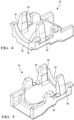
Fig. 4 is a front perspective view of an independent secondary lock of the female coaxial connector assembly ofFig. 2 according to some embodiments; -
Fig. 5 is a rear perspective view of the independent secondary lock ofFig. 4 according to some embodiments; -
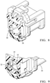
Fig. 6 is a perspective view of the female coaxial connector assembly ofFig. 2 with the independent secondary lock in a pre-staged condition according to some embodiments; -
Fig. 7 is an end view of the female coaxial connector assembly ofFig. 2 with the independent secondary lock in the pre-staged condition according to some embodiments; -
Fig. 8 is perspective lateral cross-section view of the female coaxial connector assembly ofFig. 6 with the independent secondary lock in the pre-staged condition according to some embodiments; -
Fig. 9 is a close-up perspective view of the female coaxial connector assembly ofFig. 6 with the independent secondary lock in a pre-staged condition according to some embodiments; -
Fig. 10 is a perspective lateral cross-section view of the female coaxial connector assembly ofFig. 2 with the independent secondary lock in a staged condition according to some embodiments; -
Fig. 11 is an end cross-section view of the female coaxial connector assembly ofFig. 10 with the independent secondary lock in the staged condition according to some embodiments; -
Fig. 12 is a close-up perspective lateral cross-section view of the female coaxial connector assembly ofFig. 10 with the independent secondary lock in the staged condition according to some embodiments; -
Fig. 13 is an end cross-section view of the female coaxial connector assembly ofFig. 6 with the independent secondary lock in the pre-staged condition according to some embodiments; -
Fig. 14 is an end cross-section view of the female coaxial connector assembly ofFig. 10 with the independent secondary lock in the staged condition according to some embodiments; -
Fig. 15 is a cut-away perspective view of the female coaxial connector assembly ofFig. 6 with the independent secondary lock in the pre-staged condition according to some embodiments; -
Fig. 16 is a cut-away perspective view the female coaxial connector assembly ofFig. 10 with the independent secondary lock in the staged condition according to some embodiments; -
Fig. 17 is a cut-away side view the female coaxial connector assembly ofFig. 10 with the independent secondary lock in the staged condition according to some embodiments; -
Fig. 18 is a perspective longitudinal cross-section view of the female coaxial connector assembly ofFig. 10 with the independent secondary lock in the staged condition according to some embodiments; -
Fig. 19 is a close-up perspective longitudinal cross-section view of the female coaxial connector assembly ofFig. 10 with the independent secondary lock in the staged condition according to some embodiments; -
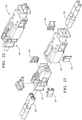
Fig. 20 is a perspective view of a coaxial connector assembly according to some embodiments; -
Fig. 21 is an exploded perspective view of the coaxial connector assembly ofFig. 20 according to some embodiments; -
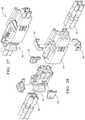
Fig. 22 is a perspective view of a coaxial connector assembly according to some embodiments; -
Fig. 23 is an exploded perspective view of the coaxial connector assembly ofFig. 22 according to some embodiments; -
Fig. 24 is an end cross-section view of the coaxial connector assembly ofFig. 22 according to some embodiments; -
Fig. 25 is a close-up end cross-section view of the coaxial connector assembly ofFig. 22 according to some embodiments; -
Fig. 26 is a side cross-section view of the coaxial connector assembly ofFig. 22 according to some embodiments; -
Fig. 27 is a perspective view of a coaxial connector assembly according to some embodiments; and -
Fig. 28 is an exploded perspective view of the coaxial connector assembly ofFig. 27 according to some embodiments. - Reference will now be made in detail to embodiments, examples of which are illustrated in the accompanying drawings. In the following detailed description, numerous specific details are set forth to provide a thorough understanding of the various described embodiments. However, it will be apparent to one of ordinary skill in the art that the various described embodiments may be practiced without these specific details. In other instances, well-known methods, procedures, components, circuits, and networks have not been described in detail so as not to unnecessarily obscure aspects of the embodiments.
- A coaxial connector assembly that provides a solution to overcome the issues described in the BACKGROUND section by clamping the terminal around its circular geometry while reinforcing the terminal cavity primary locking feature and pushing the terminal toward a forward stop via a wedging action is presented herein. The coaxial connector assembly includes an integrated secondary lock (ISL) feature that has greater overlap with the coaxial terminal and is supported by a wedging action along a lateral axis of the connector. The ISL pushes the coaxial terminal in an axial mating direction to arrest the gap between a flexible primary locking feature in the cavity and a forward stop supported by a ramp wedge arrangement in the cavity. The ISL is integrated with a primary lock reinforcement (PLR) feature. The ISL backs up the terminal cavity primary locks when moved to final staged position. The wedging action of the ISL in the axial mating direction reduces or eliminates the load transferred to the primary locking feature in the cavity by the terminal during contact engagement.
- A nonlimiting example of an embodiment of the
coaxial connector assembly 10 is illustrated inFig 1 . Thiscoaxial connector assembly 10 includes a femalecoaxial connector assembly 12 as shown inFig. 2 and a malecoaxial connector assembly 14 as shown inFig. 3 . Each of the male and female coaxial connector assemblies 12, 14 include aconnector housing 16 defining acavity 18, a cylindricalcoaxial terminal 20 disposed within thecavity 18, a primaryterminal locking feature 22, and an integrated secondary terminal locking (ISL)feature 24. As illustrated inFigs. 4 and 5 , theISL feature 24 has a pair ofarms 26 extending from abase 28. The end of each of thearms 26 defineconcave features 30 that engage thecoaxial terminal 20 as theconcave features 30 are wedged between thecoaxial terminal 20 andinner walls 32 of thecavity 18. Thearms 26 and theconcave features 30 are wedged between thecoaxial terminal 20 and theinner walls 32 of thecavity 18 as theISL feature 24 is moved from apre-staged position 34 shown inFigs. 6-9 to a stagedposition 36 shown inFigs. 10-12 . As used herein, the term "wedged" means that theconcave surfaces 30 are in compressive contact with thecoaxial terminal 20 and thearms 26 are in simultaneous compressive contact with theinner walls 32 of thecavity 18. A radius of the concave features 30 is substantially equal to an outer radius of thecoaxial terminal 20. As illustrated inFig. 8 , theISL feature 24 defines pre-locking features 38 in the form of outwardly oriented tabs that are configured to secure theISL feature 24 to theconnector housing 16 when theISL feature 24 is in thepre-staged position 34. - As can be seen in
Figs. 13 and 14 theinner walls 32 of thecavity 18 form a ramp that is configured to deflect the pair ofarms 26 toward thecoaxial terminal 20 as theISL feature 24 is moved from thepre-staged position 34 to the stagedposition 36. - As shown in
Fig. 15-17 , theISL feature 24 is configured to bias thecoaxial terminal 20 in an axial direction along the mating axis of theconnector assembly 10 toward aforward stop 40 when theISL feature 24 is in the staged position. -
Figs. 18 and 19 illustrates how theISL feature 24 also serves as a retainer for the primaryterminal locking feature 22 when theISL feature 24 is in the stagedposition 36. -
Figs. 20 and 21 illustrate that both the femalecoaxial connector assembly 12 and the malecoaxial connector 14 assembly include theISL feature 24. -
Figs. 22 and 23 illustrate examples of female coaxial connector and malecoaxial connector assemblies coaxial terminals 20.Figs. 27 and 28 illustrate examples of female coaxial connector and malecoaxial connector assemblies - The example presented herein is directed to a coaxial
electrical connector assembly 10. However, alternative embodiments of the connector assembly may be envisioned to connect fiber optic cables, pneumatic tubes, hydraulic tubes, or a hybrid assembly having a combination of any of these types of conductors. - Accordingly, a
coaxial connector assembly 10 is provided. Thecoaxial connector assembly 10 provide the benefits over the prior art coaxial connector assemblies of providing a clamping feature which in cooperation with the along with the wedge, holds the terminal tight, thereby providing maximum retention forces for the coaxial terminal. The wedging and ramp arrangement in theISL feature 24 andcavity 18 push thecoaxial terminal 20 towardsforward stop 40 in thecavity 18 along the axial mating direction, which ensures that the terminal is in proper position and providing maximum interface with mating terminal and arresting the gap between thecoaxial terminal 20 and theforward stop 40. A primary lock retainer (PLR) feature integrated with theISL feature 24 backs up and reinforces primaryterminal locking feature 22 in thecavity 18 for increased terminal retention. The ISL feature 24 also provides the benefit of improving signal integrity of the signal conducted by thecoaxial connector assembly 10 by reducing skew. - While this invention has been described in terms of the preferred embodiments thereof, it is not intended to be so limited, but rather only to the extent set forth in the claims that follow. For example, the above-described embodiments (and/or aspects thereof) may be used in combination with each other. In addition, many modifications may be made to configure a situation or material to the teachings of the invention without departing from its scope. Dimensions, types of materials, orientations of the various components, and the number and positions of the various components described herein are intended to define parameters of certain embodiments and are by no means limiting and are merely prototypical embodiments.
- Many other embodiments and modifications within the spirit and scope of the claims will be apparent to those of skill in the art upon reviewing the above description. The scope of the invention should, therefore, be determined with reference to the following claims, along with the full scope of equivalents to which such claims are entitled.
- As used herein, 'one or more' includes a function being performed by one element, a function being performed by more than one element, e.g., in a distributed fashion, several functions being performed by one element, several functions being performed by several elements, or any combination of the above.
- It will also be understood that, although the terms first, second, etc. are, in some instances, used herein to describe various elements, these elements should not be limited by these terms. These terms are only used to distinguish one element from another. For example, a first contact could be termed a second contact, and, similarly, a second contact could be termed a first contact, without departing from the scope of the various described embodiments. The first contact and the second contact are both contacts, but they are not the same contact.
- The terminology used in the description of the various described embodiments herein is for the purpose of describing embodiments only and is not intended to be limiting. As used in the description of the various described embodiments and the appended claims, the singular forms "a", "an" and "the" are intended to include the plural forms as well, unless the context clearly indicates otherwise. It will also be understood that the term "and/or" as used herein refers to and encompasses all possible combinations of one or more of the associated listed items. It will be further understood that the terms "includes," "including," "comprises," and/or "comprising," when used in this specification, specify the presence of stated features, integers, steps, operations, elements, and/or components, but do not preclude the presence or addition of one or more other features, integers, steps, operations, elements, components, and/or groups thereof.
- As used herein, the term "if' is, optionally, construed to mean "when" or "upon" or "in response to determining" or "in response to detecting," depending on the context. Similarly, the phrase "if it is determined" or "if [a stated condition or event] is detected" is, optionally, construed to mean "upon determining" or "in response to determining" or "upon detecting [the stated condition or event]" or "in response to detecting [the stated condition or event]," depending on the context.
- Additionally, while terms of ordinance or orientation may be used herein these elements should not be limited by these terms. All terms of ordinance or orientation, unless stated otherwise, are used for purposes distinguishing one element from another, and do not denote any order of arrangement, order of operations, direction or orientation unless stated otherwise.
Claims (13)
- A connector assembly (10), comprising:a connector housing (16) defining a cavity (18);a cylindrical terminal (20) disposed within the cavity (18);a primary terminal locking feature (22) configured to retain the cylindrical terminal (20) within the cavity (18); anda secondary terminal locking feature (24) configured to retain the cylindrical terminal (20) within the cavity (18) having a pair of arms (26) defining concave features (30) that engage the cylindrical terminal (20) as the concave features (30) are wedged between the cylindrical terminal (20) and inner walls (32) of the cavity (18).
- The connector assembly (10) according to claim 1, wherein the concave features (30) are wedged between the cylindrical terminal (20) and inner walls (32) of the cavity (18) as the secondary terminal locking feature (24) is moved from a pre-staged position (34) to a staged position (36).
- The connector assembly (10) according to claim 2, wherein the inner walls (32) of the cavity (18) form a ramp configured to deflect the pair of arms (26) in an axial direction toward the cylindrical terminal (20) as the secondary terminal locking feature (24) is moved from the pre-staged position (34) to the staged position (36).
- The connector assembly (10) according to claim 2 or 3, wherein the secondary terminal locking feature (24) is configured to bias the cylindrical terminal (20) toward a forward stop (40) when in the staged position (36).
- The connector assembly (10) according to any one of the preceding claims, wherein a radius of the concave features (30) is substantially equal to an outer radius of the cylindrical terminal (20).
- The connector assembly (10) according to any one of the preceding claims, wherein the secondary terminal locking feature (24) defines pre-locking features (38) configured to secure the secondary terminal locking feature (24) to the connector housing (16) in a pre-staged position (34).
- The connector assembly (10) according to any one of the preceding claims, wherein the connector housing (16) is configured to contain a male connector.
- The connector assembly (10) according to any one of the preceding claims, wherein the connector housing (16) is configured to contain a female connector.
- The connector assembly (10) according to any one of the preceding claims, wherein the connector housing (16) is configured to contain two cylindrical terminals (20).
- The connector assembly (10) according to any one of the preceding claims, wherein the connector housing (16) is configured to contain four cylindrical terminals (20).
- The connector assembly (10) according to any one of the preceding claims, wherein the cylindrical terminal (20) is a coaxial terminal.
- The connector assembly (10) according to any one of the preceding claims, wherein the cylindrical terminal (20) is a coaxial electrical terminal and is attached to a coaxial electrical cable.
- A coaxial electrical connector assembly (10), comprising:a connector housing (16) defining a cavity (18);a cylindrical coaxial terminal (20) attached to a coaxial cable that is disposed within the cavity (18);a primary means (22) for retaining the cylindrical terminal (20) within the cavity (18); anda secondary means (24) for retaining the cylindrical terminal (20) within the cavity (18) that is movable from a pre-staged position (34) to a staged position (36) and having concave features (30) that are wedged between the cylindrical terminal (20) and inner walls (32) of the cavity (18) when in the staged position (36).
Applications Claiming Priority (2)
| Application Number | Priority Date | Filing Date | Title |
|---|---|---|---|
| US202063055955P | 2020-07-24 | 2020-07-24 | |
| US17/365,038 US11545777B2 (en) | 2020-07-24 | 2021-07-01 | Coaxial connector assembly |
Publications (2)
| Publication Number | Publication Date |
|---|---|
| EP3944423A1 true EP3944423A1 (en) | 2022-01-26 |
| EP3944423B1 EP3944423B1 (en) | 2023-12-27 |
Family
ID=77155522
Family Applications (1)
| Application Number | Title | Priority Date | Filing Date |
|---|---|---|---|
| EP21186940.9A Active EP3944423B1 (en) | 2020-07-24 | 2021-07-21 | Coaxial connector assembly |
Country Status (3)
| Country | Link |
|---|---|
| US (1) | US11545777B2 (en) |
| EP (1) | EP3944423B1 (en) |
| CN (1) | CN113972511B (en) |
Cited By (2)
| Publication number | Priority date | Publication date | Assignee | Title |
|---|---|---|---|---|
| CN116581591A (en) * | 2023-07-13 | 2023-08-11 | 深圳市蓝晟电子有限公司 | Connector with a plurality of connectors |
| EP4228100A1 (en) * | 2022-02-10 | 2023-08-16 | Aptiv Technologies Limited | Connector assembly with an unseated terminal detection feature |
Families Citing this family (7)
| Publication number | Priority date | Publication date | Assignee | Title |
|---|---|---|---|---|
| JP7189178B2 (en) * | 2020-05-27 | 2022-12-13 | 矢崎総業株式会社 | connector |
| JP7149542B2 (en) * | 2020-05-27 | 2022-10-07 | 矢崎総業株式会社 | connector |
| WO2023034396A1 (en) | 2021-09-01 | 2023-03-09 | Fci Usa Llc | High speed, ruggedized connector |
| DE102021127030B3 (en) * | 2021-10-19 | 2022-12-22 | Md Elektronik Gmbh | connector |
| US12476422B2 (en) | 2022-09-13 | 2025-11-18 | Aptiv Technologies AG | Electrical connector with comb-type terminal lock |
| US12418131B2 (en) | 2023-05-03 | 2025-09-16 | Aptiv Technologies AG | Primary lock reinforcement for connector locking system with resilient and rigid locking surfaces |
| JP2025086939A (en) * | 2023-11-29 | 2025-06-10 | 矢崎総業株式会社 | connector |
Citations (8)
| Publication number | Priority date | Publication date | Assignee | Title |
|---|---|---|---|---|
| US7347745B1 (en) * | 2007-01-19 | 2008-03-25 | Tyco Electronics Corporation | Three position electrical connector assembly |
| US20090011637A1 (en) * | 2007-07-06 | 2009-01-08 | Hyundai Motor Company | Coaxial cable connector |
| DE202008014541U1 (en) * | 2008-11-03 | 2009-01-29 | Rosenberger Hochfrequenztechnik Gmbh & Co. Kg | Connector with a coding housing |
| KR101482973B1 (en) * | 2013-10-23 | 2015-01-16 | 주식회사 럭스콘테크놀로지 | Connector Union Structure |
| EP3159970A1 (en) * | 2015-10-20 | 2017-04-26 | Hosiden Corporation | Cable assembly, connector, and method for manufacturing cable assembly |
| KR20170070997A (en) * | 2015-12-15 | 2017-06-23 | 한국단자공업 주식회사 | Locking structure of connector and connector |
| JP2019153464A (en) * | 2018-03-02 | 2019-09-12 | 日本圧着端子製造株式会社 | Coaxial connector |
| US20200153144A1 (en) * | 2018-11-12 | 2020-05-14 | Raydiall | Connector housing equipped with an improved cable terminal position assurance (tpa) device |
Family Cites Families (20)
| Publication number | Priority date | Publication date | Assignee | Title |
|---|---|---|---|---|
| JP2003007388A (en) * | 2001-06-18 | 2003-01-10 | Sumitomo Wiring Syst Ltd | Connector |
| US6827609B1 (en) * | 2003-11-12 | 2004-12-07 | Tyco Electronics Corporation | Electrical connector having improved terminal positioning assurance member |
| US7044808B1 (en) * | 2005-06-07 | 2006-05-16 | Tyco Electronics Corporation | Connector assembly with terminal position assurance device |
| JP2006344538A (en) * | 2005-06-10 | 2006-12-21 | Tyco Electronics Amp Kk | Electric connector |
| US7223131B2 (en) * | 2005-09-02 | 2007-05-29 | Tyco Electronics Corporation | Three position electrical connector assembly |
| US7625251B2 (en) * | 2007-09-25 | 2009-12-01 | Tyco Electronics Corporation | Connector with redundant terminal locking |
| US7682205B2 (en) * | 2007-11-15 | 2010-03-23 | Tyco Electronics Corporation | Multi position electrical connector assembly |
| US7682180B2 (en) * | 2008-04-29 | 2010-03-23 | Tyco Electronics Corporation | Electrical connector with integral terminal retention and terminal position assurance |
| US7762854B1 (en) * | 2009-05-19 | 2010-07-27 | F Time Technology Industrial Co., Ltd. | RF connector assembly |
| US10673168B2 (en) * | 2016-01-14 | 2020-06-02 | J.S.T. Corporation | MSL connector series |
| US10622746B2 (en) * | 2016-01-15 | 2020-04-14 | J.S.T. Corporation | Terminal position assurance member and method of operating a terminal position assurance member |
| US9960550B2 (en) * | 2016-07-25 | 2018-05-01 | Delphi Technologies, Inc. | Coaxial connector assembly |
| US9882317B1 (en) * | 2016-09-15 | 2018-01-30 | Te Connectivity Corporation | Connector system with hybrid electrical connectors |
| CN107221811B (en) * | 2017-07-03 | 2023-06-02 | 凡甲电子(苏州)有限公司 | Electric connector and electric connector combination with same |
| JP2019040729A (en) * | 2017-08-24 | 2019-03-14 | モレックス エルエルシー | connector |
| DE102018213920B4 (en) * | 2017-12-12 | 2022-09-29 | Lear Corporation | Method of manufacturing an electrical connector housing assembly having an integral terminal position assurance mechanism and method of manufacturing the connector |
| US10348019B1 (en) * | 2018-04-05 | 2019-07-09 | Delphi Technologies, Llc | Connector assembly with locking feature |
| US10461457B1 (en) * | 2018-07-23 | 2019-10-29 | Yazaki North America, Inc. | Connector housing and terminal position assurance joint clip site |
| US11251560B2 (en) * | 2019-03-11 | 2022-02-15 | TE Connectivity Services Gmbh | Terminal position assurance member with multiple latches |
| US10892577B1 (en) * | 2019-07-10 | 2021-01-12 | Lear Corporation | Electric terminal connector assembly with a terminal lock |
-
2021
- 2021-07-01 US US17/365,038 patent/US11545777B2/en active Active
- 2021-07-21 EP EP21186940.9A patent/EP3944423B1/en active Active
- 2021-07-23 CN CN202110837522.7A patent/CN113972511B/en active Active
Patent Citations (8)
| Publication number | Priority date | Publication date | Assignee | Title |
|---|---|---|---|---|
| US7347745B1 (en) * | 2007-01-19 | 2008-03-25 | Tyco Electronics Corporation | Three position electrical connector assembly |
| US20090011637A1 (en) * | 2007-07-06 | 2009-01-08 | Hyundai Motor Company | Coaxial cable connector |
| DE202008014541U1 (en) * | 2008-11-03 | 2009-01-29 | Rosenberger Hochfrequenztechnik Gmbh & Co. Kg | Connector with a coding housing |
| KR101482973B1 (en) * | 2013-10-23 | 2015-01-16 | 주식회사 럭스콘테크놀로지 | Connector Union Structure |
| EP3159970A1 (en) * | 2015-10-20 | 2017-04-26 | Hosiden Corporation | Cable assembly, connector, and method for manufacturing cable assembly |
| KR20170070997A (en) * | 2015-12-15 | 2017-06-23 | 한국단자공업 주식회사 | Locking structure of connector and connector |
| JP2019153464A (en) * | 2018-03-02 | 2019-09-12 | 日本圧着端子製造株式会社 | Coaxial connector |
| US20200153144A1 (en) * | 2018-11-12 | 2020-05-14 | Raydiall | Connector housing equipped with an improved cable terminal position assurance (tpa) device |
Cited By (3)
| Publication number | Priority date | Publication date | Assignee | Title |
|---|---|---|---|---|
| EP4228100A1 (en) * | 2022-02-10 | 2023-08-16 | Aptiv Technologies Limited | Connector assembly with an unseated terminal detection feature |
| CN116581591A (en) * | 2023-07-13 | 2023-08-11 | 深圳市蓝晟电子有限公司 | Connector with a plurality of connectors |
| CN116581591B (en) * | 2023-07-13 | 2024-02-13 | 深圳市蓝晟电子有限公司 | Connector with a plurality of connectors |
Also Published As
| Publication number | Publication date |
|---|---|
| EP3944423B1 (en) | 2023-12-27 |
| US11545777B2 (en) | 2023-01-03 |
| CN113972511A (en) | 2022-01-25 |
| US20220029336A1 (en) | 2022-01-27 |
| CN113972511B (en) | 2025-08-08 |
Similar Documents
| Publication | Publication Date | Title |
|---|---|---|
| US11545777B2 (en) | Coaxial connector assembly | |
| US9666973B1 (en) | Self-locking connector coupling | |
| EP0895312B1 (en) | An electrical connector having a terminal position assurance device | |
| US7914327B2 (en) | Electrical connector | |
| US11502444B2 (en) | Electrical connector assembly having a male blade stabilizer with integrated primary lock reinforcement | |
| US11515660B2 (en) | Electrical connector assembly with retaining device | |
| US8469751B2 (en) | Electrical connector and harness | |
| EP4228100B1 (en) | Connector assembly with an unseated terminal detection feature | |
| US11942715B2 (en) | Terminal position assurance device and corresponding connector assembly | |
| EP0493632A1 (en) | Electrical connector with externally applied radial lock | |
| EP4297193A1 (en) | Electrical connector assembly with flexible and rigid terminal locking features | |
| EP3503306B1 (en) | Receptacle connector housing with hold-down ribs | |
| US10950967B2 (en) | Electric terminal housing with a terminal lock | |
| US6116953A (en) | Electrical connector having a terminal position assurance device | |
| US20100233904A1 (en) | Electrical connector with releasable locking clip | |
| US11201428B2 (en) | Connector assembly with connector lock and terminal retainer | |
| US12562520B2 (en) | Connector assembly with terminal position assurance and blocking feature | |
| US9923303B2 (en) | Electrical connector with terminal centering system | |
| US11264759B1 (en) | Connector with integrated primary lock reinforcement and terminal position assurance | |
| US11450985B2 (en) | Connector with integrated seal retainer and secondary terminal lock | |
| US10476207B2 (en) | Electrical distribution assembly | |
| EP4125163B1 (en) | Self-ejecting electrical connection system | |
| US20250105560A1 (en) | Connector | |
| CN116581580A (en) | Connector assembly with dislocating terminal detection function |
Legal Events
| Date | Code | Title | Description |
|---|---|---|---|
| PUAI | Public reference made under article 153(3) epc to a published international application that has entered the european phase |
Free format text: ORIGINAL CODE: 0009012 |
|
| STAA | Information on the status of an ep patent application or granted ep patent |
Free format text: STATUS: THE APPLICATION HAS BEEN PUBLISHED |
|
| AK | Designated contracting states |
Kind code of ref document: A1 Designated state(s): AL AT BE BG CH CY CZ DE DK EE ES FI FR GB GR HR HU IE IS IT LI LT LU LV MC MK MT NL NO PL PT RO RS SE SI SK SM TR |
|
| STAA | Information on the status of an ep patent application or granted ep patent |
Free format text: STATUS: REQUEST FOR EXAMINATION WAS MADE |
|
| 17P | Request for examination filed |
Effective date: 20220712 |
|
| RBV | Designated contracting states (corrected) |
Designated state(s): AL AT BE BG CH CY CZ DE DK EE ES FI FR GB GR HR HU IE IS IT LI LT LU LV MC MK MT NL NO PL PT RO RS SE SI SK SM TR |
|
| RAP3 | Party data changed (applicant data changed or rights of an application transferred) |
Owner name: APTIV TECHNOLOGIES LIMITED |
|
| GRAP | Despatch of communication of intention to grant a patent |
Free format text: ORIGINAL CODE: EPIDOSNIGR1 |
|
| STAA | Information on the status of an ep patent application or granted ep patent |
Free format text: STATUS: GRANT OF PATENT IS INTENDED |
|
| RIC1 | Information provided on ipc code assigned before grant |
Ipc: H01R 13/436 20060101ALN20231004BHEP Ipc: H01R 13/422 20060101ALI20231004BHEP Ipc: H01R 24/40 20110101ALI20231004BHEP Ipc: H01R 13/426 20060101AFI20231004BHEP |
|
| INTG | Intention to grant announced |
Effective date: 20231019 |
|
| GRAS | Grant fee paid |
Free format text: ORIGINAL CODE: EPIDOSNIGR3 |
|
| GRAA | (expected) grant |
Free format text: ORIGINAL CODE: 0009210 |
|
| STAA | Information on the status of an ep patent application or granted ep patent |
Free format text: STATUS: THE PATENT HAS BEEN GRANTED |
|
| P01 | Opt-out of the competence of the unified patent court (upc) registered |
Effective date: 20231107 |
|
| AK | Designated contracting states |
Kind code of ref document: B1 Designated state(s): AL AT BE BG CH CY CZ DE DK EE ES FI FR GB GR HR HU IE IS IT LI LT LU LV MC MK MT NL NO PL PT RO RS SE SI SK SM TR |
|
| REG | Reference to a national code |
Ref country code: GB Ref legal event code: FG4D |
|
| REG | Reference to a national code |
Ref country code: CH Ref legal event code: EP |
|
| REG | Reference to a national code |
Ref country code: DE Ref legal event code: R096 Ref document number: 602021008036 Country of ref document: DE |
|
| REG | Reference to a national code |
Ref country code: IE Ref legal event code: FG4D |
|
| PG25 | Lapsed in a contracting state [announced via postgrant information from national office to epo] |
Ref country code: GR Free format text: LAPSE BECAUSE OF FAILURE TO SUBMIT A TRANSLATION OF THE DESCRIPTION OR TO PAY THE FEE WITHIN THE PRESCRIBED TIME-LIMIT Effective date: 20240328 |
|
| REG | Reference to a national code |
Ref country code: LT Ref legal event code: MG9D |
|
| PG25 | Lapsed in a contracting state [announced via postgrant information from national office to epo] |
Ref country code: LT Free format text: LAPSE BECAUSE OF FAILURE TO SUBMIT A TRANSLATION OF THE DESCRIPTION OR TO PAY THE FEE WITHIN THE PRESCRIBED TIME-LIMIT Effective date: 20231227 |
|
| PG25 | Lapsed in a contracting state [announced via postgrant information from national office to epo] |
Ref country code: ES Free format text: LAPSE BECAUSE OF FAILURE TO SUBMIT A TRANSLATION OF THE DESCRIPTION OR TO PAY THE FEE WITHIN THE PRESCRIBED TIME-LIMIT Effective date: 20231227 |
|
| PG25 | Lapsed in a contracting state [announced via postgrant information from national office to epo] |
Ref country code: LT Free format text: LAPSE BECAUSE OF FAILURE TO SUBMIT A TRANSLATION OF THE DESCRIPTION OR TO PAY THE FEE WITHIN THE PRESCRIBED TIME-LIMIT Effective date: 20231227 Ref country code: GR Free format text: LAPSE BECAUSE OF FAILURE TO SUBMIT A TRANSLATION OF THE DESCRIPTION OR TO PAY THE FEE WITHIN THE PRESCRIBED TIME-LIMIT Effective date: 20240328 Ref country code: FI Free format text: LAPSE BECAUSE OF FAILURE TO SUBMIT A TRANSLATION OF THE DESCRIPTION OR TO PAY THE FEE WITHIN THE PRESCRIBED TIME-LIMIT Effective date: 20231227 Ref country code: ES Free format text: LAPSE BECAUSE OF FAILURE TO SUBMIT A TRANSLATION OF THE DESCRIPTION OR TO PAY THE FEE WITHIN THE PRESCRIBED TIME-LIMIT Effective date: 20231227 Ref country code: BG Free format text: LAPSE BECAUSE OF FAILURE TO SUBMIT A TRANSLATION OF THE DESCRIPTION OR TO PAY THE FEE WITHIN THE PRESCRIBED TIME-LIMIT Effective date: 20240327 |
|
| REG | Reference to a national code |
Ref country code: NL Ref legal event code: MP Effective date: 20231227 |
|
| REG | Reference to a national code |
Ref country code: AT Ref legal event code: MK05 Ref document number: 1645419 Country of ref document: AT Kind code of ref document: T Effective date: 20231227 |
|
| PG25 | Lapsed in a contracting state [announced via postgrant information from national office to epo] |
Ref country code: NL Free format text: LAPSE BECAUSE OF FAILURE TO SUBMIT A TRANSLATION OF THE DESCRIPTION OR TO PAY THE FEE WITHIN THE PRESCRIBED TIME-LIMIT Effective date: 20231227 |
|
| PG25 | Lapsed in a contracting state [announced via postgrant information from national office to epo] |
Ref country code: SE Free format text: LAPSE BECAUSE OF FAILURE TO SUBMIT A TRANSLATION OF THE DESCRIPTION OR TO PAY THE FEE WITHIN THE PRESCRIBED TIME-LIMIT Effective date: 20231227 Ref country code: RS Free format text: LAPSE BECAUSE OF FAILURE TO SUBMIT A TRANSLATION OF THE DESCRIPTION OR TO PAY THE FEE WITHIN THE PRESCRIBED TIME-LIMIT Effective date: 20231227 Ref country code: NO Free format text: LAPSE BECAUSE OF FAILURE TO SUBMIT A TRANSLATION OF THE DESCRIPTION OR TO PAY THE FEE WITHIN THE PRESCRIBED TIME-LIMIT Effective date: 20240327 Ref country code: NL Free format text: LAPSE BECAUSE OF FAILURE TO SUBMIT A TRANSLATION OF THE DESCRIPTION OR TO PAY THE FEE WITHIN THE PRESCRIBED TIME-LIMIT Effective date: 20231227 Ref country code: LV Free format text: LAPSE BECAUSE OF FAILURE TO SUBMIT A TRANSLATION OF THE DESCRIPTION OR TO PAY THE FEE WITHIN THE PRESCRIBED TIME-LIMIT Effective date: 20231227 Ref country code: HR Free format text: LAPSE BECAUSE OF FAILURE TO SUBMIT A TRANSLATION OF THE DESCRIPTION OR TO PAY THE FEE WITHIN THE PRESCRIBED TIME-LIMIT Effective date: 20231227 |
|
| PG25 | Lapsed in a contracting state [announced via postgrant information from national office to epo] |
Ref country code: IS Free format text: LAPSE BECAUSE OF FAILURE TO SUBMIT A TRANSLATION OF THE DESCRIPTION OR TO PAY THE FEE WITHIN THE PRESCRIBED TIME-LIMIT Effective date: 20240427 |
|
| PG25 | Lapsed in a contracting state [announced via postgrant information from national office to epo] |
Ref country code: CZ Free format text: LAPSE BECAUSE OF FAILURE TO SUBMIT A TRANSLATION OF THE DESCRIPTION OR TO PAY THE FEE WITHIN THE PRESCRIBED TIME-LIMIT Effective date: 20231227 Ref country code: AT Free format text: LAPSE BECAUSE OF FAILURE TO SUBMIT A TRANSLATION OF THE DESCRIPTION OR TO PAY THE FEE WITHIN THE PRESCRIBED TIME-LIMIT Effective date: 20231227 |
|
| PG25 | Lapsed in a contracting state [announced via postgrant information from national office to epo] |
Ref country code: SK Free format text: LAPSE BECAUSE OF FAILURE TO SUBMIT A TRANSLATION OF THE DESCRIPTION OR TO PAY THE FEE WITHIN THE PRESCRIBED TIME-LIMIT Effective date: 20231227 |
|
| PG25 | Lapsed in a contracting state [announced via postgrant information from national office to epo] |
Ref country code: SM Free format text: LAPSE BECAUSE OF FAILURE TO SUBMIT A TRANSLATION OF THE DESCRIPTION OR TO PAY THE FEE WITHIN THE PRESCRIBED TIME-LIMIT Effective date: 20231227 Ref country code: SK Free format text: LAPSE BECAUSE OF FAILURE TO SUBMIT A TRANSLATION OF THE DESCRIPTION OR TO PAY THE FEE WITHIN THE PRESCRIBED TIME-LIMIT Effective date: 20231227 Ref country code: RO Free format text: LAPSE BECAUSE OF FAILURE TO SUBMIT A TRANSLATION OF THE DESCRIPTION OR TO PAY THE FEE WITHIN THE PRESCRIBED TIME-LIMIT Effective date: 20231227 Ref country code: IT Free format text: LAPSE BECAUSE OF FAILURE TO SUBMIT A TRANSLATION OF THE DESCRIPTION OR TO PAY THE FEE WITHIN THE PRESCRIBED TIME-LIMIT Effective date: 20231227 Ref country code: IS Free format text: LAPSE BECAUSE OF FAILURE TO SUBMIT A TRANSLATION OF THE DESCRIPTION OR TO PAY THE FEE WITHIN THE PRESCRIBED TIME-LIMIT Effective date: 20240427 Ref country code: EE Free format text: LAPSE BECAUSE OF FAILURE TO SUBMIT A TRANSLATION OF THE DESCRIPTION OR TO PAY THE FEE WITHIN THE PRESCRIBED TIME-LIMIT Effective date: 20231227 Ref country code: CZ Free format text: LAPSE BECAUSE OF FAILURE TO SUBMIT A TRANSLATION OF THE DESCRIPTION OR TO PAY THE FEE WITHIN THE PRESCRIBED TIME-LIMIT Effective date: 20231227 Ref country code: AT Free format text: LAPSE BECAUSE OF FAILURE TO SUBMIT A TRANSLATION OF THE DESCRIPTION OR TO PAY THE FEE WITHIN THE PRESCRIBED TIME-LIMIT Effective date: 20231227 |
|
| PG25 | Lapsed in a contracting state [announced via postgrant information from national office to epo] |
Ref country code: PL Free format text: LAPSE BECAUSE OF FAILURE TO SUBMIT A TRANSLATION OF THE DESCRIPTION OR TO PAY THE FEE WITHIN THE PRESCRIBED TIME-LIMIT Effective date: 20231227 Ref country code: PT Free format text: LAPSE BECAUSE OF FAILURE TO SUBMIT A TRANSLATION OF THE DESCRIPTION OR TO PAY THE FEE WITHIN THE PRESCRIBED TIME-LIMIT Effective date: 20240429 |
|
| PG25 | Lapsed in a contracting state [announced via postgrant information from national office to epo] |
Ref country code: PT Free format text: LAPSE BECAUSE OF FAILURE TO SUBMIT A TRANSLATION OF THE DESCRIPTION OR TO PAY THE FEE WITHIN THE PRESCRIBED TIME-LIMIT Effective date: 20240429 Ref country code: PL Free format text: LAPSE BECAUSE OF FAILURE TO SUBMIT A TRANSLATION OF THE DESCRIPTION OR TO PAY THE FEE WITHIN THE PRESCRIBED TIME-LIMIT Effective date: 20231227 |
|
| REG | Reference to a national code |
Ref country code: DE Ref legal event code: R097 Ref document number: 602021008036 Country of ref document: DE |
|
| PG25 | Lapsed in a contracting state [announced via postgrant information from national office to epo] |
Ref country code: DK Free format text: LAPSE BECAUSE OF FAILURE TO SUBMIT A TRANSLATION OF THE DESCRIPTION OR TO PAY THE FEE WITHIN THE PRESCRIBED TIME-LIMIT Effective date: 20231227 |
|
| PG25 | Lapsed in a contracting state [announced via postgrant information from national office to epo] |
Ref country code: DK Free format text: LAPSE BECAUSE OF FAILURE TO SUBMIT A TRANSLATION OF THE DESCRIPTION OR TO PAY THE FEE WITHIN THE PRESCRIBED TIME-LIMIT Effective date: 20231227 |
|
| PLBE | No opposition filed within time limit |
Free format text: ORIGINAL CODE: 0009261 |
|
| STAA | Information on the status of an ep patent application or granted ep patent |
Free format text: STATUS: NO OPPOSITION FILED WITHIN TIME LIMIT |
|
| 26N | No opposition filed |
Effective date: 20240930 |
|
| PG25 | Lapsed in a contracting state [announced via postgrant information from national office to epo] |
Ref country code: MC Free format text: LAPSE BECAUSE OF FAILURE TO SUBMIT A TRANSLATION OF THE DESCRIPTION OR TO PAY THE FEE WITHIN THE PRESCRIBED TIME-LIMIT Effective date: 20231227 |
|
| REG | Reference to a national code |
Ref country code: CH Ref legal event code: PL |
|
| PG25 | Lapsed in a contracting state [announced via postgrant information from national office to epo] |
Ref country code: LU Free format text: LAPSE BECAUSE OF NON-PAYMENT OF DUE FEES Effective date: 20240721 |
|
| PG25 | Lapsed in a contracting state [announced via postgrant information from national office to epo] |
Ref country code: LU Free format text: LAPSE BECAUSE OF NON-PAYMENT OF DUE FEES Effective date: 20240721 |
|
| PG25 | Lapsed in a contracting state [announced via postgrant information from national office to epo] |
Ref country code: SI Free format text: LAPSE BECAUSE OF FAILURE TO SUBMIT A TRANSLATION OF THE DESCRIPTION OR TO PAY THE FEE WITHIN THE PRESCRIBED TIME-LIMIT Effective date: 20231227 Ref country code: BE Free format text: LAPSE BECAUSE OF NON-PAYMENT OF DUE FEES Effective date: 20240731 Ref country code: CH Free format text: LAPSE BECAUSE OF NON-PAYMENT OF DUE FEES Effective date: 20240731 |
|
| REG | Reference to a national code |
Ref country code: DE Ref legal event code: R081 Ref document number: 602021008036 Country of ref document: DE Owner name: APTIV TECHNOLOGIES AG, CH Free format text: FORMER OWNER: APTIV TECHNOLOGIES LIMITED, ST. MICHAEL, BB |
|
| REG | Reference to a national code |
Ref country code: BE Ref legal event code: MM Effective date: 20240731 |
|
| PG25 | Lapsed in a contracting state [announced via postgrant information from national office to epo] |
Ref country code: IE Free format text: LAPSE BECAUSE OF NON-PAYMENT OF DUE FEES Effective date: 20240721 |
|
| PGFP | Annual fee paid to national office [announced via postgrant information from national office to epo] |
Ref country code: DE Payment date: 20250618 Year of fee payment: 5 |
|
| PGFP | Annual fee paid to national office [announced via postgrant information from national office to epo] |
Ref country code: GB Payment date: 20250703 Year of fee payment: 5 |
|
| PGFP | Annual fee paid to national office [announced via postgrant information from national office to epo] |
Ref country code: FR Payment date: 20250703 Year of fee payment: 5 |
|
| PG25 | Lapsed in a contracting state [announced via postgrant information from national office to epo] |
Ref country code: CY Free format text: LAPSE BECAUSE OF FAILURE TO SUBMIT A TRANSLATION OF THE DESCRIPTION OR TO PAY THE FEE WITHIN THE PRESCRIBED TIME-LIMIT; INVALID AB INITIO Effective date: 20210721 |
|
| PG25 | Lapsed in a contracting state [announced via postgrant information from national office to epo] |
Ref country code: HU Free format text: LAPSE BECAUSE OF FAILURE TO SUBMIT A TRANSLATION OF THE DESCRIPTION OR TO PAY THE FEE WITHIN THE PRESCRIBED TIME-LIMIT; INVALID AB INITIO Effective date: 20210721 |