EP3944421A2 - Electrical ferrule, electrical connecting device and electrical connector - Google Patents
Electrical ferrule, electrical connecting device and electrical connector Download PDFInfo
- Publication number
- EP3944421A2 EP3944421A2 EP21187479.7A EP21187479A EP3944421A2 EP 3944421 A2 EP3944421 A2 EP 3944421A2 EP 21187479 A EP21187479 A EP 21187479A EP 3944421 A2 EP3944421 A2 EP 3944421A2
- Authority
- EP
- European Patent Office
- Prior art keywords
- ferrule
- electrical
- flank
- circumferential
- cable
- Prior art date
- Legal status (The legal status is an assumption and is not a legal conclusion. Google has not performed a legal analysis and makes no representation as to the accuracy of the status listed.)
- Pending
Links
- 238000002788 crimping Methods 0.000 claims description 28
- 239000011324 bead Substances 0.000 claims description 18
- 239000000463 material Substances 0.000 claims description 16
- 239000004020 conductor Substances 0.000 description 9
- 238000000034 method Methods 0.000 description 7
- 230000005540 biological transmission Effects 0.000 description 5
- 230000013011 mating Effects 0.000 description 5
- 239000002184 metal Substances 0.000 description 5
- 239000007795 chemical reaction product Substances 0.000 description 4
- 238000005516 engineering process Methods 0.000 description 4
- 238000013461 design Methods 0.000 description 3
- 230000005611 electricity Effects 0.000 description 3
- 239000012530 fluid Substances 0.000 description 3
- 238000004891 communication Methods 0.000 description 2
- 230000000295 complement effect Effects 0.000 description 2
- 238000010586 diagram Methods 0.000 description 2
- 238000009413 insulation Methods 0.000 description 2
- 229910001092 metal group alloy Inorganic materials 0.000 description 2
- 230000001681 protective effect Effects 0.000 description 2
- 230000001960 triggered effect Effects 0.000 description 2
- 229910000831 Steel Inorganic materials 0.000 description 1
- 230000006978 adaptation Effects 0.000 description 1
- 239000011248 coating agent Substances 0.000 description 1
- 238000000576 coating method Methods 0.000 description 1
- 150000001875 compounds Chemical class 0.000 description 1
- 230000006835 compression Effects 0.000 description 1
- 238000007906 compression Methods 0.000 description 1
- 238000010276 construction Methods 0.000 description 1
- 230000008878 coupling Effects 0.000 description 1
- 238000010168 coupling process Methods 0.000 description 1
- 238000005859 coupling reaction Methods 0.000 description 1
- 230000001419 dependent effect Effects 0.000 description 1
- 230000008021 deposition Effects 0.000 description 1
- 238000011161 development Methods 0.000 description 1
- 230000018109 developmental process Effects 0.000 description 1
- 230000000694 effects Effects 0.000 description 1
- 238000004870 electrical engineering Methods 0.000 description 1
- 238000009434 installation Methods 0.000 description 1
- 238000002955 isolation Methods 0.000 description 1
- 230000005923 long-lasting effect Effects 0.000 description 1
- 238000004519 manufacturing process Methods 0.000 description 1
- 239000002905 metal composite material Substances 0.000 description 1
- 230000003287 optical effect Effects 0.000 description 1
- 229920000642 polymer Polymers 0.000 description 1
- 239000010935 stainless steel Substances 0.000 description 1
- 229910001220 stainless steel Inorganic materials 0.000 description 1
- 230000003068 static effect Effects 0.000 description 1
- 239000010959 steel Substances 0.000 description 1
- 238000012546 transfer Methods 0.000 description 1
Images





Classifications
-
- H—ELECTRICITY
- H01—ELECTRIC ELEMENTS
- H01R—ELECTRICALLY-CONDUCTIVE CONNECTIONS; STRUCTURAL ASSOCIATIONS OF A PLURALITY OF MUTUALLY-INSULATED ELECTRICAL CONNECTING ELEMENTS; COUPLING DEVICES; CURRENT COLLECTORS
- H01R13/00—Details of coupling devices of the kinds covered by groups H01R12/70 or H01R24/00 - H01R33/00
- H01R13/648—Protective earth or shield arrangements on coupling devices, e.g. anti-static shielding
- H01R13/658—High frequency shielding arrangements, e.g. against EMI [Electro-Magnetic Interference] or EMP [Electro-Magnetic Pulse]
- H01R13/6591—Specific features or arrangements of connection of shield to conductive members
- H01R13/6592—Specific features or arrangements of connection of shield to conductive members the conductive member being a shielded cable
- H01R13/6593—Specific features or arrangements of connection of shield to conductive members the conductive member being a shielded cable the shield being composed of different pieces
-
- H—ELECTRICITY
- H01—ELECTRIC ELEMENTS
- H01R—ELECTRICALLY-CONDUCTIVE CONNECTIONS; STRUCTURAL ASSOCIATIONS OF A PLURALITY OF MUTUALLY-INSULATED ELECTRICAL CONNECTING ELEMENTS; COUPLING DEVICES; CURRENT COLLECTORS
- H01R24/00—Two-part coupling devices, or either of their cooperating parts, characterised by their overall structure
- H01R24/38—Two-part coupling devices, or either of their cooperating parts, characterised by their overall structure having concentrically or coaxially arranged contacts
-
- H—ELECTRICITY
- H01—ELECTRIC ELEMENTS
- H01R—ELECTRICALLY-CONDUCTIVE CONNECTIONS; STRUCTURAL ASSOCIATIONS OF A PLURALITY OF MUTUALLY-INSULATED ELECTRICAL CONNECTING ELEMENTS; COUPLING DEVICES; CURRENT COLLECTORS
- H01R24/00—Two-part coupling devices, or either of their cooperating parts, characterised by their overall structure
- H01R24/38—Two-part coupling devices, or either of their cooperating parts, characterised by their overall structure having concentrically or coaxially arranged contacts
- H01R24/40—Two-part coupling devices, or either of their cooperating parts, characterised by their overall structure having concentrically or coaxially arranged contacts specially adapted for high frequency
- H01R24/54—Intermediate parts, e.g. adapters, splitters or elbows
-
- H—ELECTRICITY
- H01—ELECTRIC ELEMENTS
- H01R—ELECTRICALLY-CONDUCTIVE CONNECTIONS; STRUCTURAL ASSOCIATIONS OF A PLURALITY OF MUTUALLY-INSULATED ELECTRICAL CONNECTING ELEMENTS; COUPLING DEVICES; CURRENT COLLECTORS
- H01R13/00—Details of coupling devices of the kinds covered by groups H01R12/70 or H01R24/00 - H01R33/00
- H01R13/40—Securing contact members in or to a base or case; Insulating of contact members
- H01R13/42—Securing in a demountable manner
- H01R13/436—Securing a plurality of contact members by one locking piece or operation
-
- H—ELECTRICITY
- H01—ELECTRIC ELEMENTS
- H01R—ELECTRICALLY-CONDUCTIVE CONNECTIONS; STRUCTURAL ASSOCIATIONS OF A PLURALITY OF MUTUALLY-INSULATED ELECTRICAL CONNECTING ELEMENTS; COUPLING DEVICES; CURRENT COLLECTORS
- H01R13/00—Details of coupling devices of the kinds covered by groups H01R12/70 or H01R24/00 - H01R33/00
- H01R13/58—Means for relieving strain on wire connection, e.g. cord grip, for avoiding loosening of connections between wires and terminals within a coupling device terminating a cable
- H01R13/59—Threaded ferrule or bolt operating in a direction parallel to the cable or wire
-
- H—ELECTRICITY
- H01—ELECTRIC ELEMENTS
- H01R—ELECTRICALLY-CONDUCTIVE CONNECTIONS; STRUCTURAL ASSOCIATIONS OF A PLURALITY OF MUTUALLY-INSULATED ELECTRICAL CONNECTING ELEMENTS; COUPLING DEVICES; CURRENT COLLECTORS
- H01R13/00—Details of coupling devices of the kinds covered by groups H01R12/70 or H01R24/00 - H01R33/00
- H01R13/62—Means for facilitating engagement or disengagement of coupling parts or for holding them in engagement
- H01R13/639—Additional means for holding or locking coupling parts together, after engagement, e.g. separate keylock, retainer strap
-
- H—ELECTRICITY
- H01—ELECTRIC ELEMENTS
- H01R—ELECTRICALLY-CONDUCTIVE CONNECTIONS; STRUCTURAL ASSOCIATIONS OF A PLURALITY OF MUTUALLY-INSULATED ELECTRICAL CONNECTING ELEMENTS; COUPLING DEVICES; CURRENT COLLECTORS
- H01R13/00—Details of coupling devices of the kinds covered by groups H01R12/70 or H01R24/00 - H01R33/00
- H01R13/646—Details of coupling devices of the kinds covered by groups H01R12/70 or H01R24/00 - H01R33/00 specially adapted for high-frequency, e.g. structures providing an impedance match or phase match
- H01R13/6473—Impedance matching
-
- H—ELECTRICITY
- H01—ELECTRIC ELEMENTS
- H01R—ELECTRICALLY-CONDUCTIVE CONNECTIONS; STRUCTURAL ASSOCIATIONS OF A PLURALITY OF MUTUALLY-INSULATED ELECTRICAL CONNECTING ELEMENTS; COUPLING DEVICES; CURRENT COLLECTORS
- H01R13/00—Details of coupling devices of the kinds covered by groups H01R12/70 or H01R24/00 - H01R33/00
- H01R13/648—Protective earth or shield arrangements on coupling devices, e.g. anti-static shielding
- H01R13/658—High frequency shielding arrangements, e.g. against EMI [Electro-Magnetic Interference] or EMP [Electro-Magnetic Pulse]
- H01R13/6581—Shield structure
-
- H—ELECTRICITY
- H01—ELECTRIC ELEMENTS
- H01R—ELECTRICALLY-CONDUCTIVE CONNECTIONS; STRUCTURAL ASSOCIATIONS OF A PLURALITY OF MUTUALLY-INSULATED ELECTRICAL CONNECTING ELEMENTS; COUPLING DEVICES; CURRENT COLLECTORS
- H01R13/00—Details of coupling devices of the kinds covered by groups H01R12/70 or H01R24/00 - H01R33/00
- H01R13/648—Protective earth or shield arrangements on coupling devices, e.g. anti-static shielding
- H01R13/658—High frequency shielding arrangements, e.g. against EMI [Electro-Magnetic Interference] or EMP [Electro-Magnetic Pulse]
- H01R13/6591—Specific features or arrangements of connection of shield to conductive members
- H01R13/65912—Specific features or arrangements of connection of shield to conductive members for shielded multiconductor cable
- H01R13/65917—Connection to shield by means of resilient members
-
- H—ELECTRICITY
- H01—ELECTRIC ELEMENTS
- H01R—ELECTRICALLY-CONDUCTIVE CONNECTIONS; STRUCTURAL ASSOCIATIONS OF A PLURALITY OF MUTUALLY-INSULATED ELECTRICAL CONNECTING ELEMENTS; COUPLING DEVICES; CURRENT COLLECTORS
- H01R4/00—Electrically-conductive connections between two or more conductive members in direct contact, i.e. touching one another; Means for effecting or maintaining such contact; Electrically-conductive connections having two or more spaced connecting locations for conductors and using contact members penetrating insulation
- H01R4/10—Electrically-conductive connections between two or more conductive members in direct contact, i.e. touching one another; Means for effecting or maintaining such contact; Electrically-conductive connections having two or more spaced connecting locations for conductors and using contact members penetrating insulation effected solely by twisting, wrapping, bending, crimping, or other permanent deformation
- H01R4/18—Electrically-conductive connections between two or more conductive members in direct contact, i.e. touching one another; Means for effecting or maintaining such contact; Electrically-conductive connections having two or more spaced connecting locations for conductors and using contact members penetrating insulation effected solely by twisting, wrapping, bending, crimping, or other permanent deformation by crimping
- H01R4/183—Electrically-conductive connections between two or more conductive members in direct contact, i.e. touching one another; Means for effecting or maintaining such contact; Electrically-conductive connections having two or more spaced connecting locations for conductors and using contact members penetrating insulation effected solely by twisting, wrapping, bending, crimping, or other permanent deformation by crimping for cylindrical elongated bodies, e.g. cables having circular cross-section
- H01R4/184—Electrically-conductive connections between two or more conductive members in direct contact, i.e. touching one another; Means for effecting or maintaining such contact; Electrically-conductive connections having two or more spaced connecting locations for conductors and using contact members penetrating insulation effected solely by twisting, wrapping, bending, crimping, or other permanent deformation by crimping for cylindrical elongated bodies, e.g. cables having circular cross-section comprising a U-shaped wire-receiving portion
- H01R4/185—Electrically-conductive connections between two or more conductive members in direct contact, i.e. touching one another; Means for effecting or maintaining such contact; Electrically-conductive connections having two or more spaced connecting locations for conductors and using contact members penetrating insulation effected solely by twisting, wrapping, bending, crimping, or other permanent deformation by crimping for cylindrical elongated bodies, e.g. cables having circular cross-section comprising a U-shaped wire-receiving portion combined with a U-shaped insulation-receiving portion
-
- H—ELECTRICITY
- H01—ELECTRIC ELEMENTS
- H01R—ELECTRICALLY-CONDUCTIVE CONNECTIONS; STRUCTURAL ASSOCIATIONS OF A PLURALITY OF MUTUALLY-INSULATED ELECTRICAL CONNECTING ELEMENTS; COUPLING DEVICES; CURRENT COLLECTORS
- H01R9/00—Structural associations of a plurality of mutually-insulated electrical connecting elements, e.g. terminal strips or terminal blocks; Terminals or binding posts mounted upon a base or in a case; Bases therefor
- H01R9/03—Connectors arranged to contact a plurality of the conductors of a multiconductor cable, e.g. tapping connections
- H01R9/05—Connectors arranged to contact a plurality of the conductors of a multiconductor cable, e.g. tapping connections for coaxial cables
- H01R9/0518—Connection to outer conductor by crimping or by crimping ferrule
-
- H—ELECTRICITY
- H01—ELECTRIC ELEMENTS
- H01R—ELECTRICALLY-CONDUCTIVE CONNECTIONS; STRUCTURAL ASSOCIATIONS OF A PLURALITY OF MUTUALLY-INSULATED ELECTRICAL CONNECTING ELEMENTS; COUPLING DEVICES; CURRENT COLLECTORS
- H01R9/00—Structural associations of a plurality of mutually-insulated electrical connecting elements, e.g. terminal strips or terminal blocks; Terminals or binding posts mounted upon a base or in a case; Bases therefor
- H01R9/03—Connectors arranged to contact a plurality of the conductors of a multiconductor cable, e.g. tapping connections
- H01R9/05—Connectors arranged to contact a plurality of the conductors of a multiconductor cable, e.g. tapping connections for coaxial cables
- H01R9/0524—Connection to outer conductor by action of a clamping member, e.g. screw fastening means
-
- H—ELECTRICITY
- H01—ELECTRIC ELEMENTS
- H01R—ELECTRICALLY-CONDUCTIVE CONNECTIONS; STRUCTURAL ASSOCIATIONS OF A PLURALITY OF MUTUALLY-INSULATED ELECTRICAL CONNECTING ELEMENTS; COUPLING DEVICES; CURRENT COLLECTORS
- H01R2103/00—Two poles
-
- H—ELECTRICITY
- H01—ELECTRIC ELEMENTS
- H01R—ELECTRICALLY-CONDUCTIVE CONNECTIONS; STRUCTURAL ASSOCIATIONS OF A PLURALITY OF MUTUALLY-INSULATED ELECTRICAL CONNECTING ELEMENTS; COUPLING DEVICES; CURRENT COLLECTORS
- H01R2201/00—Connectors or connections adapted for particular applications
- H01R2201/26—Connectors or connections adapted for particular applications for vehicles
Definitions
- the invention relates to an electrical ferrule, in particular an HF ferrule, for an electrical connecting device, in particular an HF data connecting device, preferably for the automotive sector.
- the invention also relates to an electrical contact means for an electrical contact device or an electrical connector, to an electrical connecting device for an electrical connector, to an electrical connector and to an electrical entity, preferably in each case for the automotive sector.
- Such a connector, and possibly its associated housing (for example in the case of a connector means or a connector device) or higher-level housing (for example in the case of a connector device), can be installed on an electrical line, a cable, a cable harness, etc. - referred to below as a preassembled (electrical) cable (also: electrical entity) - , or on/in an electrical device or means, such as for example on/in a housing, on a leadframe, on a circuit board etc., of a (power) electrical, electrooptical or electronic component part or a corresponding assembly, etc. (electrical entity).
- a preassembled (electrical) cable also: electrical entity
- an electrical device or means such as for example on/in a housing, on a leadframe, on a circuit board etc., of a (power) electrical, electrooptical or electronic component part or a corresponding assembly, etc. (electrical entity).
- a connector with/without a housing
- this is also called a flying-lead (plug-in) connector or a plug, a socket or a coupling
- a connector device such as for example a (built-in/attached) connector, a (built-in/attached) plug or a (built-in/attached) socket.
- a connector on such a device is often referred to as a (plug) holder, box header connector, pin strip or header.
- an electrical connecting device for a connector for example comprising or at least having an actual contact means (terminal; usually formed as a single piece of material or integrally, for example a contact element, etc.) or a contact device (terminal; usually formed as many parts, two parts, a single part, a single piece of material or integrally, for example a one- or multi-part (crimp) contact device), must be held securely therein.
- a connecting device may be provided as a connector (cf. above), that is to say without a housing, for example in a flying-lead manner.
- the ferrule should be designed for different cable diameters and/or be able to adapt itself to changing diameters of a cable during a preassembly process of the cable.
- the ferrule, the connecting device and the connector can be produced at low cost in comparison with its later use and is of a simple construction and/or is easy to handle.
- the object of the invention is achieved by means of an electrical ferrule, in particular an HF ferrule, for an electrical connecting device, by means of an electrical contact means for an electrical contact device or an electrical connector, by means of an electrical connecting device for an electrical connector, by means of an electrical connector and by means of an electrical entity, preferably in each case for the automotive sector.
- the ferrule according to the invention merely comprises two flanks which extend in axial direction of the ferrule, lie opposite one another in radial direction of the ferrule and are connected to one another in the circumferential direction of the ferrule by way of a circumferential centre portion.
- at least one self-locking of the ferrule in the circumferential direction can be set up or is set up by means of the flanks, by means of which the ferrule is formed variably in a mounting diameter (also compressed mounting diameter) for its mounting state (also compressed mounting state) on an electrical cable, in particular an HF cable.
- the ferrule may be formed as a crimp ferrule, it then being possible to refer not only to a mounting diameter but also to a crimping height.
- the circumferential portion of course likewise extends in axial direction, and, by analogy with the circumferential portion, the flanks extend according to a state of the ferrule (open state as opposed to premounting state, as opposed to mounting state and/or compressed mounting state), that is to say a position of its flanks, of course likewise in the circumferential direction.
- a first flank merges into the circumferential centre portion and the circumferential centre portion merges into a second flank.
- the circumferential centre portion may have a greater, equal or lesser stiffness and/or thickness as compared with a flank or both flanks.
- an unrolled outer base area of the ferrule may be approximately or primarily formed as rectangular.
- the ferrule is preferably formed or constituted merely by a flat and/or thin layer of material, such as for example a metal sheet.
- the ferrule may be punched or die-cut and subsequently possibly bent into shape.
- the ferrule as such is formed as open at both its axial end faces (front and rear) both in its open state and its closed state.
- its cross section In an open state of the ferrule, its cross section is preferably substantially u-shaped or v-shaped.
- a mounting state and/or compressed mounting state (cf. below) of the ferrule its cross section is preferably substantially o-shaped.
- the ferrule is preferably formed as an integral ferrule.
- An integral form should be understood as meaning a form of the ferrule in which there is only a single component, which can only be divided by being destroyed.
- the component is produced from a single original piece (metal sheet, blank, etc.) and/or a single original compound (molten metal, polymer melt, etc.), which for its part is necessarily integral. It is internally held together by means of adhesion and/or cohesion.
- the ferrule itself may be formed from a metal, a metal alloy, a plastic or a plastic-metal composite. If the ferrule is formed from a plastic, it is preferably metallized on the inside and outside with a metal or metal alloy.
- the ferrule may additionally have at least one coating, deposition, galvanization, etc.
- a setting of a specific mounting diameter of the ferrule possibly first takes place, wherein such a single self-locking can be formed by a single individual locking, for example of two latching means, or a plurality of individual lockings with for example two latching means in each case. That is to say that a self-locking may comprise a number of individual lockings, which may for example be set up as distributed between the flanks in axial direction and/or circumferential direction. That is also to say that, no matter with what number of individual lockings and/or latching means it can be set up or is set up, a self-locking correlates with a specific mounting diameter of the ferrule.
- a mounting diameter or a mounting inner diameter of the ferrule is understood as meaning at least one diameter.
- primarily or substantially all mounting diameters or mounting inner diameters of the ferrule may be formed variably.
- the ferrule as such does not have any further portion in axial direction that is connected to it as a single piece of material or integrally, such as for example an electromechanical contact portion provided indirectly or directly on it.
- the ferrule can be closed or is closed on the cable in the circumferential direction by means of its at least one self-locking.
- a set-up self-locking may be effective in just one circumferential direction or in both circumferential directions. If the set-up self-locking is effective in a single circumferential direction, the mounting diameter of the ferrule may possibly be further reduced or possibly further increased progressively over time.
- the mounting diameter is substantially fixed apart from a permanently elastic or plastic deformation of the ferrule.
- the two free longitudinal end portions of the flanks may engage in one another in the circumferential direction and/or be arranged one over the other in radial direction.
- Latching means of the first flank and the second flank that correspond to one another are formed in particular as partly complementing one another and/or form-fitting one another in certain portions.
- the ferrule may have a multiplicity of self-lockings that can be set up, wherein a mounting diameter can be set up with an arbitrary self-locking of the self-lockings when setting up the ferrule on the cable (cf. cable ties).
- the ferrule may have precisely two or a specific multiplicity of self-lockings that can be set up, by means of which precisely two or the specific multiplicity of mounting diameters can be set up on the cable.
- the self-lockings are preferably formed in such a way that they are effective in both circumferential directions.
- such self-lockings that can be set up are respectively constituted by a single individual locking or a plurality of individual lockings.
- the self-lockings of the ferrule can be set up successively in the circumferential direction by means of the flanks.
- the first flank may have a single latching means and the second flank may have precisely two or a/the specific multiplicity of latching means.
- the latching means of the first flank may be formed as a latching projection, which is formed by a free circumferential portion from the first flank.
- the latching projection may be formed for example in an I-shaped, t-shaped, o-shaped, mushroom-shaped, etc. manner.
- the latching means of the second flank may be configured as latching recesses in the second flank, wherein the latching recesses preferably merge uninterruptedly one into the other.
- the latching recess is set up as a corresponding negative in the second flank.
- the latching recesses that merge uninterruptedly one into the other are directly in fluid communication.
- the latching means that merge uninterruptedly one into the other of the second flank are set up in a row in the circumferential direction.
- the latching projection (latching means) and/or the latching recesses (latching means) extend exclusively in the circumferential direction.
- the latching projection (latching means) may fill in a corresponding latching recess (latching means) substantially completely (form fit).
- the ferrule may preferably have precisely one self-locking that can be set up or is set up, by means of which preferably precisely one substantially maximum mounting diameter (not: compressed mounting diameter) in a mounting state of the ferrule can be set up or is set up on the cable.
- the self-locking is preferably formed in such a way that it is effective in a single circumferential direction.
- such a self-locking that can be set up may be respectively constituted by a single individual locking or a plurality of individual lockings.
- the self-locking that can be set up or is set up may be effective in the ferrule in such a way that, in the mounting state of the ferrule on the cable, on the one hand the maximum mounting diameter of the ferrule cannot be increased again and on the other hand however the maximum mounting diameter of the ferrule can still be reduced (in the direction of its compressed mounting diameter).
- an impedance of an electrical connecting device having the ferrule for example on an outer conductor of a coaxial cable or a twinaxial cable, in a region of the ferrule only in a final mounting step, for example the crimping of a shielding contact sleeve.
- a material of the ferrule such as for example a preferably uncoated high-grade steel, has in particular a high to very high tensile strength in order to assume a function of the ferrule as a supporting sleeve.
- the material thickness is preferably less than or substantially equal to: 0.35 mm, 0.3 mm, 0.25 mm, 0.2 mm, 0.19 mm, 0.18 mm, 0.17 mm, 0.16 mm or 0.15 mm.
- the ferrule may also be formed in such a way that, starting from its form in the mounting state, it can be radially compressed for a compressed mounting state on the cable, for which the ferrule preferably can be formed or is formed in a double-layered manner in a circumferential portion. That is to say for example that a form of the ferrule that is closed in the circumferential direction can be closed further, whereby an inner diameter and possibly also an outer diameter of the ferrule are reduced.
- an intrinsic freewheel (clearance) is set up in the ferrule between the flanks, in which the flanks are set up so as to be displaceable relative to one another, preferably initially in only one circumferential direction.
- the flanks may respectively have a latching means for the self-locking of the ferrule, wherein the self-locking is set up in the mounting state of the ferrule.
- the latching means may only be effective against an increase in the mounting diameter of the ferrule.
- the latching means may allow a reduction of the mounting diameter of the ferrule. That is to say that the latching means constitute a means of stopping a mutual displaceability of the flanks in the circumferential direction in such a way that a displaceability of the flanks in the direction of a reduction of the mounting diameter of the ferrule is still possible.
- the latching means of a first flank may be formed as a radial outer hook and the latching means of a second flank may be formed as a radial inner hook. That is to say that the outer hook is formed as a latching hook extending radially outwards from the first flank and the inner hook is formed as a latching hook extending radially inwards from the second flank.
- the latching means are released from one another.
- the compressed mounting state of the ferrule can be adopted for example when a contact means, such as for example a shielding contact sleeve, is mounted over the ferrule, in particular is crimped.
- the intrinsic freewheel may be set up as a sliding bearing extending in the circumferential direction (circumferential sliding bearing, not a radial sliding bearing with a rotating bearing counterpart) between the flanks.
- the latching means may be substantially in line with a corresponding outer side of the ferrule. That is to say that a height of the latching means lies in a region of a material thickness of the ferrule.
- the ferrule may be formed as an exclusively elastically, partially plastically or substantially plastically deformable ferrule.
- the ferrule may be formed as a substantially elastically and/or partly plastically deformable, mechanically prestressable spring ferrule.
- a turned-over longitudinal end portion of a shielding conductor can be made to bear against the spring ferrule in a radially outwardly prestressed manner.
- the ferrule may have a stiffening bead preferably running substantially in the circumferential direction (cf. below).
- an impedance compensating means may be arranged in at least one flank or in the respective flank.
- an impedance compensating means may be arranged in the circumferential centre portion.
- a respective impedance compensating means is set up in particular as a substantially rectangular passage (air gap, air cushion) in the corresponding flank and/or the circumferential centre portion.
- an impedance compensating means, in particular the passage is formed and dimensioned in such a way that an impedance of the ferrule is improved. Being formed in this way helps to adjust the low impedance zone caused by a compression of the cable by a dielectric air gap or a dielectric air cushion in the barrel of the ferrule. As a result, an HF performance of an HF plug-in connection can be improved.
- At least one fixing hook or arresting hook that protrudes inwards in radial direction may be provided.
- a fixing hook By means of such a fixing hook, the ferrule can be secured on the cable during a preassembly of the cable.
- a plurality of fixing hooks may be provided in corner sections of the impedance compensating means of the circumferential centre portion.
- two or four such fixing hooks are set up in the ferrule.
- the ferrule is formed in such a way that, during the crimping of the ferrule, the fixing hooks are provided with support by a crimping tool, in particular a crimp anvil. That is to say that it is also preferred that the impedance compensating means is dimensioned in such a way that it does not protrude beyond the crimping tool during the crimping of the ferrule.
- An edge of the impedance compensating means of a/the first flank may be formed as the latching means of the first flank.
- the latching means of the first flank may be formed as a circumferential lug which extends radially outwards from a curved plane of the first flank and possibly has a tangential part.
- An edge of the impedance compensating means of a/the second flank may be formed as the latching means of the second flank.
- the latching means of the second flank may also be formed as a radial hook which extends radially inwards from a curved plane of the second flank and possibly has a tangential part.
- the radial hook sits with a preferably outer axial side, in particular in a form-fitting manner, on a preferably inner axial side of the circumferential lug substantially in a form-fitting manner.
- the axial side respectively lying opposite in the circumferential direction is substantially free.
- the circumferential centre portion may have a smaller radius of curvature than a circumferential portion of a flank directly adjoining in a circumferential direction. This may of course also concern both flanks.
- the ferrule is given a cross section which in a front view is cross-sectionally pot-shaped or a u-shaped cross section with a comparatively straight or comparatively (with respect to the directly adjoining circumferential portion of the flank) less curved crosspiece between its two legs.
- the ferrule may be formed in a cross section or a front view in the form of an arc of a circle or in the form of an arc of an ellipse. An arc ring portion of an oval can of course likewise be used.
- the flanks may be formed substantially straight or slightly inwardly curved in their flank circumferential centre portions. That is to say for example that such a flank circumferential centre portion is arranged substantially tangentially with respect to a circumferential portion directly adjoining in the direction of the circumferential centre portion in the circumferential direction.
- the ferrule may have an anticollision lug projecting outwards in the circumferential direction on just one flank. The anticollision lug serves for preventing the free circumferential ends of the flanks from colliding with one another during the crimping of the ferrule.
- the first flank can be pressed radially under the second flank by the anticollision lug, which is for example actuated/triggered by a crimping tool.
- a self-locking of the ferrule in the circumferential direction can be set up or is set up by means of the anticollision lug for the / in the mounting state and/or compressed mounting state.
- a stiffening bead is set up in an axial end portion or stiffening beads, which are preferably formed as elongated stiffening beads, are set up in both axial end portions.
- the corresponding stiffening bead extends from one flank over the circumferential centre portion and past the impedance compensating means of the circumferential centre portion into the other flank, wherein the two longitudinal ends of the stiffening bead lie within the flanks.
- the ferrule is formed for its intended use in such a way that one circumferential end of such a stiffening bead in the compressed mounting state does not come into mechanical contact with a corresponding circumferential end of a flank (discontinuous diameter reduction).
- a circumferential transitional region from the circumferential centre portion into a flank may have a stiffening bead axially level with an impedance compensating means, that is to say in particular between the impedance compensating means of the circumferential centre portion and a corresponding impedance compensating means of the flank.
- at least one, in particular two or a plurality of such stiffening beads may be set up in the circumferential transitional region, in particular symmetrically with respect to an axially central circumferential centre line; this may also apply to the stiffening beads above.
- Such a stiffening bead may begin on/in an impedance compensating means and extend possibly onto/into the impedance compensating means directly adjacent to it in the circumferential direction.
- two impedance compensating means that are directly adjacent in the circumferential direction may in this case be in fluid communication by way of at least one stiffening bead.
- the contact means according to the invention has an electromechanical contact portion and a ferrule formed as a single piece of material or integrally with it, wherein the ferrule is formed according to the invention.
- the connecting device according to the invention has at least one electrical terminal and a ferrule or a contact means, wherein the ferrule or the contact means is formed according to the invention.
- the connecting device may be formed as a coaxial connecting device, a twinaxial connecting device (in each case in three parts), etc.
- a terminal may be formed as an inner male terminal or an inner female terminal.
- a terminal may be formed as an outer shielding contact sleeve.
- the connecting device has an inner terminal and an outer terminal.
- the connector according to the invention has a connector housing, a ferrule, a contact means or a connecting device, wherein the ferrule, the contact means or the connecting device is formed according to the invention.
- the connector may be formed as a coaxial connector, a twinaxial connector, etc.
- the entity according to the invention has a contact means, a connecting device or a connector, wherein the contact means, the connecting device or the connector is formed according to the invention.
- the entity may have, for example in addition to an entity housing, also at least one mechanical, electrical, electronic, optical and/or fluid means or device.
- Such an entity may for example (also) be formed as a means, a device, a preassembled cable, a subassembly, a circuit board, a component part, a module, an appliance, an apparatus, a unit, an installation, a system, etc.
- a feature may be embodied positively, i.e. is present, or negatively, i.e. is absent.
- a negative feature is not explicitly explained as a feature when it is not of significance according to the invention that it is absent. That is to say that the invention which is actually created, rather than one construed according to the prior art, consists in omitting this feature.
- a feature of this specification may be applied not only in a stated way but also in a different way (isolation, combination, replacement, addition, alone, omission, etc.).
- a feature may consequently be explained and/or specified more specifically in a patent claim.
- any feature can be considered to be an optional, arbitrary or preferred, i.e. non-binding feature. It is thus possible to disassociate a feature, possibly including its periphery, from an exemplary embodiment, wherein this feature can then be transferred to a generalized inventive concept.
- the absence of a feature (negative feature) in an exemplary embodiment shows that the feature is optional with respect to the invention.
- a technical term for a feature can also be interpreted as a generic term for the feature (possibly further hierarchically disaggregated into lower-level terms, etc.), as a result of which a generalization of the feature is possible, for example taking into consideration an equivalent effect and/or equivalence.
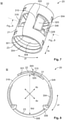
- Figures 1 and 2 show a first variant of the invention and Figures 3 to 19 show a second variant of the invention, wherein furthermore:
- the connecting device 1 given by way of example (cf. Figure 13 ) comprises a first or inner electrical terminal 10, the electrical ferrule 20 according to the invention, a second or outer electrical terminal 40 and a dielectric 30 between the inner terminal 10 and the outer terminal 40.
- the terminal 10 may be formed as a male or female terminal 10 and/or the terminal 40 may be formed as a shielding contact sleeve 40.
- Other forms of the connecting device 1 are of course possible.
- the connecting device 1 can be mounted or is mounted on an electrical cable 50 (also cable harness 50), in particular an HF cable 50 (electrical entity 5, in particular HF entity 5, as a preassembled electrical cable 5).
- the cable 50 may in this case be formed as a twinaxial cable ( Figures 1 and 2 ), a coaxial cable ( Figures 9, 10 , 13 and 14 ), etc.
- the cable 50 has at least centrally an inner conductor 51, an inner insulation 52, an outer conductor 53 and a protective sheath 54. Other configurations of the cable 50 can of course be used.
- the connecting device 1 may be mounted in an electrical connector 0 (indicated in Figure 13 by dashed lines), in particular an HF connector 0, preferably an HF data connector 0, such as a twinaxial connector (0), a coaxial connector 0, etc., for example in its connector housing.
- an electrical connector 0 indicated in Figure 13 by dashed lines
- an HF connector 0 preferably an HF data connector 0, such as a twinaxial connector (0), a coaxial connector 0, etc., for example in its connector housing.
- the first or inner terminal 10 comprises an electromechanical contact portion 11, a mechanical fastening portion 12 and an electromechanical crimping portion 13.
- the second or outer terminal 40 comprises an electromechanical contact portion 41, a mechanical fastening portion 42 and an electromechanical crimping portion 43.
- the ferrule 20, which preferably can be mounted radially on the outer conductor 53, in particular a shielding conductor 53, of the cable 50 and radially under the outer terminal 40, in particular the shielding contact sleeve 40 may be formed as a crimpable or non-crimpable ferrule 20.
- the ferrule 20 has centrally in its circumferential direction Ur a circumferential centre portion 23 and peripherally on both sides thereof in each case a flank 21, 22, which are possibly formed as crimping flanks 21, 22.
- This cross section of the ferrule 20 - substantially u-shaped or substantially v-shaped in its open state O (cf. Figures 3 to 5 ) and/or its premounting state V (first variant) on the cable 50 (cf. Figure 1 ), and/or substantially o-shaped in its mounting state M on the cable 50 (cf.
- Figure 2 Figures 7 to 10
- Figures 11 to 14 extends in addition to a material thickness of the ferrule 20 also substantially in axial direction Ar of the ferrule 20.
- the ferrule 20 Apart from comparatively small devices (304, 306, 308, 310, 318, 320, 328) extending in a radial direction Rr of the ferrule 20, the ferrule 20 preferably does not have a portion extending in radial direction Rr.
- At least one self-locking 201, 202 (first variant); 300 (second variant) of the ferrule 20 in circumferential direction Ur can be set up or is set up by means of the ferrule 20.
- a set-up self-locking 201, 202; 300 may in this case be effective in only one circumferential direction Ur (second variant, preferably a single self-locking 300) or in both circumferential directions Ur (first variant, preferably at least two self-lockings 201, 202), i.e. prevent an intrinsic movement of the ferrule 20 in at least one (that is to say precisely one or both) circumferential direction(s) Ur.
- the ferrule 20 is formed variably in a mounting diameter Md (both variants), kD (second variant) for a mounting state M (both variants), kM (second variant) on the cable 50.
- two free longitudinal end portions of the flanks 21, 22 that lie opposite one another in circumferential direction Ur may engage in one another in circumferential direction Ur (first variant) or be arranged one over the other in radial direction Rr (second variant) and possibly engage radially in one another.
- the first variant of the invention is for example suitable for different cable diameters (cf. above).
- the second variant of the invention can be used for example for a cable diameter that changes during a preassembly process of a cable 50 (cf. above).
- Figures 1 (premounting state V of the ferrule 20) and 2 ((final) mounting state M of the ferrule 20) show an embodiment of the first variant of the electrical ferrule 20 in use on an electrical twinaxial cable 50 for a twinaxial connecting device 1 (analogous to Figure 13 ); it is of course possible to use the first variant for another cable, such as for example a coaxial cable 50 (cf. Figures 3 to 14 ), etc.
- the ferrule 20 has in the present case precisely two self-lockings 201, 202 for an adaptation of the ferrule 20 to two different mounting diameters Md (cable diameters) of the ferrule 20 on the cable 50.
- the ferrule 20 may also have more than two self-lockings 201, 202 for a corresponding plurality of mounting diameters Md.
- the mounting diameters Md of the ferrule 20 can be set up successively in circumferential direction Ur, for which a first flank 21 has a single latching means 210, preferably formed as a latching projection 310, and a second flank 22 has a corresponding plurality of latching means 221, 222 (in the present case two), preferably formed as latching recesses 221, 222.
- the latching recesses 221, 222 are preferably set up in the flank 22 at the same axial position one behind the other in circumferential direction Ur.
- a first latching recess 221 merges seamlessly into a second latching recess 222.
- the two latching recesses 221, 222 are preferably formed substantially the same, in one respect from a mutual overlapping of the latching recesses 221, 222 and from an access to a first latching recess 221 in circumferential direction Ur for the latching projection 310.
- the latching projection 310 is formed in a mushroom-shaped manner and the latching recesses 221, 222 are formed analogous to a cap of the mushroom-shaped latching projection 310, which in the present case is formed as oval or circular.
- Other forms of the latching projection 310 and the latching recesses 221, 222 that at least partly complement one another can of course be used.
- the latching projection 310 fills in the respective latching recess 221, 222 substantially completely, once again apart from the aforementioned access.
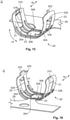
- Figures 3 to 19 show an embodiment of the second variant of the electrical ferrule 20 in use on an electrical coaxial cable 50 for a coaxial connecting device 1 ( Figure 13 ); it is of course possible to use the second variant on another cable, such as for example a twinaxial cable 50 (cf. Figures 1 and 2 ), etc.
- Figures 3 to 6 show the ferrule 20 in its open state O
- Figures 7 to 10 show the ferrule 20 in its crimped mounting state M
- Figures 11 to 14 show the ferrule 20 in its over-crimped and compressed mounting state kM.
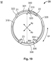
- Figures 15 to 19 show further embodiments of the invention.
- the ferrule 20 is preferably formed as a crimp ferrule 20, which is first crimped onto the cable 50. At a time thereafter, possibly after turning over a free end portion of the outer conductor 53 of the cable 50 onto it, a shielding contact sleeve 40 is crimped onto the cable 50 and the ferrule 20. That is to say that, during mounting of a connecting device 1 on the cable 50, the ferrule 20 is first itself crimped and then over-crimped with the shielding contact sleeve 40. First (mounting state M), the ferrule 20 on the cable 50 has a comparatively (cf. below) large mounting diameter Md.
- the ferrule 20 After the over-crimping (compressed mounting state kM), the ferrule 20 has a comparatively (see above) small compressed mounting diameter kD, since the ferrule 20 is/has been compressed in radial direction Rr by the over-crimping.
- the ferrule 20 In order that the ferrule 20 on the one hand can be mounted on the cable 50 (mounting state M) and on the other hand can be compressed in radial direction Rr on the cable 50 (compressed mounting state kM), the ferrule 20 has a single self-locking 300, which in addition also only acts in a single circumferential direction Ur, specifically against opening of the ferrule in the direction of its open state O. That is to say that in the mounting state M the ferrule 20 is fixed on the cable 50 with its substantially not increasable mounting diameter Md, but in such a way that the ferrule 20 is formed such that it can be reduced radially for the compressed mounting state kM, and the smaller compressed mounting diameter kD to be accepted therein, on the cable 50.
- the first flank 21 comprises a latching means 310, which is formed in particular as an outer hook 310 extending from the ferrule 20 in radial direction Rr.
- the second flank 22 comprises a latching means 320, which is formed in particular as an inner hook 320 projecting into the ferrule 20 in radial direction Rr.
- the ferrule 20 can be formed (premounting state V) or is formed in a double-layered manner in a circumferential portion in the mounting state M and of course also in the compressed mounting state kM.
- the outer hook 310 may be formed as a circumferential lug 310 extending tangentially and radially outwards from a curved plane of the first flank 21.
- the inner hook 320 may be formed as a radial hook extending tangentially and radially inwards from a curved plane of the second flank 22.
- two circumferential sides of the outer hook 310 and of the inner hook 320 corresponding to one another lie against one another preferably in a more or less form-fitting manner (tolerances) (cf. Figures 8 and 9 ), wherein the plane constituted thereby is preferably on the one hand not a tangent to the ferrule 20 and on the other hand does not lead through a centre of the ferrule 20.
- the plane cuts out a flat segment from a cross section of the ferrule 20 or a flat cylinder portion from the ferrule 20.
- an intrinsic freewheel 301 is set up in the ferrule 20 between the flanks 21, 22.
- the flanks 21, 22 can at first only be displaced in one circumferential direction Ur, specifically the direction of the compressed mounting state kM.
- the flanks 21, 22 can be moved with respect to one another both in the direction of the compressed mounting state kM and in the direction of the mounting state M.
- the intrinsic freewheel 301 is set up in particular as a sliding bearing or circumferential sliding bearing extending in circumferential direction Ur between the flanks 21, 22.
- the ferrule 20 may have in one flank 21, in both flanks 21, 22 and/or in the circumferential centre portion 23 at least one impedance compensating means 308, 318, 328 (in particular at least one, for example rectangular, passage 308, 318, 328 as an air slit, air cushion, etc.).
- impedance compensating means 308, 318, 328 are set up in the ferrule 20 as distributed regularly in circumferential direction Ur.
- the impedance compensating means 308 of the circumferential centre portion 23 may cover a greater circumferential portion than the respective impedance compensating means 318, 328 in the flanks 21, 22.
- a surface area of the impedance compensating means 308 of the circumferential centre portion 23 is substantially of the same size as the surface areas of the impedance compensating means 318, 328 of the flanks 21, 22 together, or, because of the intrinsic covering of the ferrule 20 in circumferential direction Ur in a region of the flanks 21, 22, somewhat smaller, possibly by about the amount of the coverage.
- An outer axial edge of the impedance compensating means 318 of the first flank 21 in the open state O and in circumferential direction Ur is preferably formed as the radial outer hook 310, that is to say as the latching means 310.
- an outer edge of the impedance compensating means 328 of the second flank 21 in the open state O and in circumferential direction Ur is preferably formed as the radial inner hook 320, that is to say as the latching means 320.
- the ferrule 20 possibly comprises in each case a stiffening bead 304 running in circumferential direction Ur.
- the ferrule 20 may have at least one fixing hook 306 projecting inwards in radial direction Rr.
- a fixing hook 306 is set up in the circumferential centre portion 23.
- such a fixing hook 306 is preferably set up in a corner section of the impedance compensating means 308 of the circumferential centre portion 23.
- two or four such fixing hooks 306 are set up in the corner sections of the impedance compensating means 308 of the circumferential centre portion 23.
- Other positions, in particular on/in one or both axial outer edges of the ferrule 20, can of course be used.
- the ferrule 20 may be formed as a non-crimpable, i.e. not plastically deformable, ferrule 20, but as a preferably only elastically and/or partly plastically deformable spring ferrule 20. That is to say that the two flanks 21, 22 are set up as spring flanks 21, 22 with respect to one another in radial direction Rr over the circumferential centre portion 23 in the ferrule 20.
- the ferrule 20 can however also be processed in a crimping process, and consequently can also be referred to as a crimp ferrule 20. This can be realized in both variants of the invention.
- a mixed formed between a crimpable ferrule 20 (cf. above) and a spring ferrule 20 can also be used.
- Figures 15 to 19 show three further embodiments.
- the ferrule 20 has in its open state O a cross section which is cross-sectionally pot-shaped or a u-shaped cross section (open on one side and rounded-rectangular).
- the ferrule 20 may, as also above, be formed as substantially circular, elliptical or oval.
- the ferrule 20 comprises between the impedance compensating means 308, 318; 308, 328 in circumferential direction Ur at least one, in particular two, stiffening beads 304 running in circumferential direction Ur.
- These stiffening beads 304 can be additionally or alternatively used in the case of the above, and also above stiffening beads 304 can be additionally or alternatively used in the case of these three further embodiments.
- the ferrule 20 in Figures 15 to 19 comprises an anticollision lug 322 projecting outwards in circumferential direction Ur on just one flank 22 for preventing the free circumferential ends of the flanks 21, 22 from colliding with one another during the crimping of the ferrule 20.
- the anticollision lug 322 may be formed as a comparatively narrow ( Figure 15 ) or a comparatively wide ( Figure 16 ) anticollision lug 322, which may be of advantage depending on a design of the ferrule 20 and/or a crimping process to be used.
- the anticollision lug 322 (cf. Figure 17 ) extends from a circumferential end of the flank 22 in circumferential direction Ur and possibly in the radial direction Rr.
- the anticollision lug 322 in the open state O, extends at first substantially outwards in the radial direction Rr and following that substantially in circumferential direction Ur; mixed forms thereof can of course be used.
- the anticollision lug 322 in the present case extends in the opposite way, specifically at first substantially in circumferential direction Ur and following that substantially inwards in radial direction Rr.
- the radial portion of the anticollision lug 322 comes to lie in circumferential direction Ur, wherein the circumferential portion of the anticollision lug 322 is bent over radially inwards.
- Other configurations of the anticollision lug 322, such as for example a ramp, etc., can of course be used.
- the anticollision lug 322 is actuated or triggered by a crimping tool, in particular a crimp indentor, in such a way that the anticollision lug 322 presses the first flank 21 radially under the second flank 22, so that as a consequence a beginning freewheel 301 of the ferrule 20 in circumferential direction Ur and as a consequence the self-locking 300 of the ferrule 20 can be set ( Figure 19 ).
- the crimping process works in such a way, and/or the anticollision lug 322 is formed in such a way, that in the mounting state M of the ferrule 20 the anticollision lug 322 has been swung into a corresponding impedance compensating means 318.
- Figure 18 shows a ferrule 20 without a fixing hook 306, which can likewise be used in the case of all the embodiments.
- the ferrule 20 may be formed in such a way that a self-locking of the ferrule 20 can be set up or is set up by means of the anticollision lug 322 and with a corresponding means of the ferrule 20, for example a means that partly complements it.
- a self-locking of the ferrule 20 can be set up or is set up by means of the anticollision lug 322 and with a corresponding means of the ferrule 20, for example a means that partly complements it.
- the anticollision lug 322 in such a way that it is locked in the mounting state M and/or compressed mounting state kM, for example for larger cable diameters, with a latching means of the flank 21, the latching means 310 or on/in the impedance compensating means 318.
- the anticollision lug 322 may be locked with the flank 21 in the compressed mounting state kM.
- the ferrule 20 does not have any stub crimping wings designed to butt against one another in circumferential direction Ur for assuming a function as a 'supporting sleeve', since the ferrule 20 is designed for different cable types or cable sizes.
- the material overlapping also prevents braided strands from being pulled into a crimping seam of the ferrule 20 during production of preassembled cables.
- the material of the ferrule 20 preferably has a (very) high tensile strength for assuming the function as a 'supporting sleeve' .
- the invention makes it possible for different cable sizes (cf. above) or cable types (cf. above) to fit for example into existing shielding contact sleeves. With such different cables, a conventional design of a ferrule could not always be closed, and consequently preassembly through to the end product could not be guaranteed.
- the ferrule 20 according to the invention can be crimped over such cable diameters (smaller to larger, in particular smaller). Since the crimping diameter or the crimping height for example of a shielding contact sleeve to be mounted thereafter defines an electrical performance of an end product and for example guarantees a good fit in a contact chamber in a housing, preassembly of the cable through to the functional end product is possible.
- the invention makes it possible to process, in particular to crimp, a range of diameters of cables with the same component parts, that is to say not only one specific cable size and/or one specific cable type.
Landscapes
- Details Of Connecting Devices For Male And Female Coupling (AREA)
- Coupling Device And Connection With Printed Circuit (AREA)
- Mechanical Coupling Of Light Guides (AREA)
- Connector Housings Or Holding Contact Members (AREA)
Abstract
Description
- The invention relates to an electrical ferrule, in particular an HF ferrule, for an electrical connecting device, in particular an HF data connecting device, preferably for the automotive sector. The invention also relates to an electrical contact means for an electrical contact device or an electrical connector, to an electrical connecting device for an electrical connector, to an electrical connector and to an electrical entity, preferably in each case for the automotive sector.
- In the electrical sector (electronics, electrical engineering, electrics, electrical energy technology, etc.) there are a large number of known electrical connector means or connector devices, socket connectors, pin connectors and/or hybrid connectors, etc. - referred to below as (electrical) connectors (also: mating connectors) - that serve for transmitting electrical currents, voltages, signals and/or data with a wide range of currents, voltages, frequencies and/or data rates. In the area of low, medium or high voltage and/or current, and in particular in the automotive sector, such connectors must ensure transmission at short notice of electrical power, signals and/or data in mechanically stressed, warm, possibly hot, contaminated, damp and/or chemically aggressive environments sustainably, repeatedly and/or after a comparatively long period of inactivity. Because the range of applications is wide, a large number of specially designed connectors are known.
- Such a connector, and possibly its associated housing (for example in the case of a connector means or a connector device) or higher-level housing (for example in the case of a connector device), can be installed on an electrical line, a cable, a cable harness, etc. - referred to below as a preassembled (electrical) cable (also: electrical entity) - , or on/in an electrical device or means, such as for example on/in a housing, on a leadframe, on a circuit board etc., of a (power) electrical, electrooptical or electronic component part or a corresponding assembly, etc. (electrical entity).
- If a connector (with/without a housing) is situated on a cable, a line or a cable harness, this is also called a flying-lead (plug-in) connector or a plug, a socket or a coupling; if it is situated on/in an electrical, electrooptical or electronic component, assembly etc., this is also called a connector device, such as for example a (built-in/attached) connector, a (built-in/attached) plug or a (built-in/attached) socket. Furthermore, a connector on such a device is often referred to as a (plug) holder, box header connector, pin strip or header. In the context of electrical energy technology (generating, converting, storing and transporting high-voltage electrical current within electricity grids, preferably with three-phase high-voltage transmission), owing to their relatively complex structure reference is made here to cable accessories.
- Such a connector must ensure faultless transmission of electricity, wherein mutually corresponding and partially complementary connectors (connectors and mating connectors) usually have locking devices and/or fastening devices for locking and/or fastening the connector on/in the mating connector, and vice versa, in a long-lasting but usually detachable fashion. - Furthermore, an electrical connecting device for a connector, for example comprising or at least having an actual contact means (terminal; usually formed as a single piece of material or integrally, for example a contact element, etc.) or a contact device (terminal; usually formed as many parts, two parts, a single part, a single piece of material or integrally, for example a one- or multi-part (crimp) contact device), must be held securely therein. In the case of an (already) preassembled electrical cable, such a connecting device may be provided as a connector (cf. above), that is to say without a housing, for example in a flying-lead manner.
- Efforts are continually being made to improve electrical connectors and their connecting devices, in particular because of miniaturization to make them more robust, design them more effectively and produce them at lower cost. For HF data connectors (HF: high-frequency, definition here: transmission frequencies greater than 3 to greater than 300 MHz and well into the GHz range (about 150 GHz)) other rules apply here than for conventional data connectors (definition here: transmission frequencies lower than about 3 MHz), since in particular the wave properties of electricity are evident in HF technology. - In particular because of their configuration and/or their final diameter on a cable, in particular an HF cable, a ferrule (supporting sleeve) has a significant influence on an impedance of a connecting device.
- Conventional ferrules of a specific type are only intended for use with a single cable type, for example from a single manufacturer, or only a single actual cable size (cable diameter of the inner layers, for example of a coaxial cable, a twinaxial cable, etc.). For other cable types or cable sizes, other types of ferrules must be used. - In addition to different cable diameters of two cable types, a changing cable diameter is problematic during a preassembly process of a cable. This is for example because of at least one mechanical property (finish, hardness, compressibility, elasticity, etc.) of the cable, in particular its comparatively great inner insulating layer. In addition, this is made more difficult because cables with the same diameter from different manufacturers have different properties, once again in particular in the insulating layers. In addition, there is the problem of the tolerances involved.
- It is an object of the invention to provide an improved, possibly HF-suitable, electrical ferrule, an improved, possibly HF-suitable, electrical connecting device and an improved, possibly HF-suitable, electrical connector, preferably for the automotive sector. Here, the ferrule should be designed for different cable diameters and/or be able to adapt itself to changing diameters of a cable during a preassembly process of the cable. Furthermore, it is intended that the ferrule, the connecting device and the connector can be produced at low cost in comparison with its later use and is of a simple construction and/or is easy to handle.
- The object of the invention is achieved by means of an electrical ferrule, in particular an HF ferrule, for an electrical connecting device, by means of an electrical contact means for an electrical contact device or an electrical connector, by means of an electrical connecting device for an electrical connector, by means of an electrical connector and by means of an electrical entity, preferably in each case for the automotive sector. - Advantageous developments, additional features and/or advantages of the invention arise from the dependent claims and the following description.
- The ferrule according to the invention merely comprises two flanks which extend in axial direction of the ferrule, lie opposite one another in radial direction of the ferrule and are connected to one another in the circumferential direction of the ferrule by way of a circumferential centre portion. According to the invention, at least one self-locking of the ferrule in the circumferential direction can be set up or is set up by means of the flanks, by means of which the ferrule is formed variably in a mounting diameter (also compressed mounting diameter) for its mounting state (also compressed mounting state) on an electrical cable, in particular an HF cable. - Here, the ferrule may be formed as a crimp ferrule, it then being possible to refer not only to a mounting diameter but also to a crimping height.
- Here, by analogy with the flanks, the circumferential portion of course likewise extends in axial direction, and, by analogy with the circumferential portion, the flanks extend according to a state of the ferrule (open state as opposed to premounting state, as opposed to mounting state and/or compressed mounting state), that is to say a position of its flanks, of course likewise in the circumferential direction. Furthermore, in a circumferential direction, a first flank merges into the circumferential centre portion and the circumferential centre portion merges into a second flank. Here, the circumferential centre portion may have a greater, equal or lesser stiffness and/or thickness as compared with a flank or both flanks.
- Here, an unrolled outer base area of the ferrule may be approximately or primarily formed as rectangular. The ferrule is preferably formed or constituted merely by a flat and/or thin layer of material, such as for example a metal sheet. Here, the ferrule may be punched or die-cut and subsequently possibly bent into shape. Apart from its actual purpose of mounting on a cable, the ferrule as such is formed as open at both its axial end faces (front and rear) both in its open state and its closed state. In an open state of the ferrule, its cross section is preferably substantially u-shaped or v-shaped. In a mounting state and/or compressed mounting state (cf. below) of the ferrule, its cross section is preferably substantially o-shaped.
- The ferrule is preferably formed as an integral ferrule. An integral form should be understood as meaning a form of the ferrule in which there is only a single component, which can only be divided by being destroyed. The component is produced from a single original piece (metal sheet, blank, etc.) and/or a single original compound (molten metal, polymer melt, etc.), which for its part is necessarily integral. It is internally held together by means of adhesion and/or cohesion. The ferrule itself may be formed from a metal, a metal alloy, a plastic or a plastic-metal composite. If the ferrule is formed from a plastic, it is preferably metallized on the inside and outside with a metal or metal alloy. The ferrule may additionally have at least one coating, deposition, galvanization, etc.
- By means of a specific self-locking of the ferrule in the circumferential direction, a setting of a specific mounting diameter of the ferrule possibly first takes place, wherein such a single self-locking can be formed by a single individual locking, for example of two latching means, or a plurality of individual lockings with for example two latching means in each case. That is to say that a self-locking may comprise a number of individual lockings, which may for example be set up as distributed between the flanks in axial direction and/or circumferential direction. That is also to say that, no matter with what number of individual lockings and/or latching means it can be set up or is set up, a self-locking correlates with a specific mounting diameter of the ferrule.
- A mounting diameter or a mounting inner diameter of the ferrule is understood as meaning at least one diameter. Here, in particular, primarily or substantially all mounting diameters or mounting inner diameters of the ferrule may be formed variably. - In particular, the ferrule as such does not have any further portion in axial direction that is connected to it as a single piece of material or integrally, such as for example an electromechanical contact portion provided indirectly or directly on it.
- It may be that the ferrule can be closed or is closed on the cable in the circumferential direction by means of its at least one self-locking. A set-up self-locking may be effective in just one circumferential direction or in both circumferential directions. If the set-up self-locking is effective in a single circumferential direction, the mounting diameter of the ferrule may possibly be further reduced or possibly further increased progressively over time.
- If the set-up self-locking is effective in both circumferential directions, as a result the mounting diameter is substantially fixed apart from a permanently elastic or plastic deformation of the ferrule. In a set-up self-locking, the two free longitudinal end portions of the flanks may engage in one another in the circumferential direction and/or be arranged one over the other in radial direction. Latching means of the first flank and the second flank that correspond to one another are formed in particular as partly complementing one another and/or form-fitting one another in certain portions.
- In a variant of the invention, the ferrule may have a multiplicity of self-lockings that can be set up, wherein a mounting diameter can be set up with an arbitrary self-locking of the self-lockings when setting up the ferrule on the cable (cf. cable ties). The ferrule may have precisely two or a specific multiplicity of self-lockings that can be set up, by means of which precisely two or the specific multiplicity of mounting diameters can be set up on the cable. Here, the self-lockings are preferably formed in such a way that they are effective in both circumferential directions. As already explained above, such self-lockings that can be set up are respectively constituted by a single individual locking or a plurality of individual lockings. Apart from a cable diameter to be set up, it may be that the self-lockings of the ferrule can be set up successively in the circumferential direction by means of the flanks.
- For the self-lockings, the first flank may have a single latching means and the second flank may have precisely two or a/the specific multiplicity of latching means. The latching means of the first flank may be formed as a latching projection, which is formed by a free circumferential portion from the first flank. Thus, the latching projection may be formed for example in an I-shaped, t-shaped, o-shaped, mushroom-shaped, etc. manner.
- The latching means of the second flank may be configured as latching recesses in the second flank, wherein the latching recesses preferably merge uninterruptedly one into the other. Here, by analogy with the positive latching projection of the first flank, the latching recess is set up as a corresponding negative in the second flank. Furthermore, the latching recesses that merge uninterruptedly one into the other are directly in fluid communication. And, of course, the latching means that merge uninterruptedly one into the other of the second flank are set up in a row in the circumferential direction.
- At least in a mounting state of the ferrule on the cable and apart from an extent of the ferrule in axial direction and its material thickness in radial direction, the latching projection (latching means) and/or the latching recesses (latching means) extend exclusively in the circumferential direction. In addition, or as an alternative, in this case the latching projection (latching means) may fill in a corresponding latching recess (latching means) substantially completely (form fit).
- In a variant of the invention, the ferrule may preferably have precisely one self-locking that can be set up or is set up, by means of which preferably precisely one substantially maximum mounting diameter (not: compressed mounting diameter) in a mounting state of the ferrule can be set up or is set up on the cable. Here, the self-locking is preferably formed in such a way that it is effective in a single circumferential direction. As already explained above, such a self-locking that can be set up may be respectively constituted by a single individual locking or a plurality of individual lockings. The self-locking that can be set up or is set up may be effective in the ferrule in such a way that, in the mounting state of the ferrule on the cable, on the one hand the maximum mounting diameter of the ferrule cannot be increased again and on the other hand however the maximum mounting diameter of the ferrule can still be reduced (in the direction of its compressed mounting diameter).
- As a result, it is for example possible to set an impedance of an electrical connecting device having the ferrule, for example on an outer conductor of a coaxial cable or a twinaxial cable, in a region of the ferrule only in a final mounting step, for example the crimping of a shielding contact sleeve. This takes place for example by a crimping diameter for example of the shielding contact sleeve. This makes it possible for an end product to meet the performance requirements. A material of the ferrule, such as for example a preferably uncoated high-grade steel, has in particular a high to very high tensile strength in order to assume a function of the ferrule as a supporting sleeve. The material thickness is preferably less than or substantially equal to: 0.35 mm, 0.3 mm, 0.25 mm, 0.2 mm, 0.19 mm, 0.18 mm, 0.17 mm, 0.16 mm or 0.15 mm.
- The ferrule may also be formed in such a way that, starting from its form in the mounting state, it can be radially compressed for a compressed mounting state on the cable, for which the ferrule preferably can be formed or is formed in a double-layered manner in a circumferential portion. That is to say for example that a form of the ferrule that is closed in the circumferential direction can be closed further, whereby an inner diameter and possibly also an outer diameter of the ferrule are reduced. In addition, or as an alternative, in the mounting state, an intrinsic freewheel (clearance) is set up in the ferrule between the flanks, in which the flanks are set up so as to be displaceable relative to one another, preferably initially in only one circumferential direction.
- The flanks may respectively have a latching means for the self-locking of the ferrule, wherein the self-locking is set up in the mounting state of the ferrule. Furthermore, the latching means may only be effective against an increase in the mounting diameter of the ferrule. Furthermore, the latching means may allow a reduction of the mounting diameter of the ferrule. That is to say that the latching means constitute a means of stopping a mutual displaceability of the flanks in the circumferential direction in such a way that a displaceability of the flanks in the direction of a reduction of the mounting diameter of the ferrule is still possible.
- The latching means of a first flank may be formed as a radial outer hook and the latching means of a second flank may be formed as a radial inner hook. That is to say that the outer hook is formed as a latching hook extending radially outwards from the first flank and the inner hook is formed as a latching hook extending radially inwards from the second flank. - During the initial transfer of the ferrule from its mounting state into its compressed mounting state, the latching means are released from one another. The compressed mounting state of the ferrule can be adopted for example when a contact means, such as for example a shielding contact sleeve, is mounted over the ferrule, in particular is crimped.
- The intrinsic freewheel may be set up as a sliding bearing extending in the circumferential direction (circumferential sliding bearing, not a radial sliding bearing with a rotating bearing counterpart) between the flanks. Furthermore, in the mounting state and/or compressed mounting state, the latching means may be substantially in line with a corresponding outer side of the ferrule. That is to say that a height of the latching means lies in a region of a material thickness of the ferrule.
- The ferrule may be formed as an exclusively elastically, partially plastically or substantially plastically deformable ferrule. In particular, the ferrule may be formed as a substantially elastically and/or partly plastically deformable, mechanically prestressable spring ferrule. As a result, a turned-over longitudinal end portion of a shielding conductor can be made to bear against the spring ferrule in a radially outwardly prestressed manner. - The ferrule may have a stiffening bead preferably running substantially in the circumferential direction (cf. below).
- In one embodiment, an impedance compensating means may be arranged in at least one flank or in the respective flank. In addition or as an alternative, an impedance compensating means may be arranged in the circumferential centre portion. A respective impedance compensating means is set up in particular as a substantially rectangular passage (air gap, air cushion) in the corresponding flank and/or the circumferential centre portion. Here, an impedance compensating means, in particular the passage, is formed and dimensioned in such a way that an impedance of the ferrule is improved. Being formed in this way helps to adjust the low impedance zone caused by a compression of the cable by a dielectric air gap or a dielectric air cushion in the barrel of the ferrule. As a result, an HF performance of an HF plug-in connection can be improved.
- In the ferrule, in particular in the circumferential centre portion, at least one fixing hook or arresting hook that protrudes inwards in radial direction may be provided. By means of such a fixing hook, the ferrule can be secured on the cable during a preassembly of the cable. Here, a plurality of fixing hooks may be provided in corner sections of the impedance compensating means of the circumferential centre portion. Preferably, two or four such fixing hooks are set up in the ferrule. It is preferred here that the ferrule is formed in such a way that, during the crimping of the ferrule, the fixing hooks are provided with support by a crimping tool, in particular a crimp anvil. That is to say that it is also preferred that the impedance compensating means is dimensioned in such a way that it does not protrude beyond the crimping tool during the crimping of the ferrule.
- An edge of the impedance compensating means of a/the first flank may be formed as the latching means of the first flank. The latching means of the first flank may be formed as a circumferential lug which extends radially outwards from a curved plane of the first flank and possibly has a tangential part. An edge of the impedance compensating means of a/the second flank may be formed as the latching means of the second flank. The latching means of the second flank may also be formed as a radial hook which extends radially inwards from a curved plane of the second flank and possibly has a tangential part. In the mounting state, the radial hook sits with a preferably outer axial side, in particular in a form-fitting manner, on a preferably inner axial side of the circumferential lug substantially in a form-fitting manner. The axial side respectively lying opposite in the circumferential direction is substantially free.
- In an open state of the ferrule, the circumferential centre portion may have a smaller radius of curvature than a circumferential portion of a flank directly adjoining in a circumferential direction. This may of course also concern both flanks. As a result, the ferrule is given a cross section which in a front view is cross-sectionally pot-shaped or a u-shaped cross section with a comparatively straight or comparatively (with respect to the directly adjoining circumferential portion of the flank) less curved crosspiece between its two legs. In other embodiments, the ferrule may be formed in a cross section or a front view in the form of an arc of a circle or in the form of an arc of an ellipse. An arc ring portion of an oval can of course likewise be used.
- The flanks may be formed substantially straight or slightly inwardly curved in their flank circumferential centre portions. That is to say for example that such a flank circumferential centre portion is arranged substantially tangentially with respect to a circumferential portion directly adjoining in the direction of the circumferential centre portion in the circumferential direction. The ferrule may have an anticollision lug projecting outwards in the circumferential direction on just one flank. The anticollision lug serves for preventing the free circumferential ends of the flanks from colliding with one another during the crimping of the ferrule. During the crimping of the ferrule, the first flank can be pressed radially under the second flank by the anticollision lug, which is for example actuated/triggered by a crimping tool. Furthermore, a self-locking of the ferrule in the circumferential direction can be set up or is set up by means of the anticollision lug for the / in the mounting state and/or compressed mounting state.
- In particular, a stiffening bead is set up in an axial end portion or stiffening beads, which are preferably formed as elongated stiffening beads, are set up in both axial end portions. Here it is preferred that the corresponding stiffening bead extends from one flank over the circumferential centre portion and past the impedance compensating means of the circumferential centre portion into the other flank, wherein the two longitudinal ends of the stiffening bead lie within the flanks. In particular, it is preferred that the ferrule is formed for its intended use in such a way that one circumferential end of such a stiffening bead in the compressed mounting state does not come into mechanical contact with a corresponding circumferential end of a flank (discontinuous diameter reduction).
- Furthermore, a circumferential transitional region from the circumferential centre portion into a flank may have a stiffening bead axially level with an impedance compensating means, that is to say in particular between the impedance compensating means of the circumferential centre portion and a corresponding impedance compensating means of the flank. Here, at least one, in particular two or a plurality of such stiffening beads may be set up in the circumferential transitional region, in particular symmetrically with respect to an axially central circumferential centre line; this may also apply to the stiffening beads above. Such a stiffening bead may begin on/in an impedance compensating means and extend possibly onto/into the impedance compensating means directly adjacent to it in the circumferential direction. Apart from an open interior space of the ferrule, two impedance compensating means that are directly adjacent in the circumferential direction may in this case be in fluid communication by way of at least one stiffening bead.
- The contact means according to the invention has an electromechanical contact portion and a ferrule formed as a single piece of material or integrally with it, wherein the ferrule is formed according to the invention. - The connecting device according to the invention has at least one electrical terminal and a ferrule or a contact means, wherein the ferrule or the contact means is formed according to the invention.
- Here, the connecting device may be formed as a coaxial connecting device, a twinaxial connecting device (in each case in three parts), etc. A terminal may be formed as an inner male terminal or an inner female terminal. Furthermore, a terminal may be formed as an outer shielding contact sleeve. Preferably, the connecting device has an inner terminal and an outer terminal.
- The connector according to the invention has a connector housing, a ferrule, a contact means or a connecting device, wherein the ferrule, the contact means or the connecting device is formed according to the invention. Here, the connector may be formed as a coaxial connector, a twinaxial connector, etc. - The entity according to the invention has a contact means, a connecting device or a connector, wherein the contact means, the connecting device or the connector is formed according to the invention.
- Here, the entity may have, for example in addition to an entity housing, also at least one mechanical, electrical, electronic, optical and/or fluid means or device. Such an entity may for example (also) be formed as a means, a device, a preassembled cable, a subassembly, a circuit board, a component part, a module, an appliance, an apparatus, a unit, an installation, a system, etc.
- The invention is explained more specifically below on the basis of exemplary embodiments with reference to the attached schematic and not-to-scale drawing. Portions, elements, components, units, component parts and/or diagrams which have an identical, unambiguous or analogous form and/or function are designated with the same reference signs in the description of the figures (see below), the list of reference signs, the patent claims and in the figures of the drawing. A possible alternative which is not explained in the description of the invention (see above), is not shown in the drawing and/or is not exhaustive, a static and/or kinematic reversal, a combination etc. of the exemplary embodiments of the invention or a component part, a diagram, a unit, a component, an element or a portion thereof can also be derived from the list of reference signs and/or the description of the figures.
- In the invention, a feature (portion, element, component, unit, component part, function, size, etc.) may be embodied positively, i.e. is present, or negatively, i.e. is absent. In this specification (description (description of the invention (see above), description of the figures (see below)), list of reference signs, patent claims, drawing), a negative feature is not explicitly explained as a feature when it is not of significance according to the invention that it is absent. That is to say that the invention which is actually created, rather than one construed according to the prior art, consists in omitting this feature.
- A feature of this specification may be applied not only in a stated way but also in a different way (isolation, combination, replacement, addition, alone, omission, etc.). In particular, it is possible to replace, add or omit a feature in the patent claims and/or the description on the basis of a reference sign and a feature associated therewith, or vice versa, in the description, the list of reference signs, the patent claims and/or the drawing. In addition, a feature may consequently be explained and/or specified more specifically in a patent claim.
- The features of the description can (given the (initially largely unknown) prior art) also be interpreted as optional features; that is to say that any feature can be considered to be an optional, arbitrary or preferred, i.e. non-binding feature. It is thus possible to disassociate a feature, possibly including its periphery, from an exemplary embodiment, wherein this feature can then be transferred to a generalized inventive concept. The absence of a feature (negative feature) in an exemplary embodiment shows that the feature is optional with respect to the invention. Furthermore, a technical term for a feature can also be interpreted as a generic term for the feature (possibly further hierarchically disaggregated into lower-level terms, etc.), as a result of which a generalization of the feature is possible, for example taking into consideration an equivalent effect and/or equivalence.
- In the figures, provided just by way of example,
Figures 1 and 2 show a first variant of the invention andFigures 3 to 19 show a second variant of the invention, wherein furthermore: -
Figures 1 and 2 show in perspective views an embodiment of an electrical ferrule according to the invention that is variable in its mounting diameter, according to the first variant, andFigure 1 shows a premounting state andFigure 2 shows a mounting state of the ferrule on an electrical cable; -
Figures 3 to 6 show in perspective views (Figures 3 and 4 ) and front views (Figures 5 and 6 (in section)) an embodiment of an electrical ferrule that is variable in its mounting diameter, according to the second variant, whereinFigures 3 to 6 show the ferrule in its open state; -
Figures 7 to 10 show the ferrule according to the invention in its mounting state without a cable (Figures 7 and 8 (in section)) and on an electrical cable (Figures 9 and 10 (in section)), whereinFigures 7 and9 respectively show a perspective view andFigures 8 and10 respectively show a front view; -
Figures 11 to 14 show the ferrule according to the invention in its compressed mounting state without a cable (Figures 11 and 12 (in section)) and on the cable (Figures 13 and 14 (in section)), whereinFigures 11 and13 respectively show a perspective view andFigures 12 and14 respectively show a front view; and -
Figures 15 to 19 show in perspective views (Figures 15 and 16 ) and front views (Figures 17 to 19 (in section)) three further embodiments of the ferrule, whereinFigures 15 to 17 show the ferrule in its open state,Figure 18 shows the ferrule during its mounting andFigure 19 shows the ferrule in its mounting state. - The invention is explained more specifically below on the basis of exemplary embodiments of embodiments of two variants (variant one:
Figures 1 and 2 , variant two:Figures 3 to 19 ) of anelectrical ferrule 20, in particular anHF ferrule 20, for an electrical connectingdevice 1, in particular an HFdata connecting device 1, preferably for the automotive sector. Although the invention is more specifically described and illustrated in more detail by preferred exemplary embodiments, the invention is not restricted by the exemplary embodiments disclosed, but is of a more fundamental nature. - Other variations can be derived from this and/or from the above (description of the invention) without departing from the scope of protection of the invention. The invention can be used generally in the electrical sector in the case of an electrical entity (cf. above). An exception here is ground-based electrical energy technology. Only those spatial portions of a subject of the invention that are necessary for an understanding of the invention are shown in the drawing. Terms such as connector and mating connector, terminal and mating terminal, etc. should be interpreted as synonyms, that is to say may be mutually interchangeable.
- The connecting
device 1 given by way of example (cf.Figure 13 ) comprises a first or innerelectrical terminal 10, theelectrical ferrule 20 according to the invention, a second or outerelectrical terminal 40 and a dielectric 30 between theinner terminal 10 and theouter terminal 40. Here, the terminal 10 may be formed as a male orfemale terminal 10 and/or the terminal 40 may be formed as ashielding contact sleeve 40. Other forms of the connectingdevice 1 are of course possible. - The connecting
device 1 can be mounted or is mounted on an electrical cable 50 (also cable harness 50), in particular an HF cable 50 (electrical entity 5, inparticular HF entity 5, as a preassembled electrical cable 5). Thecable 50 may in this case be formed as a twinaxial cable (Figures 1 and 2 ), a coaxial cable (Figures 9, 10 ,13 and 14 ), etc. In the present case, thecable 50 has at least centrally aninner conductor 51, aninner insulation 52, anouter conductor 53 and aprotective sheath 54. Other configurations of thecable 50 can of course be used. The connectingdevice 1 may be mounted in an electrical connector 0 (indicated inFigure 13 by dashed lines), in particular anHF connector 0, preferably anHF data connector 0, such as a twinaxial connector (0), acoaxial connector 0, etc., for example in its connector housing. - In the present case (cf.
Figure 13 ), the first orinner terminal 10 comprises anelectromechanical contact portion 11, amechanical fastening portion 12 and an electromechanical crimpingportion 13. Another form can of course be used. Furthermore, the second orouter terminal 40 comprises anelectromechanical contact portion 41, amechanical fastening portion 42 and an electromechanical crimpingportion 43. Once again, another form can of course be used. Here, theferrule 20, which preferably can be mounted radially on theouter conductor 53, in particular a shieldingconductor 53, of thecable 50 and radially under theouter terminal 40, in particular the shieldingcontact sleeve 40, may be formed as a crimpable ornon-crimpable ferrule 20. - The
ferrule 20 has centrally in its circumferential direction Ur acircumferential centre portion 23 and peripherally on both sides thereof in each case aflank flanks Figures 3 to 5 ) and/or its premounting state V (first variant) on the cable 50 (cf.Figure 1 ), and/or substantially o-shaped in its mounting state M on the cable 50 (cf.Figure 2 ,Figures 7 to 10 ) and/or its compressed mounting state kM (second variant) on the cable 50 (Figures 11 to 14 ) - extends in addition to a material thickness of theferrule 20 also substantially in axial direction Ar of theferrule 20. Apart from comparatively small devices (304, 306, 308, 310, 318, 320, 328) extending in a radial direction Rr of theferrule 20, theferrule 20 preferably does not have a portion extending in radial direction Rr. - According to the invention, at least one self-locking 201, 202 (first variant); 300 (second variant) of the
ferrule 20 in circumferential direction Ur can be set up or is set up by means of theferrule 20. A set-up self-locking 201, 202; 300 may in this case be effective in only one circumferential direction Ur (second variant, preferably a single self-locking 300) or in both circumferential directions Ur (first variant, preferably at least two self-lockings 201, 202), i.e. prevent an intrinsic movement of theferrule 20 in at least one (that is to say precisely one or both) circumferential direction(s) Ur. - As a result, the
ferrule 20 is formed variably in a mounting diameter Md (both variants), kD (second variant) for a mounting state M (both variants), kM (second variant) on thecable 50. For this, two free longitudinal end portions of theflanks -
Figures 1 (premounting state V of the ferrule 20) and 2 ((final) mounting state M of the ferrule 20) show an embodiment of the first variant of theelectrical ferrule 20 in use on anelectrical twinaxial cable 50 for a twinaxial connecting device 1 (analogous toFigure 13 ); it is of course possible to use the first variant for another cable, such as for example a coaxial cable 50 (cf.Figures 3 to 14 ), etc. Theferrule 20 has in the present case precisely two self-lockings ferrule 20 to two different mounting diameters Md (cable diameters) of theferrule 20 on thecable 50. Of course, theferrule 20 may also have more than two self-lockings - The mounting diameters Md of the
ferrule 20 can be set up successively in circumferential direction Ur, for which afirst flank 21 has a single latching means 210, preferably formed as a latchingprojection 310, and asecond flank 22 has a corresponding plurality of latching means 221, 222 (in the present case two), preferably formed as latchingrecesses flank 22 at the same axial position one behind the other in circumferential direction Ur. Here, afirst latching recess 221 merges seamlessly into asecond latching recess 222. The two latchingrecesses first latching recess 221 in circumferential direction Ur for the latchingprojection 310. - In the present case, the latching
projection 310 is formed in a mushroom-shaped manner and the latching recesses 221, 222 are formed analogous to a cap of the mushroom-shapedlatching projection 310, which in the present case is formed as oval or circular. Other forms of the latchingprojection 310 and the latching recesses 221, 222 that at least partly complement one another can of course be used. In the possible mounting states M (in the present case two), the latchingprojection 310 fills in therespective latching recess -
Figures 3 to 19 show an embodiment of the second variant of theelectrical ferrule 20 in use on an electricalcoaxial cable 50 for a coaxial connecting device 1 (Figure 13 ); it is of course possible to use the second variant on another cable, such as for example a twinaxial cable 50 (cf.Figures 1 and 2 ), etc. Here,Figures 3 to 6 show theferrule 20 in its open state O,Figures 7 to 10 show theferrule 20 in its crimped mounting state M andFigures 11 to 14 show theferrule 20 in its over-crimped and compressed mounting state kM.Figures 15 to 19 show further embodiments of the invention. - That is to say that the
ferrule 20 is preferably formed as acrimp ferrule 20, which is first crimped onto thecable 50. At a time thereafter, possibly after turning over a free end portion of theouter conductor 53 of thecable 50 onto it, ashielding contact sleeve 40 is crimped onto thecable 50 and theferrule 20. That is to say that, during mounting of a connectingdevice 1 on thecable 50, theferrule 20 is first itself crimped and then over-crimped with the shieldingcontact sleeve 40. First (mounting state M), theferrule 20 on thecable 50 has a comparatively (cf. below) large mounting diameter Md. After the over-crimping (compressed mounting state kM), theferrule 20 has a comparatively (see above) small compressed mounting diameter kD, since theferrule 20 is/has been compressed in radial direction Rr by the over-crimping. - In order that the
ferrule 20 on the one hand can be mounted on the cable 50 (mounting state M) and on the other hand can be compressed in radial direction Rr on the cable 50 (compressed mounting state kM), theferrule 20 has a single self-locking 300, which in addition also only acts in a single circumferential direction Ur, specifically against opening of the ferrule in the direction of its open state O. That is to say that in the mounting state M theferrule 20 is fixed on thecable 50 with its substantially not increasable mounting diameter Md, but in such a way that theferrule 20 is formed such that it can be reduced radially for the compressed mounting state kM, and the smaller compressed mounting diameter kD to be accepted therein, on thecable 50. - For this, the
first flank 21 comprises a latching means 310, which is formed in particular as anouter hook 310 extending from theferrule 20 in radial direction Rr. Furthermore, for this thesecond flank 22 comprises a latching means 320, which is formed in particular as aninner hook 320 projecting into theferrule 20 in radial direction Rr. In order that the latching means 310, 320 can lock on one side, theferrule 20 can be formed (premounting state V) or is formed in a double-layered manner in a circumferential portion in the mounting state M and of course also in the compressed mounting state kM. - The
outer hook 310 may be formed as acircumferential lug 310 extending tangentially and radially outwards from a curved plane of thefirst flank 21. Theinner hook 320 may be formed as a radial hook extending tangentially and radially inwards from a curved plane of thesecond flank 22. In the mounting state M, two circumferential sides of theouter hook 310 and of theinner hook 320 corresponding to one another lie against one another preferably in a more or less form-fitting manner (tolerances) (cf.Figures 8 and9 ), wherein the plane constituted thereby is preferably on the one hand not a tangent to theferrule 20 and on the other hand does not lead through a centre of theferrule 20. The plane cuts out a flat segment from a cross section of theferrule 20 or a flat cylinder portion from theferrule 20. - In the mounting state M and in the direction of the compressed mounting state kM in circumferential direction Ur, an
intrinsic freewheel 301 is set up in theferrule 20 between theflanks flanks flanks intrinsic freewheel 301 is set up in particular as a sliding bearing or circumferential sliding bearing extending in circumferential direction Ur between theflanks - Furthermore, the
ferrule 20 may have in oneflank 21, in bothflanks circumferential centre portion 23 at least one impedance compensating means 308, 318, 328 (in particular at least one, for example rectangular,passage ferrule 20 as distributed regularly in circumferential direction Ur. - Here, the impedance compensating means 308 of the
circumferential centre portion 23 may cover a greater circumferential portion than the respective impedance compensating means 318, 328 in theflanks circumferential centre portion 23 is substantially of the same size as the surface areas of the impedance compensating means 318, 328 of theflanks ferrule 20 in circumferential direction Ur in a region of theflanks - An outer axial edge of the impedance compensating means 318 of the
first flank 21 in the open state O and in circumferential direction Ur is preferably formed as the radialouter hook 310, that is to say as the latching means 310. By analogy to this, an outer edge of the impedance compensating means 328 of thesecond flank 21 in the open state O and in circumferential direction Ur is preferably formed as the radialinner hook 320, that is to say as the latching means 320. - Furthermore, axially before and/or after the impedance compensating means 308, 318, 328, that is to say along the corresponding impedance compensating means 308, 318, 328, theferrule 20 possibly comprises in each case a stiffeningbead 304 running in circumferential direction Ur. - Furthermore, the
ferrule 20 may have at least one fixinghook 306 projecting inwards in radial direction Rr. Preferably, such afixing hook 306 is set up in thecircumferential centre portion 23. Furthermore, such afixing hook 306 is preferably set up in a corner section of the impedance compensating means 308 of thecircumferential centre portion 23. In particular, two or four such fixing hooks 306 are set up in the corner sections of the impedance compensating means 308 of thecircumferential centre portion 23. Other positions, in particular on/in one or both axial outer edges of theferrule 20, can of course be used. - According to the invention, the
ferrule 20 may be formed as a non-crimpable, i.e. not plastically deformable,ferrule 20, but as a preferably only elastically and/or partly plasticallydeformable spring ferrule 20. That is to say that the twoflanks circumferential centre portion 23 in theferrule 20. Here, theferrule 20 can however also be processed in a crimping process, and consequently can also be referred to as acrimp ferrule 20. This can be realized in both variants of the invention. Furthermore, a mixed formed between a crimpable ferrule 20 (cf. above) and aspring ferrule 20 can also be used. -
Figures 15 to 19 show three further embodiments. Here, by contrast with above, theferrule 20 has in its open state O a cross section which is cross-sectionally pot-shaped or a u-shaped cross section (open on one side and rounded-rectangular). In the mounting state M (cf.Figure 19 ), theferrule 20 may, as also above, be formed as substantially circular, elliptical or oval. - Furthermore, theferrule 20 comprises between the impedance compensating means 308, 318; 308, 328 in circumferential direction Ur at least one, in particular two, stiffeningbeads 304 running in circumferential direction Ur. These stiffeningbeads 304 can be additionally or alternatively used in the case of the above, and also above stiffeningbeads 304 can be additionally or alternatively used in the case of these three further embodiments. - Furthermore, the
ferrule 20 inFigures 15 to 19 comprises ananticollision lug 322 projecting outwards in circumferential direction Ur on just oneflank 22 for preventing the free circumferential ends of theflanks ferrule 20. Here, theanticollision lug 322 may be formed as a comparatively narrow (Figure 15 ) or a comparatively wide (Figure 16 )anticollision lug 322, which may be of advantage depending on a design of theferrule 20 and/or a crimping process to be used. Here it is preferred to provide theanticollision lug 322 on thatflank 22 on which the inwardly directed latching means 320 is also formed. - In the open state O of the
ferrule 20, the anticollision lug 322 (cf.Figure 17 ) extends from a circumferential end of theflank 22 in circumferential direction Ur and possibly in the radial direction Rr. In the present case, in the open state O, theanticollision lug 322 extends at first substantially outwards in the radial direction Rr and following that substantially in circumferential direction Ur; mixed forms thereof can of course be used. And, furthermore, in the mounting state M, theanticollision lug 322 in the present case extends in the opposite way, specifically at first substantially in circumferential direction Ur and following that substantially inwards in radial direction Rr. Here, the radial portion of theanticollision lug 322 comes to lie in circumferential direction Ur, wherein the circumferential portion of theanticollision lug 322 is bent over radially inwards. - Other configurations of theanticollision lug 322, such as for example a ramp, etc., can of course be used. - During the crimping of the ferrule 20 (cf.
Fig. 18 ), theanticollision lug 322 is actuated or triggered by a crimping tool, in particular a crimp indentor, in such a way that theanticollision lug 322 presses thefirst flank 21 radially under thesecond flank 22, so that as a consequence abeginning freewheel 301 of theferrule 20 in circumferential direction Ur and as a consequence the self-locking 300 of theferrule 20 can be set (Figure 19 ). Here it is preferred that the crimping process works in such a way, and/or theanticollision lug 322 is formed in such a way, that in the mounting state M of theferrule 20 theanticollision lug 322 has been swung into a correspondingimpedance compensating means 318. - Furthermore,Figure 18 shows aferrule 20 without a fixinghook 306, which can likewise be used in the case of all the embodiments. - Furthermore, the
ferrule 20 may be formed in such a way that a self-locking of theferrule 20 can be set up or is set up by means of theanticollision lug 322 and with a corresponding means of theferrule 20, for example a means that partly complements it. Here it is possible for example to form theanticollision lug 322 in such a way that it is locked in the mounting state M and/or compressed mounting state kM, for example for larger cable diameters, with a latching means of theflank 21, the latching means 310 or on/in theimpedance compensating means 318. In particular, in such embodiments, theanticollision lug 322 may be locked with theflank 21 in the compressed mounting state kM. - By means of the self-locking 201, 202; 300, springing back of the
ferrule 20, preferably produced from a stainless steel, or theflanks ferrule 20 does not have any stub crimping wings designed to butt against one another in circumferential direction Ur for assuming a function as a 'supporting sleeve', since theferrule 20 is designed for different cable types or cable sizes. With respect to comparable, conventional ferrules, it is preferred to reduce theferrule 20 in its material thickness to about 20% to 35%, in particular to about 30%, to compensate for the material overlapping in thefreewheel 310. The material overlapping also prevents braided strands from being pulled into a crimping seam of theferrule 20 during production of preassembled cables. The material of theferrule 20 preferably has a (very) high tensile strength for assuming the function as a 'supporting sleeve' . - The invention makes it possible for different cable sizes (cf. above) or cable types (cf. above) to fit for example into existing shielding contact sleeves. With such different cables, a conventional design of a ferrule could not always be closed, and consequently preassembly through to the end product could not be guaranteed. The
ferrule 20 according to the invention can be crimped over such cable diameters (smaller to larger, in particular smaller). Since the crimping diameter or the crimping height for example of a shielding contact sleeve to be mounted thereafter defines an electrical performance of an end product and for example guarantees a good fit in a contact chamber in a housing, preassembly of the cable through to the functional end product is possible. - The invention makes it possible to process, in particular to crimp, a range of diameters of cables with the same component parts, that is to say not only one specific cable size and/or one specific cable type. -
- 0
- (electrical) (HF) connector
- 1
- (electrical) (HF) connecting device
- 5
- (electrical) (HF) entity as a preassembled electrical cable
- 10
- (first/inner, electrical) (HF) terminal
- 11
- (electromechanical) contact portion
- 12
- (mechanical) fastening portion
- 13
- (electromechanical) crimping portion
- 20
- (electrical) (HF) ferrule
- 21
- (first) flank
- 22
- (second) flank
- 23
- circumferential centre portion
- 29
- carrier strip
- 30
- dielectric
- 40
- (second/outer, electrical) (HF) terminal
- 41
- (electromechanical) contact portion
- 42
- (mechanical) fastening portion
- 43
- (electromechanical) crimping portion
- 50
- (electrical) (HF) cable
- 51
- inner conductor
- 52
- inner insulation
- 53
- outer conductor
- 54
- protective sheath
- 201
- (first) self-locking (first variant)
- 202
- (second) self-locking (first variant)
- 210
- latching means of the
flank 21 - 221
- (first) latching means of the
flank 22 - 222
- (second) latching means of the
flank 22 - 300
- (single) self-locking (second variant)
- 301
- freewheel in circumferential direction Ur
- 304
- stiffening bead
- 306
- fixing hook
- 308
- impedance compensating means
- 310
- latching means of the
flank 21 - 318
- impedance compensating means
- 320
- latching means of the
flank 22 - 322
- anticollision lug
- 328
- impedance compensating means
- O
- open state of the
ferrule 20 - V
- premounting state of the ferrule 20 (first variant)
- M
- mounting state of the
ferrule 20 - Md
- mounting diameter of the
ferrule 20 in the mounting state M - kM
- compressed mounting state (only second variant)
- kD
- compressed mounting diameter of the
ferrule 20 in the compressed mounting state kM - Ar
- axial direction of connecting
device 1,ferrule 20 - Rr
- radial direction of connecting
device 1,ferrule 20 - Ur
- circumferential direction of connecting
device 1,ferrule 20
Claims (15)
- Electrical ferrule (20), in particular HF ferrule (20), for an electrical connecting device (1), in particular an HF data connecting device (1), preferably for the automotive sector, comprisingtwo flanks (21, 22), which extend in axial direction (Ar) of the ferrule (20), lie opposite one another in radial direction (Rr) of the ferrule (20) and are connected to one another in circumferential direction (Ur) of the ferrule (20) by way of a circumferential centre portion (23), characterized in thatat least one self-locking (201, 202; 300) of the ferrule (20) in circumferential direction (Ur) can be set up or is set up by means of the flanks (21, 22), by means of which the ferrule (20) is formed variably in a mounting diameter (Md, kD) for its mounting state (M, kM) on an electrical cable (50), in particular an HF cable (50).
- Electrical ferrule (20) according to the preceding claim, characterized in that:• the ferrule (20) can be closed or is closed on the cable (50) in circumferential direction (Ur) by means of its at least one self-locking (201, 202; 300),• a set-up self-locking (201, 202; 300) is effective in just one circumferential direction (Ur) or in both circumferential directions (Ur), and/or• in a set-up self-locking (201, 202; 300), the two free longitudinal end portions of the flanks (21, 22) engage in one another in circumferential direction (Ur) and/or are arranged one over the other in radial direction (Rr).
- Electrical ferrule (20) according to one of the preceding claims, characterized in that:• for the self-lockings (201, 202), the first flank (21) has a single latching means (210) and the second flank (22) has precisely two or a/the specific multiplicity of latching means (221, 222),• the latching means (210) of the first flank (21) is formed as a latching projection (210), which is formed by a free circumferential portion from the first flank (21), and/or• the latching means (221, 222) of the second flank (22) are configured as latching recesses (221, 222) in the second flank (22), wherein the latching recesses (221, 222) preferably merge uninterruptedly one into the other.
- Electrical ferrule (20) according to one of the preceding claims, characterized in that, at least in a mounting state (M) of the ferrule (20) on the cable (50) and apart from an extent of the ferrule (20) in axial direction (Ar) and its material thickness in radial direction (Rr),
the latching projection (210) and/or the latching recesses (221, 222) extend exclusively in circumferential direction (Ur), and/or the latching projection (210) fills in a corresponding latching recess (221, 222) substantially completely. - Electrical ferrule (20) according to one of the preceding claims, characterized in that the ferrule (20) has precisely one self-locking (300) that can be set up or is set up, by means of which preferably precisely one substantially maximum mounting diameter (Md) in a mounting state (M) of the ferrule (20) can be set up or is set up on the cable (50), and/or
the self-locking (300) that can be set up or is set up is effective in the ferrule (20) in such a way that, in the mounting state (M) of the ferrule (20) on the cable (50), on the one hand the maximum mounting diameter (Md) of the ferrule (20) cannot be increased again and on the other hand however the maximum mounting diameter (Md) of the ferrule (20) can still be reduced. - Electrical ferrule (20) according to one of the preceding claims, characterized in that the ferrule (20) is also formed in such a way thatstarting from its form in the mounting state (M), it can be radially compressed for a compressed mounting state (kM) on the cable (50), for which the ferrule (50) preferably can be formed or is formed in a double-layered manner in a circumferential portion, and/orin the mounting state (M), an intrinsic freewheel (301) is set up in the ferrule (20) between the flanks (21, 22), in which the flanks (21, 22) are set up so as to be displaceable relative to one another, preferably initially in only one circumferential direction (Ur).
- Electrical ferrule (20) according to one of the preceding claims, characterized in that:• the flanks (21, 22) respectively have a latching means (310, 320) for the self-locking (300) of the ferrule (20), wherein the self-locking (300) is set up in the mounting state (M) of the ferrule (20),• the latching means (310, 320) are only effective against an increase in the mounting diameter (Md) of the ferrule (20),• the latching means (310, 320) allow a reduction of the mounting diameter (Md) of the ferrule (20), and/or• the latching means (310) of a first flank (21) is formed as a radial outer hook (310) and the latching means (320) of a second flank (22) is formed as a radial inner hook (320).
- Electrical ferrule (20) according to one of the preceding claims, characterized in that:• the intrinsic freewheel (301) is set up as a sliding bearing extending in circumferential direction (Ur) between the flanks (21, 22),• in the mounting state (M) and/or compressed mounting state (kM), the latching means (310) is substantially in line with a corresponding outer side of the ferrule (20),• the ferrule (20) is formed as an exclusively elastically, partially plastically or substantially plastically deformable ferrule (20), and/or• the ferrule (20) has a stiffening bead (304) preferably running substantially in circumferential direction (Ur).
- Electrical ferrule (20) according to one of the preceding claims, characterized in that:• an impedance compensating means (318, 328) is arranged in at least one flank (21/22) or in the respective flank (21, 22),• an impedance compensating means (308) is arranged in the circumferential centre portion (23),• in the ferrule (20), in particular in the circumferential centre portion (23), at least one fixing hook (306) that protrudes inwards in radial direction (Rr) is provided, and/or• a plurality of fixing hooks (306) are provided in corner sections of the impedance compensating means (308) of the circumferential centre portion (23).
- Electrical ferrule (20) according to one of the preceding claims, characterized in that:• an edge of the impedance compensating means (318) of a/the first flank (21) is formed as the latching means (310) of the first flank (21),• the latching means (310) of the first flank (21) is formed as a circumferential lug (310) which extends radially outwards from a curved plane of the first flank (21),• an edge of the impedance compensating means (328) of a/the second flank (22) is formed as the latching means (320) of the second flank (22), and/or• the latching means (320) of the second flank (22) is formed as a radial hook (310) which extends radially inwards from a curved plane of the second flank (22).
- Electrical ferrule (20) according to one of the preceding claims, characterized in that:• in an open state (O) of the ferrule (20), the circumferential centre portion (23) has a smaller radius of curvature than a circumferential portion of a flank (21/22) directly adjoining in a circumferential direction (Ur),• the flanks (21, 22) are formed substantially straight or slightly inwardly curved in their flank circumferential centre portions,• the ferrule (20) has an anticollision lug (322) projecting outwards in circumferential direction (Ur) on just one flank (21/22),• during the crimping of the ferrule (20), the first flank (21/22) can be pressed radially under the second flank (22/21) by the anticollision lug (322), and/or• a self-locking of the ferrule (20) in circumferential direction (Ur) can be set up or is set up by means of the anticollision lug (322) for the / in the mounting state (M) and/or compressed mounting state (kM).
- Electrical contact means, in particular HF contact means, for an electrical contact device, in particular an HF contact device, or an electrical connector (0), in particular an HF data connector (0), preferably for the automotive sector, havingan electromechanical contact portion and an electrical ferrule (20) formed as a single piece of material or integrally with it, characterized in thatthe ferrule (20) is formed according to one of the preceding claims.
- Electrical connecting device (1), in particular HF connecting device (1) for an electrical connector (0), in particular an HF data connector (0), preferably for the automotive sector, havingat least one electrical terminal (10, 40) and an electrical ferrule (20) or an electrical contact means, characterized in thatthe ferrule (20) or the contact means is formed according to one of the preceding claims.
- Electrical connector (0), in particular HF data connector (0), preferably for the automotive sector, havinga connector housing, an electrical ferrule (20), an electrical contact means or an electrical connecting device (1), characterized in thatthe ferrule (20), the contact means or the connecting device (1) is formed according to one of the preceding claims.
- Electrical entity, in particular HF entity, preferably for the automotive sector, havingan electrical contact means, an electrical connecting device (1) or an electrical connector (0), characterized in thatthe contact means, the connecting device (1) or the connector (0) is formed according to one of the preceding claims.
Applications Claiming Priority (1)
| Application Number | Priority Date | Filing Date | Title |
|---|---|---|---|
| DE102020119626 | 2020-07-24 |
Publications (2)
| Publication Number | Publication Date |
|---|---|
| EP3944421A2 true EP3944421A2 (en) | 2022-01-26 |
| EP3944421A3 EP3944421A3 (en) | 2022-04-27 |
Family
ID=77050810
Family Applications (1)
| Application Number | Title | Priority Date | Filing Date |
|---|---|---|---|
| EP21187479.7A Pending EP3944421A3 (en) | 2020-07-24 | 2021-07-23 | Electrical ferrule, electrical connecting device and electrical connector |
Country Status (5)
| Country | Link |
|---|---|
| US (1) | US11870189B2 (en) |
| EP (1) | EP3944421A3 (en) |
| JP (1) | JP7212111B2 (en) |
| KR (1) | KR102627300B1 (en) |
| CN (1) | CN113972538B (en) |
Cited By (1)
| Publication number | Priority date | Publication date | Assignee | Title |
|---|---|---|---|---|
| EP4629445A1 (en) * | 2024-01-08 | 2025-10-08 | Raydiall S.A.S | Connector or cable connector assembly with at least one insulated wire housing at least one core connected to a cable |
Families Citing this family (4)
| Publication number | Priority date | Publication date | Assignee | Title |
|---|---|---|---|---|
| JP7212111B2 (en) * | 2020-07-24 | 2023-01-24 | ティーイー コネクティビティ ジャーマニー ゲゼルシャフト ミット ベシュレンクテル ハフツンク | Electrical ferrules, electrical connection devices, and electrical connectors |
| DE102021109486A1 (en) * | 2021-04-15 | 2022-10-20 | Te Connectivity Germany Gmbh | Electrical crimping ferrule, method for ferrule assembly and method for assembling an electrical connection device |
| TWI844211B (en) * | 2022-12-23 | 2024-06-01 | 宏致電子股份有限公司 | Cable connector |
| CN119581943B (en) * | 2025-02-07 | 2025-04-04 | 深圳市柯耐特科技有限公司 | Electronic connector and connector assembly |
Citations (2)
| Publication number | Priority date | Publication date | Assignee | Title |
|---|---|---|---|---|
| JP2010182647A (en) * | 2009-02-09 | 2010-08-19 | Sumitomo Wiring Syst Ltd | Shield connector and shield shell |
| JP2012048837A (en) * | 2010-08-24 | 2012-03-08 | Auto Network Gijutsu Kenkyusho:Kk | Terminal crimp method and terminal crimp device |
Family Cites Families (50)
| Publication number | Priority date | Publication date | Assignee | Title |
|---|---|---|---|---|
| US2283918A (en) * | 1940-05-02 | 1942-05-26 | Cleveland Graphite Bronze Co | Method of making bushings |
| US2762117A (en) * | 1953-07-13 | 1956-09-11 | Gen Motors Corp | Method of forming an interlocking bushing |
| US3237905A (en) * | 1963-11-12 | 1966-03-01 | Mallory & Co Inc P R | Vertical mounting clamp for cardboard tubular capacitors |
| US3670298A (en) * | 1970-12-08 | 1972-06-13 | Heyman Mfg Co | Electric contact blade crimp |
| US3741252A (en) * | 1971-09-14 | 1973-06-26 | Hydril Co | Pipe protector |
| US4415223A (en) * | 1981-06-03 | 1983-11-15 | Amp Incorporated | Interlocking crimp sleeve and method of securing to connector |
| US4458983A (en) | 1981-10-05 | 1984-07-10 | Augat Inc. | Resilient ferrule connector |
| US4692122A (en) * | 1986-10-06 | 1987-09-08 | Minnesota Mining And Manufacturing Company | Electrical terminal |
| JPS63303218A (en) * | 1987-06-02 | 1988-12-09 | Daido Metal Kogyo Kk | Joint type roll bush bearing having same-shaped joint part at both ends of joint |
| DE4021746A1 (en) * | 1990-07-07 | 1992-01-16 | Gkn Automotive Ag | ENDLESS CLAMP RING FOR FASTENING BELLOWS |
| CA2036029C (en) * | 1991-02-08 | 1994-06-21 | Alexander V. Parasin | Tongue and groove profile |
| SE9500810D0 (en) * | 1995-03-07 | 1995-03-07 | Perstorp Flooring Ab | Floor tile |
| DE29514146U1 (en) * | 1995-09-04 | 1995-10-19 | Alcatel Kabel AG & Co., 30179 Hannover | Clamp connection for connecting an electrical conductor to the screen or the metal jacket of an electrical or optical cable |
| US5965847A (en) * | 1996-11-12 | 1999-10-12 | Sumitomo Wiring Systems, Ltd. | Shield connector |
| CZ299971B6 (en) * | 1998-02-02 | 2009-01-07 | Hans Oetiker Ag, Maschinen- Und Apparatefabrik | Clamping ring |
| ES2228034T3 (en) * | 1998-04-23 | 2005-04-01 | Nhk Spring Co. Ltd. | RETENTION DEVICE FOR A VASTAGO ELEMENT. |
| US6142923A (en) * | 1998-08-05 | 2000-11-07 | Gbr Systems Corporation | Roller ring |
| ATE242438T1 (en) * | 1998-10-02 | 2003-06-15 | Oetiker Hans Maschinen | PRE-ASSEMBLED BELLOWS-TYPE ARRANGEMENT FOR COVERING JOINT SHAFTS |
| US7011482B2 (en) * | 2003-04-21 | 2006-03-14 | L.L. Culmat, L.P. | Molded washer |
| JP4381895B2 (en) | 2004-06-09 | 2009-12-09 | 株式会社オートネットワーク技術研究所 | Connector, cable with connector and manufacturing method thereof |
| JP2006080030A (en) * | 2004-09-13 | 2006-03-23 | Yazaki Corp | Sleeve fitting for joint, joint electric wire |
| FR2877150B1 (en) * | 2004-10-27 | 2007-01-19 | Radiall Sa | METHOD FOR MOUNTING AN ELECTRICAL CONNECTOR ON A COAXIAL CABLE, AND SUCH A CONNECTOR |
| JP2006269248A (en) | 2005-03-24 | 2006-10-05 | Mitsubishi Cable Ind Ltd | Connection terminal and its crimping tool |
| CN100539324C (en) * | 2005-06-22 | 2009-09-09 | 安德鲁公司 | Quick self-locking coaxial connector |
| FR2888414B1 (en) * | 2005-07-06 | 2007-09-14 | Nexans Sa | COLD RETRACTABLE SLEEVE SUPPORT TUBE FOR JOINING ELECTRIC CABLES |
| JP2007141753A (en) | 2005-11-22 | 2007-06-07 | Auto Network Gijutsu Kenkyusho:Kk | Shield connector |
| US7422480B1 (en) * | 2007-04-20 | 2008-09-09 | Delphi Technologies, Inc. | Shielded electric connector and cable assembly and method for making same |
| CN101499586B (en) * | 2008-01-30 | 2011-03-30 | 瞿金良 | Rapid insertion, self-locking type electric connector |
| FR2932856B1 (en) * | 2008-06-18 | 2010-08-13 | Caillau Ets | TIGHTENING COLLAR WITH EMBOUTIZED COUPLING PIN |
| CN101976786A (en) * | 2010-10-11 | 2011-02-16 | 镇江华浩通信器材有限公司 | Push-poke self-locking radio frequency coaxial connector |
| WO2015034961A1 (en) | 2013-09-06 | 2015-03-12 | Adc Telecommunications, Inc. | Optical fiber connector and cable assembly with dual diameter crimp sleeve |
| DE102014203913A1 (en) * | 2014-03-04 | 2015-09-10 | Federal-Mogul Wiesbaden Gmbh | Rifle |
| EP2919332B1 (en) * | 2014-03-10 | 2019-07-10 | Tyco Electronics France SAS | Electrical terminal and method for preparing a connector comprising such terminal |
| JP6276383B2 (en) * | 2014-03-25 | 2018-02-07 | 株式会社ヨロズ | Winding collar, winding color manufacturing apparatus, and winding color manufacturing method |
| DE102014106596A1 (en) * | 2014-05-09 | 2015-11-12 | Gkn Driveline International Gmbh | Fastening means, in particular for bellows, with a male and a female end portion |
| EP3001044B1 (en) * | 2014-09-26 | 2017-06-07 | Oetiker Schweiz AG | Shrink ring |
| JP6404867B2 (en) | 2016-01-12 | 2018-10-17 | 矢崎総業株式会社 | Shield connector |
| EP3203586B1 (en) | 2016-02-02 | 2020-07-22 | Yazaki Europe Ltd | Electrical connector |
| JP6724590B2 (en) | 2016-06-21 | 2020-07-15 | 株式会社オートネットワーク技術研究所 | Terminals and wires with terminals |
| US10008786B2 (en) * | 2016-10-28 | 2018-06-26 | Delphi Technologies, Inc. | Coaxial-cable-assembly, ferrule, and method of making the same |
| EP3340388B1 (en) * | 2016-12-23 | 2024-07-24 | TE Connectivity Germany GmbH | Electric shielding contact, preferably mini-coaxial shielding contact |
| CN206665290U (en) * | 2017-04-11 | 2017-11-24 | 乐清市华达塑料有限公司 | A kind of Novel band |
| JP2018200835A (en) | 2017-05-29 | 2018-12-20 | 矢崎総業株式会社 | Electric wire with terminal |
| DE102017122048A1 (en) * | 2017-09-22 | 2019-03-28 | Te Connectivity Germany Gmbh | Electrical contact device, electrical connection device, and method for assembling an electrical cable |
| DE102017217476A1 (en) * | 2017-09-29 | 2019-04-04 | Te Connectivity Germany Gmbh | Support sleeve for an electric cable |
| US10992087B2 (en) * | 2018-12-13 | 2021-04-27 | Amphenol Corporation | Contact member for electrical connector |
| EP3783741A1 (en) * | 2019-08-20 | 2021-02-24 | Aptiv Technologies Limited | Connector and assembly for automotive applications |
| EP4055291A4 (en) * | 2019-11-08 | 2023-11-22 | Saint-Gobain Performance Plastics Corporation | GAP BEARING, ARRANGEMENT AND METHOD FOR THE PRODUCTION AND USE THEREOF |
| JP7212111B2 (en) * | 2020-07-24 | 2023-01-24 | ティーイー コネクティビティ ジャーマニー ゲゼルシャフト ミット ベシュレンクテル ハフツンク | Electrical ferrules, electrical connection devices, and electrical connectors |
| DE102020119624B4 (en) * | 2020-07-24 | 2024-05-23 | Te Connectivity Germany Gmbh | Method for crimping an electrical RF connection device |
-
2021
- 2021-07-19 JP JP2021118667A patent/JP7212111B2/en active Active
- 2021-07-20 KR KR1020210094852A patent/KR102627300B1/en active Active
- 2021-07-22 CN CN202110830204.8A patent/CN113972538B/en active Active
- 2021-07-23 EP EP21187479.7A patent/EP3944421A3/en active Pending
- 2021-07-23 US US17/383,939 patent/US11870189B2/en active Active
Patent Citations (2)
| Publication number | Priority date | Publication date | Assignee | Title |
|---|---|---|---|---|
| JP2010182647A (en) * | 2009-02-09 | 2010-08-19 | Sumitomo Wiring Syst Ltd | Shield connector and shield shell |
| JP2012048837A (en) * | 2010-08-24 | 2012-03-08 | Auto Network Gijutsu Kenkyusho:Kk | Terminal crimp method and terminal crimp device |
Cited By (1)
| Publication number | Priority date | Publication date | Assignee | Title |
|---|---|---|---|---|
| EP4629445A1 (en) * | 2024-01-08 | 2025-10-08 | Raydiall S.A.S | Connector or cable connector assembly with at least one insulated wire housing at least one core connected to a cable |
Also Published As
| Publication number | Publication date |
|---|---|
| KR20220013327A (en) | 2022-02-04 |
| JP2022022144A (en) | 2022-02-03 |
| KR102627300B1 (en) | 2024-01-18 |
| US20220029364A1 (en) | 2022-01-27 |
| CN113972538A (en) | 2022-01-25 |
| JP7212111B2 (en) | 2023-01-24 |
| US11870189B2 (en) | 2024-01-09 |
| CN113972538B (en) | 2025-03-25 |
| EP3944421A3 (en) | 2022-04-27 |
Similar Documents
| Publication | Publication Date | Title |
|---|---|---|
| EP3944421A2 (en) | Electrical ferrule, electrical connecting device and electrical connector | |
| KR102789811B1 (en) | Electrical contact device, electrical connecting unit and method for assembling an electrical cable | |
| JP7305713B2 (en) | Method for crimping electrical HF connection devices | |
| EP2559114B1 (en) | Coaxial connector with inhibited RF signal ingress and improved grounding | |
| KR101144255B1 (en) | Rf connector with integrated shield | |
| US20110130048A1 (en) | Plug connector and plug connector set | |
| US11611160B2 (en) | Robust, high frequency-suitable electrical terminal | |
| CN108242611A (en) | Electrical shielding contacts, preferably miniature coaxial shielding contacts | |
| WO2019154788A1 (en) | Electrical ferrule, electrical connecting unit as well as method for pre-assembling an electrical cable | |
| US12062875B2 (en) | Integrated cable processing device | |
| US12136777B2 (en) | Electrical multi-core cable crimp ferrule, and crimping method | |
| US11791600B2 (en) | Barrel crimp retention feature for connector with braided wire | |
| CN114639975B (en) | Barrel crimp retention feature for connectors with braided wires | |
| KR102756037B1 (en) | Connector | |
| JP5027864B2 (en) | Shield integrated RF connector |
Legal Events
| Date | Code | Title | Description |
|---|---|---|---|
| PUAI | Public reference made under article 153(3) epc to a published international application that has entered the european phase |
Free format text: ORIGINAL CODE: 0009012 |
|
| STAA | Information on the status of an ep patent application or granted ep patent |
Free format text: STATUS: THE APPLICATION HAS BEEN PUBLISHED |
|
| AK | Designated contracting states |
Kind code of ref document: A2 Designated state(s): AL AT BE BG CH CY CZ DE DK EE ES FI FR GB GR HR HU IE IS IT LI LT LU LV MC MK MT NL NO PL PT RO RS SE SI SK SM TR |
|
| PUAL | Search report despatched |
Free format text: ORIGINAL CODE: 0009013 |
|
| AK | Designated contracting states |
Kind code of ref document: A3 Designated state(s): AL AT BE BG CH CY CZ DE DK EE ES FI FR GB GR HR HU IE IS IT LI LT LU LV MC MK MT NL NO PL PT RO RS SE SI SK SM TR |
|
| RIC1 | Information provided on ipc code assigned before grant |
Ipc: H01R 13/6591 20110101ALI20220319BHEP Ipc: H01R 9/05 20060101AFI20220319BHEP |
|
| STAA | Information on the status of an ep patent application or granted ep patent |
Free format text: STATUS: REQUEST FOR EXAMINATION WAS MADE |
|
| 17P | Request for examination filed |
Effective date: 20221026 |
|
| RBV | Designated contracting states (corrected) |
Designated state(s): AL AT BE BG CH CY CZ DE DK EE ES FI FR GB GR HR HU IE IS IT LI LT LU LV MC MK MT NL NO PL PT RO RS SE SI SK SM TR |
|
| STAA | Information on the status of an ep patent application or granted ep patent |
Free format text: STATUS: EXAMINATION IS IN PROGRESS |
|
| 17Q | First examination report despatched |
Effective date: 20241024 |