EP3944364A1 - Slurry - Google Patents
Slurry Download PDFInfo
- Publication number
- EP3944364A1 EP3944364A1 EP19920090.8A EP19920090A EP3944364A1 EP 3944364 A1 EP3944364 A1 EP 3944364A1 EP 19920090 A EP19920090 A EP 19920090A EP 3944364 A1 EP3944364 A1 EP 3944364A1
- Authority
- EP
- European Patent Office
- Prior art keywords
- slurry
- viscosity
- active material
- binder
- film thickness
- Prior art date
- Legal status (The legal status is an assumption and is not a legal conclusion. Google has not performed a legal analysis and makes no representation as to the accuracy of the status listed.)
- Pending
Links
- 239000002002 slurry Substances 0.000 title claims abstract description 220
- 239000011230 binding agent Substances 0.000 claims abstract description 68
- 239000002657 fibrous material Substances 0.000 claims abstract description 61
- 238000010438 heat treatment Methods 0.000 claims abstract description 54
- 239000011149 active material Substances 0.000 claims abstract description 40
- 239000007772 electrode material Substances 0.000 claims description 59
- 229920003043 Cellulose fiber Polymers 0.000 claims description 12
- 239000007787 solid Substances 0.000 claims description 10
- 238000000576 coating method Methods 0.000 abstract description 67
- 239000011248 coating agent Substances 0.000 abstract description 66
- 238000001035 drying Methods 0.000 abstract description 39
- 230000007423 decrease Effects 0.000 abstract description 17
- 230000001747 exhibiting effect Effects 0.000 abstract description 2
- 239000000835 fiber Substances 0.000 description 26
- 239000000047 product Substances 0.000 description 24
- 239000000243 solution Substances 0.000 description 21
- -1 2-oxo-1-pyrrolidinyl group Chemical group 0.000 description 18
- 229920002678 cellulose Polymers 0.000 description 15
- 239000001913 cellulose Substances 0.000 description 15
- 150000001875 compounds Chemical class 0.000 description 14
- 239000000470 constituent Substances 0.000 description 14
- 238000000034 method Methods 0.000 description 14
- XLYOFNOQVPJJNP-UHFFFAOYSA-N water Substances O XLYOFNOQVPJJNP-UHFFFAOYSA-N 0.000 description 13
- 229920006231 aramid fiber Polymers 0.000 description 10
- 229910052751 metal Inorganic materials 0.000 description 10
- 239000002184 metal Substances 0.000 description 10
- 125000003118 aryl group Chemical group 0.000 description 9
- 239000003575 carbonaceous material Substances 0.000 description 9
- 239000001768 carboxy methyl cellulose Substances 0.000 description 9
- 239000000758 substrate Substances 0.000 description 9
- 229920002134 Carboxymethyl cellulose Polymers 0.000 description 8
- WHXSMMKQMYFTQS-UHFFFAOYSA-N Lithium Chemical compound [Li] WHXSMMKQMYFTQS-UHFFFAOYSA-N 0.000 description 8
- XUIMIQQOPSSXEZ-UHFFFAOYSA-N Silicon Chemical compound [Si] XUIMIQQOPSSXEZ-UHFFFAOYSA-N 0.000 description 8
- 230000015572 biosynthetic process Effects 0.000 description 8
- 230000000052 comparative effect Effects 0.000 description 8
- 150000004676 glycans Chemical class 0.000 description 8
- 229910052744 lithium Inorganic materials 0.000 description 8
- 229920001282 polysaccharide Polymers 0.000 description 8
- 239000005017 polysaccharide Substances 0.000 description 8
- 229910052710 silicon Inorganic materials 0.000 description 8
- 239000010703 silicon Substances 0.000 description 8
- RYGMFSIKBFXOCR-UHFFFAOYSA-N Copper Chemical compound [Cu] RYGMFSIKBFXOCR-UHFFFAOYSA-N 0.000 description 7
- 239000004760 aramid Substances 0.000 description 7
- 125000003178 carboxy group Chemical group [H]OC(*)=O 0.000 description 7
- 235000010948 carboxy methyl cellulose Nutrition 0.000 description 7
- 239000008112 carboxymethyl-cellulose Substances 0.000 description 7
- 229940105329 carboxymethylcellulose Drugs 0.000 description 7
- 239000000463 material Substances 0.000 description 7
- 238000007711 solidification Methods 0.000 description 7
- 230000008023 solidification Effects 0.000 description 7
- OKTJSMMVPCPJKN-UHFFFAOYSA-N Carbon Chemical compound [C] OKTJSMMVPCPJKN-UHFFFAOYSA-N 0.000 description 6
- PXHVJJICTQNCMI-UHFFFAOYSA-N Nickel Chemical compound [Ni] PXHVJJICTQNCMI-UHFFFAOYSA-N 0.000 description 6
- 229920003235 aromatic polyamide Polymers 0.000 description 6
- 239000011889 copper foil Substances 0.000 description 6
- 125000002887 hydroxy group Chemical group [H]O* 0.000 description 6
- 238000002844 melting Methods 0.000 description 6
- 230000008018 melting Effects 0.000 description 6
- 238000002360 preparation method Methods 0.000 description 6
- 229920000049 Carbon (fiber) Polymers 0.000 description 5
- 239000007864 aqueous solution Substances 0.000 description 5
- 239000004917 carbon fiber Substances 0.000 description 5
- 229910044991 metal oxide Inorganic materials 0.000 description 5
- 150000004706 metal oxides Chemical class 0.000 description 5
- 238000002156 mixing Methods 0.000 description 5
- 239000002245 particle Substances 0.000 description 5
- 239000004065 semiconductor Substances 0.000 description 5
- 150000003377 silicon compounds Chemical class 0.000 description 5
- 239000002904 solvent Substances 0.000 description 5
- VTYYLEPIZMXCLO-UHFFFAOYSA-L Calcium carbonate Chemical compound [Ca+2].[O-]C([O-])=O VTYYLEPIZMXCLO-UHFFFAOYSA-L 0.000 description 4
- 125000000217 alkyl group Chemical group 0.000 description 4
- 229910021383 artificial graphite Inorganic materials 0.000 description 4
- 230000008859 change Effects 0.000 description 4
- 229920001940 conductive polymer Polymers 0.000 description 4
- 230000000694 effects Effects 0.000 description 4
- 230000009467 reduction Effects 0.000 description 4
- 238000006722 reduction reaction Methods 0.000 description 4
- 150000003839 salts Chemical class 0.000 description 4
- QGZKDVFQNNGYKY-UHFFFAOYSA-O Ammonium Chemical compound [NH4+] QGZKDVFQNNGYKY-UHFFFAOYSA-O 0.000 description 3
- KFZMGEQAYNKOFK-UHFFFAOYSA-N Isopropanol Chemical compound CC(C)O KFZMGEQAYNKOFK-UHFFFAOYSA-N 0.000 description 3
- OKKJLVBELUTLKV-UHFFFAOYSA-N Methanol Chemical compound OC OKKJLVBELUTLKV-UHFFFAOYSA-N 0.000 description 3
- ZMXDDKWLCZADIW-UHFFFAOYSA-N N,N-Dimethylformamide Chemical compound CN(C)C=O ZMXDDKWLCZADIW-UHFFFAOYSA-N 0.000 description 3
- 229920000459 Nitrile rubber Polymers 0.000 description 3
- OFOBLEOULBTSOW-UHFFFAOYSA-N Propanedioic acid Natural products OC(=O)CC(O)=O OFOBLEOULBTSOW-UHFFFAOYSA-N 0.000 description 3
- VYPSYNLAJGMNEJ-UHFFFAOYSA-N Silicium dioxide Chemical compound O=[Si]=O VYPSYNLAJGMNEJ-UHFFFAOYSA-N 0.000 description 3
- HEMHJVSKTPXQMS-UHFFFAOYSA-M Sodium hydroxide Chemical compound [OH-].[Na+] HEMHJVSKTPXQMS-UHFFFAOYSA-M 0.000 description 3
- RTAQQCXQSZGOHL-UHFFFAOYSA-N Titanium Chemical compound [Ti] RTAQQCXQSZGOHL-UHFFFAOYSA-N 0.000 description 3
- DPXJVFZANSGRMM-UHFFFAOYSA-N acetic acid;2,3,4,5,6-pentahydroxyhexanal;sodium Chemical compound [Na].CC(O)=O.OCC(O)C(O)C(O)C(O)C=O DPXJVFZANSGRMM-UHFFFAOYSA-N 0.000 description 3
- 239000003513 alkali Substances 0.000 description 3
- 229910045601 alloy Inorganic materials 0.000 description 3
- 239000000956 alloy Substances 0.000 description 3
- 238000007664 blowing Methods 0.000 description 3
- 238000000354 decomposition reaction Methods 0.000 description 3
- 239000007789 gas Substances 0.000 description 3
- RAXXELZNTBOGNW-UHFFFAOYSA-N imidazole Natural products C1=CNC=N1 RAXXELZNTBOGNW-UHFFFAOYSA-N 0.000 description 3
- 150000002500 ions Chemical group 0.000 description 3
- 229910001416 lithium ion Inorganic materials 0.000 description 3
- 239000000203 mixture Substances 0.000 description 3
- 229910052759 nickel Inorganic materials 0.000 description 3
- 238000007639 printing Methods 0.000 description 3
- 229920003048 styrene butadiene rubber Polymers 0.000 description 3
- 239000000126 substance Substances 0.000 description 3
- 230000001629 suppression Effects 0.000 description 3
- 229910052718 tin Inorganic materials 0.000 description 3
- 239000011135 tin Substances 0.000 description 3
- SMZOUWXMTYCWNB-UHFFFAOYSA-N 2-(2-methoxy-5-methylphenyl)ethanamine Chemical compound COC1=CC=C(C)C=C1CCN SMZOUWXMTYCWNB-UHFFFAOYSA-N 0.000 description 2
- NIXOWILDQLNWCW-UHFFFAOYSA-N 2-Propenoic acid Natural products OC(=O)C=C NIXOWILDQLNWCW-UHFFFAOYSA-N 0.000 description 2
- 238000012935 Averaging Methods 0.000 description 2
- LFQSCWFLJHTTHZ-UHFFFAOYSA-N Ethanol Chemical compound CCO LFQSCWFLJHTTHZ-UHFFFAOYSA-N 0.000 description 2
- YCKRFDGAMUMZLT-UHFFFAOYSA-N Fluorine atom Chemical compound [F] YCKRFDGAMUMZLT-UHFFFAOYSA-N 0.000 description 2
- 239000004354 Hydroxyethyl cellulose Substances 0.000 description 2
- 229920000663 Hydroxyethyl cellulose Polymers 0.000 description 2
- 229920002153 Hydroxypropyl cellulose Polymers 0.000 description 2
- XEEYBQQBJWHFJM-UHFFFAOYSA-N Iron Chemical compound [Fe] XEEYBQQBJWHFJM-UHFFFAOYSA-N 0.000 description 2
- 239000005909 Kieselgur Substances 0.000 description 2
- 229920000106 Liquid crystal polymer Polymers 0.000 description 2
- 239000004977 Liquid-crystal polymers (LCPs) Substances 0.000 description 2
- HBBGRARXTFLTSG-UHFFFAOYSA-N Lithium ion Chemical compound [Li+] HBBGRARXTFLTSG-UHFFFAOYSA-N 0.000 description 2
- PWHULOQIROXLJO-UHFFFAOYSA-N Manganese Chemical compound [Mn] PWHULOQIROXLJO-UHFFFAOYSA-N 0.000 description 2
- 239000004696 Poly ether ether ketone Substances 0.000 description 2
- 239000005062 Polybutadiene Substances 0.000 description 2
- 239000004642 Polyimide Substances 0.000 description 2
- 239000004734 Polyphenylene sulfide Substances 0.000 description 2
- KKEYFWRCBNTPAC-UHFFFAOYSA-N Terephthalic acid Chemical compound OC(=O)C1=CC=C(C(O)=O)C=C1 KKEYFWRCBNTPAC-UHFFFAOYSA-N 0.000 description 2
- WYURNTSHIVDZCO-UHFFFAOYSA-N Tetrahydrofuran Chemical compound C1CCOC1 WYURNTSHIVDZCO-UHFFFAOYSA-N 0.000 description 2
- ATJFFYVFTNAWJD-UHFFFAOYSA-N Tin Chemical compound [Sn] ATJFFYVFTNAWJD-UHFFFAOYSA-N 0.000 description 2
- GWEVSGVZZGPLCZ-UHFFFAOYSA-N Titan oxide Chemical compound O=[Ti]=O GWEVSGVZZGPLCZ-UHFFFAOYSA-N 0.000 description 2
- XLOMVQKBTHCTTD-UHFFFAOYSA-N Zinc monoxide Chemical compound [Zn]=O XLOMVQKBTHCTTD-UHFFFAOYSA-N 0.000 description 2
- 239000000853 adhesive Substances 0.000 description 2
- 230000001070 adhesive effect Effects 0.000 description 2
- 150000001447 alkali salts Chemical class 0.000 description 2
- 125000002947 alkylene group Chemical group 0.000 description 2
- 229910021417 amorphous silicon Inorganic materials 0.000 description 2
- 150000004984 aromatic diamines Chemical class 0.000 description 2
- TZCXTZWJZNENPQ-UHFFFAOYSA-L barium sulfate Chemical compound [Ba+2].[O-]S([O-])(=O)=O TZCXTZWJZNENPQ-UHFFFAOYSA-L 0.000 description 2
- WQZGKKKJIJFFOK-VFUOTHLCSA-N beta-D-glucose Chemical compound OC[C@H]1O[C@@H](O)[C@H](O)[C@@H](O)[C@@H]1O WQZGKKKJIJFFOK-VFUOTHLCSA-N 0.000 description 2
- 229910000019 calcium carbonate Inorganic materials 0.000 description 2
- OSGAYBCDTDRGGQ-UHFFFAOYSA-L calcium sulfate Chemical compound [Ca+2].[O-]S([O-])(=O)=O OSGAYBCDTDRGGQ-UHFFFAOYSA-L 0.000 description 2
- 125000003917 carbamoyl group Chemical group [H]N([H])C(*)=O 0.000 description 2
- 239000002041 carbon nanotube Substances 0.000 description 2
- 229910021393 carbon nanotube Inorganic materials 0.000 description 2
- 229920001577 copolymer Polymers 0.000 description 2
- YADSGOSSYOOKMP-UHFFFAOYSA-N dioxolead Chemical compound O=[Pb]=O YADSGOSSYOOKMP-UHFFFAOYSA-N 0.000 description 2
- 230000005611 electricity Effects 0.000 description 2
- 239000008151 electrolyte solution Substances 0.000 description 2
- RTZKZFJDLAIYFH-UHFFFAOYSA-N ether Substances CCOCC RTZKZFJDLAIYFH-UHFFFAOYSA-N 0.000 description 2
- 239000011737 fluorine Substances 0.000 description 2
- 229910052731 fluorine Inorganic materials 0.000 description 2
- 239000011888 foil Substances 0.000 description 2
- 235000013305 food Nutrition 0.000 description 2
- 239000000499 gel Substances 0.000 description 2
- 239000003365 glass fiber Substances 0.000 description 2
- 229910002804 graphite Inorganic materials 0.000 description 2
- 239000010439 graphite Substances 0.000 description 2
- 239000011121 hardwood Substances 0.000 description 2
- 235000019447 hydroxyethyl cellulose Nutrition 0.000 description 2
- 239000001863 hydroxypropyl cellulose Substances 0.000 description 2
- 235000010977 hydroxypropyl cellulose Nutrition 0.000 description 2
- 230000002401 inhibitory effect Effects 0.000 description 2
- QQVIHTHCMHWDBS-UHFFFAOYSA-N isophthalic acid Chemical compound OC(=O)C1=CC=CC(C(O)=O)=C1 QQVIHTHCMHWDBS-UHFFFAOYSA-N 0.000 description 2
- 238000010030 laminating Methods 0.000 description 2
- 238000007561 laser diffraction method Methods 0.000 description 2
- 125000005647 linker group Chemical group 0.000 description 2
- 229910052748 manganese Inorganic materials 0.000 description 2
- 239000011572 manganese Substances 0.000 description 2
- NUJOXMJBOLGQSY-UHFFFAOYSA-N manganese dioxide Chemical compound O=[Mn]=O NUJOXMJBOLGQSY-UHFFFAOYSA-N 0.000 description 2
- 238000004519 manufacturing process Methods 0.000 description 2
- 238000000691 measurement method Methods 0.000 description 2
- 150000002739 metals Chemical class 0.000 description 2
- VNWKTOKETHGBQD-UHFFFAOYSA-N methane Chemical compound C VNWKTOKETHGBQD-UHFFFAOYSA-N 0.000 description 2
- 239000002121 nanofiber Substances 0.000 description 2
- 238000007254 oxidation reaction Methods 0.000 description 2
- 239000003973 paint Substances 0.000 description 2
- 239000000546 pharmaceutical excipient Substances 0.000 description 2
- 125000001997 phenyl group Chemical group [H]C1=C([H])C([H])=C(*)C([H])=C1[H] 0.000 description 2
- 229920002401 polyacrylamide Polymers 0.000 description 2
- 229920002857 polybutadiene Polymers 0.000 description 2
- 229920002530 polyetherether ketone Polymers 0.000 description 2
- 229920001721 polyimide Polymers 0.000 description 2
- 229920000642 polymer Polymers 0.000 description 2
- 229920000069 polyphenylene sulfide Polymers 0.000 description 2
- 239000002994 raw material Substances 0.000 description 2
- 238000007650 screen-printing Methods 0.000 description 2
- LIVNPJMFVYWSIS-UHFFFAOYSA-N silicon monoxide Chemical compound [Si-]#[O+] LIVNPJMFVYWSIS-UHFFFAOYSA-N 0.000 description 2
- NDVLTYZPCACLMA-UHFFFAOYSA-N silver oxide Chemical compound [O-2].[Ag+].[Ag+] NDVLTYZPCACLMA-UHFFFAOYSA-N 0.000 description 2
- JHJLBTNAGRQEKS-UHFFFAOYSA-M sodium bromide Chemical compound [Na+].[Br-] JHJLBTNAGRQEKS-UHFFFAOYSA-M 0.000 description 2
- 235000019812 sodium carboxymethyl cellulose Nutrition 0.000 description 2
- 229920001027 sodium carboxymethylcellulose Polymers 0.000 description 2
- 159000000000 sodium salts Chemical class 0.000 description 2
- 239000011122 softwood Substances 0.000 description 2
- 238000009987 spinning Methods 0.000 description 2
- 238000003860 storage Methods 0.000 description 2
- 125000001424 substituent group Chemical group 0.000 description 2
- 239000006228 supernatant Substances 0.000 description 2
- 239000010936 titanium Substances 0.000 description 2
- 229910052719 titanium Inorganic materials 0.000 description 2
- 125000004178 (C1-C4) alkyl group Chemical group 0.000 description 1
- 125000000229 (C1-C4)alkoxy group Chemical group 0.000 description 1
- WZCQRUWWHSTZEM-UHFFFAOYSA-N 1,3-phenylenediamine Chemical compound NC1=CC=CC(N)=C1 WZCQRUWWHSTZEM-UHFFFAOYSA-N 0.000 description 1
- RYHBNJHYFVUHQT-UHFFFAOYSA-N 1,4-Dioxane Chemical compound C1COCCO1 RYHBNJHYFVUHQT-UHFFFAOYSA-N 0.000 description 1
- CBCKQZAAMUWICA-UHFFFAOYSA-N 1,4-phenylenediamine Chemical compound NC1=CC=C(N)C=C1 CBCKQZAAMUWICA-UHFFFAOYSA-N 0.000 description 1
- ZFPGARUNNKGOBB-UHFFFAOYSA-N 1-Ethyl-2-pyrrolidinone Chemical compound CCN1CCCC1=O ZFPGARUNNKGOBB-UHFFFAOYSA-N 0.000 description 1
- VOSLIUIVGWBSOK-UHFFFAOYSA-N 1-n-phenylbenzene-1,2,4-triamine Chemical compound NC1=CC(N)=CC=C1NC1=CC=CC=C1 VOSLIUIVGWBSOK-UHFFFAOYSA-N 0.000 description 1
- VOZKAJLKRJDJLL-UHFFFAOYSA-N 2,4-diaminotoluene Chemical compound CC1=CC=C(N)C=C1N VOZKAJLKRJDJLL-UHFFFAOYSA-N 0.000 description 1
- KHZYMPDILLAIQY-UHFFFAOYSA-N 3-(3-carboxyphenyl)benzoic acid Chemical compound OC(=O)C1=CC=CC(C=2C=C(C=CC=2)C(O)=O)=C1 KHZYMPDILLAIQY-UHFFFAOYSA-N 0.000 description 1
- WUPHOULIZUERAE-UHFFFAOYSA-N 3-(oxolan-2-yl)propanoic acid Chemical compound OC(=O)CCC1CCCO1 WUPHOULIZUERAE-UHFFFAOYSA-N 0.000 description 1
- YBRVSVVVWCFQMG-UHFFFAOYSA-N 4,4'-diaminodiphenylmethane Chemical compound C1=CC(N)=CC=C1CC1=CC=C(N)C=C1 YBRVSVVVWCFQMG-UHFFFAOYSA-N 0.000 description 1
- WVDRSXGPQWNUBN-UHFFFAOYSA-N 4-(4-carboxyphenoxy)benzoic acid Chemical compound C1=CC(C(=O)O)=CC=C1OC1=CC=C(C(O)=O)C=C1 WVDRSXGPQWNUBN-UHFFFAOYSA-N 0.000 description 1
- NEQFBGHQPUXOFH-UHFFFAOYSA-N 4-(4-carboxyphenyl)benzoic acid Chemical compound C1=CC(C(=O)O)=CC=C1C1=CC=C(C(O)=O)C=C1 NEQFBGHQPUXOFH-UHFFFAOYSA-N 0.000 description 1
- HLBLWEWZXPIGSM-UHFFFAOYSA-N 4-Aminophenyl ether Chemical compound C1=CC(N)=CC=C1OC1=CC=C(N)C=C1 HLBLWEWZXPIGSM-UHFFFAOYSA-N 0.000 description 1
- QZHXKQKKEBXYRG-UHFFFAOYSA-N 4-n-(4-aminophenyl)benzene-1,4-diamine Chemical compound C1=CC(N)=CC=C1NC1=CC=C(N)C=C1 QZHXKQKKEBXYRG-UHFFFAOYSA-N 0.000 description 1
- 239000005995 Aluminium silicate Substances 0.000 description 1
- 229920000742 Cotton Polymers 0.000 description 1
- MQJKPEGWNLWLTK-UHFFFAOYSA-N Dapsone Chemical compound C1=CC(N)=CC=C1S(=O)(=O)C1=CC=C(N)C=C1 MQJKPEGWNLWLTK-UHFFFAOYSA-N 0.000 description 1
- 208000005156 Dehydration Diseases 0.000 description 1
- IAZDPXIOMUYVGZ-UHFFFAOYSA-N Dimethylsulphoxide Chemical compound CS(C)=O IAZDPXIOMUYVGZ-UHFFFAOYSA-N 0.000 description 1
- WQZGKKKJIJFFOK-GASJEMHNSA-N Glucose Natural products OC[C@H]1OC(O)[C@H](O)[C@@H](O)[C@@H]1O WQZGKKKJIJFFOK-GASJEMHNSA-N 0.000 description 1
- 229920002527 Glycogen Polymers 0.000 description 1
- UFHFLCQGNIYNRP-UHFFFAOYSA-N Hydrogen Chemical compound [H][H] UFHFLCQGNIYNRP-UHFFFAOYSA-N 0.000 description 1
- DGAQECJNVWCQMB-PUAWFVPOSA-M Ilexoside XXIX Chemical compound C[C@@H]1CC[C@@]2(CC[C@@]3(C(=CC[C@H]4[C@]3(CC[C@@H]5[C@@]4(CC[C@@H](C5(C)C)OS(=O)(=O)[O-])C)C)[C@@H]2[C@]1(C)O)C)C(=O)O[C@H]6[C@@H]([C@H]([C@@H]([C@H](O6)CO)O)O)O.[Na+] DGAQECJNVWCQMB-PUAWFVPOSA-M 0.000 description 1
- 238000012695 Interfacial polymerization Methods 0.000 description 1
- 229910032387 LiCoO2 Inorganic materials 0.000 description 1
- FXHOOIRPVKKKFG-UHFFFAOYSA-N N,N-Dimethylacetamide Chemical compound CN(C)C(C)=O FXHOOIRPVKKKFG-UHFFFAOYSA-N 0.000 description 1
- SECXISVLQFMRJM-UHFFFAOYSA-N N-Methylpyrrolidone Chemical compound CN1CCCC1=O SECXISVLQFMRJM-UHFFFAOYSA-N 0.000 description 1
- 229920001609 Poly(3,4-ethylenedioxythiophene) Polymers 0.000 description 1
- 239000002202 Polyethylene glycol Substances 0.000 description 1
- 229920002873 Polyethylenimine Polymers 0.000 description 1
- 239000004743 Polypropylene Substances 0.000 description 1
- 229920001131 Pulp (paper) Polymers 0.000 description 1
- 229910000676 Si alloy Inorganic materials 0.000 description 1
- BQCADISMDOOEFD-UHFFFAOYSA-N Silver Chemical compound [Ag] BQCADISMDOOEFD-UHFFFAOYSA-N 0.000 description 1
- 239000005708 Sodium hypochlorite Substances 0.000 description 1
- 229920002125 Sokalan® Polymers 0.000 description 1
- 229920002472 Starch Polymers 0.000 description 1
- 239000002174 Styrene-butadiene Substances 0.000 description 1
- 229910021536 Zeolite Inorganic materials 0.000 description 1
- YKTSYUJCYHOUJP-UHFFFAOYSA-N [O--].[Al+3].[Al+3].[O-][Si]([O-])([O-])[O-] Chemical compound [O--].[Al+3].[Al+3].[O-][Si]([O-])([O-])[O-] YKTSYUJCYHOUJP-UHFFFAOYSA-N 0.000 description 1
- OBOYOXRQUWVUFU-UHFFFAOYSA-N [O-2].[Ti+4].[Nb+5] Chemical class [O-2].[Ti+4].[Nb+5] OBOYOXRQUWVUFU-UHFFFAOYSA-N 0.000 description 1
- 239000006230 acetylene black Substances 0.000 description 1
- 239000002253 acid Substances 0.000 description 1
- 125000004423 acyloxy group Chemical group 0.000 description 1
- 150000001298 alcohols Chemical class 0.000 description 1
- 125000002723 alicyclic group Chemical group 0.000 description 1
- 125000004453 alkoxycarbonyl group Chemical group 0.000 description 1
- 125000003282 alkyl amino group Chemical group 0.000 description 1
- HZVVJJIYJKGMFL-UHFFFAOYSA-N almasilate Chemical compound O.[Mg+2].[Al+3].[Al+3].O[Si](O)=O.O[Si](O)=O HZVVJJIYJKGMFL-UHFFFAOYSA-N 0.000 description 1
- WQZGKKKJIJFFOK-DVKNGEFBSA-N alpha-D-glucose Chemical compound OC[C@H]1O[C@H](O)[C@H](O)[C@@H](O)[C@@H]1O WQZGKKKJIJFFOK-DVKNGEFBSA-N 0.000 description 1
- HSFWRNGVRCDJHI-UHFFFAOYSA-N alpha-acetylene Natural products C#C HSFWRNGVRCDJHI-UHFFFAOYSA-N 0.000 description 1
- 229910052782 aluminium Inorganic materials 0.000 description 1
- XAGFODPZIPBFFR-UHFFFAOYSA-N aluminium Chemical compound [Al] XAGFODPZIPBFFR-UHFFFAOYSA-N 0.000 description 1
- WNROFYMDJYEPJX-UHFFFAOYSA-K aluminium hydroxide Chemical compound [OH-].[OH-].[OH-].[Al+3] WNROFYMDJYEPJX-UHFFFAOYSA-K 0.000 description 1
- PNEYBMLMFCGWSK-UHFFFAOYSA-N aluminium oxide Inorganic materials [O-2].[O-2].[O-2].[Al+3].[Al+3] PNEYBMLMFCGWSK-UHFFFAOYSA-N 0.000 description 1
- 235000012211 aluminium silicate Nutrition 0.000 description 1
- 150000001408 amides Chemical class 0.000 description 1
- 125000003277 amino group Chemical group 0.000 description 1
- 229910003481 amorphous carbon Inorganic materials 0.000 description 1
- 239000006183 anode active material Substances 0.000 description 1
- 125000006615 aromatic heterocyclic group Chemical group 0.000 description 1
- 125000002029 aromatic hydrocarbon group Chemical group 0.000 description 1
- 239000011324 bead Substances 0.000 description 1
- 239000000440 bentonite Substances 0.000 description 1
- 229910000278 bentonite Inorganic materials 0.000 description 1
- SVPXDRXYRYOSEX-UHFFFAOYSA-N bentoquatam Chemical compound O.O=[Si]=O.O=[Al]O[Al]=O SVPXDRXYRYOSEX-UHFFFAOYSA-N 0.000 description 1
- HFACYLZERDEVSX-UHFFFAOYSA-N benzidine Chemical group C1=CC(N)=CC=C1C1=CC=C(N)C=C1 HFACYLZERDEVSX-UHFFFAOYSA-N 0.000 description 1
- ZLSMCQSGRWNEGX-UHFFFAOYSA-N bis(4-aminophenyl)methanone Chemical compound C1=CC(N)=CC=C1C(=O)C1=CC=C(N)C=C1 ZLSMCQSGRWNEGX-UHFFFAOYSA-N 0.000 description 1
- 230000001680 brushing effect Effects 0.000 description 1
- GXBDYVJMWRTUNT-UHFFFAOYSA-N buta-1,3-diene;2-methylprop-2-enoic acid Chemical compound C=CC=C.CC(=C)C(O)=O GXBDYVJMWRTUNT-UHFFFAOYSA-N 0.000 description 1
- 125000000484 butyl group Chemical group [H]C([*])([H])C([H])([H])C([H])([H])C([H])([H])[H] 0.000 description 1
- 229910052793 cadmium Inorganic materials 0.000 description 1
- PLLZRTNVEXYBNA-UHFFFAOYSA-L cadmium hydroxide Chemical compound [OH-].[OH-].[Cd+2] PLLZRTNVEXYBNA-UHFFFAOYSA-L 0.000 description 1
- 229910052980 cadmium sulfide Inorganic materials 0.000 description 1
- UHYPYGJEEGLRJD-UHFFFAOYSA-N cadmium(2+);selenium(2-) Chemical compound [Se-2].[Cd+2] UHYPYGJEEGLRJD-UHFFFAOYSA-N 0.000 description 1
- AXCZMVOFGPJBDE-UHFFFAOYSA-L calcium dihydroxide Chemical compound [OH-].[OH-].[Ca+2] AXCZMVOFGPJBDE-UHFFFAOYSA-L 0.000 description 1
- 239000000920 calcium hydroxide Substances 0.000 description 1
- 229910001861 calcium hydroxide Inorganic materials 0.000 description 1
- 239000000378 calcium silicate Substances 0.000 description 1
- 229910052918 calcium silicate Inorganic materials 0.000 description 1
- OYACROKNLOSFPA-UHFFFAOYSA-N calcium;dioxido(oxo)silane Chemical compound [Ca+2].[O-][Si]([O-])=O OYACROKNLOSFPA-UHFFFAOYSA-N 0.000 description 1
- 239000003990 capacitor Substances 0.000 description 1
- 229910052799 carbon Inorganic materials 0.000 description 1
- 125000004432 carbon atom Chemical group C* 0.000 description 1
- 150000004649 carbonic acid derivatives Chemical class 0.000 description 1
- 125000002915 carbonyl group Chemical group [*:2]C([*:1])=O 0.000 description 1
- 239000006182 cathode active material Substances 0.000 description 1
- 239000000919 ceramic Substances 0.000 description 1
- 239000004927 clay Substances 0.000 description 1
- 229910052570 clay Inorganic materials 0.000 description 1
- 229910017052 cobalt Inorganic materials 0.000 description 1
- 239000010941 cobalt Substances 0.000 description 1
- GUTLYIVDDKVIGB-UHFFFAOYSA-N cobalt atom Chemical compound [Co] GUTLYIVDDKVIGB-UHFFFAOYSA-N 0.000 description 1
- 229920000891 common polymer Polymers 0.000 description 1
- 239000002131 composite material Substances 0.000 description 1
- 229910052802 copper Inorganic materials 0.000 description 1
- 239000010949 copper Substances 0.000 description 1
- 229910021419 crystalline silicon Inorganic materials 0.000 description 1
- 125000004093 cyano group Chemical group *C#N 0.000 description 1
- 150000003950 cyclic amides Chemical class 0.000 description 1
- 150000004292 cyclic ethers Chemical class 0.000 description 1
- 230000018044 dehydration Effects 0.000 description 1
- 238000006297 dehydration reaction Methods 0.000 description 1
- 229920003244 diene elastomer Polymers 0.000 description 1
- QHGJSLXSVXVKHZ-UHFFFAOYSA-N dilithium;dioxido(dioxo)manganese Chemical compound [Li+].[Li+].[O-][Mn]([O-])(=O)=O QHGJSLXSVXVKHZ-UHFFFAOYSA-N 0.000 description 1
- FSBVERYRVPGNGG-UHFFFAOYSA-N dimagnesium dioxido-bis[[oxido(oxo)silyl]oxy]silane hydrate Chemical compound O.[Mg+2].[Mg+2].[O-][Si](=O)O[Si]([O-])([O-])O[Si]([O-])=O FSBVERYRVPGNGG-UHFFFAOYSA-N 0.000 description 1
- 229960001760 dimethyl sulfoxide Drugs 0.000 description 1
- HNPSIPDUKPIQMN-UHFFFAOYSA-N dioxosilane;oxo(oxoalumanyloxy)alumane Chemical compound O=[Si]=O.O=[Al]O[Al]=O HNPSIPDUKPIQMN-UHFFFAOYSA-N 0.000 description 1
- 238000007599 discharging Methods 0.000 description 1
- 239000006185 dispersion Substances 0.000 description 1
- 230000007613 environmental effect Effects 0.000 description 1
- 125000001495 ethyl group Chemical group [H]C([H])([H])C([H])([H])* 0.000 description 1
- 238000010528 free radical solution polymerization reaction Methods 0.000 description 1
- 239000011521 glass Substances 0.000 description 1
- 239000008103 glucose Substances 0.000 description 1
- 229940096919 glycogen Drugs 0.000 description 1
- PCHJSUWPFVWCPO-UHFFFAOYSA-N gold Chemical compound [Au] PCHJSUWPFVWCPO-UHFFFAOYSA-N 0.000 description 1
- 229910052737 gold Inorganic materials 0.000 description 1
- 239000010931 gold Substances 0.000 description 1
- 238000007646 gravure printing Methods 0.000 description 1
- 238000000227 grinding Methods 0.000 description 1
- 150000004820 halides Chemical class 0.000 description 1
- 125000005843 halogen group Chemical group 0.000 description 1
- 229910021385 hard carbon Inorganic materials 0.000 description 1
- 238000000265 homogenisation Methods 0.000 description 1
- 150000002430 hydrocarbons Chemical group 0.000 description 1
- 229910052739 hydrogen Inorganic materials 0.000 description 1
- 239000001257 hydrogen Substances 0.000 description 1
- 125000004435 hydrogen atom Chemical group [H]* 0.000 description 1
- 230000006872 improvement Effects 0.000 description 1
- 238000007641 inkjet printing Methods 0.000 description 1
- 229910052500 inorganic mineral Inorganic materials 0.000 description 1
- 229910052742 iron Inorganic materials 0.000 description 1
- 125000000959 isobutyl group Chemical group [H]C([H])([H])C([H])(C([H])([H])[H])C([H])([H])* 0.000 description 1
- 125000001449 isopropyl group Chemical group [H]C([H])([H])C([H])(*)C([H])([H])[H] 0.000 description 1
- NLYAJNPCOHFWQQ-UHFFFAOYSA-N kaolin Chemical compound O.O.O=[Al]O[Si](=O)O[Si](=O)O[Al]=O NLYAJNPCOHFWQQ-UHFFFAOYSA-N 0.000 description 1
- 238000004898 kneading Methods 0.000 description 1
- 239000002655 kraft paper Substances 0.000 description 1
- 229910000625 lithium cobalt oxide Inorganic materials 0.000 description 1
- BFZPBUKRYWOWDV-UHFFFAOYSA-N lithium;oxido(oxo)cobalt Chemical compound [Li+].[O-][Co]=O BFZPBUKRYWOWDV-UHFFFAOYSA-N 0.000 description 1
- URIIGZKXFBNRAU-UHFFFAOYSA-N lithium;oxonickel Chemical compound [Li].[Ni]=O URIIGZKXFBNRAU-UHFFFAOYSA-N 0.000 description 1
- 229940018564 m-phenylenediamine Drugs 0.000 description 1
- ZLNQQNXFFQJAID-UHFFFAOYSA-L magnesium carbonate Chemical compound [Mg+2].[O-]C([O-])=O ZLNQQNXFFQJAID-UHFFFAOYSA-L 0.000 description 1
- VTHJTEIRLNZDEV-UHFFFAOYSA-L magnesium dihydroxide Chemical compound [OH-].[OH-].[Mg+2] VTHJTEIRLNZDEV-UHFFFAOYSA-L 0.000 description 1
- 239000000347 magnesium hydroxide Substances 0.000 description 1
- 229910001862 magnesium hydroxide Inorganic materials 0.000 description 1
- 239000000391 magnesium silicate Substances 0.000 description 1
- 229910052919 magnesium silicate Inorganic materials 0.000 description 1
- 235000019792 magnesium silicate Nutrition 0.000 description 1
- 239000011976 maleic acid Substances 0.000 description 1
- 239000002931 mesocarbon microbead Substances 0.000 description 1
- 229910000000 metal hydroxide Inorganic materials 0.000 description 1
- 150000004692 metal hydroxides Chemical class 0.000 description 1
- 229910052914 metal silicate Inorganic materials 0.000 description 1
- 125000002496 methyl group Chemical group [H]C([H])([H])* 0.000 description 1
- GDOPTJXRTPNYNR-UHFFFAOYSA-N methyl-cyclopentane Natural products CC1CCCC1 GDOPTJXRTPNYNR-UHFFFAOYSA-N 0.000 description 1
- 238000003801 milling Methods 0.000 description 1
- 239000011707 mineral Substances 0.000 description 1
- 150000002772 monosaccharides Chemical class 0.000 description 1
- 229940088644 n,n-dimethylacrylamide Drugs 0.000 description 1
- YLGYACDQVQQZSW-UHFFFAOYSA-N n,n-dimethylprop-2-enamide Chemical compound CN(C)C(=O)C=C YLGYACDQVQQZSW-UHFFFAOYSA-N 0.000 description 1
- QNILTEGFHQSKFF-UHFFFAOYSA-N n-propan-2-ylprop-2-enamide Chemical compound CC(C)NC(=O)C=C QNILTEGFHQSKFF-UHFFFAOYSA-N 0.000 description 1
- 239000002159 nanocrystal Substances 0.000 description 1
- ABMFBCRYHDZLRD-UHFFFAOYSA-N naphthalene-1,4-dicarboxylic acid Chemical compound C1=CC=C2C(C(=O)O)=CC=C(C(O)=O)C2=C1 ABMFBCRYHDZLRD-UHFFFAOYSA-N 0.000 description 1
- KQSABULTKYLFEV-UHFFFAOYSA-N naphthalene-1,5-diamine Chemical compound C1=CC=C2C(N)=CC=CC2=C1N KQSABULTKYLFEV-UHFFFAOYSA-N 0.000 description 1
- GOGZBMRXLADNEV-UHFFFAOYSA-N naphthalene-2,6-diamine Chemical compound C1=C(N)C=CC2=CC(N)=CC=C21 GOGZBMRXLADNEV-UHFFFAOYSA-N 0.000 description 1
- RXOHFPCZGPKIRD-UHFFFAOYSA-N naphthalene-2,6-dicarboxylic acid Chemical compound C1=C(C(O)=O)C=CC2=CC(C(=O)O)=CC=C21 RXOHFPCZGPKIRD-UHFFFAOYSA-N 0.000 description 1
- 125000001624 naphthyl group Chemical group 0.000 description 1
- 229910021382 natural graphite Inorganic materials 0.000 description 1
- 229910000480 nickel oxide Inorganic materials 0.000 description 1
- BFDHFSHZJLFAMC-UHFFFAOYSA-L nickel(ii) hydroxide Chemical compound [OH-].[OH-].[Ni+2] BFDHFSHZJLFAMC-UHFFFAOYSA-L 0.000 description 1
- 125000000449 nitro group Chemical group [O-][N+](*)=O 0.000 description 1
- 238000007645 offset printing Methods 0.000 description 1
- 230000003647 oxidation Effects 0.000 description 1
- 125000004043 oxo group Chemical group O=* 0.000 description 1
- GNRSAWUEBMWBQH-UHFFFAOYSA-N oxonickel Chemical compound [Ni]=O GNRSAWUEBMWBQH-UHFFFAOYSA-N 0.000 description 1
- 125000001820 oxy group Chemical group [*:1]O[*:2] 0.000 description 1
- 125000005740 oxycarbonyl group Chemical group [*:1]OC([*:2])=O 0.000 description 1
- 239000000123 paper Substances 0.000 description 1
- 125000001147 pentyl group Chemical group C(CCCC)* 0.000 description 1
- 239000011295 pitch Substances 0.000 description 1
- 239000004033 plastic Substances 0.000 description 1
- 229920003023 plastic Polymers 0.000 description 1
- 229920000117 poly(dioxanone) Polymers 0.000 description 1
- 229920001495 poly(sodium acrylate) polymer Polymers 0.000 description 1
- 229920001197 polyacetylene Polymers 0.000 description 1
- 229920000058 polyacrylate Polymers 0.000 description 1
- 239000004584 polyacrylic acid Substances 0.000 description 1
- 229920001515 polyalkylene glycol Polymers 0.000 description 1
- 229920000767 polyaniline Polymers 0.000 description 1
- 150000004291 polyenes Chemical class 0.000 description 1
- 229920001223 polyethylene glycol Polymers 0.000 description 1
- 230000000379 polymerizing effect Effects 0.000 description 1
- 229920001155 polypropylene Polymers 0.000 description 1
- 229920001451 polypropylene glycol Polymers 0.000 description 1
- 229920000128 polypyrrole Polymers 0.000 description 1
- 229920000123 polythiophene Polymers 0.000 description 1
- 229920000036 polyvinylpyrrolidone Polymers 0.000 description 1
- 239000001267 polyvinylpyrrolidone Substances 0.000 description 1
- 235000013855 polyvinylpyrrolidone Nutrition 0.000 description 1
- 239000000843 powder Substances 0.000 description 1
- 230000008569 process Effects 0.000 description 1
- 238000012545 processing Methods 0.000 description 1
- BDERNNFJNOPAEC-UHFFFAOYSA-N propan-1-ol Chemical compound CCCO BDERNNFJNOPAEC-UHFFFAOYSA-N 0.000 description 1
- 125000001436 propyl group Chemical group [H]C([*])([H])C([H])([H])C([H])([H])[H] 0.000 description 1
- 150000003254 radicals Chemical class 0.000 description 1
- 238000006479 redox reaction Methods 0.000 description 1
- 238000005057 refrigeration Methods 0.000 description 1
- 238000011160 research Methods 0.000 description 1
- 125000002914 sec-butyl group Chemical group [H]C([H])([H])C([H])([H])C([H])(*)C([H])([H])[H] 0.000 description 1
- 150000003376 silicon Chemical class 0.000 description 1
- HBMJWWWQQXIZIP-UHFFFAOYSA-N silicon carbide Chemical compound [Si+]#[C-] HBMJWWWQQXIZIP-UHFFFAOYSA-N 0.000 description 1
- 229910010271 silicon carbide Inorganic materials 0.000 description 1
- 229910052814 silicon oxide Inorganic materials 0.000 description 1
- 229910052709 silver Inorganic materials 0.000 description 1
- 239000004332 silver Substances 0.000 description 1
- 229910001923 silver oxide Inorganic materials 0.000 description 1
- 229910021647 smectite Inorganic materials 0.000 description 1
- 239000011734 sodium Substances 0.000 description 1
- 229910052708 sodium Inorganic materials 0.000 description 1
- SUKJFIGYRHOWBL-UHFFFAOYSA-N sodium hypochlorite Chemical compound [Na+].Cl[O-] SUKJFIGYRHOWBL-UHFFFAOYSA-N 0.000 description 1
- NNMHYFLPFNGQFZ-UHFFFAOYSA-M sodium polyacrylate Chemical compound [Na+].[O-]C(=O)C=C NNMHYFLPFNGQFZ-UHFFFAOYSA-M 0.000 description 1
- 238000005507 spraying Methods 0.000 description 1
- 239000008107 starch Substances 0.000 description 1
- 235000019698 starch Nutrition 0.000 description 1
- 125000000020 sulfo group Chemical group O=S(=O)([*])O[H] 0.000 description 1
- 150000003462 sulfoxides Chemical class 0.000 description 1
- 150000003467 sulfuric acid derivatives Chemical class 0.000 description 1
- 239000000454 talc Substances 0.000 description 1
- 229910052623 talc Inorganic materials 0.000 description 1
- 125000000999 tert-butyl group Chemical group [H]C([H])([H])C(*)(C([H])([H])[H])C([H])([H])[H] 0.000 description 1
- 238000012360 testing method Methods 0.000 description 1
- YLQBMQCUIZJEEH-UHFFFAOYSA-N tetrahydrofuran Natural products C=1C=COC=1 YLQBMQCUIZJEEH-UHFFFAOYSA-N 0.000 description 1
- 230000008719 thickening Effects 0.000 description 1
- 239000004408 titanium dioxide Substances 0.000 description 1
- VZCYOOQTPOCHFL-UHFFFAOYSA-N trans-butenedioic acid Natural products OC(=O)C=CC(O)=O VZCYOOQTPOCHFL-UHFFFAOYSA-N 0.000 description 1
- 229910000687 transition metal group alloy Inorganic materials 0.000 description 1
- 150000003624 transition metals Chemical class 0.000 description 1
- 125000003258 trimethylene group Chemical group [H]C([H])([*:2])C([H])([H])C([H])([H])[*:1] 0.000 description 1
- 238000005406 washing Methods 0.000 description 1
- 238000004804 winding Methods 0.000 description 1
- 239000002023 wood Substances 0.000 description 1
- 239000010457 zeolite Substances 0.000 description 1
- 239000011787 zinc oxide Substances 0.000 description 1
Classifications
-
- H—ELECTRICITY
- H01—ELECTRIC ELEMENTS
- H01M—PROCESSES OR MEANS, e.g. BATTERIES, FOR THE DIRECT CONVERSION OF CHEMICAL ENERGY INTO ELECTRICAL ENERGY
- H01M4/00—Electrodes
- H01M4/02—Electrodes composed of, or comprising, active material
- H01M4/04—Processes of manufacture in general
- H01M4/0402—Methods of deposition of the material
- H01M4/0404—Methods of deposition of the material by coating on electrode collectors
-
- H—ELECTRICITY
- H01—ELECTRIC ELEMENTS
- H01M—PROCESSES OR MEANS, e.g. BATTERIES, FOR THE DIRECT CONVERSION OF CHEMICAL ENERGY INTO ELECTRICAL ENERGY
- H01M4/00—Electrodes
- H01M4/02—Electrodes composed of, or comprising, active material
- H01M4/62—Selection of inactive substances as ingredients for active masses, e.g. binders, fillers
-
- H—ELECTRICITY
- H01—ELECTRIC ELEMENTS
- H01M—PROCESSES OR MEANS, e.g. BATTERIES, FOR THE DIRECT CONVERSION OF CHEMICAL ENERGY INTO ELECTRICAL ENERGY
- H01M10/00—Secondary cells; Manufacture thereof
- H01M10/05—Accumulators with non-aqueous electrolyte
- H01M10/052—Li-accumulators
- H01M10/0525—Rocking-chair batteries, i.e. batteries with lithium insertion or intercalation in both electrodes; Lithium-ion batteries
-
- H—ELECTRICITY
- H01—ELECTRIC ELEMENTS
- H01M—PROCESSES OR MEANS, e.g. BATTERIES, FOR THE DIRECT CONVERSION OF CHEMICAL ENERGY INTO ELECTRICAL ENERGY
- H01M4/00—Electrodes
- H01M4/02—Electrodes composed of, or comprising, active material
- H01M4/04—Processes of manufacture in general
- H01M4/0471—Processes of manufacture in general involving thermal treatment, e.g. firing, sintering, backing particulate active material, thermal decomposition, pyrolysis
-
- H—ELECTRICITY
- H01—ELECTRIC ELEMENTS
- H01M—PROCESSES OR MEANS, e.g. BATTERIES, FOR THE DIRECT CONVERSION OF CHEMICAL ENERGY INTO ELECTRICAL ENERGY
- H01M4/00—Electrodes
- H01M4/02—Electrodes composed of, or comprising, active material
- H01M4/13—Electrodes for accumulators with non-aqueous electrolyte, e.g. for lithium-accumulators; Processes of manufacture thereof
-
- H—ELECTRICITY
- H01—ELECTRIC ELEMENTS
- H01M—PROCESSES OR MEANS, e.g. BATTERIES, FOR THE DIRECT CONVERSION OF CHEMICAL ENERGY INTO ELECTRICAL ENERGY
- H01M4/00—Electrodes
- H01M4/02—Electrodes composed of, or comprising, active material
- H01M4/13—Electrodes for accumulators with non-aqueous electrolyte, e.g. for lithium-accumulators; Processes of manufacture thereof
- H01M4/139—Processes of manufacture
-
- H—ELECTRICITY
- H01—ELECTRIC ELEMENTS
- H01M—PROCESSES OR MEANS, e.g. BATTERIES, FOR THE DIRECT CONVERSION OF CHEMICAL ENERGY INTO ELECTRICAL ENERGY
- H01M4/00—Electrodes
- H01M4/02—Electrodes composed of, or comprising, active material
- H01M4/62—Selection of inactive substances as ingredients for active masses, e.g. binders, fillers
- H01M4/621—Binders
- H01M4/622—Binders being polymers
-
- H—ELECTRICITY
- H01—ELECTRIC ELEMENTS
- H01M—PROCESSES OR MEANS, e.g. BATTERIES, FOR THE DIRECT CONVERSION OF CHEMICAL ENERGY INTO ELECTRICAL ENERGY
- H01M4/00—Electrodes
- H01M4/02—Electrodes composed of, or comprising, active material
- H01M2004/021—Physical characteristics, e.g. porosity, surface area
-
- Y—GENERAL TAGGING OF NEW TECHNOLOGICAL DEVELOPMENTS; GENERAL TAGGING OF CROSS-SECTIONAL TECHNOLOGIES SPANNING OVER SEVERAL SECTIONS OF THE IPC; TECHNICAL SUBJECTS COVERED BY FORMER USPC CROSS-REFERENCE ART COLLECTIONS [XRACs] AND DIGESTS
- Y02—TECHNOLOGIES OR APPLICATIONS FOR MITIGATION OR ADAPTATION AGAINST CLIMATE CHANGE
- Y02E—REDUCTION OF GREENHOUSE GAS [GHG] EMISSIONS, RELATED TO ENERGY GENERATION, TRANSMISSION OR DISTRIBUTION
- Y02E60/00—Enabling technologies; Technologies with a potential or indirect contribution to GHG emissions mitigation
- Y02E60/10—Energy storage using batteries
Definitions
- the present invention relates to a slurry, an electrode including a laminate of an electrode active material layer and a current collector, the electrode active material layer being formed using the slurry, and a battery provided with the electrode.
- an active material is bonded to a current collector in the following manner: a slurry, which is prepared by kneading an active material, a binder, and a solvent, is applied to a current collector at approximately room temperature (for example, at 25°C); raising the temperature to a high temperature (for example, to 80°C) to dry and solidify the coating film, and thus forming an electrode active material layer (solidified product).
- a slurry which is prepared by kneading an active material, a binder, and a solvent, is applied to a current collector at approximately room temperature (for example, at 25°C); raising the temperature to a high temperature (for example, to 80°C) to dry and solidify the coating film, and thus forming an electrode active material layer (solidified product).
- SBR styrene-butadiene rubber
- CMC carboxymethyl cellulose
- the viscosity of the resulting coating film decreases during the subsequent heating to a high temperature drying condition (for example, 80°C), and the shape of the coating film collapses due to the weight of the coating film itself before the coating film is dried and solidified. This results in a difference between the thickness of a center portion of the coating film and the thickness of an edge portion of the coating film, leading to an uneven density of active material in the electrode active material layer.
- a relatively low temperature for example, from 40°C to 60°C
- the slurry viscosity may be excessively high at a temperature near room temperature (for example, at 25°C), impairing coating property. This, in turn, makes it difficult to apply the slurry on a current collector evenly, resulting in reduced proportion of the amount of active material in the electrode.
- Patent Document 1 JP 2009-43641 A
- an object of the present invention is to provide a slurry having a viscosity that gives a good coating property at a temperature near room temperature (for example, at 25°C), exhibiting a suppressed decrease in the viscosity during heating to a high temperature drying condition (for example, to 80°C), and thus making its coating film resistant to collapse in shape.
- Another object of the present invention is to provide an electrode including a laminate of an electrode active material layer and a current collector, the electrode active material layer including a solidified product of the slurry.
- Yet another object of the present invention is to provide a cell provided with the electrode.
- the present inventors discovered that blending a fibrous material together with a binder in a slurry achieves a low temperature dependence of viscosity, where the low temperature dependence of viscosity means that the slurry has a viscosity that gives a good coating property at a temperature near room temperature (for example, at 25°C), exhibits a suppressed decrease in the viscosity during heating to a high temperature drying condition (for example, to 80°C), and thus makes its coating film resistant to collapse in shape.
- a high capacity battery can be efficiently produced by blending an active material to the slurry and forming an electrode having an electrode active material layer (solidified product) that is applied to and dried on a current collector.
- the present invention was completed based on these findings.
- a first aspect of an embodiment of the present invention provides a slurry containing at least a binder and a fibrous material, wherein a ratio of a lowest viscosity up to 80°C (lowest viscosity during heating to 80°C) to a viscosity at 25°C (viscosity at 25°C), (lowest viscosity during heating to 80°C)/(viscosity at 25°C), is 0.12 or greater.
- a total solid content concentration of the binder and the fibrous material may be from 0.02 to 20 wt.%.
- the fibrous material may be a cellulose fiber.
- the fibrous material may have an average thickness from 1 to 1000 nm while an average aspect ratio from 10 to 1000.
- the present invention also provides a solidified product of the slurry according to the first aspect.
- a second aspect of an embodiment of the present invention provides a slurry according to the first aspect, wherein the slurry further contains an active material.
- a total solid content concentration of the binder, the fibrous material, and the active material may be from 20 to 70 wt.%.
- the present invention also provides a solidified product of the slurry according to the second aspect.
- the present invention also provides an electrode including a laminate of an electrode active material layer and a current collector, the electrode active material layer including the solidified product of the slurry according to the second aspect.
- a ratio of a film thickness at an edge of the electrode active material layer (edge film thickness) to a film thickness at a center of the electrode active material layer (center film thickness), (edge film thickness)/(center film thickness), may be 0.9 or greater.
- the present invention further provides a battery provided with the electrode.
- the slurry according to an embodiment of the present invention has the configuration described above, and thus the slurry has a viscosity which gives a good coating property at a temperature near room temperature (for example, at 25°C) and can efficiently form an even and thick coating film on an adherend (for example, a current collector).
- the coating film formed by the slurry according to an embodiment of the present invention is resistant to collapse in shape since a decrease in the viscosity is suppressed even during heating to a high temperature condition (for example, to 80°C). As such, even if the slurry is being heated to 80°C and dried immediately after being thickly applied to an adherend, an even and thick coating film (solidified product) can be formed efficiently without losing the shape.
- a high capacity battery can be efficiently produced by adding an active material to the slurry according to an embodiment of the present invention and forming an electrode having an electrode active material layer that is applied to and dried on a current collector.
- the capacity can be increased efficiently in the battery obtained using the slurry according to an embodiment of the present invention, and therefore such a battery can be suitably used in an information device such as a smart phone or a notebook computer, or, a hybrid vehicle or an electric vehicle.
- a slurry according to an embodiment of the present invention contains at least a binder and a fibrous material, wherein a ratio of a lowest viscosity up to 80°C (lowest viscosity during heating to 80°C) to a viscosity at 25°C (viscosity at 25°C), that is, lowest viscosity during heating to 80°C/viscosity at 25°C, is 0.12 or greater.
- the slurry according to an embodiment of the present invention may contain other components in addition to the binder and the fibrous material.
- the slurry according to an embodiment of the present invention when used to form an electrode active material layer of an electrode of a battery, the slurry preferably further contains an active material.
- the fibrous materials are dispersed in the binder and entangled with each other, forming a three-dimensional network structure.
- a three-dimensional network structure stays preserved even when the slurry is heated to a high temperature (for example, to 80°C), inhibiting a decrease in viscosity, which means that the slurry has a reduced temperature dependence of viscosity.
- the slurry viscosity is adjusted to one that gives a good coating property at a temperature near room temperature (for example, at 25°C) to form a thick coating film, and the coating film is subjected to heating to a high temperature drying condition (for example, 80°C) and drying immediately after its formation, the decrease in the slurry viscosity is suppressed such that the slurry can form the coating film that is resistant to collapse in shape. Therefore, an even and thick coating film (solidified product) can be formed efficiently.
- a high temperature drying condition for example, 80°C
- the binder according to an embodiment of the present invention is a compound that exhibits adhesiveness and has the effect of fixing the coating film to a surface of an adherend when the slurry is applied to the adherend and dried.
- the binder is preferably an aqueous binder, for example, an aqueous binder having a solubility in water at 20°C of 1 g/L or greater, or an aqueous binder dispersed in water at 20°C with a particle size of 1 ⁇ m or smaller (particle size measurement method: laser diffraction method).
- the binder preferably has excellent heat resistance, and preferably has a melting point (or decomposition temperature in case of the binder having no melting point) of, for example, 160°C or higher (preferably 180°C or higher, particularly preferably 200°C or higher).
- a melting point or decomposition temperature in case of the binder having no melting point
- the upper limit of the melting point (decomposition temperature in case of the binder having no melting point) of the binder is, for example, 400°C.
- the binder may have a viscosity adjustment function.
- a 1 wt.% aqueous solution of the binder according to an embodiment of the present invention has a viscosity (at 25°C and 60 rotations) of preferably from 10 to 5000 mPa ⁇ s, particularly preferably from 50 to 3000 mPa ⁇ s, most preferably from 100 to 2000 mPa s.
- the viscosity of the 1 wt.% aqueous solution of the binder is in the ranges described above, addition of a small amount of the binder can impart a viscosity suitable for coating to the slurry.
- binder examples include a polysaccharide derivative (1), a compound having a constituent unit represented by Formula (2) below, and a compound having a constituent unit represented by Formula (3) below.
- solvents can be used alone or two or more in combination.
- R represents a hydroxyl group, a carboxyl group, a phenyl group, an N-substituted or unsubstituted carbamoyl group, or a 2-oxo-1-pyrrolidinyl group
- n represents an integer of 2 or greater and L represents an ether bond or (-NH-) group.
- N-substituted carbamoyl group examples include N-C 1-4 alkylsubstituted carbamoyl groups such as -CONHCH(CH 3 ) 2 and -CON(CH 3 ) 2 groups.
- the carboxyl group may form a salt with an alkali.
- n described above is an integer of 2 or greater and, for example, an integer of 2 to 5, preferably an integer of 2 or 3. Therefore, the [C n H 2n ] group in Formula (3) is an alkylene group having 2 or more carbons, and examples thereof include a dimethylene group, a methylmethylene group, a dimethylmethylene group, and a trimethylene group.
- the compound having a constituent unit represented by Formula (2) above and the compound having a constituent unit represented by Formula (3) above may have a constituent unit other than the constituent unit represented by Formula (2) and the constituent unit represented by Formula (3), respectively.
- Examples of the compound having a constituent unit represented by Formula (2) include diene rubbers such as styrene-butadiene rubber (SBR), acrylonitrile-butadiene rubber (NBR), methacrylic acid-butadiene rubber (MBR), and butadiene rubber (Br); acrylic polymers such as polyacrylic acid, sodium polyacrylate, acrylic acid/maleic acid copolymer ⁇ sodium salt, and acrylic acid/sulfonic acid copolymer ⁇ sodium salt; acrylamide polymers such as polyacrylamide, poly-N-isopropyl acrylamide, and poly-N,N-dimethylacrylamide; and polyvinylpyrrolidone.
- diene rubbers such as styrene-butadiene rubber (SBR), acrylonitrile-butadiene rubber (NBR), methacrylic acid-butadiene rubber (MBR), and butadiene rubber (Br); acrylic polymers such as polyacrylic acid, sodium polyacrylate
- Examples of the compound having a constituent unit represented by Formula (3) include polyalkylene glycols such as polyethylene glycol and polypropylene glycol; and polyethyleneimine.
- the polysaccharide derivative (1) is a compound in which two or more monosaccharides are polymerized by glycosidic bonds.
- a compound formed by polymerizing glucose (for example, ⁇ -glucose or ⁇ -glucose) by glycosidic linkages, or a derivative thereof is preferred, and, in particular, at least one selected from cellulose, starch, glycogen, and derivative thereof is particularly preferred.
- the polysaccharide derivative (1) is particularly preferably a cellulose or a derivative of a cellulose, in that they have excellent heat resistance and adhesive force, and that addition of a small amount can impart a viscosity suitable for coating to the slurry.
- Examples of the cellulose or derivatives thereof include compounds having a constituent unit represented by Formula (1-1) below. wherein, R 1 to R 3 are the same or different, and each represents a hydrogen atom, or an alkyl group having from 1 to 5 carbons containing a hydroxyl group or carboxyl group. Note that the hydroxyl group and carboxyl group may form a salt with an alkali.
- alkyl group having from 1 to 5 carbons examples include a methyl group, an ethyl group, a propyl group, an isopropyl group, a butyl group, an isobutyl group, an s-butyl group, a t-butyl group, and a pentyl group.
- the hydroxyl group and carboxyl group may form a salt with an alkali, for example, forming a salt with sodium or ammonium, or a nitrogen-containing heterocyclic compound (such as imidazole).
- the derivative of a cellulose include hydroxyethyl cellulose, hydroxypropyl cellulose, carboxymethyl cellulose, and alkali salts thereof (for example, sodium carboxymethylcellulose and ammonium carboxymethylcellulose).
- the binder according to an embodiment of the present invention is preferably a polysaccharide derivative (1), particularly preferably a cellulose or a derivative of a cellulose, from the viewpoints of their excellent viscosity imparting effect, that is, ability to impart the slurry with a viscosity suitable for coating by addition of small amount of the binder, and their excellent heat resistance and adhesive force.
- the fibrous materials according to an embodiment of the present invention preserves a fibrous shape even in the slurry and are entangled with each other, forming a three-dimensional network structure.
- Such three-dimensional network structure stays preserved even when the fibrous materials are heated to a high temperature (for example, to 80°C), and thus a decrease in viscosity is inhibited, that is, the slurry viscosity has a reduced dependency on temperature.
- the slurry viscosity is adjusted to one that gives a good coating property at a temperature near room temperature (for example, at 25°C) to form a thick coating film, and the coating film is subjected to heating to a high temperature drying condition (for example, 80°C) and drying immediately after its formation, the decrease in the slurry viscosity is suppressed such that the slurry can form the coating film that is resistant to collapse in shape. Therefore, an even and thick coating film (solidified product) can be formed efficiently.
- a high temperature drying condition for example, 80°C
- the slurry according to an embodiment of the present invention can contain one of fibrous materials alone, or two or more thereof in combination.
- fibrous material examples include cellulose fibers, aramid fibers, polyphenylene sulfide fibers, polyimide fibers, fluorine fibers, glass fibers, carbon fibers, poly-p-dioxanone fibers, polyether ether ketone fibers, and liquid crystal polymer fibers.
- the fibrous material may have electrical conductivity
- examples of materials that can constitute a fibrous material having electrical conductivity include a metal, a semiconductor, a carbon material, and an electrically conductive polymer.
- metal examples include known or customary metals such as gold, silver, copper, iron, nickel, cobalt, tin, and alloys thereof.
- Examples of the semiconductor include known or customary semiconductors such as cadmium sulfide and cadmium selenide.
- Examples of the carbon material include known or customary carbon materials such as carbon fibers and carbon nanotubes.
- Examples of the electrically conductive polymer include polyacetylene, polyene, poly p-phenylene, poly p-phenylene, polypyrrole, polyaniline, polythiophene, and derivatives thereof (e.g., those having a common polymer backbone with a substituent such as an alkyl group, a hydroxyl group, a carboxyl group, an ethylenedioxy group, or the like; and specific examples thereof include polyethylenedioxythiophene).
- the average thickness (average diameter D) of the fibrous material is not particularly limited, but may be, for example, from 1 to 1000 nm; in particular, the average thickness (average diameter D) of the fibrous material is preferably from 3 to 500 nm, particularly preferably from 3 to 200 nm, from the viewpoints of formation of a stable three-dimensional network structure, in which fibrous materials are entangled with each other in the binder, and of suppression of the temperature dependence of slurry viscosity.
- the average thickness of the fibrous material is determined by measuring the thickness (diameter) of a sufficient number (for example, 10 or more) of the fibrous materials using an electron microscope (SEM or TEM) or an atomic force microscope (AFM) and arithmetically averaging the results.
- SEM electron microscope
- TEM TEM
- AFM atomic force microscope
- the average length (average length L) of the fibrous material is not particularly limited, but may be, for example, from 0.01 to 1000 ⁇ m; in particular, the average length (average length L) of the fibrous material is preferably from 0.3 to 200 ⁇ m, particularly preferably from 0.5 to 100 ⁇ m, most preferably from 1 to 20 ⁇ m, from the viewpoints of formation of a stable three-dimensional network structure, in which fibrous materials are entangled with each other in the binder, and of suppression of the temperature dependence of slurry viscosity.
- the average length of the fibrous material is determined by measuring the length of a sufficient number (for example, 10 or more) of the fibrous materials using an electron microscope (SEM or TEM) and arithmetically averaging the results.
- the average aspect ratio (average length/average thickness) of the fibrous material is not particularly limited, but may be, for example, from 10 to 1000; in particular, the average aspect ratio (average length/average thickness) of the fibrous material is preferably from 15 to 500, particularly preferably from 20 to 100, from the viewpoints of formation of a stable three-dimensional network structure, in which fibrous materials are entangled with each other in the binder, and of suppression of the temperature dependence of slurry viscosity.
- the fibrous material is preferably a material that is less likely to deteriorate due to an oxidation-reduction reaction of a battery because such material has excellent stability over time.
- the fibrous material is preferably at least one selected from a cellulose fiber, an aramid fiber, a carbon fiber, and a carbon nanotube, and is preferably a cellulose fiber and/or an aramid fiber, particularly preferably a cellulose fiber, from the viewpoints of formation of a stable three-dimensional network structure, in which fibrous materials are entangled with each other in the binder.
- the cellulose fibers can be manufactured by a known method such as milling, grinding, shredding, or crushing of raw material pulp.
- cotton linter and wood pulp hardwood pulp and softwood pulp
- wood pulp hardwood pulp and softwood pulp
- CELISH microfibrous cellulose
- the aramid fiber is a fiber including a polymer (i.e., a wholly aromatic polyamide) having a structure in which two or more aromatic rings are bonded via an amide bond, and the wholly aromatic polyamide includes a meta type and a para type.
- a polymer i.e., a wholly aromatic polyamide
- the wholly aromatic polyamide includes a meta type and a para type.
- the wholly aromatic polyamide include polymers having a constituent unit represented by Formula (a) below:
- Ar 1 and Ar 2 are the same or different, and each represents an aromatic ring or a group in which two or more aromatic rings are bonded via a single bond or a linking group.
- aromatic ring include aromatic hydrocarbon rings with from 6 to 10 carbon atoms, such as a benzene ring or a naphthalene ring.
- linking group include a divalent hydrocarbon group (for example, a linear or branched alkylene group having from 1 to 18 carbons, and a divalent alicyclic hydrocarbon group having from 3 to 18 carbons), a carbonyl group (-CO-), an ether bond (-O-), an ester bond (-COO-), -NH-, and -SO 2 -.
- the aromatic ring can also have various substituents [such as halogen atoms, alkyl groups (e.g., C 1-4 alkyl groups), oxo groups, hydroxyl groups, substituted oxy groups (e.g., C 1-4 alkoxy groups and C 1-4 acyloxy groups), carboxyl groups, substituted oxycarbonyl groups (e.g., C 1-4 alkoxycarbonyl groups), cyano groups, nitro groups, substituted or unsubstituted amino groups (e.g., mono- or di-C 1-4 alkylamino groups), and sulfo groups].
- an aromatic or non-aromatic heterocyclic ring may be fused to the aromatic ring.
- the aramid fiber can be manufactured, for example, by reacting at least one of aromatic diamine to a halide of at least one of aromatic dicarboxylic acid (solution polymerization, interfacial polymerization, or the like).
- aromatic dicarboxylic acid examples include isophthalic acid, terephthalic acid, 1,4-naphthalene dicarboxylic acid, 2,6-naphthalene dicarboxylic acid, 4,4'-biphenyl dicarboxylic acid, 3,3'-biphenyldicarboxylic acid, and 4,4'-diphenyletherdicarboxylic acid.
- aromatic diamine acid examples include p-phenylenediamine, m-phenylenediamine, 4,4'-diaminobiphenyl, 2,4-diaminodiphenylamine, 4,4'-diaminobenzophenone, 4,4'-diaminodiphenylether, 4,4'-diaminodiphenylmethane, 4,4'-diaminodiphenylamine, 4,4'-diaminodiphenylsulfone, 2,4-diaminotoluene, 2,6-naphthalenediamine, and 1,5-naphthalenediamine.
- the aramid fiber can be manufactured by spinning the wholly aromatic polyamide into fibers using known customary methods (e.g., via spinning, washing, drying, and other processes). Furthermore, after the wholly aromatic polyamide is spun into fibers, the fibers can be, for example, shred as necessary. For example, an ultrahigh-pressure homogenizer or the like can be used to add strong mechanical shear force for microfibrillation.
- aramid fiber a fibrous material aramid "TIARA” (available from Daicel FineChem Ltd.) may be used as the aramid fiber.
- the lowest viscosity up to 80°C (lowest viscosity during heating to 80°C) as well as the viscosity at 25°C (viscosity at 25°C) of the slurry according to an embodiment of the present invention are complex viscosities respectively measured at a frequency of 1 Hz using an MCR rheometer at from 25°C to 80°C.
- lowest viscosity up to 80°C refers to, for example, a viscosity having the lowest value during the period of viscosity change when the slurry according to an embodiment of the present invention is being heated from 25°C to 80°C at 15°C/minute.
- the slurry according to an embodiment of the present invention contains the binder and the fibrous material described above, the temperature dependence of slurry viscosity is suppressed, and the ratio of the lowest viscosity during heating to 80°C to the viscosity at 25°C (lowest viscosity during heating to 80°C)/(viscosity at 25°C) is 0.12 or greater.
- the slurry according to an embodiment of the present invention has a ratio of lowest viscosity during heating to 80°C/viscosity at 25°C of 0.12 or greater, when the slurry viscosity is adjusted to one that gives a good coating property at a temperature near room temperature (for example, at 25°C) to form a thick coating film, and the coating film is subjected to heating to a high temperature drying condition (for example, 80°C) and drying immediately after its formation, the decrease in the slurry viscosity is suppressed such that the slurry can form the coating film that is resistant to collapse in shape. Therefore, an even and thick coating film can be formed efficiently.
- the slurry preferably has a ratio of (lowest viscosity during heating to 80°C)/(viscosity at 25°C) of 0.15 or greater, more preferably 0.2 or greater, more preferably 0. 25 or greater, more preferably 0.3 or greater, more preferably 0.4 or greater, more preferably 0.5 or greater, more preferably 0.6 or greater, more preferably 0.7 or greater, even more preferably 0.8 or greater, and particularly preferably 0.9 or greater.
- the slurry viscosity typically decreases compared to the viscosity at 25°C.
- the slurry may partially gel, and the slurry viscosity may increase compared to the viscosity at 25°C.
- drying the slurry becomes difficult, and may take a long time, reducing efficiency.
- the slurry according to an embodiment of the present invention preferably has a ratio of a highest viscosity up to 80°C (highest viscosity during heating to 80°C) to a viscosity at 25°C (viscosity at 25°C), that is, (highest viscosity during heating to 80°C)/(viscosity at 25°C), of 3.0 or smaller, more preferably 2.5 or smaller, more preferably 2.0 or smaller, more preferably 1.5 or smaller, and particularly preferably 1.0 or smaller.
- highest viscosity up to 80°C refers to, for example, a viscosity having the highest value during the period of viscosity change when the slurry according to an embodiment of the present invention is being heated from 25°C to 80°C at 15°C/minute.
- the viscosity of the slurry according to an embodiment of the present invention, at 25°C, is, for example, from 0.6 to 100 Pa ⁇ s (preferably from 0.8 to 50 Pa ⁇ s, particularly preferably from 1.0 to 30 Pa ⁇ s) from the perspective of providing excellent coatability.
- the viscosity of the slurry at 25°C can be adjusted to the above ranges by, for example, adding a solvent.
- the solvent examples include water; alcohols such as methanol, ethanol, propanol, and 2-propanol; cyclic ethers such as tetrahydrofuran and 1,4-dioxane; chain amides such as N,N-dimethylformamide and N,N-dimethylacetamide; cyclic amides such as N-methylpyrrolidone and N-ethylpyrrolidone; and sulfoxides such as methyl sulfoxide.
- water is preferably used from the perspective of having small environmental load and excellent safety.
- the lowest viscosity of the slurry according to an embodiment of the present invention during heating to 80°C is preferably, for example, from 0.25 to 90 Pa s, more preferably from 0.5 to 45 Pa s, and particularly preferably from 1 to 30 Pa ⁇ s.
- the slurry When the slurry according to an embodiment of the present invention is used to form an electrode active material layer of an electrode of a battery, the slurry preferably further contains an active material.
- the active material include carbon materials (carbon), elemental metals, elemental silicon (silicon), silicon compounds, mineral substances (zeolite, diatomaceous earth, fired diatomaceous earth, talc, kaolin, sericite, bentonite, smectite, clay, etc.), metal carbonates (magnesium carbonate, heavy calcium carbonate, light calcium carbonate, etc.), metal oxides [alumina, zinc oxide, manganese dioxide, titanium dioxide, lead dioxide, silver oxide, nickel oxide, and lithium-containing complex oxide (e.g., LiCoO 2 , lithium titanate, etc.)], metal hydroxides (aluminum hydroxide, calcium hydroxide, magnesium hydroxide, nickel hydroxide, cadmium hydroxide, etc.), and metal sulfates (calcium sulfate, bar
- a cathode active material is preferably a lithium-containing complex oxide (in particular, lithium cobalt oxide, lithium nickel oxide, lithium manganate, and alloys thereof), and an anode active material is preferably at least one selected from an elemental silicon, a silicon compound, a carbon material (particularly graphite), a metal oxide, and a lithium-containing complex oxide (particularly lithium titanate and niobium titanium oxides).
- a lithium-containing complex oxide in particular, lithium cobalt oxide, lithium nickel oxide, lithium manganate, and alloys thereof
- an anode active material is preferably at least one selected from an elemental silicon, a silicon compound, a carbon material (particularly graphite), a metal oxide, and a lithium-containing complex oxide (particularly lithium titanate and niobium titanium oxides).
- Examples of the simple silicon include silicon such as amorphous silicon (amorphous silicon) and low crystalline silicon.
- silicon compound examples include silicon oxide (such as SiO), metal silicates (calcium silicate, aluminum silicate, magnesium silicate, magnesium aluminosilicate, etc.), alloys of silicon and transition metals (tin, titanium, etc.), silicon composites (such as a composite of silicon and SiO), and silicon carbide.
- silicon oxide such as SiO
- metal silicates calcium silicate, aluminum silicate, magnesium silicate, magnesium aluminosilicate, etc.
- alloys of silicon and transition metals titanium, etc.
- silicon composites such as a composite of silicon and SiO
- silicon carbide examples include silicon carbide.
- Examples of the carbon material include natural graphite, artificial graphite, amorphous carbon, hard carbon, graphite, mesocarbon microbeads, and pitch-based carbon fibers.
- Examples of the metal oxide used in the anode include alloys and oxides of Ti, Sn, and Co.
- the slurry according to an embodiment of the present invention may further contain one or more other components in addition to the components described above.
- the additional component include, for example, an electrical conductivity imparting material.
- the electrical conductivity imparting material include metal powder, conductive polymers, and acetylene black.
- the slurry according to an embodiment of the present invention can be manufactured by uniformly mixing the compounds described above using a generally known device for mixing, such as a rotation/revolution-type agitating and defoaming device, a homodisper, a homogenizer, a planetary mixer, a three-roll mill, or a bead mill.
- a rotation/revolution-type agitating and defoaming device such as a homodisper, a homogenizer, a planetary mixer, a three-roll mill, or a bead mill.
- each component may be mixed at the same time or sequentially.
- a content of the binder in the total amount of nonvolatile matter contained in the slurry according to an embodiment of the present invention is, for example, from 0.01 to 2.0 parts by weight, preferably from 0.1 to 1.5 parts by weight, particularly preferably from 0.3 to 1.0 parts by weight.
- a content of the fibrous material in the total amount of nonvolatile matter contained in the slurry according to an embodiment of the present invention is, for example, from 0.01 to 5.0 wt.%, preferably from 0.1 to 3.0 wt.%, particularly preferably from 0.3 to 1.5 wt.%.
- a total content of the fibrous material and the binder in the total amount of nonvolatile matter contained in the slurry according to an embodiment of the present invention is, for example, from 0.01 to 10.0 wt.%, preferably from 0.1 to 5.0 wt.%, particularly preferably from 0.5 to 2.0 wt.%.
- a content of the fibrous material is preferably approximately from 0.5 to 5.0 times, particularly preferably from 1.0 to 3 times, most preferably from 1.0 to 2.0 times, the content of the binder.
- a total solid content concentration of the binder and the fibrous material is, for example, from 0.02 to 20 wt.%, preferably from 0.1 to 10 wt.%, more preferably from 0.5 to 5 wt.%.
- the configuration preferably facilitates the adjustment of the slurry viscosity at 25°C to impart good coating property, while suppressing the temperature dependence of the slurry viscosity.
- a proportion of the active material in the total amount (100 wt.%) of nonvolatile matter contained in the slurry is, for example, 90 wt.% or greater, preferably 95 wt.% or greater, particularly preferably 99 wt.% or greater.
- the active material contained in this range in the slurry according to an embodiment of the present invention can increase battery capacity of the electrode prepared using the slurry according to an embodiment of the present invention.
- a content of the binder in the slurry according to an embodiment of the present invention is from 0.01 to 10.0 parts by weight, preferably from 0.1 to 5.0 parts by weight, particularly preferably from 0.3 to 2.0 parts by weight, per 100 parts by weight of the active material contained in the slurry.
- the binder contained in the ranges described above in the slurry according to an embodiment of the present invention facilitates the improvement of the adhesion to a current collector while suppressing the decrease in battery capacity.
- the content of the binder exceeds the ranges described above, the adhesion to a current collector readily improves, but the battery capacity tends to decrease. Meanwhile, when the content of the binder falls below the ranges described above, the adhesion to a current collector may become insufficient to cause the electrode active material layer to fall off from the current collector, causing the decrease in the battery capacity.
- a total solid concentration of the binder, the fibrous material, and active material is, for example, from 20 to 70 wt.%, preferably from 35 to 60 wt.%.
- the configuration preferably facilitates the adjustment of the slurry viscosity at 25°C to impart good coating property, while suppressing the temperature dependence of the slurry viscosity.
- a content of the binder in a supernatant obtained by centrifuging (for example, 5000 rpm ⁇ 5 minutes) the slurry is 45 wt.% or greater, preferably 60 wt.% or greater, particularly preferably 80 wt.% or greater, and most preferably 95 wt.% or greater, of the total amount of binder contained in the slurry.
- the slurry according to an embodiment of the present invention has such a configuration, the slurry can exhibit excellent adhesion even without an increase in the binder content, or even with a reduction in the binder content compared to the content known in the related art.
- the slurry according to an embodiment of the present invention can improve adhesion without the reduction in the content proportion of the active material, or can improve adhesion with the increase in the content proportion of the active material compared to the content known in the art, and can form an electrode having both excellent adhesion and high battery capacity.
- the fibrous materials of the slurry according to an embodiment of the present invention are dispersed in the binder and are entangled with each other to form a three-dimensional network.
- Such a three-dimensional network structure stays preserved even when the slurry is heated to a high temperature (for example, to 80°C), inhibiting a decrease in viscosity, which means that the slurry has a reduced temperature dependence of viscosity.
- the slurry viscosity is adjusted to one that gives a good coating property at a temperature near room temperature (for example, at 25°C) to form a thick coating film, and the coating film is subjected to heating to a high temperature drying condition (for example, 80°C) and drying immediately after its formation, the decrease in the slurry viscosity is suppressed such that the slurry can form the coating film that is resistant to collapse in shape. Therefore, an even and thick coating film (solidified product) can be formed efficiently.
- the slurry does not contain a fibrous material and only contains a binder, the temperature dependence of slurry viscosity increases, and the shape of the coating film tends to collapse, making it difficult to efficiently form an even and thick coating film (solidified product).
- the adherend, to which the slurry according to an embodiment of the present invention is applied is not limited, and various known or commonly used substrates having a surface for coating can be used, such as a metal substrate, a plastic substrate, a ceramic substrate, a semiconductor substrate, a glass substrate, a paper substrate, and a wood substrate (wooden substrate).
- a metal substrate such as a metal substrate, a plastic substrate, a ceramic substrate, a semiconductor substrate, a glass substrate, a paper substrate, and a wood substrate (wooden substrate).
- a metal substrate such as a metal substrate, a plastic substrate, a ceramic substrate, a semiconductor substrate, a glass substrate, a paper substrate, and a wood substrate (wooden substrate).
- a metal foil which serves as a current collector
- a coating thickness of the slurry according to an embodiment of the present invention is preferably 5 ⁇ m or greater, more preferably 50 ⁇ m or greater, even more preferably 100 ⁇ m or greater, and particularly preferably 200 ⁇ m or greater after drying. Since the slurry according to an embodiment of the present invention has a low temperature dependence of viscosity, the viscosity is less likely to decrease even at a high temperature, and even when the film thickness of the coating film is 100 ⁇ m or greater, the slurry can be dried and solidified efficiently to form a thick coating film (solidified product) having an even film thickness. Meanwhile, from the perspective of preserving the shape of the coating film at a high temperature, a thickness of the coating film after drying is preferably, for example, 500 ⁇ m or less.
- Examples of the method of applying the slurry include screen printing methods, mask printing methods, offset printing methods, inkjet printing methods, flexographic printing methods, gravure printing methods, stamping, dispensing, squeegee printing methods, silk screen printing methods, spraying and brushing. Furthermore, a film applicator, a bar coater, a die coater, a comma coater, a gravure coater, a blade coater, and the like can be used for applying the slurry.
- the slurry according to an embodiment of the present invention has a low temperature dependence of viscosity, the shape of the coating film can be preserved even when the coating film is being heated to a high temperature and dried immediately after application. Therefore, the coating film can be efficiently dried and solidified in a short time.
- the method of drying the applied slurry is not particularly limited, and examples thereof include drying methods through heating, pressure reduction, blowing, and the like.
- the drying temperature is preferably from 70°C to 150°C, more preferably from 80 to 120°C.
- the drying time is, for example, from 1 minute to 5 hours, preferably from 10 minutes to 1 hour, under the drying temperature condition described above.
- the degree and time of pressure reduction, the amount of gas to be blown, the blowing rate, the blowing temperature, the type of gas to be blown, the degree of drying, the area to be blown, the direction of the gas to be blown, and the like can be selected arbitrarily.
- the slurry according to an embodiment of the present invention contains an active material
- the slurry can be suitably used to form an electrode active material layer for a battery. Furthermore, when the slurry according to an embodiment of the present invention is used, an electrode having a high battery capacity can be formed efficiently.
- the slurry according to an embodiment of the present invention can also be suitably used in various applications involving application, drying, and solidification on an adherend, such as paints, foods, and drug additives.
- the electrode according to an embodiment of present invention contains a laminate of an electrode active material layer and a current collector, the electrode active material layer including a solidified product of the slurry described above which contains an active material.
- the electrode according to an embodiment of the present invention may contain components other than the solidified product of the slurry and the current collector.
- the electrode according to an embodiment of the present invention can be manufactured by, for example, applying the slurry to at least one surface of the current collector and drying the slurry to solidify the slurry.
- the current collector includes a positive electrode current collector and a negative electrode current collector, and the positive electrode current collector is formed of, for example, an aluminum foil.
- the negative electrode current collector is formed of, for example, a copper foil.
- the amount of slurry applied to the current collector, the thickness after drying, the coating method, the drying and solidification conditions, and the like are the same as those described above regarding the adherend.
- an electrode active material layer can be formed, wherein the electrode active material layer has a small difference between a film thickness at an edge of the electrode active material layer (edge film thickness) to a film thickness at a center of the electrode active material layer (center film thickness). That is, the ratio of a film thickness at an edge of the electrode active material layer to a film thickness at a center of the electrode active material layer, (edge film thickness)/(center film thickness), is preferably 0.9 or greater, more preferably 0.95 or greater, and even more preferably 0.98 or greater. When the ratio of (edge film thickness)/(center film thickness) of the electrode active material layer is set to 0.9 or greater, the density of the active material in the electrode active material layer are made even, and an electrode having high capacity and high quality can be obtained.
- the ratio of a film thickness at an edge of the electrode active material layer to a film thickness at a center of the electrode active material layer, (edge film thickness)/(center film thickness), of the electrode active material layer described above can be measured by the following method.
- the slurry according to an embodiment of the present invention is evenly applied to one side of a square copper foil having a thickness of 15 ⁇ m and a length of 150 mm such that the thickness of the resulting coating film after drying is 50 ⁇ m or greater. Thereafter, with the coating film facing upward, the copper foil is heated to 80°C and subjected to drying and solidification for one hour to form an electrode active material layer.
- the smallest film thickness at an edge of the formed electrode active material layer is defined as the edge film thickness, while the largest film thickness at a center of the formed electrode active material layer is defined as the center film thickness.
- the ratio of a film thickness at an edge of the electrode active material layer to a film thickness at a center of the electrode active material layer is calculated.
- the edge film thickness and the center film thickness of the electrode active material layer can be measured by, for example, a micrometer (available from Mitutoyo Corporation).
- the electrode of the present invention has particularly excellent adhesion between the electrode active material layer including the solidified product of the slurry described above and the current collector, and has a peel strength of, for example, 2.0 N/m or greater, preferably 3.0 N/m or greater, particularly preferably 3.5 N/m or greater.
- the upper limit of the peel strength is, for example, 70.0 N/m. Therefore, even when the electrode expands and contracts due to repeated charging and discharging, the electrode active material layer can be prevented from peeling off the current collector, and the cell capacity can be stably maintained over a long period of time.
- the electrode according to an embodiment of the present invention contains the electrode active material layer containing the solidified product of the slurry described above, and can efficiently form an electrode active material layer having a large film thickness (for example, an electrode active material layer having a film thickness of 50 ⁇ m or greater, preferably 80 ⁇ m or greater, and even more preferably 100 ⁇ m or greater). Therefore, the use of the electrode according to an embodiment of the present invention facilitates efficient production of a battery having a high capacity.
- the cell according to an embodiment of the present invention is provided with the electrode described above.
- the cell of the present invention may be a wound cell formed by laminating electrodes (positive electrode and a negative electrode) and a separator, winding the laminate, and enclosing the laminate in a container such as a can together with an electrolyte solution, or a laminated cell in which a sheet-shaped product formed by laminating electrodes (positive electrode and a negative electrode) and a separator is encapsulated in a relatively flexible sheath body together with an electrolyte solution.
- Examples of the cell according to an embodiment of the present invention include secondary cells such as lithium ion cells, nickel/hydrogen rechargeable cells, and nickel/cadmium cells; primary cells such as manganese dry cells, alkaline manganese cells, and lithium primary cells; and electric double-layer capacitors.
- secondary cells such as lithium ion cells, nickel/hydrogen rechargeable cells, and nickel/cadmium cells
- primary cells such as manganese dry cells, alkaline manganese cells, and lithium primary cells
- electric double-layer capacitors electric double-layer capacitors.
- an electrode active material layer having a large film thickness (for example, an electrode active material layer having a film thickness of 50 ⁇ m or greater) can be efficiently formed on a current collector, making it possible to efficiently increase the battery capacity. Therefore, the cell according to an embodiment of the present invention can suitably be used in information-related devices such as smartphones and notebook computers, hybrid vehicles, electric vehicles, and the like.
- the obtained slurry solution was beaten ten times to be refined, with a clearance of 0.15 mm and at a disk rotation speed of 1750 rpm, using a disc refiner (trade name "SUPERFIBRATER400-TFS” available from Hasegawa Refrigeration, Ltd.).
- the 1% by weight slurry solution after the refiner treatment was further homogenized 50 times, at a processing pressure of 50 MPa, using a homogenizer (available from Gaulin Corporation, trade name "15M8AT").
- the 1% by weight slurry solution after the refiner treatment and the homogenization treatment was repeatedly filtered through gauze to yield a slurry solution having a nonvolatile matter concentration of 9.9% by weight.
- the obtained 1.2 wt.% slurry solution was CNF slurry solution (1).
- the pH of the mixture was maintained at 10.5 by adding a 0.5 M sodium hydroxide dropwise, and an oxidation reaction was carried out at a temperature of 20°C. The dropwise addition was then stopped at an oxidation time of 120 minutes to obtain an oxidized pulp. The oxidized pulp was thoroughly washed with ion exchanged water, subjected to a dehydration treatment, and dried naturally in an atmosphere of 20°C.
- 1.2 g of the oxidized pulp and 98.8 g of ion exchanged water were stirred at 3000 rpm for 10 minutes using a homodisper (available from Tokushu Kika Kogyo Co., Ltd., Model L) to refine the fibers, resulting in a slurry solution.
- the solid content concentration of the oxidized pulp in the obtained slurry solution was 1.2 wt.%.
- the obtained 1.2 wt.% slurry solution was CNF slurry solution (2).
- the complex viscosity at 25°C (viscosity at 25°C) and the lowest complex viscosity during heating from 25°C to 80°C at 15°C/minute (lowest viscosity during heating to 80°C) were measured using an MCR rheometer at a frequency of 1 Hz.
- the viscosity at 25°C, the lowest viscosity during heating to 80°C, and the ratio of (lowest viscosity during heating to 80°C)/(viscosity at 25°C) are shown in Table 1.
- a slurry (2) was obtained in the same manner as in Example 1 with the exception that the CNF slurry solution (2) obtained in Preparation Example 2 was used instead of the slurry (1), and the viscosity at 25°C and the lowest viscosity during heating to 80°C of slurry (2) were measured.
- the viscosity at 25°C, the lowest viscosity during heating to 80°C, and the ratio of (lowest viscosity during heating to 80°C)/(viscosity at 25°C) are shown in Table 1.
- a slurry (3) was obtained in the same manner as in Example 1 with the exception that cellulose nanocrystals (CelluForce NCC, available from CelluForce, 1.2 wt.% aqueous slurry solution, average thickness: 7.1 nm, average length: 0.15 ⁇ m, average aspect ratio or average length/average thickness: 21) were used instead of the slurry (1), and the viscosity at 25°C and the lowest viscosity during heating to 80°C of slurry (3) were measured.
- the viscosity at 25°C, the lowest viscosity during heating to 80°C, and the ratio of (lowest viscosity during heating to 80°C)/(viscosity at 25°C) are shown in Table 1.
- a slurry was prepared in the same manner as in Example 1 with the exception that 2 g of an SBR water dispersion (product name TRD 2001, available from JSR) instead of the slurry (1) was used to adjust the water content so that the solid content concentration became 40%, and the viscosity at 25°C and the lowest viscosity during heating to 80°C of the slurry of Comparative Example 1 were measured.
- the viscosity at 25°C, the lowest viscosity during heating to 80°C, and the ratio of (lowest viscosity during heating to 80°C)/(viscosity at 25°C) are shown in Table 1.
- Example 1 Viscosity at 25°C (Pa•s) Lowest viscosity during heating to 80°C (Pa•s) (Lowest viscosity during heating to 80°C)/(viscosity at 25°C)
- Example 1 9.472 8.603 0.908
- Example 2 8.074 6.164 0.763
- Example 3 2.750 1.201 0.437 Comparative Example 1 2.076 0.241 0.116
- a slurry (4) was obtained in the same manner as in Example 1 with the exception that artificial graphite was not added as an active material, and the viscosity at 25°C and the lowest viscosity during heating to 80°C of slurry (4) were measured.
- the viscosity at 25°C was 3.678 Pa ⁇ s
- the lowest viscosity during heating to 80°C was 0.700 Pa ⁇ s
- the ratio of (lowest viscosity during heating to 80°C)/(viscosity at 25°C) was 0.190.
- a slurry was obtained in the same manner as in Comparative Example 1 with the exception that artificial graphite was not added as an active material, and the viscosity at 25°C and the lowest viscosity during heating to 80°C of the slurry of Comparative Example 2 were measured.
- the viscosity at 25°C was 0.883 Pa ⁇ s
- the lowest viscosity during heating to 80°C was 0.049 Pa ⁇ s
- the ratio of (lowest viscosity during heating to 80°C)/(viscosity at 25°C) was 0.055.
- Each of the slurries (1) to (3) obtained in Examples 1 to 3 and the slurry obtained in Comparative Example 1 was applied on a square copper foil having a thickness of 15 ⁇ m and a length of 150 mm using an applicator such that the thicknesses of the resulting coating films after drying were 50 ⁇ m or greater. Thereafter, with the coating films facing upward, the copper foils were heated to 80°C at 15°C/minute and subjected to drying and solidification for one hour to produce electrodes having an electrode active material layer formed on one side of the copper foil. The film thicknesses of the electrode active material layers of the obtained electrodes were measured using a micrometer (available from Mitutoyo Corporation).
- the slurry according to an embodiment of the present invention can be suitably used in various applications involving application, drying, and solidification on an adherend, such as paints, foods, and drug additives.
- the slurry according to an embodiment of the present invention contains an active material
- the slurry can be suitably used to form an electrode active material layer for a battery.
- the battery according to an embodiment of the present invention can be suitably used in an information device such as a smart phone or a notebook computer, or, a hybrid vehicle or an electric vehicle.
Landscapes
- Chemical & Material Sciences (AREA)
- Engineering & Computer Science (AREA)
- Chemical Kinetics & Catalysis (AREA)
- Electrochemistry (AREA)
- General Chemical & Material Sciences (AREA)
- Materials Engineering (AREA)
- Manufacturing & Machinery (AREA)
- Battery Electrode And Active Subsutance (AREA)
- Laminated Bodies (AREA)
Abstract
Description
- The present invention relates to a slurry, an electrode including a laminate of an electrode active material layer and a current collector, the electrode active material layer being formed using the slurry, and a battery provided with the electrode.
- In recent years, it has been examined to mount electricity storage devices such as lithium-ion secondary cells in hybrid vehicles and electric vehicles in addition to information-related devices such as smartphones and notebook computers. Therefore, such electricity storage devices are required to have a smaller size, a higher capacity, and a longer life. In particular, there is a growing demand for increase in a thickness of an electrode to achieve increased energy density for higher capacity.
- Typically, in an electrode, an active material is bonded to a current collector in the following manner: a slurry, which is prepared by kneading an active material, a binder, and a solvent, is applied to a current collector at approximately room temperature (for example, at 25°C); raising the temperature to a high temperature (for example, to 80°C) to dry and solidify the coating film, and thus forming an electrode active material layer (solidified product). It is known to use styrene-butadiene rubber (SBR) or carboxymethyl cellulose (CMC) as the binder (Patent Document 1).
- When the slurry described above is thickly applied to a current collector to increase the thickness of an electrode, the viscosity of the resulting coating film decreases during the subsequent heating to a high temperature drying condition (for example, 80°C), and the shape of the coating film collapses due to the weight of the coating film itself before the coating film is dried and solidified. This results in a difference between the thickness of a center portion of the coating film and the thickness of an edge portion of the coating film, leading to an uneven density of active material in the electrode active material layer. In order to prevent the shape of the coating film from collapsing, there is a practice of first pre-drying the coating film at a relatively low temperature (for example, from 40°C to 60°C) and then gradually raising the drying temperature. However, such practice requires a large amount of time, reducing production efficiency.
- Meanwhile, in a case where a blending amount of water-soluble polysaccharides having a thickening effect, such as CMC, is increased in order to prevent the shape of the coating film from collapsing during heating to a high temperature drying condition, the slurry viscosity may be excessively high at a temperature near room temperature (for example, at 25°C), impairing coating property. This, in turn, makes it difficult to apply the slurry on a current collector evenly, resulting in reduced proportion of the amount of active material in the electrode.
- From this background, there is a demand for a slurry having a small change in viscosity with regard to change in temperature (low temperature dependence of viscosity) which allows for efficient drying of a coating film at a high temperature.
- Patent Document 1:
JP 2009-43641 A - Therefore, an object of the present invention is to provide a slurry having a viscosity that gives a good coating property at a temperature near room temperature (for example, at 25°C), exhibiting a suppressed decrease in the viscosity during heating to a high temperature drying condition (for example, to 80°C), and thus making its coating film resistant to collapse in shape.
- Another object of the present invention is to provide an electrode including a laminate of an electrode active material layer and a current collector, the electrode active material layer including a solidified product of the slurry.
- Yet another object of the present invention is to provide a cell provided with the electrode.
- As a result of diligent research to solve the problems described above, the present inventors discovered that blending a fibrous material together with a binder in a slurry achieves a low temperature dependence of viscosity, where the low temperature dependence of viscosity means that the slurry has a viscosity that gives a good coating property at a temperature near room temperature (for example, at 25°C), exhibits a suppressed decrease in the viscosity during heating to a high temperature drying condition (for example, to 80°C), and thus makes its coating film resistant to collapse in shape. Furthermore, the present inventors discovered that a high capacity battery can be efficiently produced by blending an active material to the slurry and forming an electrode having an electrode active material layer (solidified product) that is applied to and dried on a current collector. The present invention was completed based on these findings.
- Specifically, a first aspect of an embodiment of the present invention provides a slurry containing at least a binder and a fibrous material, wherein a ratio of a lowest viscosity up to 80°C (lowest viscosity during heating to 80°C) to a viscosity at 25°C (viscosity at 25°C), (lowest viscosity during heating to 80°C)/(viscosity at 25°C), is 0.12 or greater.
- In the slurry according to the first aspect, a total solid content concentration of the binder and the fibrous material may be from 0.02 to 20 wt.%.
- In the slurry according to the first aspect, the fibrous material may be a cellulose fiber.
- In the slurry according to the first aspect, the fibrous material may have an average thickness from 1 to 1000 nm while an average aspect ratio from 10 to 1000.
- The present invention also provides a solidified product of the slurry according to the first aspect.
- A second aspect of an embodiment of the present invention provides a slurry according to the first aspect, wherein the slurry further contains an active material.
- In the slurry according to the second aspect, a total solid content concentration of the binder, the fibrous material, and the active material may be from 20 to 70 wt.%.
- The present invention also provides a solidified product of the slurry according to the second aspect.
- The present invention also provides an electrode including a laminate of an electrode active material layer and a current collector, the electrode active material layer including the solidified product of the slurry according to the second aspect.
- In the electrode, a ratio of a film thickness at an edge of the electrode active material layer (edge film thickness) to a film thickness at a center of the electrode active material layer (center film thickness), (edge film thickness)/(center film thickness), may be 0.9 or greater.
- The present invention further provides a battery provided with the electrode.
- The slurry according to an embodiment of the present invention has the configuration described above, and thus the slurry has a viscosity which gives a good coating property at a temperature near room temperature (for example, at 25°C) and can efficiently form an even and thick coating film on an adherend (for example, a current collector). At the same time, the coating film formed by the slurry according to an embodiment of the present invention is resistant to collapse in shape since a decrease in the viscosity is suppressed even during heating to a high temperature condition (for example, to 80°C). As such, even if the slurry is being heated to 80°C and dried immediately after being thickly applied to an adherend, an even and thick coating film (solidified product) can be formed efficiently without losing the shape.
- A high capacity battery can be efficiently produced by adding an active material to the slurry according to an embodiment of the present invention and forming an electrode having an electrode active material layer that is applied to and dried on a current collector. As such, the capacity can be increased efficiently in the battery obtained using the slurry according to an embodiment of the present invention, and therefore such a battery can be suitably used in an information device such as a smart phone or a notebook computer, or, a hybrid vehicle or an electric vehicle.
- A slurry according to an embodiment of the present invention contains at least a binder and a fibrous material, wherein a ratio of a lowest viscosity up to 80°C (lowest viscosity during heating to 80°C) to a viscosity at 25°C (viscosity at 25°C), that is, lowest viscosity during heating to 80°C/viscosity at 25°C, is 0.12 or greater. The slurry according to an embodiment of the present invention may contain other components in addition to the binder and the fibrous material. For example, when the slurry according to an embodiment of the present invention is used to form an electrode active material layer of an electrode of a battery, the slurry preferably further contains an active material.
- In the slurry according to an embodiment of the present invention, the fibrous materials are dispersed in the binder and entangled with each other, forming a three-dimensional network structure. Such a three-dimensional network structure stays preserved even when the slurry is heated to a high temperature (for example, to 80°C), inhibiting a decrease in viscosity, which means that the slurry has a reduced temperature dependence of viscosity. As such, when the slurry viscosity is adjusted to one that gives a good coating property at a temperature near room temperature (for example, at 25°C) to form a thick coating film, and the coating film is subjected to heating to a high temperature drying condition (for example, 80°C) and drying immediately after its formation, the decrease in the slurry viscosity is suppressed such that the slurry can form the coating film that is resistant to collapse in shape. Therefore, an even and thick coating film (solidified product) can be formed efficiently.
- The binder according to an embodiment of the present invention is a compound that exhibits adhesiveness and has the effect of fixing the coating film to a surface of an adherend when the slurry is applied to the adherend and dried. From a viewpoint of lessening the burden on the environment, the binder is preferably an aqueous binder, for example, an aqueous binder having a solubility in water at 20°C of 1 g/L or greater, or an aqueous binder dispersed in water at 20°C with a particle size of 1 µm or smaller (particle size measurement method: laser diffraction method).
- The binder preferably has excellent heat resistance, and preferably has a melting point (or decomposition temperature in case of the binder having no melting point) of, for example, 160°C or higher (preferably 180°C or higher, particularly preferably 200°C or higher). Note that the upper limit of the melting point (decomposition temperature in case of the binder having no melting point) of the binder is, for example, 400°C.
- The binder may have a viscosity adjustment function. A 1 wt.% aqueous solution of the binder according to an embodiment of the present invention has a viscosity (at 25°C and 60 rotations) of preferably from 10 to 5000 mPa·s, particularly preferably from 50 to 3000 mPa·s, most preferably from 100 to 2000 mPa s. When the viscosity of the 1 wt.% aqueous solution of the binder is in the ranges described above, addition of a small amount of the binder can impart a viscosity suitable for coating to the slurry.
- Examples of the binder include a polysaccharide derivative (1), a compound having a constituent unit represented by Formula (2) below, and a compound having a constituent unit represented by Formula (3) below. One of these solvents can be used alone or two or more in combination.


- Examples of the N-substituted carbamoyl group include N-C1-4 alkylsubstituted carbamoyl groups such as -CONHCH(CH3)2 and -CON(CH3)2 groups.
- The carboxyl group may form a salt with an alkali.
- n described above is an integer of 2 or greater and, for example, an integer of 2 to 5, preferably an integer of 2 or 3. Therefore, the [CnH2n] group in Formula (3) is an alkylene group having 2 or more carbons, and examples thereof include a dimethylene group, a methylmethylene group, a dimethylmethylene group, and a trimethylene group.
- The compound having a constituent unit represented by Formula (2) above and the compound having a constituent unit represented by Formula (3) above may have a constituent unit other than the constituent unit represented by Formula (2) and the constituent unit represented by Formula (3), respectively.
- Examples of the compound having a constituent unit represented by Formula (2) include diene rubbers such as styrene-butadiene rubber (SBR), acrylonitrile-butadiene rubber (NBR), methacrylic acid-butadiene rubber (MBR), and butadiene rubber (Br); acrylic polymers such as polyacrylic acid, sodium polyacrylate, acrylic acid/maleic acid copolymer·sodium salt, and acrylic acid/sulfonic acid copolymer·sodium salt; acrylamide polymers such as polyacrylamide, poly-N-isopropyl acrylamide, and poly-N,N-dimethylacrylamide; and polyvinylpyrrolidone.
- Examples of the compound having a constituent unit represented by Formula (3) include polyalkylene glycols such as polyethylene glycol and polypropylene glycol; and polyethyleneimine.
- The polysaccharide derivative (1) is a compound in which two or more monosaccharides are polymerized by glycosidic bonds. In the present invention, especially, a compound formed by polymerizing glucose (for example, α-glucose or β-glucose) by glycosidic linkages, or a derivative thereof is preferred, and, in particular, at least one selected from cellulose, starch, glycogen, and derivative thereof is particularly preferred.
- The polysaccharide derivative (1) is particularly preferably a cellulose or a derivative of a cellulose, in that they have excellent heat resistance and adhesive force, and that addition of a small amount can impart a viscosity suitable for coating to the slurry.
- Examples of the cellulose or derivatives thereof include compounds having a constituent unit represented by Formula (1-1) below.

- Examples of the alkyl group having from 1 to 5 carbons include a methyl group, an ethyl group, a propyl group, an isopropyl group, a butyl group, an isobutyl group, an s-butyl group, a t-butyl group, and a pentyl group.
- The hydroxyl group and carboxyl group may form a salt with an alkali, for example, forming a salt with sodium or ammonium, or a nitrogen-containing heterocyclic compound (such as imidazole).
- Specific examples of the derivative of a cellulose include hydroxyethyl cellulose, hydroxypropyl cellulose, carboxymethyl cellulose, and alkali salts thereof (for example, sodium carboxymethylcellulose and ammonium carboxymethylcellulose).
- The binder according to an embodiment of the present invention is preferably a polysaccharide derivative (1), particularly preferably a cellulose or a derivative of a cellulose, from the viewpoints of their excellent viscosity imparting effect, that is, ability to impart the slurry with a viscosity suitable for coating by addition of small amount of the binder, and their excellent heat resistance and adhesive force.
- The fibrous materials according to an embodiment of the present invention preserves a fibrous shape even in the slurry and are entangled with each other, forming a three-dimensional network structure. Such three-dimensional network structure stays preserved even when the fibrous materials are heated to a high temperature (for example, to 80°C), and thus a decrease in viscosity is inhibited, that is, the slurry viscosity has a reduced dependency on temperature. As such, when the slurry viscosity is adjusted to one that gives a good coating property at a temperature near room temperature (for example, at 25°C) to form a thick coating film, and the coating film is subjected to heating to a high temperature drying condition (for example, 80°C) and drying immediately after its formation, the decrease in the slurry viscosity is suppressed such that the slurry can form the coating film that is resistant to collapse in shape. Therefore, an even and thick coating film (solidified product) can be formed efficiently.
- The slurry according to an embodiment of the present invention can contain one of fibrous materials alone, or two or more thereof in combination.
- Examples of the fibrous material include cellulose fibers, aramid fibers, polyphenylene sulfide fibers, polyimide fibers, fluorine fibers, glass fibers, carbon fibers, poly-p-dioxanone fibers, polyether ether ketone fibers, and liquid crystal polymer fibers.
- Furthermore, the fibrous material may have electrical conductivity, and examples of materials that can constitute a fibrous material having electrical conductivity include a metal, a semiconductor, a carbon material, and an electrically conductive polymer.
- Examples of the metal include known or customary metals such as gold, silver, copper, iron, nickel, cobalt, tin, and alloys thereof.
- Examples of the semiconductor include known or customary semiconductors such as cadmium sulfide and cadmium selenide.
- Examples of the carbon material include known or customary carbon materials such as carbon fibers and carbon nanotubes.
- Examples of the electrically conductive polymer include polyacetylene, polyene, poly p-phenylene, poly p-phenylene, polypyrrole, polyaniline, polythiophene, and derivatives thereof (e.g., those having a common polymer backbone with a substituent such as an alkyl group, a hydroxyl group, a carboxyl group, an ethylenedioxy group, or the like; and specific examples thereof include polyethylenedioxythiophene).
- The average thickness (average diameter D) of the fibrous material is not particularly limited, but may be, for example, from 1 to 1000 nm; in particular, the average thickness (average diameter D) of the fibrous material is preferably from 3 to 500 nm, particularly preferably from 3 to 200 nm, from the viewpoints of formation of a stable three-dimensional network structure, in which fibrous materials are entangled with each other in the binder, and of suppression of the temperature dependence of slurry viscosity. Note that the average thickness of the fibrous material is determined by measuring the thickness (diameter) of a sufficient number (for example, 10 or more) of the fibrous materials using an electron microscope (SEM or TEM) or an atomic force microscope (AFM) and arithmetically averaging the results.
- The average length (average length L) of the fibrous material is not particularly limited, but may be, for example, from 0.01 to 1000 µm; in particular, the average length (average length L) of the fibrous material is preferably from 0.3 to 200 µm, particularly preferably from 0.5 to 100 µm, most preferably from 1 to 20 µm, from the viewpoints of formation of a stable three-dimensional network structure, in which fibrous materials are entangled with each other in the binder, and of suppression of the temperature dependence of slurry viscosity. Note that the average length of the fibrous material is determined by measuring the length of a sufficient number (for example, 10 or more) of the fibrous materials using an electron microscope (SEM or TEM) and arithmetically averaging the results. The length of the fibrous material should be measured in a straight state, but the fibrous material is actually bent in many cases. So, a projected diameter and a projected area of the fibrous material are calculated using an image analyzer from the electron microscopic image, and, assuming that the fibrous material is a cylindrical body, the length of the fibrous material is calculated from the following formula.
Length = projected area/projected diameter - The average aspect ratio (average length/average thickness) of the fibrous material is not particularly limited, but may be, for example, from 10 to 1000; in particular, the average aspect ratio (average length/average thickness) of the fibrous material is preferably from 15 to 500, particularly preferably from 20 to 100, from the viewpoints of formation of a stable three-dimensional network structure, in which fibrous materials are entangled with each other in the binder, and of suppression of the temperature dependence of slurry viscosity.
- Especially, the fibrous material is preferably a material that is less likely to deteriorate due to an oxidation-reduction reaction of a battery because such material has excellent stability over time. In particular, the fibrous material is preferably at least one selected from a cellulose fiber, an aramid fiber, a carbon fiber, and a carbon nanotube, and is preferably a cellulose fiber and/or an aramid fiber, particularly preferably a cellulose fiber, from the viewpoints of formation of a stable three-dimensional network structure, in which fibrous materials are entangled with each other in the binder.
- The cellulose fibers can be manufactured by a known method such as milling, grinding, shredding, or crushing of raw material pulp. In addition, cotton linter and wood pulp (hardwood pulp and softwood pulp) can be used as the raw material pulp.
- Commercially available products such as microfibrous cellulose "CELISH" (available from Daicel FineChem Ltd.) may be used as the cellulose fiber.
- The aramid fiber is a fiber including a polymer (i.e., a wholly aromatic polyamide) having a structure in which two or more aromatic rings are bonded via an amide bond, and the wholly aromatic polyamide includes a meta type and a para type. Examples of the wholly aromatic polyamide include polymers having a constituent unit represented by Formula (a) below:
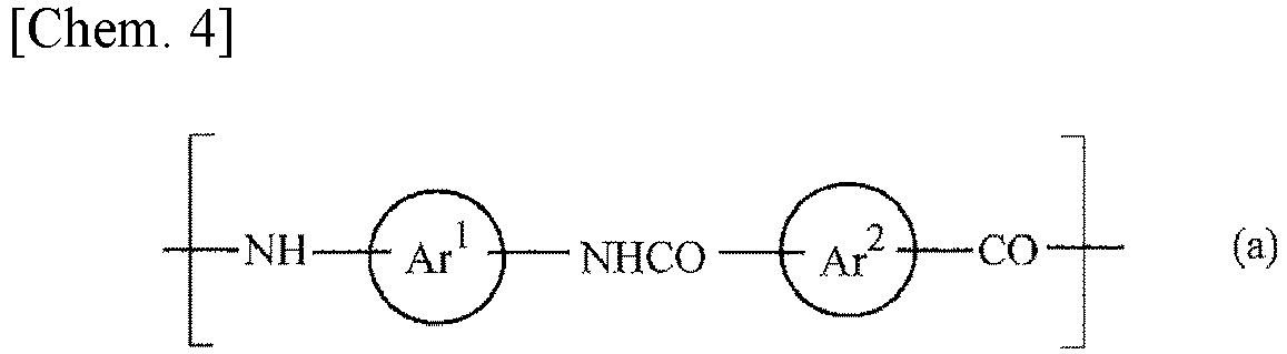
- where Ar1 and Ar2 are the same or different, and each represents an aromatic ring or a group in which two or more aromatic rings are bonded via a single bond or a linking group. Examples of the aromatic ring include aromatic hydrocarbon rings with from 6 to 10 carbon atoms, such as a benzene ring or a naphthalene ring. Examples of the linking group include a divalent hydrocarbon group (for example, a linear or branched alkylene group having from 1 to 18 carbons, and a divalent alicyclic hydrocarbon group having from 3 to 18 carbons), a carbonyl group (-CO-), an ether bond (-O-), an ester bond (-COO-), -NH-, and -SO2-. The aromatic ring can also have various substituents [such as halogen atoms, alkyl groups (e.g., C1-4 alkyl groups), oxo groups, hydroxyl groups, substituted oxy groups (e.g., C1-4 alkoxy groups and C1-4 acyloxy groups), carboxyl groups, substituted oxycarbonyl groups (e.g., C1-4 alkoxycarbonyl groups), cyano groups, nitro groups, substituted or unsubstituted amino groups (e.g., mono- or di-C1-4 alkylamino groups), and sulfo groups]. In addition, an aromatic or non-aromatic heterocyclic ring may be fused to the aromatic ring.
- The aramid fiber can be manufactured, for example, by reacting at least one of aromatic diamine to a halide of at least one of aromatic dicarboxylic acid (solution polymerization, interfacial polymerization, or the like).
- Examples of the aromatic dicarboxylic acid include isophthalic acid, terephthalic acid, 1,4-naphthalene dicarboxylic acid, 2,6-naphthalene dicarboxylic acid, 4,4'-biphenyl dicarboxylic acid, 3,3'-biphenyldicarboxylic acid, and 4,4'-diphenyletherdicarboxylic acid.
- Examples of the aromatic diamine acid include p-phenylenediamine, m-phenylenediamine, 4,4'-diaminobiphenyl, 2,4-diaminodiphenylamine, 4,4'-diaminobenzophenone, 4,4'-diaminodiphenylether, 4,4'-diaminodiphenylmethane, 4,4'-diaminodiphenylamine, 4,4'-diaminodiphenylsulfone, 2,4-diaminotoluene, 2,6-naphthalenediamine, and 1,5-naphthalenediamine.
- The aramid fiber can be manufactured by spinning the wholly aromatic polyamide into fibers using known customary methods (e.g., via spinning, washing, drying, and other processes). Furthermore, after the wholly aromatic polyamide is spun into fibers, the fibers can be, for example, shred as necessary. For example, an ultrahigh-pressure homogenizer or the like can be used to add strong mechanical shear force for microfibrillation.
- Commercially available products such as a fibrous material aramid "TIARA" (available from Daicel FineChem Ltd.) may be used as the aramid fiber.
- The lowest viscosity up to 80°C (lowest viscosity during heating to 80°C) as well as the viscosity at 25°C (viscosity at 25°C) of the slurry according to an embodiment of the present invention are complex viscosities respectively measured at a frequency of 1 Hz using an MCR rheometer at from 25°C to 80°C.
- The term "lowest viscosity up to 80°C" refers to, for example, a viscosity having the lowest value during the period of viscosity change when the slurry according to an embodiment of the present invention is being heated from 25°C to 80°C at 15°C/minute.
- Since the slurry according to an embodiment of the present invention contains the binder and the fibrous material described above, the temperature dependence of slurry viscosity is suppressed, and the ratio of the lowest viscosity during heating to 80°C to the viscosity at 25°C (lowest viscosity during heating to 80°C)/(viscosity at 25°C) is 0.12 or greater. Since the slurry according to an embodiment of the present invention has a ratio of lowest viscosity during heating to 80°C/viscosity at 25°C of 0.12 or greater, when the slurry viscosity is adjusted to one that gives a good coating property at a temperature near room temperature (for example, at 25°C) to form a thick coating film, and the coating film is subjected to heating to a high temperature drying condition (for example, 80°C) and drying immediately after its formation, the decrease in the slurry viscosity is suppressed such that the slurry can form the coating film that is resistant to collapse in shape. Therefore, an even and thick coating film can be formed efficiently. From the perspective of further lowering the temperature dependence of slurry viscosity to efficiently form an even and thick coating film, the slurry preferably has a ratio of (lowest viscosity during heating to 80°C)/(viscosity at 25°C) of 0.15 or greater, more preferably 0.2 or greater, more preferably 0. 25 or greater, more preferably 0.3 or greater, more preferably 0.4 or greater, more preferably 0.5 or greater, more preferably 0.6 or greater, more preferably 0.7 or greater, even more preferably 0.8 or greater, and particularly preferably 0.9 or greater.
- When the slurry according to an embodiment of the present invention is being heated to 80°C, the slurry viscosity typically decreases compared to the viscosity at 25°C. However, as the temperature rises, the slurry may partially gel, and the slurry viscosity may increase compared to the viscosity at 25°C. When the slurry gels at a high temperature, drying the slurry becomes difficult, and may take a long time, reducing efficiency. Therefore, from the perspective of efficient drying at a high temperature, the slurry according to an embodiment of the present invention preferably has a ratio of a highest viscosity up to 80°C (highest viscosity during heating to 80°C) to a viscosity at 25°C (viscosity at 25°C), that is, (highest viscosity during heating to 80°C)/(viscosity at 25°C), of 3.0 or smaller, more preferably 2.5 or smaller, more preferably 2.0 or smaller, more preferably 1.5 or smaller, and particularly preferably 1.0 or smaller.
- The term "highest viscosity up to 80°C" refers to, for example, a viscosity having the highest value during the period of viscosity change when the slurry according to an embodiment of the present invention is being heated from 25°C to 80°C at 15°C/minute.
- The viscosity of the slurry according to an embodiment of the present invention, at 25°C, is, for example, from 0.6 to 100 Pa·s (preferably from 0.8 to 50 Pa·s, particularly preferably from 1.0 to 30 Pa·s) from the perspective of providing excellent coatability. The viscosity of the slurry at 25°C can be adjusted to the above ranges by, for example, adding a solvent. Examples of the solvent include water; alcohols such as methanol, ethanol, propanol, and 2-propanol; cyclic ethers such as tetrahydrofuran and 1,4-dioxane; chain amides such as N,N-dimethylformamide and N,N-dimethylacetamide; cyclic amides such as N-methylpyrrolidone and N-ethylpyrrolidone; and sulfoxides such as methyl sulfoxide. Among these solvents, water is preferably used from the perspective of having small environmental load and excellent safety.
- From the perspective of easily preserving the shape of the coating film when raising the temperature to a high temperature drying condition, the lowest viscosity of the slurry according to an embodiment of the present invention during heating to 80°C is preferably, for example, from 0.25 to 90 Pa s, more preferably from 0.5 to 45 Pa s, and particularly preferably from 1 to 30 Pa·s.
- When the slurry according to an embodiment of the present invention is used to form an electrode active material layer of an electrode of a battery, the slurry preferably further contains an active material. Examples of the active material include carbon materials (carbon), elemental metals, elemental silicon (silicon), silicon compounds, mineral substances (zeolite, diatomaceous earth, fired diatomaceous earth, talc, kaolin, sericite, bentonite, smectite, clay, etc.), metal carbonates (magnesium carbonate, heavy calcium carbonate, light calcium carbonate, etc.), metal oxides [alumina, zinc oxide, manganese dioxide, titanium dioxide, lead dioxide, silver oxide, nickel oxide, and lithium-containing complex oxide (e.g., LiCoO2, lithium titanate, etc.)], metal hydroxides (aluminum hydroxide, calcium hydroxide, magnesium hydroxide, nickel hydroxide, cadmium hydroxide, etc.), and metal sulfates (calcium sulfate, barium sulfate, etc.). One of these materials may be used alone, or two or more thereof can be used in combination. Among these materials, a metal oxide, a lithium-containing complex oxide, an elemental silicon, a silicon compound, or a carbon material is preferred as the active material.
- The active material is preferably selected and used depending on the type of the cell. For a lithium-ion battery, a cathode active material is preferably a lithium-containing complex oxide (in particular, lithium cobalt oxide, lithium nickel oxide, lithium manganate, and alloys thereof), and an anode active material is preferably at least one selected from an elemental silicon, a silicon compound, a carbon material (particularly graphite), a metal oxide, and a lithium-containing complex oxide (particularly lithium titanate and niobium titanium oxides).
- Examples of the simple silicon include silicon such as amorphous silicon (amorphous silicon) and low crystalline silicon.
- Examples of the silicon compound include silicon oxide (such as SiO), metal silicates (calcium silicate, aluminum silicate, magnesium silicate, magnesium aluminosilicate, etc.), alloys of silicon and transition metals (tin, titanium, etc.), silicon composites (such as a composite of silicon and SiO), and silicon carbide.
- Examples of the carbon material include natural graphite, artificial graphite, amorphous carbon, hard carbon, graphite, mesocarbon microbeads, and pitch-based carbon fibers.
- Examples of the metal oxide used in the anode include alloys and oxides of Ti, Sn, and Co.
- The slurry according to an embodiment of the present invention may further contain one or more other components in addition to the components described above. Examples of the additional component include, for example, an electrical conductivity imparting material. Examples of the electrical conductivity imparting material include metal powder, conductive polymers, and acetylene black.
- The slurry according to an embodiment of the present invention can be manufactured by uniformly mixing the compounds described above using a generally known device for mixing, such as a rotation/revolution-type agitating and defoaming device, a homodisper, a homogenizer, a planetary mixer, a three-roll mill, or a bead mill. Here, each component may be mixed at the same time or sequentially.
- A content of the binder in the total amount of nonvolatile matter contained in the slurry according to an embodiment of the present invention is, for example, from 0.01 to 2.0 parts by weight, preferably from 0.1 to 1.5 parts by weight, particularly preferably from 0.3 to 1.0 parts by weight.
- A content of the fibrous material in the total amount of nonvolatile matter contained in the slurry according to an embodiment of the present invention is, for example, from 0.01 to 5.0 wt.%, preferably from 0.1 to 3.0 wt.%, particularly preferably from 0.3 to 1.5 wt.%.
- A total content of the fibrous material and the binder in the total amount of nonvolatile matter contained in the slurry according to an embodiment of the present invention is, for example, from 0.01 to 10.0 wt.%, preferably from 0.1 to 5.0 wt.%, particularly preferably from 0.5 to 2.0 wt.%.
- When the slurry according to an embodiment of the present invention contains a binder, a content of the fibrous material is preferably approximately from 0.5 to 5.0 times, particularly preferably from 1.0 to 3 times, most preferably from 1.0 to 2.0 times, the content of the binder.
- In the slurry according to an embodiment of the present invention, a total solid content concentration of the binder and the fibrous material is, for example, from 0.02 to 20 wt.%, preferably from 0.1 to 10 wt.%, more preferably from 0.5 to 5 wt.%. When the slurry according to an embodiment of the present invention has such a configuration, the configuration preferably facilitates the adjustment of the slurry viscosity at 25°C to impart good coating property, while suppressing the temperature dependence of the slurry viscosity.
- When the slurry according to an embodiment of the present invention contains an active material, a proportion of the active material in the total amount (100 wt.%) of nonvolatile matter contained in the slurry is, for example, 90 wt.% or greater, preferably 95 wt.% or greater, particularly preferably 99 wt.% or greater. The active material contained in this range in the slurry according to an embodiment of the present invention can increase battery capacity of the electrode prepared using the slurry according to an embodiment of the present invention.
- When the slurry according to an embodiment of the present invention contains an active material and a binder, a content of the binder in the slurry according to an embodiment of the present invention is from 0.01 to 10.0 parts by weight, preferably from 0.1 to 5.0 parts by weight, particularly preferably from 0.3 to 2.0 parts by weight, per 100 parts by weight of the active material contained in the slurry. The binder contained in the ranges described above in the slurry according to an embodiment of the present invention facilitates the improvement of the adhesion to a current collector while suppressing the decrease in battery capacity. When the content of the binder exceeds the ranges described above, the adhesion to a current collector readily improves, but the battery capacity tends to decrease. Meanwhile, when the content of the binder falls below the ranges described above, the adhesion to a current collector may become insufficient to cause the electrode active material layer to fall off from the current collector, causing the decrease in the battery capacity.
- When the slurry of the present invention contains an active material, a total solid concentration of the binder, the fibrous material, and active material is, for example, from 20 to 70 wt.%, preferably from 35 to 60 wt.%. When the slurry according to an embodiment of the present invention has such a configuration, the configuration preferably facilitates the adjustment of the slurry viscosity at 25°C to impart good coating property, while suppressing the temperature dependence of the slurry viscosity.
- When the slurry according to an embodiment of the present invention contains an active material, a content of the binder in a supernatant obtained by centrifuging (for example, 5000 rpm × 5 minutes) the slurry is 45 wt.% or greater, preferably 60 wt.% or greater, particularly preferably 80 wt.% or greater, and most preferably 95 wt.% or greater, of the total amount of binder contained in the slurry. When the slurry according to an embodiment of the present invention has such a configuration, the slurry can exhibit excellent adhesion even without an increase in the binder content, or even with a reduction in the binder content compared to the content known in the related art. Therefore, the slurry according to an embodiment of the present invention can improve adhesion without the reduction in the content proportion of the active material, or can improve adhesion with the increase in the content proportion of the active material compared to the content known in the art, and can form an electrode having both excellent adhesion and high battery capacity.
- As described above, the fibrous materials of the slurry according to an embodiment of the present invention are dispersed in the binder and are entangled with each other to form a three-dimensional network. Such a three-dimensional network structure stays preserved even when the slurry is heated to a high temperature (for example, to 80°C), inhibiting a decrease in viscosity, which means that the slurry has a reduced temperature dependence of viscosity. As such, when the slurry viscosity is adjusted to one that gives a good coating property at a temperature near room temperature (for example, at 25°C) to form a thick coating film, and the coating film is subjected to heating to a high temperature drying condition (for example, 80°C) and drying immediately after its formation, the decrease in the slurry viscosity is suppressed such that the slurry can form the coating film that is resistant to collapse in shape. Therefore, an even and thick coating film (solidified product) can be formed efficiently. When the slurry does not contain a fibrous material and only contains a binder, the temperature dependence of slurry viscosity increases, and the shape of the coating film tends to collapse, making it difficult to efficiently form an even and thick coating film (solidified product).
- The adherend, to which the slurry according to an embodiment of the present invention is applied, is not limited, and various known or commonly used substrates having a surface for coating can be used, such as a metal substrate, a plastic substrate, a ceramic substrate, a semiconductor substrate, a glass substrate, a paper substrate, and a wood substrate (wooden substrate). In particular, when the slurry according to an embodiment of the present invention contains an active material, it is preferable to form an electrode active material layer using a metal foil, which serves as a current collector, as the adherend.
- A coating thickness of the slurry according to an embodiment of the present invention is preferably 5 µm or greater, more preferably 50 µm or greater, even more preferably 100 µm or greater, and particularly preferably 200 µm or greater after drying. Since the slurry according to an embodiment of the present invention has a low temperature dependence of viscosity, the viscosity is less likely to decrease even at a high temperature, and even when the film thickness of the coating film is 100 µm or greater, the slurry can be dried and solidified efficiently to form a thick coating film (solidified product) having an even film thickness. Meanwhile, from the perspective of preserving the shape of the coating film at a high temperature, a thickness of the coating film after drying is preferably, for example, 500 µm or less.
- Examples of the method of applying the slurry include screen printing methods, mask printing methods, offset printing methods, inkjet printing methods, flexographic printing methods, gravure printing methods, stamping, dispensing, squeegee printing methods, silk screen printing methods, spraying and brushing. Furthermore, a film applicator, a bar coater, a die coater, a comma coater, a gravure coater, a blade coater, and the like can be used for applying the slurry.
- Since the slurry according to an embodiment of the present invention has a low temperature dependence of viscosity, the shape of the coating film can be preserved even when the coating film is being heated to a high temperature and dried immediately after application. Therefore, the coating film can be efficiently dried and solidified in a short time. The method of drying the applied slurry is not particularly limited, and examples thereof include drying methods through heating, pressure reduction, blowing, and the like. From the perspective of efficient drying and solidification, the drying temperature is preferably from 70°C to 150°C, more preferably from 80 to 120°C. The drying time is, for example, from 1 minute to 5 hours, preferably from 10 minutes to 1 hour, under the drying temperature condition described above. In addition, the degree and time of pressure reduction, the amount of gas to be blown, the blowing rate, the blowing temperature, the type of gas to be blown, the degree of drying, the area to be blown, the direction of the gas to be blown, and the like can be selected arbitrarily.
- When the slurry according to an embodiment of the present invention contains an active material, the slurry can be suitably used to form an electrode active material layer for a battery. Furthermore, when the slurry according to an embodiment of the present invention is used, an electrode having a high battery capacity can be formed efficiently.
- In addition to the use in an electrode of a battery, the slurry according to an embodiment of the present invention can also be suitably used in various applications involving application, drying, and solidification on an adherend, such as paints, foods, and drug additives.
- The electrode according to an embodiment of present invention contains a laminate of an electrode active material layer and a current collector, the electrode active material layer including a solidified product of the slurry described above which contains an active material. The electrode according to an embodiment of the present invention may contain components other than the solidified product of the slurry and the current collector.
- The electrode according to an embodiment of the present invention can be manufactured by, for example, applying the slurry to at least one surface of the current collector and drying the slurry to solidify the slurry.
- The current collector includes a positive electrode current collector and a negative electrode current collector, and the positive electrode current collector is formed of, for example, an aluminum foil. In addition, the negative electrode current collector is formed of, for example, a copper foil.
- The amount of slurry applied to the current collector, the thickness after drying, the coating method, the drying and solidification conditions, and the like are the same as those described above regarding the adherend.
- Since the slurry according to an embodiment of present invention has a low temperature dependence of viscosity, even when the coating film is heated to a high temperature for drying and solidification, an electrode active material layer can be formed, wherein the electrode active material layer has a small difference between a film thickness at an edge of the electrode active material layer (edge film thickness) to a film thickness at a center of the electrode active material layer (center film thickness). That is, the ratio of a film thickness at an edge of the electrode active material layer to a film thickness at a center of the electrode active material layer, (edge film thickness)/(center film thickness), is preferably 0.9 or greater, more preferably 0.95 or greater, and even more preferably 0.98 or greater. When the ratio of (edge film thickness)/(center film thickness) of the electrode active material layer is set to 0.9 or greater, the density of the active material in the electrode active material layer are made even, and an electrode having high capacity and high quality can be obtained.
- The ratio of a film thickness at an edge of the electrode active material layer to a film thickness at a center of the electrode active material layer, (edge film thickness)/(center film thickness), of the electrode active material layer described above can be measured by the following method.
- The slurry according to an embodiment of the present invention is evenly applied to one side of a square copper foil having a thickness of 15 µm and a length of 150 mm such that the thickness of the resulting coating film after drying is 50 µm or greater. Thereafter, with the coating film facing upward, the copper foil is heated to 80°C and subjected to drying and solidification for one hour to form an electrode active material layer. The smallest film thickness at an edge of the formed electrode active material layer is defined as the edge film thickness, while the largest film thickness at a center of the formed electrode active material layer is defined as the center film thickness. Based on these values, the ratio of a film thickness at an edge of the electrode active material layer to a film thickness at a center of the electrode active material layer, (edge film thickness)/(center film thickness), is calculated. The edge film thickness and the center film thickness of the electrode active material layer can be measured by, for example, a micrometer (available from Mitutoyo Corporation).
- The electrode of the present invention has particularly excellent adhesion between the electrode active material layer including the solidified product of the slurry described above and the current collector, and has a peel strength of, for example, 2.0 N/m or greater, preferably 3.0 N/m or greater, particularly preferably 3.5 N/m or greater. The upper limit of the peel strength is, for example, 70.0 N/m. Therefore, even when the electrode expands and contracts due to repeated charging and discharging, the electrode active material layer can be prevented from peeling off the current collector, and the cell capacity can be stably maintained over a long period of time.
- In addition, the electrode according to an embodiment of the present invention contains the electrode active material layer containing the solidified product of the slurry described above, and can efficiently form an electrode active material layer having a large film thickness (for example, an electrode active material layer having a film thickness of 50 µm or greater, preferably 80 µm or greater, and even more preferably 100 µm or greater). Therefore, the use of the electrode according to an embodiment of the present invention facilitates efficient production of a battery having a high capacity.
- The cell according to an embodiment of the present invention is provided with the electrode described above. The cell of the present invention may be a wound cell formed by laminating electrodes (positive electrode and a negative electrode) and a separator, winding the laminate, and enclosing the laminate in a container such as a can together with an electrolyte solution, or a laminated cell in which a sheet-shaped product formed by laminating electrodes (positive electrode and a negative electrode) and a separator is encapsulated in a relatively flexible sheath body together with an electrolyte solution.
- Examples of the cell according to an embodiment of the present invention include secondary cells such as lithium ion cells, nickel/hydrogen rechargeable cells, and nickel/cadmium cells; primary cells such as manganese dry cells, alkaline manganese cells, and lithium primary cells; and electric double-layer capacitors.
- In the battery according to an embodiment of the present invention, an electrode active material layer having a large film thickness (for example, an electrode active material layer having a film thickness of 50 µm or greater) can be efficiently formed on a current collector, making it possible to efficiently increase the battery capacity. Therefore, the cell according to an embodiment of the present invention can suitably be used in information-related devices such as smartphones and notebook computers, hybrid vehicles, electric vehicles, and the like.
- Hereinafter, the present invention will be described more specifically with reference to examples, but the present invention is not limited by these examples.
- Commercially available hardwood pulp was suspended in water, and 100 L of a 1 wt.% slurry solution (1) was obtained.
- Next, the obtained slurry solution was beaten ten times to be refined, with a clearance of 0.15 mm and at a disk rotation speed of 1750 rpm, using a disc refiner (trade name "SUPERFIBRATER400-TFS" available from Hasegawa Refrigeration, Ltd.).
- The 1% by weight slurry solution after the refiner treatment was further homogenized 50 times, at a processing pressure of 50 MPa, using a homogenizer (available from Gaulin Corporation, trade name "15M8AT").
- The 1% by weight slurry solution after the refiner treatment and the homogenization treatment was repeatedly filtered through gauze to yield a slurry solution having a nonvolatile matter concentration of 9.9% by weight.
- Water was added to the obtained 9.9 wt.% slurry solution, and the mixture was stirred using a homodisper (available from Tokushu Kika Kogyo Co., Ltd., Model L) for 5 minutes at 3000 rpm to yield a 1.2 wt.% slurry solution. The obtained 1.2 wt.% slurry solution was CNF slurry solution (1).
- Ten strands of fibers contained in the obtained CNF slurry solution (1) were randomly selected, and the lengths and diameters of the selected fibers were measured by observing the fibers using an electron microscope (SEM or TEM). As a result, an average thickness of the 10 fibers was 79.2 nm, an average length thereof was 6.14 µm, and an average aspect ratio (average length/average thickness) thereof was 78.
- 3 g of commercially available softwood bleached kraft pulp fiber was thoroughly stirred in 297 g of ion exchanged water. Then, 1.25 wt.% of TEMPO (2,2,6,6-tetramethylpiperidine-1-oxyl radical, ALDRICH, Free radical, 98%), 12.5 wt.% of sodium bromide (FUJIFILM Wako Pure Chemical Corporation), 56.8 wt.% of sodium hypochlorite (FUJIFILM Wako Pure Chemical Corporation, Ltd., Cl: 5%) were added, in this order, per 3 g of the pulp. Using a pH stat, the pH of the mixture was maintained at 10.5 by adding a 0.5 M sodium hydroxide dropwise, and an oxidation reaction was carried out at a temperature of 20°C. The dropwise addition was then stopped at an oxidation time of 120 minutes to obtain an oxidized pulp. The oxidized pulp was thoroughly washed with ion exchanged water, subjected to a dehydration treatment, and dried naturally in an atmosphere of 20°C. Thereafter, 1.2 g of the oxidized pulp and 98.8 g of ion exchanged water were stirred at 3000 rpm for 10 minutes using a homodisper (available from Tokushu Kika Kogyo Co., Ltd., Model L) to refine the fibers, resulting in a slurry solution. The solid content concentration of the oxidized pulp in the obtained slurry solution was 1.2 wt.%. The obtained 1.2 wt.% slurry solution was CNF slurry solution (2).
- Ten strands of fibers contained in the obtained CNF slurry solution (2) were randomly selected, and the lengths and diameters of the selected fibers were measured by observing the fibers using an electron microscope (SEM or TEM). As a result, an average thickness of the ten strands of fibers was 3.1 nm, an average length thereof was 1.00 µm, and an average aspect ratio (average length/average thickness) thereof was 323.
- 84 g of the CNF slurry solution (1) obtained in Preparation Example 1 was charged in a polypropylene container, and 67.5 g of a 1.5 wt.% CMC aqueous solution (CMC: carboxymethylcellulose sodium salt; viscosity of a 1 wt.% aqueous solution at 25°C and 60 rotations: 1500 to 3000 mPa·s; available from Daicel FineChem Ltd., Product No. 2200) was added. Then, 99.0 g of artificial graphite (average particle size: approximately 20 µm) was added as an active material. The solution mixture was stirred for 30 minute at 3000 rpm using a homodisper (available from Tokushu Kika Kogyo Co., Ltd., Model L), resulting in slurry (1).
- Regarding the viscosity of the obtained slurry (1), the complex viscosity at 25°C (viscosity at 25°C) and the lowest complex viscosity during heating from 25°C to 80°C at 15°C/minute (lowest viscosity during heating to 80°C) were measured using an MCR rheometer at a frequency of 1 Hz. The viscosity at 25°C, the lowest viscosity during heating to 80°C, and the ratio of (lowest viscosity during heating to 80°C)/(viscosity at 25°C) are shown in Table 1.
- A slurry (2) was obtained in the same manner as in Example 1 with the exception that the CNF slurry solution (2) obtained in Preparation Example 2 was used instead of the slurry (1), and the viscosity at 25°C and the lowest viscosity during heating to 80°C of slurry (2) were measured. The viscosity at 25°C, the lowest viscosity during heating to 80°C, and the ratio of (lowest viscosity during heating to 80°C)/(viscosity at 25°C) are shown in Table 1.
- A slurry (3) was obtained in the same manner as in Example 1 with the exception that cellulose nanocrystals (CelluForce NCC, available from CelluForce, 1.2 wt.% aqueous slurry solution, average thickness: 7.1 nm, average length: 0.15 µm, average aspect ratio or average length/average thickness: 21) were used instead of the slurry (1), and the viscosity at 25°C and the lowest viscosity during heating to 80°C of slurry (3) were measured. The viscosity at 25°C, the lowest viscosity during heating to 80°C, and the ratio of (lowest viscosity during heating to 80°C)/(viscosity at 25°C) are shown in Table 1.
- A slurry was prepared in the same manner as in Example 1 with the exception that 2 g of an SBR water dispersion (product name TRD 2001, available from JSR) instead of the slurry (1) was used to adjust the water content so that the solid content concentration became 40%, and the viscosity at 25°C and the lowest viscosity during heating to 80°C of the slurry of Comparative Example 1 were measured. The viscosity at 25°C, the lowest viscosity during heating to 80°C, and the ratio of (lowest viscosity during heating to 80°C)/(viscosity at 25°C) are shown in Table 1.
[Table 1] Viscosity at 25°C (Pa•s) Lowest viscosity during heating to 80°C (Pa•s) (Lowest viscosity during heating to 80°C)/(viscosity at 25°C) Example 1 9.472 8.603 0.908 Example 2 8.074 6.164 0.763 Example 3 2.750 1.201 0.437 Comparative Example 1 2.076 0.241 0.116 - A slurry (4) was obtained in the same manner as in Example 1 with the exception that artificial graphite was not added as an active material, and the viscosity at 25°C and the lowest viscosity during heating to 80°C of slurry (4) were measured. The viscosity at 25°C was 3.678 Pa·s, the lowest viscosity during heating to 80°C was 0.700 Pa·s, and the ratio of (lowest viscosity during heating to 80°C)/(viscosity at 25°C) was 0.190.
- A slurry was obtained in the same manner as in Comparative Example 1 with the exception that artificial graphite was not added as an active material, and the viscosity at 25°C and the lowest viscosity during heating to 80°C of the slurry of Comparative Example 2 were measured. The viscosity at 25°C was 0.883 Pa·s, the lowest viscosity during heating to 80°C was 0.049 Pa·s, and the ratio of (lowest viscosity during heating to 80°C)/(viscosity at 25°C) was 0.055.
- Each of the slurries (1) to (3) obtained in Examples 1 to 3 and the slurry obtained in Comparative Example 1 was applied on a square copper foil having a thickness of 15 µm and a length of 150 mm using an applicator such that the thicknesses of the resulting coating films after drying were 50 µm or greater. Thereafter, with the coating films facing upward, the copper foils were heated to 80°C at 15°C/minute and subjected to drying and solidification for one hour to produce electrodes having an electrode active material layer formed on one side of the copper foil. The film thicknesses of the electrode active material layers of the obtained electrodes were measured using a micrometer (available from Mitutoyo Corporation). The smallest film thickness at an edge of an electrode active material layer was defined as the edge film thickness, while the largest film thickness at a center of an electrode active material layer was defined as the center film thickness. Based on the values, the ratios of the film thickness at an edge of an electrode active material layer to the film thickness at a center of an electrode active material layer, (edge film thickness)/(center film thickness), were calculated. The results are shown in Table 2.
[Table 2] Edge film thickness (µm) Center film thickness (µm) (Edge film thickness)/(center film thickness) Example 1 114 120 0.95 Example 2 110 121 0.91 Example 3 105 117 0.90 Comparative Example 1 96 115 0.83 - Variations of embodiments of the present invention described above are additionally described below.
- [1] A slurry containing at least a binder and a fibrous material, the slurry having a ratio of a lowest viscosity up to 80°C (lowest viscosity during heating to 80°C) to a viscosity at 25°C (viscosity at 25°C), (lowest viscosity during heating to 80°C)/(viscosity at 25°C), of 0.12 or greater (preferably 0.15 or greater, more preferably 0.2 or greater, more preferably 0. 25 or greater, more preferably 0.3 or greater, more preferably 0.4 or greater, more preferably 0.5 or greater, more preferably 0.6 or greater, more preferably 0.7 or greater, even more preferably 0.8 or greater, and particularly preferably 0.9 or greater).
- [2] The slurry according to [1], wherein a ratio of a highest viscosity up to 80°C (highest viscosity during heating to 80°C) to the viscosity at 25°C (viscosity at 25°C), (highest viscosity during heating to 80°C)/(viscosity at 25°C), is 3.0 or smaller (preferably 2.5 or smaller, more preferably 2.0 or smaller, more preferably 1.5 or smaller, and particularly preferably 1.0 or smaller).
- [3] The slurry according to [1] or [2], wherein the viscosity at 25°C is from 0.6 to 100 Pa s (preferably from 0.8 to 50 Pa·s, more preferably from 1.0 to 30 Pa·s).
- [4] The slurry according to any one of [1] to [3], wherein the lowest viscosity during heating to 80°C is from 0.25 to 90 Pa·s (preferably from 0.5 to 45 Pa·s, more preferably from 1 to 30 Pa·s).
- [5] The slurry according to any one of [1] to [4], wherein the binder is an aqueous binder having a solubility in water at 20°C of 1 g/L or greater, or an aqueous binder dispersed in water at 20°C with a particle size of 1 µm or smaller (particle size measurement method: laser diffraction method).
- [6] The slurry according to any one of [1] to [5], wherein the binder has a melting point (or decomposition temperature in case of the binder having no melting point) of 160°C or higher (preferably 180°C or higher, more preferably 200°C or higher; the upper limit is preferably 400°C).
- [7] The slurry according to any one of [1] to [6], wherein a viscosity of a 1 wt.% aqueous solution of the binder (at 25°C and 60 rotations) is from 10 to 5000 mPa·s (preferably from 50 to 3000 mPa·s, more preferably from 100 to 2000 mPa·s).
- [8] The slurry according to any one of [1] to [7], wherein the binder is at least one selected from the group consisting of a polysaccharide derivative (1), a compound having a constituent unit represented by Formula (2) above, and a compound having a constituent unit represented by Formula (3) above [preferably a polysaccharide derivative (1)].
- [9] The slurry according to [8], wherein the polysaccharide derivative (1) is a cellulose or a derivative of a cellulose (preferably a compound having a constituent unit represented by Formula (1-1) above).
- [10] The slurry according to [9], wherein the cellulose or the derivative of a cellulose is at least one selected from the group consisting of hydroxyethyl cellulose, hydroxypropyl cellulose, carboxymethyl cellulose, and alkali salts thereof (for example, sodium carboxymethylcellulose and ammonium carboxymethylcellulose).
- [11] The slurry according to any one of [1] to [10], wherein the fibrous material is at least one selected from the group consisting of a cellulose fiber, an aramid fiber, a polyphenylene sulfide fiber, a polyimide fiber, a fluorine fiber, a glass fiber, a carbon fiber, a poly-p-phenylene benzoxazole fiber, a polyether ether ketone fiber, a liquid crystal polymer fiber, a metal, a semiconductor, a carbon material, and an electrically conductive polymer (preferably a cellulose fiber and/or an aramid fiber, more preferably a cellulose fiber).
- [12] The slurry according to any one of [1] to [11], wherein an average thickness (average diameter D) of the fibrous material is from 1 to 1000 nm (preferably from 3 to 500 nm, more preferably from 3 to 200 nm).
- [13] The slurry according to any one of [1] to [12], wherein an average length (average length L) of the fibrous material is from 0.01 to 1000 µm (preferably from 0.3 to 200 µm, more preferably from 0.5 to 100 µm, even more preferably from 1 to 20 µm).
- [14] The slurry according to any one of [1] to [13], wherein an average aspect ratio, (average length/average thickness), of the fibrous material is from 10 to 1000 (preferably from 15 to 500, more preferably from 20 to 100).
- [15] The slurry according to any one of [1] to [14], wherein a content of the binder in the total amount of nonvolatile matter contained in the slurry is from 0.01 to 2.0 parts by weight (preferably from 0.1 to 1.5 parts by weight, and more preferably from 0.3 to 1.0 parts by weight).
- [16] The slurry according to any one of [1] to [15], wherein a total content of the fibrous material and the binder in the total amount of nonvolatile matter contained in the slurry is from 0.01 to 10.0 wt.% (preferably from 0.1 to 5.0 wt.%, particularly preferably from 0.5 to 2.0 wt.%).
- [17] The slurry according to any one of [1] to [16], wherein a content of the fibrous material is from 0.5 to 5.0 times (preferably from 1.0 to 3 times, more preferably from 1.0 to 2.0 times) the content of the binder.
- [18] The slurry according to any one of [1] to [17], wherein a total solid content concentration of the binder and the fibrous material is from 0.02 to 20 wt.% (preferably from 0.1 to 10 wt.%, more preferably from 0.5 to 5 wt.%).
- [19] A solidified product of the slurry described in any one of [1] to [18].
- [20] The slurry according to any one of [1] to [18], wherein the slurry further contains an active material.
- [21] The slurry according to [20], wherein the active material is at least one selected from the group consisting of a metal oxide, a lithium-containing complex oxide, a simple silicon, a silicon compound, and a carbon material.
- [22] The slurry according to [20] or [21], wherein a proportion of the active material in the total amount (100 wt.%) of nonvolatile matter contained in the slurry is 90 wt.% or greater (preferably 95 wt.% or greater, more preferably 99 wt.% or greater).
- [23] The slurry according to any one of [20] to [22], wherein a content of the binder is from 0.01 to 10.0 parts by weight (preferably from 0.1 to 5.0 parts by weight, more preferably from 0.3 to 2.0 parts by weight) per 100 parts by weight of the active material.
- [24] The slurry according to any one of [20] to [23], wherein a total solid content concentration of the binder, the fibrous material, and the active material is from 20 to 70 wt.% (preferably from 35 to 60 wt.%).
- [25] The slurry according to any one of [20] to [24], wherein a content of the binder in a supernatant obtained by centrifuging (for example, 5000 rpm × 5 minutes) the slurry is 45 wt.% or greater (preferably 60 wt.% or greater, more preferably 80 wt.% or greater, and even more preferably 95 wt.% or greater) of the total amount of the binder contained in the slurry.
- [26] A solidified product of the slurry described in any one of [20] to [25].
- [27] An electrode including a laminate of an electrode active material layer and a current collector, wherein the electrode active material layer includes the solidified product described in [26].
- [28] The electrode according to [27], wherein a ratio of a film thickness at an edge of the electrode active material layer (edge film thickness) to a film thickness at a center of the electrode active material layer (center film thickness), (edge film thickness)/(center film thickness), is 0.9 or greater (preferably 0.95 or greater, more preferably 0.98 or greater).
- [29] The electrode according to [27], wherein the electrode active material layer has a film thickness of 50 µm or greater (preferably 80 µm or greater, more preferably 100 µm or greater).
- [30] A battery provided with the electrode described in any one of [27] to [30].
- The slurry according to an embodiment of the present invention can be suitably used in various applications involving application, drying, and solidification on an adherend, such as paints, foods, and drug additives. When the slurry according to an embodiment of the present invention contains an active material, the slurry can be suitably used to form an electrode active material layer for a battery. The battery according to an embodiment of the present invention can be suitably used in an information device such as a smart phone or a notebook computer, or, a hybrid vehicle or an electric vehicle.
Claims (11)
- A slurry comprising at least a binder and a fibrous material, wherein a ratio of a lowest viscosity up to 80°C (lowest viscosity during heating to 80°C) to a viscosity at 25°C (viscosity at 25°C), (lowest viscosity during heating to 80°C)/(viscosity at 25°C), is 0.12 or greater.
- The slurry according to claim 1, wherein a total solid content concentration of the binder and the fibrous material is from 0.02 to 20 wt.%.
- The slurry according to claim 1 or 2, wherein the fibrous material is a cellulose fiber.
- The slurry according to any one of claims 1 to 3, wherein the fibrous material has an average thickness from 1 to 1000 nm and an average aspect ratio from 10 to 1000.
- A solidified product of the slurry described in any one of claims 1 to 4.
- The slurry according to any one of claims 1 to 4, wherein the slurry further comprises an active material.
- The slurry according to claim 6, wherein a total solid content concentration of the binder, the fibrous material, and the active material is from 20 to 70 wt.%.
- A solidified product of the slurry according to claim 6 or 7.
- An electrode comprising a laminate of an electrode active material layer and a current collector, the electrode active material layer including the solidified product described in claim 8.
- The electrode according to claim 9, wherein a ratio of a film thickness at an edge of the electrode active material layer (edge film thickness) to a film thickness at a center of the electrode active material layer (center film thickness), (edge film thickness)/(center film thickness), is 0.9 or greater.
- A battery comprising the electrode described in claim 9 or 10.
Applications Claiming Priority (1)
| Application Number | Priority Date | Filing Date | Title |
|---|---|---|---|
| PCT/JP2019/011236 WO2020188707A1 (en) | 2019-03-18 | 2019-03-18 | Slurry |
Publications (2)
| Publication Number | Publication Date |
|---|---|
| EP3944364A1 true EP3944364A1 (en) | 2022-01-26 |
| EP3944364A4 EP3944364A4 (en) | 2023-03-08 |
Family
ID=72519282
Family Applications (1)
| Application Number | Title | Priority Date | Filing Date |
|---|---|---|---|
| EP19920090.8A Pending EP3944364A4 (en) | 2019-03-18 | 2019-03-18 | Slurry |
Country Status (7)
| Country | Link |
|---|---|
| US (1) | US20220158190A1 (en) |
| EP (1) | EP3944364A4 (en) |
| JP (1) | JP7261864B2 (en) |
| KR (1) | KR102763956B1 (en) |
| CN (1) | CN113228338A (en) |
| TW (1) | TWI844640B (en) |
| WO (1) | WO2020188707A1 (en) |
Cited By (1)
| Publication number | Priority date | Publication date | Assignee | Title |
|---|---|---|---|---|
| CN116565107A (en) * | 2022-01-27 | 2023-08-08 | 宁德时代新能源科技股份有限公司 | Negative electrode sheet, secondary battery, battery module, battery pack and electrical device |
Families Citing this family (2)
| Publication number | Priority date | Publication date | Assignee | Title |
|---|---|---|---|---|
| KR20220059744A (en) | 2020-11-03 | 2022-05-10 | 주식회사 엘지에너지솔루션 | Shim for die coater, die coater including the same, and lithium secondary battery including a positive electrode manufactured using the same |
| CN121054629B (en) * | 2025-11-03 | 2026-05-08 | 广东工业大学 | A thick electrode, its preparation method and application |
Family Cites Families (13)
| Publication number | Priority date | Publication date | Assignee | Title |
|---|---|---|---|---|
| JP3687736B2 (en) * | 2000-02-25 | 2005-08-24 | 日本電気株式会社 | Secondary battery |
| JP3979534B2 (en) | 2001-07-02 | 2007-09-19 | アクゾ ノーベル エヌ.ブイ. | Pigment composition |
| TWI228553B (en) | 2001-11-16 | 2005-03-01 | Du Pont | Method of producing coating compositions and coating compositions made therefrom |
| JP2009043641A (en) | 2007-08-10 | 2009-02-26 | Sanyo Electric Co Ltd | Nonaqueous electrolyte battery and negative electrode used for the same |
| CN103081185B (en) * | 2010-08-25 | 2016-04-27 | 丰田自动车株式会社 | The manufacture method of electrode for cell |
| EP2760070B1 (en) * | 2011-09-20 | 2018-05-02 | Nissan Chemical Industries, Ltd. | Slurry composition for use in forming lithium-ion secondary battery electrode, containing cellulose fiber as binder, and lithium-ion secondary battery electrode |
| JP2014154363A (en) | 2013-02-08 | 2014-08-25 | Toyota Motor Corp | Nonaqueous electrolyte secondary battery, manufacturing method of positive electrode plate of nonaqueous electrolyte secondary battery, and manufacturing method of nonaqueous electrolyte secondary battery |
| JP6268811B2 (en) | 2013-08-23 | 2018-01-31 | 日本ゼオン株式会社 | Porous film composition for lithium ion secondary battery, separator with protective layer for lithium ion secondary battery, electrode with protective layer for lithium ion secondary battery, lithium ion secondary battery, and separator with protective layer for lithium ion secondary battery Manufacturing method |
| WO2017111103A1 (en) * | 2015-12-25 | 2017-06-29 | レンゴー株式会社 | Cellulose xanthate nanofibers |
| JP6841668B2 (en) | 2016-01-19 | 2021-03-10 | 株式会社ダイセル | Binders, electrode slurries, electrodes and their manufacturing methods, and secondary batteries |
| KR102141964B1 (en) * | 2016-03-29 | 2020-08-06 | 주식회사 엘지화학 | Negative electrode active material slurry, negative electrode comprising thereof and lithium secondary battery containing the negative electrode |
| CN110192296B (en) * | 2017-01-17 | 2023-08-01 | 株式会社大赛璐 | Electrode paste, electrode, method for producing same, and secondary battery |
| US10464846B2 (en) * | 2017-08-17 | 2019-11-05 | Usg Interiors, Llc | Method for production of acoustical panels |
-
2019
- 2019-03-18 KR KR1020217021899A patent/KR102763956B1/en active Active
- 2019-03-18 CN CN201980083254.5A patent/CN113228338A/en active Pending
- 2019-03-18 US US17/440,549 patent/US20220158190A1/en not_active Abandoned
- 2019-03-18 WO PCT/JP2019/011236 patent/WO2020188707A1/en not_active Ceased
- 2019-03-18 EP EP19920090.8A patent/EP3944364A4/en active Pending
- 2019-03-18 JP JP2021506856A patent/JP7261864B2/en active Active
-
2020
- 2020-03-12 TW TW109108112A patent/TWI844640B/en active
Cited By (2)
| Publication number | Priority date | Publication date | Assignee | Title |
|---|---|---|---|---|
| CN116565107A (en) * | 2022-01-27 | 2023-08-08 | 宁德时代新能源科技股份有限公司 | Negative electrode sheet, secondary battery, battery module, battery pack and electrical device |
| EP4293755A4 (en) * | 2022-01-27 | 2025-05-21 | Contemporary Amperex Technology (Hong Kong) Limited | NEGATIVE ELECTRODE SHEET, SECONDARY BATTERY, BATTERY MODULE, BATTERY AND ELECTRICAL DEVICE |
Also Published As
| Publication number | Publication date |
|---|---|
| EP3944364A4 (en) | 2023-03-08 |
| US20220158190A1 (en) | 2022-05-19 |
| JPWO2020188707A1 (en) | 2020-09-24 |
| KR20210139214A (en) | 2021-11-22 |
| KR102763956B1 (en) | 2025-02-07 |
| CN113228338A (en) | 2021-08-06 |
| JP7261864B2 (en) | 2023-04-20 |
| TWI844640B (en) | 2024-06-11 |
| WO2020188707A1 (en) | 2020-09-24 |
| TW202046538A (en) | 2020-12-16 |
Similar Documents
| Publication | Publication Date | Title |
|---|---|---|
| US11949104B2 (en) | Slurry for forming electrode-active-material layer for cell | |
| TWI451616B (en) | Water-based carbon filler, a conductive coating material, an electrode plate for a power storage device, a method for manufacturing an electrode plate for a power storage device, a power storage device, and a current collector | |
| EP3573150B1 (en) | Electrode slurry, electrode, manufacturing method thereof, and secondary battery | |
| JP7271660B2 (en) | slurry | |
| JP2016126998A (en) | Lithium ion secondary battery separator and method for manufacturing the same | |
| TWI772337B (en) | Nonaqueous electrolyte secondary battery negative electrode and nonaqueous electrolyte secondary battery | |
| EP4144772B1 (en) | Binder composition for power storage device, slurry for power storage device electrode, power storage device electrode, and power storage device | |
| JP2015125920A (en) | Thickening/stabilizing agent for electrode coating liquid of electricity storage device, coating liquid prepared using the thickening/stabilizing agent, electrode manufactured using the coating liquid, and electricity storage device using the electrode | |
| TWI844640B (en) | Pulp | |
| JP2010093027A (en) | Electrode member-collector electrode member laminate | |
| JP2010238808A (en) | Capacitor separator electrode integrated element and capacitor using the same | |
| EP2919306B1 (en) | Nonaqueous electrolyte secondary battery and method for producing same | |
| JP7337616B2 (en) | Binder for non-aqueous electrolyte secondary battery, electrode composition for non-aqueous electrolyte secondary battery, electrode for non-aqueous electrolyte secondary battery, and non-aqueous electrolyte secondary battery | |
| CN114514631A (en) | Binder for nonaqueous electrolyte secondary battery, electrode composition for nonaqueous electrolyte secondary battery, electrode for nonaqueous electrolyte secondary battery, and method for producing binder for nonaqueous electrolyte secondary battery | |
| JPWO2020129897A1 (en) | Electrodes for non-aqueous electrolyte secondary batteries, their manufacturing methods, and non-aqueous electrolyte secondary batteries | |
| CN118919657A (en) | Manufacturing method of silicon-based composite negative plate and battery |
Legal Events
| Date | Code | Title | Description |
|---|---|---|---|
| STAA | Information on the status of an ep patent application or granted ep patent |
Free format text: STATUS: THE INTERNATIONAL PUBLICATION HAS BEEN MADE |
|
| PUAI | Public reference made under article 153(3) epc to a published international application that has entered the european phase |
Free format text: ORIGINAL CODE: 0009012 |
|
| STAA | Information on the status of an ep patent application or granted ep patent |
Free format text: STATUS: REQUEST FOR EXAMINATION WAS MADE |
|
| 17P | Request for examination filed |
Effective date: 20211014 |
|
| AK | Designated contracting states |
Kind code of ref document: A1 Designated state(s): AL AT BE BG CH CY CZ DE DK EE ES FI FR GB GR HR HU IE IS IT LI LT LU LV MC MK MT NL NO PL PT RO RS SE SI SK SM TR |
|
| DAV | Request for validation of the european patent (deleted) | ||
| DAX | Request for extension of the european patent (deleted) | ||
| A4 | Supplementary search report drawn up and despatched |
Effective date: 20230208 |
|
| RIC1 | Information provided on ipc code assigned before grant |
Ipc: H01M 4/62 20060101ALI20230202BHEP Ipc: B32B 23/04 20060101ALI20230202BHEP Ipc: H01M 4/13 20100101AFI20230202BHEP |