EP3944061A1 - Electromagnetic stylus - Google Patents
Electromagnetic stylus Download PDFInfo
- Publication number
- EP3944061A1 EP3944061A1 EP21187471.4A EP21187471A EP3944061A1 EP 3944061 A1 EP3944061 A1 EP 3944061A1 EP 21187471 A EP21187471 A EP 21187471A EP 3944061 A1 EP3944061 A1 EP 3944061A1
- Authority
- EP
- European Patent Office
- Prior art keywords
- regulating member
- refill
- electromagnetic stylus
- force sensing
- sensing component
- Prior art date
- Legal status (The legal status is an assumption and is not a legal conclusion. Google has not performed a legal analysis and makes no representation as to the accuracy of the status listed.)
- Granted
Links
Images



Classifications
-
- G—PHYSICS
- G06—COMPUTING OR CALCULATING; COUNTING
- G06F—ELECTRIC DIGITAL DATA PROCESSING
- G06F3/00—Input arrangements for transferring data to be processed into a form capable of being handled by the computer; Output arrangements for transferring data from processing unit to output unit, e.g. interface arrangements
- G06F3/01—Input arrangements or combined input and output arrangements for interaction between user and computer
- G06F3/03—Arrangements for converting the position or the displacement of a member into a coded form
- G06F3/033—Pointing devices displaced or positioned by the user, e.g. mice, trackballs, pens or joysticks; Accessories therefor
- G06F3/0354—Pointing devices displaced or positioned by the user, e.g. mice, trackballs, pens or joysticks; Accessories therefor with detection of two-dimensional [2D] relative movements between the device, or an operating part thereof, and a plane or surface, e.g. 2D mice, trackballs, pens or pucks
- G06F3/03545—Pens or stylus
Definitions
- the present disclosure relates to computer peripheral technical field, and in particular to a digital electromagnetic stylus.
- Electromagnetic styluses as digital electronic information devices are widely used, and the styluses can not only input characters by handwriting, but also realize drawing, point control operation and so on.
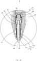
- FIG. 1 is an overall structural sectional view of an electromagnetic stylus according to a first embodiment of the present disclosure
- FIG. 2 is an enlarged schematic view of area II of the electromagnetic stylus shown in FIG. 1
- FIG. 3 is an structure decomposition view of the electromagnetic stylus of FIG. 1 ,.
- the electromagnetic stylus 100 comprises a housing 10, a refill 20, and an electromagnetic inductor 30 arranged in the housing 10.
- the housing 10 comprises an upper housing 11 and a lower housing 12 that are in cooperation with each other, a silica gel jacket 13 sleeved on the lower housing 12, and a key 14 arranged on a surface of the lower housing 12.
- the electromagnetic inductor 30 is configured to fix the refill 20 and sense a writing trajectory of the refill 20.
- the electromagnetic inductor 30 comprises a magnetic core component 31, a first regulating member 31, a second regulating member 32, a force sensing component 34, an ejector rod 35, and a resonator circuit board 36.
- the force sensing component 34 is proximal to an end portion of the refill 20, the refill 20 runs through the first regulating member 32, and the second regulating member 33 and the first regulating member 32 are adjustable relative to each other.
- the magnetic core component 31 comprises a magnetic core 311, a coil 312 wound on the magnetic core 311, and an O-ring 313 sleeved on an end, proximal to the refill 20, of the magnetic core 311.
- the magnetic core 311 is a hollow magnetic core which allows the refill 20 to run through.
- the O-ring 313 is made of silicone material, and is preferably a silica ring. The refill 20 sequentially runs through the O-ring 313 and the magnetic core 311.
- the O-ring 313 is configured to protect the magnetic core 311 and to achieve an anti-shock effect.
- FIG. 4 is a schematic perspective view of the first regulating member display in FIG. 3
- FIG. 5 is a schematic sectional view of the first regulating member display in FIG. 3
- the first regulating member 32 is a cartridge; the first regulating member comprises a first receiving slot 321 proximal to a tip 21 of the refill 20, a second receiving slot 322 distal from the tip 21 of the refill 20, and a first through hole 323 configured to communicate the first receiving slot 321 with the second receiving slot 322.
- the magnetic core component 31 is received in the first receiving slot 321, the ejector rod 35 is received in the second receiving slot 322, and the refill 20 runs through the first through hole 323, and is abutted against one bottom of the ejector rod 35.
- a relative position is adjusted between the first regulating member 32 and the second regulating member 33 by threaded engagement, such that a force between the force sensing component 34 and the end portion of the refill 20 is synchronously adjustable with adjustment of the relative position between the first regulating member 32 and the second regulating member 33.
- a male threaded structure 324 is arranged on an end, proximal to the second regulating member 33, of the first regulating member 32, and a female threaded structure engageable with the male threaded structure 324 is arranged on the second regulating member 33.
- the first regulating member 32 may be threadedly engaged with the second regulating member 33 in other fashions.
- the female threaded structure is arranged on an end, distal from the tip 21, of the first regulating member 32, and the male threaded structure engageable with the female threaded structure is arranged on the second regulating member 33.
- the first regulating member 32 may be further arranged on the lower housing 12.
- an anti-skid portion 325 is arranged on a surface, proximal to the tip 21, of the first regulating member 32, and a first straight slot 326 fitted to the ejector rod 35 is arranged on an end distal from the refill 20.
- the first regulating member 32 further comprises an alignment rib arranged on an outer surface of the first regulating member. The anti-skid portion 325 facilitates manufacturing, and the alignment rib facilitates force adjustment for the electromagnetic stylus 100.
- the electromagnetic stylus 100 further includes a cartridge silica gel 37 arranged between the magnetic core component 31 and the first regulating member 32, wherein the cartridge silica gel 37 is received in the first receiving slot 321.
- the cartridge silica gel 37 is provided with a through hole which allows the refill 20 to run through, such that the refill 20 sequentially runs through the cartridge silica gel 37 and the cartridge 32.
- the cartridge silica gel 37 is configured to protect the magnetic core component 31, and is tightly engaged with the magnetic core component 31 for ease of assembling.
- the second regulating member 33 is a fixing frame, and the force sensing component 34 is fixed on the fixing frame.
- the resonator circuit board 36 is fixed to the fixing frame.
- the second regulating member 33 further includes a female threaded structure or a male threaded structure 324 arranged on an end proximal to the first regulating member 32.
- the second regulating member 33 is snapped into the upper housing 11, and the force sensing component 34 is fixed to a side, proximal to the first regulating member 32, of the resonator circuit board 36.
- the force sensing component 34 includes a force sensing substrate 341 and a silica gel pad 342.
- the force sensing substrate 341 is fixedly arranged on the substrate, and is coaxially arranged with the refill 20, the magnetic core 311, and the first regulating member 32.
- a capacitive sensor is soldered to the force sensing substrate 341, which facilitates assembling.
- FIG. 6 is a schematic perspective view of a silica gel pad.
- the silica gel pad 342 is arranged on a side, proximal to the refill 20, of the force sensing substrate 341. Further, the silica gel pad 342 includes a protrusion 3421 for foolproofing, a recess 3422 recessed at the periphery, and a protrusive abutting portion 3423 positioned in a central portion thereof.
- the silica gel pad 342 is configured to control writing force feeling, and is partially sleeved to the force sensing substrate 341 for protecting the force sensing substrate 341.
- FIG. 7 is a schematic perspective view of an the eject rod
- FIG. 8 is a schematic perspective view of the eject rod of FIG. 7 at another angle.
- the electromagnetic stylus 100 may further include the ejector rod 35 arranged between the first regulating member 32 and the second regulating member 33.
- the ejector rod 35 is at least partially received in the first regulating member 32.
- the ejector rod 35 is partially received in the second receiving slot 322.
- a second straight slot 351 and a blind hole 352 are arranged on an end, proximal to the refill 20, of the ejector rod 35.
- An end, distal from the refill 20, of the ejector rod 35 is a smooth end surface 353.
- the refill 20 runs through the blind hole 342 and is abutted against the ejector rod 35.
- a pillar protrusion 354 is arranged on each of two sides of the ejector rod 35, and is configured to be fitted to the first straight slot 326.
- the second straight slot 351 is configured to generate deformation abdication in scenarios of insertion or replacement of the refill 20, such that a proper force is present during insertion or replacement of the refill 20.
- a pillar protrusion 354 and the first regulating member 32 are assembled to prevent the ejector rod 35 from shocking, an end face of the force sensing component 34 is aligned and in consistent contact with the ejector rod 35, and the smooth end surface 353 acts on the silica gel pad 342.
- FIG. 9 is the overall structure section of the electromagnetic stylus shown in the second embodiment of the present disclosure
- FIG. 10 is an enlarged schematic view of the X region of the electromagnetic styles in FIG. 9
- FIG. 11 is an exploded view of the electromagnetic stylus shown in FIG. 9 .
- the present disclosure provides another embodiment of the electromagnetic stylus.
- the electromagnetic stylus 100 according to the second embodiment may further include a spring 38 arranged between the second regulating member 33 and the ejector rod 35, and other structures are the same as those in the first embodiment, which are not detailed herein.
- the spring 38 is sleeved on an end, proximal to the silica gel pad 342, of the ejector rod 35; with the spring 38 added, the ejector rod 35 and the force sensing component 34 are constantly abutted against each other. This prevents an idle stroke during the writing, such that sensitivity of the electromagnetic stylus 100 becomes higher, and writing feeling of a user is better.
- the electromagnetic stylus 100 is configured with the first regulating member 32 and the second regulating member 33 that are adjustable relative to each other.
- the refill 20 runs through the first regulating member 32, the force sensing component 34 is fixed to the second regulating member 33, by the threaded engagement between the first regulating member 32 and the second regulating member 33 along a direction of the refill, and force adjustment of the refill 20 relative to the force sensing component 34 is driven, such that the force is conveniently regulated, and manufacturing is eased.
- the force is instantly conducted to the force sensing substrate 341 via the first regulating member 32, the ejector rod 35, and the silica gel pad 342. This enhances electromagnetic writing performance.
- the second straight slot 351 of the ejector rod 35 generates deformation abdication in scenarios of insertion or replacement of the refill 20.
- the pillar protrusion 354 is fitted to the first straight slot 326 to prevent the ejector rod 35 from shocking, and maintain smooth and consistent writing of the electromagnetic stylus 100.
- the first regulating member 32 and the second regulating member 33 are not limited to isolated arrangement.
- the second regulating member 33 and the upper housing 11 may be fixed together, and the first regulating member 32 and the lower housing 12 may be fixed together.
- the fixing frame of the second regulating member 33 and the upper housing 11 are fixed together, and the cartridge of the first regulating member 32 and the lower housing 12 are fixed together.
- first regulating member 32 and the lower housing 12 are designed to an integral structure
- second regulating member 33 and the upper housing 11 are designed to an integral structure. Any structures capable of adjusting the force between the force sensing component 34 and the refill 20 all fall within the inventive concept of the present disclosure.
Landscapes
- Engineering & Computer Science (AREA)
- General Engineering & Computer Science (AREA)
- Theoretical Computer Science (AREA)
- Human Computer Interaction (AREA)
- Physics & Mathematics (AREA)
- General Physics & Mathematics (AREA)
- Pens And Brushes (AREA)
- Position Input By Displaying (AREA)
Abstract
Description
- The present disclosure relates to computer peripheral technical field, and in particular to a digital electromagnetic stylus.
- With the advance of science and technology, digitalized electronic information equipment has a function of track input, and the realization of the function usually adopts the handwriting inputs mode. Electromagnetic styluses as digital electronic information devices are widely used, and the styluses can not only input characters by handwriting, but also realize drawing, point control operation and so on.
- In current correlation technique and actual production, because of the electromagnetic stylus machining error and unadjustable pressure value, when using electromagnetic stylus, the person of writing need to press the refill a little in order to make the stylus more sensitive to capture the writing track, or need more strength to make the handwriting stylus sense the writing track, which lead to writing unsmooth and feel worse.
- Therefore, it is desired to provide an electromagnetic stylus to address the above problem.
- In order to more clearly illustrate the technical solutions of the present disclosure, the drawings used in the description are briefly introduced below, and it is obvious that the drawings in the following description are only some embodiments of the present disclosure, and for technical personnel in the field, other drawings can be obtained without creative work, wherein:
-
FIG. 1 is an overall structural sectional view of an electromagnetic stylus according to a first embodiment of the present disclosure; -
FIG. 2 is an enlarged schematic view of area II of the electromagnetic stylus shown inFIG. 1 ; -
FIG. 3 is an structure decomposition view of the electromagnetic stylus ofFIG. 1 ; -
FIG. 4 is a schematic perspective view of the first regulating member ofFIG. 3 ; -
FIG. 5 is a schematic cross-sectional view of the first regulating member ofFIG. 3 ; -
FIG. 6 is a schematic perspective view of the silica gel pad shown inFIG. 2 ; -
FIG. 7 is a schematic perspective view of the eject rod shown inFIG. 2 ; -
FIG. 8 is a schematic perspective view of the eject rod ofFIG. 7 at another angle; -
FIG. 9 is the overall structure section of the electromagnetic stylus shown in the second embodiment of the present disclosure; -
FIG. 10 is an enlarged schematic view of the X region of the electromagnetic stylus inFIG. 9 ; and -
FIG. 11 is an exploded view of the electromagnetic stylus shown inFIG. 9 . - The technical solutions according to the embodiments of the present disclosure are described in detail clearly and completely hereinafter with reference to the accompanying drawings for the embodiments of the present disclosure. Apparently, the described embodiments are only a portion of embodiments of the present disclosure, but not all the embodiments of the present disclosure. Based on the embodiments of the present disclosure, all other embodiments derived by persons of ordinary skill in the art without any creative efforts shall fall within the protection scope of the present disclosure.
- Referring to
FIG. 1 to FIG. 3 ,FIG. 1 is an overall structural sectional view of an electromagnetic stylus according to a first embodiment of the present disclosure,FIG. 2 is an enlarged schematic view of area II of the electromagnetic stylus shown inFIG. 1 , andFIG. 3 is an structure decomposition view of the electromagnetic stylus ofFIG. 1 ,. Theelectromagnetic stylus 100 comprises ahousing 10, arefill 20, and anelectromagnetic inductor 30 arranged in thehousing 10. - The
housing 10 comprises anupper housing 11 and alower housing 12 that are in cooperation with each other, asilica gel jacket 13 sleeved on thelower housing 12, and a key 14 arranged on a surface of thelower housing 12. - The
electromagnetic inductor 30 is configured to fix therefill 20 and sense a writing trajectory of therefill 20. Theelectromagnetic inductor 30 comprises amagnetic core component 31, a first regulatingmember 31, a second regulatingmember 32, aforce sensing component 34, anejector rod 35, and aresonator circuit board 36. Theforce sensing component 34 is proximal to an end portion of therefill 20, therefill 20 runs through the first regulatingmember 32, and the second regulatingmember 33 and the first regulatingmember 32 are adjustable relative to each other. - The
magnetic core component 31 comprises amagnetic core 311, acoil 312 wound on themagnetic core 311, and an O-ring 313 sleeved on an end, proximal to therefill 20, of themagnetic core 311. Themagnetic core 311 is a hollow magnetic core which allows therefill 20 to run through. The O-ring 313 is made of silicone material, and is preferably a silica ring. Therefill 20 sequentially runs through the O-ring 313 and themagnetic core 311. The O-ring 313 is configured to protect themagnetic core 311 and to achieve an anti-shock effect. - Referring to
FIG. 4 andFIG. 5 ,FIG. 4 is a schematic perspective view of the first regulating member display inFIG. 3 , andFIG. 5 is a schematic sectional view of the first regulating member display inFIG. 3 . In this embodiment, the first regulatingmember 32 is a cartridge; the first regulating member comprises afirst receiving slot 321 proximal to atip 21 of therefill 20, a second receivingslot 322 distal from thetip 21 of therefill 20, and a first throughhole 323 configured to communicate thefirst receiving slot 321 with thesecond receiving slot 322. Themagnetic core component 31 is received in thefirst receiving slot 321, theejector rod 35 is received in thesecond receiving slot 322, and therefill 20 runs through the first throughhole 323, and is abutted against one bottom of theejector rod 35. A relative position is adjusted between the first regulatingmember 32 and the second regulatingmember 33 by threaded engagement, such that a force between theforce sensing component 34 and the end portion of therefill 20 is synchronously adjustable with adjustment of the relative position between the first regulatingmember 32 and the second regulatingmember 33. Therefore, a male threadedstructure 324 is arranged on an end, proximal to the second regulatingmember 33, of the first regulatingmember 32, and a female threaded structure engageable with the male threadedstructure 324 is arranged on the second regulatingmember 33. In addition, the first regulatingmember 32 may be threadedly engaged with the second regulatingmember 33 in other fashions. For example, the female threaded structure is arranged on an end, distal from thetip 21, of the first regulatingmember 32, and the male threaded structure engageable with the female threaded structure is arranged on the second regulatingmember 33. It should be noted that the first regulatingmember 32 may be further arranged on thelower housing 12. - Further, an
anti-skid portion 325 is arranged on a surface, proximal to thetip 21, of the first regulatingmember 32, and a firststraight slot 326 fitted to theejector rod 35 is arranged on an end distal from therefill 20. Furthermore, the first regulatingmember 32 further comprises an alignment rib arranged on an outer surface of the first regulating member. Theanti-skid portion 325 facilitates manufacturing, and the alignment rib facilitates force adjustment for theelectromagnetic stylus 100. - The
electromagnetic stylus 100 further includes acartridge silica gel 37 arranged between themagnetic core component 31 and the first regulatingmember 32, wherein thecartridge silica gel 37 is received in thefirst receiving slot 321. Thecartridge silica gel 37 is provided with a through hole which allows therefill 20 to run through, such that therefill 20 sequentially runs through thecartridge silica gel 37 and thecartridge 32. Thecartridge silica gel 37 is configured to protect themagnetic core component 31, and is tightly engaged with themagnetic core component 31 for ease of assembling. - In this embodiment, the second regulating
member 33 is a fixing frame, and theforce sensing component 34 is fixed on the fixing frame. Theresonator circuit board 36 is fixed to the fixing frame. For engagement-based adjustment between the first regulatingmember 32 and the second regulatingmember 33, the second regulatingmember 33 further includes a female threaded structure or a male threadedstructure 324 arranged on an end proximal to the first regulatingmember 32. The second regulatingmember 33 is snapped into theupper housing 11, and theforce sensing component 34 is fixed to a side, proximal to the first regulatingmember 32, of theresonator circuit board 36. - The
force sensing component 34 includes aforce sensing substrate 341 and asilica gel pad 342. Theforce sensing substrate 341 is fixedly arranged on the substrate, and is coaxially arranged with therefill 20, themagnetic core 311, and the first regulatingmember 32. A capacitive sensor is soldered to theforce sensing substrate 341, which facilitates assembling. - Referring to
FIG. 6, FIG. 6 is a schematic perspective view of a silica gel pad. Thesilica gel pad 342 is arranged on a side, proximal to therefill 20, of theforce sensing substrate 341. Further, thesilica gel pad 342 includes aprotrusion 3421 for foolproofing, arecess 3422 recessed at the periphery, and aprotrusive abutting portion 3423 positioned in a central portion thereof. Thesilica gel pad 342 is configured to control writing force feeling, and is partially sleeved to theforce sensing substrate 341 for protecting theforce sensing substrate 341. - Referring to
FIG. 7 andFIG. 8 ,FIG. 7 is a schematic perspective view of an the eject rod, andFIG. 8 is a schematic perspective view of the eject rod ofFIG. 7 at another angle. Theelectromagnetic stylus 100 may further include theejector rod 35 arranged between the first regulatingmember 32 and the second regulatingmember 33. Theejector rod 35 is at least partially received in the first regulatingmember 32. Specifically, theejector rod 35 is partially received in thesecond receiving slot 322. A secondstraight slot 351 and ablind hole 352 are arranged on an end, proximal to therefill 20, of theejector rod 35. An end, distal from therefill 20, of theejector rod 35 is asmooth end surface 353. Therefill 20 runs through theblind hole 342 and is abutted against theejector rod 35. Further, apillar protrusion 354 is arranged on each of two sides of theejector rod 35, and is configured to be fitted to the firststraight slot 326. The secondstraight slot 351 is configured to generate deformation abdication in scenarios of insertion or replacement of therefill 20, such that a proper force is present during insertion or replacement of therefill 20. Apillar protrusion 354 and the first regulatingmember 32 are assembled to prevent theejector rod 35 from shocking, an end face of theforce sensing component 34 is aligned and in consistent contact with theejector rod 35, and thesmooth end surface 353 acts on thesilica gel pad 342. - Referring to
FIG. 9 to FIG. 11 ,FIG. 9 is the overall structure section of the electromagnetic stylus shown in the second embodiment of the present disclosure,FIG. 10 is an enlarged schematic view of the X region of the electromagnetic styles inFIG. 9 , andFIG. 11 is an exploded view of the electromagnetic stylus shown inFIG. 9 .. The present disclosure provides another embodiment of the electromagnetic stylus. Compared with the first embodiment, theelectromagnetic stylus 100 according to the second embodiment may further include aspring 38 arranged between the second regulatingmember 33 and theejector rod 35, and other structures are the same as those in the first embodiment, which are not detailed herein. Specifically, thespring 38 is sleeved on an end, proximal to thesilica gel pad 342, of theejector rod 35; with thespring 38 added, theejector rod 35 and theforce sensing component 34 are constantly abutted against each other. This prevents an idle stroke during the writing, such that sensitivity of theelectromagnetic stylus 100 becomes higher, and writing feeling of a user is better. - Compared with the related art, the
electromagnetic stylus 100 according to the present disclosure is configured with the first regulatingmember 32 and the second regulatingmember 33 that are adjustable relative to each other. In addition, therefill 20 runs through the first regulatingmember 32, theforce sensing component 34 is fixed to the second regulatingmember 33, by the threaded engagement between the first regulatingmember 32 and the second regulatingmember 33 along a direction of the refill, and force adjustment of therefill 20 relative to theforce sensing component 34 is driven, such that the force is conveniently regulated, and manufacturing is eased. When therefill 20 is subject to a force, the force is instantly conducted to theforce sensing substrate 341 via the first regulatingmember 32, theejector rod 35, and thesilica gel pad 342. This enhances electromagnetic writing performance. The secondstraight slot 351 of theejector rod 35 generates deformation abdication in scenarios of insertion or replacement of therefill 20. Thepillar protrusion 354 is fitted to the firststraight slot 326 to prevent theejector rod 35 from shocking, and maintain smooth and consistent writing of theelectromagnetic stylus 100. - For further improvements of the present disclosure, the first regulating
member 32 and the second regulatingmember 33 are not limited to isolated arrangement. In addition, the second regulatingmember 33 and theupper housing 11 may be fixed together, and the first regulatingmember 32 and thelower housing 12 may be fixed together. Specifically, the fixing frame of the second regulatingmember 33 and theupper housing 11 are fixed together, and the cartridge of the first regulatingmember 32 and thelower housing 12 are fixed together. - Further, the first regulating
member 32 and thelower housing 12 are designed to an integral structure, and the second regulatingmember 33 and theupper housing 11 are designed to an integral structure. Any structures capable of adjusting the force between theforce sensing component 34 and therefill 20 all fall within the inventive concept of the present disclosure. - It is to be understood, however, that even though numerous characteristics and advantages of the present exemplary embodiments have been set forth in the foregoing description, together with details of the structures and functions of the embodiments, the disclosure is illustrative only, and changes may be made in detail, especially in matters of shape, size, and arrangement of parts within the principles of the invention to the full extent indicated by the broad general meaning of the terms where the appended claims are expressed.
Claims (10)
- An electromagnetic stylus, comprising:a refill; anda force sensing component, one end of the force sensing component being proximal to an end portion of the refill; wherein the electromagnetic stylus further comprises:a first regulating member, the refill running through the first regulating member; anda second regulating member, the second regulating member and the first regulating member being adjustable relative to each other;wherein the force sensing component is fixed to the second regulating member, and is synchronously movable with the second regulating member, and a force between the force sensing component and the end portion of the refill is synchronously adjustable with adjustment of a relative position between the first regulating member and the second regulating member.
- The electromagnetic stylus according to claim 1, wherein the adjustment of the relative position is achieved between the first regulating member and the second regulating member by threaded engagement.
- The electromagnetic stylus according to claim 2, wherein a male threaded structure is arranged on an end, distal from a tip of the refill, of the first regulating member, and a female threaded structure engageable with the male threaded structure is arranged on the second regulating member; or a female threaded structure is arranged on an end, distal from a tip of the refill, of the first regulating member, and a male threaded structure engageable with the female threaded structure is arranged on the second regulating member.
- The electromagnetic stylus according to claim 1, wherein the first regulating member comprises a cartridge, the cartridge comprising a first receiving slot proximal to a tip of the refill, a second receiving slot distal from the tip of the refill, and a first through hole configured to communicate the first receiving slot with the second receiving slot, the refill running through the first through hole.
- The electromagnetic stylus according to claim 4, wherein an anti-skid portion is arranged on a surface, proximal to the tip of the refill, of the cartridge.
- The electromagnetic stylus according to claim 4, wherein the cartridge further comprises an alignment rib arranged on a surface of the cartridge.
- The electromagnetic stylus according to claim 1, wherein the second regulating member comprises a fixing frame, the force sensing component being fixed to the fixing frame.
- The electromagnetic stylus according to claim 1, wherein the force sensing component comprises a force sensing substrate and a silica gel pad, the silica gel pad being abutted against a side, proximal to the refill, of the force sensing substrate.
- The electromagnetic stylus according to claim 1, further comprising an ejector rod arranged between the first regulating member and the second regulating member, the ejector rod being received in the first regulating member.
- The electromagnetic stylus according to claim 9, wherein the first regulating member comprises a first straight slot arranged on an end, proximal to the ejector rod, of the first regulating member, and a pillar protrusion is arranged on each of two sides of the ejector rod, the pillar protrusion being configured to be fitted to the first straight slot; and a second straight slot and a blind hole are arranged on an end, proximal to the refill, of the ejector rod, and an end, distal from the refill, of the ejector rod is a smooth end surface, the refill being inserted into the blind hole.
Applications Claiming Priority (1)
| Application Number | Priority Date | Filing Date | Title |
|---|---|---|---|
| CN202021464852.3U CN212873434U (en) | 2020-07-23 | 2020-07-23 | electromagnetic pen |
Publications (3)
| Publication Number | Publication Date |
|---|---|
| EP3944061A1 true EP3944061A1 (en) | 2022-01-26 |
| EP3944061C0 EP3944061C0 (en) | 2025-12-24 |
| EP3944061B1 EP3944061B1 (en) | 2025-12-24 |
Family
ID=75216705
Family Applications (1)
| Application Number | Title | Priority Date | Filing Date |
|---|---|---|---|
| EP21187471.4A Active EP3944061B1 (en) | 2020-07-23 | 2021-07-23 | Electromagnetic stylus |
Country Status (5)
| Country | Link |
|---|---|
| EP (1) | EP3944061B1 (en) |
| JP (1) | JP3234469U (en) |
| KR (1) | KR200496695Y1 (en) |
| CN (1) | CN212873434U (en) |
| TW (1) | TWM619116U (en) |
Citations (3)
| Publication number | Priority date | Publication date | Assignee | Title |
|---|---|---|---|---|
| US20170108953A1 (en) * | 2015-10-16 | 2017-04-20 | Waltop International Corporation | Capacitive stylus having adjustable pressure sensing structure |
| KR20190054832A (en) * | 2017-11-14 | 2019-05-22 | 주식회사 더한 | A electronic pen |
| WO2020056834A1 (en) * | 2018-09-19 | 2020-03-26 | 深圳市友基技术有限公司 | Passive electromagnetic fountain pen |
Family Cites Families (2)
| Publication number | Priority date | Publication date | Assignee | Title |
|---|---|---|---|---|
| KR101984587B1 (en) * | 2012-11-02 | 2019-05-31 | 엘지전자 주식회사 | Touch pen |
| CN205176729U (en) * | 2015-08-03 | 2016-04-20 | 富泰华工业(深圳)有限公司 | Slip locking mechanism and have this slip locking mechanism's intelligence pen |
-
2020
- 2020-07-23 CN CN202021464852.3U patent/CN212873434U/en active Active
-
2021
- 2021-06-30 TW TW110207618U patent/TWM619116U/en unknown
- 2021-07-20 JP JP2021002825U patent/JP3234469U/en active Active
- 2021-07-22 KR KR2020210002320U patent/KR200496695Y1/en active Active
- 2021-07-23 EP EP21187471.4A patent/EP3944061B1/en active Active
Patent Citations (3)
| Publication number | Priority date | Publication date | Assignee | Title |
|---|---|---|---|---|
| US20170108953A1 (en) * | 2015-10-16 | 2017-04-20 | Waltop International Corporation | Capacitive stylus having adjustable pressure sensing structure |
| KR20190054832A (en) * | 2017-11-14 | 2019-05-22 | 주식회사 더한 | A electronic pen |
| WO2020056834A1 (en) * | 2018-09-19 | 2020-03-26 | 深圳市友基技术有限公司 | Passive electromagnetic fountain pen |
Also Published As
| Publication number | Publication date |
|---|---|
| KR200496695Y1 (en) | 2023-04-06 |
| CN212873434U (en) | 2021-04-02 |
| EP3944061C0 (en) | 2025-12-24 |
| TWM619116U (en) | 2021-11-01 |
| JP3234469U (en) | 2021-10-14 |
| KR20220000290U (en) | 2022-02-04 |
| EP3944061B1 (en) | 2025-12-24 |
Similar Documents
| Publication | Publication Date | Title |
|---|---|---|
| KR102596304B1 (en) | Force-activated earphone | |
| US5895895A (en) | Input pen | |
| US8023261B2 (en) | Electronic device assembly | |
| US10551943B2 (en) | Micro touch pen structure including pen core with stop portion that moves together with magnetic unit when pressure is applied to movable portion of pen core | |
| JP4872111B2 (en) | Position indicator | |
| JP2024180676A (en) | Electronic pen and electronic pen body | |
| KR20160011177A (en) | Location pointing device | |
| TW201530365A (en) | Active capacitive touch pen for providing an adjustable electromagnetic field | |
| CN106598281A (en) | Capacitive Stylus with Adjustable Pressure Sensing Structure | |
| CN109901729B (en) | Index device | |
| EP3944061B1 (en) | Electromagnetic stylus | |
| KR20230131751A (en) | Rollable electronic device comprising guide assembly | |
| TWI702518B (en) | Stylus pen | |
| US9823754B2 (en) | Method of forming a keypad assembly | |
| KR20220006808A (en) | Electronic device including key assembly | |
| CN119421362B (en) | Housing assembly and electronic device | |
| JP2015125743A (en) | Position indicator and assembling method of position indicator | |
| KR20210094200A (en) | Touch pen | |
| WO2025180223A1 (en) | Button and electronic device | |
| CN117631856A (en) | Touch pen and electronic equipment | |
| KR200235505Y1 (en) | Safe Stylus Pen | |
| JPH02300875A (en) | Specimen guide for fingerprint sensor | |
| JPH09185451A (en) | Input pen | |
| CN113741710A (en) | Mouse device | |
| KR20020043827A (en) | Electronic pen for graphic tablet |
Legal Events
| Date | Code | Title | Description |
|---|---|---|---|
| PUAI | Public reference made under article 153(3) epc to a published international application that has entered the european phase |
Free format text: ORIGINAL CODE: 0009012 |
|
| STAA | Information on the status of an ep patent application or granted ep patent |
Free format text: STATUS: REQUEST FOR EXAMINATION WAS MADE |
|
| 17P | Request for examination filed |
Effective date: 20210723 |
|
| AK | Designated contracting states |
Kind code of ref document: A1 Designated state(s): AL AT BE BG CH CY CZ DE DK EE ES FI FR GB GR HR HU IE IS IT LI LT LU LV MC MK MT NL NO PL PT RO RS SE SI SK SM TR |
|
| STAA | Information on the status of an ep patent application or granted ep patent |
Free format text: STATUS: EXAMINATION IS IN PROGRESS |
|
| 17Q | First examination report despatched |
Effective date: 20231017 |
|
| GRAP | Despatch of communication of intention to grant a patent |
Free format text: ORIGINAL CODE: EPIDOSNIGR1 |
|
| STAA | Information on the status of an ep patent application or granted ep patent |
Free format text: STATUS: GRANT OF PATENT IS INTENDED |
|
| INTG | Intention to grant announced |
Effective date: 20250723 |
|
| GRAS | Grant fee paid |
Free format text: ORIGINAL CODE: EPIDOSNIGR3 |
|
| GRAA | (expected) grant |
Free format text: ORIGINAL CODE: 0009210 |
|
| STAA | Information on the status of an ep patent application or granted ep patent |
Free format text: STATUS: THE PATENT HAS BEEN GRANTED |
|
| AK | Designated contracting states |
Kind code of ref document: B1 Designated state(s): AL AT BE BG CH CY CZ DE DK EE ES FI FR GB GR HR HU IE IS IT LI LT LU LV MC MK MT NL NO PL PT RO RS SE SI SK SM TR |
|
| RAP3 | Party data changed (applicant data changed or rights of an application transferred) |
Owner name: SHENZHEN HUION ANIMATION TECHNOLOGY CO., LTD. |
|
| REG | Reference to a national code |
Ref country code: CH Ref legal event code: F10 Free format text: ST27 STATUS EVENT CODE: U-0-0-F10-F00 (AS PROVIDED BY THE NATIONAL OFFICE) Effective date: 20251224 Ref country code: GB Ref legal event code: FG4D |
|
| RIN1 | Information on inventor provided before grant (corrected) |
Inventor name: LUO, YONG |
|
| REG | Reference to a national code |
Ref country code: DE Ref legal event code: R096 Ref document number: 602021044862 Country of ref document: DE |
|
| U01 | Request for unitary effect filed |
Effective date: 20260115 |
|
| U07 | Unitary effect registered |
Designated state(s): AT BE BG DE DK EE FI FR IT LT LU LV MT NL PT RO SE SI Effective date: 20260121 |
|
| PG25 | Lapsed in a contracting state [announced via postgrant information from national office to epo] |
Ref country code: NO Free format text: LAPSE BECAUSE OF FAILURE TO SUBMIT A TRANSLATION OF THE DESCRIPTION OR TO PAY THE FEE WITHIN THE PRESCRIBED TIME-LIMIT Effective date: 20260324 |
|
| PG25 | Lapsed in a contracting state [announced via postgrant information from national office to epo] |
Ref country code: HR Free format text: LAPSE BECAUSE OF FAILURE TO SUBMIT A TRANSLATION OF THE DESCRIPTION OR TO PAY THE FEE WITHIN THE PRESCRIBED TIME-LIMIT Effective date: 20251224 |
|
| PG25 | Lapsed in a contracting state [announced via postgrant information from national office to epo] |
Ref country code: RS Free format text: LAPSE BECAUSE OF FAILURE TO SUBMIT A TRANSLATION OF THE DESCRIPTION OR TO PAY THE FEE WITHIN THE PRESCRIBED TIME-LIMIT Effective date: 20260324 |