EP3944059A1 - Input device - Google Patents
Input device Download PDFInfo
- Publication number
- EP3944059A1 EP3944059A1 EP20774631.4A EP20774631A EP3944059A1 EP 3944059 A1 EP3944059 A1 EP 3944059A1 EP 20774631 A EP20774631 A EP 20774631A EP 3944059 A1 EP3944059 A1 EP 3944059A1
- Authority
- EP
- European Patent Office
- Prior art keywords
- light
- input device
- unit
- tracked
- shield portion
- Prior art date
- Legal status (The legal status is an assumption and is not a legal conclusion. Google has not performed a legal analysis and makes no representation as to the accuracy of the status listed.)
- Pending
Links
Images




Classifications
-
- G—PHYSICS
- G06—COMPUTING OR CALCULATING; COUNTING
- G06F—ELECTRIC DIGITAL DATA PROCESSING
- G06F3/00—Input arrangements for transferring data to be processed into a form capable of being handled by the computer; Output arrangements for transferring data from processing unit to output unit, e.g. interface arrangements
- G06F3/01—Input arrangements or combined input and output arrangements for interaction between user and computer
- G06F3/03—Arrangements for converting the position or the displacement of a member into a coded form
- G06F3/0304—Detection arrangements using opto-electronic means
-
- G—PHYSICS
- G06—COMPUTING OR CALCULATING; COUNTING
- G06F—ELECTRIC DIGITAL DATA PROCESSING
- G06F3/00—Input arrangements for transferring data to be processed into a form capable of being handled by the computer; Output arrangements for transferring data from processing unit to output unit, e.g. interface arrangements
- G06F3/01—Input arrangements or combined input and output arrangements for interaction between user and computer
-
- G—PHYSICS
- G06—COMPUTING OR CALCULATING; COUNTING
- G06F—ELECTRIC DIGITAL DATA PROCESSING
- G06F3/00—Input arrangements for transferring data to be processed into a form capable of being handled by the computer; Output arrangements for transferring data from processing unit to output unit, e.g. interface arrangements
- G06F3/01—Input arrangements or combined input and output arrangements for interaction between user and computer
- G06F3/011—Arrangements for interaction with the human body, e.g. for user immersion in virtual reality
-
- G—PHYSICS
- G06—COMPUTING OR CALCULATING; COUNTING
- G06F—ELECTRIC DIGITAL DATA PROCESSING
- G06F3/00—Input arrangements for transferring data to be processed into a form capable of being handled by the computer; Output arrangements for transferring data from processing unit to output unit, e.g. interface arrangements
- G06F3/01—Input arrangements or combined input and output arrangements for interaction between user and computer
- G06F3/011—Arrangements for interaction with the human body, e.g. for user immersion in virtual reality
- G06F3/014—Hand-worn input/output arrangements, e.g. data gloves
-
- G—PHYSICS
- G06—COMPUTING OR CALCULATING; COUNTING
- G06F—ELECTRIC DIGITAL DATA PROCESSING
- G06F3/00—Input arrangements for transferring data to be processed into a form capable of being handled by the computer; Output arrangements for transferring data from processing unit to output unit, e.g. interface arrangements
- G06F3/01—Input arrangements or combined input and output arrangements for interaction between user and computer
- G06F3/03—Arrangements for converting the position or the displacement of a member into a coded form
- G06F3/033—Pointing devices displaced or positioned by the user, e.g. mice, trackballs, pens or joysticks; Accessories therefor
- G06F3/0346—Pointing devices displaced or positioned by the user, e.g. mice, trackballs, pens or joysticks; Accessories therefor with detection of the device orientation or free movement in a three-dimensional [3D] space, e.g. 3D mice, 6-DOF [six degrees of freedom] pointers using gyroscopes, accelerometers or tilt-sensors
Definitions
- the present disclosure relates to an input device including a tracked unit.
- JP 2011-164932A discloses an input device for game operation provided with a spherical light-emitting unit.
- An input device proposed in the present disclosure includes a grip, and a tracked unit including a plurality of light-emitting units, the tracked unit extending in one direction.
- the tracked unit includes a first outer surface provided with a first light-emitting unit, the first outer surface extending in an extending direction of the tracked unit, a second outer surface provided with a second light-emitting unit, the second outer surface extending in the extending direction of the tracked unit, and a light shield portion.
- the first outer surface and the second outer surface are arranged side by side in a direction perpendicular to the extending direction of the tracked unit.
- the first outer surface faces a first direction.
- the second outer surface faces a second direction different from the first direction.
- the light shield portion is located further outside than the first light-emitting unit and the second light-emitting unit.
- directions represented by Z1 and Z2 in Fig. 2 are respectively referred to as up and down
- directions represented by X1 and X2 in Fig. 2 are respectively referred to as right and left
- directions represented by Y1 and Y2 in Fig. 3 are respectively referred to as front and rear.
- These directions correspond to directions of view from a user who grasps and uses an input device 100 as illustrated in Fig. 1 .
- the input device 100 is used with, for example, a head mounted display (HMD) 2.
- the user wears the HMD 2 on his or her head and holds the input device 100 in his or her right hand and/or left hand.
- the HMD 2 includes a camera facing forward.
- the input device 100 is provided with a plurality of light-emitting units H described later. Positions of the light-emitting units H are detected through the camera and a position and an attitude of the input device 100 (i.e., a position and an orientation of the hand of the user) are calculated on the basis of the positions of the light-emitting units.
- the input device 100 includes a plurality of operation units (for example, an operation button, an operation stick, and a touch sensor) for the user to operate with a finger as described later.
- a display of the HMD 2 shows a moving image (for example, a game image) generated on the basis of the position of the input device 100, the attitude thereof, an operation performed on the operation units, etc.
- the position and attitude of the input device 100 may be calculated by an information processing device installed in the HMD 2 or by an external information processing device (for example, a game device independent of the HMD 2 or a personal computer).
- the input device 100 may include a motion sensor (for example, an acceleration sensor or a gyroscope sensor).
- the information processing device may calculate the position and attitude of the input device 100 on the basis of not only the positions of the light-emitting units H but also an output from the motion sensor.
- the moving image may be generated by the information processing device installed in the HMD 2 or by the external information processing device.
- the external information processing device calculates the position of the input device 100, etc. and generates the moving image
- image information obtained by the camera of the HMD 2 is sent to the external information processing device wirelessly or by wire.
- Moving image information generated by the external information processing device is sent to the HMD 2 wirelessly or by wire.
- the input device 100 may be used independently of the HMD 2 not as in the system illustrated as an example in Fig. 1 .
- the camera for tracking the position and attitude of the input device 100 is not necessarily provided in the HMD 2 and may be disposed at a position distant forward from the user.
- the camera may be attached to an external display device (for example, a monitor of a television or a personal computer) for displaying the moving image generated on the basis of the position and attitude of the input device 100.
- An outline of the input device 100 for a right hand and an outline of the input device 100 for a left hand may be bilaterally symmetric. A detailed description will be made below on the input device 100 for a right hand.
- a body 10 of the input device 100 includes a grip 11B and an operation region 11A where the plurality of operation units are disposed.
- the body 10 has the operation region 11A in an upper portion thereof, and the grip 11B extends downward from the operation region 11A.
- the operation units disposed in the operation region 11A are able to be operated with a thumb or an index finger with the grip 11B grasped.
- the grip 11B is held with, for example, a ball of the thumb, a middle finger, a ring finger, and a little finger.
- operation buttons 13, 14, and 15 and an operation stick 16 are disposed as the operation units in the operation region 11A.
- the operation button 13 is disposed on a front surface 11a of the operation region 11A (see Fig. 3 ) and is to be operated with, for example, the index finger.
- the operation buttons 14 and 15 and the operation stick 16 are disposed on a back surface 11b of the operation region 11A (see Fig. 2 ) and are to be operated with, for example, the thumb.
- the operation stick 16 is an operation unit that is tiltable in a radial direction and slidable.
- the operation units provided in the operation region 11A are not limited to the example described herein.
- a touch sensor, a trigger button, a touch-sensor-equipped button may be provided in the operation region 11A.
- the number of the operation units provided in the operation region 11A may be one, two, or four or more.
- the input device 100 includes a tracked unit 30 in which the plurality of light-emitting units H are disposed (in the figure, the light-emitting units are illustrated as filled circles).
- the tracked unit 30 is located on a right side of the body 10, being coupled to an uppermost portion of the body 10 and a lowermost portion of the body 10.
- the tracked unit 30 extends downward from the uppermost portion of the body 10 while curved to project outward in a right-and-left direction.
- the tracked unit 30 is not limited in position and shape to the example illustrated in the figure as long as being at a position for the light-emitting units H to be stably detected by the camera installed in the HMD 2.
- the tracked unit 30 may be located on a left side of the body 10 or may be located on an upper side, a lower side, a rear side, or a front side of the body 10.
- the shape of the tracked unit 30 may be, instead of a curved bar-shape, a bar-shape extending straight or an annular shape.
- the tracked unit 30 may be disposed such that it surrounds a hand or a wrist of the user who grasps the grip 11B.
- Another light-emitting unit H may be provided also in the body 10.
- another plurality of light-emitting units H may be provided in the front surface 11a or the back surface 11b of the operation region 11A or another plurality of light-emitting units H may be provided in a lower portion 11e of the grip 11B as illustrated in Fig. 2 .
- the tracked unit 30 includes an exterior member 31 that provides an outer surface A of the tracked unit 30 and a plurality of light sources S disposed inside the exterior member 31.
- a light-emitting diode (LED) is usable as each of the light sources S.
- the light sources S are disposed inside the exterior member 31 along the exterior member 31.
- positions of the plurality of light sources S correspond one-to-one to the positions of the light-emitting units H.
- the light sources S are mounted on a flexible printed circuit board (FPC) supported by a frame not illustrated.
- the exterior member 31 is formed of, for example, an opaque material.
- the exterior member 31 itself may be formed of an opaque material, or a surface of the exterior member 31 is coated with a material that lets no light through. In a case where the exterior member 31 is formed of an opaque material, the exterior member 31 is formed of a material that lets light through only at the positions of the light-emitting units H. The exterior member 31 may be provided with holes which let light through, at the positions of the light-emitting units H.
- the outer surface A includes a first outer surface A1 and a second outer surface A2.
- the two outer surfaces A1 and A2 extend in an extending direction of the tracked unit 30 and are arranged side by side in a direction perpendicular to the extending direction.
- the tracked unit 30 is curved, extending in an up-and-down direction and projecting rightward (see Fig. 2 ).
- the two outer surfaces A1 and A2 are thus curved, extending in the up-and-down direction and projecting rightward as illustrated in Fig. 3 .
- the outer surfaces A1 and A2 are formed adjacent to each other in a front-and-rear direction and are continuous with each other.
- the outer surface A is gently curved from the first outer surface A1 to the second outer surface A2.
- the outer surface A may be bent between the two outer surfaces A1 and A2 with an angle made therebetween.
- the two outer surfaces A1 and A2 are each provided with the plurality of light-emitting units H.
- the plurality of light-emitting units H are arranged side by side in the extending direction of the tracked unit 30.
- a facing direction of the first outer surface A1 (a direction of a normal line D1 in Fig. 5 ) and a facing direction of the second outer surface A2 (a direction of a normal line D2 in Fig. 5 ) are different from each other.
- the outer surface A1 faces rearward and rightward and the outer surface A2 faces forward and rightward (in Fig. 5 , X1, Y1, and Y2 represent rightward, forward, and rearward with respect to the input device 100, respectively) in a cross section taken along a plane perpendicular to the extending direction of the tracked unit 30 (for example, a horizontal plane).
- a light shield portion B is provided in the tracked unit 30 as illustrated in Fig. 4 .
- the light shield portion B which is a part of the exterior member 31, is located between a light-emitting unit H1 in the first outer surface A1 and a light-emitting unit H2 in the second outer surface A2.
- the light-emitting units H1 and H2 are, among the plurality of light-emitting units H in the first outer surface A1 and the plurality of light-emitting units H in the second outer surface A2, respective two light-emitting units H that are least distant from each other.
- the light shield portion B is a portion located further outside than the two light-emitting units H1 and H2.
- the light shield portion B is a portion located further outside than a straight line L3 connecting the two light-emitting units H1 and H2.
- the light shield portion B is located on a right side with respect to the straight line L3.
- Such a light shield portion B allows for preventing the two light-emitting units H1 and H2 from overlapping each other in an image captured by the camera.
- a distance D from an apex portion Ap of the light shield portion B to the line L3 may be larger than a diameter R1 of the light-emitting units H.
- the distance D from the apex portion Ap of the light shield portion B to the line L3 may be 1.5 times or more as large as the diameter R1 of the light-emitting units H.
- the light shield portion B include a portion located further outside than a virtual arc Va that is in contact with the first outer surface A1 and the second outer surface A2 as illustrated in Fig. 5 .
- the arc Va is, for example, an arc that is in contact with the first outer surface A1 at a position of the light-emitting unit H1 of the first outer surface A1 and in contact with the second outer surface A2.
- the arc Va may be, for example, an arc that is in contact with the first outer surface A1 at the position of the light-emitting unit H1 of the first outer surface A1 and in contact with a virtual plane including the second outer surface A2.
- the arc Va is a part of a true circle having a center Pc. It should be noted that, in the example of the input device 100, a distance N1 from the apex portion Ap of the outer surface A to the light-emitting unit H1 is larger than a distance N2 from the apex portion Ap of the outer surface A to the light-emitting unit H2 as described later.
- the above-described arc Va is an arc defined by, out of the two light-emitting units H1 and H2, the light-emitting unit H1 with a larger distance.
- the light shield portion B extends in the extending direction of the tracked unit 30. It is desirable that the light shield portion B be formed across a whole region where the light-emitting units H are provided in the tracked unit 30. A position of the light shield portion B is not limited to the example of the input device 100. For example, the light shield portion B may be intermittently formed in the extending direction of the tracked unit 30.
- the light shield portion B is formed for two of the light-emitting units H with a small distance therebetween (the light-emitting unit H of the first outer surface A1 and the light-emitting unit H of the second outer surface A2)
- the light shield portion B is not necessarily formed between two of the light-emitting units H with a large distance therebetween (another light-emitting unit H of the first outer surface A1 and another light-emitting unit H of the second outer surface A2).
- the "outer surface A" herein which refers to a surface provided by a member in an outermost surface of the tracked unit 30, is provided by an opaque exterior member or a transparent exterior member.
- the "light-emitting unit H” refers to a portion of the exterior member that lets light through.
- the exterior member 31 is formed of an opaque material and a material or holes that let light through are formed at positions of the light sources S, portions where the material that lets light through is formed or portions where the holes that let light through are formed are the light-emitting units H.
- portions facing the light sources S are the light-emitting units H.
- portions facing end surfaces (light outgoing surfaces) of the light guide members are the light-emitting units H.
- a direction of an optical axis of each of the light-emitting units H is substantially the same as the facing directions of the outer surfaces A1 and A2.
- the light shield portion B is formed as, for example, a part of the opaque exterior member 31.
- This structure allows for ensuring the light shield portion B without the necessity of increasing the number of components.
- a part of the outer surface A including a boundary between the first outer surface A1 and the second outer surface A2 functions as the light shield portion B.
- a ridge is formed between the first outer surface A1 and the second outer surface A2 continuous therewith, and the ridge functions as the light shield portion B.
- the exterior member 31 may have a rib (wall) formed integrally with the exterior member 31 between the first outer surface A1 and the second outer surface A2, the rib functioning as the light shield portion B.
- the light shield portion B may be a member formed independent of the exterior member 31.
- the light shield portion B may be formed of a material such as sponge, silicone, rubber, or plastic independent of the exterior member 31 and attached to the exterior member 31 or a frame of the tracked unit 30.
- the first outer surface A1 is located on a rear side with respect to the second outer surface A2 as illustrated in Fig. 3 .
- This causes the first outer surface A1 to be, when the user holds the input device 100, a surface closer to the camera than the second outer surface A2, i.e., a surface closer to a body of the user.
- the first outer surface A1 is thus more likely to appear in an image captured by the camera than the second outer surface A2.
- a width W1 of the first outer surface A1 is larger than the width W2 of the second outer surface A2.
- the width W1 of the first outer surface A1 which is closer to the camera, is larger than the width W2 of the second outer surface A2, which is more distant from the camera.
- This structure allows for increasing flexibility in the positions and number of the light-emitting units H provided in the first outer surface A1. As a result, an improvement in tracking accuracy is facilitated as compared with a case where the width W2 of the second outer surface A2 is larger than the width W1 of the first outer surface A1.
- the distance N1 from the apex portion Ap between the first outer surface A1 and the second outer surface A2 to the light-emitting unit H1 is larger than the distance N2 from the apex portion Ap to the light-emitting unit H2.
- the apex portion Ap refers to a portion having a largest curvature in the outer surface A of the tracked unit 30 when the cross section of the tracked unit 30 is viewed.
- This relation in distance may be satisfied by another light-emitting unit H provided in the first outer surface A1 and another light-emitting unit H provided in the second outer surface A2.
- This structure of the tracked unit 30 increases, in an image captured by the camera, a background formed in the vicinity of the light-emitting unit H1 of the first outer surface A1. For example, it is possible to prevent a pattern or illumination light of a room where the input device 100 is used from appearing immediately near the light-emitting unit H1 in an image captured by the camera. As a result, the light-emitting unit H1 is likely to be correctly recognized through the camera to improve the tracking accuracy.
- the light-emitting units H be located within, within a range of the width W1 in a front-and-rear direction of the first outer surface A1, a range W3 corresponding to two-thirds of the width W1 from a rear end Ae of the first outer surface A1. In other words, it is desirable that the light-emitting units H be located within the range W3 corresponding to two-thirds of the width W1 from the end portion Ae in a direction toward the camera. It is more desirable that the light-emitting units H be located within a range corresponding to one-half of the width W1 from the end portion Ae in the direction toward the camera.
- the first outer surface A1 is provided with the plurality of light-emitting units H arranged side by side in the extending direction of the tracked unit 30 and the second outer surface A2 is likewise provided with the plurality of second light-emitting units H arranged side by side in the extending direction. This allows for improving the tracking accuracy.
- the number of the light-emitting units H provided in the first outer surface A1 is larger than the number of the light-emitting units H in the second outer surface A2. This means that the number of the light-emitting units H that are likely to appear in an image captured by the camera is larger.
- the positions of the light-emitting units H in the first outer surface A1 and the positions of the light-emitting units H in the second outer surface A2 are offset from each other in the extending direction of the tracked unit 30 (in the up-and-down direction in the example of the input device 100). This ensures a sufficient distance between the light-emitting units H in the first outer surface A1 and the light-emitting units H in the second outer surface A2, which also results in making the angle ⁇ between the straight line L1, which connects the light-emitting unit H in the first outer surface A1 and the camera, and the straight line L2, which connects the light-emitting unit H in the second outer surface A2 and the camera, likely to be sufficiently ensured.
- the light shield portion B may be provided by a member different from the exterior member 31.
- Fig. 7 to Fig. 9 are diagrams for explaining modification examples of the tracked unit 30. In these figures, the same reference signs as those for the sections described so far are used.
- a tracked unit 30A includes a frame 33 disposed inside the exterior member 31 and supporting the light sources S. With the light sources S mounted on a substrate, which is not illustrated, the substrate may be attached to the frame 33.
- the exterior member 31 is formed of a transparent material. In this case, a part of the frame 33 may serve as the light shield portion B.
- the light shield portion B is likewise located outside the virtual arc Va. This structure allows the frame 33, which supports the light sources S, to function as the light shield portion B to reduce an increase in the number of components.
- a tracked unit 30B includes a substrate 34 disposed along an extending direction of the tracked unit 30B and light guide members 35a and 35b.
- the light sources S are mounted on both surfaces (first substrate surface 34a and second substrate surface 34b) of the substrate 34.
- the substrate 34 is, for example, a rigid substrate.
- the substrate 34 is disposed with the first substrate surface 34a facing the first outer surface A1 and the second substrate surface 34b facing the second outer surface A2.
- the exterior member 31 is formed of a transparent material.
- a part of the substrate 34 may function as the light shield portion B.
- the light shield portion B is likewise located outside the virtual arc Va.
- the substrate 34 is disposed along the apex portion Ap of the outer surface A. That is, a position of the substrate 34 in the front-and-rear direction corresponds to a position of the apex portion Ap. However, the substrate 34 may be offset rearward (a Y2 direction) from the position of the apex portion Ap as illustrated by a chain double-dashed line in the figure or, inversely, may be offset forward (a Y1 direction).
- a tracked unit 30C includes a substrate 134 disposed along an extending direction of the tracked unit 30C, light guide members 135a and 135b, and a wall member 136.
- the light sources S are mounted only on one surface, a substrate surface 134a, of the substrate 134.
- the substrate 134 is disposed with the substrate surface 134a facing the first outer surface A1 and the second outer surface A2. Light from the two light sources S mounted on the substrate surface 134a is guided through the light guide members 135a and 135b to the light-emitting unit H1 in the first outer surface A1 and the light-emitting unit H2 in the second outer surface A2, respectively.
- the exterior member 31 is formed of a material that is transparent or that lets light through.
- the wall member 136 is disposed upright with respect to the substrate 134 and has a part that functions as the light shield portion B.
- the light shield portion B is likewise located outside the virtual arc Va.
- a tracked unit 230 is located on a left side of a body 210.
- the tracked unit 230 has the first outer surface A1, the second outer surface A2, and a third outer surface A3, which extend in an extending direction of the tracked unit 230.
- the three outer surfaces A1, A2, and A3 are arranged side by side in a direction perpendicular to the extending direction of the tracked unit 230 (in the example of the input device 200, the front-and-rear direction).
- the light-emitting units H are provided in the outer surfaces A1, A2, and A3.
- a light shield portion B1 is located between the light-emitting unit H1 in the first outer surface A1 and the light-emitting unit H2 in the second outer surface A2.
- a light shield portion B2 is located between the light-emitting unit H2 in the second outer surface A2 and a light-emitting unit H3 in the third outer surface A3.
- the light shield portion B1 has a portion located further outside than the two light-emitting units H1 and H2, and the light shield portion B2 has a portion located further outside than the two light-emitting units H2 and H3.
- a relation between the light-emitting units H1 and H2, the outer surfaces A1 and A2, and the light shield portion B1 illustrated in Fig. 10C may be the same as the relation between the light-emitting units H1 and H2 and the light shield portion B described with reference to Fig. 5 .
- a relation between the light-emitting units H2 and H3, the outer surfaces A2 and A3, and the light shield portion B2 illustrated in Fig. 10C may be the same as the relation between the light-emitting units H1 and H2 and the light shield portion B described with reference to Fig. 5 .
- the light shield portion B1 have a portion located further outside than the virtual arc Va that is in contact with the first outer surface A1 and the second outer surface A2.
- the light shield portion B2 also have a portion located further outside than the virtual arc Va that is in contact with the second outer surface A2 and the third outer surface A3.
- the arc that is in contact with the two outer surfaces A1 and A2 and the arc that is in contact with the two outer surfaces A2 and A3 are not necessarily the same.
- the shape of the tracked unit 30 may be an annular shape.
- the two outer surfaces A1 and A2 extend in a circumferential direction and are arranged side by side in a direction vertical to the circumferential direction (a direction along a center line of the annular tracked unit 30).
- the light shield portion B which likewise extends in the circumferential direction, is formed between the adjacent two outer surfaces A1 and A2.
- the light shield portion B is formed across the whole region where the light-emitting units H are provided in the tracked unit 30.
- the light shield portion B may be provided only between one of the light-emitting units H provided in the first outer surface A1 and one of the light-emitting units H provided in the second outer surface A2.
- the input device 100 does not necessarily include the operation units that are to be operated with a finger, such as the operation buttons 13, 14, and 15 and the operation stick 16. Even in this case, the user may be able to reflect, by moving the input device 100 with the grip 11B held, the motion in a moving image displayed on the HMD 2.
- the camera for tracking the position and attitude of the input device 100 is not necessarily provided in the HMD 2 and may be disposed at a position distant forward from the user.
- the camera may be attached to an external display device (for example, a monitor of a television or a personal computer) for displaying the moving image generated based on the position and attitude of the input device 100.
- the camera may include an image sensor that detects visible light or may be an infrared image sensor.
- the camera may be equipped with a sensor (Dynamic vision sensor, Event Driven Sensor, or the like) that outputs only information regarding, within a whole angle of view, a pixel that has undergone a change.
Landscapes
- Engineering & Computer Science (AREA)
- General Engineering & Computer Science (AREA)
- Theoretical Computer Science (AREA)
- Human Computer Interaction (AREA)
- Physics & Mathematics (AREA)
- General Physics & Mathematics (AREA)
- Position Input By Displaying (AREA)
- User Interface Of Digital Computer (AREA)
- Studio Devices (AREA)
- Stroboscope Apparatuses (AREA)
- Image Input (AREA)
Abstract
Description
- The present disclosure relates to an input device including a tracked unit.
- There is a technology in which an input device is provided with a light-emitting unit so that a position and an attitude of the input device are tracked by detecting light from the light-emitting unit with a camera.
JP 2011-164932A - It has been discussed that a plurality of dispersed light-emitting units are provided in an input device. However, when the input device is looked at through a camera, adjacent two of the light-emitting units would overlap each other depending on an attitude of the input device, being recognized as a single light-emitting unit. This would have an influence on accuracy in tracking processing.
- An input device proposed in the present disclosure includes a grip, and a tracked unit including a plurality of light-emitting units, the tracked unit extending in one direction. The tracked unit includes a first outer surface provided with a first light-emitting unit, the first outer surface extending in an extending direction of the tracked unit, a second outer surface provided with a second light-emitting unit, the second outer surface extending in the extending direction of the tracked unit, and a light shield portion. The first outer surface and the second outer surface are arranged side by side in a direction perpendicular to the extending direction of the tracked unit. The first outer surface faces a first direction. The second outer surface faces a second direction different from the first direction. The light shield portion is located further outside than the first light-emitting unit and the second light-emitting unit. By virtue of this structure, the two light-emitting units can be prevented from overlapping each other in an image obtained through a camera.
-
- [
Fig. 1 ]
Fig. 1 is a diagram for explaining an example of a system in which an input device proposed in the present disclosure is used. - [
Fig. 2 ]
Fig. 2 is a back view of an example of the input device proposed in the present disclosure. - [
Fig. 3 ]
Fig. 3 is a side view of the example of the input device. - [
Fig. 4 ]
Fig. 4 schematically illustrates a cross section of a tracked unit taken along a IV-IV line inFig. 3 . - [
Fig. 5 ]
Fig. 5 schematically illustrates a cross section of the tracked unit taken along a V-V line inFig. 3 . - [
Fig. 6 ]
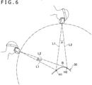
Fig. 6 is a diagram for explaining a function of a light shield portion. - [
Fig. 7 ]
Fig. 7 schematically illustrates a cross section of the light shield portion according to a modification example. - [
Fig. 8 ]
Fig. 8 schematically illustrates a cross section of the light shield portion according to another modification example. - [
Fig. 9 ]
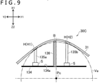
Fig. 9 schematically illustrates a cross section of the light shield portion according to still another modification example. - [
Fig. 10A ]
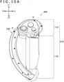
Fig. 10A is a back view of another example of the input device proposed in the present disclosure. - [
Fig. 10B ]
Fig. 10B is a side view of the example of the input device illustrated inFig. 10A . - [
Fig. 10C ]
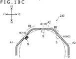
Fig. 10C schematically illustrates a cross section of the tracked unit taken along an Xc-Xc line inFig. 10B . - Description will be made below on an example of an input device proposed in the present disclosure. Herein, directions represented by Z1 and Z2 in
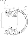
Fig. 2 are respectively referred to as up and down, directions represented by X1 and X2 inFig. 2 are respectively referred to as right and left, and directions represented by Y1 and Y2 inFig. 3 are respectively referred to as front and rear. These directions correspond to directions of view from a user who grasps and uses aninput device 100 as illustrated inFig. 1 . - As illustrated in
Fig. 1 , theinput device 100 is used with, for example, a head mounted display (HMD) 2. The user wears theHMD 2 on his or her head and holds theinput device 100 in his or her right hand and/or left hand. The HMD 2 includes a camera facing forward. Theinput device 100 is provided with a plurality of light-emitting units H described later. Positions of the light-emitting units H are detected through the camera and a position and an attitude of the input device 100 (i.e., a position and an orientation of the hand of the user) are calculated on the basis of the positions of the light-emitting units. Theinput device 100 includes a plurality of operation units (for example, an operation button, an operation stick, and a touch sensor) for the user to operate with a finger as described later. A display of theHMD 2 shows a moving image (for example, a game image) generated on the basis of the position of theinput device 100, the attitude thereof, an operation performed on the operation units, etc. - The position and attitude of the
input device 100 may be calculated by an information processing device installed in theHMD 2 or by an external information processing device (for example, a game device independent of theHMD 2 or a personal computer). Theinput device 100 may include a motion sensor (for example, an acceleration sensor or a gyroscope sensor). The information processing device may calculate the position and attitude of theinput device 100 on the basis of not only the positions of the light-emitting units H but also an output from the motion sensor. Further, the moving image may be generated by the information processing device installed in theHMD 2 or by the external information processing device. In a case where the external information processing device calculates the position of theinput device 100, etc. and generates the moving image, image information obtained by the camera of theHMD 2 is sent to the external information processing device wirelessly or by wire. Moving image information generated by the external information processing device is sent to theHMD 2 wirelessly or by wire. - It should be noted that the
input device 100 may be used independently of theHMD 2 not as in the system illustrated as an example inFig. 1 . In this case, the camera for tracking the position and attitude of theinput device 100 is not necessarily provided in theHMD 2 and may be disposed at a position distant forward from the user. For example, the camera may be attached to an external display device (for example, a monitor of a television or a personal computer) for displaying the moving image generated on the basis of the position and attitude of theinput device 100. - An outline of the
input device 100 for a right hand and an outline of theinput device 100 for a left hand may be bilaterally symmetric. A detailed description will be made below on theinput device 100 for a right hand. - As illustrated in
Fig. 2 , abody 10 of theinput device 100 includes agrip 11B and anoperation region 11A where the plurality of operation units are disposed. Thebody 10 has theoperation region 11A in an upper portion thereof, and thegrip 11B extends downward from theoperation region 11A. The operation units disposed in theoperation region 11A are able to be operated with a thumb or an index finger with thegrip 11B grasped. Thegrip 11B is held with, for example, a ball of the thumb, a middle finger, a ring finger, and a little finger. - As illustrated in
Fig. 2 andFig. 3 , for example,operation buttons operation stick 16 are disposed as the operation units in theoperation region 11A. Theoperation button 13 is disposed on afront surface 11a of theoperation region 11A (seeFig. 3 ) and is to be operated with, for example, the index finger. Theoperation buttons operation stick 16 are disposed on aback surface 11b of theoperation region 11A (seeFig. 2 ) and are to be operated with, for example, the thumb. Theoperation stick 16 is an operation unit that is tiltable in a radial direction and slidable. The operation units provided in theoperation region 11A are not limited to the example described herein. For example, a touch sensor, a trigger button, a touch-sensor-equipped button may be provided in theoperation region 11A. Further, the number of the operation units provided in theoperation region 11A may be one, two, or four or more. - As illustrated in
Fig. 2 , theinput device 100 includes a trackedunit 30 in which the plurality of light-emitting units H are disposed (in the figure, the light-emitting units are illustrated as filled circles). In the example illustrated in the figure, the trackedunit 30 is located on a right side of thebody 10, being coupled to an uppermost portion of thebody 10 and a lowermost portion of thebody 10. The trackedunit 30 extends downward from the uppermost portion of thebody 10 while curved to project outward in a right-and-left direction. - The tracked
unit 30 is not limited in position and shape to the example illustrated in the figure as long as being at a position for the light-emitting units H to be stably detected by the camera installed in theHMD 2. For example, the trackedunit 30 may be located on a left side of thebody 10 or may be located on an upper side, a lower side, a rear side, or a front side of thebody 10. Further, the shape of the trackedunit 30 may be, instead of a curved bar-shape, a bar-shape extending straight or an annular shape. In a case where the shape of the trackedunit 30 is an annular shape, the trackedunit 30 may be disposed such that it surrounds a hand or a wrist of the user who grasps thegrip 11B. - Another light-emitting unit H may be provided also in the
body 10. For example, another plurality of light-emitting units H may be provided in thefront surface 11a or theback surface 11b of theoperation region 11A or another plurality of light-emitting units H may be provided in alower portion 11e of thegrip 11B as illustrated inFig. 2 . - A detailed description will be made below on a structure of the tracked
unit 30. Directions referred to in the description below are used to explain relative positional relations among elements (components, members, and portions) of the trackedunit 30 and are not intended to limit the position of the trackedunit 30 in theinput device 100. - As illustrated in
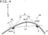
Fig. 4 , the trackedunit 30 includes anexterior member 31 that provides an outer surface A of the trackedunit 30 and a plurality of light sources S disposed inside theexterior member 31. For example, a light-emitting diode (LED) is usable as each of the light sources S. For example, the light sources S are disposed inside theexterior member 31 along theexterior member 31. In this case, positions of the plurality of light sources S correspond one-to-one to the positions of the light-emitting units H. For example, the light sources S are mounted on a flexible printed circuit board (FPC) supported by a frame not illustrated. Theexterior member 31 is formed of, for example, an opaque material. Theexterior member 31 itself may be formed of an opaque material, or a surface of theexterior member 31 is coated with a material that lets no light through. In a case where theexterior member 31 is formed of an opaque material, theexterior member 31 is formed of a material that lets light through only at the positions of the light-emitting units H. Theexterior member 31 may be provided with holes which let light through, at the positions of the light-emitting units H. - As illustrated in
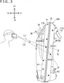
Fig. 4 , the outer surface A includes a first outer surface A1 and a second outer surface A2. The two outer surfaces A1 and A2 extend in an extending direction of the trackedunit 30 and are arranged side by side in a direction perpendicular to the extending direction. In the example of theinput device 100, the trackedunit 30 is curved, extending in an up-and-down direction and projecting rightward (seeFig. 2 ). The two outer surfaces A1 and A2 are thus curved, extending in the up-and-down direction and projecting rightward as illustrated inFig. 3 . The outer surfaces A1 and A2 are formed adjacent to each other in a front-and-rear direction and are continuous with each other. In the example of theinput device 100, the outer surface A is gently curved from the first outer surface A1 to the second outer surface A2. The outer surface A may be bent between the two outer surfaces A1 and A2 with an angle made therebetween. As illustrated inFig. 3 , the two outer surfaces A1 and A2 are each provided with the plurality of light-emitting units H. In each of the outer surfaces A1 and A2, the plurality of light-emitting units H are arranged side by side in the extending direction of the trackedunit 30. - A facing direction of the first outer surface A1 (a direction of a normal line D1 in
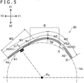
Fig. 5 ) and a facing direction of the second outer surface A2 (a direction of a normal line D2 inFig. 5 ) are different from each other. In the example of theinput device 100, the outer surface A1 faces rearward and rightward and the outer surface A2 faces forward and rightward (inFig. 5 , X1, Y1, and Y2 represent rightward, forward, and rearward with respect to theinput device 100, respectively) in a cross section taken along a plane perpendicular to the extending direction of the tracked unit 30 (for example, a horizontal plane). - As illustrated in
Fig. 3 , when theinput device 100 is looked at through the camera installed in theHMD 2, there is an angle θ, which is determined by a relative position between theinput device 100 and the camera, made between a straight line L1 connecting the light-emitting unit H in the first outer surface A1 and the camera and a straight line L2 connecting the light-emitting unit H in the second outer surface A2 and the camera. The angle θ becomes smaller depending on the relative position between theinput device 100 and the camera, which would cause the two light-emitting units H to overlap each other in an image captured by the camera. This has an influence on tracking accuracy (accuracy in calculation of the position and attitude) of theinput device 100. - Accordingly, in the example of the
input device 100, a light shield portion B is provided in the trackedunit 30 as illustrated inFig. 4 . The light shield portion B, which is a part of theexterior member 31, is located between a light-emitting unit H1 in the first outer surface A1 and a light-emitting unit H2 in the second outer surface A2. (The light-emitting units H1 and H2 are, among the plurality of light-emitting units H in the first outer surface A1 and the plurality of light-emitting units H in the second outer surface A2, respective two light-emitting units H that are least distant from each other.) The light shield portion B is a portion located further outside than the two light-emitting units H1 and H2. In other words, the light shield portion B is a portion located further outside than a straight line L3 connecting the two light-emitting units H1 and H2. In the example of theinput device 100, the light shield portion B is located on a right side with respect to the straight line L3. Such a light shield portion B allows for preventing the two light-emitting units H1 and H2 from overlapping each other in an image captured by the camera. As in the example illustrated inFig. 4 , a distance D from an apex portion Ap of the light shield portion B to the line L3 may be larger than a diameter R1 of the light-emitting units H. The distance D from the apex portion Ap of the light shield portion B to the line L3 may be 1.5 times or more as large as the diameter R1 of the light-emitting units H. - It is desirable that, when viewed in a cross section taken along a plane perpendicular to the extending direction of the tracked
unit 30, the light shield portion B include a portion located further outside than a virtual arc Va that is in contact with the first outer surface A1 and the second outer surface A2 as illustrated inFig. 5 . The arc Va is, for example, an arc that is in contact with the first outer surface A1 at a position of the light-emitting unit H1 of the first outer surface A1 and in contact with the second outer surface A2. In a case where a width W2 of the second outer surface A2 is smaller, the arc Va may be, for example, an arc that is in contact with the first outer surface A1 at the position of the light-emitting unit H1 of the first outer surface A1 and in contact with a virtual plane including the second outer surface A2. The arc Va is a part of a true circle having a center Pc. It should be noted that, in the example of theinput device 100, a distance N1 from the apex portion Ap of the outer surface A to the light-emitting unit H1 is larger than a distance N2 from the apex portion Ap of the outer surface A to the light-emitting unit H2 as described later. The above-described arc Va is an arc defined by, out of the two light-emitting units H1 and H2, the light-emitting unit H1 with a larger distance. - By virtue of the presence of such a light shield portion B, it is possible to effectively prevent the two light-emitting units H1 and H2 from overlapping each other in an image captured by the camera. For example, as illustrated in
Fig. 6 , in a case where the angle θ between the straight line L1, which connects the light-emitting unit H1 and the camera, and the straight line L2, which connects the light-emitting unit H2 and the camera, becomes θlim due to the camera being located on a rear side of theinput device 100, the straight line L2 intersects with the light shield portion B, causing the light-emitting unit H2 not to be seen in an image captured by the camera. - As illustrated in
Fig. 3 , the light shield portion B extends in the extending direction of the trackedunit 30. It is desirable that the light shield portion B be formed across a whole region where the light-emitting units H are provided in the trackedunit 30. A position of the light shield portion B is not limited to the example of theinput device 100. For example, the light shield portion B may be intermittently formed in the extending direction of the trackedunit 30. For example, while the light shield portion B is formed for two of the light-emitting units H with a small distance therebetween (the light-emitting unit H of the first outer surface A1 and the light-emitting unit H of the second outer surface A2), the light shield portion B is not necessarily formed between two of the light-emitting units H with a large distance therebetween (another light-emitting unit H of the first outer surface A1 and another light-emitting unit H of the second outer surface A2). - It should be noted that the "outer surface A" herein, which refers to a surface provided by a member in an outermost surface of the tracked
unit 30, is provided by an opaque exterior member or a transparent exterior member. The "light-emitting unit H" refers to a portion of the exterior member that lets light through. For example, as illustrated inFig. 4 andFig. 5 , in a structure in which theexterior member 31 is formed of an opaque material and a material or holes that let light through are formed at positions of the light sources S, portions where the material that lets light through is formed or portions where the holes that let light through are formed are the light-emitting units H. In contrast, in a later-described structure in which a transparent exterior member is disposed in the outermost surface of the trackedunit 30 and the light sources S are disposed inside the exterior member (seeFig. 7 ), portions facing the light sources S are the light-emitting units H. Alternatively, in a later-described structure in which a transparent exterior member is disposed in the outermost surface of the trackedunit 30, light guide members are disposed inside the exterior member, and light from the light sources S is to be guided by the light guide members (seeFig. 8 andFig. 9 ), portions facing end surfaces (light outgoing surfaces) of the light guide members are the light-emitting units H. A direction of an optical axis of each of the light-emitting units H is substantially the same as the facing directions of the outer surfaces A1 and A2. - As illustrated in
Fig. 5 , the light shield portion B is formed as, for example, a part of theopaque exterior member 31. This structure allows for ensuring the light shield portion B without the necessity of increasing the number of components. In the example of theinput device 100, a part of the outer surface A including a boundary between the first outer surface A1 and the second outer surface A2 functions as the light shield portion B. In more detail, a ridge (in other words, a corner) is formed between the first outer surface A1 and the second outer surface A2 continuous therewith, and the ridge functions as the light shield portion B. It should be noted that, instead of the ridge being caused to function as the light shield portion B, for example, theexterior member 31 may have a rib (wall) formed integrally with theexterior member 31 between the first outer surface A1 and the second outer surface A2, the rib functioning as the light shield portion B. - In still another example, the light shield portion B may be a member formed independent of the
exterior member 31. For example, the light shield portion B may be formed of a material such as sponge, silicone, rubber, or plastic independent of theexterior member 31 and attached to theexterior member 31 or a frame of the trackedunit 30. - Further, in the example of the
input device 100, the first outer surface A1 is located on a rear side with respect to the second outer surface A2 as illustrated inFig. 3 . This causes the first outer surface A1 to be, when the user holds theinput device 100, a surface closer to the camera than the second outer surface A2, i.e., a surface closer to a body of the user. The first outer surface A1 is thus more likely to appear in an image captured by the camera than the second outer surface A2. As illustrated inFig. 5 , when a cross section perpendicular to the extending direction of the trackedunit 30 is viewed, a width W1 of the first outer surface A1 is larger than the width W2 of the second outer surface A2. This means that, in the example of theinput device 100, the width W1 of the first outer surface A1, which is closer to the camera, is larger than the width W2 of the second outer surface A2, which is more distant from the camera. This structure allows for increasing flexibility in the positions and number of the light-emitting units H provided in the first outer surface A1. As a result, an improvement in tracking accuracy is facilitated as compared with a case where the width W2 of the second outer surface A2 is larger than the width W1 of the first outer surface A1. - Further, as illustrated in
Fig. 5 , when a cross section perpendicular to the extending direction of the trackedunit 30 is viewed, the distance N1 from the apex portion Ap between the first outer surface A1 and the second outer surface A2 to the light-emitting unit H1 is larger than the distance N2 from the apex portion Ap to the light-emitting unit H2. (The apex portion Ap refers to a portion having a largest curvature in the outer surface A of the trackedunit 30 when the cross section of the trackedunit 30 is viewed.) This relation in distance may be satisfied by another light-emitting unit H provided in the first outer surface A1 and another light-emitting unit H provided in the second outer surface A2. This structure of the trackedunit 30 increases, in an image captured by the camera, a background formed in the vicinity of the light-emitting unit H1 of the first outer surface A1. For example, it is possible to prevent a pattern or illumination light of a room where theinput device 100 is used from appearing immediately near the light-emitting unit H1 in an image captured by the camera. As a result, the light-emitting unit H1 is likely to be correctly recognized through the camera to improve the tracking accuracy. - It is desirable that the light-emitting units H be located within, within a range of the width W1 in a front-and-rear direction of the first outer surface A1, a range W3 corresponding to two-thirds of the width W1 from a rear end Ae of the first outer surface A1. In other words, it is desirable that the light-emitting units H be located within the range W3 corresponding to two-thirds of the width W1 from the end portion Ae in a direction toward the camera. It is more desirable that the light-emitting units H be located within a range corresponding to one-half of the width W1 from the end portion Ae in the direction toward the camera.
- As illustrated in
Fig. 3 , the first outer surface A1 is provided with the plurality of light-emitting units H arranged side by side in the extending direction of the trackedunit 30 and the second outer surface A2 is likewise provided with the plurality of second light-emitting units H arranged side by side in the extending direction. This allows for improving the tracking accuracy. In the example of theinput device 100, the number of the light-emitting units H provided in the first outer surface A1 is larger than the number of the light-emitting units H in the second outer surface A2. This means that the number of the light-emitting units H that are likely to appear in an image captured by the camera is larger. - Further, as illustrated in
Fig. 3 , the positions of the light-emitting units H in the first outer surface A1 and the positions of the light-emitting units H in the second outer surface A2 are offset from each other in the extending direction of the tracked unit 30 (in the up-and-down direction in the example of the input device 100). This ensures a sufficient distance between the light-emitting units H in the first outer surface A1 and the light-emitting units H in the second outer surface A2, which also results in making the angle θ between the straight line L1, which connects the light-emitting unit H in the first outer surface A1 and the camera, and the straight line L2, which connects the light-emitting unit H in the second outer surface A2 and the camera, likely to be sufficiently ensured. - The light shield portion B may be provided by a member different from the
exterior member 31.Fig. 7 to Fig. 9 are diagrams for explaining modification examples of the trackedunit 30. In these figures, the same reference signs as those for the sections described so far are used. - In an example illustrated in
Fig. 7 , a trackedunit 30A includes aframe 33 disposed inside theexterior member 31 and supporting the light sources S. With the light sources S mounted on a substrate, which is not illustrated, the substrate may be attached to theframe 33. Theexterior member 31 is formed of a transparent material. In this case, a part of theframe 33 may serve as the light shield portion B. The light shield portion B is likewise located outside the virtual arc Va. This structure allows theframe 33, which supports the light sources S, to function as the light shield portion B to reduce an increase in the number of components. - In an example illustrated in
Fig. 8 , a trackedunit 30B includes asubstrate 34 disposed along an extending direction of the trackedunit 30B andlight guide members first substrate surface 34a andsecond substrate surface 34b) of thesubstrate 34. Thesubstrate 34 is, for example, a rigid substrate. Thesubstrate 34 is disposed with thefirst substrate surface 34a facing the first outer surface A1 and thesecond substrate surface 34b facing the second outer surface A2. Light from the light source S mounted on thefirst substrate surface 34a is guided through thelight guide member 35a to the light-emitting unit H1 in the first outer surface A1, and light from the light source S mounted on thesecond substrate surface 34a is guided through thelight guide member 35b to the light-emitting unit H2 in the second outer surface A2. Theexterior member 31 is formed of a transparent material. In this structure, a part of thesubstrate 34 may function as the light shield portion B. The light shield portion B is likewise located outside the virtual arc Va. - In the example illustrated in
Fig. 8 , thesubstrate 34 is disposed along the apex portion Ap of the outer surface A. That is, a position of thesubstrate 34 in the front-and-rear direction corresponds to a position of the apex portion Ap. However, thesubstrate 34 may be offset rearward (a Y2 direction) from the position of the apex portion Ap as illustrated by a chain double-dashed line in the figure or, inversely, may be offset forward (a Y1 direction). - In an example illustrated in
Fig. 9 , a trackedunit 30C includes asubstrate 134 disposed along an extending direction of the trackedunit 30C,light guide members wall member 136. The light sources S are mounted only on one surface, asubstrate surface 134a, of thesubstrate 134. Thesubstrate 134 is disposed with thesubstrate surface 134a facing the first outer surface A1 and the second outer surface A2. Light from the two light sources S mounted on thesubstrate surface 134a is guided through thelight guide members exterior member 31 is formed of a material that is transparent or that lets light through. Thewall member 136 is disposed upright with respect to thesubstrate 134 and has a part that functions as the light shield portion B. The light shield portion B is likewise located outside the virtual arc Va. - In an
input device 200 illustrated inFig. 10A to Fig. 10C , a trackedunit 230 is located on a left side of abody 210. The trackedunit 230 has the first outer surface A1, the second outer surface A2, and a third outer surface A3, which extend in an extending direction of the trackedunit 230. The three outer surfaces A1, A2, and A3 are arranged side by side in a direction perpendicular to the extending direction of the tracked unit 230 (in the example of theinput device 200, the front-and-rear direction). The light-emitting units H are provided in the outer surfaces A1, A2, and A3. - As illustrated in
Fig. 10C , a light shield portion B1 is located between the light-emitting unit H1 in the first outer surface A1 and the light-emitting unit H2 in the second outer surface A2. A light shield portion B2 is located between the light-emitting unit H2 in the second outer surface A2 and a light-emitting unit H3 in the third outer surface A3. The light shield portion B1 has a portion located further outside than the two light-emitting units H1 and H2, and the light shield portion B2 has a portion located further outside than the two light-emitting units H2 and H3. - Further, a relation between the light-emitting units H1 and H2, the outer surfaces A1 and A2, and the light shield portion B1 illustrated in
Fig. 10C may be the same as the relation between the light-emitting units H1 and H2 and the light shield portion B described with reference toFig. 5 . A relation between the light-emitting units H2 and H3, the outer surfaces A2 and A3, and the light shield portion B2 illustrated inFig. 10C may be the same as the relation between the light-emitting units H1 and H2 and the light shield portion B described with reference toFig. 5 . That is, it is desirable that the light shield portion B1 have a portion located further outside than the virtual arc Va that is in contact with the first outer surface A1 and the second outer surface A2. Likewise, it is desirable that the light shield portion B2 also have a portion located further outside than the virtual arc Va that is in contact with the second outer surface A2 and the third outer surface A3. (The arc that is in contact with the two outer surfaces A1 and A2 and the arc that is in contact with the two outer surfaces A2 and A3 are not necessarily the same.) This is the description on theinput device 200 illustrated inFig. 10A to Fig. 10C . - In still another example, the shape of the tracked
unit 30 may be an annular shape. In this case, the two outer surfaces A1 and A2 extend in a circumferential direction and are arranged side by side in a direction vertical to the circumferential direction (a direction along a center line of the annular tracked unit 30). Further, the light shield portion B, which likewise extends in the circumferential direction, is formed between the adjacent two outer surfaces A1 and A2. - In the example of the
input device 100, the light shield portion B is formed across the whole region where the light-emitting units H are provided in the trackedunit 30. However, the light shield portion B may be provided only between one of the light-emitting units H provided in the first outer surface A1 and one of the light-emitting units H provided in the second outer surface A2. - In yet another example, the
input device 100 does not necessarily include the operation units that are to be operated with a finger, such as theoperation buttons operation stick 16. Even in this case, the user may be able to reflect, by moving theinput device 100 with thegrip 11B held, the motion in a moving image displayed on theHMD 2. - As described above, the camera for tracking the position and attitude of the
input device 100 is not necessarily provided in theHMD 2 and may be disposed at a position distant forward from the user. For example, the camera may be attached to an external display device (for example, a monitor of a television or a personal computer) for displaying the moving image generated based on the position and attitude of theinput device 100. - Further, a type of the camera for tracking the position and attitude of the
input device 100 is not limited. The camera may include an image sensor that detects visible light or may be an infrared image sensor. Alternatively, the camera may be equipped with a sensor (Dynamic vision sensor, Event Driven Sensor, or the like) that outputs only information regarding, within a whole angle of view, a pixel that has undergone a change.
Claims (11)
- An input device comprising:a grip; anda tracked unit including a plurality of light-emitting units, the tracked unit extending in one direction, whereinthe tracked unit includesa first outer surface provided with a first light-emitting unit, the first outer surface extending in an extending direction of the tracked unit,a second outer surface provided with a second light-emitting unit, the second outer surface extending in the extending direction of the tracked unit, anda light shield portion,the first outer surface and the second outer surface are arranged side by side in a direction perpendicular to the extending direction of the tracked unit,the first outer surface faces a first direction,the second outer surface faces a second direction different from the first direction, andthe light shield portion is located further outside than the first light-emitting unit and the second light-emitting unit.
- The input device according to claim 1, wherein
the light shield portion includes a portion located further outside than a virtual arc that is in contact with the first outer surface and the second outer surface. - The input device according to claim 1, wherein
the light shield portion includes a portion located at a position outside a virtual arc that is in contact with the first outer surface at a position of the first light-emitting unit and in contact with the second outer surface or a virtual plane including the second outer surface. - The input device according to claim 1, whereinthe first outer surface is provided with a plurality of first light-emitting units arranged side by side in the extending direction of the tracked unit, andthe second outer surface is provided with a plurality of second light-emitting units arranged side by side in the extending direction of the tracked unit.
- The input device according to claim 4, wherein
positions of the plurality of first light-emitting units and positions of the plurality of second light-emitting units are offset from each other in the extending direction of the tracked unit. - The input device according to claim 1, wherein,
in a cross section perpendicular to the extending direction of the tracked unit, a distance from an apex portion between the first outer surface and the second outer surface to the first light-emitting unit is larger than a distance from the apex portion to the second light-emitting unit. - The input device according to claim 1, wherein,
in a cross section perpendicular to the extending direction of the tracked unit, a width of the first outer surface is larger than a width of the second outer surface. - The input device according to claim 1, wherein
an outer surface of the tracked unit including a boundary between the first outer surface and the second outer surface is configured to function as the light shield portion. - The input device according to claim 1, further comprising:
an exterior member that includes the first outer surface and the second outer surface, the exterior member including a portion configured to function as the light shield portion. - The input device according to claim 1, wherein
the tracked unit includes a frame disposed inside the first outer surface and the second outer surface and supporting a light source, the frame including a portion configured to function as the light shield portion. - The input device according to claim 1, whereinthe first outer surface is provided with a plurality of first light-emitting units arranged side by side in the extending direction of the tracked unit,the second outer surface is provided with a plurality of second light-emitting units arranged side by side in the extending direction of the tracked unit, andthe light shield portion extends in the extending direction of the tracked unit.
Applications Claiming Priority (2)
| Application Number | Priority Date | Filing Date | Title |
|---|---|---|---|
| JP2019050278 | 2019-03-18 | ||
| PCT/JP2020/011828 WO2020189691A1 (en) | 2019-03-18 | 2020-03-17 | Input device |
Publications (2)
| Publication Number | Publication Date |
|---|---|
| EP3944059A1 true EP3944059A1 (en) | 2022-01-26 |
| EP3944059A4 EP3944059A4 (en) | 2022-12-21 |
Family
ID=72520162
Family Applications (1)
| Application Number | Title | Priority Date | Filing Date |
|---|---|---|---|
| EP20774631.4A Pending EP3944059A4 (en) | 2019-03-18 | 2020-03-17 | INPUT DEVICE |
Country Status (5)
| Country | Link |
|---|---|
| US (2) | US12602104B2 (en) |
| EP (1) | EP3944059A4 (en) |
| JP (2) | JP7328322B2 (en) |
| CN (2) | CN113544628B (en) |
| WO (1) | WO2020189691A1 (en) |
Cited By (5)
| Publication number | Priority date | Publication date | Assignee | Title |
|---|---|---|---|---|
| EP4289488A1 (en) * | 2022-06-10 | 2023-12-13 | Sony Interactive Entertainment Inc. | Hybrid pixel dynamic vision sensor tracking using ir and ambient light (or depth sensor) |
| US11995226B2 (en) | 2022-06-10 | 2024-05-28 | Sony Interactive Entertainment Inc. | Dynamic vision sensor tracking based on light source occlusion |
| US12059609B2 (en) | 2022-06-10 | 2024-08-13 | Sony Interactive Entertainment Inc. | Asynchronous dynamic vision sensor LED AI tracking system and method |
| US12064682B2 (en) | 2022-06-10 | 2024-08-20 | Sony Interactive Entertainment Inc. | Deployment of dynamic vision sensor hybrid element in method for tracking a controller and simultaneous body tracking, slam or safety shutter |
| US12210674B2 (en) | 2022-06-10 | 2025-01-28 | Sony Interactive Entertainment Inc. | Dynamic vision sensor based eye and/or facial tracking |
Family Cites Families (20)
| Publication number | Priority date | Publication date | Assignee | Title |
|---|---|---|---|---|
| WO2007005932A2 (en) | 2005-07-01 | 2007-01-11 | Hillcrest Laboratories, Inc. | 3d pointing devices |
| US20070080940A1 (en) * | 2005-10-07 | 2007-04-12 | Sharp Kabushiki Kaisha | Remote control system, and display device and electronic device using the remote control system |
| US8344325B2 (en) * | 2009-05-22 | 2013-01-01 | Motorola Mobility Llc | Electronic device with sensing assembly and method for detecting basic gestures |
| JP5161900B2 (en) | 2010-02-09 | 2013-03-13 | 株式会社ソニー・コンピュータエンタテインメント | Operation device |
| EP2634670A1 (en) | 2012-03-01 | 2013-09-04 | Asplund Data AB | A data input device |
| KR102138510B1 (en) * | 2013-08-27 | 2020-07-28 | 엘지전자 주식회사 | Electronic device for sensing proximity touch and controlling method thereof |
| JP6669069B2 (en) | 2014-09-10 | 2020-03-18 | ソニー株式会社 | Detection device, detection method, control device, and control method |
| US9898091B2 (en) * | 2015-06-03 | 2018-02-20 | Oculus Vr, Llc | Virtual reality system with head-mounted display, camera and hand-held controllers |
| US9983709B2 (en) | 2015-11-02 | 2018-05-29 | Oculus Vr, Llc | Eye tracking using structured light |
| US10007339B2 (en) * | 2015-11-05 | 2018-06-26 | Oculus Vr, Llc | Controllers with asymmetric tracking patterns |
| US9977494B2 (en) * | 2015-12-30 | 2018-05-22 | Oculus Vr, Llc | Tracking constellation assembly for use in a virtual reality system |
| JP6881896B2 (en) | 2016-04-20 | 2021-06-02 | キヤノン株式会社 | Head mounting device and gripping device |
| JP6731787B2 (en) | 2016-06-02 | 2020-07-29 | 株式会社Subaru | Fiber-reinforced composite material manufacturing method and perforating/joining device |
| US20170354864A1 (en) | 2016-06-11 | 2017-12-14 | Sony Interactive Entertainment Inc. | Directional Interface Object |
| CN205899500U (en) | 2016-07-27 | 2017-01-18 | 上海拆名晃信息科技有限公司 | A handle for realizing human -computer interaction |
| US10549183B2 (en) * | 2016-10-11 | 2020-02-04 | Valve Corporation | Electronic controller with a hand retainer, outer shell, and finger sensing |
| JP6242473B1 (en) | 2016-12-22 | 2017-12-06 | 株式会社コロプラ | Method for providing virtual space, program for causing computer to execute the method, and information processing apparatus for executing the program |
| US10579151B2 (en) * | 2017-01-04 | 2020-03-03 | Htc Corporation | Controller for finger gesture recognition and method for recognizing finger gesture |
| JP2018016493A (en) | 2017-11-01 | 2018-02-01 | 東芝テック株式会社 | Work support device and program |
| JP2019012536A (en) | 2018-08-17 | 2019-01-24 | 株式会社コロプラ | Information providing method, program, and information providing apparatus |
-
2020
- 2020-03-17 US US17/436,232 patent/US12602104B2/en active Active
- 2020-03-17 WO PCT/JP2020/011828 patent/WO2020189691A1/en not_active Ceased
- 2020-03-17 JP JP2021507381A patent/JP7328322B2/en active Active
- 2020-03-17 EP EP20774631.4A patent/EP3944059A4/en active Pending
- 2020-03-17 CN CN202080019738.6A patent/CN113544628B/en active Active
- 2020-03-17 CN CN202411024729.2A patent/CN119088209A/en active Pending
-
2023
- 2023-08-03 JP JP2023127005A patent/JP7568799B2/en active Active
-
2024
- 2024-07-29 US US18/787,253 patent/US20240385680A1/en active Pending
Cited By (6)
| Publication number | Priority date | Publication date | Assignee | Title |
|---|---|---|---|---|
| EP4289488A1 (en) * | 2022-06-10 | 2023-12-13 | Sony Interactive Entertainment Inc. | Hybrid pixel dynamic vision sensor tracking using ir and ambient light (or depth sensor) |
| US11995226B2 (en) | 2022-06-10 | 2024-05-28 | Sony Interactive Entertainment Inc. | Dynamic vision sensor tracking based on light source occlusion |
| US12029971B2 (en) | 2022-06-10 | 2024-07-09 | Sony Interactive Entertainment LLC | Hybrid pixel dynamic vision sensor tracking using IR and ambient light (or depth sensor) |
| US12059609B2 (en) | 2022-06-10 | 2024-08-13 | Sony Interactive Entertainment Inc. | Asynchronous dynamic vision sensor LED AI tracking system and method |
| US12064682B2 (en) | 2022-06-10 | 2024-08-20 | Sony Interactive Entertainment Inc. | Deployment of dynamic vision sensor hybrid element in method for tracking a controller and simultaneous body tracking, slam or safety shutter |
| US12210674B2 (en) | 2022-06-10 | 2025-01-28 | Sony Interactive Entertainment Inc. | Dynamic vision sensor based eye and/or facial tracking |
Also Published As
| Publication number | Publication date |
|---|---|
| JP7568799B2 (en) | 2024-10-16 |
| EP3944059A4 (en) | 2022-12-21 |
| CN113544628A (en) | 2021-10-22 |
| JP2023145707A (en) | 2023-10-11 |
| CN119088209A (en) | 2024-12-06 |
| US20240385680A1 (en) | 2024-11-21 |
| JP7328322B2 (en) | 2023-08-16 |
| CN113544628B (en) | 2024-08-16 |
| JPWO2020189691A1 (en) | 2020-09-24 |
| US12602104B2 (en) | 2026-04-14 |
| US20220155848A1 (en) | 2022-05-19 |
| WO2020189691A1 (en) | 2020-09-24 |
Similar Documents
| Publication | Publication Date | Title |
|---|---|---|
| US20240385680A1 (en) | Input Device | |
| US11816296B2 (en) | External user interface for head worn computing | |
| US12216821B2 (en) | External user interface for head worn computing | |
| US9335547B2 (en) | Head-mounted display device and method of controlling head-mounted display device | |
| US10191281B2 (en) | Head-mounted display for visually recognizing input | |
| US11199902B2 (en) | Input device | |
| JP7704824B2 (en) | Input devices | |
| US20170017323A1 (en) | External user interface for head worn computing | |
| US20150205351A1 (en) | External user interface for head worn computing | |
| JP2009104429A (en) | Head mounted display device and portable device | |
| EP3943167A1 (en) | Device provided with plurality of markers | |
| JP2021056371A (en) | Display system, display method, and display program | |
| US12242099B2 (en) | Input device | |
| US20240402901A1 (en) | Devices, methods, and graphical user interfaces for scrolling content | |
| JP3126898B2 (en) | Head-mounted display device | |
| JP2021047771A (en) | Control device, imaging device, control method, and program | |
| CN121057991A (en) | Wearable devices and methods for moving virtual objects using gestures | |
| US20240377899A1 (en) | Input device | |
| EP4738090A2 (en) | Devices, methods, and graphical user interfaces for interacting with three-dimensional environments | |
| CN111701228B (en) | Input devices | |
| EP3531247B1 (en) | Traceable optical device |
Legal Events
| Date | Code | Title | Description |
|---|---|---|---|
| STAA | Information on the status of an ep patent application or granted ep patent |
Free format text: STATUS: THE INTERNATIONAL PUBLICATION HAS BEEN MADE |
|
| PUAI | Public reference made under article 153(3) epc to a published international application that has entered the european phase |
Free format text: ORIGINAL CODE: 0009012 |
|
| STAA | Information on the status of an ep patent application or granted ep patent |
Free format text: STATUS: REQUEST FOR EXAMINATION WAS MADE |
|
| 17P | Request for examination filed |
Effective date: 20210908 |
|
| AK | Designated contracting states |
Kind code of ref document: A1 Designated state(s): AL AT BE BG CH CY CZ DE DK EE ES FI FR GB GR HR HU IE IS IT LI LT LU LV MC MK MT NL NO PL PT RO RS SE SI SK SM TR |
|
| DAV | Request for validation of the european patent (deleted) | ||
| DAX | Request for extension of the european patent (deleted) | ||
| A4 | Supplementary search report drawn up and despatched |
Effective date: 20221121 |
|
| RIC1 | Information provided on ipc code assigned before grant |
Ipc: G06F 3/03 20060101ALI20221115BHEP Ipc: G06F 3/0346 20130101ALI20221115BHEP Ipc: G06F 3/01 20060101AFI20221115BHEP |
|
| STAA | Information on the status of an ep patent application or granted ep patent |
Free format text: STATUS: EXAMINATION IS IN PROGRESS |
|
| 17Q | First examination report despatched |
Effective date: 20240328 |