EP3943998A1 - Endoscope connector device - Google Patents
Endoscope connector device Download PDFInfo
- Publication number
- EP3943998A1 EP3943998A1 EP20773654.7A EP20773654A EP3943998A1 EP 3943998 A1 EP3943998 A1 EP 3943998A1 EP 20773654 A EP20773654 A EP 20773654A EP 3943998 A1 EP3943998 A1 EP 3943998A1
- Authority
- EP
- European Patent Office
- Prior art keywords
- case
- connector device
- exterior case
- endoscope
- wall part
- Prior art date
- Legal status (The legal status is an assumption and is not a legal conclusion. Google has not performed a legal analysis and makes no representation as to the accuracy of the status listed.)
- Granted
Links
Images





Classifications
-
- G—PHYSICS
- G02—OPTICS
- G02B—OPTICAL ELEMENTS, SYSTEMS OR APPARATUS
- G02B23/00—Telescopes, e.g. binoculars; Periscopes; Instruments for viewing the inside of hollow bodies; Viewfinders; Optical aiming or sighting devices
- G02B23/24—Instruments or systems for viewing the inside of hollow bodies, e.g. fibrescopes
- G02B23/2407—Optical details
- G02B23/2461—Illumination
- G02B23/2469—Illumination using optical fibres
-
- A—HUMAN NECESSITIES
- A61—MEDICAL OR VETERINARY SCIENCE; HYGIENE
- A61B—DIAGNOSIS; SURGERY; IDENTIFICATION
- A61B1/00—Instruments for performing medical examinations of the interior of cavities or tubes of the body by visual or photographical inspection, e.g. endoscopes; Illuminating arrangements therefor
- A61B1/00002—Operational features of endoscopes
- A61B1/00025—Operational features of endoscopes characterised by power management
- A61B1/00027—Operational features of endoscopes characterised by power management characterised by power supply
- A61B1/00029—Operational features of endoscopes characterised by power management characterised by power supply externally powered, e.g. wireless
-
- A—HUMAN NECESSITIES
- A61—MEDICAL OR VETERINARY SCIENCE; HYGIENE
- A61B—DIAGNOSIS; SURGERY; IDENTIFICATION
- A61B1/00—Instruments for performing medical examinations of the interior of cavities or tubes of the body by visual or photographical inspection, e.g. endoscopes; Illuminating arrangements therefor
- A61B1/00112—Connection or coupling means
- A61B1/00121—Connectors, fasteners and adapters, e.g. on the endoscope handle
-
- G—PHYSICS
- G02—OPTICS
- G02B—OPTICAL ELEMENTS, SYSTEMS OR APPARATUS
- G02B23/00—Telescopes, e.g. binoculars; Periscopes; Instruments for viewing the inside of hollow bodies; Viewfinders; Optical aiming or sighting devices
- G02B23/24—Instruments or systems for viewing the inside of hollow bodies, e.g. fibrescopes
- G02B23/2476—Non-optical details, e.g. housings, mountings, supports
-
- G—PHYSICS
- G02—OPTICS
- G02B—OPTICAL ELEMENTS, SYSTEMS OR APPARATUS
- G02B23/00—Telescopes, e.g. binoculars; Periscopes; Instruments for viewing the inside of hollow bodies; Viewfinders; Optical aiming or sighting devices
- G02B23/24—Instruments or systems for viewing the inside of hollow bodies, e.g. fibrescopes
- G02B23/2476—Non-optical details, e.g. housings, mountings, supports
- G02B23/2492—Arrangements for use in a hostile environment, e.g. a very hot, cold or radioactive environment
-
- H—ELECTRICITY
- H01—ELECTRIC ELEMENTS
- H01R—ELECTRICALLY-CONDUCTIVE CONNECTIONS; STRUCTURAL ASSOCIATIONS OF A PLURALITY OF MUTUALLY-INSULATED ELECTRICAL CONNECTING ELEMENTS; COUPLING DEVICES; CURRENT COLLECTORS
- H01R13/00—Details of coupling devices of the kinds covered by groups H01R12/70 or H01R24/00 - H01R33/00
- H01R13/46—Bases; Cases
- H01R13/52—Dustproof, splashproof, drip-proof, waterproof, or flameproof cases
- H01R13/5202—Sealing means between parts of housing or between housing part and a wall, e.g. sealing rings
-
- A—HUMAN NECESSITIES
- A61—MEDICAL OR VETERINARY SCIENCE; HYGIENE
- A61B—DIAGNOSIS; SURGERY; IDENTIFICATION
- A61B1/00—Instruments for performing medical examinations of the interior of cavities or tubes of the body by visual or photographical inspection, e.g. endoscopes; Illuminating arrangements therefor
- A61B1/00002—Operational features of endoscopes
- A61B1/00011—Operational features of endoscopes characterised by signal transmission
- A61B1/00016—Operational features of endoscopes characterised by signal transmission using wireless means
-
- H—ELECTRICITY
- H01—ELECTRIC ELEMENTS
- H01R—ELECTRICALLY-CONDUCTIVE CONNECTIONS; STRUCTURAL ASSOCIATIONS OF A PLURALITY OF MUTUALLY-INSULATED ELECTRICAL CONNECTING ELEMENTS; COUPLING DEVICES; CURRENT COLLECTORS
- H01R13/00—Details of coupling devices of the kinds covered by groups H01R12/70 or H01R24/00 - H01R33/00
- H01R13/62—Means for facilitating engagement or disengagement of coupling parts or for holding them in engagement
- H01R13/629—Additional means for facilitating engagement or disengagement of coupling parts, e.g. aligning or guiding means, levers, gas pressure electrical locking indicators, manufacturing tolerances
-
- H—ELECTRICITY
- H01—ELECTRIC ELEMENTS
- H01R—ELECTRICALLY-CONDUCTIVE CONNECTIONS; STRUCTURAL ASSOCIATIONS OF A PLURALITY OF MUTUALLY-INSULATED ELECTRICAL CONNECTING ELEMENTS; COUPLING DEVICES; CURRENT COLLECTORS
- H01R13/00—Details of coupling devices of the kinds covered by groups H01R12/70 or H01R24/00 - H01R33/00
- H01R13/66—Structural association with built-in electrical component
- H01R13/717—Structural association with built-in electrical component with built-in light source
- H01R13/7172—Conduits for light transmission
Definitions
- the present invention relates to a connector device for an endoscope, and particularly relates to a connector device for an endoscope connected to a processor device for an endoscope.
- a connector device for an endoscope comprising a power reception coil is disclosed in JP2016-67534A .
- a contactless power supply unit is composed of the power reception coil and a power feeding coil on a processor device for an endoscope side, and power necessary for an endoscope is supplied by the power supply unit from the processor device for an endoscope to the endoscope.
- the connector device of JP2016-67534A comprises an exterior case having a first connector case, a second connector case, and a third connector case in order from a side connected to the processor device for an endoscope, and the power reception coil is disposed at a position close to a surface connected to the processor device for an endoscope, inside the first connector case.
- the connector device comprising the power reception coil as in JP2016-67534A
- the positions of the power feeding coil of the processor device for an endoscope and the power reception coil of the connector device are accurately aligned.
- the present invention is devised in view of such circumstances, and an object thereof is to provide a connector device for an endoscope that can stably operate an endoscope.
- a connector device for an endoscope that is attachably and detachably connected to a processor device.
- the connector device for an endoscope comprises a hollow exterior case, an inner case that is accommodated inside the exterior case, a holding body that is used for disposing the inner case inside the exterior case, and a power reception unit to which power is supplied from a power feed unit of the processor device in a contactless manner.
- the exterior case has a side wall part that faces the power feed unit of the processor device.
- the inner case has an inner case wall part that is disposed to face and be spaced apart from the side wall part.
- the power reception unit is disposed on the inner case wall part.
- the power reception unit has a flat plate-shaped core and a coil that is spirally wound around the core, and the core is composed of a sintered ferrite core.
- the power reception unit is adhered to the inner case wall part by a thermosetting adhesive material.
- the holding body is a shaft-shaped member of which one end is fixed to the inner case wall part, a first lead-out hole, into which the shaft-shaped member is inserted and which leads the other end of the shaft-shaped member to an outside of the exterior case, is provided in the side wall part, and a first sealing member is arranged between an inner wall surface of the first lead-out hole and an outer wall surface of the shaft-shaped member.
- the processor device has a positioning hole, into which the other end of the shaft-shaped member is inserted, in a surface facing the side wall part, and the other end of the shaft-shaped member is inserted into the positioning hole, and the power reception unit is in a state of being positioned at a position facing the power feed unit.
- the first sealing member is an O-ring fitted to the outer wall surface of the shaft-shaped member.
- the exterior case is made of a resin
- the inner case is made of a metal
- the inner case is a shield case for shielding an electronic component.
- the exterior case has a cylindrical body
- the inner case is formed in a rectangular parallelepiped shape
- the inner case is accommodated in the exterior case in a posture in which a long side of the inner case is aligned with an axis of the cylindrical body.
- the exterior case has an opening portion to which a universal cable extending from an endoscope is connected, and a second sealing member is arranged between an inner wall surface of the opening portion and an outer wall surface of the universal cable.
- the second sealing member is an O-ring fitted to the outer wall surface of the universal cable.
- the opening portion of the exterior case is formed in a size that allows the endoscope, the universal cable, and a switch disposed member provided at the universal cable to be inserted therein.
- the connector device for an endoscope further comprises a light guide rod of which one end is disposed inside the exterior case, a second lead-out hole, into which the light guide rod is inserted and which leads the other end of the light guide rod to an outside of the exterior case, is provided in the side wall part, and a third sealing member is arranged between an inner wall surface of the second lead-out hole and an outer wall surface of the light guide rod.
- the third sealing member is an O-ring fitted to the outer wall surface of the light guide rod.
- the endoscope can be stably operated.
- Fig. 1 is a schematic configuration view of an endoscope system 1.
- the endoscope system 1 comprises an endoscope 100 and a processor device for an endoscope 200.
- the endoscope 100 is a rigid endoscope, such as a laparoscope, and comprises an elongated rigid insertion part 102 that is inserted into a body cavity, an L-shaped grip portion 104 continuously connected to a proximal end part of the insertion part 102, a flexible universal cable 106 of which a proximal end part is connected to the insertion part 102 via the grip portion 104, and a switch disposed member 108 provided in a middle portion of the universal cable 106.
- a rigid endoscope such as a laparoscope
- a connector device 10 according to the embodiment is provided at a tip part of the universal cable 106, and the endoscope 100 is attachably and detachably connected to a processor side connector 210 of the processor device for an endoscope 200 via the connector device 10.
- Fig. 1 illustrates the connector device 10 in an exaggerated manner as compared with the endoscope 100.
- the processor device for an endoscope 200 comprises an image processing unit 206, which includes a light source unit 202, and an image signal reception unit 204.
- a monitor 208 that displays an image which is image-processed by the image processing unit 206 is connected to the processor device for an endoscope 200.
- the endoscope system 1 of the present example has a configuration that transmits power, optical signals, and the like in a contactless manner between the endoscope 100 and the processor device for an endoscope 200 via a connector part composed of the connector device 10 and the processor side connector 210.
- an operation switch 110 disposed on the switch disposed member 108 described above for example, an image changeover switch that switches an image to be displayed on the monitor 208 between a normal captured image and a special light image (for example, a white light (WL) image, a blue laser imaging (BLI) image, a linked color imaging (LCI) image, or a hypoxia imaging image) can be applied.
- a special light image for example, a white light (WL) image, a blue laser imaging (BLI) image, a linked color imaging (LCI) image, or a hypoxia imaging image
- an image immobilizing switch an imaging switch, a zoom switch comprising a telephoto and wide-angle button, a insertion part tip part washing switch, a light amount adjusting switch, a sensitivity adjusting switch, or the like can also be applied.
- Fig. 2 is a front view of a tip part of the insertion part 102.
- Fig. 1 illustrates an enlarged cross section of main parts at the tip part of the insertion part 102.
- an observation part 114 is provided on a distal end surface 102A of the insertion part 102.
- the observation part 114 comprises an observation window 116, three light emission ends 118A that are tip parts of a light guide 118, which is disposed around the observation window 116, an image pick-up lens group 120 and a prism 122 that are disposed behind the observation window 116, and a solid-state imaging element 124.
- a solid-state imaging element 124 a charge coupled device (CCD) image sensor or a complementary metal oxide semiconductor (CMOS) image sensor can be applied.
- CCD charge coupled device
- CMOS complementary metal oxide semiconductor
- a proximal end part of the light guide 118 is inserted into the insertion part 102, the grip portion 104, and the universal cable 106, and is disposed to be inserted in a cylindrical light guide rod 12 of the connector device 10.
- a light incident end 118B of the light guide 118 is connected to the light source unit 202 of the processor device for an endoscope 200. Accordingly, illumination light from the light source unit 202 is transmitted via the light guide 118, and is radiated to the front of the insertion part 102 from the three light emission ends 118A of the light guide 118.
- subject light picked up from the observation window 116 is formed as an image on an imaging surface of the solid-state imaging element 124 via the image pick-up lens group 120 and the prism 122, and is converted to an image pick-up signal by the solid-state imaging element 124.
- a tip part of a signal line 126 is connected to the solid-state imaging element 124 via a base substrate (not illustrated).
- a proximal end part of the signal line 126 is inserted into the insertion part 102, the grip portion 104, and the universal cable 106, and is connected to an image signal transmission unit 14 accommodated in an exterior case 20 of the connector device 10.
- the image pick-up signal is converted to an optical signal by the image signal transmission unit 14, and the optical signal is transmitted to a fiber cable 16 accommodated in the exterior case 20.
- a light emission end 16A of the fiber cable 16 is disposed to be inserted in a cylindrical pin 18 of the connector device 10.
- the optical signal is optically transmitted to the image signal reception unit 204 of the processor device for an endoscope 200 in a contactless manner.
- the optical signal optically transmitted to the image signal reception unit 204 is image-processed by the image processing unit 206 and is displayed on the monitor 208 as a subject image.
- the pin 18 is an example of a shaft-shaped member, which is a component of the present invention.
- a proximal end part of the pin 18 is fixed to a metal shield case 22 accommodated inside the exterior case 20, and the shield case 22 is positioned at the processor side connector 210 by connecting the pin 18 to the connection hole 214.
- an electronic component such as a substrate configuring the image signal transmission unit 14 is mounted inside the shield case 22.
- the connector device 10 is provided with a power reception unit 24 that receives power in a contactless manner
- the processor side connector 210 is provided with a power feed unit 216 that feeds power in a contactless manner.
- a contactless power supply unit is composed of the power feed unit 216 and the power reception unit 24, and power necessary for driving an electronic component on an endoscope 100 side is supplied by the power supply unit from the processor device for an endoscope 200 to the connector device 10.
- the power reception unit 24 is not fixed to the exterior case 20, and is fixed to the shield case 22 like the pin 18.
- the power feed unit 216 and the power reception unit 24 are disposed near to face each other at a distance allowing electromagnetic coupling, and are in a state where power feeding from the power feed unit 216 to the power reception unit 24 is possible in a contactless manner.
- the power feed unit 216 is connected to an external commercial power source, and in a case where power is supplied from the commercial power source to the power feed unit 216, power is fed in a contactless manner from the power feed unit 216 to the power reception unit 24.
- a primary coil (also referred to as a power feeding coil) connected to the commercial power source can be given as an example of the power feed unit 216, and a secondary coil (also referred to as a power reception coil) electromagnetically coupled to the primary coil can be given as an example of the power reception unit 24.
- a structure in which a coil is spirally wound around a surface of a flat plate-shaped core can be given as an example of the structures of the primary coil and the secondary coil.
- a core of the secondary coil configuring the power reception unit 24 is preferably, for example, a highly heat-resistant sintered ferrite core. Accordingly, the highly heat-resistant power reception unit 24 that can withstand the heat of an autoclave can be configured.
- the power reception unit 24 is fixed to the shield case 22 as will be described later. However, in this case, it is preferable to adhere the power reception unit 24 to the shield case 22, for example, using a thermosetting adhesive material such as a highly heat-resistant thermosetting epoxy sheet. Accordingly, the highly heat-resistant power reception unit 24 can be configured.
- the power supply unit in which the power feed unit 216 is configured by the primary coil and the power reception unit 24 is configured by the secondary coil is given as an example of the contactless power supply unit in the embodiment, but without being limited thereto, may be a power supply unit that can feed and receive power in a contactless manner. Since an endoscope that feeds power using the primary coil and the secondary coil is known in JP2016-67534A , detailed description thereof will be omitted herein.
- FIG. 3 is an overall perspective view illustrating the appearance of the connector device 10.
- the exterior case 20 of the connector device 10 has a longitudinal axis 10a parallel to an axial direction of the cylindrical light guide rod 12 and the pin 18.
- An X(+) direction and an X(-) direction along the longitudinal axis 10a are the "front” and the "rear” respectively
- a Y(+) direction and a Y(-) direction orthogonal to the X-direction are the "left” and the "right” respectively
- a Z(+) direction and a Z(-) direction orthogonal to the XY-directions are the "up” and the "down” respectively.
- the connector device 10 has the highly heat-resistant and chemical-resistant resin exterior case 20, the metal light guide rod 12, the metal pin 18, and the metal shield case 22 (see Fig. 1 ).
- Fig. 4 is a perspective view of a plug 26 configuring the exterior case 20.
- Fig. 5 is a perspective view of the plug 26 viewed from the front toward the rear.
- Fig. 6 is a perspective view of the plug 26 viewed from the rear toward the front.
- Fig. 7 is a perspective view of a connector exterior case 28 configuring the exterior case 20 viewed from the front toward the rear.
- Fig. 8 is a perspective view of the connector exterior case 28 viewed from the rear toward the front.
- the exterior case 20 is formed in a hollow shape by connecting the plug 26 illustrated in Figs. 4 to 6 to the connector exterior case 28 illustrated in Figs. 7 and 8 .
- the plug 26 comprises an elliptical ring portion 30 that has an opening 29 in a rear end, a mount portion 32 that protrudes from the elliptical ring portion 30 toward the front, and a cylindrical portion 34 that protrudes from the mount portion 32 toward the front.
- the elliptical ring portion 30 is configured to have a shape in plan view that is a race track shape (oval shape), in which a pair of parallel linear portions 30A and 30A, which face each other in a right-and-left direction, and a pair of curved portions 30B and 30B, which face each other in an up-and-down direction, are connected to each other.
- an O-ring 36 which is a sealing member, is fitted to an outer peripheral surface of the elliptical ring portion 30.
- the O-ring 36 is also one of a plurality of sealing members that seal the inside of the exterior case 20, as will be described later.
- the mount portion 32 is configured to have a shape in plan view that is a substantially semi-elliptical shape, in which a pair of parallel linear portions 32A and 32A, which face each other in the right-and-left direction, and the curved portion 30B and a linear portion 30C, which face each other in the up-and-down direction, are connected to each other.
- the cylindrical portion 34 is provided on an upper part of a side wall part 32D of the mount portion 32 and comprises, in a center part thereof, a lead-out hole 38 that leads the light guide rod 12 (see Fig. 3 ) to the outside.
- the lead-out hole 38 is an example of a second lead-out hole, which is a component of the present invention.
- the side wall part 32D is an example of a side wall part, which is a component of the present invention.
- the side wall part 32D is disposed to face the power feed unit 216 (see Fig. 1 ) of the processor device for an endoscope 200.
- Fig. 9 is a perspective view of the connector exterior case 28 viewed from the front toward the rear, and illustrates the light guide rod 12 and the shield case 22.
- the light guide rod 12 has a proximal end part disposed inside the exterior case 20, and is fixed to a substantially semicircular bracket 13. As the bracket 13 is fixed to an inner peripheral surface of the plug 26 illustrated in Figs. 4 to 6 , the light guide rod 12 is supported by the plug 26.
- an elastic O-ring 40 is fitted to an outer peripheral surface of the light guide rod 12, and the light guide rod 12 is fitted into the lead-out hole 38 (see Fig. 5 ) via the O-ring 40.
- the O-ring 40 is an example of a third sealing member that is arranged in a gap between an outer peripheral surface configuring an outer wall surface of the light guide rod 12 and an inner peripheral surface configuring an inner wall surface of the lead-out hole 38 and is a component of the present invention.
- the O-ring 40 is also one of the plurality of sealing members that seal the inside of the exterior case 20, like the O-ring 36.
- the side wall part 32D of the mount portion 32 comprises a lead-out hole 42 that leads the pin 18 (see Fig. 3 ) to the outside.
- the lead-out hole 42 is an example of a first lead-out hole, which is a component of the present invention.
- one end of the pin 18 is fixed to an inner case wall part 23, which is a front surface of the shield case 22, and the other end of the pin 18 is disposed to face the front.
- an elastic O-ring 44 is fitted to an outer peripheral surface of the pin 18, and the pin 18 is fitted into the lead-out hole 42 (see Fig. 5 ) via the O-ring 44.
- the O-ring 44 is an example of a first sealing member that is arranged in a gap between an outer peripheral surface configuring an outer wall surface of the pin 18 and an inner peripheral surface configuring an inner wall surface of the lead-out hole 42 and is a component of the present invention.
- the O-ring 44 is also one of the plurality of sealing members that seal the inside of the exterior case 20, like the O-rings 36 and 40.
- the shield case 22 (see Fig. 1 ) is disposed inside the exterior case 20 by the pin 18. That is, the shield case 22 is disposed to be spaced apart from the inner surfaces of the plug 26 and the connector exterior case 28 by the pin 18.
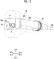
- Fig. 10 is a perspective view illustrating a configuration of the shield case 22.
- the shield case 22 is formed in a rectangular parallelepiped shape, and a long side 22A of the shield case 22 is accommodated in the connector exterior case 28 in a posture along the longitudinal axis 10a. Accordingly, a sufficient space is secured between the inner surface of the connector exterior case 28 and an outer surface of the shield case 22.
- the connector exterior case 28 is formed in a substantially cylindrical shape with a bulging front end.
- the connector exterior case 28 comprises the elliptical ring portion 46 that has an opening 27 in the front end.
- the elliptical ring portion 46 is configured to have a shape in plan view that is a race track shape (oval shape), in which a pair of parallel linear portions 46A and 46A, which face each other in the right-and-left direction, and a pair of curved portions 46B and 46B, which face each other in the up-and-down direction, are connected to each other.
- the connector exterior case 28 and the plug 26 are connected to each other by fitting the elliptical ring portion 30 of the plug 26 into the elliptical ring portion 46 of the connector exterior case 28.
- the linear portions 30A and 30A of the elliptical ring portion 30 and the linear portions 46A and 46A of the elliptical ring portion 46 are disposed to face each other, and the curved portions 30B and 30B of the elliptical ring portion 30 and the curved portions 46B and 46B of the elliptical ring portion 46 are disposed to face each other.
- an inner peripheral surface of the elliptical ring portion 46 comprises an annular groove 48 along the inner peripheral surface, and the O-ring 36 (see Fig. 5 ) on a plug 26 side is fitted to the groove 48. That is, the connector exterior case 28 and the plug 26 are connected to each other by fitting the elliptical ring portion 30 of the plug 26 into the elliptical ring portion 46 of the connector exterior case 28 and fitting the O-ring 36 to the groove 48 (see Fig. 3 ).
- the linear portions 46A and 46A of the elliptical ring portion 46 comprises a pair of through-holes 50 and 52 (only the through-holes 50 and 52 in a left surface of the elliptical ring portion 46 are illustrated) penetrating an outer peripheral surface and the inner peripheral surface of the elliptical ring portion 46, which are coaxial in the up-and-down direction.
- each of inner peripheral surfaces of the linear portions 46A and 46A comprises a semicircular groove 54, which connects the through-hole 50 and the through-hole 52 to each other, along the up-and-down direction.
- outer peripheral surfaces of the linear portions 30A and 30A of the elliptical ring portion 30 comprise semicircular grooves 56 and 56 (only the grooves 56 in a left surface of the elliptical ring portion 30 are illustrated) along the up-and-down direction, and the grooves 56 are disposed to face the grooves 54 in a state where the connector exterior case 28 and the plug 26 are connected to each other. Accordingly, as in a cross sectional view of main parts illustrated in Fig. 11 , a substantially cylindrical insertion passage 58 is formed along the up-and-down direction by a wall surface of the groove 54 and a wall surface of the groove 56.
- Fig. 8 illustrates a cylindrical pin 60 fitted from the through-hole 50 into the through-hole 52 via the insertion passage 58 (see Fig. 11 ).
- the pin 60 is fitted from the through-hole 50 into the through-hole 52 via the insertion passage 58 (see Fig. 11 ), an upper end part 60A of the pin 60 is fitted to an inner wall surface of the through-hole 50, a lower end part 60B of the pin 60 is fitted to an inner wall surface of the through-hole 52, and a portion of the pin 60 excluding the upper end part 60A and the lower end part 60B is fitted to the insertion passage 58.
- the plug 26 is prevented from coming off from the connector exterior case 28, and the linear portion 30A of the elliptical ring portion 30 is reinforced by the pin 60, causing a state where the deformation of the linear portion 30A is suppressed.
- the pin 60 is fastened to the elliptical ring portion 30 by a screw 62 (see Fig. 7 ) screwed from the lower end part 60B to the linear portion 30A of the elliptical ring portion 30. Accordingly, the pin 60 is prevented from falling off.
- the upper end part 60A and the lower end part 60B of the pin 60 are composed of slopes so as not to protrude from the outer peripheral surface of the linear portion 46A.
- the pin 60 is preferably made of a metal having high stiffness.
- the connector exterior case 28 comprises, in a rear end thereof, an opening portion 64 to which the universal cable 106 (see Fig. 3 ) is connected.
- an elastic O-ring 66 (see Fig. 10 ) is fitted to an outer peripheral surface of the universal cable 106, and the universal cable 106 is fitted into the opening portion 64 via the O-ring 66.
- the O-ring 66 is an example of a second sealing member that is arranged in a gap between an outer peripheral surface configuring an outer wall surface of the universal cable 106 and an inner peripheral surface configuring an inner wall surface of the opening portion 64 and is a component of the present invention.
- the O-ring 66 is also one of the plurality of sealing members that seal the inside of the exterior case 20, like the O-rings 36, 40, and 44.
- the insertion part 102, the grip portion 104, the switch disposed member 108, and the universal cable 106 are inserted into the outside from the opening 27 (see Fig. 7 ) of the connector exterior case 28 via the opening portion 64 (see Fig. 8 ), starting from the insertion part 102.
- the opening portion 64 of the connector exterior case 28 is configured in a size that allows the insertion part 102, the grip portion 104, the switch disposed member 108, and the universal cable 106 to be inserted therein. By configuring the opening portion 64 in such a size, it becomes easy to assemble the endoscope 100.
- the opening portion 64 has a size that allows the insertion even in a state where the operation switch 110 is disposed on the switch disposed member 108. That is, the inner diameter of the opening portion 64 may be set to be larger than the diameter of a circumscribed circle of the switch disposed member 108 including the operation switch 110 when viewed from a longitudinal axis direction of the universal cable 106.
- the inner case wall part 23 of the shield case 22 is disposed to face and be spaced apart from the side wall part 32D (see Fig. 5 ) toward the rear, and the power reception unit 24 is disposed on the inner case wall part 23. That is, in the connector device 10 of the embodiment, since the inner case wall part 23 is disposed at a position spaced apart from the side wall part 32D toward the rear, which is a position unlikely to be affected by a heat cycle of steam sterilization and the power reception unit 24 is disposed on the inner case wall part 23, the following effects can be obtained.
- the endoscope 100 can be stably operated.
- the endoscope 100 can be stably operated since the exterior case 20 has the side wall part 32D facing the power feed unit 216, the shield case 22 has the inner case wall part 23 disposed to face and be spaced apart from the side wall part 32D, and the power reception unit 24 is disposed on the inner case wall part 23.
- the inner case wall part 23 is made of a metal, the amount of deformation caused by being affected by the heat cycle is extremely smaller than the resin exterior case 20. Accordingly, since the position shift of the power reception unit 24 can be effectively suppressed, the operation of the endoscope 100 is more stabilized.
- the core of the secondary coil configuring the power reception unit 24 is composed of a highly heat-resistant sintered ferrite core and the power reception unit 24 is adhered to the shield case 22 using a highly heat-resistant thermosetting epoxy sheet, the highly heat-resistant power reception unit 24 that can withstand sterilization by the autoclave can be provided.
- the shield case 22 is disposed to be spaced apart from the inner surface of the plug 26 and the inner surface of the connector exterior case 28 as being disposed in the exterior case 20 via the pin 18.
- the temperature of the connector device 10 heated by the high-pressure steam sterilizer is gradually decreased by outside air.
- a temperature difference between the connector exterior case 28 and the shield case 22 is unlikely to occur in the process of decreasing the temperature after sterilization.
- moisture in the air inside the connector exterior case 28 adheres to an inner wall and the substrate of the shield case 22 and condensation occurs, causing a problem of adversely affecting the substrate. That is, condensation occurs also on an inner wall of the connector exterior case 28, but simultaneously with the condensation or without a time lag therebetween, condensation occurs on the inner wall and the substrate of the shield case 22.
- the outer surface of the shield case 22 is disposed to be spaced apart from the inner surface of the plug 26 and the inner surface of the connector exterior case 28.
- the connector exterior case 28 accommodates the shield case 22 in a posture in which the long side 22A of the shield case 22 is aligned with the longitudinal axis 10a, a sufficient space is secured between an inner surface of the exterior case 20 and the outer surface of the shield case 22. Therefore, condensation is unlikely to occur on the outer surface of the shield case 22 in the connector device 10 of the present embodiment. Accordingly, in the connector device 10 of the present embodiment, condensation on the substrate disposed inside the shield case 22 can be prevented.
- the outer surface of the shield case 22 is disposed to be spaced apart from the inner surface of the plug 26 and the inner surface of the connector exterior case 28, internal stress caused by a temperature difference between the connector exterior case 28 and the shield case 22 can be reduced. Accordingly, heat cycle resistance attributable to steam sterilization improves.
- time constant representing time required for the heat of the high-pressure steam sterilizer to be transmitted to an electrical component such as a substrate increases. Accordingly, thermal stress on the electrical component can be reduced.
- the plug 26 and the connector exterior case 28, which configure the exterior case 20 are preferably made of, for example, a polyphenylsulfone resin
- the light guide rod 12 and the pins 18 and 60 are preferably made of, for example, stainless steel
- the O-rings 36, 40, 44, and 66 are preferably made of, for example, highly heat-resistant fluororubber.
- the inner case wall part on which the power reception unit 24 is disposed is not limited to the shield case 22, that is, may be an inner case accommodated inside the exterior case 20, or may be, for example, an inner case that covers the shield case 22. In this case, it is preferable that the inner case is made of a metal.
- the plug 26 and the connector exterior case 28 which are examples of the exterior case, are made of a resin and the shield case 22, which is an example of the inner case, is made of a metal as a preferable aspect in the embodiment, without being limited thereto, the exterior case and the inner case may be made of other materials.
- the shapes of the elliptical ring portion 30 and the elliptical ring portion 46, which are connecting portions between the plug 26 and the connector exterior case 28, are a race track shape as a preferable aspect in the embodiment, but without being limited thereto, may be an oval shape (a shape that is not symmetrical with a line in a minor axis direction passing through an intersection between a major axis direction and the minor axis direction as a center line) such as a circle, an ellipse, and an egg shape in plan view insofar as the shape is a shape that can connect the plug 26 and the connector exterior case 28 to each other.
- an oval shape a shape that is not symmetrical with a line in a minor axis direction passing through an intersection between a major axis direction and the minor axis direction as a center line
- the shape is a shape that can connect the plug 26 and the connector exterior case 28 to each other.
- the core of the secondary coil configuring the power reception unit 24 is configured by a sintered ferrite core as a preferable aspect in the embodiment, the core may be made of other materials.
- the power reception unit 24 is adhered to the shield case 22 by a thermosetting adhesive material, but may be adhered to the shield case 22 by other adhesive materials.
Landscapes
- Physics & Mathematics (AREA)
- Optics & Photonics (AREA)
- Health & Medical Sciences (AREA)
- Life Sciences & Earth Sciences (AREA)
- Astronomy & Astrophysics (AREA)
- General Physics & Mathematics (AREA)
- Surgery (AREA)
- Engineering & Computer Science (AREA)
- Molecular Biology (AREA)
- Public Health (AREA)
- Biophysics (AREA)
- Pathology (AREA)
- Biomedical Technology (AREA)
- Heart & Thoracic Surgery (AREA)
- Radiology & Medical Imaging (AREA)
- Animal Behavior & Ethology (AREA)
- Medical Informatics (AREA)
- General Health & Medical Sciences (AREA)
- Nuclear Medicine, Radiotherapy & Molecular Imaging (AREA)
- Veterinary Medicine (AREA)
- Computer Networks & Wireless Communication (AREA)
- Endoscopes (AREA)
- Document Processing Apparatus (AREA)
Abstract
Description
- The present invention relates to a connector device for an endoscope, and particularly relates to a connector device for an endoscope connected to a processor device for an endoscope.
- A connector device for an endoscope (first connector) comprising a power reception coil is disclosed in
JP2016-67534A - In addition, the connector device of
JP2016-67534A - In the connector device comprising the power reception coil as in
JP2016-67534A - However, for example, in a case where the power reception coil is disposed in the exterior case of the connector device, there are the following problems. That is, it is necessary for the endoscope to be sterilized each time the endoscope is used. In this case, sterilization is performed using an autoclave in some cases, but the connector device at the time of sterilization is exposed to high-temperature and high-pressure (for example, 121°C and 2 atm) saturated steam for approximately 20 minutes. In a case where such sterilization is repeatedly performed, the shape of the exterior case of the connector device gradually deforms due to a heat cycle of the steam sterilization. Thus, the position of the power reception coil deviates from the initial position, and as a result, there are problems that the feeding efficiency decreases and the operation of the endoscope becomes unstable.
- The present invention is devised in view of such circumstances, and an object thereof is to provide a connector device for an endoscope that can stably operate an endoscope.
- According to an aspect of the present invention, in order to achieve the object of the present invention, there is provided a connector device for an endoscope that is attachably and detachably connected to a processor device. The connector device for an endoscope comprises a hollow exterior case, an inner case that is accommodated inside the exterior case, a holding body that is used for disposing the inner case inside the exterior case, and a power reception unit to which power is supplied from a power feed unit of the processor device in a contactless manner. The exterior case has a side wall part that faces the power feed unit of the processor device. The inner case has an inner case wall part that is disposed to face and be spaced apart from the side wall part. The power reception unit is disposed on the inner case wall part.
- In the aspect of the present invention, it is preferable that the power reception unit has a flat plate-shaped core and a coil that is spirally wound around the core, and the core is composed of a sintered ferrite core.
- In the aspect of the present invention, it is preferable that the power reception unit is adhered to the inner case wall part by a thermosetting adhesive material.
- In the aspect of the present invention, it is preferable that the holding body is a shaft-shaped member of which one end is fixed to the inner case wall part, a first lead-out hole, into which the shaft-shaped member is inserted and which leads the other end of the shaft-shaped member to an outside of the exterior case, is provided in the side wall part, and a first sealing member is arranged between an inner wall surface of the first lead-out hole and an outer wall surface of the shaft-shaped member.
- In the aspect of the present invention, it is preferable that the processor device has a positioning hole, into which the other end of the shaft-shaped member is inserted, in a surface facing the side wall part, and the other end of the shaft-shaped member is inserted into the positioning hole, and the power reception unit is in a state of being positioned at a position facing the power feed unit.
- In the aspect of the present invention, it is preferable that the first sealing member is an O-ring fitted to the outer wall surface of the shaft-shaped member.
- In the aspect of the present invention, it is preferable that the exterior case is made of a resin, and the inner case is made of a metal.
- In the aspect of the present invention, it is preferable that the inner case is a shield case for shielding an electronic component.
- In the aspect of the present invention, it is preferable that the exterior case has a cylindrical body, the inner case is formed in a rectangular parallelepiped shape, and the inner case is accommodated in the exterior case in a posture in which a long side of the inner case is aligned with an axis of the cylindrical body.
- In the aspect of the present invention, it is preferable that the exterior case has an opening portion to which a universal cable extending from an endoscope is connected, and a second sealing member is arranged between an inner wall surface of the opening portion and an outer wall surface of the universal cable.
- In the aspect of the present invention, it is preferable that the second sealing member is an O-ring fitted to the outer wall surface of the universal cable.
- In the aspect of the present invention, it is preferable that the opening portion of the exterior case is formed in a size that allows the endoscope, the universal cable, and a switch disposed member provided at the universal cable to be inserted therein.
- In the aspect of the present invention, it is preferable that the connector device for an endoscope further comprises a light guide rod of which one end is disposed inside the exterior case, a second lead-out hole, into which the light guide rod is inserted and which leads the other end of the light guide rod to an outside of the exterior case, is provided in the side wall part, and a third sealing member is arranged between an inner wall surface of the second lead-out hole and an outer wall surface of the light guide rod.
- In the aspect of the present invention, it is preferable that the third sealing member is an O-ring fitted to the outer wall surface of the light guide rod.
- With the present invention, the endoscope can be stably operated.
-
-
Fig. 1 is a schematic configuration view of a surgical system. -
Fig. 2 is a front view of a tip part of an insertion part. -
Fig. 3 is an external perspective view of a connector device. -
Fig. 4 is a perspective view of a plug configuring an exterior case. -
Fig. 5 is a perspective view of the plug viewed from the front toward the rear. -
Fig. 6 is a perspective view of the plug viewed from the rear toward the front. -
Fig. 7 is a perspective view of a connector exterior case configuring the exterior case viewed from the front toward the rear. -
Fig. 8 is a perspective view of the connector exterior case viewed from the rear toward the front. -
Fig. 9 is a perspective view of the connector exterior case including a light guide rod viewed from the front toward the rear. -
Fig. 10 is a perspective view illustrating a configuration of a shield case. -
Fig. 11 is an enlarged cross sectional view of main parts, which illustrates an insertion passage into which a pin is inserted. - Hereinafter, a connector device for an endoscope according to an embodiment of the present invention will be described with reference to the accompanying drawings.
-
Fig. 1 is a schematic configuration view of an endoscope system 1. The endoscope system 1 comprises anendoscope 100 and a processor device for anendoscope 200. - The
endoscope 100 is a rigid endoscope, such as a laparoscope, and comprises an elongatedrigid insertion part 102 that is inserted into a body cavity, an L-shaped grip portion 104 continuously connected to a proximal end part of theinsertion part 102, a flexibleuniversal cable 106 of which a proximal end part is connected to theinsertion part 102 via thegrip portion 104, and a switch disposedmember 108 provided in a middle portion of theuniversal cable 106. - A
connector device 10 according to the embodiment is provided at a tip part of theuniversal cable 106, and theendoscope 100 is attachably and detachably connected to aprocessor side connector 210 of the processor device for anendoscope 200 via theconnector device 10.Fig. 1 illustrates theconnector device 10 in an exaggerated manner as compared with theendoscope 100. - The processor device for an
endoscope 200 comprises animage processing unit 206, which includes a light source unit 202, and an imagesignal reception unit 204. In addition, amonitor 208 that displays an image which is image-processed by theimage processing unit 206 is connected to the processor device for anendoscope 200. - The endoscope system 1 of the present example has a configuration that transmits power, optical signals, and the like in a contactless manner between the
endoscope 100 and the processor device for anendoscope 200 via a connector part composed of theconnector device 10 and theprocessor side connector 210. In addition, as anoperation switch 110 disposed on the switch disposedmember 108 described above, for example, an image changeover switch that switches an image to be displayed on themonitor 208 between a normal captured image and a special light image (for example, a white light (WL) image, a blue laser imaging (BLI) image, a linked color imaging (LCI) image, or a hypoxia imaging image) can be applied. In addition, without being limited to the image changeover switch, an image immobilizing switch, an imaging switch, a zoom switch comprising a telephoto and wide-angle button, a insertion part tip part washing switch, a light amount adjusting switch, a sensitivity adjusting switch, or the like can also be applied. -
Fig. 2 is a front view of a tip part of theinsertion part 102. In addition,Fig. 1 illustrates an enlarged cross section of main parts at the tip part of theinsertion part 102. - As illustrated in
Figs. 1 and2 , anobservation part 114 is provided on adistal end surface 102A of theinsertion part 102. Theobservation part 114 comprises anobservation window 116, threelight emission ends 118A that are tip parts of alight guide 118, which is disposed around theobservation window 116, an image pick-up lens group 120 and aprism 122 that are disposed behind theobservation window 116, and a solid-state imaging element 124. As the solid-state imaging element 124, a charge coupled device (CCD) image sensor or a complementary metal oxide semiconductor (CMOS) image sensor can be applied. - A proximal end part of the
light guide 118 is inserted into theinsertion part 102, thegrip portion 104, and theuniversal cable 106, and is disposed to be inserted in a cylindricallight guide rod 12 of theconnector device 10. By connecting thelight guide rod 12 to aconnection hole 212 of theprocessor side connector 210, alight incident end 118B of thelight guide 118 is connected to the light source unit 202 of the processor device for anendoscope 200. Accordingly, illumination light from the light source unit 202 is transmitted via thelight guide 118, and is radiated to the front of theinsertion part 102 from the three light emission ends 118A of thelight guide 118. - On the other hand, subject light picked up from the
observation window 116 is formed as an image on an imaging surface of the solid-state imaging element 124 via the image pick-uplens group 120 and theprism 122, and is converted to an image pick-up signal by the solid-state imaging element 124. A tip part of asignal line 126 is connected to the solid-state imaging element 124 via a base substrate (not illustrated). A proximal end part of thesignal line 126 is inserted into theinsertion part 102, thegrip portion 104, and theuniversal cable 106, and is connected to an imagesignal transmission unit 14 accommodated in anexterior case 20 of theconnector device 10. The image pick-up signal is converted to an optical signal by the imagesignal transmission unit 14, and the optical signal is transmitted to afiber cable 16 accommodated in theexterior case 20. - A
light emission end 16A of thefiber cable 16 is disposed to be inserted in acylindrical pin 18 of theconnector device 10. By connecting thepin 18 to aconnection hole 214 of theprocessor side connector 210, the optical signal is optically transmitted to the imagesignal reception unit 204 of the processor device for anendoscope 200 in a contactless manner. The optical signal optically transmitted to the imagesignal reception unit 204 is image-processed by theimage processing unit 206 and is displayed on themonitor 208 as a subject image. - The
pin 18 is an example of a shaft-shaped member, which is a component of the present invention. A proximal end part of thepin 18 is fixed to ametal shield case 22 accommodated inside theexterior case 20, and theshield case 22 is positioned at theprocessor side connector 210 by connecting thepin 18 to theconnection hole 214. In addition, an electronic component such as a substrate configuring the imagesignal transmission unit 14 is mounted inside theshield case 22. - The
connector device 10 is provided with apower reception unit 24 that receives power in a contactless manner, and theprocessor side connector 210 is provided with apower feed unit 216 that feeds power in a contactless manner. In the endoscope system 1 of the present example, a contactless power supply unit is composed of thepower feed unit 216 and thepower reception unit 24, and power necessary for driving an electronic component on anendoscope 100 side is supplied by the power supply unit from the processor device for anendoscope 200 to theconnector device 10. As will be described later, thepower reception unit 24 is not fixed to theexterior case 20, and is fixed to theshield case 22 like thepin 18. - In a case where the
connector device 10 is connected to theprocessor side connector 210 via thelight guide rod 12 and thepin 18, thepower feed unit 216 and thepower reception unit 24 are disposed near to face each other at a distance allowing electromagnetic coupling, and are in a state where power feeding from thepower feed unit 216 to thepower reception unit 24 is possible in a contactless manner. Thepower feed unit 216 is connected to an external commercial power source, and in a case where power is supplied from the commercial power source to thepower feed unit 216, power is fed in a contactless manner from thepower feed unit 216 to thepower reception unit 24. - A primary coil (also referred to as a power feeding coil) connected to the commercial power source can be given as an example of the
power feed unit 216, and a secondary coil (also referred to as a power reception coil) electromagnetically coupled to the primary coil can be given as an example of thepower reception unit 24. - A structure in which a coil is spirally wound around a surface of a flat plate-shaped core can be given as an example of the structures of the primary coil and the secondary coil. In this case, a core of the secondary coil configuring the
power reception unit 24 is preferably, for example, a highly heat-resistant sintered ferrite core. Accordingly, the highly heat-resistantpower reception unit 24 that can withstand the heat of an autoclave can be configured. In addition, thepower reception unit 24 is fixed to theshield case 22 as will be described later. However, in this case, it is preferable to adhere thepower reception unit 24 to theshield case 22, for example, using a thermosetting adhesive material such as a highly heat-resistant thermosetting epoxy sheet. Accordingly, the highly heat-resistantpower reception unit 24 can be configured. - The power supply unit in which the
power feed unit 216 is configured by the primary coil and thepower reception unit 24 is configured by the secondary coil is given as an example of the contactless power supply unit in the embodiment, but without being limited thereto, may be a power supply unit that can feed and receive power in a contactless manner. Since an endoscope that feeds power using the primary coil and the secondary coil is known inJP2016-67534A - Next, a structure of the
connector device 10 will be described.Fig. 3 is an overall perspective view illustrating the appearance of theconnector device 10. - As illustrated in
Fig. 3 , theexterior case 20 of theconnector device 10 has alongitudinal axis 10a parallel to an axial direction of the cylindricallight guide rod 12 and thepin 18. In the following description, a position and a direction of a space where theconnector device 10 is disposed will be described using the following terms. An X(+) direction and an X(-) direction along thelongitudinal axis 10a are the "front" and the "rear" respectively, a Y(+) direction and a Y(-) direction orthogonal to the X-direction are the "left" and the "right" respectively, and a Z(+) direction and a Z(-) direction orthogonal to the XY-directions are the "up" and the "down" respectively. - The
connector device 10 has the highly heat-resistant and chemical-resistantresin exterior case 20, the metallight guide rod 12, themetal pin 18, and the metal shield case 22 (seeFig. 1 ). -
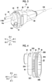
Fig. 4 is a perspective view of aplug 26 configuring theexterior case 20.Fig. 5 is a perspective view of theplug 26 viewed from the front toward the rear.Fig. 6 is a perspective view of theplug 26 viewed from the rear toward the front. - In addition,
Fig. 7 is a perspective view of aconnector exterior case 28 configuring theexterior case 20 viewed from the front toward the rear.Fig. 8 is a perspective view of theconnector exterior case 28 viewed from the rear toward the front. - Referring back to
Fig. 3 , theexterior case 20 is formed in a hollow shape by connecting theplug 26 illustrated inFigs. 4 to 6 to theconnector exterior case 28 illustrated inFigs. 7 and8 . - As illustrated in
Figs. 4 to 6 , theplug 26 comprises anelliptical ring portion 30 that has anopening 29 in a rear end, amount portion 32 that protrudes from theelliptical ring portion 30 toward the front, and acylindrical portion 34 that protrudes from themount portion 32 toward the front. - As illustrated in
Fig. 6 , theelliptical ring portion 30 is configured to have a shape in plan view that is a race track shape (oval shape), in which a pair of parallellinear portions curved portions ring 36, which is a sealing member, is fitted to an outer peripheral surface of theelliptical ring portion 30. The O-ring 36 is also one of a plurality of sealing members that seal the inside of theexterior case 20, as will be described later. - As illustrated in
Fig. 5 , themount portion 32 is configured to have a shape in plan view that is a substantially semi-elliptical shape, in which a pair of parallellinear portions curved portion 30B and a linear portion 30C, which face each other in the up-and-down direction, are connected to each other. - The
cylindrical portion 34 is provided on an upper part of aside wall part 32D of themount portion 32 and comprises, in a center part thereof, a lead-out hole 38 that leads the light guide rod 12 (seeFig. 3 ) to the outside. The lead-out hole 38 is an example of a second lead-out hole, which is a component of the present invention. In addition, theside wall part 32D is an example of a side wall part, which is a component of the present invention. In a case where theconnector device 10 is connected to the processor device for anendoscope 200, theside wall part 32D is disposed to face the power feed unit 216 (seeFig. 1 ) of the processor device for anendoscope 200. -
Fig. 9 is a perspective view of theconnector exterior case 28 viewed from the front toward the rear, and illustrates thelight guide rod 12 and theshield case 22. As illustrated inFig. 9 , thelight guide rod 12 has a proximal end part disposed inside theexterior case 20, and is fixed to a substantiallysemicircular bracket 13. As thebracket 13 is fixed to an inner peripheral surface of theplug 26 illustrated inFigs. 4 to 6 , thelight guide rod 12 is supported by theplug 26. - In addition, as illustrated in
Fig. 9 , an elastic O-ring 40 is fitted to an outer peripheral surface of thelight guide rod 12, and thelight guide rod 12 is fitted into the lead-out hole 38 (seeFig. 5 ) via the O-ring 40. The O-ring 40 is an example of a third sealing member that is arranged in a gap between an outer peripheral surface configuring an outer wall surface of thelight guide rod 12 and an inner peripheral surface configuring an inner wall surface of the lead-out hole 38 and is a component of the present invention. The O-ring 40 is also one of the plurality of sealing members that seal the inside of theexterior case 20, like the O-ring 36. - Referring back to
Fig. 5 , theside wall part 32D of themount portion 32 comprises a lead-out hole 42 that leads the pin 18 (seeFig. 3 ) to the outside. The lead-out hole 42 is an example of a first lead-out hole, which is a component of the present invention. - As illustrated in
Fig. 9 , one end of thepin 18 is fixed to an innercase wall part 23, which is a front surface of theshield case 22, and the other end of thepin 18 is disposed to face the front. In addition, an elastic O-ring 44 is fitted to an outer peripheral surface of thepin 18, and thepin 18 is fitted into the lead-out hole 42 (seeFig. 5 ) via the O-ring 44. The O-ring 44 is an example of a first sealing member that is arranged in a gap between an outer peripheral surface configuring an outer wall surface of thepin 18 and an inner peripheral surface configuring an inner wall surface of the lead-out hole 42 and is a component of the present invention. The O-ring 44 is also one of the plurality of sealing members that seal the inside of theexterior case 20, like the O-rings - In addition, by fitting the
pin 18 into the lead-out hole 42 via the O-ring 44, the shield case 22 (seeFig. 1 ) is disposed inside theexterior case 20 by thepin 18. That is, theshield case 22 is disposed to be spaced apart from the inner surfaces of theplug 26 and theconnector exterior case 28 by thepin 18. -
Fig. 10 is a perspective view illustrating a configuration of theshield case 22. As illustrated inFig. 10 , theshield case 22 is formed in a rectangular parallelepiped shape, and along side 22A of theshield case 22 is accommodated in theconnector exterior case 28 in a posture along thelongitudinal axis 10a. Accordingly, a sufficient space is secured between the inner surface of theconnector exterior case 28 and an outer surface of theshield case 22. - As illustrated in
Figs. 7 and8 , theconnector exterior case 28 is formed in a substantially cylindrical shape with a bulging front end. Theconnector exterior case 28 comprises theelliptical ring portion 46 that has anopening 27 in the front end. Theelliptical ring portion 46 is configured to have a shape in plan view that is a race track shape (oval shape), in which a pair of parallellinear portions curved portions - The
connector exterior case 28 and the plug 26 (seeFig. 6 ) are connected to each other by fitting theelliptical ring portion 30 of theplug 26 into theelliptical ring portion 46 of theconnector exterior case 28. In this connected state, thelinear portions elliptical ring portion 30 and thelinear portions elliptical ring portion 46 are disposed to face each other, and thecurved portions elliptical ring portion 30 and thecurved portions elliptical ring portion 46 are disposed to face each other. Then, as illustrated inFig. 7 , an inner peripheral surface of theelliptical ring portion 46 comprises anannular groove 48 along the inner peripheral surface, and the O-ring 36 (seeFig. 5 ) on aplug 26 side is fitted to thegroove 48. That is, theconnector exterior case 28 and theplug 26 are connected to each other by fitting theelliptical ring portion 30 of theplug 26 into theelliptical ring portion 46 of theconnector exterior case 28 and fitting the O-ring 36 to the groove 48 (seeFig. 3 ). - On the other hand, as illustrated in
Fig. 8 , thelinear portions elliptical ring portion 46 comprises a pair of through-holes 50 and 52 (only the through-holes elliptical ring portion 46 are illustrated) penetrating an outer peripheral surface and the inner peripheral surface of theelliptical ring portion 46, which are coaxial in the up-and-down direction. In addition, as illustrated inFig. 7 , each of inner peripheral surfaces of thelinear portions semicircular groove 54, which connects the through-hole 50 and the through-hole 52 to each other, along the up-and-down direction. Further, as illustrated inFigs. 4 and5 , outer peripheral surfaces of thelinear portions elliptical ring portion 30 comprisesemicircular grooves 56 and 56 (only thegrooves 56 in a left surface of theelliptical ring portion 30 are illustrated) along the up-and-down direction, and thegrooves 56 are disposed to face thegrooves 54 in a state where theconnector exterior case 28 and theplug 26 are connected to each other. Accordingly, as in a cross sectional view of main parts illustrated inFig. 11 , a substantiallycylindrical insertion passage 58 is formed along the up-and-down direction by a wall surface of thegroove 54 and a wall surface of thegroove 56. -
Fig. 8 illustrates acylindrical pin 60 fitted from the through-hole 50 into the through-hole 52 via the insertion passage 58 (seeFig. 11 ). Thepin 60 is fitted from the through-hole 50 into the through-hole 52 via the insertion passage 58 (seeFig. 11 ), anupper end part 60A of thepin 60 is fitted to an inner wall surface of the through-hole 50, alower end part 60B of thepin 60 is fitted to an inner wall surface of the through-hole 52, and a portion of thepin 60 excluding theupper end part 60A and thelower end part 60B is fitted to theinsertion passage 58. Accordingly, theplug 26 is prevented from coming off from theconnector exterior case 28, and thelinear portion 30A of theelliptical ring portion 30 is reinforced by thepin 60, causing a state where the deformation of thelinear portion 30A is suppressed. In addition, thepin 60 is fastened to theelliptical ring portion 30 by a screw 62 (seeFig. 7 ) screwed from thelower end part 60B to thelinear portion 30A of theelliptical ring portion 30. Accordingly, thepin 60 is prevented from falling off. Further, theupper end part 60A and thelower end part 60B of thepin 60 are composed of slopes so as not to protrude from the outer peripheral surface of thelinear portion 46A. Thepin 60 is preferably made of a metal having high stiffness. - As illustrated in
Fig. 8 , theconnector exterior case 28 comprises, in a rear end thereof, an openingportion 64 to which the universal cable 106 (seeFig. 3 ) is connected. In addition, an elastic O-ring 66 (seeFig. 10 ) is fitted to an outer peripheral surface of theuniversal cable 106, and theuniversal cable 106 is fitted into the openingportion 64 via the O-ring 66. The O-ring 66 is an example of a second sealing member that is arranged in a gap between an outer peripheral surface configuring an outer wall surface of theuniversal cable 106 and an inner peripheral surface configuring an inner wall surface of the openingportion 64 and is a component of the present invention. The O-ring 66 is also one of the plurality of sealing members that seal the inside of theexterior case 20, like the O-rings - When assembling the
endoscope 100 illustrated inFig. 1 , theinsertion part 102, thegrip portion 104, the switch disposedmember 108, and theuniversal cable 106 are inserted into the outside from the opening 27 (seeFig. 7 ) of theconnector exterior case 28 via the opening portion 64 (seeFig. 8 ), starting from theinsertion part 102. For this reason, the openingportion 64 of theconnector exterior case 28 is configured in a size that allows theinsertion part 102, thegrip portion 104, the switch disposedmember 108, and theuniversal cable 106 to be inserted therein. By configuring the openingportion 64 in such a size, it becomes easy to assemble theendoscope 100. In addition, even when disassembling theendoscope 100, it becomes easy to disassemble the endoscope. It is more preferable that the openingportion 64 has a size that allows the insertion even in a state where theoperation switch 110 is disposed on the switch disposedmember 108. That is, the inner diameter of the openingportion 64 may be set to be larger than the diameter of a circumscribed circle of the switch disposedmember 108 including theoperation switch 110 when viewed from a longitudinal axis direction of theuniversal cable 106. - However, in the
connector device 10 of the embodiment, as illustrated inFigs. 9 and10 , inside theexterior case 20, the innercase wall part 23 of theshield case 22 is disposed to face and be spaced apart from theside wall part 32D (seeFig. 5 ) toward the rear, and thepower reception unit 24 is disposed on the innercase wall part 23. That is, in theconnector device 10 of the embodiment, since the innercase wall part 23 is disposed at a position spaced apart from theside wall part 32D toward the rear, which is a position unlikely to be affected by a heat cycle of steam sterilization and thepower reception unit 24 is disposed on the innercase wall part 23, the following effects can be obtained. - For example, even in a case where the shape of the exterior case 20 (in particular, the plug 26) is deformed by the effect of the heat cycle of steam sterilization, a position shift of the
power reception unit 24 can be suppressed since thepower reception unit 24 is disposed on the innercase wall part 23 which is unlikely to be affected by the heat cycle. Accordingly, since a decrease in feeding efficiency attributable to the position shift of thepower reception unit 24 can be suppressed, theendoscope 100 can be stably operated. - As described above, in the
connector device 10 of the embodiment, theendoscope 100 can be stably operated since theexterior case 20 has theside wall part 32D facing thepower feed unit 216, theshield case 22 has the innercase wall part 23 disposed to face and be spaced apart from theside wall part 32D, and thepower reception unit 24 is disposed on the innercase wall part 23. - In addition, since the inner
case wall part 23 is made of a metal, the amount of deformation caused by being affected by the heat cycle is extremely smaller than theresin exterior case 20. Accordingly, since the position shift of thepower reception unit 24 can be effectively suppressed, the operation of theendoscope 100 is more stabilized. - In addition, since the core of the secondary coil configuring the
power reception unit 24 is composed of a highly heat-resistant sintered ferrite core and thepower reception unit 24 is adhered to theshield case 22 using a highly heat-resistant thermosetting epoxy sheet, the highly heat-resistantpower reception unit 24 that can withstand sterilization by the autoclave can be provided. - In addition, by fixing the
power reception unit 24 to ashield case 22 side, workability of arranging a lead wire from thepower reception unit 24 to theshield case 22 side and workability of connecting the lead wire to a substrate of theshield case 22 improve, and disassembling work of theshield case 22 and theplug 26 also becomes easy. - In addition, in the
connector device 10 of the embodiment, theshield case 22 is disposed to be spaced apart from the inner surface of theplug 26 and the inner surface of theconnector exterior case 28 as being disposed in theexterior case 20 via thepin 18. With this configuration, theconnector device 10 of the embodiment can obtain the following effects. - That is, in a case where the
endoscope 100 comprising theconnector device 10 is taken out from a high-pressure steam sterilizer, the temperature of theconnector device 10 heated by the high-pressure steam sterilizer is gradually decreased by outside air. Herein, for example, in a case where a configuration in which theshield case 22 is in contact with theexterior case 20, in particular, the inner surface of theconnector exterior case 28 is adopted, a temperature difference between theconnector exterior case 28 and theshield case 22 is unlikely to occur in the process of decreasing the temperature after sterilization. Thus, moisture in the air inside theconnector exterior case 28 adheres to an inner wall and the substrate of theshield case 22 and condensation occurs, causing a problem of adversely affecting the substrate. That is, condensation occurs also on an inner wall of theconnector exterior case 28, but simultaneously with the condensation or without a time lag therebetween, condensation occurs on the inner wall and the substrate of theshield case 22. - On the contrary, in the
connector device 10 of the embodiment, as theshield case 22 is held by theexterior case 20 via thepin 18, the outer surface of theshield case 22 is disposed to be spaced apart from the inner surface of theplug 26 and the inner surface of theconnector exterior case 28. In addition, in theconnector device 10 of the embodiment, as theconnector exterior case 28 accommodates theshield case 22 in a posture in which thelong side 22A of theshield case 22 is aligned with thelongitudinal axis 10a, a sufficient space is secured between an inner surface of theexterior case 20 and the outer surface of theshield case 22. Therefore, condensation is unlikely to occur on the outer surface of theshield case 22 in theconnector device 10 of the present embodiment. Accordingly, in theconnector device 10 of the present embodiment, condensation on the substrate disposed inside theshield case 22 can be prevented. - In addition, in the
connector device 10 of the embodiment, since the outer surface of theshield case 22 is disposed to be spaced apart from the inner surface of theplug 26 and the inner surface of theconnector exterior case 28, internal stress caused by a temperature difference between theconnector exterior case 28 and theshield case 22 can be reduced. Accordingly, heat cycle resistance attributable to steam sterilization improves. - In addition, in the
connector device 10 of the present embodiment, since a sufficient space is secured between the inner surface of theexterior case 20 and the outer surface of theshield case 22, time constant (relaxation time) representing time required for the heat of the high-pressure steam sterilizer to be transmitted to an electrical component such as a substrate increases. Accordingly, thermal stress on the electrical component can be reduced. - In addition, in the
connector device 10 of the embodiment, theplug 26 and theconnector exterior case 28, which configure theexterior case 20, are preferably made of, for example, a polyphenylsulfone resin, thelight guide rod 12 and thepins rings - In addition, although an aspect in which the
power reception unit 24 is disposed on the innercase wall part 23 of theshield case 22 in theconnector device 10 of the embodiment is given as an example, the inner case wall part on which thepower reception unit 24 is disposed is not limited to theshield case 22, that is, may be an inner case accommodated inside theexterior case 20, or may be, for example, an inner case that covers theshield case 22. In this case, it is preferable that the inner case is made of a metal. - In addition, although the
plug 26 and theconnector exterior case 28, which are examples of the exterior case, are made of a resin and theshield case 22, which is an example of the inner case, is made of a metal as a preferable aspect in the embodiment, without being limited thereto, the exterior case and the inner case may be made of other materials. - In addition, the shapes of the
elliptical ring portion 30 and theelliptical ring portion 46, which are connecting portions between theplug 26 and theconnector exterior case 28, are a race track shape as a preferable aspect in the embodiment, but without being limited thereto, may be an oval shape (a shape that is not symmetrical with a line in a minor axis direction passing through an intersection between a major axis direction and the minor axis direction as a center line) such as a circle, an ellipse, and an egg shape in plan view insofar as the shape is a shape that can connect theplug 26 and theconnector exterior case 28 to each other. - In addition, although the core of the secondary coil configuring the
power reception unit 24 is configured by a sintered ferrite core as a preferable aspect in the embodiment, the core may be made of other materials. In addition, thepower reception unit 24 is adhered to theshield case 22 by a thermosetting adhesive material, but may be adhered to theshield case 22 by other adhesive materials. - Although the present invention has been described hereinbefore, the present invention is not limited to the examples, and it is evident that various improvements and modifications may be made without departing from the gist of the present invention.
-
- 1: endoscope system
- 10: connector device
- 10a: longitudinal axis
- 12: light guide rod
- 13: bracket
- 14: image signal transmission unit
- 16: fiber cable
- 16A: light emission end
- 18: pin
- 20: exterior case
- 22: shield case
- 22A: long side
- 23: inner case wall part
- 24: power reception unit
- 26: plug
- 28: connector exterior case
- 30: elliptical ring portion
- 30A: linear portion
- 30B: curved portion
- 32: mount portion
- 32A: linear portion
- 32B: curved portion
- 32C: linear portion
- 32D: side wall part
- 34: cylindrical portion
- 36: O-ring
- 38: lead-out hole
- 40: O-ring
- 42: lead-out hole
- 44: O-ring
- 46: elliptical ring portion
- 46A: linear portion
- 46B: curved portion
- 48: groove
- 50: through-hole
- 52: through-hole
- 54: groove
- 56: groove
- 58: insertion passage
- 60: pin
- 60A: upper end part
- 60B: lower end part
- 62: screw
- 64: opening portion
- 66: O-ring
- 100: endoscope
- 102: insertion part
- 102A: distal end surface
- 104: grip portion
- 106: universal cable
- 108: switch disposed member
- 110: operation switch
- 114: observation part
- 116: observation window
- 118: light guide
- 118A: light emission end
- 118B: light incident end
- 120: image pick-up lens group
- 122: prism
- 124: solid-state imaging element
- 126: signal line
- 200: processor device for an endoscope
- 202: light source unit
- 204: image signal reception unit
- 206: image processing unit
- 208: monitor
- 210: processor side connector
- 212: connection hole
- 214: connection hole
- 216: power feed unit
Claims (14)
- A connector device for an endoscope that is attachably and detachably connected to a processor device, the connector device comprising:a hollow exterior case;an inner case that is accommodated inside the exterior case;a holding body that is used for disposing the inner case inside the exterior case; anda power reception unit to which power is supplied from a power feed unit of the processor device in a contactless manner,wherein the exterior case has a side wall part that faces the power feed unit of the processor device,the inner case has an inner case wall part that is disposed to face and be spaced apart from the side wall part, andthe power reception unit is disposed on the inner case wall part.
- The connector device for an endoscope according to claim 1,wherein the power reception unit has a flat plate-shaped core and a coil that is spirally wound around the core, andthe core is composed of a sintered ferrite core.
- The connector device for an endoscope according to claim 1 or 2,
wherein the power reception unit is adhered to the inner case wall part by a thermosetting adhesive material. - The connector device for an endoscope according to any one of claims 1 to 3,wherein the holding body is a shaft-shaped member of which one end is fixed to the inner case wall part,a first lead-out hole, into which the shaft-shaped member is inserted and which leads the other end of the shaft-shaped member to an outside of the exterior case, is provided in the side wall part, anda first sealing member is arranged between an inner wall surface of the first lead-out hole and an outer wall surface of the shaft-shaped member.
- The connector device for an endoscope according to claim 4,wherein the processor device has a positioning hole, into which the other end of the shaft-shaped member is inserted, in a surface facing the side wall part, andthe other end of the shaft-shaped member is inserted into the positioning hole, and the power reception unit is in a state of being positioned at a position facing the power feed unit.
- The connector device for an endoscope according to claim 4 or 5,
wherein the first sealing member is an O-ring fitted to the outer wall surface of the shaft-shaped member. - The connector device for an endoscope according to any one of claims 1 to 6,wherein the exterior case is made of a resin, andthe inner case is made of a metal.
- The connector device for an endoscope according to any one of claims 1 to 7,
wherein the inner case is a shield case for shielding an electronic component. - The connector device for an endoscope according to any one of claims 1 to 8,wherein the exterior case has a cylindrical body,the inner case is formed in a rectangular parallelepiped shape, andthe inner case is accommodated in the exterior case in a posture in which a long side of the inner case is aligned with an axis of the cylindrical body.
- The connector device for an endoscope according to any one of claims 1 to 9,the exterior case has an opening portion to which a universal cable extending from an endoscope is connected, anda second sealing member is arranged between an inner wall surface of the opening portion and an outer wall surface of the universal cable.
- The connector device for an endoscope according to claim 10,
wherein the second sealing member is an O-ring fitted to the outer wall surface of the universal cable. - The connector device for an endoscope according to claim 10 or 11,
wherein the opening portion of the exterior case is formed in a size that allows the endoscope, the universal cable, and a switch disposed member provided at the universal cable to be inserted therein. - The connector device for an endoscope according to any one of claims 1 to 12, further comprising:a light guide rod of which one end is disposed inside the exterior case,wherein a second lead-out hole, into which the light guide rod is inserted and which leads the other end of the light guide rod to an outside of the exterior case, is provided in the side wall part, anda third sealing member is arranged between an inner wall surface of the second lead-out hole and an outer wall surface of the light guide rod.
- The connector device for an endoscope according to claim 13,
wherein the third sealing member is an O-ring fitted to the outer wall surface of the light guide rod.
Applications Claiming Priority (2)
| Application Number | Priority Date | Filing Date | Title |
|---|---|---|---|
| JP2019050668 | 2019-03-19 | ||
| PCT/JP2020/011161 WO2020189564A1 (en) | 2019-03-19 | 2020-03-13 | Endoscope connector device |
Publications (3)
| Publication Number | Publication Date |
|---|---|
| EP3943998A1 true EP3943998A1 (en) | 2022-01-26 |
| EP3943998A4 EP3943998A4 (en) | 2022-05-11 |
| EP3943998B1 EP3943998B1 (en) | 2025-05-28 |
Family
ID=72519333
Family Applications (1)
| Application Number | Title | Priority Date | Filing Date |
|---|---|---|---|
| EP20773654.7A Active EP3943998B1 (en) | 2019-03-19 | 2020-03-13 | Endoscope connector device |
Country Status (5)
| Country | Link |
|---|---|
| US (1) | US12105276B2 (en) |
| EP (1) | EP3943998B1 (en) |
| JP (1) | JP7078798B2 (en) |
| CN (1) | CN113544566B (en) |
| WO (1) | WO2020189564A1 (en) |
Families Citing this family (2)
| Publication number | Priority date | Publication date | Assignee | Title |
|---|---|---|---|---|
| US11867897B2 (en) * | 2021-07-06 | 2024-01-09 | Evident Corporation | Insertion assisting instrument and extraction method of insertion portion of endoscope |
| CN117064310B (en) * | 2023-10-12 | 2024-02-20 | 深圳英美达医疗技术有限公司 | Light guide connector and endoscope |
Family Cites Families (29)
| Publication number | Priority date | Publication date | Assignee | Title |
|---|---|---|---|---|
| JPH07191268A (en) * | 1993-12-27 | 1995-07-28 | Olympus Optical Co Ltd | Light source device for endoscope |
| JP3621761B2 (en) * | 1995-08-30 | 2005-02-16 | フジノン株式会社 | Connector device for electronic endoscope |
| JP4073070B2 (en) * | 1998-01-13 | 2008-04-09 | オリンパス株式会社 | Endoscope device for TIG welding |
| JP3684122B2 (en) * | 1999-11-29 | 2005-08-17 | オリンパス株式会社 | Electronic endoscope |
| JP4914540B2 (en) * | 2001-05-25 | 2012-04-11 | オリンパス株式会社 | Eddy current flaw detector |
| CN1542536A (en) * | 2003-11-07 | 2004-11-03 | 中国科学院上海光学精密机械研究所 | Head-mounted illumination camera system based on light-emitting diodes |
| JP4009613B2 (en) | 2004-04-08 | 2007-11-21 | オリンパス株式会社 | Endoscope |
| JP2006320381A (en) * | 2005-05-17 | 2006-11-30 | Media Technology:Kk | Electronic endoscope device |
| JP2009082504A (en) * | 2007-09-28 | 2009-04-23 | Fujifilm Corp | Imaging apparatus and endoscope provided with the imaging apparatus |
| JP2010069231A (en) * | 2008-09-22 | 2010-04-02 | Fujifilm Corp | Imaging apparatus and endoscope |
| US8696657B2 (en) * | 2008-12-22 | 2014-04-15 | Olympus Medical Systems Corp. | Treatment tool |
| JP5361511B2 (en) | 2009-04-21 | 2013-12-04 | オリンパス株式会社 | Endoscope system |
| JP5298259B1 (en) | 2011-09-22 | 2013-09-25 | オリンパスメディカルシステムズ株式会社 | Endoscope |
| EP2820691B1 (en) | 2012-08-29 | 2016-04-06 | Gyrus Acmi Inc. | Battery pack attached to a cable |
| US9629518B2 (en) * | 2012-12-27 | 2017-04-25 | Arthrex, Inc. | Contactless camera connection system |
| JP5978238B2 (en) | 2014-03-27 | 2016-08-24 | 富士フイルム株式会社 | Electronic endoscope and electronic endoscope apparatus |
| US11234581B2 (en) * | 2014-05-02 | 2022-02-01 | Endochoice, Inc. | Elevator for directing medical tool |
| JP2016064050A (en) * | 2014-09-25 | 2016-04-28 | Hoya株式会社 | Internal pressure adjustment device of endoscope |
| JP6106142B2 (en) * | 2014-09-29 | 2017-03-29 | 富士フイルム株式会社 | Endoscope system, endoscope, and connector for endoscope |
| JP6215806B2 (en) * | 2014-09-29 | 2017-10-18 | 富士フイルム株式会社 | Endoscope |
| CN106714647B (en) * | 2014-09-30 | 2018-08-07 | 奥林巴斯株式会社 | The anti-locking apparatus of fog and endoscope apparatus |
| JP2016083308A (en) * | 2014-10-29 | 2016-05-19 | 富士フイルム株式会社 | Endoscope system |
| JP2017006217A (en) * | 2015-06-17 | 2017-01-12 | 富士フイルム株式会社 | connector |
| JP6464104B2 (en) * | 2016-01-20 | 2019-02-06 | 富士フイルム株式会社 | Endoscope connector, endoscope and endoscope system |
| US10133013B2 (en) * | 2016-05-20 | 2018-11-20 | Karl Storz Imaging, Inc. | Apparatus and method of providing an interface to an electrically powered instrument |
| EP4321081A3 (en) * | 2016-06-21 | 2024-04-24 | EndoChoice, Inc. | Endoscope system with multiple connection interfaces to interface with different video data signal sources |
| CN106235994A (en) * | 2016-08-31 | 2016-12-21 | 深圳开立生物医疗科技股份有限公司 | A kind of adapter and endoscopic system |
| CN208044188U (en) * | 2018-04-25 | 2018-11-02 | 江苏工程职业技术学院 | A kind of video inspection device suitable for underground communication pipeline |
| US10608371B1 (en) * | 2018-06-04 | 2020-03-31 | The United States Of America As Represented By The Secretary Of The Navy | Undersea cable connector with internal debonding prevention |
-
2020
- 2020-03-13 CN CN202080019123.3A patent/CN113544566B/en active Active
- 2020-03-13 JP JP2021507313A patent/JP7078798B2/en active Active
- 2020-03-13 WO PCT/JP2020/011161 patent/WO2020189564A1/en not_active Ceased
- 2020-03-13 EP EP20773654.7A patent/EP3943998B1/en active Active
-
2021
- 2021-08-19 US US17/407,116 patent/US12105276B2/en active Active
Also Published As
| Publication number | Publication date |
|---|---|
| EP3943998A4 (en) | 2022-05-11 |
| US20210382291A1 (en) | 2021-12-09 |
| CN113544566A (en) | 2021-10-22 |
| WO2020189564A1 (en) | 2020-09-24 |
| US12105276B2 (en) | 2024-10-01 |
| CN113544566B (en) | 2023-07-07 |
| EP3943998B1 (en) | 2025-05-28 |
| JPWO2020189564A1 (en) | 2020-09-24 |
| JP7078798B2 (en) | 2022-05-31 |
Similar Documents
| Publication | Publication Date | Title |
|---|---|---|
| EP0592194B1 (en) | Focusing endoscope | |
| US8292803B2 (en) | Endoscope | |
| US8917315B2 (en) | Imaging module | |
| US20210275006A1 (en) | Micro endoscope camera module and micro endoscope having same | |
| US20180125344A1 (en) | Method and apparatus for fiberscope employing single fiber bundle for co-propagation of image and illumination | |
| US12105276B2 (en) | Connector device for endoscope | |
| EP2031430A2 (en) | Image pickup unit | |
| US10646106B2 (en) | Endoscopic device intended, in particular, for a medical usage | |
| US11179026B2 (en) | Endoscope processor, endoscope and endoscope system | |
| US10327623B2 (en) | Endoscope connector, endoscope, and endoscope system | |
| US10437040B2 (en) | Imaging device and endoscope device | |
| US5419313A (en) | Microwave sterilizable and reusable endoscope | |
| WO2017155097A1 (en) | Optical connector | |
| US10478049B2 (en) | Endoscope | |
| JP2000325297A (en) | Conduit connecting structure for endoscope | |
| US11864731B2 (en) | Connector device for endoscope | |
| US20140247333A1 (en) | Endoscope and method for manufacturing the same | |
| US12044838B2 (en) | Laminated lens array, endoscope and image pickup unit | |
| CN119699974A (en) | Carrier device for pre-installing and holding a sensor assembly and for placement in a shaft of a medical imaging device, medical imaging device and method for pre-installation | |
| JP2001311879A (en) | Endoscope and its manufacturing method | |
| CA3187133A1 (en) | Endoscopic instrument | |
| WO2021181620A1 (en) | Endoscope processor and endoscope system | |
| US20260047748A1 (en) | Endoscope device | |
| US20240074646A1 (en) | Imaging unit and endoscope |
Legal Events
| Date | Code | Title | Description |
|---|---|---|---|
| STAA | Information on the status of an ep patent application or granted ep patent |
Free format text: STATUS: THE INTERNATIONAL PUBLICATION HAS BEEN MADE |
|
| PUAI | Public reference made under article 153(3) epc to a published international application that has entered the european phase |
Free format text: ORIGINAL CODE: 0009012 |
|
| STAA | Information on the status of an ep patent application or granted ep patent |
Free format text: STATUS: REQUEST FOR EXAMINATION WAS MADE |
|
| 17P | Request for examination filed |
Effective date: 20210917 |
|
| AK | Designated contracting states |
Kind code of ref document: A1 Designated state(s): AL AT BE BG CH CY CZ DE DK EE ES FI FR GB GR HR HU IE IS IT LI LT LU LV MC MK MT NL NO PL PT RO RS SE SI SK SM TR |
|
| REG | Reference to a national code |
Ref country code: DE Ref legal event code: R079 Free format text: PREVIOUS MAIN CLASS: G02B0023240000 Ipc: A61B0001000000 Ref country code: DE Ref legal event code: R079 Ref document number: 602020052031 Country of ref document: DE Free format text: PREVIOUS MAIN CLASS: G02B0023240000 Ipc: A61B0001000000 |
|
| A4 | Supplementary search report drawn up and despatched |
Effective date: 20220408 |
|
| RIC1 | Information provided on ipc code assigned before grant |
Ipc: G02B 23/24 20060101ALI20220404BHEP Ipc: A61B 1/00 20060101AFI20220404BHEP |
|
| DAV | Request for validation of the european patent (deleted) | ||
| DAX | Request for extension of the european patent (deleted) | ||
| GRAP | Despatch of communication of intention to grant a patent |
Free format text: ORIGINAL CODE: EPIDOSNIGR1 |
|
| STAA | Information on the status of an ep patent application or granted ep patent |
Free format text: STATUS: GRANT OF PATENT IS INTENDED |
|
| RIC1 | Information provided on ipc code assigned before grant |
Ipc: G02B 23/24 20060101ALI20241210BHEP Ipc: A61B 1/00 20060101AFI20241210BHEP |
|
| INTG | Intention to grant announced |
Effective date: 20241223 |
|
| GRAS | Grant fee paid |
Free format text: ORIGINAL CODE: EPIDOSNIGR3 |
|
| GRAA | (expected) grant |
Free format text: ORIGINAL CODE: 0009210 |
|
| STAA | Information on the status of an ep patent application or granted ep patent |
Free format text: STATUS: THE PATENT HAS BEEN GRANTED |
|
| P01 | Opt-out of the competence of the unified patent court (upc) registered |
Free format text: CASE NUMBER: APP_17341/2025 Effective date: 20250409 |
|
| AK | Designated contracting states |
Kind code of ref document: B1 Designated state(s): AL AT BE BG CH CY CZ DE DK EE ES FI FR GB GR HR HU IE IS IT LI LT LU LV MC MK MT NL NO PL PT RO RS SE SI SK SM TR |
|
| REG | Reference to a national code |
Ref country code: GB Ref legal event code: FG4D |
|
| REG | Reference to a national code |
Ref country code: CH Ref legal event code: EP |
|
| REG | Reference to a national code |
Ref country code: IE Ref legal event code: FG4D Ref country code: DE Ref legal event code: R096 Ref document number: 602020052031 Country of ref document: DE |
|
| REG | Reference to a national code |
Ref country code: NL Ref legal event code: MP Effective date: 20250528 |
|
| PG25 | Lapsed in a contracting state [announced via postgrant information from national office to epo] |
Ref country code: FI Free format text: LAPSE BECAUSE OF FAILURE TO SUBMIT A TRANSLATION OF THE DESCRIPTION OR TO PAY THE FEE WITHIN THE PRESCRIBED TIME-LIMIT Effective date: 20250528 Ref country code: ES Free format text: LAPSE BECAUSE OF FAILURE TO SUBMIT A TRANSLATION OF THE DESCRIPTION OR TO PAY THE FEE WITHIN THE PRESCRIBED TIME-LIMIT Effective date: 20250528 |
|
| REG | Reference to a national code |
Ref country code: LT Ref legal event code: MG9D |
|
| PG25 | Lapsed in a contracting state [announced via postgrant information from national office to epo] |
Ref country code: NO Free format text: LAPSE BECAUSE OF FAILURE TO SUBMIT A TRANSLATION OF THE DESCRIPTION OR TO PAY THE FEE WITHIN THE PRESCRIBED TIME-LIMIT Effective date: 20250828 Ref country code: GR Free format text: LAPSE BECAUSE OF FAILURE TO SUBMIT A TRANSLATION OF THE DESCRIPTION OR TO PAY THE FEE WITHIN THE PRESCRIBED TIME-LIMIT Effective date: 20250829 |
|
| PG25 | Lapsed in a contracting state [announced via postgrant information from national office to epo] |
Ref country code: NL Free format text: LAPSE BECAUSE OF FAILURE TO SUBMIT A TRANSLATION OF THE DESCRIPTION OR TO PAY THE FEE WITHIN THE PRESCRIBED TIME-LIMIT Effective date: 20250528 Ref country code: PL Free format text: LAPSE BECAUSE OF FAILURE TO SUBMIT A TRANSLATION OF THE DESCRIPTION OR TO PAY THE FEE WITHIN THE PRESCRIBED TIME-LIMIT Effective date: 20250528 |
|
| PG25 | Lapsed in a contracting state [announced via postgrant information from national office to epo] |
Ref country code: BG Free format text: LAPSE BECAUSE OF FAILURE TO SUBMIT A TRANSLATION OF THE DESCRIPTION OR TO PAY THE FEE WITHIN THE PRESCRIBED TIME-LIMIT Effective date: 20250528 |
|
| PG25 | Lapsed in a contracting state [announced via postgrant information from national office to epo] |
Ref country code: HR Free format text: LAPSE BECAUSE OF FAILURE TO SUBMIT A TRANSLATION OF THE DESCRIPTION OR TO PAY THE FEE WITHIN THE PRESCRIBED TIME-LIMIT Effective date: 20250528 |
|
| PG25 | Lapsed in a contracting state [announced via postgrant information from national office to epo] |
Ref country code: RS Free format text: LAPSE BECAUSE OF FAILURE TO SUBMIT A TRANSLATION OF THE DESCRIPTION OR TO PAY THE FEE WITHIN THE PRESCRIBED TIME-LIMIT Effective date: 20250828 |
|
| PG25 | Lapsed in a contracting state [announced via postgrant information from national office to epo] |
Ref country code: IS Free format text: LAPSE BECAUSE OF FAILURE TO SUBMIT A TRANSLATION OF THE DESCRIPTION OR TO PAY THE FEE WITHIN THE PRESCRIBED TIME-LIMIT Effective date: 20250928 |
|
| PG25 | Lapsed in a contracting state [announced via postgrant information from national office to epo] |
Ref country code: LV Free format text: LAPSE BECAUSE OF FAILURE TO SUBMIT A TRANSLATION OF THE DESCRIPTION OR TO PAY THE FEE WITHIN THE PRESCRIBED TIME-LIMIT Effective date: 20250528 |
|
| REG | Reference to a national code |
Ref country code: AT Ref legal event code: MK05 Ref document number: 1798136 Country of ref document: AT Kind code of ref document: T Effective date: 20250528 |
|
| PG25 | Lapsed in a contracting state [announced via postgrant information from national office to epo] |
Ref country code: AT Free format text: LAPSE BECAUSE OF FAILURE TO SUBMIT A TRANSLATION OF THE DESCRIPTION OR TO PAY THE FEE WITHIN THE PRESCRIBED TIME-LIMIT Effective date: 20250528 Ref country code: DK Free format text: LAPSE BECAUSE OF FAILURE TO SUBMIT A TRANSLATION OF THE DESCRIPTION OR TO PAY THE FEE WITHIN THE PRESCRIBED TIME-LIMIT Effective date: 20250528 Ref country code: SM Free format text: LAPSE BECAUSE OF FAILURE TO SUBMIT A TRANSLATION OF THE DESCRIPTION OR TO PAY THE FEE WITHIN THE PRESCRIBED TIME-LIMIT Effective date: 20250528 |
|
| PG25 | Lapsed in a contracting state [announced via postgrant information from national office to epo] |
Ref country code: CZ Free format text: LAPSE BECAUSE OF FAILURE TO SUBMIT A TRANSLATION OF THE DESCRIPTION OR TO PAY THE FEE WITHIN THE PRESCRIBED TIME-LIMIT Effective date: 20250528 |
|
| PG25 | Lapsed in a contracting state [announced via postgrant information from national office to epo] |
Ref country code: EE Free format text: LAPSE BECAUSE OF FAILURE TO SUBMIT A TRANSLATION OF THE DESCRIPTION OR TO PAY THE FEE WITHIN THE PRESCRIBED TIME-LIMIT Effective date: 20250528 |
|
| PG25 | Lapsed in a contracting state [announced via postgrant information from national office to epo] |
Ref country code: SK Free format text: LAPSE BECAUSE OF FAILURE TO SUBMIT A TRANSLATION OF THE DESCRIPTION OR TO PAY THE FEE WITHIN THE PRESCRIBED TIME-LIMIT Effective date: 20250528 |
|
| PG25 | Lapsed in a contracting state [announced via postgrant information from national office to epo] |
Ref country code: IT Free format text: LAPSE BECAUSE OF FAILURE TO SUBMIT A TRANSLATION OF THE DESCRIPTION OR TO PAY THE FEE WITHIN THE PRESCRIBED TIME-LIMIT Effective date: 20250528 |
|
| REG | Reference to a national code |
Ref country code: DE Ref legal event code: R097 Ref document number: 602020052031 Country of ref document: DE |
|
| PLBE | No opposition filed within time limit |
Free format text: ORIGINAL CODE: 0009261 |
|
| STAA | Information on the status of an ep patent application or granted ep patent |
Free format text: STATUS: NO OPPOSITION FILED WITHIN TIME LIMIT |
|
| REG | Reference to a national code |
Ref country code: CH Ref legal event code: L10 Free format text: ST27 STATUS EVENT CODE: U-0-0-L10-L00 (AS PROVIDED BY THE NATIONAL OFFICE) Effective date: 20260409 |
|
| PGFP | Annual fee paid to national office [announced via postgrant information from national office to epo] |
Ref country code: DE Payment date: 20260128 Year of fee payment: 7 |