EP3943905A1 - Verbindungsvorrichtung zum verbinden eines sensors mit einer ein fluid enthaltenden einheit - Google Patents
Verbindungsvorrichtung zum verbinden eines sensors mit einer ein fluid enthaltenden einheit Download PDFInfo
- Publication number
- EP3943905A1 EP3943905A1 EP20186872.6A EP20186872A EP3943905A1 EP 3943905 A1 EP3943905 A1 EP 3943905A1 EP 20186872 A EP20186872 A EP 20186872A EP 3943905 A1 EP3943905 A1 EP 3943905A1
- Authority
- EP
- European Patent Office
- Prior art keywords
- sensor
- connecting device
- leakage
- unit
- fluid
- Prior art date
- Legal status (The legal status is an assumption and is not a legal conclusion. Google has not performed a legal analysis and makes no representation as to the accuracy of the status listed.)
- Granted
Links
Images


Classifications
-
- G—PHYSICS
- G01—MEASURING; TESTING
- G01L—MEASURING FORCE, STRESS, TORQUE, WORK, MECHANICAL POWER, MECHANICAL EFFICIENCY, OR FLUID PRESSURE
- G01L19/00—Details of, or accessories for, apparatus for measuring steady or quasi-steady pressure of a fluent medium insofar as such details or accessories are not special to particular types of pressure gauges
- G01L19/0007—Fluidic connecting means
- G01L19/003—Fluidic connecting means using a detachable interface or adapter between the process medium and the pressure gauge
-
- G—PHYSICS
- G01—MEASURING; TESTING
- G01M—TESTING STATIC OR DYNAMIC BALANCE OF MACHINES OR STRUCTURES; TESTING OF STRUCTURES OR APPARATUS, NOT OTHERWISE PROVIDED FOR
- G01M3/00—Investigating fluid-tightness of structures
- G01M3/02—Investigating fluid-tightness of structures by using fluid or vacuum
- G01M3/04—Investigating fluid-tightness of structures by using fluid or vacuum by detecting the presence of fluid at the leakage point
- G01M3/16—Investigating fluid-tightness of structures by using fluid or vacuum by detecting the presence of fluid at the leakage point using electric detection means
- G01M3/18—Investigating fluid-tightness of structures by using fluid or vacuum by detecting the presence of fluid at the leakage point using electric detection means for pipes, cables or tubes; for pipe joints or seals; for valves; for welds; for containers, e.g. radiators
- G01M3/186—Investigating fluid-tightness of structures by using fluid or vacuum by detecting the presence of fluid at the leakage point using electric detection means for pipes, cables or tubes; for pipe joints or seals; for valves; for welds; for containers, e.g. radiators for containers, e.g. radiators
-
- G—PHYSICS
- G01—MEASURING; TESTING
- G01D—MEASURING NOT SPECIALLY ADAPTED FOR A SPECIFIC VARIABLE; ARRANGEMENTS FOR MEASURING TWO OR MORE VARIABLES NOT COVERED IN A SINGLE OTHER SUBCLASS; TARIFF METERING APPARATUS; MEASURING OR TESTING NOT OTHERWISE PROVIDED FOR
- G01D11/00—Component parts of measuring arrangements not specially adapted for a specific variable
- G01D11/30—Supports specially adapted for an instrument; Supports specially adapted for a set of instruments
-
- G—PHYSICS
- G01—MEASURING; TESTING
- G01R—MEASURING ELECTRIC VARIABLES; MEASURING MAGNETIC VARIABLES
- G01R1/00—Details of instruments or arrangements of the types included in groups G01R5/00 - G01R13/00 and G01R31/00
- G01R1/02—General constructional details
- G01R1/04—Housings; Supporting members; Arrangements of terminals
Definitions
- the invention relates to a connecting device for connecting a sensor to a fluid-containing unit according to claim 1.
- a leak indicator When connecting a sensor in the food industry or in sterile applications, it is necessary to avoid microbiological contamination. Such contamination can arise when fluid or liquid enters a dead space and remains there. Therefore, where seals or diaphragms are used to isolate dead space from a product area, a leak indicator should be provided.
- the leakage indicator should be positioned as low as possible to allow leaking fluid to flow downwards.
- the leak indicator consists of a leak hole from which the leaking fluid can (visibly) escape.
- dead space means a cavity between the unit and the sensor into which fluid leaking from the unit can enter.
- connection device for connecting a sensor to a fluid-contained unit, with which easy alignment of a leakage outlet is possible in consideration of an alignment of the sensor.
- the connecting device for connecting a sensor to a unit containing a fluid comprises a first mounting section on which the sensor can be mounted , a second mounting portion mountable to the unit, a central portion located between the first and second mounting portions and having at least one bore on its periphery, and a leakage ring covering the bore of the central portion, sealed with respect to the central portion and rotatable, wherein the leakage ring has a leakage outlet on its circumference, which is intended to be arranged in an operating position in the region of a lowest position of the circumference of the leakage ring, so that any fluid present can drain off.
- the unit containing the fluid advantageously comprises a tank, a pipeline, a fitting or the like.
- the first assembly section includes a screw connection. This makes it very easy to mount the connecting device on the unit.
- the second assembly section comprises a flange connection, in particular a tri-clamp connection, which particularly simplifies assembly of the connecting device on the unit and alignment of the sensor by rotating the connecting device together with the sensor.
- connection of the first mounting section to the sensor and the connection of the second mounting section to the unit are designed to be hermetically sealed.
- both the leakage outlet can be positioned at the lowest point of the connection according to the guideline or the standard norm, and the sensor can also be optimally aligned with regard to its readability or its wiring accessibility.
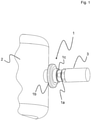
- FIG. 12 shows schematically a partial view of a fluid-containing unit 2, the content of which is measured by a sensor 3.
- the unit 2 comprises in particular a container containing a liquid, a tank, a pipeline, a fitting or the like, with the sensor 3 determining a pressure, a temperature or any other physical variable inside the unit 2 .
- the sensor 3 is connected to the unit 2 by means of a connecting device 1 according to the invention.
- the connecting device 1 comprises a first mounting section 1a on which the sensor 3 can be mounted. Furthermore, the connecting device 1 comprises a second mounting section 1b which can be mounted on the unit 2 . Between the first and the second mounting portion 1a and 1b is a central region 1c, the at least one in which Figure 2a shown, has bore 1d on its circumference. By this it is possible that from the unit 2 unintentionally leaking or leaking liquid can drain through one of the holes 1d.
- the connecting device 1 comprises a leakage ring 1e covering the bore 1d of the central region 1c, sealed with respect to the central region 1c and rotatable, the leakage ring 1e having a leakage outlet 1f on its periphery.
- the leakage outlet 1f is intended to be located in a region of a lowest position of the circumference of the leakage ring 1e in an operative position.
- the sensor 3 makes it possible for the sensor 3 to be mounted independently of the position of the leakage outlet 1f by turning the connecting device 1 into an optimal position relative to the unit 2 and the leakage outlet 1f of the leakage ring 1e by simply turning the same in the area a lowermost position or to the lowest position in the operating position in accordance with a requirement of a directive or a standard norm.
- the first assembly section 1a preferably comprises a screw connection 4, which enables the sensor 3 to be screwed onto the connecting device 1 in a simple manner.
- the second assembly section 1b comprises a flange connection 5, in particular a tri-clamp connection, as a result of which the connection device 1 together with the sensor 3 can be attached to the unit 2 very easily.
- the sensor 3 can be adjusted by simply turning the connecting device 1 into an optimal position with regard to readability of its display or its cable feed or wiring. After aligning the sensor 3, the leakage outlet 1f can be brought into the intended operating position by simply turning the leakage ring 1e.
- Both the connection between the first mounting section 1a and the sensor 3 and between the second mounting section 1b and the unit 2 are designed to be hermetically sealed. Tightness is ensured by the screw connection 4 on the side of the first assembly section 1a.
- On the side of the second assembly section 1b is the tightness of the flange connection 5, in particular the tri-clamp connection, produced by a sealing arrangement 5a.
- the sealing arrangement 5a comprises a sealing membrane, for example, which seals off the unit 2 from the sensor 3 .
- liquid from the unit 2 can inadvertently run into a collection groove 12 and drain through the bore 1d.
- the collecting groove 12 is provided on an inner side of the center portion 1c of the connecting device 1 and connects all the bores 1d of the center portion 1c with each other.
- the leakage ring 1e is sealed by means of two seals 6 in relation to the central region 1c of the connecting device 1. Despite the two seals 6, the leakage ring 1e can be rotated with respect to the central region 1c of the connecting device 1.
- the leakage ring 1e has a circumferential groove 7, in particular on an inside, which is wider than the bore 1d of the central region 1c of the connecting device 1 and covers all of the bores 1d in the central region 1c.
- a radially outwardly directed outlet bore 8 is connected to the groove 7 so that the groove 7 together with the outlet bore 8 forms the leakage outlet 1f of the leakage ring 1d.
- the groove 7 covers all bores 1d of the central area 1c and the outlet bore 8 connected to the groove 7 is located in the area of the lowest position of the leakage ring 1e, the liquid escaping unintentionally from the unit 2 can escape through one of the bores 1d of the Leak in the middle region 1c and ultimately flow through the outlet bore 8 via the groove 7 .
- the figure 3 shows a perspective sectional view of a preferred embodiment of the connecting device 1, without the unit 2 and the sensor 3.
- the first Mounting section 1a has a thread with which the sensor 3 can be mounted on the connecting device 1 .
- a smooth step can also be provided for a press fit of the sensor 3 to the connecting device 1 on the side of the first mounting section 1a.
- the second assembly section 1b includes a flange 9 with which the tri-clamp connection can be produced.
- the flange 9 has a groove 10 in which the sealing arrangement 5a is provided.
- the central region 1c has ten bores 1d, it being possible for liquid to escape through at least one of the bores 1d. All bores 1d are connected to one another on the inside of the central area 1c via the collecting groove 12, so that a cavity is formed between the inside of the central area 1c and an outer surface of the sensor 3, into which liquid from the unit 2 can occur.
- the leakage ring 1e completely covers the bores 1d with its groove 7, so that the unintentionally leaking liquid can only flow into the groove 7 of the leakage ring 1e.
- the liquid can escape to the outside through the leakage outlet 1f of the leakage ring 1e, so that the leak can be indicated to a user in this way.
- leakage ring 1e is in contact with the flange 9 of the second mounting portion 1b on one side and with a snap ring 11 on the other side, so that the leakage ring 1e is rotatably held in position.
- a step a the sensor 3 is connected to the first assembly section 1a of the connecting device 1 .
- the connection can be made either by screwing or by pressing the sensor 3 onto the first assembly section 1a.
- the second assembly section 1b is connected to unit 2 by means of flange connection 5 .
- the connecting device 1 can also be connected first to the unit 2 and only then to the sensor 3 .
- the sensor 3 After connecting the connecting device 1 to the unit 2 and the sensor 3, the sensor 3 is aligned in a desired position by rotating the connecting device 1 via the central area 1c in step b) so that, for example, a display of the sensor 3 can be easily read or connections of the sensor 3 are aligned in such a way that a simple wiring of the sensor 3 can be carried out.
- the leakage ring 1e When the sensor 3 is aligned, the leakage ring 1e is rotated in a step c) so that the leakage outlet 1f is arranged in an area or at the lowest position of the circumference of the leakage ring 1e in the operating position.
- This makes it easy to meet a standard requirement, for example in the food industry, namely the positioning of a leakage indicator at the lowest possible point of the connection between the sensor 3 and the unit 2 containing the fluid.
- the position of the sensor 3 remains adjustable so that, as required, for example for better readability or for simple wiring of the sensor 3, the sensor 3 can be aligned after connection to the unit 2 without the lowest point of the leakage -Having to give up outlet 1f in the operating position.
Landscapes
- Physics & Mathematics (AREA)
- General Physics & Mathematics (AREA)
- Examining Or Testing Airtightness (AREA)
- Measuring Fluid Pressure (AREA)
Abstract
Description
- Die Erfindung betrifft eine Verbindungsvorrichtung zum Verbinden eines Sensors mit einer ein Fluid enthaltenden Einheit gemäß dem Anspruch 1.
- In der heutigen Industrie werden fast sämtliche verwendete Einheiten, wie beispielsweise Maschinen oder Behälter, mittels Sensoren überwacht. Ein Einsatz der Sensoren kann durch Richtlinien oder Standardnormen vorgegeben sein, die bei der Auslegung des Einsatzes der Sensoren einzuhalten sind.
- Beim Anschluss eines Sensors im Bereich der Lebensmittelindustrie oder bei sterilen Anwendungen ist es erforderlich, dass eine mikrobiologische Kontamination vermieden wird. Eine solche Kontamination kann entstehen, wenn Fluid bzw. Flüssigkeit in einen Totraum eindringt und dort verbleibt. Deshalb ist, wenn Dichtungen oder Membrane verwendet werden, um den Totraum von einem Produktbereich zu trennen, eine Leckageanzeige vorzusehen. Hierbei ist die Leckageanzeige wegen des Abfließens von leckendem Fluid nach unten, an einer möglichst untersten Stelle zu positionieren. Im einfachsten Fall besteht die Leckageanzeige aus einer Leckagebohrung, aus der das leckende Fluid (sichtbar) austreten kann. In diesem Zusammenhang ist unter Totraum ein Hohlraum zwischen der Einheit und dem Sensor zu verstehen, in den aus der Einheit leckende Fluid eintreten kann.
- Diese Positionierung der Leckagebohrung ist nicht immer möglich, da wenn die Leckagebohrung an dem Sensor vorgesehen ist und wenn der Sensor an die Einheit anzuschrauben ist, die endgültige Position der Leckagebohrung und die Positionen möglicher Sensoranschlüsse nicht wählbar sind, weil sie von einem Ende des Gewindes abhängen. Andererseits kann die geforderte unterste Position der Leckagebohrung derart gewährleistet werden, dass die Leckagebohrung an der Einheit fest angeordnet ist, beispielsweise durch entsprechendes Schweißen. Dann ist aber eine Dreh-Ausrichtung des an die Einheit anzuschraubenden Sensors nicht möglich, so dass dann die Drehlage des Sensors rein zufällig ist und z.B. insbesondere eine Ablesbarkeit einer Anzeige des Sensors und/oder eine Verkabelung erschwert sind, weil die Anzeige in einem zum Ablesen ungünstigen Winkel positioniert ist bzw. entsprechende Anschlüsse des Sensors für die Verkabelung sich in ungünstiger Lage befinden.
- Es ist eine Aufgabe der Erfindung, eine Verbindungsvorrichtung zum Verbinden eines Sensors mit einer ein Fluid enthaltenden Einheit zur Verfügung zu stellen, mit der ein einfaches Ausrichten eines Leckage-Auslasses unter Berücksichtigung einer Ausrichtung des Sensors möglich ist.
- Die Aufgabe wird erfindungsgemäß gelöst durch eine Verbindungsvorrichtung zum Verbinden eines Sensors mit einer ein Fluid enthaltenden Einheit mit den Merkmalen des Anspruchs 1. Hierbei umfasst die Verbindungsvorrichtung zum Verbinden eines Sensors mit einer ein Fluid enthaltenden Einheit, einen ersten Montageabschnitt, an den der Sensor montierbar ist, einen zweiten Montageabschnitt, der an die Einheit montierbar ist, einen zwischen dem ersten und zweiten Montageabschnitt liegenden Mittelbereich, der mindestens eine Bohrung auf seinem Umfang aufweist und einen die Bohrung des Mittelbereichs abdeckenden Leckage-Ring, der gegenüber dem Mittelbereich abgedichtet und drehbar ist, wobei der Leckage-Ring einen Leckage-Auslass auf seinem Umfang aufweist, der vorgesehen ist, im Bereich einer tiefsten Position des Umfangs des Leckage-Ringes in einer Betriebsposition angeordnet zu sein, damit eventuell vorhandenes Fluid ablaufen kann.
- Hierdurch ergibt sich insbesondere der Vorteil, dass das einfache Ausrichten des Leckage-Auslasses mittels des Leckage-Ringes gleichzeitig und unabhängig davon ein einfaches Ausrichten der Anzeige des Sensors in einer optimalen Lage, beispielsweise für eine Ablesbarkeit einer Anzeige des Sensors oder eine Verkabelung des Sensors, zulässt. Vorteilhafterweise umfasst die das Fluid enthaltende Einheit einen Tank, eine Rohrleitung, eine Armatur oder dergleichen.
- Gemäß einem bevorzugten Ausführungsbeispiel umfasst der erste Montageabschnitt eine Schraubverbindung. Hierdurch ist eine Montage der Verbindungsvorrichtung an die Einheit sehr einfach.
- Weiterhin umfasst gemäß einem weiteren bevorzugten Ausführungsbeispiel der zweite Montageabschnitt eine Flanschverbindung, insbesondere eine Tri-Clamp-Verbindung, wodurch eine Montage der Verbindungsvorrichtung an die Einheit und das Ausrichten des Sensors durch Drehen der Verbindungsvorrichtung zusammen mit dem Sensor besonders vereinfacht ist.
- Ferner ist es vorteilhaft, dass die Verbindung des ersten Montageabschnitts mit dem Sensor und die Verbindung des zweiten Montageabschnitts mit der Einheit hermetisch dicht ausgebildet ist.
- Die der Erfindung zugrundeliegende Aufgabe wird ferner von einem Verfahren zum Montieren eines Sensors mittels einer Verbindungsvorrichtung an eine ein Fluid enthaltende Einheit dadurch gelöst, dass das Verfahren die Schritte umfasst:
- a) Montieren des Sensors an einen ersten Montageabschnitt der Verbindungsvorrichtung und Montieren eines zweiten Montageabschnitts der Verbindungsvorrichtung an die Einheit,
- b) Ausrichten des Sensors in eine gewünschte Position des Sensors,
- c) Drehen eines Leckage-Ringes der Verbindungsvorrichtung, um einen am Umfang des Leckage-Ringes vorgesehenen Leckage-Auslass in einen Bereich einer tiefsten Position des Umfangs des Leckage-Ringes in einer Betriebsposition anzuordnen.
- Hieraus ergibt sich der Vorteil, dass sowohl der Leckage-Auslass an die unterste Stelle der Verbindung gemäß der Richtlinie oder der Standardnorm positionierbar ist, als auch der Sensor bezüglich seiner Ablesbarkeit oder seiner Verkabelungszugänglichkeit optimal ausgerichtet werden kann.
- Die Erfindung wird nachstehend auch hinsichtlich weiterer Vorteile und Merkmale unter Bezugnahme auf die beigefügte Zeichnung anhand von Ausführungsbeispielen erläutert. Die Figuren der Zeichnung zeigen in:
- Fig. 1
- eine schematische perspektivische Teilansicht einer mittels einer erfindungsgemäßen Verbindungsvorrichtung mit einem Sensor verbundenen Einheit,
- Fig. 2a
- eine schematische Schnittansicht des in der
Figur 1 gezeigten Ausführungsbeispiels, - Fig. 2b
- eine vergrößerte Detailansicht eines Leckage-Auslasses, und
- Fig. 3
- eine perspektivische Schnittansicht eines bevorzugten Ausführungsbeispiels der Verbindungsvorrichtung.
- Die
Figur 1 zeigt schematisch eine Teilansicht einer ein Fluid enthaltenden Einheit 2, deren Inhalt durch einen Sensor 3 gemessen wird. Die Einheit 2 umfasst insbesondere einen eine Flüssigkeit enthaltenden Behälter, einen Tank, eine Rohrleitung, eine Armatur oder dergleichen, wobei der Sensor 3 einen Druck, eine Temperatur oder irgendeine andere physikalische Größe im Innern der Einheit 2 bestimmt. - Der Sensor 3 ist mittels einer erfindungsgemäßen Verbindungsvorrichtung 1 mit der Einheit 2 verbunden.
- Die Verbindungsvorrichtung 1 umfasst einen ersten Montageabschnitt 1a, an den der Sensor 3 montierbar ist. Ferner umfasst die Verbindungsvorrichtung 1 einen zweiten Montageabschnitt 1b, der an die Einheit 2 montierbar ist. Zwischen dem ersten und dem zweiten Montageabschnitt 1a und 1b liegt ein Mittelbereich 1c, der mindestens eine, in der
Figur 2a dargestellte, Bohrung 1d auf seinem Umfang aufweist. Hierdurch ist es möglich, dass aus der Einheit 2 ungewollt auslaufende bzw. leckende Flüssigkeit durch eine der Bohrungen 1d ablaufen kann. - Erfindungsgemäß umfasst die Verbindungsvorrichtung 1 einen die Bohrung 1d des Mittelbereichs 1c abdeckenden Leckage-Ring 1e, der gegenüber dem Mittelbereich 1c abgedichtet und drehbar ist, wobei der Leckage-Ring 1e einen Leckage-Auslass 1f auf seinem Umfang aufweist. Der Leckage-Auslass 1f ist vorgesehen, in einem Bereich einer tiefsten Position des Umfangs des Leckage-Ringes 1e in einer Betriebsposition angeordnet zu sein. Hierdurch ist es möglich, dass der Sensor 3 unabhängig von der Position des Leckage-Auslass 1f durch Drehen der Verbindungsvorrichtung 1 in eine optimale Position zu der Einheit 2 montierbar ist und der Leckage-Auslass 1f des Leckage-Ringes 1e durch Drehen derselben einfach im Bereich einer untersten Position bzw. auf die tiefste Position in der Betriebsposition entsprechend einer Vorgabe einer Richtlinie oder einer Standardnorm eingestellt werden kann.
- In der
Figur 2a ist eine schematische Schnittansicht des in derFigur 1 dargestellten Ausführungsbeispiels gezeigt. Der erste Montageabschnitt 1a umfasst vorzugsweise eine Schraubverbindung 4, die ein einfaches Anschrauben des Sensors 3 an die Verbindungsvorrichtung 1 ermöglicht. Der zweite Montageabschnitt 1b umfasst eine Flanschverbindung 5, insbesondere eine Tri-Clamp-Verbindung, wodurch die Verbindungsvorrichtung 1 zusammen mit dem Sensor 3 sehr einfach an die Einheit 2 befestigt werden kann. Hierbei kann der Sensor 3 durch einfaches Drehen der Verbindungsvorrichtung 1 in eine optimale Lage bzgl. einer Ablesbarkeit seiner Anzeige oder seiner Kabelzuführung bzw. Verkabelung justiert werden. Nach dem Ausrichten des Sensors 3 kann der Leckage-Auslass 1f durch einfaches Drehen des Leckage-Ringes 1e in die vorgesehene Betriebsposition gebracht werden. - Sowohl die Verbindung zwischen dem ersten Montageabschnitt 1a und dem Sensor 3 als auch zwischen dem zweiten Montageabschnitt 1b und der Einheit 2 sind hermetisch dicht ausgebildet. Auf der Seite des ersten Montageabschnitts 1a ist die Dichtheit durch die Schraubverbindung 4 gewährleistet. Auf der Seite des zweiten Montageabschnitts 1b ist die Dichtheit der Flanschverbindung 5, insbesondere der Tri-Clamp-Verbindung, durch eine Dichtungsanordnung 5a hergestellt. Die Dichtungsanordnung 5a umfasst beispielsweise eine Dichtungsmembran, die die Einheit 2 gegenüber dem Sensor 3 abdichtet.
- Im Falle, dass eine Dichtheit der Dichtungsanordnung 5a bzw. der Dichtungsmembran nicht gewährleistet ist, kann ungewollt Flüssigkeit der Einheit 2 in eine Sammelnut 12 einlaufen und durch die Bohrung 1d ablaufen. Die Sammelnut 12 ist auf einer Innenseite des Mittelbereichs 1c der Verbindungsvorrichtung 1 vorgesehen und verbindet alle Bohrungen 1d des Mittelbereichs 1c miteinander.
- Wie aus der vergrößerten Detailansicht des Leckage-Auslasses 1f des Leckage-Ringes lein der
Figur 2b gezeigt, ist der Leckage-Ring 1e mittels zwei Dichtungen 6 gegenüber dem Mittelbereich 1c der Verbindungsvorrichtung 1 abgedichtet. Der Leckage-Ring 1e ist trotz der beiden Dichtungen 6 gegenüber dem Mittelbereich 1c der Verbindungsvorrichtung 1 drehbar. Hierbei weist der Leckage-Ring 1e insbesondere auf einer Innenseite eine umlaufende Nut 7 auf, die breiter als die Bohrung 1d des Mittelbereichs 1c der Verbindungsvorrichtung 1 ausgebildet ist und sämtliche Bohrungen 1d des Mittelbereichs 1c abdeckt. Mit der Nut 7 ist eine radial nach außen gerichtete Auslassbohrung 8 verbunden, so dass die Nut 7 zusammen mit der Auslassbohrung 8 den Leckage-Auslass 1f des Leckage-Ringes 1d bildet. - Dadurch, dass die Nut 7 alle Bohrungen 1d des Mittelbereichs 1c abdeckt und die mit der Nut 7 verbundene Auslassbohrung 8 im Bereich der tiefsten Position des Leckage-Ringes 1e angeordnet ist, kann die aus der Einheit 2 ungewollt austretende Flüssigkeit durch eine der Bohrungen 1d des Mittelbereichs 1c auslaufen und über die Nut 7 letztlich durch die Auslassbohrung 8 abfließen.
- Die
Figur 3 zeigt eine perspektivische Schnittansicht eines bevorzugten Ausführungsbeispiels der Verbindungsvorrichtung 1, ohne die Einheit 2 und den Sensor 3. Der erste Montageabschnitt 1a weist ein Gewinde auf, mit dem der Sensor 3 an die Verbindungsvorrichtung 1 montiert werden kann. Hierbei kann anstatt dem Gewinde auch ein glatter Absatz für eine Presspassung des Sensors 3 an die Verbindungsvorrichtung 1 auf der Seite des ersten Montageabschnitts 1a vorgesehen sein. - Der zweite Montageabschnitt 1b umfasst einen Flansch 9, mit dem die Tri-Clamp-Verbindung herstellbar ist. Der Flansch 9 weist eine Nut 10 auf, in der die Dichtungsanordnung 5a vorgesehen ist. Der Mittelbereich 1c weist bei dem gezeigten Ausführungsbeispiel zehn Bohrungen 1d auf, wobei durch zumindest eine der Bohrungen 1d auslaufende Flüssigkeit austreten kann. Alle Bohrungen 1d sind auf der Innenseite des Mittelbereichs 1c über die Sammelnut 12 miteinander verbunden, so dass sich ein Hohlraum zwischen der Innenseite des Mittelbereichs 1c und einer Außenfläche des Sensors 3 bildet, in den beispielsweise durch eine Undichtigkeit der Dichtungsanordnung 5a Flüssigkeit von der Einheit 2 eintreten kann.
- Der Leckage-Ring 1e deckt vollständig mit seiner Nut 7 die Bohrungen 1d ab, so dass die ungewollt auslaufende Flüssigkeit nur in die Nut 7 des Leckage-Ringes 1e fließen kann. Durch den Leckage-Auslass 1f des Leckage-Ringes 1e kann die Flüssigkeit ins Freie austreten, so dass einem Nutzer auf diese Weise die Undichtigkeit angezeigt werden kann.
- Ferner ist der Leckage-Ring 1e auf einer Seite mit dem Flansch 9 des zweiten Montageabschnitts 1b und auf der anderen Seite mit einem Sicherungsring 11 in Kontakt, so dass der Leckage-Ring 1e drehbar in Position gehalten ist.
- Eine Montage der obigen Verbindungsvorrichtung 1 wird wie folgt durchgeführt. Der Sensor 3 wird in einem Schritt a) mit dem ersten Montageabschnitt 1a der Verbindungsvorrichtung 1 verbunden. Hierbei kann die Verbindung entweder durch Aufschrauben oder durch Aufpressen des Sensors 3 auf den ersten Montageabschnitt 1a geschehen. Der zweite Montageabschnitt 1b wird mittels der Flanschverbindung 5 mit der Einheit 2 verbunden. Selbstverständlich kann die Verbindungsvorrichtung 1 auch zuerst mit der Einheit 2 und erst danach mit dem Sensor 3 verbunden werden.
- Nach dem Verbinden der Verbindungsvorrichtung 1 mit der Einheit 2 und dem Sensor 3 wird durch Drehen der Verbindungsvorrichtung 1 über den Mittelbereich 1c in einem Schritt b) der Sensor 3 in eine gewünschte Position so ausgerichtet, dass beispielsweise ein Ablesen eines Displays des Sensors 3 einfach durchführbar ist oder Anschlüsse des Sensors 3 derart ausgerichtet sind, dass eine einfache Verkabelung des Sensors 3 durchgeführt werden kann.
- Wenn der Sensor 3 ausgerichtet ist, wird in einem Schritt c) der Leckage-Ring 1e gedreht, so dass der Leckage-Auslass 1f in einem Bereich bzw. an der tiefsten Position des Umfangs des Leckage-Ringes 1e in der Betriebsposition angeordnet ist. Hierdurch ist eine Standardvorgabe, beispielsweise der Lebensmittelindustrie, einfach zu erfüllen, nämlich die Positionierung einer Leckageanzeige an der möglichst untersten Stelle der Verbindung zwischen dem Sensor 3 und der das Fluid enthaltenden Einheit 2.
- Zusätzlich bleibt der Sensor 3 in seiner Position justierbar, so dass je nach Bedarf, beispielsweise für eine bessere Ablesbarkeit oder für eine einfache Verkabelung des Sensors 3, der Sensor 3 nach der Verbindung mit der Einheit 2 ausgerichtet werden kann, ohne die unterste Stelle des Leckage-Auslasses 1f in der Betriebsposition aufgeben zu müssen.
-
- 1
- Verbindungsvorrichtung
- 1a
- Erster Montageabschnitt
- 1b
- Zweiter Montageabschnitt
- 1c
- Mittelbereich
- 1d
- Bohrung
- 1e
- Leckage-Ring
- 1f
- Leckage-Auslass
- 2
- Einheit
- 3
- Sensor
- 4
- Schraubverbindung
- 5
- Flanschverbindung
- 5a
- Dichtungsanordnung
- 6
- Dichtungen
- 7
- Nut
- 8
- Auslassbohrung
- 9
- Flansch
- 10
- Nut
- 11
- Sicherungsring
- 12
- Sammelnut
Claims (6)
- Verbindungsvorrichtung (1) zum Verbinden eines Sensors (3) mit einer ein Fluid enthaltenden Einheit (2), umfassend
einen ersten Montageabschnitt (1a), an den der Sensor (3) montierbar ist, einen zweiten Montageabschnitt (1b), der an die Einheit (2) montierbar ist, einen zwischen dem ersten und dem zweiten Montageabschnitt (1a und 1b) liegenden Mittelbereich (1c), der mindestens eine Bohrung (1d) auf seinem Umfang aufweist, und
einen die Bohrung (1d) des Mittelbereichs (1c) abdeckenden Leckage-Ring (1e), der gegenüber dem Mittelbereich (1c) abgedichtet und drehbar ist, wobei der Leckage-Ring (1e) einen Leckage-Auslass (1f) auf seinem Umfang aufweist, der vorgesehen ist, im Bereich einer tiefsten Position des Umfangs des Leckage-Ringes (1e) in einer Betriebsposition angeordnet zu sein, damit eventuell vorhandenes Fluid ablaufen kann. - Verbindungsvorrichtung (1) nach Anspruch 1, wobei die das Fluid enthaltende Einheit (2) einen Tank, eine Rohrleitung, eine Armatur oder dergleichen, umfasst.
- Verbindungsvorrichtung (1) nach Anspruch 1 oder 2, wobei der erste Montageabschnitt (1a) eine Schraubverbindung (4) umfasst.
- Verbindungsvorrichtung (1) nach einem der vorhergehenden Ansprüche 1 bis 3, wobei der zweite Montageabschnitt (1b) eine Flanschverbindung (5), insbesondere eine Tri-Clamp-Verbindung, umfasst.
- Verbindungsvorrichtung (1) nach einem der vorhergehenden Ansprüche 1 bis 4, wobei die Verbindung des ersten Montageabschnitts (1a) mit dem Sensor (3) und die Verbindung des zweiten Montageabschnitts (1b) mit der Einheit (2) hermetisch dicht ausgebildet sind.
- Verfahren zum Montieren eines Sensors (3) mittels einer Verbindungsvorrichtung (1) nach einem der vorhergehenden Ansprüche 1 bis 5 an eine ein Fluid enthaltende Einheit (2), umfassend die Schritte:a) Montieren des Sensors (3) an einem ersten Montageabschnitt (1a) der Verbindungsvorrichtung (1) und Montieren eines zweiten Montageabschnitts (1b) der Verbindungsvorrichtung (1) an die Einheit (2),b) Ausrichten des Sensors (3) in eine gewünschte Position des Sensors (3),c) Drehen eines Leckage-Ringes (1e) der Verbindungsvorrichtung (1), um einen am Umfang des Leckage-Ringes (1e) vorgesehenen Leckage-Auslass (1f) in einem Bereich einer tiefsten Position des Umfangs des Leckage-Ringes (1e) in einer Betriebsposition anzuordnen.
Priority Applications (3)
| Application Number | Priority Date | Filing Date | Title |
|---|---|---|---|
| EP20186872.6A EP3943905B1 (de) | 2020-07-21 | 2020-07-21 | Verbindungsvorrichtung zum verbinden eines sensors mit einer ein fluid enthaltenden einheit |
| DK20186872.6T DK3943905T3 (da) | 2020-07-21 | 2020-07-21 | Forbindelsesanordning til forbindelse af en sensor med en enhed, der indeholder et fluid |
| US17/380,430 US11624673B2 (en) | 2020-07-21 | 2021-07-20 | Connecting device for connecting a sensor to a unit containing a fluid |
Applications Claiming Priority (1)
| Application Number | Priority Date | Filing Date | Title |
|---|---|---|---|
| EP20186872.6A EP3943905B1 (de) | 2020-07-21 | 2020-07-21 | Verbindungsvorrichtung zum verbinden eines sensors mit einer ein fluid enthaltenden einheit |
Publications (2)
| Publication Number | Publication Date |
|---|---|
| EP3943905A1 true EP3943905A1 (de) | 2022-01-26 |
| EP3943905B1 EP3943905B1 (de) | 2022-10-05 |
Family
ID=71738033
Family Applications (1)
| Application Number | Title | Priority Date | Filing Date |
|---|---|---|---|
| EP20186872.6A Active EP3943905B1 (de) | 2020-07-21 | 2020-07-21 | Verbindungsvorrichtung zum verbinden eines sensors mit einer ein fluid enthaltenden einheit |
Country Status (3)
| Country | Link |
|---|---|
| US (1) | US11624673B2 (de) |
| EP (1) | EP3943905B1 (de) |
| DK (1) | DK3943905T3 (de) |
Citations (2)
| Publication number | Priority date | Publication date | Assignee | Title |
|---|---|---|---|---|
| DE102005043346A1 (de) * | 2004-10-29 | 2006-05-04 | Caterpillar Inc., Peoria | Strömungsmittelsensor mit einem Niederdruck-Ablauf |
| US20170268910A1 (en) * | 2016-03-16 | 2017-09-21 | Endress+Hauser Conducta Gmbh+Co. Kg | Retractable assembly |
Family Cites Families (2)
| Publication number | Priority date | Publication date | Assignee | Title |
|---|---|---|---|---|
| US5869766A (en) * | 1995-10-03 | 1999-02-09 | Nt International, Inc. | Non-contaminating pressure transducer module |
| US8997715B2 (en) * | 2010-05-07 | 2015-04-07 | Cummins Intellectual Properties, Inc. | Common rail system with leak containment and detection |
-
2020
- 2020-07-21 DK DK20186872.6T patent/DK3943905T3/da active
- 2020-07-21 EP EP20186872.6A patent/EP3943905B1/de active Active
-
2021
- 2021-07-20 US US17/380,430 patent/US11624673B2/en active Active
Patent Citations (2)
| Publication number | Priority date | Publication date | Assignee | Title |
|---|---|---|---|---|
| DE102005043346A1 (de) * | 2004-10-29 | 2006-05-04 | Caterpillar Inc., Peoria | Strömungsmittelsensor mit einem Niederdruck-Ablauf |
| US20170268910A1 (en) * | 2016-03-16 | 2017-09-21 | Endress+Hauser Conducta Gmbh+Co. Kg | Retractable assembly |
Also Published As
| Publication number | Publication date |
|---|---|
| US11624673B2 (en) | 2023-04-11 |
| US20220026304A1 (en) | 2022-01-27 |
| DK3943905T3 (da) | 2022-11-21 |
| EP3943905B1 (de) | 2022-10-05 |
Similar Documents
| Publication | Publication Date | Title |
|---|---|---|
| EP0992717B1 (de) | Flachdichtungsring | |
| DE19916087A1 (de) | Anordnung zur Messung eines Fluiddrucks | |
| EP3299788A2 (de) | Flansch-satz für einen differenzdruck-messaufnehmer | |
| EP3943905B1 (de) | Verbindungsvorrichtung zum verbinden eines sensors mit einer ein fluid enthaltenden einheit | |
| EP1471341A1 (de) | Kleinbauende Sensorbefestigung an einem Behältnis mit einer konzentrischen Druckschraube | |
| DE3421604C2 (de) | Anordnung einer Schlauchhülse an einem Kanalkörper eines Fluidaggregates | |
| EP3309528A1 (de) | Tubusdruckmittler | |
| EP4158758B1 (de) | Antrieb mit einem gehäuse, einer adapterplatte und einer abdeckhaube | |
| DE202020104184U1 (de) | Verbindungsvorrichtung zum Verbinden eines Sensors mit einer ein Fluid enthaltenden Einheit | |
| DE69003544T3 (de) | Änderungen an hydraulischen Antischwingungsvorrichtungen. | |
| EP4038352B1 (de) | Hygienegerechter adapter für feldgerät | |
| WO2006030004A2 (de) | Gehäuse und gehäuseverbindung für sensoren | |
| DE102020134305B4 (de) | Membranventil | |
| DE19712171C1 (de) | Klemmverbinder | |
| WO2004090480A2 (de) | Messgerät zur bestimmung und/oder überwachung einer prozessgrösse | |
| DE112021007162T5 (de) | Rohrverbindung | |
| EP2072989B1 (de) | Rohrleitung für Flüssigkeiten mit einer Dichtklappe | |
| DE112022007264T5 (de) | Dichtungsstruktur für einen Drehmomentsensor und Roboter | |
| LU500882B1 (de) | Ankoppelvorrichtung zum drehmomentübertragenden Ankoppeln eines Antriebsmotors an ein Getriebe | |
| AT517981B1 (de) | Dreh- und Schwenkgelenk mit einer Drehachse und einer Schwenkachse | |
| DE102016103877B4 (de) | Motorlagerschild | |
| DE202026100617U1 (de) | Leitungsfitting eines Hydrauliksystems | |
| DE102019113471A1 (de) | Verbindungselement zum Verbinden zweier Fluidleitungen oder einer Fluidleitung mit einem Aggregat | |
| DE102013011633B3 (de) | Feldgerät | |
| DE102019127128B4 (de) | Adapterbauteil für eine fluidkommunizierende Verbindung von einem Hauptkühlkreislauf in einem Hauptgehäuse und einem Nebenkühlkreislauf in einem Nebengehäuse in einem Fahrzeug |
Legal Events
| Date | Code | Title | Description |
|---|---|---|---|
| PUAI | Public reference made under article 153(3) epc to a published international application that has entered the european phase |
Free format text: ORIGINAL CODE: 0009012 |
|
| STAA | Information on the status of an ep patent application or granted ep patent |
Free format text: STATUS: REQUEST FOR EXAMINATION WAS MADE |
|
| 17P | Request for examination filed |
Effective date: 20210715 |
|
| AK | Designated contracting states |
Kind code of ref document: A1 Designated state(s): AL AT BE BG CH CY CZ DE DK EE ES FI FR GB GR HR HU IE IS IT LI LT LU LV MC MK MT NL NO PL PT RO RS SE SI SK SM TR |
|
| STAA | Information on the status of an ep patent application or granted ep patent |
Free format text: STATUS: EXAMINATION IS IN PROGRESS |
|
| 17Q | First examination report despatched |
Effective date: 20220204 |
|
| GRAP | Despatch of communication of intention to grant a patent |
Free format text: ORIGINAL CODE: EPIDOSNIGR1 |
|
| STAA | Information on the status of an ep patent application or granted ep patent |
Free format text: STATUS: GRANT OF PATENT IS INTENDED |
|
| INTG | Intention to grant announced |
Effective date: 20220603 |
|
| GRAS | Grant fee paid |
Free format text: ORIGINAL CODE: EPIDOSNIGR3 |
|
| GRAA | (expected) grant |
Free format text: ORIGINAL CODE: 0009210 |
|
| STAA | Information on the status of an ep patent application or granted ep patent |
Free format text: STATUS: THE PATENT HAS BEEN GRANTED |
|
| AK | Designated contracting states |
Kind code of ref document: B1 Designated state(s): AL AT BE BG CH CY CZ DE DK EE ES FI FR GB GR HR HU IE IS IT LI LT LU LV MC MK MT NL NO PL PT RO RS SE SI SK SM TR |
|
| REG | Reference to a national code |
Ref country code: GB Ref legal event code: FG4D Free format text: NOT ENGLISH |
|
| REG | Reference to a national code |
Ref country code: CH Ref legal event code: EP |
|
| REG | Reference to a national code |
Ref country code: AT Ref legal event code: REF Ref document number: 1523005 Country of ref document: AT Kind code of ref document: T Effective date: 20221015 |
|
| REG | Reference to a national code |
Ref country code: IE Ref legal event code: FG4D Free format text: LANGUAGE OF EP DOCUMENT: GERMAN |
|
| REG | Reference to a national code |
Ref country code: DE Ref legal event code: R096 Ref document number: 502020001793 Country of ref document: DE |
|
| REG | Reference to a national code |
Ref country code: DK Ref legal event code: T3 Effective date: 20221117 |
|
| REG | Reference to a national code |
Ref country code: NL Ref legal event code: FP |
|
| REG | Reference to a national code |
Ref country code: SE Ref legal event code: TRGR |
|
| REG | Reference to a national code |
Ref country code: LT Ref legal event code: MG9D |
|
| PG25 | Lapsed in a contracting state [announced via postgrant information from national office to epo] |
Ref country code: PT Free format text: LAPSE BECAUSE OF FAILURE TO SUBMIT A TRANSLATION OF THE DESCRIPTION OR TO PAY THE FEE WITHIN THE PRESCRIBED TIME-LIMIT Effective date: 20230206 Ref country code: NO Free format text: LAPSE BECAUSE OF FAILURE TO SUBMIT A TRANSLATION OF THE DESCRIPTION OR TO PAY THE FEE WITHIN THE PRESCRIBED TIME-LIMIT Effective date: 20230105 Ref country code: LT Free format text: LAPSE BECAUSE OF FAILURE TO SUBMIT A TRANSLATION OF THE DESCRIPTION OR TO PAY THE FEE WITHIN THE PRESCRIBED TIME-LIMIT Effective date: 20221005 Ref country code: FI Free format text: LAPSE BECAUSE OF FAILURE TO SUBMIT A TRANSLATION OF THE DESCRIPTION OR TO PAY THE FEE WITHIN THE PRESCRIBED TIME-LIMIT Effective date: 20221005 Ref country code: ES Free format text: LAPSE BECAUSE OF FAILURE TO SUBMIT A TRANSLATION OF THE DESCRIPTION OR TO PAY THE FEE WITHIN THE PRESCRIBED TIME-LIMIT Effective date: 20221005 |
|
| PG25 | Lapsed in a contracting state [announced via postgrant information from national office to epo] |
Ref country code: RS Free format text: LAPSE BECAUSE OF FAILURE TO SUBMIT A TRANSLATION OF THE DESCRIPTION OR TO PAY THE FEE WITHIN THE PRESCRIBED TIME-LIMIT Effective date: 20221005 Ref country code: PL Free format text: LAPSE BECAUSE OF FAILURE TO SUBMIT A TRANSLATION OF THE DESCRIPTION OR TO PAY THE FEE WITHIN THE PRESCRIBED TIME-LIMIT Effective date: 20221005 Ref country code: LV Free format text: LAPSE BECAUSE OF FAILURE TO SUBMIT A TRANSLATION OF THE DESCRIPTION OR TO PAY THE FEE WITHIN THE PRESCRIBED TIME-LIMIT Effective date: 20221005 Ref country code: IS Free format text: LAPSE BECAUSE OF FAILURE TO SUBMIT A TRANSLATION OF THE DESCRIPTION OR TO PAY THE FEE WITHIN THE PRESCRIBED TIME-LIMIT Effective date: 20230205 Ref country code: HR Free format text: LAPSE BECAUSE OF FAILURE TO SUBMIT A TRANSLATION OF THE DESCRIPTION OR TO PAY THE FEE WITHIN THE PRESCRIBED TIME-LIMIT Effective date: 20221005 Ref country code: GR Free format text: LAPSE BECAUSE OF FAILURE TO SUBMIT A TRANSLATION OF THE DESCRIPTION OR TO PAY THE FEE WITHIN THE PRESCRIBED TIME-LIMIT Effective date: 20230106 |
|
| REG | Reference to a national code |
Ref country code: DE Ref legal event code: R097 Ref document number: 502020001793 Country of ref document: DE |
|
| PG25 | Lapsed in a contracting state [announced via postgrant information from national office to epo] |
Ref country code: SM Free format text: LAPSE BECAUSE OF FAILURE TO SUBMIT A TRANSLATION OF THE DESCRIPTION OR TO PAY THE FEE WITHIN THE PRESCRIBED TIME-LIMIT Effective date: 20221005 Ref country code: RO Free format text: LAPSE BECAUSE OF FAILURE TO SUBMIT A TRANSLATION OF THE DESCRIPTION OR TO PAY THE FEE WITHIN THE PRESCRIBED TIME-LIMIT Effective date: 20221005 Ref country code: EE Free format text: LAPSE BECAUSE OF FAILURE TO SUBMIT A TRANSLATION OF THE DESCRIPTION OR TO PAY THE FEE WITHIN THE PRESCRIBED TIME-LIMIT Effective date: 20221005 Ref country code: CZ Free format text: LAPSE BECAUSE OF FAILURE TO SUBMIT A TRANSLATION OF THE DESCRIPTION OR TO PAY THE FEE WITHIN THE PRESCRIBED TIME-LIMIT Effective date: 20221005 |
|
| PLBE | No opposition filed within time limit |
Free format text: ORIGINAL CODE: 0009261 |
|
| STAA | Information on the status of an ep patent application or granted ep patent |
Free format text: STATUS: NO OPPOSITION FILED WITHIN TIME LIMIT |
|
| PG25 | Lapsed in a contracting state [announced via postgrant information from national office to epo] |
Ref country code: SK Free format text: LAPSE BECAUSE OF FAILURE TO SUBMIT A TRANSLATION OF THE DESCRIPTION OR TO PAY THE FEE WITHIN THE PRESCRIBED TIME-LIMIT Effective date: 20221005 Ref country code: AL Free format text: LAPSE BECAUSE OF FAILURE TO SUBMIT A TRANSLATION OF THE DESCRIPTION OR TO PAY THE FEE WITHIN THE PRESCRIBED TIME-LIMIT Effective date: 20221005 |
|
| 26N | No opposition filed |
Effective date: 20230706 |
|
| PG25 | Lapsed in a contracting state [announced via postgrant information from national office to epo] |
Ref country code: SI Free format text: LAPSE BECAUSE OF FAILURE TO SUBMIT A TRANSLATION OF THE DESCRIPTION OR TO PAY THE FEE WITHIN THE PRESCRIBED TIME-LIMIT Effective date: 20221005 |
|
| PG25 | Lapsed in a contracting state [announced via postgrant information from national office to epo] |
Ref country code: MC Free format text: LAPSE BECAUSE OF FAILURE TO SUBMIT A TRANSLATION OF THE DESCRIPTION OR TO PAY THE FEE WITHIN THE PRESCRIBED TIME-LIMIT Effective date: 20221005 |
|
| PG25 | Lapsed in a contracting state [announced via postgrant information from national office to epo] |
Ref country code: MC Free format text: LAPSE BECAUSE OF FAILURE TO SUBMIT A TRANSLATION OF THE DESCRIPTION OR TO PAY THE FEE WITHIN THE PRESCRIBED TIME-LIMIT Effective date: 20221005 |
|
| REG | Reference to a national code |
Ref country code: BE Ref legal event code: MM Effective date: 20230731 |
|
| PG25 | Lapsed in a contracting state [announced via postgrant information from national office to epo] |
Ref country code: LU Free format text: LAPSE BECAUSE OF NON-PAYMENT OF DUE FEES Effective date: 20230721 |
|
| PG25 | Lapsed in a contracting state [announced via postgrant information from national office to epo] |
Ref country code: LU Free format text: LAPSE BECAUSE OF NON-PAYMENT OF DUE FEES Effective date: 20230721 |
|
| REG | Reference to a national code |
Ref country code: IE Ref legal event code: MM4A |
|
| PG25 | Lapsed in a contracting state [announced via postgrant information from national office to epo] |
Ref country code: BE Free format text: LAPSE BECAUSE OF NON-PAYMENT OF DUE FEES Effective date: 20230731 |
|
| PG25 | Lapsed in a contracting state [announced via postgrant information from national office to epo] |
Ref country code: IE Free format text: LAPSE BECAUSE OF NON-PAYMENT OF DUE FEES Effective date: 20230721 |
|
| PG25 | Lapsed in a contracting state [announced via postgrant information from national office to epo] |
Ref country code: IE Free format text: LAPSE BECAUSE OF NON-PAYMENT OF DUE FEES Effective date: 20230721 |
|
| PG25 | Lapsed in a contracting state [announced via postgrant information from national office to epo] |
Ref country code: BG Free format text: LAPSE BECAUSE OF FAILURE TO SUBMIT A TRANSLATION OF THE DESCRIPTION OR TO PAY THE FEE WITHIN THE PRESCRIBED TIME-LIMIT Effective date: 20221005 |
|
| PG25 | Lapsed in a contracting state [announced via postgrant information from national office to epo] |
Ref country code: BG Free format text: LAPSE BECAUSE OF FAILURE TO SUBMIT A TRANSLATION OF THE DESCRIPTION OR TO PAY THE FEE WITHIN THE PRESCRIBED TIME-LIMIT Effective date: 20221005 |
|
| PG25 | Lapsed in a contracting state [announced via postgrant information from national office to epo] |
Ref country code: CY Free format text: LAPSE BECAUSE OF FAILURE TO SUBMIT A TRANSLATION OF THE DESCRIPTION OR TO PAY THE FEE WITHIN THE PRESCRIBED TIME-LIMIT; INVALID AB INITIO Effective date: 20200721 |
|
| PG25 | Lapsed in a contracting state [announced via postgrant information from national office to epo] |
Ref country code: HU Free format text: LAPSE BECAUSE OF FAILURE TO SUBMIT A TRANSLATION OF THE DESCRIPTION OR TO PAY THE FEE WITHIN THE PRESCRIBED TIME-LIMIT; INVALID AB INITIO Effective date: 20200721 |
|
| PGFP | Annual fee paid to national office [announced via postgrant information from national office to epo] |
Ref country code: NL Payment date: 20250723 Year of fee payment: 6 |
|
| PGFP | Annual fee paid to national office [announced via postgrant information from national office to epo] |
Ref country code: DE Payment date: 20250722 Year of fee payment: 6 Ref country code: DK Payment date: 20250723 Year of fee payment: 6 |
|
| PGFP | Annual fee paid to national office [announced via postgrant information from national office to epo] |
Ref country code: IT Payment date: 20250731 Year of fee payment: 6 |
|
| PGFP | Annual fee paid to national office [announced via postgrant information from national office to epo] |
Ref country code: GB Payment date: 20250724 Year of fee payment: 6 |
|
| PGFP | Annual fee paid to national office [announced via postgrant information from national office to epo] |
Ref country code: AT Payment date: 20251020 Year of fee payment: 5 Ref country code: FR Payment date: 20250723 Year of fee payment: 6 |
|
| PGFP | Annual fee paid to national office [announced via postgrant information from national office to epo] |
Ref country code: SE Payment date: 20250723 Year of fee payment: 6 Ref country code: CH Payment date: 20250801 Year of fee payment: 6 |
|
| PG25 | Lapsed in a contracting state [announced via postgrant information from national office to epo] |
Ref country code: TR Free format text: LAPSE BECAUSE OF FAILURE TO SUBMIT A TRANSLATION OF THE DESCRIPTION OR TO PAY THE FEE WITHIN THE PRESCRIBED TIME-LIMIT Effective date: 20221005 |