EP3943835A1 - Oil separator and a chiller comprising the oil separator - Google Patents
Oil separator and a chiller comprising the oil separator Download PDFInfo
- Publication number
- EP3943835A1 EP3943835A1 EP21186754.4A EP21186754A EP3943835A1 EP 3943835 A1 EP3943835 A1 EP 3943835A1 EP 21186754 A EP21186754 A EP 21186754A EP 3943835 A1 EP3943835 A1 EP 3943835A1
- Authority
- EP
- European Patent Office
- Prior art keywords
- oil separator
- support member
- opposite end
- crossmember
- interior
- Prior art date
- Legal status (The legal status is an assumption and is not a legal conclusion. Google has not performed a legal analysis and makes no representation as to the accuracy of the status listed.)
- Granted
Links
Images



Classifications
-
- F—MECHANICAL ENGINEERING; LIGHTING; HEATING; WEAPONS; BLASTING
- F25—REFRIGERATION OR COOLING; COMBINED HEATING AND REFRIGERATION SYSTEMS; HEAT PUMP SYSTEMS; MANUFACTURE OR STORAGE OF ICE; LIQUEFACTION SOLIDIFICATION OF GASES
- F25B—REFRIGERATION MACHINES, PLANTS OR SYSTEMS; COMBINED HEATING AND REFRIGERATION SYSTEMS; HEAT PUMP SYSTEMS
- F25B31/00—Compressor arrangements
- F25B31/002—Lubrication
- F25B31/004—Lubrication oil recirculating arrangements
-
- F—MECHANICAL ENGINEERING; LIGHTING; HEATING; WEAPONS; BLASTING
- F25—REFRIGERATION OR COOLING; COMBINED HEATING AND REFRIGERATION SYSTEMS; HEAT PUMP SYSTEMS; MANUFACTURE OR STORAGE OF ICE; LIQUEFACTION SOLIDIFICATION OF GASES
- F25B—REFRIGERATION MACHINES, PLANTS OR SYSTEMS; COMBINED HEATING AND REFRIGERATION SYSTEMS; HEAT PUMP SYSTEMS
- F25B43/00—Arrangements for separating or purifying gases or liquids; Arrangements for vaporising the residuum of liquid refrigerant, e.g. by heat
- F25B43/003—Filters
-
- F—MECHANICAL ENGINEERING; LIGHTING; HEATING; WEAPONS; BLASTING
- F25—REFRIGERATION OR COOLING; COMBINED HEATING AND REFRIGERATION SYSTEMS; HEAT PUMP SYSTEMS; MANUFACTURE OR STORAGE OF ICE; LIQUEFACTION SOLIDIFICATION OF GASES
- F25B—REFRIGERATION MACHINES, PLANTS OR SYSTEMS; COMBINED HEATING AND REFRIGERATION SYSTEMS; HEAT PUMP SYSTEMS
- F25B43/00—Arrangements for separating or purifying gases or liquids; Arrangements for vaporising the residuum of liquid refrigerant, e.g. by heat
- F25B43/02—Arrangements for separating or purifying gases or liquids; Arrangements for vaporising the residuum of liquid refrigerant, e.g. by heat for separating lubricants from the refrigerant
-
- F—MECHANICAL ENGINEERING; LIGHTING; HEATING; WEAPONS; BLASTING
- F25—REFRIGERATION OR COOLING; COMBINED HEATING AND REFRIGERATION SYSTEMS; HEAT PUMP SYSTEMS; MANUFACTURE OR STORAGE OF ICE; LIQUEFACTION SOLIDIFICATION OF GASES
- F25B—REFRIGERATION MACHINES, PLANTS OR SYSTEMS; COMBINED HEATING AND REFRIGERATION SYSTEMS; HEAT PUMP SYSTEMS
- F25B2339/00—Details of evaporators; Details of condensers
- F25B2339/04—Details of condensers
- F25B2339/047—Water-cooled condensers
Definitions
- the following description relates to water-cooled heat exchangers and more specifically, water-cooled heat exchangers with an oil separator having integrated refrigerant distribution.
- a chiller is a machine that removes heat from a liquid via a vapor-compression or absorption refrigeration cycle. This liquid can then be circulated through a heat exchanger to cool equipment, or another process stream (such as air or process water).
- a typical chiller includes a compressor (e.g., a screw compressor), a condenser, an evaporator or cooler, an oil-refrigerant separator, an economizer and expansion devices. These components are connected to each other by tubing that carries a working fluid (e.g., refrigerant) through the chiller system.
- the evaporator typically includes a plurality of tubes that circulate water to be cooled.
- the condenser typically includes a plurality of tubes through which is circulated tower water to which heat is rejected.
- the compressor requires oil for lubrication which is typically entrained in the refrigerant.
- the combined oil and refrigerant mixture is carried through the compression cycle and then discharged into the oil separator where the oil must be removed from the refrigerant to allow for proper operation of the heat exchangers.
- the separated refrigerant is supplied to condenser and separated oil is returned to the compressor. From the oil separator, the clean refrigerant flows to the condenser.
- the oil separator is integrated with a heat exchanger (e.g., a condenser) which provides for among other things, a manufacturing cost savings.
- a heat exchanger e.g., a condenser
- Some integrated oil separators may include an off-centered refrigeration inlet, and a distributor for distributing the oil/refrigerant mixture into the body of the oil separator.
- Such oil separators may also include filtration devices such as wire mesh and demister pads for separating the incoming oil/refrigerant mixture. In general, separation occurs by the collision of the oil and refrigerant mixture on the walls of the oil separator. The oil is further separated from the mixture due to gravity and the filtration.
- an oil separator including: an exterior shell having opposite end walls defining a first interior, and a first and second opening fluidly communicative with the first interior; a plurality of baffles operably coupled to and extending from at least a first opposite end wall, each baffle comprising: a first support member generally parallel to a second support member, each operably coupled, and in an orientation that is generally perpendicular, to at least the first opposite end wall, and a crossmember operably coupled between the first support member and the second support member, the crossmember having a width dimension that is less than the width dimension of the first support member and the second support member, forming an orifice between the crossmember and the at least first opposite end wall; and a distributor integrated within the exterior shell to define a second interior within the first interior.
- At least one of the crossmember, the first support member and the second support member comprises a concave surface for deflecting the flow of a fluid.
- the internal width of the orifice between the support members comprises a dimension of less than or equal to about 45 millimeters.
- the internal depth of the orifice between the crossmember and the at least first opposite end wall comprises a dimension of less than or equal to about 20 millimeters.
- the width of the baffle across the support members and the crossmember comprise a dimension of less than or equal to about 75 millimeters.
- the length of a support member comprises a dimension of less than or equal to about 40 millimeters.
- the distributor has a length, which is slightly less than that of the exterior shell, being disposed to define opposite spaces between a first opposite end and a second opposite end thereof and the opposite end walls and being sealed to the exterior shell along the length to form first and second passageways from the first opening to the opposite spaces.
- a first filter media cartridge and a second filter media cartridge are disposed within the first interior between the opposite spaces and the second opening.
- a flow component for an oil separator including: an end wall defining an exterior shell of an oil separator having an integrated distributor disposed within the oil separator; and a plurality of baffles operably coupled to and extending from the end wall, each baffle comprising a first support member generally parallel to a second support member, each operably coupled, and in an orientation that is generally perpendicular, to the at least the first opposite end wall, and a crossmember operably coupled between the first support member and the second support member, the crossmember having a width dimension that is less than the width dimension of the first support member and the second support member, forming an orifice between the crossmember and the at least first opposite end wall.
- At least one of the crossmember, the first support member and the second support member comprises a concave surface for deflecting the flow of a fluid.
- At least one of the crossmember, the first support member and the second support member comprises a concave surface for deflecting the flow of a fluid.
- the internal width of the orifice between the support members comprises a dimension of less than or equal to about 45 millimeters.
- the internal depth of the orifice between the crossmember and the at least first opposite end wall comprises a dimension of less than or equal to about 20 millimeters.
- the width of the baffle across the support members and the crossmember comprise a dimension of less than or equal to about 75 millimeters.
- the length of a support member comprises a dimension of less than or equal to about 40 millimeters.
- an oil separator comprising the flow component of the second aspect of the invention.
- the oil separator may be an oil separator as recited herein with reference to the first aspect of the invention, and may comprise any of the features of the oil separator of the first aspect of the invention.
- a chiller assembly including: a compressor; an oil separator including, an exterior shell having opposite end walls defining a first interior, and a first and second opening fluidly communicative with the first interior, a plurality of baffles operably coupled to and extending from at least a first opposite end wall, each baffle comprising: a first support member generally parallel to a second support member, each operably coupled, and in an orientation that is generally perpendicular, to the at least the first opposite end wall, and a crossmember operably coupled between the first support member and the second support member, the crossmember having a width dimension that is less than the width dimension of the first support member and the second support member, forming an orifice between the crossmember and the at least first opposite end wall; and a distributor integrated within the exterior shell to define a second interior within the first interior.
- the chiller assembly includes a single discharge pipe sub-assembly fluidly interposed between the compressor and the oil separator.
- the distributor comprises a cross-sectional area which is substantially similar to that of the single discharge pipe sub-assembly.
- the internal width of the orifice between the support members comprises a dimension of less than or equal to about 45 millimeters.
- the internal depth of the orifice between the crossmember and the opposite end wall comprises a dimension of less than or equal to about 20 millimeters.
- a chiller assembly comprising a compressor; and an oil separator as recited herein with reference to any aspect of the invention.
- the chiller assembly may comprise a flow component as recited herein with reference to any aspect of the invention.
- an integrated oil separator is provided with a distributor such that fluid (e.g., an oil/refrigerant mixture) distribution occurs within the elongated body of the oil separator interior.
- the oil separator is defined by opposing end walls in fluid communication with the distributor.
- fluid will flow from a discharge pipe of a compressor into an inlet port of the oil separator, which is integrated with a heat exchanger shell, such as a condenser.
- the inlet port may be in an off-centered position (e.g., on either side from center of the oil separator).
- the distributor will distribute the fluid into one or both ends of the oil separator in the flow direction of the opposing end walls.
- the end walls of an oil separator have a generally flat surface; however when combined with the off-centered positioning of the inlet port, this may result in a non-uniform flow pattern and the creation of unwanted flow vortices within the body of the oil separator.
- a plurality of baffles to at least one opposing end wall to deflect the flow of fluid as it flows from the distributor into the oil separator body, the fluid flow velocity into the oil separator, before entering the filtration devices (e.g., mesh and demister pads) may be reduced, resulting in improved flow, a reduced occurrence of flow vortices, and with a negligible impact on total pressure drop within the oil separator.
- the chiller assembly 10 includes a compressor 11, an oil separator 12 and a single discharge pipe sub-assembly 13.
- the compressor 11 is configured to compress refrigerant and to discharge the compressed refrigerant at an initial pressure to the single discharge pipe sub-assembly 13.
- the single discharge pipe sub-assembly 13 is fluidly interposed between the compressor 11 and the oil separator 12 and conveys the compressed refrigerant at the initial pressure from the compressor 11 to the oil separator 12.
- the single discharge pipe sub-assembly 13 may be formed of steel or other similar or suitable materials and includes a weld joint 14 at an interface between an end 130 thereof and the oil separator 12.
- the oil separator 12 includes an exterior shell 20, a distributor 30 and first and second filter media cartridges 41 and 42.
- the distributor 30 is integrated within the exterior shell 20 and has a cross-sectional area which is substantially similar to the cross-sectional area of the single discharge pipe sub-assembly 13.
- the distributor internal cross-section size will be equal to the discharge pipe size so that the integrated oil separator 12 will induce no additional pressure drop or change in thermal properties of the refrigerant.
- the integrated oil separator assembly with the compressor 11 will also be characterized in that copper pipes of conventional chillers will be replaced with a steel pipe. Similarly, silver brazing process that are used with conventional assemblies may be replaced with welding.
- the exterior shell 20 is formed to define a first interior 21, a first opening 22, which is fluidly communicative with the first interior 21 and a second opening 23, which is also fluidly communicative with the first interior 21.
- the exterior shell 20 also includes a separate refrigerant outlet configured to allow oil and the refrigerant to separately flow from the oil separator.
- the distributor 30 is integrated within the exterior shell 20 to define a second interior 31 within the first interior 21.
- the distributor 30 has a longitudinal length L1, which is slightly less than a longitudinal length L2 of the exterior shell 20.
- the distributor 30 is disposed within the exterior shell 20 to thus define opposite spaces 32, 33 between opposite ends 34, 35 of the distributor 30 and corresponding distributor opposite ends 24, 25 of the exterior shell 20.
- the distributor 30 is also sealed to the exterior shell 20 by seals (not shown) that extend along the edges of the distributor 30 along an entirety of the length L1.
- the distributor 30 thus forms first and second passageways P1 and P2 from the first opening 22 to the opposite spaces 32, 33.
- First and second filter media cartridges 41, 42 are respectively disposed within the first interior 21 between corresponding ones of the opposite spaces 32, 33 and the second opening 23.
- the exterior shell 20 may have a substantially semi-circular cross-sectional shape and may include a flat side 201, a curved side 202 that protrudes away from the flat side 201 and opposite end walls 203.
- the opposite end walls 203 are provided at respective opposite ends of the flat side 201 and the curved side 202.
- the flat side 201, the curved side 202 and the opposite end walls 203 cooperatively define the first interior 21.
- At least one of the opposite end walls 203 may have a plurality of baffles 205 as further described below in reference to FIGS. 5-7 .
- the cross-sectional area of the distributor 30 is substantially similar to the cross-sectional area of the single discharge pipe sub-assembly 13, such that fluid moving through the single discharge pipe sub-assembly 13 at the initial pressure moves through the distributor 30, the opposite spaces 32, 33 and into the first interior 21 after interacting with baffles 205, without experiencing a pressure drop. That is, the fluid passes through the opposite spaces 32, 33 at substantially a same pressure as the initial pressure.
- the distributor may have a substantially trapezoidal shape (with the curved side 202) serving as one of the trapezoidal sides or other similar shapes to be described in greater detail below.
- the distributor 30 may include a base 301, sidewalls 302, 303 that extend in a same direction from opposite edges of the base 301.
- the distributor 30 is disposed within the first interior 21 at an offset position relative to a mid-line of the exterior shell 20 such that the sidewalls 302, 303 extend in the same direction from the opposite edges of the base 301 toward an interior surface of the curved side 202 of the exterior shell 20.
- Seals may be sealably interposed between distal edges of the sidewalls 302, 303 and the interior surface of the curved side 202. Respective widths of the sidewalls 302, 303 dispose the base 301 at a depth from the interior surface of the curved side 202. The base 301, the sidewalls 302, 303 and the curved side 202 thus define the second interior 31.
- fluid received by the oil separator 12 includes a mixture of refrigerant and oil that was compressed in the compressor 11 and conveyed to the oil separator 12 through the single discharge pipe sub-assembly 13.
- the fluid enters the exterior shell 20 via first opening 22 and is contained within the sealed second interior 31.
- the fluid thus moves through either the first or the second passageways P1 and P2 within the second interior 31 and along the length L1 of the distributor 30 as the seals prevent the fluid from flowing in any other direction.
- the fluid reaches the opposite spaces 32, 33.
- the fluid then passes through the opposite spaces 32, 33 and turns back into the first interior 21 due to interactions with the opposite end walls 203 and baffles 205, and flows through the first and second filter media cartridges 41, 42 toward the second opening 23.
- Deflecting the flow of fluid using a plurality of baffles 205 has the benefit of reducing the formation of flow vortices that can occur in the first interior 21, and which will also cause a lack of fluid distribution uniformity in the first interior 21.
- the flow distribution of fluid across the filter media cartridges 41, 42 is reduced.
- the filter media cartridges 41, 42 are wire mesh (e.g., demister).
- the flow distribution index (FDI) may be used to obtain the deviation from the average flow velocity.
- an oil separator with internal distributor may have an average FDI at the entrance to the wire mesh/demister pads equal to or greater than 0.6 and equal to or less than 0.8.
- the FDI may be improved, indicating better distribution of flow.
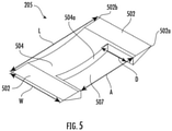
- Each baffle 205 may include a pair of support members 502, 503, wherein a first support member 502 is generally parallel to a second support member 503, each operably coupled, and in an orientation that is generally perpendicular, to at least the first opposite end wall, and a crossmember 504 operably coupled between the first support member 502 and the second support member 503, the crossmember 504 having a width dimension that is less than the width dimension of the first support member 502 and the second support member 503, forming an orifice between the crossmember 504 and the at least first opposite end wall 203.
- Baffle 205 may be constructed from, and coupled to the at least one opposite end wall 203 by, any material, preferably metal or metal alloy, that may withstand the fluid forces of fluid acting upon the baffles 205.
- a baffle 205 may be of any shape that serves to interact with fluid so as to reduce the effect of flow vortices that may occur within the first interior 21, as fluid flows from the distributor 30 through the opposite spaces 32, 33 and into the first interior 21.
- a baffle 205 may have any dimension (length, width, depth) depending on a variety of factors, such as size of the oil separator 12 and/or the rate of fluid flow through the oil separator.
- baffle 205 has a square U-shape, including two support members 502, 503 extending from an operably coupled crossmember 504.
- at least one of the crossmember 504 and the support members 502, 503 have a concave surface for deflecting fluid flowing from the distributor 30 into the first interior 21.
- baffles 205 positioned in proximity to the first opening 22, may deflect approximately 30-40% of fluid flow from the distributor 30, with the remaining portion flowing directly into the first interior 21.
- flow distribution of fluid in the first interior 21 may be measured (e.g., flow distribution index (FDI)) with higher values indicating improved (e.g., more uniform) flow distribution.
- FDI flow distribution index
- an oil separator 12 without deflecting baffles 205 may have a FDI of less than 0.50, while an oil separator 12 with deflecting baffles 205 may have a higher FDI (e.g., equal to or greater than 0.60).
- Each support member 502, 503 has a proximal end (e.g., 502a) that operably couples the baffle 205 to the at least one opposite end wall 203.
- the support members 502, 503 and the crossmember 504 have a total length ( l ) dimension that is generally equal to or less than 75 millimeters (mm).
- each support member has a width (w) dimension measurable from a proximal end 502a to a distal end 502b that is generally equal to or less than 40mm.
- the crossmember 504 of baffle 205 is has a width dimension that is less than the width dimension of the two support members 502, 503 such that when baffle 205 is operably coupled to at least one opposite end wall 203, an orifice 507 is formed.
- the orifice 507 has a length ( a ) dimension as measured from the medial facing side of each support member 502,503 that is generally equal to or less than 45mm.
- the orifice 507 has a depth (d) dimension measured from the proximal end 502a to an interior surface 504a of the crossmember 504 that is generally equal to or less than 20mm.
- the orifice 507 permits a portion of the fluid from the distributor 30, to flow through to the first interior 21.
- the orifice 507 may have the further benefit of minimizing any potential pressure increase as fluid flows from the distributor 30 to the first interior 21.
- FIGS. 2 , 3 , 6 and 7 show various views of a plurality of baffles 205 is in accordance with embodiments of the disclosure.
- a plurality of baffles 205 are operably coupled to at least one opposite end wall 203 as illustrated in FIG. 2 .
- baffles 205 may be on both opposite end walls 203 as illustrated in the side view of FIG. 3 and the top view of FIG. 6 .
- the baffles 205 may be coupled to the internal portion of the shell 20, for example, within the first interior 21 (not shown).
- an axial view of the oil separator is provided to illustrate one non-limiting embodiment of the plurality of baffles 205 as coupled to at least one opposite end wall 203, however omitting other details such as the distributor, for clarity.
- the vertical plane of the opposite end wall 203 may be described in terms of x, y coordinates, having an x-axis and a y-axis.
- the position of a baffle 205 along the plane of the opposite end wall 203 may be generally perpendicular to the y-axis, as illustrated by baffle 205a.
- the position of a baffle may be at an angle ( ⁇ ) generally less than forty-five degrees (45°) from the x-axis as illustrated by baffle 205b.
- the number of baffles 205 coupled to at least one opposite end wall 203, and the spacing between baffles 205, may vary based on a variety factors, including size of the oil separator 12, the rate of fluid flow through the oil separator, and the location of the first opening 22.
Landscapes
- Engineering & Computer Science (AREA)
- Physics & Mathematics (AREA)
- Mechanical Engineering (AREA)
- Thermal Sciences (AREA)
- General Engineering & Computer Science (AREA)
- Chemical & Material Sciences (AREA)
- Analytical Chemistry (AREA)
- Power Engineering (AREA)
- Separating Particles In Gases By Inertia (AREA)
Abstract
Description
- The application claims the benefit of
U.S. Provisional Application No. 62/705,890 filed July 21, 2020 - The following description relates to water-cooled heat exchangers and more specifically, water-cooled heat exchangers with an oil separator having integrated refrigerant distribution.
- A chiller is a machine that removes heat from a liquid via a vapor-compression or absorption refrigeration cycle. This liquid can then be circulated through a heat exchanger to cool equipment, or another process stream (such as air or process water). A typical chiller includes a compressor (e.g., a screw compressor), a condenser, an evaporator or cooler, an oil-refrigerant separator, an economizer and expansion devices. These components are connected to each other by tubing that carries a working fluid (e.g., refrigerant) through the chiller system. The evaporator typically includes a plurality of tubes that circulate water to be cooled. The condenser typically includes a plurality of tubes through which is circulated tower water to which heat is rejected. The compressor requires oil for lubrication which is typically entrained in the refrigerant. The combined oil and refrigerant mixture is carried through the compression cycle and then discharged into the oil separator where the oil must be removed from the refrigerant to allow for proper operation of the heat exchangers. The separated refrigerant is supplied to condenser and separated oil is returned to the compressor. From the oil separator, the clean refrigerant flows to the condenser.
- In some chiller systems, the oil separator is integrated with a heat exchanger (e.g., a condenser) which provides for among other things, a manufacturing cost savings. Some integrated oil separators may include an off-centered refrigeration inlet, and a distributor for distributing the oil/refrigerant mixture into the body of the oil separator. Such oil separators may also include filtration devices such as wire mesh and demister pads for separating the incoming oil/refrigerant mixture. In general, separation occurs by the collision of the oil and refrigerant mixture on the walls of the oil separator. The oil is further separated from the mixture due to gravity and the filtration. When refrigerant enters the oil separator it may impinge on the side walls of the oil separator, and if the distribution of refrigerant is uneven, then oil separation efficiency may be reduced. In addition, if the flow within the oil separator body is non-uniform as it enters the filtration devices, then separation efficiency may be further reduced and permit oil particles to remain in the refrigerant as the refrigerant flows to the compressor. This in turn reduces the efficiency of the HVAC system and may lead to reliability and quality issues. What is needed then, is a system and method for improving the flow and distribution of refrigerant within an integrated oil separator, having off-centered refrigerant inlet.
- According to a first aspect of the invention, there is provided an oil separator including: an exterior shell having opposite end walls defining a first interior, and a first and second opening fluidly communicative with the first interior; a plurality of baffles operably coupled to and extending from at least a first opposite end wall, each baffle comprising: a first support member generally parallel to a second support member, each operably coupled, and in an orientation that is generally perpendicular, to at least the first opposite end wall, and a crossmember operably coupled between the first support member and the second support member, the crossmember having a width dimension that is less than the width dimension of the first support member and the second support member, forming an orifice between the crossmember and the at least first opposite end wall; and a distributor integrated within the exterior shell to define a second interior within the first interior.
- Optionally, at least one of the crossmember, the first support member and the second support member comprises a concave surface for deflecting the flow of a fluid.
- Optionally, the internal width of the orifice between the support members comprises a dimension of less than or equal to about 45 millimeters.
- Optionally, the internal depth of the orifice between the crossmember and the at least first opposite end wall comprises a dimension of less than or equal to about 20 millimeters.
- Optionally, the width of the baffle across the support members and the crossmember comprise a dimension of less than or equal to about 75 millimeters.
- Optionally, the length of a support member comprises a dimension of less than or equal to about 40 millimeters.
- Optionally, the distributor has a length, which is slightly less than that of the exterior shell, being disposed to define opposite spaces between a first opposite end and a second opposite end thereof and the opposite end walls and being sealed to the exterior shell along the length to form first and second passageways from the first opening to the opposite spaces.
- Optionally, a first filter media cartridge and a second filter media cartridge are disposed within the first interior between the opposite spaces and the second opening.
- According to a second aspect of the invention, there is provided a flow component for an oil separator including: an end wall defining an exterior shell of an oil separator having an integrated distributor disposed within the oil separator; and a plurality of baffles operably coupled to and extending from the end wall, each baffle comprising a first support member generally parallel to a second support member, each operably coupled, and in an orientation that is generally perpendicular, to the at least the first opposite end wall, and a crossmember operably coupled between the first support member and the second support member, the crossmember having a width dimension that is less than the width dimension of the first support member and the second support member, forming an orifice between the crossmember and the at least first opposite end wall.
- Optionally, at least one of the crossmember, the first support member and the second support member comprises a concave surface for deflecting the flow of a fluid.
- Optionally, at least one of the crossmember, the first support member and the second support member comprises a concave surface for deflecting the flow of a fluid.
- Optionally, the internal width of the orifice between the support members comprises a dimension of less than or equal to about 45 millimeters.
- Optionally, the internal depth of the orifice between the crossmember and the at least first opposite end wall comprises a dimension of less than or equal to about 20 millimeters.
- Optionally, the width of the baffle across the support members and the crossmember comprise a dimension of less than or equal to about 75 millimeters.
- Optionally, the length of a support member comprises a dimension of less than or equal to about 40 millimeters.
According to a third aspect of the invention, there is provided an oil separator comprising the flow component of the second aspect of the invention. The oil separator may be an oil separator as recited herein with reference to the first aspect of the invention, and may comprise any of the features of the oil separator of the first aspect of the invention. - According to a fourth aspect of the present invention, there is provided a chiller assembly, including: a compressor; an oil separator including, an exterior shell having opposite end walls defining a first interior, and a first and second opening fluidly communicative with the first interior, a plurality of baffles operably coupled to and extending from at least a first opposite end wall, each baffle comprising: a first support member generally parallel to a second support member, each operably coupled, and in an orientation that is generally perpendicular, to the at least the first opposite end wall, and a crossmember operably coupled between the first support member and the second support member, the crossmember having a width dimension that is less than the width dimension of the first support member and the second support member, forming an orifice between the crossmember and the at least first opposite end wall; and a distributor integrated within the exterior shell to define a second interior within the first interior.
- Optionally, the chiller assembly includes a single discharge pipe sub-assembly fluidly interposed between the compressor and the oil separator.
- Optionally, the distributor comprises a cross-sectional area which is substantially similar to that of the single discharge pipe sub-assembly.
- Optionally, the internal width of the orifice between the support members comprises a dimension of less than or equal to about 45 millimeters.
- Optionally, the internal depth of the orifice between the crossmember and the opposite end wall comprises a dimension of less than or equal to about 20 millimeters.
According to a fifth aspect of the present invention there is provided a chiller assembly comprising a compressor; and an oil separator as recited herein with reference to any aspect of the invention. The chiller assembly may comprise a flow component as recited herein with reference to any aspect of the invention. - These and other advantages and features will become more apparent from the following description taken in conjunction with the drawings.
- The subject matter, which is regarded as the disclosure, is particularly pointed out and distinctly claimed in the claims at the conclusion of the specification. The foregoing and other features and advantages of the disclosure are apparent from the following detailed description taken in conjunction with the accompanying drawings in which:
-
FIG. 1 is a side view of a chiller assembly in accordance with the disclosure. -
FIG. 2 is a perspective view of an oil separator of the chiller assembly ofFIG. 1 in accordance with the disclosure. -
FIG. 3 is a side view of the oil separator in accordance with the disclosure. -
FIG. 4 is a partial axial view of the distributor of the oil separator in accordance with the disclosure. -
FIG. 5 is a perspective view of a baffle of an oil separator in accordance with the disclosure. -
FIG. 6 is a top view of the oil separator in accordance with the disclosure. -
FIG. 7 is a partial axial view of the baffle of the oil separator in accordance with the disclosure. - As will be described below, an integrated oil separator is provided with a distributor such that fluid (e.g., an oil/refrigerant mixture) distribution occurs within the elongated body of the oil separator interior. The oil separator is defined by opposing end walls in fluid communication with the distributor. In general, fluid will flow from a discharge pipe of a compressor into an inlet port of the oil separator, which is integrated with a heat exchanger shell, such as a condenser. In some embodiments, the inlet port may be in an off-centered position (e.g., on either side from center of the oil separator). As fluid flows into the oil separator, the distributor will distribute the fluid into one or both ends of the oil separator in the flow direction of the opposing end walls.
- Typically, the end walls of an oil separator have a generally flat surface; however when combined with the off-centered positioning of the inlet port, this may result in a non-uniform flow pattern and the creation of unwanted flow vortices within the body of the oil separator. By operably coupling a plurality of baffles to at least one opposing end wall to deflect the flow of fluid as it flows from the distributor into the oil separator body, the fluid flow velocity into the oil separator, before entering the filtration devices (e.g., mesh and demister pads) may be reduced, resulting in improved flow, a reduced occurrence of flow vortices, and with a negligible impact on total pressure drop within the oil separator. The benefits of deflecting flow within the oil separator body using a plurality of baffles will be described below.
- With reference to
FIG. 1 , achiller assembly 10 is provided. Thechiller assembly 10 includes acompressor 11, anoil separator 12 and a singledischarge pipe sub-assembly 13. Thecompressor 11 is configured to compress refrigerant and to discharge the compressed refrigerant at an initial pressure to the singledischarge pipe sub-assembly 13. The singledischarge pipe sub-assembly 13 is fluidly interposed between thecompressor 11 and theoil separator 12 and conveys the compressed refrigerant at the initial pressure from thecompressor 11 to theoil separator 12. The singledischarge pipe sub-assembly 13 may be formed of steel or other similar or suitable materials and includes a weld joint 14 at an interface between anend 130 thereof and theoil separator 12. - As shown in
FIG. 1 and with additional reference toFIG. 2 , theoil separator 12 includes anexterior shell 20, adistributor 30 and first and secondfilter media cartridges distributor 30 is integrated within theexterior shell 20 and has a cross-sectional area which is substantially similar to the cross-sectional area of the singledischarge pipe sub-assembly 13. In some embodiments, the distributor internal cross-section size will be equal to the discharge pipe size so that the integratedoil separator 12 will induce no additional pressure drop or change in thermal properties of the refrigerant. The integrated oil separator assembly with thecompressor 11 will also be characterized in that copper pipes of conventional chillers will be replaced with a steel pipe. Similarly, silver brazing process that are used with conventional assemblies may be replaced with welding. - With continued reference to
FIG. 2 and with additional reference toFIG. 3 , theexterior shell 20 is formed to define afirst interior 21, afirst opening 22, which is fluidly communicative with thefirst interior 21 and asecond opening 23, which is also fluidly communicative with thefirst interior 21. In addition to thesecond opening 23, which may be an oil outlet, theexterior shell 20 also includes a separate refrigerant outlet configured to allow oil and the refrigerant to separately flow from the oil separator. - The
distributor 30 is integrated within theexterior shell 20 to define asecond interior 31 within thefirst interior 21. Thedistributor 30 has a longitudinal length L1, which is slightly less than a longitudinal length L2 of theexterior shell 20. Thedistributor 30 is disposed within theexterior shell 20 to thus defineopposite spaces 32, 33 between opposite ends 34, 35 of thedistributor 30 and corresponding distributor opposite ends 24, 25 of theexterior shell 20. Thedistributor 30 is also sealed to theexterior shell 20 by seals (not shown) that extend along the edges of thedistributor 30 along an entirety of the length L1. Thedistributor 30 thus forms first and second passageways P1 and P2 from thefirst opening 22 to theopposite spaces 32, 33. First and secondfilter media cartridges opposite spaces 32, 33 and thesecond opening 23. - With continued reference to
FIG. 3 and with additional reference toFIG. 4 , theexterior shell 20 may have a substantially semi-circular cross-sectional shape and may include aflat side 201, acurved side 202 that protrudes away from theflat side 201 andopposite end walls 203. Theopposite end walls 203 are provided at respective opposite ends of theflat side 201 and thecurved side 202. Theflat side 201, thecurved side 202 and theopposite end walls 203 cooperatively define thefirst interior 21. At least one of theopposite end walls 203 may have a plurality ofbaffles 205 as further described below in reference toFIGS. 5-7 . In some embodiments, the cross-sectional area of thedistributor 30 is substantially similar to the cross-sectional area of the singledischarge pipe sub-assembly 13, such that fluid moving through the singledischarge pipe sub-assembly 13 at the initial pressure moves through thedistributor 30, theopposite spaces 32, 33 and into the first interior 21 after interacting withbaffles 205, without experiencing a pressure drop. That is, the fluid passes through theopposite spaces 32, 33 at substantially a same pressure as the initial pressure. - Referring to
FIG. 3 and FIG. 4 , a view of the oil separator12 anddistributor 30 is provided, however omitting the plurality ofbaffles 205, for clarity. The distributor may have a substantially trapezoidal shape (with the curved side 202) serving as one of the trapezoidal sides or other similar shapes to be described in greater detail below. Thedistributor 30 may include abase 301,sidewalls base 301. Thedistributor 30 is disposed within the first interior 21 at an offset position relative to a mid-line of theexterior shell 20 such that thesidewalls curved side 202 of theexterior shell 20. Seals may be sealably interposed between distal edges of thesidewalls curved side 202. Respective widths of thesidewalls curved side 202. Thebase 301, thesidewalls curved side 202 thus define thesecond interior 31. - As shown in
FIGS. 3 and 4 , fluid received by theoil separator 12 includes a mixture of refrigerant and oil that was compressed in thecompressor 11 and conveyed to theoil separator 12 through the singledischarge pipe sub-assembly 13. The fluid enters theexterior shell 20 viafirst opening 22 and is contained within the sealedsecond interior 31. The fluid thus moves through either the first or the second passageways P1 and P2 within thesecond interior 31 and along the length L1 of thedistributor 30 as the seals prevent the fluid from flowing in any other direction. Once the fluid that has moved through either the first passageway P1 or the second passageway P2, the fluid reaches theopposite spaces 32, 33. The fluid then passes through theopposite spaces 32, 33 and turns back into thefirst interior 21 due to interactions with theopposite end walls 203 and baffles 205, and flows through the first and secondfilter media cartridges second opening 23. - A
baffle 205 in accordance with embodiments of the disclosure, is shown inFIG. 5 . Deflecting the flow of fluid using a plurality ofbaffles 205 has the benefit of reducing the formation of flow vortices that can occur in thefirst interior 21, and which will also cause a lack of fluid distribution uniformity in thefirst interior 21. When distribution of fluid is non-uniform, the flow distribution of fluid across thefilter media cartridges filter media cartridges filter media cartridges baffles 205 as disclosed, the FDI may be improved, indicating better distribution of flow. - Each
baffle 205 may include a pair ofsupport members 502, 503, wherein afirst support member 502 is generally parallel to a second support member 503, each operably coupled, and in an orientation that is generally perpendicular, to at least the first opposite end wall, and acrossmember 504 operably coupled between thefirst support member 502 and the second support member 503, thecrossmember 504 having a width dimension that is less than the width dimension of thefirst support member 502 and the second support member 503, forming an orifice between thecrossmember 504 and the at least firstopposite end wall 203. -
Baffle 205 may be constructed from, and coupled to the at least oneopposite end wall 203 by, any material, preferably metal or metal alloy, that may withstand the fluid forces of fluid acting upon thebaffles 205. Abaffle 205 may be of any shape that serves to interact with fluid so as to reduce the effect of flow vortices that may occur within thefirst interior 21, as fluid flows from thedistributor 30 through theopposite spaces 32, 33 and into thefirst interior 21. In addition, abaffle 205 may have any dimension (length, width, depth) depending on a variety of factors, such as size of theoil separator 12 and/or the rate of fluid flow through the oil separator. - In one non-limiting embodiment,
baffle 205 has a square U-shape, including twosupport members 502, 503 extending from an operably coupledcrossmember 504. In one non-limiting embodiment, at least one of thecrossmember 504 and thesupport members 502, 503 have a concave surface for deflecting fluid flowing from thedistributor 30 into thefirst interior 21. For example, baffles 205 positioned in proximity to thefirst opening 22, may deflect approximately 30-40% of fluid flow from thedistributor 30, with the remaining portion flowing directly into thefirst interior 21. For example, flow distribution of fluid in the first interior 21 may be measured (e.g., flow distribution index (FDI)) with higher values indicating improved (e.g., more uniform) flow distribution. For example, anoil separator 12 without deflectingbaffles 205 may have a FDI of less than 0.50, while anoil separator 12 with deflectingbaffles 205 may have a higher FDI (e.g., equal to or greater than 0.60). - Each
support member 502, 503 has a proximal end (e.g., 502a) that operably couples thebaffle 205 to the at least oneopposite end wall 203. In one non-limiting embodiment, thesupport members 502, 503 and thecrossmember 504 have a total length (l) dimension that is generally equal to or less than 75 millimeters (mm). In one non-limiting embodiment, each support member has a width (w) dimension measurable from aproximal end 502a to adistal end 502b that is generally equal to or less than 40mm. - The
crossmember 504 ofbaffle 205 is has a width dimension that is less than the width dimension of the twosupport members 502, 503 such that whenbaffle 205 is operably coupled to at least oneopposite end wall 203, anorifice 507 is formed. In one non-limiting embodiment, theorifice 507 has a length (a) dimension as measured from the medial facing side of each support member 502,503 that is generally equal to or less than 45mm. In one non-limiting embodiment, theorifice 507 has a depth (d) dimension measured from theproximal end 502a to aninterior surface 504a of thecrossmember 504 that is generally equal to or less than 20mm. Theorifice 507 permits a portion of the fluid from thedistributor 30, to flow through to thefirst interior 21. Theorifice 507 may have the further benefit of minimizing any potential pressure increase as fluid flows from thedistributor 30 to thefirst interior 21. - It should be appreciated that the length (l) & width (w) dimensions disclosed above, can be varied (increased or decreased) to control the flow deflection toward central portion depending on the desired result and design needs.
-
FIGS. 2 ,3 ,6 and 7 show various views of a plurality ofbaffles 205 is in accordance with embodiments of the disclosure. In one non-limiting embodiment, a plurality ofbaffles 205 are operably coupled to at least oneopposite end wall 203 as illustrated inFIG. 2 . In some embodiments, baffles 205 may be on bothopposite end walls 203 as illustrated in the side view ofFIG. 3 and the top view ofFIG. 6 . In some embodiments, thebaffles 205 may be coupled to the internal portion of theshell 20, for example, within the first interior 21 (not shown). - Referring to
FIG. 7 , an axial view of the oil separator is provided to illustrate one non-limiting embodiment of the plurality ofbaffles 205 as coupled to at least oneopposite end wall 203, however omitting other details such as the distributor, for clarity. Referring toFIG. 7 , the vertical plane of theopposite end wall 203 may be described in terms of x, y coordinates, having an x-axis and a y-axis. In some embodiments, the position of abaffle 205 along the plane of theopposite end wall 203, may be generally perpendicular to the y-axis, as illustrated bybaffle 205a. In some embodiments, the position of a baffle may be at an angle (θ) generally less than forty-five degrees (45°) from the x-axis as illustrated bybaffle 205b. - The number of
baffles 205 coupled to at least oneopposite end wall 203, and the spacing betweenbaffles 205, may vary based on a variety factors, including size of theoil separator 12, the rate of fluid flow through the oil separator, and the location of thefirst opening 22. - While the disclosure is provided in detail in connection with only a limited number of embodiments, it should be readily understood that the disclosure is not limited to such disclosed embodiments. Rather, the disclosure can be modified to incorporate any number of variations, alterations, substitutions or equivalent arrangements not heretofore described, but which are commensurate with the spirit and scope of the disclosure. Additionally, while various embodiments of the disclosure have been described, it is to be understood that the exemplary embodiment(s) may include only some of the described exemplary aspects. Accordingly, the disclosure is not to be seen as limited by the foregoing description, but is only limited by the scope of the appended claims.
- The following clauses recite features of the invention that may or may not presently be claimed but which may serve as basis for amendment(s) and/or one or more divisional applications:
- 1. An oil separator, comprising:
- an exterior shell having opposite end walls defining a first interior, and a first and second opening fluidly communicative with the first interior, a distributor integrated within the exterior shell to define a second interior within the first interior;
- a plurality of baffles operably coupled to and extending from at least a first opposite end wall, each baffle comprising:
- a first support member generally parallel to a second support member, each operably coupled, and in an orientation that is generally perpendicular, to at least the first opposite end wall; and
- a crossmember operably coupled between the first support member and the second support member, the crossmember having a width dimension that is less than the width dimension of the first support member and the second support member, forming an orifice between the crossmember and the at least first opposite end wall.
- 2. The oil separator of clause 1, wherein at least one of the crossmember, the first support member and the second support member comprises a concave surface for deflecting the flow of a fluid.
- 3. The oil separator of clause 1, wherein the internal width of the orifice between the support members comprises a dimension of less than or equal to about 45 millimeters.
- 4. The oil separator of clause 1, wherein the internal depth of the orifice between the crossmember and the at least first opposite end wall comprises a dimension of less than or equal to about 20 millimeters.
- 5. The oil separator of clause 1, wherein the width of the baffle across the support members and the crossmember comprise a dimension of less than or equal to about 75 millimeters.
- 6. The oil separator of clause 1, wherein the length of a support member comprises a dimension of less than or equal to about 40 millimeters.
- 7. The oil separator of clause 1, wherein the distributor having a length, which is slightly less than that of the exterior shell, being disposed to define opposite spaces between a first opposite end and a second opposite end thereof and the opposite end walls and being sealed to the exterior shell along the length to form first and second passageways from the first opening to the opposite spaces.
- 8. The oil separator of clause 1, wherein a first filter media cartridge and a second filter media cartridge are disposed within the first interior between the opposite spaces and the second opening.
- 9. A flow component for an oil separator comprising:
- an end wall defining an exterior shell of an oil separator having an integrated distributor disposed within the oil separator; and
- a plurality of baffles operably coupled to and extending from the end wall, each baffle comprising:
- a first support member generally parallel to a second support member, each operably coupled, and in an orientation that is generally perpendicular, to at least the first opposite end wall, and
- a crossmember operably coupled between the first support member and the second support member, the crossmember having a width dimension that is less than the width dimension of the first support member and the second support member, forming an orifice between the crossmember and the at least first opposite end wall.
- 10. The flow component of clause 9, wherein at least one of wherein at least one of the crossmember, the first support member and the second support member comprises a concave surface for deflecting the flow of a fluid.
- 11. The flow component of clause 9, wherein the internal width of the orifice between the support members comprises a dimension of less than or equal to about 45 millimeters.
- 12. The flow component of clause 9, wherein the internal depth of the orifice between the crossmember and the opposite end wall comprises a dimension of less than or equal to about 20 millimeters.
- 13. The flow component of clause 9, wherein the width of the baffle across the support members and the crossmember comprise a dimension of less than or equal to about 75 millimeters.
- 14. The flow component of clause 9, wherein the length of a support member comprises a dimension of less than or equal to about 40 millimeters.
- 15. A chiller assembly comprising:
- a compressor;
- an oil separator comprising:
- an exterior shell having opposite end walls defining a first interior, and a first and second opening fluidly communicative with the first interior, a distributor integrated within the exterior shell to define a second interior within the first interior;
- a plurality of baffles operably coupled to and extending from at least a first opposite end wall, each baffle comprising:
- a first support member generally parallel to a second support member, each operably coupled, and in an orientation that is generally perpendicular, to at least the first opposite end wall, and
- a crossmember operably coupled between the first support member and the second support member, the crossmember having a width dimension that is less than the width dimension of the first support member and the second support member, forming an orifice between the crossmember and the at least first opposite end wall.
- 16. The chiller assembly of clause 15 further comprising a single discharge pipe sub-assembly fluidly interposed between the compressor and the oil separator.
- 17. The chiller assembly of clause 15 wherein the distributor comprises a cross-sectional area which is substantially similar to that of the single discharge pipe sub-assembly.
- 18. The chiller assembly of clause 15, wherein at least one of the crossmember, the first support member and the second support member comprises a concave surface for deflecting the flow of a fluid.
- 19. The chiller assembly of clause 15, wherein the internal width of the orifice between the support members comprises a dimension of less than or equal to about 45 millimeters.
- 20. The chiller assembly of clause 15, wherein the internal depth of the orifice between the crossmember and the opposite end wall comprises a dimension of less than or equal to about 20 millimeters.
Claims (11)
- An oil separator, comprising:an exterior shell (20) having opposite end walls (203) defining a first interior (21), and a first and second opening (22, 23) fluidly communicative with the first interior (21), a distributor (30) integrated within the exterior shell (20) to define a second interior (31) within the first interior (21);a plurality of baffles (205) operably coupled to and extending from at least a first opposite end wall (203), each baffle (205) comprising:a first support member (502) generally parallel to a second support member (503), each operably coupled, and in an orientation that is generally perpendicular, to at least the first opposite end wall (203); anda crossmember (504) operably coupled between the first support member (502) and the second support member (503), the crossmember (504) having a width dimension that is less than the width dimension of the first support member (502) and the second support member (503), forming an orifice (507) between the crossmember (504) and the at least first opposite end wall (203).
- The oil separator of claim 1, wherein at least one of the crossmember (504), the first support member (502) and the second support member (504) comprises a concave surface for deflecting the flow of a fluid.
- The oil separator of claim 1 or 2, wherein the internal width of the orifice (507) between the support members (502, 503) comprises a dimension of less than or equal to about 45 millimeters.
- The oil separator of claim 1, 2 or 3, wherein the internal depth of the orifice (507) between the crossmember (504) and the at least first opposite end wall (203) comprises a dimension of less than or equal to about 20 millimeters.
- The oil separator of any preceding claim, wherein the width of the baffle (205) across the support members (502, 503) and the crossmember (504) comprise a dimension of less than or equal to about 75 millimeters.
- The oil separator of any preceding claim, wherein the length of a support member (502, 503) comprises a dimension of less than or equal to about 40 millimeters.
- The oil separator of any preceding claim, wherein the distributor (30) having a length, which is slightly less than that of the exterior shell (20), being disposed to define opposite spaces between a first opposite end and a second opposite end thereof and the opposite end walls (203) and being sealed to the exterior shell (20) along the length to form first and second passageways (PI, P2) from the first opening (22) to the opposite spaces.
- The oil separator of any preceding claim, wherein a first filter media cartridge (41) and a second filter media cartridge (42) are disposed within the first interior (21) between the opposite spaces and the second opening (23).
- A chiller assembly comprising:a compressor (11); andthe oil separator (12) of any preceding claim.
- The chiller assembly of claim 9 further comprising a single discharge pipe sub-assembly (13) fluidly interposed between the compressor (11) and the oil separator (12).
- The chiller assembly of claim 10 wherein the distributor (30) comprises a cross-sectional area which is substantially similar to that of the single discharge pipe sub-assembly (13).
Applications Claiming Priority (1)
| Application Number | Priority Date | Filing Date | Title |
|---|---|---|---|
| US202062705890P | 2020-07-21 | 2020-07-21 |
Publications (2)
| Publication Number | Publication Date |
|---|---|
| EP3943835A1 true EP3943835A1 (en) | 2022-01-26 |
| EP3943835B1 EP3943835B1 (en) | 2025-02-26 |
Family
ID=76999749
Family Applications (1)
| Application Number | Title | Priority Date | Filing Date |
|---|---|---|---|
| EP21186754.4A Active EP3943835B1 (en) | 2020-07-21 | 2021-07-20 | Oil separator and a chiller comprising the oil separator |
Country Status (3)
| Country | Link |
|---|---|
| US (1) | US11703259B2 (en) |
| EP (1) | EP3943835B1 (en) |
| CN (1) | CN113959121A (en) |
Citations (3)
| Publication number | Priority date | Publication date | Assignee | Title |
|---|---|---|---|---|
| CN106196773A (en) * | 2016-07-27 | 2016-12-07 | 重庆美的通用制冷设备有限公司 | Gs-oil separator and there is its air conditioning system |
| CN207501504U (en) * | 2016-11-07 | 2018-06-15 | 珠海格力电器股份有限公司 | Oil separator, condenser and refrigerating plant |
| WO2019232187A2 (en) * | 2018-06-02 | 2019-12-05 | Carrier Corperation | Water-cooled heat exchanger |
Family Cites Families (4)
| Publication number | Priority date | Publication date | Assignee | Title |
|---|---|---|---|---|
| US4317662A (en) | 1979-03-12 | 1982-03-02 | Sharon Manufacturing Company | Oil separator device |
| US5704215A (en) | 1996-06-28 | 1998-01-06 | Carrier Corporation | Internal oil separator for a refrigeration system condenser |
| US6187079B1 (en) | 1998-05-17 | 2001-02-13 | Baker Hughes Incorporated | Three-phase separator |
| US20060196220A1 (en) * | 2005-03-02 | 2006-09-07 | Westermeyer Gary W | Vertical oil separator |
-
2021
- 2021-07-14 US US17/305,743 patent/US11703259B2/en active Active
- 2021-07-20 EP EP21186754.4A patent/EP3943835B1/en active Active
- 2021-07-21 CN CN202110823092.3A patent/CN113959121A/en active Pending
Patent Citations (3)
| Publication number | Priority date | Publication date | Assignee | Title |
|---|---|---|---|---|
| CN106196773A (en) * | 2016-07-27 | 2016-12-07 | 重庆美的通用制冷设备有限公司 | Gs-oil separator and there is its air conditioning system |
| CN207501504U (en) * | 2016-11-07 | 2018-06-15 | 珠海格力电器股份有限公司 | Oil separator, condenser and refrigerating plant |
| WO2019232187A2 (en) * | 2018-06-02 | 2019-12-05 | Carrier Corperation | Water-cooled heat exchanger |
Also Published As
| Publication number | Publication date |
|---|---|
| EP3943835B1 (en) | 2025-02-26 |
| US20220026124A1 (en) | 2022-01-27 |
| US11703259B2 (en) | 2023-07-18 |
| CN113959121A (en) | 2022-01-21 |
Similar Documents
| Publication | Publication Date | Title |
|---|---|---|
| EP2263051B1 (en) | Cooler distributor for a heat exchanger | |
| US10837720B2 (en) | Heat exchanger with aluminum tubes rolled into an aluminum tube support | |
| US20140096555A1 (en) | Plate evaporative condenser and cooler | |
| US20080245099A1 (en) | Evaporator | |
| JP3561957B2 (en) | Recipient integrated refrigerant condenser | |
| EP1061319A1 (en) | Fluid conveying tube and vehicle cooler provided therewith | |
| US10094601B2 (en) | Condenser | |
| CN107726676A (en) | Heat exchanger shell and tube, heat exchanger and air conditioner | |
| DE10123347B4 (en) | Heat exchanger with phase change of refrigerant | |
| EP3887744B1 (en) | A microchannel heat exchanger | |
| EP1048915A2 (en) | Heat exchanger | |
| EP3832242B1 (en) | Condenser | |
| US11703259B2 (en) | Water-cooled heat exchanger | |
| CN207365504U (en) | Heat exchanger shell and tube, heat exchanger and air conditioner | |
| CN107606825B (en) | Condenser | |
| EP1136783B1 (en) | Heat exchanger | |
| CN100520267C (en) | Tube profiles for heat exchanger | |
| CN211147362U (en) | Heat exchange dewatering structure of compressed gas dryer | |
| EP3803233B1 (en) | Water-cooled heat exchanger | |
| CN120898108A (en) | Plate heat exchanger | |
| CN216114646U (en) | Heat exchanger | |
| JP3747883B2 (en) | Condenser and refrigeration equipment | |
| CN105091432A (en) | Oil separator and air conditioner having the same | |
| CN218915483U (en) | A flash evaporator with liquid storage function | |
| EP4414631B1 (en) | Condenser with oil separation device |
Legal Events
| Date | Code | Title | Description |
|---|---|---|---|
| PUAI | Public reference made under article 153(3) epc to a published international application that has entered the european phase |
Free format text: ORIGINAL CODE: 0009012 |
|
| STAA | Information on the status of an ep patent application or granted ep patent |
Free format text: STATUS: THE APPLICATION HAS BEEN PUBLISHED |
|
| AK | Designated contracting states |
Kind code of ref document: A1 Designated state(s): AL AT BE BG CH CY CZ DE DK EE ES FI FR GB GR HR HU IE IS IT LI LT LU LV MC MK MT NL NO PL PT RO RS SE SI SK SM TR |
|
| STAA | Information on the status of an ep patent application or granted ep patent |
Free format text: STATUS: REQUEST FOR EXAMINATION WAS MADE |
|
| 17P | Request for examination filed |
Effective date: 20220726 |
|
| RBV | Designated contracting states (corrected) |
Designated state(s): AL AT BE BG CH CY CZ DE DK EE ES FI FR GB GR HR HU IE IS IT LI LT LU LV MC MK MT NL NO PL PT RO RS SE SI SK SM TR |
|
| GRAP | Despatch of communication of intention to grant a patent |
Free format text: ORIGINAL CODE: EPIDOSNIGR1 |
|
| STAA | Information on the status of an ep patent application or granted ep patent |
Free format text: STATUS: GRANT OF PATENT IS INTENDED |
|
| INTG | Intention to grant announced |
Effective date: 20241016 |
|
| GRAS | Grant fee paid |
Free format text: ORIGINAL CODE: EPIDOSNIGR3 |
|
| GRAA | (expected) grant |
Free format text: ORIGINAL CODE: 0009210 |
|
| STAA | Information on the status of an ep patent application or granted ep patent |
Free format text: STATUS: THE PATENT HAS BEEN GRANTED |
|
| AK | Designated contracting states |
Kind code of ref document: B1 Designated state(s): AL AT BE BG CH CY CZ DE DK EE ES FI FR GB GR HR HU IE IS IT LI LT LU LV MC MK MT NL NO PL PT RO RS SE SI SK SM TR |
|
| REG | Reference to a national code |
Ref country code: GB Ref legal event code: FG4D |
|
| REG | Reference to a national code |
Ref country code: CH Ref legal event code: EP |
|
| REG | Reference to a national code |
Ref country code: DE Ref legal event code: R096 Ref document number: 602021026662 Country of ref document: DE |
|
| REG | Reference to a national code |
Ref country code: IE Ref legal event code: FG4D |
|
| REG | Reference to a national code |
Ref country code: NL Ref legal event code: MP Effective date: 20250226 |
|
| PG25 | Lapsed in a contracting state [announced via postgrant information from national office to epo] |
Ref country code: RS Free format text: LAPSE BECAUSE OF FAILURE TO SUBMIT A TRANSLATION OF THE DESCRIPTION OR TO PAY THE FEE WITHIN THE PRESCRIBED TIME-LIMIT Effective date: 20250526 |
|
| PG25 | Lapsed in a contracting state [announced via postgrant information from national office to epo] |
Ref country code: FI Free format text: LAPSE BECAUSE OF FAILURE TO SUBMIT A TRANSLATION OF THE DESCRIPTION OR TO PAY THE FEE WITHIN THE PRESCRIBED TIME-LIMIT Effective date: 20250226 |
|
| PG25 | Lapsed in a contracting state [announced via postgrant information from national office to epo] |
Ref country code: PL Free format text: LAPSE BECAUSE OF FAILURE TO SUBMIT A TRANSLATION OF THE DESCRIPTION OR TO PAY THE FEE WITHIN THE PRESCRIBED TIME-LIMIT Effective date: 20250226 |
|
| PG25 | Lapsed in a contracting state [announced via postgrant information from national office to epo] |
Ref country code: ES Free format text: LAPSE BECAUSE OF FAILURE TO SUBMIT A TRANSLATION OF THE DESCRIPTION OR TO PAY THE FEE WITHIN THE PRESCRIBED TIME-LIMIT Effective date: 20250226 |
|
| REG | Reference to a national code |
Ref country code: LT Ref legal event code: MG9D |
|
| PG25 | Lapsed in a contracting state [announced via postgrant information from national office to epo] |
Ref country code: NO Free format text: LAPSE BECAUSE OF FAILURE TO SUBMIT A TRANSLATION OF THE DESCRIPTION OR TO PAY THE FEE WITHIN THE PRESCRIBED TIME-LIMIT Effective date: 20250526 Ref country code: IS Free format text: LAPSE BECAUSE OF FAILURE TO SUBMIT A TRANSLATION OF THE DESCRIPTION OR TO PAY THE FEE WITHIN THE PRESCRIBED TIME-LIMIT Effective date: 20250626 |
|
| PG25 | Lapsed in a contracting state [announced via postgrant information from national office to epo] |
Ref country code: NL Free format text: LAPSE BECAUSE OF FAILURE TO SUBMIT A TRANSLATION OF THE DESCRIPTION OR TO PAY THE FEE WITHIN THE PRESCRIBED TIME-LIMIT Effective date: 20250226 |
|
| PG25 | Lapsed in a contracting state [announced via postgrant information from national office to epo] |
Ref country code: HR Free format text: LAPSE BECAUSE OF FAILURE TO SUBMIT A TRANSLATION OF THE DESCRIPTION OR TO PAY THE FEE WITHIN THE PRESCRIBED TIME-LIMIT Effective date: 20250226 |
|
| PG25 | Lapsed in a contracting state [announced via postgrant information from national office to epo] |
Ref country code: PT Free format text: LAPSE BECAUSE OF FAILURE TO SUBMIT A TRANSLATION OF THE DESCRIPTION OR TO PAY THE FEE WITHIN THE PRESCRIBED TIME-LIMIT Effective date: 20250626 Ref country code: LV Free format text: LAPSE BECAUSE OF FAILURE TO SUBMIT A TRANSLATION OF THE DESCRIPTION OR TO PAY THE FEE WITHIN THE PRESCRIBED TIME-LIMIT Effective date: 20250226 |
|
| PGFP | Annual fee paid to national office [announced via postgrant information from national office to epo] |
Ref country code: FR Payment date: 20250619 Year of fee payment: 5 |
|
| PG25 | Lapsed in a contracting state [announced via postgrant information from national office to epo] |
Ref country code: BG Free format text: LAPSE BECAUSE OF FAILURE TO SUBMIT A TRANSLATION OF THE DESCRIPTION OR TO PAY THE FEE WITHIN THE PRESCRIBED TIME-LIMIT Effective date: 20250226 Ref country code: GR Free format text: LAPSE BECAUSE OF FAILURE TO SUBMIT A TRANSLATION OF THE DESCRIPTION OR TO PAY THE FEE WITHIN THE PRESCRIBED TIME-LIMIT Effective date: 20250527 |
|
| REG | Reference to a national code |
Ref country code: AT Ref legal event code: MK05 Ref document number: 1770980 Country of ref document: AT Kind code of ref document: T Effective date: 20250226 |
|
| PG25 | Lapsed in a contracting state [announced via postgrant information from national office to epo] |
Ref country code: SE Free format text: LAPSE BECAUSE OF FAILURE TO SUBMIT A TRANSLATION OF THE DESCRIPTION OR TO PAY THE FEE WITHIN THE PRESCRIBED TIME-LIMIT Effective date: 20250226 |
|
| PG25 | Lapsed in a contracting state [announced via postgrant information from national office to epo] |
Ref country code: SM Free format text: LAPSE BECAUSE OF FAILURE TO SUBMIT A TRANSLATION OF THE DESCRIPTION OR TO PAY THE FEE WITHIN THE PRESCRIBED TIME-LIMIT Effective date: 20250226 |
|
| PG25 | Lapsed in a contracting state [announced via postgrant information from national office to epo] |
Ref country code: DK Free format text: LAPSE BECAUSE OF FAILURE TO SUBMIT A TRANSLATION OF THE DESCRIPTION OR TO PAY THE FEE WITHIN THE PRESCRIBED TIME-LIMIT Effective date: 20250226 |
|
| PGFP | Annual fee paid to national office [announced via postgrant information from national office to epo] |
Ref country code: DE Payment date: 20250620 Year of fee payment: 5 |
|
| PG25 | Lapsed in a contracting state [announced via postgrant information from national office to epo] |
Ref country code: IT Free format text: LAPSE BECAUSE OF FAILURE TO SUBMIT A TRANSLATION OF THE DESCRIPTION OR TO PAY THE FEE WITHIN THE PRESCRIBED TIME-LIMIT Effective date: 20250226 |
|
| PG25 | Lapsed in a contracting state [announced via postgrant information from national office to epo] |
Ref country code: AT Free format text: LAPSE BECAUSE OF FAILURE TO SUBMIT A TRANSLATION OF THE DESCRIPTION OR TO PAY THE FEE WITHIN THE PRESCRIBED TIME-LIMIT Effective date: 20250226 |
|
| PG25 | Lapsed in a contracting state [announced via postgrant information from national office to epo] |
Ref country code: CZ Free format text: LAPSE BECAUSE OF FAILURE TO SUBMIT A TRANSLATION OF THE DESCRIPTION OR TO PAY THE FEE WITHIN THE PRESCRIBED TIME-LIMIT Effective date: 20250226 Ref country code: EE Free format text: LAPSE BECAUSE OF FAILURE TO SUBMIT A TRANSLATION OF THE DESCRIPTION OR TO PAY THE FEE WITHIN THE PRESCRIBED TIME-LIMIT Effective date: 20250226 |
|
| PG25 | Lapsed in a contracting state [announced via postgrant information from national office to epo] |
Ref country code: RO Free format text: LAPSE BECAUSE OF FAILURE TO SUBMIT A TRANSLATION OF THE DESCRIPTION OR TO PAY THE FEE WITHIN THE PRESCRIBED TIME-LIMIT Effective date: 20250226 |
|
| PG25 | Lapsed in a contracting state [announced via postgrant information from national office to epo] |
Ref country code: SK Free format text: LAPSE BECAUSE OF FAILURE TO SUBMIT A TRANSLATION OF THE DESCRIPTION OR TO PAY THE FEE WITHIN THE PRESCRIBED TIME-LIMIT Effective date: 20250226 |
|
| REG | Reference to a national code |
Ref country code: DE Ref legal event code: R097 Ref document number: 602021026662 Country of ref document: DE |
|
| PLBE | No opposition filed within time limit |
Free format text: ORIGINAL CODE: 0009261 |
|
| STAA | Information on the status of an ep patent application or granted ep patent |
Free format text: STATUS: NO OPPOSITION FILED WITHIN TIME LIMIT |
|
| REG | Reference to a national code |
Ref country code: CH Ref legal event code: L10 Free format text: ST27 STATUS EVENT CODE: U-0-0-L10-L00 (AS PROVIDED BY THE NATIONAL OFFICE) Effective date: 20260107 |
|
| 26N | No opposition filed |
Effective date: 20251127 |
|
| REG | Reference to a national code |
Ref country code: CH Ref legal event code: H13 Free format text: ST27 STATUS EVENT CODE: U-0-0-H10-H13 (AS PROVIDED BY THE NATIONAL OFFICE) Effective date: 20260224 |
|
| PG25 | Lapsed in a contracting state [announced via postgrant information from national office to epo] |
Ref country code: LU Free format text: LAPSE BECAUSE OF NON-PAYMENT OF DUE FEES Effective date: 20250720 |
|
| GBPC | Gb: european patent ceased through non-payment of renewal fee |
Effective date: 20250720 |
|
| REG | Reference to a national code |
Ref country code: BE Ref legal event code: MM Effective date: 20250731 |
|
| PG25 | Lapsed in a contracting state [announced via postgrant information from national office to epo] |
Ref country code: GB Free format text: LAPSE BECAUSE OF NON-PAYMENT OF DUE FEES Effective date: 20250720 |
|
| PG25 | Lapsed in a contracting state [announced via postgrant information from national office to epo] |
Ref country code: BE Free format text: LAPSE BECAUSE OF NON-PAYMENT OF DUE FEES Effective date: 20250731 |
|
| PG25 | Lapsed in a contracting state [announced via postgrant information from national office to epo] |
Ref country code: CH Free format text: LAPSE BECAUSE OF NON-PAYMENT OF DUE FEES Effective date: 20250731 |