EP3943743A1 - Engine - Google Patents
Engine Download PDFInfo
- Publication number
- EP3943743A1 EP3943743A1 EP20776882.1A EP20776882A EP3943743A1 EP 3943743 A1 EP3943743 A1 EP 3943743A1 EP 20776882 A EP20776882 A EP 20776882A EP 3943743 A1 EP3943743 A1 EP 3943743A1
- Authority
- EP
- European Patent Office
- Prior art keywords
- pipes
- injectors
- injector
- engine
- pipe
- Prior art date
- Legal status (The legal status is an assumption and is not a legal conclusion. Google has not performed a legal analysis and makes no representation as to the accuracy of the status listed.)
- Withdrawn
Links
- 239000000446 fuel Substances 0.000 claims abstract description 91
- 238000002485 combustion reaction Methods 0.000 claims abstract description 22
- 239000002828 fuel tank Substances 0.000 claims abstract description 11
- 239000007789 gas Substances 0.000 description 11
- MWUXSHHQAYIFBG-UHFFFAOYSA-N nitrogen oxide Inorganic materials O=[N] MWUXSHHQAYIFBG-UHFFFAOYSA-N 0.000 description 9
- 238000006243 chemical reaction Methods 0.000 description 7
- 238000003780 insertion Methods 0.000 description 7
- 230000037431 insertion Effects 0.000 description 7
- 239000003921 oil Substances 0.000 description 5
- 238000001816 cooling Methods 0.000 description 3
- 238000010586 diagram Methods 0.000 description 3
- 230000005489 elastic deformation Effects 0.000 description 3
- 238000002347 injection Methods 0.000 description 3
- 239000007924 injection Substances 0.000 description 3
- 230000007246 mechanism Effects 0.000 description 3
- 238000000034 method Methods 0.000 description 3
- 239000013618 particulate matter Substances 0.000 description 3
- 238000010248 power generation Methods 0.000 description 3
- UGFAIRIUMAVXCW-UHFFFAOYSA-N Carbon monoxide Chemical compound [O+]#[C-] UGFAIRIUMAVXCW-UHFFFAOYSA-N 0.000 description 2
- 229910002091 carbon monoxide Inorganic materials 0.000 description 2
- 230000000694 effects Effects 0.000 description 2
- 230000036544 posture Effects 0.000 description 2
- 230000008569 process Effects 0.000 description 2
- 238000005452 bending Methods 0.000 description 1
- 238000010531 catalytic reduction reaction Methods 0.000 description 1
- 230000008859 change Effects 0.000 description 1
- 238000010276 construction Methods 0.000 description 1
- 239000000498 cooling water Substances 0.000 description 1
- 239000000428 dust Substances 0.000 description 1
- 229930195733 hydrocarbon Natural products 0.000 description 1
- 150000002430 hydrocarbons Chemical class 0.000 description 1
- 230000006872 improvement Effects 0.000 description 1
- 230000001050 lubricating effect Effects 0.000 description 1
- 239000000463 material Substances 0.000 description 1
- 229910052751 metal Inorganic materials 0.000 description 1
- 239000002184 metal Substances 0.000 description 1
- 239000010705 motor oil Substances 0.000 description 1
- 239000011347 resin Substances 0.000 description 1
- 229920005989 resin Polymers 0.000 description 1
- 230000000087 stabilizing effect Effects 0.000 description 1
- 238000011144 upstream manufacturing Methods 0.000 description 1
Images



Classifications
-
- F—MECHANICAL ENGINEERING; LIGHTING; HEATING; WEAPONS; BLASTING
- F02—COMBUSTION ENGINES; HOT-GAS OR COMBUSTION-PRODUCT ENGINE PLANTS
- F02M—SUPPLYING COMBUSTION ENGINES IN GENERAL WITH COMBUSTIBLE MIXTURES OR CONSTITUENTS THEREOF
- F02M55/00—Fuel-injection apparatus characterised by their fuel conduits or their venting means; Arrangements of conduits between fuel tank and pump F02M37/00
- F02M55/002—Arrangement of leakage or drain conduits in or from injectors
-
- F—MECHANICAL ENGINEERING; LIGHTING; HEATING; WEAPONS; BLASTING
- F02—COMBUSTION ENGINES; HOT-GAS OR COMBUSTION-PRODUCT ENGINE PLANTS
- F02M—SUPPLYING COMBUSTION ENGINES IN GENERAL WITH COMBUSTIBLE MIXTURES OR CONSTITUENTS THEREOF
- F02M37/00—Apparatus or systems for feeding liquid fuel from storage containers to carburettors or fuel-injection apparatus; Arrangements for purifying liquid fuel specially adapted for, or arranged on, internal-combustion engines
- F02M37/0011—Constructional details; Manufacturing or assembly of elements of fuel systems; Materials therefor
- F02M37/0017—Constructional details; Manufacturing or assembly of elements of fuel systems; Materials therefor related to fuel pipes or their connections, e.g. joints or sealings
-
- F—MECHANICAL ENGINEERING; LIGHTING; HEATING; WEAPONS; BLASTING
- F02—COMBUSTION ENGINES; HOT-GAS OR COMBUSTION-PRODUCT ENGINE PLANTS
- F02M—SUPPLYING COMBUSTION ENGINES IN GENERAL WITH COMBUSTIBLE MIXTURES OR CONSTITUENTS THEREOF
- F02M55/00—Fuel-injection apparatus characterised by their fuel conduits or their venting means; Arrangements of conduits between fuel tank and pump F02M37/00
- F02M55/02—Conduits between injection pumps and injectors, e.g. conduits between pump and common-rail or conduits between common-rail and injectors
Definitions
- Patent Literature 1 since the fuel high-pressure pipe of a fuel pipe connected to an injector is integrally formed and two fuel high-pressure pipes adjacent to each other are linked via an injector, after the multiple fuel high-pressure pipes are linked in advance, it is not possible to flexibly attend to assemblage needs for mounting them onto the injector. Further, in the configuration of Patent Literature 1, since assemblage work onto injectors is performed in a narrow space between two injectors adjacent to each other, it is difficult to perform the work and there is room for improvement in terms of further improving the ease of assemblage.
- the reaction force can be received by the first pipes in a well-balanced manner.
- the second pipes have a curved shape in a natural state thereof.
- the above-described engine has the configuration below. That is, the engine body comprises a cylinder head and a head cover. On the cylinder head, the injectors are mounted. The head cover covers the cylinder head. The first pipes are arranged so as to at least partially pass between the signal line connecting unit and the head cover.
- the engine 100 includes the intake unit 2, the power generation unit 3, and the exhaust unit 4 as main configurations.
- the exhaust unit 4 discharges the exhaust gas generated in the combustion chambers 31 to the outside.
- the exhaust unit 4 includes the exhaust pipe 41, the exhaust manifold 42, and the ATD 43.
- ATD is an abbreviation for After Treatment Device.
- the ATD 43 is a device that performs post-treatment of exhaust gas.
- the ATD 43 purifies exhaust gas by removing harmful components such as NOx (nitrogen oxides), CO (carbon monoxide), and HC (hydrocarbons) and particulate matter (PM) contained in the exhaust gas.
- the ATD 43 is arranged in the middle part of the exhaust pipe 41.
- the ATD 43 may be supported above the engine body 1 or may be disposed separately from the engine body 1.
- the connecting pipe mounting unit 75a in a cylindrical shape is formed at the top of the injector 75 (at the end part opposite to the side of being inserted into the cylinder head 13).
- the later-described injector insertion unit 54b can be inserted into the connecting pipe mounting unit 75a.
- the auxiliary fixing member mounting groove 54a and the injector insertion unit 54b are formed in the central part (injector connecting unit) 57 of the injector connecting pipe 54. With this auxiliary fixing member mounting groove 54a, the later-described auxiliary fixing member 56 can be engaged.
- the injector connecting pipe 54 is mounted on the top of the injector 75, the injector connecting pipe 54 can be easily mounted on the injector 75 even after the injector 75 is mounted on the cylinder head 13. Furthermore, since the injector connecting pipe 54 is mounted on the injector 75 in a rotatable manner, the posture of the injector connecting pipe 54 can be easily adjusted even after mounted on the injector 75.
- the injector connecting pipe 54 has a smaller diameter than that of the later-described linking pipe 55, and, as illustrated in FIG. 1 and FIG. 3 , at least a part thereof is arranged so as to pass between the signal line connecting unit 77, which is included in the injector 75, and the head cover 14. Accordingly, since the injector connecting pipe 54 can be arranged even in a narrow space between the signal line connecting unit 77 and the head cover 14 while securing a large clearance between the head cover 14 and the signal line connecting unit 77, compactness of the engine 100 can be achieved.
- the injector connecting pipes 54 are formed in an S-shape when viewed in an orientation along the axial direction of the injectors 75.
- the injector connecting pipes 54 and the signal line connecting units 77 can be compactly arranged as a whole.
- the injector connecting pipes 54 can be arranged by use of the space between the signal line connecting units 77 and the head cover 14. Therefore, compactness of the engine 100 can be achieved.
Landscapes
- Engineering & Computer Science (AREA)
- Chemical & Material Sciences (AREA)
- Combustion & Propulsion (AREA)
- Mechanical Engineering (AREA)
- General Engineering & Computer Science (AREA)
- Fuel-Injection Apparatus (AREA)
Abstract
Description
- The present invention relates to an engine including an injector that injects fuel into a combustion chamber.
- Conventionally, an engine that injects fuel into a combustion chamber via an injector is known.
Patent Literature 1 discloses such an engine. - The engine of Patent Literature 1 has a configuration in which fuel is supplied to an injector via a fuel high-pressure pipe that links a fuel supply port of the injector and a fuel discharge port of an adjacent injector.
- Patent Literature 1:
Japanese Unexamined Patent Application Publication No. 2014-156799 - However, in the configuration of
Patent Literature 1, since the fuel high-pressure pipe of a fuel pipe connected to an injector is integrally formed and two fuel high-pressure pipes adjacent to each other are linked via an injector, after the multiple fuel high-pressure pipes are linked in advance, it is not possible to flexibly attend to assemblage needs for mounting them onto the injector. Further, in the configuration ofPatent Literature 1, since assemblage work onto injectors is performed in a narrow space between two injectors adjacent to each other, it is difficult to perform the work and there is room for improvement in terms of further improving the ease of assemblage. - The present invention was made in consideration of the above circumstances, and its goal is to provide an engine with which, even in a case where a fuel pipe to be connected to an injector is firstly assembled and then mounted on the injector, an assemblage error that occurs at the timing of mounting can be absorbed and the mounting onto the injector can be easily performed.
- The problem to be solved by the present invention is as described above, and the means for solving this problem and effects of the means will be explained below.
- According to an aspect of the present invention, an engine having the configuration below is provided. That is, this engine has an engine body in which a combustion chamber is formed. The engine includes multiple injectors and a fuel pipe. The injectors are configured to inject fuel from a fuel tank into the combustion chamber. The fuel pipe is configured to return excess fuel from the multiple injectors into the fuel tank. The fuel pipe includes multiple first pipes and multiple second pipes. The second pipes are configured with hoses that are elastically deformable. The multiple first pipes are respectively connected to the corresponding injectors. The multiple second pipes respectively link two of the first pipes that are adjacent to each other. Across the multiple second pipes, pipe connecting units with which the first pipes and the second pipes are connected are arranged side by side along the same straight line.
- Accordingly, in a case where the fuel pipe is firstly configured in advance by connecting the first pipes and the second pipes and then mounted on the injectors, an assemblage error can be absorbed by elastic deformation of the second pipes which are parts of the fuel pipe. Further, since the pipe connecting units are located side by side along the same straight line, the postures of the first pipes are unlikely to change even if a reaction force is applied to the first pipes in a case where the second pipes are elastically deformed for absorbing an assemblage error or the like. Therefore, the shape of the fuel pipe as a whole can be easily maintained, and thus assemblage to the injectors can be easily performed.
- Regarding the engine, it is preferable that the first pipes are mounted on the injectors in a rotatable manner with respect to the injectors.
- Accordingly, in the process of mounting the fuel pipe onto the injectors, the orientations of the respective first pipes in relation to the injectors can be changed. Therefore, the fuel pipe can be easily mounted on the injectors.
- It is preferable that the above-described engine has the configuration below. That is, the first pipes comprise an injector connecting unit. The injector connecting unit is configured to be connected to the injectors. When viewed in an orientation along the axial direction of the injectors, the injector connecting unit is located so as to overlap the straight line.
- Accordingly, even if a reaction force is applied to the first pipes in a case where the second pipes are elastically deformed for absorbing an assemblage error or the like, the reaction force can be received by the first pipes in a well-balanced manner.
- It is preferable that the above-described engine has the configuration below. That is, when viewed in an orientation along the axial direction of the injectors, the first pipes are formed in an S-shape. The central parts of the first pipes are connected to the injectors.
- Accordingly, the fuel pipe can be arranged while avoiding various surrounding members.
- Regarding the engine, it is preferable that the second pipes have a curved shape in a natural state thereof.
- Accordingly, the curved shaped second pipes can be easily obtained. Further, since the second pipes are curved from the beginning, a zigzag-shaped fuel pipe can be realized without excessive deformation of the second pipes.
- It is preferable that the above-described engine has the configuration below. That is, the injectors comprise a signal line connecting unit to which an electrical signal line is connected. When viewed in a direction perpendicular to both of the height direction of the engine body and the direction of the crankshaft, the first pipes and the signal line connecting unit are arranged to at least partially overlap with each other.
- Accordingly, the first pipes and the signal line connecting unit can be compactly arranged.
- It is preferable that the above-described engine has the configuration below. That is, the engine body comprises a cylinder head and a head cover. On the cylinder head, the injectors are mounted. The head cover covers the cylinder head. The first pipes are arranged so as to at least partially pass between the signal line connecting unit and the head cover.
- Accordingly, the first pipes can be arranged by use of the space between the signal line connecting unit and the head cover. Therefore, compactness of the engine can be achieved.
-
-
FIG. 1 is a perspective view illustrating a configuration of an engine according to an embodiment of the present invention. -
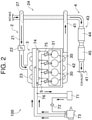
FIG. 2 is a schematic diagram illustrating an overall configuration of the engine. -
FIG. 3 is a perspective view illustrating a configuration of an engine body. -
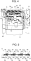
FIG. 4 is a side view illustrating the configuration of the engine body. -
FIG. 5 is a diagram illustrating the arrangement of an excess fuel return pipe as viewed in the axial direction of injectors. -
FIG. 6 is a perspective view illustrating how an injector connecting pipe is mounted on an injector. - Next, an explanation will be given of an embodiment of the present invention with reference to the drawings.
FIG. 1 is a perspective view illustrating a configuration of theengine 100 according to an embodiment of the present invention. - The
engine 100 illustrated inFIG. 1 is a diesel engine, which is to be mounted on, for example, an agricultural machine such as a tractor, a construction machine such as an excavator, etc. Theengine 100 is configured as, for example, an in-line 4-cylinder engine having four cylinders. Note that the number of cylinders is not limited to four. Theengine 100 of the present embodiment is configured with theengine body 1 and the later-describedATD 43 which is arranged on theengine body 1. - First, the basic configuration of the
engine body 1 included in theengine 100 will be explained. Note that, in the explanation below, the vertical direction of theengine 100 illustrated inFIG. 1 is referred to as the height direction. Theengine 100 has an elongated approximately rectangular shape in a plan view, and the longitudinal direction thereof is aligned with the direction in which thecrankshaft 10 extends. In the explanation below, the longitudinal direction of theengine 100 means the direction of the rotation axis of thecrankshaft 10. Further, the direction perpendicular to both of the height direction and the longitudinal direction is referred to as the width direction of theengine 100. - As illustrated in
FIG. 1 , etc., theengine body 1 is mainly configured with theoil pan 11, thecylinder block 12, thecylinder head 13, and thehead cover 14, which are arranged in order from below. - The
oil pan 11 is disposed at a lower part (lower-side end part) of theengine 100. Theoil pan 11 is formed in the shape of a container whose upper part is open. Inside theoil pan 11, engine oil for lubricating theengine 100 is stored. - The
cylinder block 12 is mounted on the upper side of theoil pan 11. A recess part for housing thecrankshaft 10, etc., which is not illustrated in the drawings, is formed in the lower part of thecylinder block 12. Although omitted inFIG. 1 , themultiple cylinders 30 are formed on the upper part of thecylinder block 12 as illustrated inFIG. 2 . The fourcylinders 30 are arranged side by side along the axial direction of thecrankshaft 10. - A piston is housed in each
cylinder 30. The piston inside acylinder 30 can move in the vertical direction. The piston is connected to thecrankshaft 10 via a connecting rod which is not illustrated in the drawings. Thecrankshaft 10 rotates as the pistons reciprocate in therespective cylinders 30. - As illustrated in
FIG. 3 , etc., thecylinder head 13 is mounted on the upper side of thecylinder block 12. Thecylinder head 13 and thecylinder block 12 form thecombustion chambers 31 illustrated inFIG. 2 corresponding to therespective cylinders 30. - The
head cover 14 is disposed on the upper side of thecylinder head 13. Inside thehead cover 14, there is housed a valve operating mechanism configured with a push rod, rocker arm, etc., which are not illustrated in the drawings, for operating an intake valve and exhaust valve, which are not illustrated in the drawings. - On one side of the longitudinal direction of the
engine 100, the coolingfan 6 for cooling the cooling water of theengine 100 is mounted in a rotatable manner. Theflywheel housing 61 which houses a flywheel, which is not illustrated in the drawings, is arranged on the other side (opposite side of the cooling fan 6) of the longitudinal direction of theengine 100. - Subsequently, focusing on the intake and exhaust flows, the configuration of the
engine 100 of the present embodiment will be briefly explained with reference toFIG. 2 , etc. - As illustrated in
FIG. 2 , theengine 100 includes theintake unit 2, thepower generation unit 3, and theexhaust unit 4 as main configurations. - The
intake unit 2 takes air in from the outside. Theintake unit 2 includes theintake pipe 21, thethrottle valve 22, theintake manifold 23, and theturbocharger 24. - The
intake pipe 21 configures an intake passage, so that the air taken in from the outside can flow to the inside. - The
throttle valve 22 is arranged in the middle part of the intake passage. Thethrottle valve 22 changes the cross-sectional area of the intake passage by changing its opened degree according to a control command from a control device which is not illustrated in the drawings. Accordingly, the amount of air supplied to theintake manifold 23 can be adjusted. - The
intake manifold 23 is connected to the downstream end part of theintake pipe 21 in the direction of the intake flow. Theintake manifold 23 distributes the air supplied via theintake pipe 21 according to the number ofcylinders 30 and supplies the air to thecombustion chambers 31 formed in therespective cylinders 30. - The
power generation unit 3 is configured with the multiple (four in the present embodiment)cylinders 30. Thepower generation unit 3 generates power to reciprocate the pistons by burning fuel in thecombustion chambers 31 formed in therespective cylinders 30. - Specifically, in each
combustion chamber 31, the air supplied from theintake manifold 23 is compressed, and then the fuel supplied from a fuel supply unit, which is not illustrated in the drawings, is injected. Accordingly, combustion occurs in thecombustion chambers 31, so that the pistons can be reciprocated up and down. The power thereby obtained is transmitted to an appropriate device on the downstream side of the power via thecrankshaft 10, etc. - The
turbocharger 24 utilizes the flow of exhaust gas discharged from thecombustion chambers 31 in order to rotate the includedcompressor 27, so that the air purified by an air cleaner, which is not illustrated in the drawings, is compressed and forcibly taken in. - The
exhaust unit 4 discharges the exhaust gas generated in thecombustion chambers 31 to the outside. Theexhaust unit 4 includes theexhaust pipe 41, theexhaust manifold 42, and theATD 43. ATD is an abbreviation for After Treatment Device. - The
exhaust pipe 41 configures an exhaust gas passage, and the exhaust gas discharged from thecombustion chambers 31 can flow to the inside thereof. - The
exhaust manifold 42 is connected to the upstream end part of theexhaust pipe 41 in the direction of the exhaust gas flow. Theexhaust manifold 42 collectively guides the exhaust gas generated in eachcombustion chamber 31 to theexhaust pipe 41. - The
ATD 43 is a device that performs post-treatment of exhaust gas. TheATD 43 purifies exhaust gas by removing harmful components such as NOx (nitrogen oxides), CO (carbon monoxide), and HC (hydrocarbons) and particulate matter (PM) contained in the exhaust gas. TheATD 43 is arranged in the middle part of theexhaust pipe 41. TheATD 43 may be supported above theengine body 1 or may be disposed separately from theengine body 1. - The
ATD 43 includes theDPF device 44 that removes carbon monoxide, nitrogen monoxide, particulate matter, and the like, which are contained in the exhaust gas, and theSCR device 45 that removes NOx contained in the exhaust gas. DPF is an abbreviation for Diesel Particulate Filter. SCR is an abbreviation for Selective Catalytic Reduction. Note that, without being limited thereto, theATD 43 may only include theDPF device 44. - Next, a configuration for supplying and injecting fuel in the
engine 100 of the present embodiment will be briefly explained. - As illustrated in
FIG. 2 , theengine 100 includes thefuel filter 72, thefuel pump 73, thecommon rail 74, theinjector 75, the excessfuel return pipe 5, and thefuel restoration pipe 76. - The
engine 100 takes in fuel from thefuel tank 71, which is for storing fuel, via thefuel pump 73. The fuel taken in by thefuel pump 73 passes through thefuel filter 72, so that dust and dirt contained in the fuel are thereby removed. Thereafter, the fuel is supplied to thecommon rail 74. Thecommon rail 74 stores fuel at high pressure and distributes the fuel to the multiple injectors 75 (four in this embodiment). - The
injectors 75 inject fuel into thecombustion chambers 31. As illustrated inFIG. 1 , theinjectors 75 are aligned along a straight line parallel to the longitudinal direction of theengine 100 and are mounted on thecylinder head 13. As illustrated inFIG. 6 , aninjector 75 is formed in an elongated approximately cylindrical shape. - The
injector 75 include a fuel injection valve, which is not illustrated in the drawings. An ECU (Engine Control Unit), which is not illustrated in the drawings but is a control device of theengine 100, is electrically connected to the fuel injection valve. The fuel injection valve opens and closes at the timing according to a signal from the ECU. Accordingly, theinjectors 75 inject fuel into thecombustion chambers 31. - As illustrated in
FIG. 1 , etc., theinjector 75 includes the signalline connecting unit 77. Theelectrical signal line 70 which transmits an instruction signal from the ECU is connected to the signalline connecting unit 77. The signalline connecting unit 77 is configured with, for example, a connector or the like. - As illustrated in
FIG. 1 andFIG. 3 , etc., the later-described excess fuel return pipe (fuel pipe) 5 is mounted on the top of eachinjector 75. The excess fuel in eachinjector 75 is collected to thefuel tank 71 via the excessfuel return pipe 5 and thefuel restoration pipe 76 which is connected to thecommon rail 74. - Subsequently, the configuration and arrangement of the excess
fuel return pipe 5 mounted on theinjectors 75 will be explained with reference toFIG. 3 through FIG. 6 .FIG. 3 is a perspective view illustrating the configuration of theengine body 1.FIG. 4 is a side view illustrating the configuration of theengine body 1.FIG. 5 is a diagram illustrating the arrangement of the excessfuel return pipe 5 viewed in the axial direction of theinjectors 75.FIG. 6 is a perspective view illustrating how theinjector connecting pipe 54 is mounted on theinjector 75. - Firstly, the configuration for mounting the excess
fuel return pipe 5 onto theinjectors 75 will be briefly explained with reference toFIG. 6 . - As illustrated in
FIG. 6 , the connectingpipe mounting unit 75a in a cylindrical shape is formed at the top of the injector 75 (at the end part opposite to the side of being inserted into the cylinder head 13). The later-describedinjector insertion unit 54b can be inserted into the connectingpipe mounting unit 75a. - The auxiliary fixing
member hooking groove 75b for hooking the later-describedauxiliary fixing member 56 is formed on the outer periphery of the connectingpipe mounting unit 75a. As illustrated inFIG. 6 , the auxiliary fixingmember hooking groove 75b is configured with a ring-shaped groove formed on the outer periphery of the connectingpipe mounting unit 75a. - As illustrated in
FIG. 5 , etc., the excessfuel return pipe 5 of the present embodiment includes the multiple injector connecting pipes (first pipes) 54 and multiple linking pipes (second pipes) 55. - As illustrated in
FIG. 5 , theinjector connecting pipes 54 are formed in an approximate S-shape when viewed in an orientation along the axial direction of theinjectors 75. Theinjector connecting pipes 54 are formed, for example, by bending a metal pipe. Theinjector connecting pipes 54 have sufficient rigidity, so that the shape thereof can be stably maintained. - The outer diameter of the
injector connecting pipes 54 is approximately the same as the inner diameter of the later-describedlinking pipes 55. Theinjector connecting pipes 54 are inserted into the linkingpipes 55 so as to be connected to the linkingpipe 55. - As illustrated in
FIG. 6 , the auxiliary fixingmember mounting groove 54a and theinjector insertion unit 54b are formed in the central part (injector connecting unit) 57 of theinjector connecting pipe 54. With this auxiliary fixingmember mounting groove 54a, the later-describedauxiliary fixing member 56 can be engaged. - The
injector insertion unit 54b is formed in a cylindrical shape extending in the axial direction of theinjector 75. Theinjector insertion unit 54b protrudes downwardly from the above-described approximate S-shaped part. When viewed in a direction perpendicular to the axial direction of theinjector 75, theinjector connecting pipe 54 is formed in an approximate T-shape. - As illustrated in
FIG. 6 , theauxiliary fixing member 56 is formed in an inverted U-shape so that the lower side thereof is open. Theauxiliary fixing member 56 has a pair of arms, and the hookingunits 56a to be hooked onto the auxiliary fixingmember hooking groove 75b of theinjector 75 are formed at the lower end of each arm. Two hookingunits 56a are arranged per arm. As illustrated inFIG. 6 , each of the hookingunits 56a has a curved shape so as to project to the central side of the auxiliary fixingmember 56. - With this configuration, the
injector connecting pipe 54 is mounted on the connectingpipe mounting unit 75a of theinjector 75 by theauxiliary fixing member 56 in a state where theinjector insertion unit 54b is inserted into the connectingpipe mounting unit 75a. - Specifically, as illustrated in
FIG. 6 , the middle part of the auxiliary fixingmember 56 is engaged with the auxiliary fixingmember mounting groove 54a of theinjector connecting pipe 54. Further, the hookingunits 56a are engaged with the auxiliary fixingmember hooking groove 75b of theinjector 75. - In this way, the hooking
units 56a of the auxiliary fixingmember 56 are hooked onto the auxiliary fixingmember hooking groove 75b, so that the position of theinjector connecting pipe 54 in the axial direction of theinjector 75 is thereby fixed. Accordingly, theinjector insertion unit 54b of theinjector connecting pipe 54 can be held so as not to slip out of theinjector 75. - Since the auxiliary fixing
member hooking groove 75b is formed in a ring shape, the hookingunits 56a of the auxiliary fixingmember 56 can move in the circumferential direction along the groove. Therefore, theinjector connecting pipe 54 is rotatable together with the auxiliary fixingmember 56 with respect to theinjector 75. - As described above, the
injector connecting pipe 54 is mounted on the connectingpipe mounting unit 75a of theinjector 75 via theauxiliary fixing member 56 in a rotatable manner with respect to theinjector 75. - Since the
injector connecting pipe 54 is mounted on the top of theinjector 75, theinjector connecting pipe 54 can be easily mounted on theinjector 75 even after theinjector 75 is mounted on thecylinder head 13. Furthermore, since theinjector connecting pipe 54 is mounted on theinjector 75 in a rotatable manner, the posture of theinjector connecting pipe 54 can be easily adjusted even after mounted on theinjector 75. - As illustrated in
FIG. 4 , when viewed in an orientation along the width direction of theengine 100, theinjector connecting pipe 54 mounted on theinjector 75 is arranged at such a position that at least a part thereof overlaps the signalline connecting unit 77 of theinjector 75. That is, theinjector connecting pipe 54 and the signalline connecting unit 77 are arranged so as to be at almost the same height. - Accordingly, the
injector connecting pipe 54 can be arranged so as to pass in the vicinity of theinjector 75. Further, compactness in the height direction of theengine 100 can be achieved. - As explained above, the four
injectors 75 of the present embodiment are arranged side by side along a straight line extending in the longitudinal direction of theengine 100. Therefore, as illustrated inFIG. 5 , each of the central parts 57 (that is, theinjector insertion units 54b) of theinjector connecting pipes 54 mounted on therespective injectors 75 is located on the same straight line L. - The
injector connecting pipe 54 has a smaller diameter than that of the later-describedlinking pipe 55, and, as illustrated inFIG. 1 andFIG. 3 , at least a part thereof is arranged so as to pass between the signalline connecting unit 77, which is included in theinjector 75, and thehead cover 14. Accordingly, since theinjector connecting pipe 54 can be arranged even in a narrow space between the signalline connecting unit 77 and thehead cover 14 while securing a large clearance between thehead cover 14 and the signalline connecting unit 77, compactness of theengine 100 can be achieved. - As illustrated in
FIG. 5 , etc., theinjector connecting pipe 54 is formed so that bothend parts central part 57 thereof are located approximately on the same line. - The linking
pipe 55 is formed of a resin material or the like and has certain elasticity. The linkingpipe 55 is formed to have a curved shape in its natural state. As illustrated inFIG. 5 , the linkingpipe 55 is formed in an approximate S-shape when viewed in an orientation along the axial direction of theinjector 75. - As illustrated in
FIG. 5 , etc., each linkingpipe 55 links twoinjector connecting pipes 54 that are adjacent to each other in a mutually-linked manner. Since the linkingpipe 55 is configured to be elastically deformable, when the linkingpipe 55 is mounted on theinjector connecting pipes 54, the linkingpipe 55 can be arranged so as to be slightly stretched or compressed from its natural state between theinjector connecting pipe 54 and theinjector connecting pipe 54. - When mounting the linking
pipe 55 onto theinjector connecting pipes 54, theinjector connecting pipes 54 are tightened from the outside with publicly-known fixing members in a state where theinjector connecting pipes 54 are inserted into the linkingpipe 55. Accordingly, the linkingpipe 55 can be fixed to theinjector connecting pipes 54. - In this way, the multiple
injector connecting pipes 54 are linked via the linkingpipes 55 so as to configure the excessfuel return pipe 5. As illustrated inFIG. 5 , this excessfuel return pipe 5 is formed in a zigzag shape with a series of S-shapes having the center on the straight line L. Further, the excessfuel return pipe 5 has such a configuration that, in the direction of the straight line L, rigid parts formed with theinjector connecting pipes 54 and elastic parts formed with the linkingpipes 55 are alternately arranged. - Accordingly, the excess
fuel return pipe 5 can be deformed so as to stretch or compress to some extent as a whole in the direction of the straight line L. As a result, when mounting the excessfuel return pipe 5 onto theinjectors 75, the positions of the respectiveinjector connecting pipes 54 can be adjusted in the direction of the straight line L, so that a mounting error (for example, an error in the mounting positions of theinjector connecting pipes 54 and the linking pipes 55) can be absorbed. Further, even if the excessfuel return pipe 5 is stretched in the direction of the straight line L, the shape thereof can be preferably maintained, so that the work for mounting can be easily performed. - Further, with the
injector connecting pipes 54 having rigidity, the shape of the excessfuel return pipe 5 can be preferably maintained, so that the clearance between the excessfuel return pipe 5 and other components arranged around the excessfuel return pipe 5 can be preferably maintained. - In the present embodiment, the linking
pipes 55 are configured to be elastically deformable. With this elastic deformation, a dimensional error, etc., of theinjector connecting pipes 54 can be absorbed, for example. - However, as explained below, the elastic deformation of the linking
pipes 55 is also used for stabilizing the path of the excessfuel return pipe 5. - Specifically, it can be explained that, in the present embodiment, before mounting the
injector connecting pipes 54 onto theinjectors 75, a subassembly is made by linking the fourinjector connecting pipes 54 to each other with the linkingpipes 55. This subassembly corresponds to the excessfuel return pipe 5. Since the work of linking theinjector connecting pipes 54 and the linkingpipes 55 can be performed in a large work space at a location away from theengine 100, the ease of assemblage is improved. - Regarding this subassembly, the interval of the
injector connecting pipes 54 is intentionally made slightly shorter than the interval of theinjectors 75, which are the assemblage counterparts. In this way, when the fourinjector connecting pipes 54 of the subassembly are respectively mounted on theinjectors 75, the linkingpipes 55 are slightly stretched between theinjector connecting pipes 54. As a result, the linkingpipes 55 can be prevented from loosing, and thus the linkingpipe 55 can be prevented from making contact with other members, etc. - In the present embodiment, the
pipe connecting units 50 are arranged side by side along the same straight line L across the three linkingpipes 55 in a state where the above-described subassembly is assembled to theengine 100. Specifically, it is said that, in the respectiveinjector connecting pipes 54, theend parts pipes 55 are located on the same straight line L as illustrated inFIG. 5 . Further, thecentral parts 57 of theinjector connecting pipes 54 are arranged so as to overlap this straight line L. - As described above, although the linking
pipes 55 are stretched when the subassembly is assembled to theengine 100, the linkingpipes 55 exert a reaction force that stretches theinjector connecting pipes 54 against it. However, theinjector connecting pipes 54 are hardly rotated by the above-described reaction force because of the layout of thepipe connecting units 50 located along the same straight line L as described above. Therefore, the positions of the linkingpipes 55 when assembled can be easily stabilized, and thus the ease of assemblage can be improved. - As explained above, the
engine 100 of the present embodiment has theengine body 1 in which thecombustion chambers 31 are formed. Thisengine 100 includes themultiple injectors 75 and the excessfuel return pipe 5. Theinjectors 75 inject fuel from thefuel tank 71 into thecombustion chambers 31. The excessfuel return pipe 5 returns the excess fuel from themultiple injectors 75 to thefuel tank 71. The excessfuel return pipe 5 includes the multipleinjector connecting pipes 54 and multiple linkingpipes 55. The linkingpipes 55 are configured with elastically deformable hoses. Each of the multipleinjector connecting pipes 54 is connected to the correspondinginjector 75. Each of the multiple linkingpipes 55 links twoinjector connecting pipes 54 that are adjacent to each other. Across the multiple linkingpipes 55, thepipe connecting units 50 with which theinjector connecting pipes 54 and the linkingpipes 55 are connected are arranged side by side along the same straight line L. - Accordingly, since a part of the excess
fuel return pipe 5 is configured with a hose that is formed to be elastically deformable, even in a case where such an assemblage method in which the excessfuel return pipe 5 is mounted onto theinjectors 75 after the excessfuel return pipe 5 is assembled in advance by connecting theinjector connecting pipes 54 and the linkingpipes 55, an assemblage error can be easily absorbed. Further, since thepipe connecting units 50 are arranged on the same straight line L across the multiple linkingpipes 55, even if the linkingpipes 55 arranged between theinjector connecting pipes 54 stretch theinjector connecting pipes 54, theinjector connecting pipes 54 are unlikely to rotate. Therefore, the shape of the excessfuel return pipe 5 can be stably maintained in the state of being assembled to theinjectors 75. - Further, in the
engine 100 of the present embodiment, theinjector connecting pipes 54 are mounted on theinjectors 75 in a rotatable manner with respect to theinjectors 75. - Accordingly, in the process of mounting the excess
fuel return pipe 5 onto theinjectors 75, the orientations of the respectiveinjector connecting pipes 54 in relation to the injectors can be changed. Therefore, the excessfuel return pipe 5 can be easily mounted on theinjectors 75. - Further, in the
engine 100 of the present embodiment, theinjector connecting pipes 54 have thecentral parts 57. Thecentral parts 57 are connected to theinjectors 75. When viewed in an orientation along the axial direction of theinjectors 75, thecentral parts 57 are positioned so as to overlap the above-described straight line L. - Accordingly, even if a reaction force in a case where the linking
pipes 55 are elastically deformed for absorbing an assemblage error or the like is applied to the first pipes, the reaction force can be received by the first pipes in a well-balanced manner. - Further, in the
engine 100 of the present embodiment, theinjector connecting pipes 54 are formed in an S-shape when viewed in an orientation along the axial direction of theinjectors 75. - Accordingly, the fuel pipes can be arranged while avoiding various surrounding members (for example, the signal
line connecting units 77 and the head cover 14). - Further, in the
engine 100 of the present embodiment, the linkingpipes 55 are configured with hoses formed to have a curved shape in its natural state. - Accordingly, the curved shaped linking
pipes 55 can be easily obtained. Further, since the linkingpipes 55 are curved from the beginning, the zigzag-shaped excessfuel return pipe 5 can be realized without excessive deformation of the linkingpipes 55. - Further, in the
engine 100 of the present embodiment, theinjectors 75 include the signalline connecting units 77 to which theelectrical signal line 70 is connected. Theinjector connecting pipes 54 and the signalline connecting units 77 are arranged so as to at least partially overlap when viewed in a direction (the width direction of the engine 100) perpendicular to both of the height direction of theengine body 1 and the crankshaft direction. - Accordingly, the
injector connecting pipes 54 and the signalline connecting units 77 can be compactly arranged as a whole. - Further, in the
engine 100 of the present embodiment, theengine body 1 includes thecylinder head 13 and thehead cover 14. Theinjectors 75 are mounted on thecylinder head 13. The head cover 14 covers thecylinder head 13. Theinjector connecting pipes 54 are arranged so as to at least partially pass between the signalline connecting units 77 and thehead cover 14. - Accordingly, the
injector connecting pipes 54 can be arranged by use of the space between the signalline connecting units 77 and thehead cover 14. Therefore, compactness of theengine 100 can be achieved. - Although the preferred embodiment of the present invention is explained above, the above-described configuration can be modified as described below, for example.
- If necessary, the shapes of the
injector connecting pipes 54 and the linkingpipes 55 can be appropriately changed. - The structure for mounting the
injector connecting pipes 54 onto theinjectors 75 is not limited to the structure explained above and can be appropriately modified. For example, it is also possible that theinjector connecting pipes 54 are fixed so as not to be rotatable with respect to theinjectors 75. - The
engine 100 of the present embodiment may be configured as a two-valve mechanism in which one throttle valve and one exhaust valve are respectively disposed or as a four-valve mechanism in which two throttle valves and two exhaust valves are respectively disposed. -
- 1 Engine body
- 5 Excess fuel return pipe (fuel pipe)
- 31 Combustion chamber
- 50 Pipe connecting unit
- 54 Injector connecting pipe (first pipe)
- 55 Linking pipe (second pipe)
- 57 Central part (injector connecting unit)
- 71 Fuel tank
- 75 Injector
- 100 Engine
Claims (7)
- An engine having an engine body in which a combustion chamber is formed, the engine comprising:a plurality of injectors to inject fuel from a fuel tank into the combustion chamber; anda fuel pipe to return excess fuel from the plurality of injectors into the fuel tank,the fuel pipe comprising:a plurality of first pipes; anda plurality of second pipes configured with hoses that are elastically deformable,wherein the plurality of first pipes are respectively connected to the corresponding injectors,
the plurality of second pipes respectively link two of the first pipes that are adjacent to each other, and
across the plurality of second pipes, pipe connecting units with which the first pipes and the second pipes are connected are arranged side by side along a same straight line. - The engine according to claim 1,
wherein the first pipes are mounted on the injectors in a rotatable manner with respect to the injectors. - The engine according to claim 1 or 2,wherein the first pipes comprise an injector connecting unit to be connected to the injectors, andwhen viewed in an orientation along an axial direction of the injectors, the injector connecting unit is located so as to overlap the straight line.
- The engine according to any one of claims 1 to 3,
wherein, when viewed in an orientation along an axial direction of the injectors, the first pipes are formed in an S-shape, and central parts of the first pipes are connected to the injectors. - The engine according to any one of claims 1 to 4,
wherein the second pipes have a curved shape in a natural state thereof. - The engine according to any one of claims 1 to 5,wherein the injectors comprise a signal line connecting unit to which an electrical signal line is connected, andwhen viewed in a direction perpendicular to both of a height direction of the engine body and a direction of a crankshaft, the first pipes and the signal line connecting unit are arranged to at least partially overlap with each other.
- The engine according to claim 6,wherein the engine body comprises a cylinder head, on which the injectors are mounted, and a head cover, which covers the cylinder head, andthe first pipes are arranged so as to at least partially pass between the signal line connecting unit and the head cover.
Applications Claiming Priority (2)
| Application Number | Priority Date | Filing Date | Title |
|---|---|---|---|
| JP2019054479A JP2020153337A (en) | 2019-03-22 | 2019-03-22 | engine |
| PCT/JP2020/009339 WO2020195666A1 (en) | 2019-03-22 | 2020-03-05 | Engine |
Publications (2)
| Publication Number | Publication Date |
|---|---|
| EP3943743A1 true EP3943743A1 (en) | 2022-01-26 |
| EP3943743A4 EP3943743A4 (en) | 2022-11-16 |
Family
ID=72558140
Family Applications (1)
| Application Number | Title | Priority Date | Filing Date |
|---|---|---|---|
| EP20776882.1A Withdrawn EP3943743A4 (en) | 2019-03-22 | 2020-03-05 | Engine |
Country Status (6)
| Country | Link |
|---|---|
| US (1) | US20220163008A1 (en) |
| EP (1) | EP3943743A4 (en) |
| JP (1) | JP2020153337A (en) |
| KR (1) | KR20210137990A (en) |
| CN (1) | CN113544377A (en) |
| WO (1) | WO2020195666A1 (en) |
Family Cites Families (10)
| Publication number | Priority date | Publication date | Assignee | Title |
|---|---|---|---|---|
| IT1284334B1 (en) * | 1996-01-23 | 1998-05-18 | Fiat Ricerche | FUEL CONTAINMENT AND COLLECTION STRUCTURE FOR A HIGH PRESSURE FUEL ENGINE INJECTION SYSTEM |
| JP3777708B2 (en) * | 1997-03-06 | 2006-05-24 | いすゞ自動車株式会社 | Injector |
| US6053149A (en) * | 1998-05-28 | 2000-04-25 | Siemens Automotive Corporation | Fuel injector clip retention arrangement |
| JP4432795B2 (en) * | 2005-02-17 | 2010-03-17 | トヨタ自動車株式会社 | Fuel supply system for diesel engines |
| JP4947083B2 (en) * | 2009-03-31 | 2012-06-06 | 株式会社デンソー | Injector connector manufacturing method |
| JP5218215B2 (en) * | 2009-03-31 | 2013-06-26 | 株式会社デンソー | connector |
| JP6091920B2 (en) | 2013-02-14 | 2017-03-08 | ヤンマー株式会社 | Fuel high pressure pipe and connection method thereof |
| FR3047434B1 (en) * | 2016-02-05 | 2018-09-07 | Delphi Technologies Ip Limited | LEAK RETURN CIRCUIT CONNECTOR |
| GB2549713A (en) * | 2016-04-25 | 2017-11-01 | Perkins Engines Co Ltd | Leak off clip for fuel injectors |
| WO2018001788A1 (en) * | 2016-06-29 | 2018-01-04 | Robert Bosch Gmbh | A backflow pipe assembly in a fuel injection system |
-
2019
- 2019-03-22 JP JP2019054479A patent/JP2020153337A/en active Pending
-
2020
- 2020-03-05 KR KR1020217023097A patent/KR20210137990A/en not_active Withdrawn
- 2020-03-05 US US17/440,890 patent/US20220163008A1/en not_active Abandoned
- 2020-03-05 WO PCT/JP2020/009339 patent/WO2020195666A1/en not_active Ceased
- 2020-03-05 EP EP20776882.1A patent/EP3943743A4/en not_active Withdrawn
- 2020-03-05 CN CN202080010160.8A patent/CN113544377A/en active Pending
Also Published As
| Publication number | Publication date |
|---|---|
| EP3943743A4 (en) | 2022-11-16 |
| US20220163008A1 (en) | 2022-05-26 |
| JP2020153337A (en) | 2020-09-24 |
| CN113544377A (en) | 2021-10-22 |
| WO2020195666A1 (en) | 2020-10-01 |
| KR20210137990A (en) | 2021-11-18 |
Similar Documents
| Publication | Publication Date | Title |
|---|---|---|
| EP2415989A1 (en) | Two-stage turbocharged engine | |
| CN101408123B (en) | Exhaust purification apparatus for engine | |
| CN102333948A (en) | Exhaust gas purification with integrated ammonia generation | |
| CN104411938B (en) | Engine device | |
| EP2527610B1 (en) | SCR catalyst section and turbocharged engine therewith | |
| US20080060352A1 (en) | System and Method for Reduction of Nitrogen Oxides from Exhaust Gases Generated by a Lean-Burn Combustion Engine | |
| US7703277B2 (en) | Exhaust gas purifying apparatus for internal combustion engine | |
| US20220163008A1 (en) | Engine | |
| US20250382909A1 (en) | Engine | |
| US9151201B2 (en) | Laser welded automotive diesel exhaust HC dosing valve | |
| US20090007551A1 (en) | Exhaust Gas Aftertreatment System | |
| CN101405487B (en) | Exhaust gas purification device for internal combustion engine | |
| JP7270014B2 (en) | engine | |
| JP5937452B2 (en) | engine | |
| US20220186645A1 (en) | Engine | |
| JP2023076532A (en) | engine | |
| KR20110104298A (en) | Mounting structure of exhaust gas aftertreatment device of agricultural work vehicle | |
| JP2014025359A (en) | Diesel engine | |
| JP2021148072A (en) | Engine system | |
| JP2014025358A (en) | Diesel engine | |
| JP2014025360A (en) | Diesel engine |
Legal Events
| Date | Code | Title | Description |
|---|---|---|---|
| STAA | Information on the status of an ep patent application or granted ep patent |
Free format text: STATUS: THE INTERNATIONAL PUBLICATION HAS BEEN MADE |
|
| PUAI | Public reference made under article 153(3) epc to a published international application that has entered the european phase |
Free format text: ORIGINAL CODE: 0009012 |
|
| STAA | Information on the status of an ep patent application or granted ep patent |
Free format text: STATUS: REQUEST FOR EXAMINATION WAS MADE |
|
| 17P | Request for examination filed |
Effective date: 20211004 |
|
| AK | Designated contracting states |
Kind code of ref document: A1 Designated state(s): AL AT BE BG CH CY CZ DE DK EE ES FI FR GB GR HR HU IE IS IT LI LT LU LV MC MK MT NL NO PL PT RO RS SE SI SK SM TR |
|
| DAV | Request for validation of the european patent (deleted) | ||
| DAX | Request for extension of the european patent (deleted) | ||
| A4 | Supplementary search report drawn up and despatched |
Effective date: 20221019 |
|
| RIC1 | Information provided on ipc code assigned before grant |
Ipc: F02M 55/00 20060101ALI20221013BHEP Ipc: F02M 37/00 20060101ALI20221013BHEP Ipc: F02M 55/02 20060101AFI20221013BHEP |
|
| STAA | Information on the status of an ep patent application or granted ep patent |
Free format text: STATUS: THE APPLICATION IS DEEMED TO BE WITHDRAWN |
|
| 18D | Application deemed to be withdrawn |
Effective date: 20230520 |