EP3943403A1 - An apparatus for applying stamps on containers for smoking articles - Google Patents
An apparatus for applying stamps on containers for smoking articles Download PDFInfo
- Publication number
- EP3943403A1 EP3943403A1 EP21182720.9A EP21182720A EP3943403A1 EP 3943403 A1 EP3943403 A1 EP 3943403A1 EP 21182720 A EP21182720 A EP 21182720A EP 3943403 A1 EP3943403 A1 EP 3943403A1
- Authority
- EP
- European Patent Office
- Prior art keywords
- container
- stamp
- folding
- unit
- containers
- Prior art date
- Legal status (The legal status is an assumption and is not a legal conclusion. Google has not performed a legal analysis and makes no representation as to the accuracy of the status listed.)
- Pending
Links
- 230000000391 smoking effect Effects 0.000 title claims abstract description 13
- 239000004831 Hot glue Substances 0.000 claims description 8
- 239000003292 glue Substances 0.000 claims description 8
- 238000000034 method Methods 0.000 claims description 5
- 238000001035 drying Methods 0.000 claims description 4
- 238000007664 blowing Methods 0.000 claims description 3
- 238000001514 detection method Methods 0.000 claims description 3
- 238000004806 packaging method and process Methods 0.000 claims description 3
- 239000002131 composite material Substances 0.000 claims description 2
- 230000002950 deficient Effects 0.000 claims description 2
- 238000011144 upstream manufacturing Methods 0.000 claims 1
- 235000019504 cigarettes Nutrition 0.000 description 10
- 239000000463 material Substances 0.000 description 3
- 241000208125 Nicotiana Species 0.000 description 2
- 235000002637 Nicotiana tabacum Nutrition 0.000 description 2
- 230000003466 anti-cipated effect Effects 0.000 description 1
- 235000019506 cigar Nutrition 0.000 description 1
- 238000004891 communication Methods 0.000 description 1
- 238000010276 construction Methods 0.000 description 1
- 230000000694 effects Effects 0.000 description 1
- 239000003571 electronic cigarette Substances 0.000 description 1
- 238000004519 manufacturing process Methods 0.000 description 1
Images

Classifications
-
- B—PERFORMING OPERATIONS; TRANSPORTING
- B65—CONVEYING; PACKING; STORING; HANDLING THIN OR FILAMENTARY MATERIAL
- B65C—LABELLING OR TAGGING MACHINES, APPARATUS, OR PROCESSES
- B65C1/00—Labelling flat essentially-rigid surfaces
- B65C1/04—Affixing labels, e.g. wrap-around labels, to two or more flat surfaces of a polyhedral article
- B65C1/042—Affixing labels, e.g. wrap-around labels, to two or more flat surfaces of a polyhedral article using two or more applicators, e.g. cooperating rollers or brushes
- B65C1/045—Affixing labels, e.g. wrap-around labels, to two or more flat surfaces of a polyhedral article using two or more applicators, e.g. cooperating rollers or brushes acting one after the other
Definitions
- the present invention relates to an apparatus for applying stamps onto containers for smoking articles, comprising:
- an apparatus of the type in question uses hot glue to fix the stamp to the container.
- a limit to the operating speed of the apparatus is constituted precisely by the time required for the hot glue to dry, to achieve a stable fixing between the stamp and the container.
- the most critical connection is that which regards the folded portion of the stamp, as this portion is capable of expressing a certain elastic return, which tends to make it detach from the container if the glue has not reached a sufficient degree of drying.
- the present invention aims to improve the indicated solution, in particular to increase its production capacity, while at the same time guaranteeing an optimal quality of the manufactured product.
- the present invention also relates to a smoking article packaging system according to claim 11, and a method for applying stamps onto containers for smoking articles according to claim 12.
- the present invention relates to an apparatus for applying stamps onto containers for smoking articles.
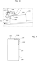
- FIG. 4 represents an example of a packet of cigarettes, indicated as a whole with the reference number 100, on which a state stamp 110 is applied.
- the stamp 110 is folded as an L, so as to identify a first portion 110A, which is applied to the upper face 102 of the packet 100, and a second portion 110B, which is fixed to the side face 104 of the packet 110.
- the two portions 110A, 110B are fixed to the two faces 102, 104, respectively, of the packet 100, by means of a layer of hot glue 105.
- the packet 100 is of the hinged cover type and comprises: a container that contains the group of cigarettes (possibly wrapped in a wrapper), wherein the group of cigarettes protrudes from an upper opening of the container; a cover that is hinged to the container and is movable between an open position, wherein it allows access to the group of cigarettes, and a closed position wherein it prevents access to the group of cigarettes.
- the apparatus described here operates to apply and fix the stamp 110 onto the packet 100 in the folded condition indicated above.
- the apparatus described here comprises a unit 20 for transporting the packets 100 according to a continuous movement along the advancing direction Y.
- the unit 20 comprises a conveyor belt which advances the packets 100 along the advancing direction Y.
- the apparatus 10 comprises, arranged in succession along the transport unit 20, a unit 40 for applying glue (preferably of the hot glue-type) onto the packets 100, a unit 60 for supplying the stamps 110, and a unit 80 for folding the stamps 110 applied onto the packets 100.
- glue preferably of the hot glue-type
- the packets 100 are arranged so as to turn the faces 102 and 104 frontally and upwards, respectively, so that they are accessible to the units 40, 60, 80 of the apparatus 10.
- the unit 40 is designed to deposit hot glue on the faces 102, 104 of the packet 100.
- This unit may be of the conventional type and use, for example, glue dot dispensing means.
- the unit 40 - or an additional fixing unit - may deposit the glue on the inner face of the stamp 110 instead of at least one of the faces 102, 104 of the packet.
- the unit 60 for supplying the stamps 110 is designed to apply the stamp on the face 104 of the packet according to an arrangement so that the stamp 110 protrudes frontally from the face 104 with a portion that will constitute the portion 110A described above.
- the portion of the stamp which instead adheres to the face 104 constitutes the portion 110B.
- the supply unit 60 may be of the conventional type.
- this unit 60 comprises a drum 62 rotating around a horizontal axis I1, with which a hopper 64 is associated, intended to contain a stack of stamps 110.
- the drum 62 picks up the individual stamps 110 in succession by means of suction means associated therewith and transfers them onto the packets 100 which pass under it.
- the unit 80 is designed to fold the protruding portion 110A of the stamp 110 against the face 102 of the packet 100.
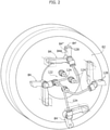
- FIG 2 illustrates an example of the folding unit 80.
- the unit 80 comprises a drum 82 rotatable around a horizontal rotation axis 12, on which a plurality of folding members 84 are mounted so that they can be operated according to a composite movement in the plane orthogonal to the rotation axis of the drum 82.
- this plane is parallel to the advancing direction Y of the transport unit 20.
- the folding member 84 is - in particular - operated according to a movement approaching the face 102, during which it intercepts the portion 110A of the stamp 110, and folds it against the same face 102, a subsequent movement wherein it accompanies the advancement of the packet along the direction Y, continuing to press the portion 110A of the stamp against the face 102, and finally a movement away from the face 102 and from the portion 110A of the stamp 110 fixed on it.
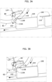
- Figures 3A, 3B , 3C illustrate these three successive steps of the operation of the folding member 84.
- the folding member 84 has an L-shaped longitudinal profile and is intended to engage the portion 110A of the stamp through its transverse end 84A.
- the folding member 84 will initially engage the portion 110A of the stamp with its face 84' ( Figure 3A ), and subsequently with the adjacent face 84" when it presses the portion 110A against the face 102 of the packet ( Figure 3B ).
- the means for actuating the members 84 may be of the conventional type, so that they will not be described in detail here in order not to make the present description more complicated.
- they can include cam means arranged to actuate the folding members 84 in the manner indicated above, by effect of the rotational movement of the drum 82.
- the folding unit 80 comprises a pneumatic system 120 arranged to blow a gas blow, preferably air, against the portion 110A of the stamp so as to press it against the face 102 of the packet.
- a gas blow preferably air
- the emitted blow is compressed air, for example at 4 bar, at room temperature.
- the pneumatic system 120 comprises a distribution module 122, mounted centrally on the drum 82 and connected to a source of compressed air - not illustrated - and a plurality of ducts 124, which connect the various folding members 84 to the distribution module 122.
- inner passages - not illustrated - are obtained in the folding members 84 which are placed in communication with the ducts 124, and lead onto the faces 84" of the members 84 through openings 128.
- the ducts 124 are preferably extendable and connected in a rotatable way to the distribution module 122 and to the folding members 84 in order to be able to follow the folding members in their movements.
- the ducts 124 are flexible and have a superabundant length, precisely to be able to follow the movements of the folding members 84.
- the blow of air delivered through the opening 128 will hit the portion 110A of the stamp to press it against the face 102 of the packet.
- the pneumatic system 120 is controlled to blow air during the approaching movement and/or the accompanying movement and/or the moving away of the folding member 84 ( Figures 3A and 3C ).
- the pneumatic system 120 is controlled to blow air during the approaching movement and the accompanying movement and the moving away of the folding member 84.
- the time in which the portion 110A of the stamp is pressed against the face 102 is lengthened, compared to the time in which the portion 110A is mechanically pressed against the face 102 by the folding member 84, during its accompanying movement.
- the apparatus 10 described here solves the technical problem discussed at the beginning of ensuring a stable fixing between the folded portion of the stamp and the corresponding face of the packet, through the combined action of the folding members 84 and the pneumatic system 120.
- This type of solution allows increasing the operating speed of the apparatus 10 and, therefore, its productivity, due to the fact that the shorter duration of the accompanying movement of the folding members 84, due to the greater speed, is compensated by the action of pressure by blowing air, of the pneumatic system 120.
- the blow of air generated by the system 120 also performs the function of accelerating the drying of the glue, which is interposed between the portion 110A and the face 102, this further reducing the cycle time necessary to fix the portion 110A to the face 102 of the packet.
- the blow of air generated by the system 120 has a predefined temperature to favor the drying of the hot glue.
- a detection unit 90 to detect the presence and/or positioning of the stamps 110 on the packets 100. In the case of absence or incorrect positioning of the stamp, discard means can intervene to remove the defective packet from the conveying line.
- the apparatus 10 described here may be integrated into a packaging system for smoking articles which has - downstream of the apparatus 10 described - a wrapping apparatus (not shown) for wrapping in outer wrappers - for example, a film made of polymeric material - the packets with the applied stamps.
- the aforementioned detection unit 90 may be arranged at the downstream wrapping apparatus.
Landscapes
- Wrapping Of Specific Fragile Articles (AREA)
- Control And Other Processes For Unpacking Of Materials (AREA)
Abstract
- a unit (20) for transporting containers (100) according to a continuous movement along an advancing direction (Y);
- a unit (60) for supplying stamps (110), which is configured to apply stamps (110) onto respective first sides (104) of the containers that are moved by the transport unit (20), according to an arrangement so that a first portion (110B) of the stamp (110) is applied to the first side (104) of the respective container, and a second portion (110A) of the stamp projects beyond the first side (104) of the container;
- a folding unit (80) configured to fold the second portion (110A) of each stamp applied on the first side (104) of the respective container against a second side (102) of the container, which is adjacent to the first side (104);
- at least one fixing unit (40) for fixing the stamp (110) and the container (100) together, particularly at the first side (104) and at the second side (102) of the container;
wherein the folding unit (80) comprises at least one folding member (84), which is movable towards the second side (102) of the container, for folding the second portion (110A) of the stamp against the second side (102) of the container, and which is movable away from the second side (102) of the container after folding the second portion (110A) of the stamp.
Description
- The present invention relates to an apparatus for applying stamps onto containers for smoking articles, comprising:
- a unit for transporting containers according to a continuous movement along an advancing direction;
- a unit for supplying stamps, which is configured to apply stamps onto respective first sides of the containers that are moved by the transport unit, according to an arrangement so that a first portion of the stamp is applied to the first side of the respective container, and a second portion of the stamp projects beyond the first side of the container;
- a folding unit configured to fold the second portion of each stamp applied on the first side of the respective container against a second side of the container, which is adjacent to the first side;
- at least one fixing unit for fixing the stamp and the container together, particularly at the first side and at the second side of the container;
- Commonly an apparatus of the type in question uses hot glue to fix the stamp to the container.
- A limit to the operating speed of the apparatus is constituted precisely by the time required for the hot glue to dry, to achieve a stable fixing between the stamp and the container.
- In this regard, the most critical connection is that which regards the folded portion of the stamp, as this portion is capable of expressing a certain elastic return, which tends to make it detach from the container if the glue has not reached a sufficient degree of drying.
- To solve the aforesaid problem, it is known to arrange the folding unit in such a way that its folding member accompanies the container for a certain distance during its movement along the advancing direction, in order to keep the folded portion of the stamp against the second side of the container, while allowing the hot glue to dry. However, this operation necessarily slows down the known type of stamp application apparatus.
- In this context, the present invention aims to improve the indicated solution, in particular to increase its production capacity, while at the same time guaranteeing an optimal quality of the manufactured product.
- The indicated object is achieved through an apparatus having the characteristics referred to in claim 1.
- The present invention also relates to a smoking article packaging system according to
claim 11, and a method for applying stamps onto containers for smoking articles according toclaim 12. - The attached claims form an integral part of the disclosure provided here.
- Further characteristics and advantages of the present invention will be provided in the following description, with reference to the attached drawings, provided purely by way of non-limiting example, wherein:
-
Figure 1 represents - in a schematic manner - a preferred embodiment of the apparatus described herein; -
Figure 2 represents an embodiment of the folding unit of the apparatus described here; -
Figures 3A to 3C represent successive steps of the operation of the folding unit ofFigure 2 ; -
Figure 4 illustrates an example of a packet of cigarettes equipped with a stamp. - In the following description, various specific details are illustrated aimed at a thorough understanding of the embodiments. The embodiments may be implemented without one or more of the specific details, or with other methods, components, materials, etc. In other cases, known structures, materials or operations are not shown or described in detail to avoid obscuring various aspects of the embodiments.
- The references used here are only for convenience and do not therefore define the field of protection or the scope of the embodiments.
- As anticipated above, the present invention relates to an apparatus for applying stamps onto containers for smoking articles.
- It should be noted that, in the present text, reference will be made indiscriminately to the specific example of "cigarettes" rather than to the more generic expression "smoking articles", without however losing generality in relation to other types of articles (such as cigars, cigarettes or cigarillos, electronic cigarettes or ecgis, "heat-not-burn" cigarettes (wherein the tobacco is heated and not burned), auxiliary products such as filters, refills for ecgis and other tobacco-based products or with alternative or tobacco-replacement components).
- An example of application of the apparatus described here concerns the application of state stamps onto cigarette packets. In this regard,
Figure 4 represents an example of a packet of cigarettes, indicated as a whole with thereference number 100, on which astate stamp 110 is applied. Thestamp 110 is folded as an L, so as to identify afirst portion 110A, which is applied to theupper face 102 of thepacket 100, and asecond portion 110B, which is fixed to theside face 104 of thepacket 110. The twoportions faces packet 100, by means of a layer of hot glue 105. - Preferably, the
packet 100 is of the hinged cover type and comprises: a container that contains the group of cigarettes (possibly wrapped in a wrapper), wherein the group of cigarettes protrudes from an upper opening of the container; a cover that is hinged to the container and is movable between an open position, wherein it allows access to the group of cigarettes, and a closed position wherein it prevents access to the group of cigarettes. - With specific reference to the example illustrated in the figures, the apparatus described here operates to apply and fix the
stamp 110 onto thepacket 100 in the folded condition indicated above. - With reference now to
Figure 1 , the apparatus described here, indicated as a whole with the reference number 10, comprises aunit 20 for transporting thepackets 100 according to a continuous movement along the advancing direction Y. In accordance with a particular embodiment, theunit 20 comprises a conveyor belt which advances thepackets 100 along the advancing direction Y. - Furthermore, the apparatus 10 comprises, arranged in succession along the
transport unit 20, aunit 40 for applying glue (preferably of the hot glue-type) onto thepackets 100, aunit 60 for supplying thestamps 110, and aunit 80 for folding thestamps 110 applied onto thepackets 100. - On the
transport unit 20, thepackets 100 are arranged so as to turn thefaces units - The
unit 40 is designed to deposit hot glue on thefaces packet 100. This unit may be of the conventional type and use, for example, glue dot dispensing means. In an alternative embodiment, the unit 40 - or an additional fixing unit - may deposit the glue on the inner face of thestamp 110 instead of at least one of thefaces - The
unit 60 for supplying thestamps 110 is designed to apply the stamp on theface 104 of the packet according to an arrangement so that thestamp 110 protrudes frontally from theface 104 with a portion that will constitute theportion 110A described above. The portion of the stamp which instead adheres to theface 104 constitutes theportion 110B. - Also in this case, the
supply unit 60 may be of the conventional type. In the example illustrated, thisunit 60 comprises adrum 62 rotating around a horizontal axis I1, with which ahopper 64 is associated, intended to contain a stack ofstamps 110. Conventionally, due to its rotational movement, thedrum 62 picks up theindividual stamps 110 in succession by means of suction means associated therewith and transfers them onto thepackets 100 which pass under it. - The
unit 80 is designed to fold the protrudingportion 110A of thestamp 110 against theface 102 of thepacket 100. -
Figure 2 illustrates an example of thefolding unit 80. According to this example, theunit 80 comprises adrum 82 rotatable around ahorizontal rotation axis 12, on which a plurality of foldingmembers 84 are mounted so that they can be operated according to a composite movement in the plane orthogonal to the rotation axis of thedrum 82. With reference toFigure 1 , it will be noted that this plane is parallel to the advancing direction Y of thetransport unit 20. - With reference to a
packet 100 in transit through thefolding unit 80, thefolding member 84 is - in particular - operated according to a movement approaching theface 102, during which it intercepts theportion 110A of thestamp 110, and folds it against thesame face 102, a subsequent movement wherein it accompanies the advancement of the packet along the direction Y, continuing to press theportion 110A of the stamp against theface 102, and finally a movement away from theface 102 and from theportion 110A of thestamp 110 fixed on it.Figures 3A, 3B ,3C illustrate these three successive steps of the operation of thefolding member 84. - In the embodiment illustrated in
Figure 2 , thefolding member 84 has an L-shaped longitudinal profile and is intended to engage theportion 110A of the stamp through itstransverse end 84A. - With reference to
Figures 3A-3C , it will be noted in particular that, during the indicated approaching movement, thefolding member 84 will initially engage theportion 110A of the stamp with its face 84' (Figure 3A ), and subsequently with theadjacent face 84" when it presses theportion 110A against theface 102 of the packet (Figure 3B ). - The means for actuating the
members 84 may be of the conventional type, so that they will not be described in detail here in order not to make the present description more complicated. By way of example, they can include cam means arranged to actuate the foldingmembers 84 in the manner indicated above, by effect of the rotational movement of thedrum 82. - According to an important characteristic of the apparatus described here, the
folding unit 80 comprises a pneumatic system 120 arranged to blow a gas blow, preferably air, against theportion 110A of the stamp so as to press it against theface 102 of the packet. Preferably, the emitted blow is compressed air, for example at 4 bar, at room temperature. - With reference to the embodiment illustrated in
Figure 2 , the pneumatic system 120 comprises adistribution module 122, mounted centrally on thedrum 82 and connected to a source of compressed air - not illustrated - and a plurality ofducts 124, which connect thevarious folding members 84 to thedistribution module 122. In addition, inner passages - not illustrated - are obtained in the foldingmembers 84 which are placed in communication with theducts 124, and lead onto thefaces 84" of themembers 84 throughopenings 128. Theducts 124 are preferably extendable and connected in a rotatable way to thedistribution module 122 and to the foldingmembers 84 in order to be able to follow the folding members in their movements. Alternatively, theducts 124 are flexible and have a superabundant length, precisely to be able to follow the movements of the foldingmembers 84. - In the operation described above of the folding
member 84, the blow of air delivered through theopening 128 will hit theportion 110A of the stamp to press it against theface 102 of the packet. - Preferably, the pneumatic system 120 is controlled to blow air during the approaching movement and/or the accompanying movement and/or the moving away of the folding member 84 (
Figures 3A and3C ). In particular, according to the preferred embodiment, the pneumatic system 120 is controlled to blow air during the approaching movement and the accompanying movement and the moving away of thefolding member 84. - In this way, the time in which the
portion 110A of the stamp is pressed against theface 102 is lengthened, compared to the time in which theportion 110A is mechanically pressed against theface 102 by thefolding member 84, during its accompanying movement. - Therefore, the apparatus 10 described here solves the technical problem discussed at the beginning of ensuring a stable fixing between the folded portion of the stamp and the corresponding face of the packet, through the combined action of the
folding members 84 and the pneumatic system 120. - This type of solution allows increasing the operating speed of the apparatus 10 and, therefore, its productivity, due to the fact that the shorter duration of the accompanying movement of the
folding members 84, due to the greater speed, is compensated by the action of pressure by blowing air, of the pneumatic system 120. - Furthermore, the blow of air generated by the system 120 also performs the function of accelerating the drying of the glue, which is interposed between the
portion 110A and theface 102, this further reducing the cycle time necessary to fix theportion 110A to theface 102 of the packet. In this regard, the blow of air generated by the system 120 has a predefined temperature to favor the drying of the hot glue. - Returning to
Figure 1 , downstream of thefolding unit 80 it is possible to provide adetection unit 90 to detect the presence and/or positioning of thestamps 110 on thepackets 100. In the case of absence or incorrect positioning of the stamp, discard means can intervene to remove the defective packet from the conveying line. - It should now be noted that the apparatus 10 described here may be integrated into a packaging system for smoking articles which has - downstream of the apparatus 10 described - a wrapping apparatus (not shown) for wrapping in outer wrappers - for example, a film made of polymeric material - the packets with the applied stamps. In this case, the
aforementioned detection unit 90 may be arranged at the downstream wrapping apparatus. - Of course, without prejudice to the principle of the invention, the details of construction and the embodiments may vary, even significantly, with respect to those illustrated here, purely by way of non-limiting example, without departing from the scope of the invention as defined by the attached claims.
Claims (12)
- An apparatus (10) for applying stamps (110) onto containers (100) for smoking articles, comprising:- a unit (20) for transporting containers (100) according to a continuous movement along an advancing direction (Y);- a unit (60) for supplying stamps (110), which is configured to apply stamps (110) onto respective first sides (104) of the containers (100) that are moved by the transport unit (20), according to an arrangement so that a first portion (110B) of the stamp (110) is applied to the first side (104) of the respective container (100), and a second portion (110A) of the stamp (110) projects beyond the first side (104) of the container (100);- a folding unit (80) configured to fold the second portion (110A) of each stamp (110) applied onto the first side (104) of the respective container (100), against a second side (102) of the container, (100), which is adjacent to the first side (104);- at least one fixing unit (40) for fixing the stamp (110) and the container (100) together, particularly at the first side (104) and at the second side (102) of the container (100);wherein the folding unit (80) comprises at least one folding member (84), which is movable towards the second side (102) of the container (100), for folding the second portion (110A) of the stamp (110) against the second side (102) of the container (100), and which is movable away from the second side (102) of the container (100) after folding the second portion (110A) of the stamp (110),
said apparatus being characterized in that said folding unit (80) comprises a pneumatic system (120) configured to blow a gas blow against the second portion (110A) of the stamp (110) so as to press the second portion (110A) against the second side (102) of the container (100). - An apparatus according to claim 1, wherein the pneumatic system (120) is configured to emit compressed air.
- An apparatus (10) according to claim 1 or 2, wherein the fixing unit (40) is configured to dispense a first fixing element, particularly glue, which is intended to fix the first portion (110B) of the stamp (110) to the first side (104) of the container (100), and a second fixing element (105), particularly glue, which is intended to fix the second portion (110A) of the stamp to the second side (102) of the container (100).
- An apparatus (10) according to claim 3, wherein said fixing unit (40) is arranged upstream of the unit (60) for supplying the stamps (110).
- An apparatus (10) according to claims 3 or 4, wherein the second fixing element (105) is hot glue, and the gas blow has a preset temperature such as to favour drying of the hot glue.
- An apparatus (10) according to any one of the previous claims,
wherein the folding member (84) can be operated according to a movement towards the second side (102) of the container (100), for folding the second portion (110A) of the stamp, an accompanying movement of the container (100) along the supplying direction (Y), for executing an action of pressing the second portion (110A) of the stamp (110) against the second side (102) of the container (100), and a movement away from the second side (102) of the container (100); and
wherein the pneumatic system (120) is configured to blow a gas blow against the second portion (110A) of the stamp (110) during the movement towards the container and/or the movement together with the container and/or the movement away from the container, of the folding member (84). - An apparatus (10) according to any one of the previous claims, wherein the folding member (84) has a face (84") which is intended to press the second portion (110A) of the stamp against the second side of the container (100), and wherein the pneumatic system (120) has an opening (128) for emitting compressed gas, which is made in said face (84"), and at least one duct which is internal to the folding member (84), for supplying compressed gas to said opening (128).
- An apparatus (10) according to any one of the preceding claims, wherein the folding unit (80) comprises a drum (82), which is rotatable about a rotation axis (12), and on which the folding member (84) is mounted so as to be driven to move according to a composite movement within a plane that is orthogonal to the rotation axis (12) of the drum (82).
- An apparatus (10) according to claim 8, wherein the folding unit (80) comprises a plurality of folding members (84) which are arranged around the rotation axis (12) of the drum (52), and wherein the pneumatic system (120) comprises a distribution module (122) and a plurality of ducts (124), which connect the distribution module (122) to the folding members (84).
- A system for packaging smoking articles, comprising:- an apparatus (10) for applying stamps (110) onto containers (100) for smoking articles, according to any one of the preceding claims;- a wrapping apparatus, which is positioned downstream of the apparatus (10) for applying stamps (110), for wrapping into outer wrappers the containers (100) on which the stamps (110) are applied, and- detection means (90), arranged in particular at the wrapping apparatus, to detect the presence and/or positioning of the stamps (110) on the containers (100),- discarding means which are positioned downstream of the detecting means (90), for discarding defective containers (100);- a control unit configured to control the discarding means as a function of signals coming from the detecting means (90).
- A method for applying stamps (110) onto containers (100) for smoking articles, comprising the steps of:- advancing containers for smoking articles in succession and according to a continuous movement, along an advancing direction (Y);- arranging the containers (100) or the stamps (110) for reciprocal fixation, particularly through applying a fixing element, preferably glue;- applying stamps (110) onto respective first sides (104) of the containers (100) so that a first portion (110B) of the stamp is fixed onto the first side (104) of the container (100), and a second portion (110A) of the stamp (110) projects beyond the first side (104);- folding the projecting second portion (110A) of each stamp that is applied on the first side (104) of the respective container (100), against a second side (102) of the container (100), which is adjacent to the first side (104);wherein the step of folding includes:- moving a folding member (84) of a folding unit (80) towards the second side (102) of the container (100), for engaging the second portion (110A) of the stamp (110) and folding it against the second side (102) of the container, and successively moving away the folding member (84) from the second side (102) of the container (100);said method being characterized in that it includes the step of blowing a gas blow onto the second portion (110A) of the stamp (100) so as to press it against the second side (102) of the container (100).
- A method according to claim 11, wherein the step of blowing is carried out during the movement towards the second side (102) or the movement away from the second side (102) of the folding member (84).
Applications Claiming Priority (1)
| Application Number | Priority Date | Filing Date | Title |
|---|---|---|---|
| IT102020000017803A IT202000017803A1 (en) | 2020-07-23 | 2020-07-23 | APPARATUS FOR APPLYING STAMPS ON CONTAINERS FOR SMOKING ITEMS |
Publications (1)
| Publication Number | Publication Date |
|---|---|
| EP3943403A1 true EP3943403A1 (en) | 2022-01-26 |
Family
ID=72709713
Family Applications (1)
| Application Number | Title | Priority Date | Filing Date |
|---|---|---|---|
| EP21182720.9A Pending EP3943403A1 (en) | 2020-07-23 | 2021-06-30 | An apparatus for applying stamps on containers for smoking articles |
Country Status (2)
| Country | Link |
|---|---|
| EP (1) | EP3943403A1 (en) |
| IT (1) | IT202000017803A1 (en) |
Citations (3)
| Publication number | Priority date | Publication date | Assignee | Title |
|---|---|---|---|---|
| US5635017A (en) * | 1995-10-30 | 1997-06-03 | Morrow; Thomas A. | Apparatus for applying closure tabs |
| EP1176098A1 (en) * | 2000-07-28 | 2002-01-30 | G.D. S.p.A. | A label application controlling device |
| EP2921414A1 (en) * | 2014-03-19 | 2015-09-23 | Focke & Co. (GmbH & Co. KG) | Device and method for manufacturing bags, in particular tobacco bags |
-
2020
- 2020-07-23 IT IT102020000017803A patent/IT202000017803A1/en unknown
-
2021
- 2021-06-30 EP EP21182720.9A patent/EP3943403A1/en active Pending
Patent Citations (3)
| Publication number | Priority date | Publication date | Assignee | Title |
|---|---|---|---|---|
| US5635017A (en) * | 1995-10-30 | 1997-06-03 | Morrow; Thomas A. | Apparatus for applying closure tabs |
| EP1176098A1 (en) * | 2000-07-28 | 2002-01-30 | G.D. S.p.A. | A label application controlling device |
| EP2921414A1 (en) * | 2014-03-19 | 2015-09-23 | Focke & Co. (GmbH & Co. KG) | Device and method for manufacturing bags, in particular tobacco bags |
Also Published As
| Publication number | Publication date |
|---|---|
| IT202000017803A1 (en) | 2022-01-23 |
Similar Documents
| Publication | Publication Date | Title |
|---|---|---|
| JP5468132B2 (en) | Wrapping method and unit for wrapping a sheet of wrapping material around a group of cigarettes | |
| US4866912A (en) | Method of an apparatus for packing rod-shaped articles of the tobacco processing industry | |
| US4845924A (en) | Process and apparatus for the packaging of paper handkerchiefs | |
| CN105431353B (en) | Method and apparatus for making packs, especially cigarette packs | |
| US8938937B2 (en) | Machine and method for packaging fiber material | |
| WO2002026563A1 (en) | Packaging material folding device of packaging machine | |
| GB1168446A (en) | Method and Apparatus for Packaging Cigarettes and Other Rod-Like Articles | |
| JP5497305B2 (en) | Method of folding paper for wrapping a group of cigarettes and wrapping unit | |
| CN113272228A (en) | Packaging machine for wrapping film around an object | |
| ITBO970698A1 (en) | DEVICE AND METHOD FOR THE APPLICATION OF REMOVABLE COUPONS IN SUBSTANTIALLY PARALLELEPIPED PACKAGES. | |
| CN107406154B (en) | Device and method for producing cuboid packs for cigarettes | |
| EP4647351A2 (en) | Cartoning machine and wrapping method to produce a carton of packs for smoking articles | |
| NL2028767B1 (en) | Device for packaging of medicine-units | |
| JPH03133712A (en) | Bottom folding packing device for packing cigaret | |
| US8256432B2 (en) | Unit and a method for wrapping tobacco products | |
| US3058275A (en) | Wrapping or packaging machines | |
| US20030205025A1 (en) | Unit for overwrapping packets | |
| EP3639680A1 (en) | Production line and method for the production of rod-shaped articles of the tobacco industry | |
| US3338026A (en) | Packaging machines | |
| US3507094A (en) | Apparatus for packing or wrapping articles | |
| CN103979131A (en) | Packaging machine and method for rigid packaging of tobacco article | |
| US6381920B1 (en) | Packaging machine with rotary wrapping assembly | |
| EP1176097B1 (en) | Device for transferring substantially parallelepiped wrappings | |
| EP4717613A1 (en) | Packer machine and wrapping method for producing a rigid pack for smoking articles with a hinged lid | |
| EP1206385A2 (en) | System and method for wrapping articles |
Legal Events
| Date | Code | Title | Description |
|---|---|---|---|
| PUAI | Public reference made under article 153(3) epc to a published international application that has entered the european phase |
Free format text: ORIGINAL CODE: 0009012 |
|
| STAA | Information on the status of an ep patent application or granted ep patent |
Free format text: STATUS: THE APPLICATION HAS BEEN PUBLISHED |
|
| AK | Designated contracting states |
Kind code of ref document: A1 Designated state(s): AL AT BE BG CH CY CZ DE DK EE ES FI FR GB GR HR HU IE IS IT LI LT LU LV MC MK MT NL NO PL PT RO RS SE SI SK SM TR |
|
| STAA | Information on the status of an ep patent application or granted ep patent |
Free format text: STATUS: REQUEST FOR EXAMINATION WAS MADE |
|
| 17P | Request for examination filed |
Effective date: 20220329 |
|
| RBV | Designated contracting states (corrected) |
Designated state(s): AL AT BE BG CH CY CZ DE DK EE ES FI FR GB GR HR HU IE IS IT LI LT LU LV MC MK MT NL NO PL PT RO RS SE SI SK SM TR |
|
| P01 | Opt-out of the competence of the unified patent court (upc) registered |
Effective date: 20230524 |