EP3943374A1 - Rear suspension device, system and method for a bicycle - Google Patents
Rear suspension device, system and method for a bicycle Download PDFInfo
- Publication number
- EP3943374A1 EP3943374A1 EP20020336.2A EP20020336A EP3943374A1 EP 3943374 A1 EP3943374 A1 EP 3943374A1 EP 20020336 A EP20020336 A EP 20020336A EP 3943374 A1 EP3943374 A1 EP 3943374A1
- Authority
- EP
- European Patent Office
- Prior art keywords
- magnet
- axis
- shock absorber
- pivot
- rotation
- Prior art date
- Legal status (The legal status is an assumption and is not a legal conclusion. Google has not performed a legal analysis and makes no representation as to the accuracy of the status listed.)
- Granted
Links
Images






Classifications
-
- B—PERFORMING OPERATIONS; TRANSPORTING
- B62—LAND VEHICLES FOR TRAVELLING OTHERWISE THAN ON RAILS
- B62J—CYCLE SADDLES OR SEATS; AUXILIARY DEVICES OR ACCESSORIES SPECIALLY ADAPTED TO CYCLES AND NOT OTHERWISE PROVIDED FOR, e.g. ARTICLE CARRIERS OR CYCLE PROTECTORS
- B62J45/00—Electrical equipment arrangements specially adapted for use as accessories on cycles, not otherwise provided for
- B62J45/40—Sensor arrangements; Mounting thereof
- B62J45/41—Sensor arrangements; Mounting thereof characterised by the type of sensor
- B62J45/413—Rotation sensors
-
- B—PERFORMING OPERATIONS; TRANSPORTING
- B62—LAND VEHICLES FOR TRAVELLING OTHERWISE THAN ON RAILS
- B62J—CYCLE SADDLES OR SEATS; AUXILIARY DEVICES OR ACCESSORIES SPECIALLY ADAPTED TO CYCLES AND NOT OTHERWISE PROVIDED FOR, e.g. ARTICLE CARRIERS OR CYCLE PROTECTORS
- B62J45/00—Electrical equipment arrangements specially adapted for use as accessories on cycles, not otherwise provided for
- B62J45/40—Sensor arrangements; Mounting thereof
- B62J45/42—Sensor arrangements; Mounting thereof characterised by mounting
-
- B—PERFORMING OPERATIONS; TRANSPORTING
- B62—LAND VEHICLES FOR TRAVELLING OTHERWISE THAN ON RAILS
- B62J—CYCLE SADDLES OR SEATS; AUXILIARY DEVICES OR ACCESSORIES SPECIALLY ADAPTED TO CYCLES AND NOT OTHERWISE PROVIDED FOR, e.g. ARTICLE CARRIERS OR CYCLE PROTECTORS
- B62J50/00—Arrangements specially adapted for use on cycles not provided for in main groups B62J1/00 - B62J45/00
- B62J50/20—Information-providing devices
- B62J50/21—Information-providing devices intended to provide information to rider or passenger
-
- B—PERFORMING OPERATIONS; TRANSPORTING
- B62—LAND VEHICLES FOR TRAVELLING OTHERWISE THAN ON RAILS
- B62K—CYCLES; CYCLE FRAMES; CYCLE STEERING DEVICES; RIDER-OPERATED TERMINAL CONTROLS SPECIALLY ADAPTED FOR CYCLES; CYCLE AXLE SUSPENSIONS; CYCLE SIDECARS, FORECARS, OR THE LIKE
- B62K25/00—Axle suspensions
- B62K25/04—Axle suspensions for mounting axles resiliently on cycle frame or fork
- B62K25/06—Axle suspensions for mounting axles resiliently on cycle frame or fork with telescopic fork, e.g. including auxiliary rocking arms
- B62K25/08—Axle suspensions for mounting axles resiliently on cycle frame or fork with telescopic fork, e.g. including auxiliary rocking arms for front wheel
-
- B—PERFORMING OPERATIONS; TRANSPORTING
- B62—LAND VEHICLES FOR TRAVELLING OTHERWISE THAN ON RAILS
- B62K—CYCLES; CYCLE FRAMES; CYCLE STEERING DEVICES; RIDER-OPERATED TERMINAL CONTROLS SPECIALLY ADAPTED FOR CYCLES; CYCLE AXLE SUSPENSIONS; CYCLE SIDECARS, FORECARS, OR THE LIKE
- B62K25/00—Axle suspensions
- B62K25/04—Axle suspensions for mounting axles resiliently on cycle frame or fork
- B62K25/28—Axle suspensions for mounting axles resiliently on cycle frame or fork with pivoted chain-stay
- B62K25/286—Axle suspensions for mounting axles resiliently on cycle frame or fork with pivoted chain-stay the shock absorber being connected to the chain-stay via a linkage mechanism
-
- G—PHYSICS
- G01—MEASURING; TESTING
- G01D—MEASURING NOT SPECIALLY ADAPTED FOR A SPECIFIC VARIABLE; ARRANGEMENTS FOR MEASURING TWO OR MORE VARIABLES NOT COVERED IN A SINGLE OTHER SUBCLASS; TARIFF METERING APPARATUS; MEASURING OR TESTING NOT OTHERWISE PROVIDED FOR
- G01D5/00—Mechanical means for transferring the output of a sensing member; Means for converting the output of a sensing member to another variable where the form or nature of the sensing member does not constrain the means for converting; Transducers not specially adapted for a specific variable
- G01D5/12—Mechanical means for transferring the output of a sensing member; Means for converting the output of a sensing member to another variable where the form or nature of the sensing member does not constrain the means for converting; Transducers not specially adapted for a specific variable using electric or magnetic means
- G01D5/14—Mechanical means for transferring the output of a sensing member; Means for converting the output of a sensing member to another variable where the form or nature of the sensing member does not constrain the means for converting; Transducers not specially adapted for a specific variable using electric or magnetic means influencing the magnitude of a current or voltage
- G01D5/142—Mechanical means for transferring the output of a sensing member; Means for converting the output of a sensing member to another variable where the form or nature of the sensing member does not constrain the means for converting; Transducers not specially adapted for a specific variable using electric or magnetic means influencing the magnitude of a current or voltage using Hall-effect devices
- G01D5/145—Mechanical means for transferring the output of a sensing member; Means for converting the output of a sensing member to another variable where the form or nature of the sensing member does not constrain the means for converting; Transducers not specially adapted for a specific variable using electric or magnetic means influencing the magnitude of a current or voltage using Hall-effect devices influenced by the relative movement between the Hall device and magnetic fields
-
- B—PERFORMING OPERATIONS; TRANSPORTING
- B62—LAND VEHICLES FOR TRAVELLING OTHERWISE THAN ON RAILS
- B62K—CYCLES; CYCLE FRAMES; CYCLE STEERING DEVICES; RIDER-OPERATED TERMINAL CONTROLS SPECIALLY ADAPTED FOR CYCLES; CYCLE AXLE SUSPENSIONS; CYCLE SIDECARS, FORECARS, OR THE LIKE
- B62K3/00—Bicycles
- B62K3/02—Frames
Definitions
- the present invention relates to the field of bicycle technology, in particular technology for, or for use with, the rear suspension of bicycles.
- Bicycles which comprise rear and/or front suspension devices require adjustment of the suspension so as to optimize sag.
- Sag is required for the wheels to conform to the contour and shape of protrusions or depressions in the terrain over which the bicycle is ridden, while at the same time providing shock absorption to the user. If the bicycle suspension has excessive sag, shock absorption will be insufficient, and conversely if the bicycle suspension has insufficient sag, loss of traction occurs.
- the present invention relates to a rear suspension device for a bicycle, wherein said device comprises:
- the present invention relates to a bicycle suspension system comprising the rear suspension device of the present invention, as described herein, in combination with a front suspension device for a bicycle and an electronic circuit, wherein said electronic circuit monitors the displacement measured by said rear suspension device and said front suspension device.
- the present invention relates to a bicycle comprising the rear suspension device of the present invention, as described herein, or the bicycle suspension system of the present invention, as described herein.
- the present invention relates to a method for classifying the first shock absorber of a rear suspension device of the present invention, as described herein, in a bicycle, as correctly or incorrectly adjusted for the user, wherein said method comprises the following steps:
- the present invention also relates to a rear suspension device for a bicycle, wherein said device comprises:
- the present invention relates to a rear suspension device for a bicycle.
- the rear suspension device when installed in a bicycle, provides suspension (shock absorption/damping) to the rear wheel of said bicycle.
- Said rear suspension device reduces the perceived impact experienced by the rider through contact of the rear wheel with protrusions/depressions in the path over which the bicycle is ridden.
- Said bicycle (bike) is preferably any type of two-wheeled vehicle, whether human-powered and/or motor-powered ( e.g . electric). More preferably, said bicycle is a mountain bicycle (MTB, mountain bike, all-terrain bicycle, off-road bicycle), a fatbike, a recumbent bicycle or a cruiser bicycle. Still more preferably, said bicycle is a mountain bicycle selected from the group consisting of a downhill bicycle, a freeride bicycle, a trail bicycle, a cross-country bicycle, an enduro bicycle, an all-mountain bicycle or a slope-style bicycle. Even more preferably, said bicycle is a mountain bicycle having wheels of an inside rim diameter of 622 mm (700C) or 584 mm (650B) according to ISO 5775-1 :1997 or ISO 5775-2:1996.
- Said rear suspension device of the present invention comprises:
- Said first axial compression shock absorber (7) is a mechanical and/or hydraulic device for absorbing or damping a load (shock force) applied thereto.
- said first axial compression shock absorber comprises a first end and a second end, a damper and a spring. Said spring compresses under load, and the damper dissipates the energy stored in the spring, thereby regulating the rate at which the spring compresses and rebounds.
- Said linkage unit (6) is a bar which links the second pivot to the third pivot.
- said linkage unit is a lever which pivots about said second axis of rotation and said third axis of rotation, wherein said axes are fulcra.
- rotational force applied to said link about said third axis of rotation is converted into an arc force (approximating a linear force) at the second axis of rotation which is applied to the first axial compression shock absorber (7).
- One embodiment of the linkage unit (6) is shown in Figure 6 .
- said rear suspension device of the present invention is preferably configured for single-pivot suspension, multiple-pivot suspension or short-link four-bar suspension.
- single-pivot suspension is selected from the group consisting of classic single-pivot suspension, linkage-driven single pivot suspension and split-pivot suspension, where there is only one pivot connecting the rear wheel to the main frame of the bicycle via a swingarm.
- multiple-pivot suspension is selected from four-bar multiple-pivot suspension or equilink multiple-pivot suspension, where there is more than one pivot connecting the rear wheel to the main frame of the bicycle.
- said multiple-pivot suspension is four-bar multiple-pivot suspension selected from the group consisting of Horst link suspension (as per the Horst Link suspension of Specialized) and FSR Suspension (as per the FSR suspension of Specialized, Cube and Scott or the Advanced Ride Technology suspension of Norco).
- said short-link four-bar suspension is selected from the group consisting of zero suspension (as per the Zero suspension system of Mondraker), virtual pivot point (VPP) suspension (as per the VPP suspension of Santa Cruz Bicycles), living link suspension (as per the Living Link suspension of Spot Bikes), DW-link suspension (as per the DW-link suspension of Ibis, Independent Fabrication, Turner Suspension Bicycles and Pivot Cycles), Maestro suspension (as per the Maestro suspension of Giant Bicycles), switch link suspension (as per the Switch link suspension of Yeti Cycles) and full floater suspension (as per the Full Floater suspension of Trek), where the rear triangle of comprising the chain-stays and seat-stays is a rigid unit that is attached to the connecting links of the short-link four-bar suspension.
- said rear suspension device of the present invention is configured for zero suspension, where the first pivot is attached to a lower linkage unit and the second pivot is attached to the linkage unit (6), such that the first axial compression shock absorber (7) floats between the two linkage units thereof and is compressed from both ends.
- Each pivot is an attachment for linking a part of said rear suspension device to another part thereof or to a part of said bicycle. Attachment may be direct, without any components between said part and said pivot, or indirect, with at least one component (e.g. a bushing or bearing) between said part and said pivot.
- each pivot is preferably also that about which rotation of a part of said rear suspension device or said bicycle is possible, depending on whether said part is able to rotate independently of said pivot or not.
- said first end of first axial compression shock absorber is attached to said first pivot and rotates about said first axis of rotation
- said second end of first axial compression shock absorber is attached to said second pivot and rotates about said second axis of rotation.
- said first end of first axial compression shock absorber is attached to said first pivot and rotates about said first axis of rotation
- said second end of first axial compression shock absorber and said linkage unit are independently attached to said second pivot and independently rotate about said second axis of rotation
- said linkage unit is attached to said third pivot and rotates about said third axis of rotation.
- said first end of the first axial compression shock absorber is attached to said first pivot and rotates about said first axis of rotation
- said second end of the first axial compression shock absorber and said linkage unit are independently attached to said second pivot and independently rotate about said second axis of rotation
- said linkage unit is attached to said third pivot and said fourth pivot and rotates about said third and fourth axes of rotation
- said bicycle frame may be also attached to said first and third pivots, and rotate about said first and third axes of rotation relative to the first axial compression shock absorber and linkage unit, respectively.
- the rotation about any given axis of rotation during use of said device may be negligible, if at all existent.
- said linkage unit (6) additionally comprises a fourth pivot (4) having a fourth axis of rotation parallel to said first axis of rotation, said second axis of rotation and said third axis of rotation, and said linkage unit is additionally attached to and rotates about said fourth pivot.
- said linkage unit is additionally attached to and rotates about said fourth pivot.
- said first sensor unit (5) comprises at least two Hall-effect sensors, more preferably four Hall-effect sensors.
- the first sensor unit is a magnetic rotary position sensor unit that is contactless insofar as each sensor measures changes in a magnetic field. By rotating the sensor unit relative to the first magnet, each sensor measures the change in the magnetic flux density which is converted to a linear output.
- the change in the magnetic flux density is measured as a change in voltage, current or resistance, preferably voltage, which can be used to calculate the relative angle of rotation.
- the first sensor unit is an AS5600 12-Bit Programmable Contactless Potentiometer furnished by ams AG which comprises four Hall-effect sensors. Said exemplified preferred embodiment of the first sensor unit (5) is shown in Figure 5 .
- said first magnet is:
- Said first magnet is attached to said third pivot, wherein the third axis of rotation and the axis of rotational symmetry of said first magnet are aligned ( Figure 4 ).
- said first magnet is attached to said second pivot, wherein the second axis of rotation and the axis of rotational symmetry of said first magnet are aligned.
- said first magnet is attached to said fourth pivot, wherein the fourth axis of rotation and the axis of rotational symmetry of said first magnet are aligned.
- the respective axis of rotation and the axis of rotational symmetry of said first magnet coincide.
- said first magnet is attached to said respective pivot so that the parallel face of said first magnet that is exposed to the first sensor unit (5) either protrudes from or is flush with an end surface of said pivot.
- said first magnet is embedded in said third pivot, and the face of said magnet which is closest to ( i.e. exposed to) said first sensor unit (5) is flush with the end surface of said third pivot.
- said first magnet is a cylindrical diametrically magnetized magnet which is embedded in a hexagonal prism-shaped cavity in the end surface of said third pivot and the parallel face of said first magnet that is exposed to the first sensor unit (5) is flush with said end surface of said third pivot.
- Each Hall-effect sensor is located in the plane perpendicular to the axis of rotation of the pivot to which it is attached ( i.e . a plane perpendicular to the axis of rotational symmetry of said first magnet) and at a distance d1 from said axis of rotation.
- said first sensor unit is located at a distance d2 from said first magnet.
- the position of the first sensor unit (5) and, thus, each Hall-effect sensor comprised therein, relative to said magnet, and, hence, the values of the parameters d1 and d2, depends on the intensity of the magnetic field of said magnet, the shape and dimensions of said magnet, the magnetic properties of objects located in the vicinity of said magnet, and the number and sensitivity of the Hall-effect sensors, amongst other parameters.
- a larger and stronger first magnet means d1 may be larger.
- the pivot to which the first magnet is attached is made of a non-ferromagnetic material.
- d1 is the same for each sensor and is between 0.1 and 50 mm, while d2 is between 0.01 mm and 50 mm.
- d1 is between 0.1 and 20 mm
- d2 is between 0.05 and 20 mm
- d2 is between 0.1 and 10 mm.
- d1 is less than or equal to the longest dimension of the parallel faces of said first magnet, and d2 is less than 5 mm.
- the rear suspension device is for a bicycle, wherein said device comprises:
- the present invention also relates to a bicycle suspension system comprising the rear suspension device, as described herein, in combination with a front suspension device for a bicycle and an electronic circuit.
- Said electronic circuit (80) is preferably a circuit comprising a processor. Changes in the magnetic flux density which are detected by the sensor units are converted into linear outputs, preferably changes in voltage. Said linear outputs are more preferably converted by said processor into an output. Said output allows the user to determine whether any given suspension device (front and/or rear) is correctly adjusted.
- Said circuit may also comprise a wireless network. Preferably said circuit is comprised in the sensor unit(s) and/or in the main board, and optionally comprises a wireless network.
- One embodiment of part of the circuit (80) is shown in the main board (8) in Figure 7 .
- Said front suspension device comprises:
- Said second axial compression shock absorber comprises a first end and a second end.
- said second axial compression shock absorber comprises the same features (but not the same dimensions) as the first axial compression shock absorber described herein.
- Said second magnet is:
- Said second sensor unit comprises a magnetic flux sensor.
- Said magnetic flux sensor is preferably a sensor selected from the group consisting of a Hall-effect sensor, a magneto-diode, a magneto-transistor, an AMR magnetometer, a GMR magnetometer, a magnetic tunnel junction magnetometer, a magneto-optical sensor, a Lorentz force based MEMS sensor, an Electron Tunneling based MEMS sensor, a MEMS compass, a nuclear precession magnetic field sensor, an optically pumped magnetic field sensor, a fluxgate magnetometer, a search coil magnetic field sensor and a SQUID magnetometer.
- said magnetic flux sensor is a Hall-effect sensor, a magneto-diode, a magneto-transistor, an AMR magnetometer or a GMR magnetometer, and the change in the magnetic flux density is measured as a change in voltage, current or resistance, preferably voltage, which is used to calculate the relative displacement of said magnetic flux sensor from said second magnet,
- said second sensor unit is an AD22151 Linear Output Magnetic Field Sensor furnished by Analog Devices, Inc.
- Said second sensor unit is located on the second end of said second shock absorber, and said second magnet is located on said first end of said second shock absorber, wherein said magnetic flux sensor and the rotational axis of symmetry of said second magnet are aligned.
- said front suspension device comprises:
- the present invention also relates to a bicycle comprising the rear suspension device of the present invention, as described herein, or the bicycle suspension system of the present invention, as described herein.
- Said bicycle may be selected from any of the aforementioned bicycles and configured with said rear suspension device or said bicycle suspension system
- the rear suspension device of the present invention when installed in a bicycle, measures the angle of rotation of the first sensor unit relative to the magnet when said rear suspension device is subject to a load. A load is applied while said bicycle is in use, in particular when the user is mounted on said bicycle. By measuring the angle of rotation in this way, it is possible to very accurately determine the distance of the path through which the rear axle of the rear wheel of the bicycle travels. Due to the diversity of rear suspension types (as mentioned above) and bicycles that are available on the market, the path (coupler curve) through which the rear axle of the rear wheel of the bicycle travels is usually a complex curve, rendering accurate measurement of the distance of the path through which the rear axle of the rear wheel of the bicycle travels very difficult. However, the rear suspension device of the present invention permits accurate measurement of this distance. Accordingly, the rear suspension device of the present invention can be used to determine whether the suspension of the bicycle is correctly adjusted for the user.
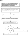
- the present invention also relates to a method for classifying the first shock absorber of a rear suspension device of the present invention, as described herein, in a bicycle, as correctly or incorrectly adjusted for the user ( Figure 9 ). Said method comprises the following steps:
- Said method may also be for classifying the first shock absorber of a rear suspension device of the present invention, as described herein, in a bicycle, as correctly or incorrectly adjusted for the user and the terrain, when steps (e) to (g) are repeated w times while moving over said terrain, to obtain w values for L which are averaged to obtain a new value for L which is either the average linear displacement, L axleav of the first shock absorber, or the linear displacement, L shockav , of the first shock absorber,
- L1 is at least 0.5% less than L2, more preferably L1 is at least 1% less than L2, even more preferably L1 is at least 2% less than L2.
- L1 is at least 0.5% less than L2, more preferably L1 is at least 1% less than L2, even more preferably L1 is at least 2% less than L2.
- steps (a) to (d) are only performed once, following installation of the rear suspension device of the present invention, as described herein, in a bicycle.
- the information obtained from these steps may be used multiple times, each time that steps (e) to (h) are repeated, for example when the user remounts the bicycle or when a different user mounts the bicycle.
- steps (e) to (h) are repeated every q hours that the user is mounted on the bicycle, wherein q is selected from 1 to 240, preferably from 2 to 72, more preferably from 3 to 12.
- steps (e) to (h) are repeated every p days, wherein p is selected from 1 to 10, preferably from 2 to 5.
- the angular displacement is measured as a function of the voltage measured in the first sensor unit.
- the angular displacement, A, of the first sensor unit with respect to the first magnet is measured when only one brake is applied.
- steps (c), (d), (f) and (g) are carried out using the electronic circuit, optionally in conjunction with a network connected wirelessly thereto.
- said electronic circuit is preferably a circuit comprising a processor. More preferably, changes in the magnetic flux density which are detected by a sensor unit are converted into a linear output (preferably changes in voltage) by said processor. Said output allows the user to determine whether any given suspension device (front and/or rear) is correctly adjusted.
- Steps (d) and (g) of converting the relative maximum angular displacement, A maxrel , into a total travel distance, T, and converting the relative angular displacement, A rel , into a linear displacement value, L, respectively, comprise a mathematical calculation.
- Said mathematical calculation may use, for example, trigonometric calculation, geometric calculation and/or calculus to convert each of said relative angular displacements into respective distances.
- Said mathematical calculation may take into account the length of the linkage unit(s) and length of the seat-stay and/or chain-stay and, where relevant, the length of the remaining rear triangle nearest to the seat tube.
- Said processor may be that of a general-purpose computer, special purpose computer, or other programmable data processing apparatus to produce a machine, such that the instructions, which execute via the processor of the circuit, create means for implementing the functions/acts specified in the flowchart and/or block diagram block or blocks.
- Said instructions may also be stored in a computer readable storage medium that can direct a processor and/or other devices to function in a particular manner, such that the computer readable storage medium having instructions stored therein comprises an article of manufacture including instructions which implement aspects of the function/act specified in the flowchart and/or block diagram block or blocks.
- the instructions may also be loaded onto a processor, a computer, other programmable data processing apparatus, or other device to cause a series of operational steps to be respectively performed on said processor, computer, other programmable apparatus or other device to produce a computer implemented process, such that the instructions which execute on the computer, other programmable apparatus, or other device implement the functions/acts specified in the flowchart and/or block diagram block or blocks.
- each block in the flowchart or block diagrams may represent a module, segment, or portion of instructions, which comprises one or more executable instructions for implementing the specified logical function(s).
- the functions noted in the block may occur out of the order noted in the Figures.
- two blocks shown in succession may, in fact, be executed substantially concurrently, or the blocks may sometimes be executed in the reverse order, depending upon the functionality involved.
- the method is additionally for classifying the second axial compression shock absorber of a front suspension device as correctly or incorrectly adjusted for the user ( Figure 10 ), wherein said method comprises the following steps:
- D rel is greater than or equal to L1' and less than or equal to L2'.
- L1' is at least 0.5% less than L2', more preferably L1' is at least 1% less than L2', even more preferably L1' is at least 2% less than L2'.
- L1' is at least 0.5% less than L2', more preferably L1' is at least 1% less than L2', even more preferably L1' is at least 2% less than L2'.
- steps (a') to (c') are only performed once, following installation of the bicycle suspension system of the present invention, as described herein, in a bicycle. More preferably, steps (a') to (c') are performed when steps (a) to (d) are performed. The information obtained from these steps may be used multiple times, each time that steps (d') to (f') are repeated. Preferably, steps (d') to (f') are repeated every time that steps (e) to (h) are repeated, as described above.
- said method informs the user accordingly.
- the user may be informed that the first shock absorber is classified as correctly adjusted for said user by, for example a light or LED of a given colour (e.g. green) or intensity, or by a display on a screen.
- the user may be informed that the first shock absorber is classified as incorrectly adjusted for said user by, for example a light or LED of a colour different to that of said given colour, or by a display on a screen.
- said method informs the user how to adjust said first shock absorber and/or said second shock absorber, respectively, wherein when:
- the user may be informed to decrease the compressibility of a given shock absorber by, for example, a light or LED of a particular colour (e.g. red), or by a display on a screen.
- the user may be informed to increase the compressibility of a given shock absorber by, for example, a light or LED of a colour (e.g. yellow) different to that of said particular colour, or by a display on a screen.
- a rear suspension device which is classified as correctly adjusted for said user is assigned a green colour
- a rear suspension device which is classified as incorrectly adjusted for said user and:
- Example 1 Rear suspension device of the present invention, located in situ in a MDFYC (Foxy Carbon) bicycle frame (cf. Figure 2).
- MDFYC Fluorescence Carbon
- the front suspension device includes a second axial compression shock absorber, a magnetic flux sensor, AD22151 (803) located in one side of the casing of the main board (7), that is aligned with a cylindrical second magnet (9), attached to one end of the second shock absorber, so that when the suspension moves axially, the relative movement between the magnet (9) and the magnetic flux sensor (803) generates a change in voltage that is detected in said sensor.
- the rear suspension device includes an first axial compression shock absorber (7) floating in a multi-pivot Zero suspension configuration that compresses it from both ends upon upward displacement of the rear axle of the bicycle relative to the frame.
- the first shock absorber (7) is attached by one end to a first pivot (1) and by the other end to a second pivot (2), each of them having an axis of rotation which is parallel to the other.
- a linkage unit (6) is also attached to said second pivot (2), as well as to a third pivot (3) which, in turn is attached to the frame of said bicycle, and a fourth pivot (4) which in turn is attached to the seat stay of the rear triangle of the bicycle.
- the first sensor unit, AS5600 (5) which is attached to the surface of the linkage unit (6), comprises a Bluetooth module, electronic devices and four Hall-effect sensors to detect the rotational movement of said first sensor unit (5) relative to the diametrically magnetized cylindrical first magnet (10) that is embedded inside a cylindrical cavity of a hexagonal bushing that in turn is inserted into the hexagonal cavity of the third pivot (3) so that the surface of said magnet that is closest to said sensor unit is flush with the end surface of said third pivot (3), wherein the distance d2 between said first sensor unit and said first magnet is less than 3 mm, and the distance d1 of the Hall-effect sensors from said third axis of rotation is less than or equal to the radius of the parallel faces of said first magnet. Said rotational movement of said first sensor unit (5) relative to the diametrically magnetized cylindrical first magnet (10) that is embedded inside a cylindrical cavity of a hexagonal bushing that in turn is inserted into the hexagonal cavity of the third pivot (3) so that the surface of said magnet that is closest to said sensor unit is
- the total travel distance, T axle of the bicycle is 153.93 mm, over which the first shock absorber travels 64.43 mm.
- Measurement of the rotational angle (relative angular displacement, A rel ) through which the first sensor unit (5) moves relative to said first magnet (10) (i.e. through which the linkage unit moves relative to the bicycle frame) was performed over this range, as shown in Table 1.
- the entries of Table 1 which are shaded grey ( ) represent those for which the first shock absorber was considered correctly adjusted for the user (indicated by a green light on a display).
- the entries above those shaded grey represent those for which the compressibility of the first shock absorber should be decreased (indicated by a red light on a display), while the entries below those shaded grey represent those for which the compressibility of the first shock absorber should be increased (indicated by a yellow light on a display).
- Example 2 Rear suspension device of the present invention, located in situ in a Crafty Carbon bicycle frame ( cf . Figure 3).
- the front suspension device includes the same second axial compression shock absorber, magnetic flux sensor, AD22151 (803), main board (7), and cylindrical second magnet (9), as in Figure 2 .
- the rear suspension device includes an first axial compression shock absorber (7) floating in a multi-pivot Zero suspension configuration that compresses it from both ends upon upward displacement of the rear axle of the bicycle relative to the frame.
- the first shock absorber (7) is attached by one end to a first pivot (1, hidden) and by the other end to a second pivot (2), each of them having an axis of rotation which is parallel to the other.
- a linkage unit (6) is also attached to said second pivot (2), as well as to a third pivot (3) which, in turn is attached to the frame of said bicycle, and a fourth pivot (4) which in turn is attached to the seat stay of the rear triangle of the bicycle.
- Said linkage unit (6) rotates about the second, third, and fourth axes of rotation upon application of a load (force) to the rear wheel of the bicycle that causes the rear axle of the bicycle to be displaced upward or downward relative to the frame.
- the first sensor unit, AS5600 (5) which is attached to the surface of the linkage unit (6) detects the rotational movement of said first sensor unit (5) relative to the diametrically magnetized cylindrical first magnet (10) that is inserted into the hexagonal cavity of the third pivot (3) so that the surface of said magnet that is closest to said sensor unit is flush with the end surface of said third pivot (3), wherein the distance d2 between said first sensor unit and said first magnet is less than 3 mm, and the distance d1 of the Hall-effect sensors of the first sensor unit (5) from said third axis of rotation is less than or equal to the radius of the parallel faces of said first magnet.
- Said rotational movement of said first sensor unit (5) relative to said first magnet (10) generates a change in voltage that is detected in said sensor.
- the total travel distance, T axle of the bicycle is 150.01 mm, over which the first shock absorber travels 65 mm. Measurement of the rotational angle (relative angular displacement, A rel ) through which the first sensor unit (5) moves relative to said first magnet (10) (i.e. through which the linkage unit moves relative to the bicycle frame) was performed over this range, as shown in Table 2.
- the entries of Table 2 which are shaded grey ( ) represent those for which the first shock absorber was considered correctly adjusted for the user (indicated by a green light on a display).
- the entries above those shaded grey represent those for which the compressibility of the first shock absorber should be decreased (indicated by a red light on a display), while the entries below those shaded grey represent those for which the compressibility of the first shock absorber should be increased (indicated by a yellow light on a display).
Landscapes
- Engineering & Computer Science (AREA)
- Mechanical Engineering (AREA)
- Physics & Mathematics (AREA)
- General Physics & Mathematics (AREA)
- Axle Suspensions And Sidecars For Cycles (AREA)
Abstract
Description
- The present invention relates to the field of bicycle technology, in particular technology for, or for use with, the rear suspension of bicycles.
- Bicycles which comprise rear and/or front suspension devices (suspension of the rear and/or front wheel, respectively) require adjustment of the suspension so as to optimize sag. Sag is required for the wheels to conform to the contour and shape of protrusions or depressions in the terrain over which the bicycle is ridden, while at the same time providing shock absorption to the user. If the bicycle suspension has excessive sag, shock absorption will be insufficient, and conversely if the bicycle suspension has insufficient sag, loss of traction occurs.
- With a view to optimizing the adjustment of the suspension sag, electronic means for measuring sag of the rear and/or front suspension have been developed.
- However, measurement of the sag is not reliable because the rear axle travels a non-linear path when a load (force) is applied thereto. Said path is at a minimum a simple arc when force is solely applied to the rear suspension system, but in bicycles which additionally comprise front suspension, or in bicycles which comprise a rear suspension system other than a classic single-pivot suspension, the path (coupler curve) through which the rear axle of the rear wheel of the bicycle travels is a complex curve, rendering accurate measurement of the distance of the path through which the rear axle of the rear wheel of the bicycle travels very difficult. This means that accurate adjustment of the suspension, and hence sag, is likewise fraught with error.
- Therefore, there is a need for means for precise measurement of the path through which the rear axle of the rear wheel of the bicycle travels and, thus, for accurately classifying a rear shock absorber as correctly or incorrectly adjusted for a user, in order that the suspension can be correctly adjusted as required.
- The present invention relates to a rear suspension device for a bicycle, wherein said device comprises:
- (a) a first pivot (1) having a first axis of rotation, a second pivot (2) having a second axis of rotation, and a third pivot (3) having a third axis of rotation;
- (b) a first axial compression shock absorber (7);
- (c) a linkage unit (6);
- (d) a first sensor unit (5); and
- (e) a first magnet (10)
wherein- said first axis of rotation, said second axis of rotation and said third axis of rotation are parallel;
- said first axial compression shock absorber comprises a first end and a second end, wherein said first end is attached to said first pivot and said second end is attached to said second pivot; and
- said linkage unit is attached to said second pivot and said third pivot and rotates about said second axis of rotation and said third axis of rotation;
characterized in that - said first sensor unit is located on a surface of said linkage unit and comprises at least one Hall-effect sensor located in a plane perpendicular to the third axis of rotation, wherein each Hall-effect sensor is located at a distance d1 from said third axis of rotation;
- said first magnet is:
- a cylindrical or cylindrical shell magnet having an axis of rotational symmetry which is perpendicular to the parallel faces thereof; or
- a prism-shaped magnet comprising two polygonal parallel faces and an axis of rotational symmetry which is perpendicular to said parallel faces;
- d1 is between 0.1 mm and 50 mm; and
- d2 is between 0.01 mm and 50 mm.
- In addition, the present invention relates to a bicycle suspension system comprising the rear suspension device of the present invention, as described herein, in combination with a front suspension device for a bicycle and an electronic circuit, wherein said electronic circuit monitors the displacement measured by said rear suspension device and said front suspension device.
- Moreover, the present invention relates to a bicycle comprising the rear suspension device of the present invention, as described herein, or the bicycle suspension system of the present invention, as described herein.
- Furthermore, the present invention relates to a method for classifying the first shock absorber of a rear suspension device of the present invention, as described herein, in a bicycle, as correctly or incorrectly adjusted for the user, wherein said method comprises the following steps:
- (a) determining the offset angle, Aoff, by measuring the angular displacement of the first sensor unit with respect to the first magnet when the first axial compression shock absorber comprised in the rear suspension device, is fully compressed;
- (b) determining the maximum angular displacement, Amax, by measuring the angular displacement of the first sensor unit with respect to the first magnet when the first shock absorber is fully extended;
- (c) determining the relative maximum angular displacement, Amaxrel, by subtracting the offset angle, Aoff, determined in step (a) from the maximum angular displacement, Amax, measured in step (b);
- (d) converting the relative maximum angular displacement, Amaxrel, into a total travel distance, T; and
- (e) measuring the angular displacement, A, of the first sensor unit with respect to the first magnet when the user is mounted on said bicycle;
- (f) determining the relative angular displacement, Arel, by subtracting the offset angle, Aoff, determined in step (a) from the angular displacement, A, measured in step (e);
- (g) converting the relative angular displacement, Arel, into a linear displacement value, L;
- (h) classifying said first shock absorber as:
- incorrectly adjusted for said user when L is less than or equal to a value L1 or greater than or equal to a value L2; or
- correctly adjusted for said user when L is between L1 and L2,
- L is the linear displacement, Laxle, of the rear axle of the bicycle;
- T is the total travel distance, Taxle, of the rear axle of the bicycle;
- L1 is a value selected from between 10% and 50% of Taxle; and
- L2 is a value selected from between 20% and 50% of Taxle,
or wherein - L is the linear displacement, Lshock, of the first shock absorber;
- T is the total travel distance, Tshock, of the first shock absorber;
- L1 is a value selected from between 10% and 50% of Tshock; and
- L2 is a value selected from between 20% and 50% of Tshock,
- The present invention also relates to a rear suspension device for a bicycle, wherein said device comprises:
- (a) a first pivot (1) having a first axis of rotation, a second pivot (2) having a second axis of rotation, and a third pivot (3) having a third axis of rotation;
- (b) a first axial compression shock absorber (7);
- (c) a linkage unit (6);
- (d) a first sensor unit (5); and
- (e) a first magnet (10)
wherein- said first axis of rotation, said second axis of rotation and said third axis of rotation are parallel;
- said first axial compression shock absorber comprises a first end and a second end, wherein said first end is attached to said first pivot and rotates about said first axis of rotation and said second end is attached to said second pivot and rotates about said second axis of rotation; and
- said linkage unit is attached to said second pivot and said third pivot and rotates about said second axis of rotation and said third axis of rotation;
characterized in that - said first sensor unit is located on a surface of said linkage unit and comprises four Hall-effect sensors located in a plane perpendicular to the third axis of rotation, wherein each Hall-effect sensor is located at a distance d1 from said third axis of rotation;
- said first magnet is a cylindrical or cylindrical shell magnet having an axis of rotational symmetry which is perpendicular to the parallel faces thereof;
wherein the direction of the magnetic moment of said first magnet is perpendicular to said axis of rotational symmetry, wherein said first magnet is attached to and embedded in said third pivot, and the face of said magnet which is closest to said first sensor unit is flush with the end surface of said third pivot;
- d1 is between 0.1 mm and 10 mm; and
- d2 is between 0.01 mm and 10 mm,
-
-
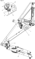
Figure 1 . Perspective view of an embodiment of a rear suspension device of the present invention, located in situ in a MDFYC (Foxy Carbon) bicycle frame, showing: first pivot (1), second pivot (2), third pivot (3), fourth pivot (4), first sensor unit (5), linkage unit (6) and first axial compression shock absorber (7). -
Figure 2 . Perspective view of an embodiment, together with exploded detail A, of a rear suspension device of the present invention, located in situ in a MDFYC (Foxy Carbon) bicycle frame, showing first pivot (1), second pivot (2), third pivot (3), fourth pivot (4), first sensor unit (5), linkage unit (6), first axial compression shock absorber (7), main board (8), housing for the second magnet (9) and first magnet (10). -
Figure 3 . Perspective view of an embodiment, together with exploded detail B, of a rear suspension device of the present invention, located in situ in a Crafty Carbon bicycle frame, showing: second pivot (2), third pivot (3), fourth pivot (4), first sensor unit (5), linkage unit (6), first axial compression shock absorber (7), main board (8), housing for the second magnet (9) and first magnet (10). -
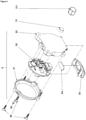
Figure 4 . Exploded perspective partial view of an embodiment of a rear suspension device of the present invention located in situ in a MDFYC (Foxy Carbon) bicycle frame showing: second pivot (2), third pivot (3), first sensor unit (5), linkage unit (6) and first magnet (10). -
Figure 5 . Exploded perspective partial view of an embodiment of a rear suspension device of the present invention showing: first sensor unit (5) and first magnet (10), as well as sensor (50), first sensor capsule cap (51), first sensor capsule base (52), first sensor USB cover (53), first sensor USB rubber (54), first sensor LED lens (55), first sensor screws (56) and first magnet housing (101). -
Figure 5 . Side view of the linkage unit (6) of an embodiment of a rear suspension device of the present invention, showing the second (2), third pivot (3) and fourth pivot (4). -
Figure 7 . Exploded perspective partial view of the main board (8) of an embodiment of the bicycle suspension system of the present invention showing: main board base capsule (81), main board cap capsule (82), main board wedge (83), main board USB cap (84), main board LED lenses (85), main board attachment means and o-rings (861 to 865) and circuit (80, partially), including the main board (801), antennae (802), fork board (803), cables (804), LED board (805) and battery (806). -
Figure 8 . Exploded perspective partial view of the second magnet (9) and associated housing of an embodiment of the bicycle suspension system of the present invention showing: second magnet capsule cap (91), second magnet capsule base (92), second magnet supplement (93), second magnet adhesive (94) and second magnet screws (95). -
Figure 9 . Flow chart of the method for classifying the first shock absorber of a rear suspension device as correctly or incorrectly adjusted for the user according to the present invention. -
Figure 10 . Flow chart of the method for classifying the second shock absorber of a front suspension device as correctly or incorrectly adjusted for the user according to the present invention. -
Figure 11 . Flow chart of the method for informing the user whether: A. the first shock absorber of a rear suspension device is correctly or incorrectly adjusted for the user or not and if not, whether to increase or decrease the compressibility of said first shock absorber in order to achieve correct adjustment, and B. the second shock absorber of a front suspension device is correctly or incorrectly adjusted for the user or not and if not, whether to increase or decrease the compressibility of said second shock absorber in order to achieve correct adjustment. - The present invention relates to a rear suspension device for a bicycle. Thus, the rear suspension device, when installed in a bicycle, provides suspension (shock absorption/damping) to the rear wheel of said bicycle. Said rear suspension device reduces the perceived impact experienced by the rider through contact of the rear wheel with protrusions/depressions in the path over which the bicycle is ridden.
- Said bicycle (bike) is preferably any type of two-wheeled vehicle, whether human-powered and/or motor-powered (e.g. electric). More preferably, said bicycle is a mountain bicycle (MTB, mountain bike, all-terrain bicycle, off-road bicycle), a fatbike, a recumbent bicycle or a cruiser bicycle. Still more preferably, said bicycle is a mountain bicycle selected from the group consisting of a downhill bicycle, a freeride bicycle, a trail bicycle, a cross-country bicycle, an enduro bicycle, an all-mountain bicycle or a slope-style bicycle. Even more preferably, said bicycle is a mountain bicycle having wheels of an inside rim diameter of 622 mm (700C) or 584 mm (650B) according to ISO 5775-1 :1997 or ISO 5775-2:1996.
- Said rear suspension device of the present invention comprises:
- (a) a first pivot (1) having a first axis of rotation, a second pivot (2) having a second axis of rotation, and a third pivot (3) having a third axis of rotation;
- (b) a first axial compression shock absorber (7);
- (c) a linkage unit (6);
- (d) a first sensor unit (5); and
- (e) a first magnet (10),
wherein:- said first axis of rotation, said second axis of rotation and said third axis of rotation are parallel;
- said first axial compression shock absorber comprises a first end and a second end, wherein said first end is attached to said first pivot and said second end is attached to said second pivot; and
- said linkage unit is attached to said second pivot and said third pivot and rotates about said second axis of rotation and said third axis of rotation.
- Said first axial compression shock absorber (7) is a mechanical and/or hydraulic device for absorbing or damping a load (shock force) applied thereto. Preferably said first axial compression shock absorber comprises a first end and a second end, a damper and a spring. Said spring compresses under load, and the damper dissipates the energy stored in the spring, thereby regulating the rate at which the spring compresses and rebounds.
- Said linkage unit (6) is a bar which links the second pivot to the third pivot. Preferably said linkage unit is a lever which pivots about said second axis of rotation and said third axis of rotation, wherein said axes are fulcra. Thus, rotational force applied to said link about said third axis of rotation is converted into an arc force (approximating a linear force) at the second axis of rotation which is applied to the first axial compression shock absorber (7). One embodiment of the linkage unit (6) is shown in
Figure 6 . - Thus, said rear suspension device of the present invention is preferably configured for single-pivot suspension, multiple-pivot suspension or short-link four-bar suspension. Preferably, single-pivot suspension is selected from the group consisting of classic single-pivot suspension, linkage-driven single pivot suspension and split-pivot suspension, where there is only one pivot connecting the rear wheel to the main frame of the bicycle via a swingarm. Preferably said multiple-pivot suspension is selected from four-bar multiple-pivot suspension or equilink multiple-pivot suspension, where there is more than one pivot connecting the rear wheel to the main frame of the bicycle. More preferably, said multiple-pivot suspension is four-bar multiple-pivot suspension selected from the group consisting of Horst link suspension (as per the Horst Link suspension of Specialized) and FSR Suspension (as per the FSR suspension of Specialized, Cube and Scott or the Advanced Ride Technology suspension of Norco). Preferably said short-link four-bar suspension is selected from the group consisting of zero suspension (as per the Zero suspension system of Mondraker), virtual pivot point (VPP) suspension (as per the VPP suspension of Santa Cruz Bicycles), living link suspension (as per the Living Link suspension of Spot Bikes), DW-link suspension (as per the DW-link suspension of Ibis, Independent Fabrication, Turner Suspension Bicycles and Pivot Cycles), Maestro suspension (as per the Maestro suspension of Giant Bicycles), switch link suspension (as per the Switch link suspension of Yeti Cycles) and full floater suspension (as per the Full Floater suspension of Trek), where the rear triangle of comprising the chain-stays and seat-stays is a rigid unit that is attached to the connecting links of the short-link four-bar suspension. Even more preferably, said rear suspension device of the present invention is configured for zero suspension, where the first pivot is attached to a lower linkage unit and the second pivot is attached to the linkage unit (6), such that the first axial compression shock absorber (7) floats between the two linkage units thereof and is compressed from both ends.
- Each pivot is an attachment for linking a part of said rear suspension device to another part thereof or to a part of said bicycle. Attachment may be direct, without any components between said part and said pivot, or indirect, with at least one component (e.g. a bushing or bearing) between said part and said pivot. By having an axis of rotation, each pivot is preferably also that about which rotation of a part of said rear suspension device or said bicycle is possible, depending on whether said part is able to rotate independently of said pivot or not. When said part is able to rotate independently of said pivot, rotation around both said pivot and its corresponding axis of rotation occurs, and when said part is not able to rotate independently of said pivot (for example, due to being immovably attached thereto), rotation around its corresponding axis of rotation occurs. Thus, in a preferred embodiment of the rear suspension device of the present invention, said first end of first axial compression shock absorber is attached to said first pivot and rotates about said first axis of rotation, and said second end of first axial compression shock absorber is attached to said second pivot and rotates about said second axis of rotation. Even more preferably, said first end of first axial compression shock absorber is attached to said first pivot and rotates about said first axis of rotation, said second end of first axial compression shock absorber and said linkage unit are independently attached to said second pivot and independently rotate about said second axis of rotation, and said linkage unit is attached to said third pivot and rotates about said third axis of rotation. Still more preferably, said first end of the first axial compression shock absorber is attached to said first pivot and rotates about said first axis of rotation, said second end of the first axial compression shock absorber and said linkage unit are independently attached to said second pivot and independently rotate about said second axis of rotation, and said linkage unit is attached to said third pivot and said fourth pivot and rotates about said third and fourth axes of rotation. In addition, said bicycle frame may be also attached to said first and third pivots, and rotate about said first and third axes of rotation relative to the first axial compression shock absorber and linkage unit, respectively. However, depending on the way in which the rear suspension device is configured, the rotation about any given axis of rotation during use of said device may be negligible, if at all existent.
- In a preferred embodiment of the rear suspension device of the present invention, said linkage unit (6) additionally comprises a fourth pivot (4) having a fourth axis of rotation parallel to said first axis of rotation, said second axis of rotation and said third axis of rotation, and said linkage unit is additionally attached to and rotates about said fourth pivot. In a more preferred embodiment of the rear suspension device of the present invention:
- said first and third pivots are for directly or indirectly attaching to the frame of said bicycle; and
- said fourth pivot is for directly or indirectly attaching to the rear wheel of said bicycle. These preferred and more preferred embodiments therefore encompass a rear suspension device which is configured for any of the aforementioned types of suspension other than classic single-pivot suspension.
- Said rear suspension device of the present invention is characterized in that
- said first sensor unit (5) is located on a surface of said linkage unit and comprises at least one Hall-effect sensor located in a plane perpendicular to the third axis of rotation, wherein each Hall-effect sensor is located at a distance d1 from said third axis of rotation;
- said first magnet is:
- a cylindrical or cylindrical shell magnet having an axis of rotational symmetry which is perpendicular to the parallel faces thereof; or
- a prism-shaped magnet comprising two polygonal parallel faces and an axis of rotational symmetry which is perpendicular to said parallel faces;
wherein the third axis of rotation and the axis of rotational symmetry of said first magnet are aligned and wherein there is a distance d2 between said first sensor unit and said first magnet, and wherein:- d1 is between 0.1 mm and 50 mm; and
- d2 is between 0.01 mm and 50 mm. Embodiments of the rear suspension device according to this configuration are shown in
Figures 1 ,2 and3 . - In an alternative embodiment:
- said first sensor unit (5) is located on a surface of said linkage unit and comprises at least one Hall-effect sensor located in a plane perpendicular to the second axis of rotation, wherein each Hall-effect sensor is located at a distance d1 from said second axis of rotation;
- said first magnet is:
- a cylindrical or cylindrical shell magnet having an axis of rotational symmetry which is perpendicular to the parallel faces thereof; or
- a prism-shaped magnet comprising two polygonal parallel faces and an axis of rotational symmetry which is perpendicular to said parallel faces;
wherein the second axis of rotation and the axis of rotational symmetry of said first magnet are aligned and wherein there is a distance d2 between said first sensor unit and said first magnet, and wherein:- d1 is between 0.1 mm and 50 mm; and
- d2 is between 0.01 mm and 50 mm.
- In another alternative embodiment:
- said first sensor unit (5) is located on a surface of said linkage unit and comprises at least one Hall-effect sensor located in a plane perpendicular to the fourth axis of rotation, wherein each Hall-effect sensor is located at a distance d1 from said fourth axis of rotation;
- said first magnet is:
- a cylindrical or cylindrical shell magnet having an axis of rotational symmetry which is perpendicular to the parallel faces thereof; or
- a prism-shaped magnet comprising two polygonal parallel faces and an axis of rotational symmetry which is perpendicular to said parallel faces;
wherein the fourth axis of rotation and the axis of rotational symmetry of said first magnet are aligned and wherein there is a distance d2 between said first sensor unit and said first magnet, and wherein:- d1 is between 0.1 mm and 50 mm; and
- d2 is between 0.01 mm and 50 mm.
- In a preferred embodiment of the present invention, said first sensor unit (5) comprises at least two Hall-effect sensors, more preferably four Hall-effect sensors. Thus, the first sensor unit is a magnetic rotary position sensor unit that is contactless insofar as each sensor measures changes in a magnetic field. By rotating the sensor unit relative to the first magnet, each sensor measures the change in the magnetic flux density which is converted to a linear output. In particular, the change in the magnetic flux density is measured as a change in voltage, current or resistance, preferably voltage, which can be used to calculate the relative angle of rotation. In an exemplified preferred embodiment of the present invention, the first sensor unit is an AS5600 12-Bit Programmable Contactless Potentiometer furnished by ams AG which comprises four Hall-effect sensors. Said exemplified preferred embodiment of the first sensor unit (5) is shown in
Figure 5 . - In the present invention, said first magnet is:
- a cylindrical or cylindrical shell (i.e. annular) magnet having an axis of rotational symmetry which is perpendicular to the parallel faces thereof; or
- a prism-shaped magnet comprising two polygonal parallel faces and an axis of rotational symmetry which is perpendicular to said parallel faces; or
- Said first magnet is attached to said third pivot, wherein the third axis of rotation and the axis of rotational symmetry of said first magnet are aligned (
Figure 4 ). Alternatively, said first magnet is attached to said second pivot, wherein the second axis of rotation and the axis of rotational symmetry of said first magnet are aligned. Alternatively, said first magnet is attached to said fourth pivot, wherein the fourth axis of rotation and the axis of rotational symmetry of said first magnet are aligned. Thus, the respective axis of rotation and the axis of rotational symmetry of said first magnet coincide. Preferably, said first magnet is attached to said respective pivot so that the parallel face of said first magnet that is exposed to the first sensor unit (5) either protrudes from or is flush with an end surface of said pivot. In a preferred embodiment of the rear suspension device of the present invention, said first magnet is embedded in said third pivot, and the face of said magnet which is closest to (i.e. exposed to) said first sensor unit (5) is flush with the end surface of said third pivot. In an exemplified even more preferred embodiment of the present invention, said first magnet is a cylindrical diametrically magnetized magnet which is embedded in a hexagonal prism-shaped cavity in the end surface of said third pivot and the parallel face of said first magnet that is exposed to the first sensor unit (5) is flush with said end surface of said third pivot. - Each Hall-effect sensor is located in the plane perpendicular to the axis of rotation of the pivot to which it is attached (i.e. a plane perpendicular to the axis of rotational symmetry of said first magnet) and at a distance d1 from said axis of rotation. In addition, said first sensor unit is located at a distance d2 from said first magnet. The skilled person will understand that the position of the first sensor unit (5) and, thus, each Hall-effect sensor comprised therein, relative to said magnet, and, hence, the values of the parameters d1 and d2, depends on the intensity of the magnetic field of said magnet, the shape and dimensions of said magnet, the magnetic properties of objects located in the vicinity of said magnet, and the number and sensitivity of the Hall-effect sensors, amongst other parameters. For example, a larger and stronger first magnet means d1 may be larger. In a particularly preferred embodiment, the pivot to which the first magnet is attached is made of a non-ferromagnetic material.
- In the present invention, d1 is the same for each sensor and is between 0.1 and 50 mm, while d2 is between 0.01 mm and 50 mm. Preferably, d1 is between 0.1 and 20 mm, and d2 is between 0.05 and 20 mm, more preferably d1 is between 0.15 and 10 mm, and d2 is between 0.1 and 10 mm. In a preferred embodiment of the rear suspension device of the present invention, d1 is less than or equal to the longest dimension of the parallel faces of said first magnet, and d2 is less than 5 mm.
- In a particularly preferred embodiment of the present invention, the rear suspension device is for a bicycle, wherein said device comprises:
- (a) a first pivot (1) having a first axis of rotation, a second pivot (2) having a second axis of rotation, and a third pivot (3) having a third axis of rotation;
- (b) a first axial compression shock absorber (7);
- (c) a linkage unit (6);
- (d) a first sensor unit (5); and
- (e) a first magnet (10)
wherein- said first axis of rotation, said second axis of rotation and said third axis of rotation are parallel;
- said first axial compression shock absorber comprises a first end and a second end, wherein said first end is attached to said first pivot and rotates about said first axis of rotation and said second end is attached to said second pivot and rotates about said second axis of rotation; and
- said linkage unit is attached to said second pivot and said third pivot and rotates about said second axis of rotation and said third axis of rotation;
characterized in that - said first sensor unit is located on a surface of said linkage unit and comprises four Hall-effect sensors located in a plane perpendicular to the third axis of rotation, wherein each Hall-effect sensor is located at a distance d1 from said third axis of rotation;
- said first magnet is a cylindrical or cylindrical shell magnet having an axis of rotational symmetry which is perpendicular to the parallel faces thereof;
wherein the direction of the magnetic moment of said first magnet is perpendicular to said axis of rotational symmetry, wherein said first magnet is attached to said third pivot;
- d1 is between 0.1 mm and 10 mm; and
- d2 is between 0.01 mm and 10 mm,
- The present invention also relates to a bicycle suspension system comprising the rear suspension device, as described herein, in combination with a front suspension device for a bicycle and an electronic circuit.
- Said electronic circuit (80) is preferably a circuit comprising a processor. Changes in the magnetic flux density which are detected by the sensor units are converted into linear outputs, preferably changes in voltage. Said linear outputs are more preferably converted by said processor into an output. Said output allows the user to determine whether any given suspension device (front and/or rear) is correctly adjusted. Said circuit may also comprise a wireless network. Preferably said circuit is comprised in the sensor unit(s) and/or in the main board, and optionally comprises a wireless network. One embodiment of part of the circuit (80) is shown in the main board (8) in
Figure 7 . - Said front suspension device comprises:
- (a) a second axial compression shock absorber;
- (b) a second sensor unit; and
- (c) a second magnet.
- Said second axial compression shock absorber comprises a first end and a second end. Preferably, said second axial compression shock absorber comprises the same features (but not the same dimensions) as the first axial compression shock absorber described herein.
- Said second magnet is:
- a cylindrical magnet having a rotational axis of symmetry which is perpendicular to the parallel faces thereof; or
- a prism-shaped magnet comprising two polygonal parallel faces and an axis of rotational symmetry which is perpendicular to said parallel faces;
- Said second sensor unit comprises a magnetic flux sensor. Said magnetic flux sensor is preferably a sensor selected from the group consisting of a Hall-effect sensor, a magneto-diode, a magneto-transistor, an AMR magnetometer, a GMR magnetometer, a magnetic tunnel junction magnetometer, a magneto-optical sensor, a Lorentz force based MEMS sensor, an Electron Tunneling based MEMS sensor, a MEMS compass, a nuclear precession magnetic field sensor, an optically pumped magnetic field sensor, a fluxgate magnetometer, a search coil magnetic field sensor and a SQUID magnetometer. More preferably, said magnetic flux sensor is a Hall-effect sensor, a magneto-diode, a magneto-transistor, an AMR magnetometer or a GMR magnetometer, and the change in the magnetic flux density is measured as a change in voltage, current or resistance, preferably voltage, which is used to calculate the relative displacement of said magnetic flux sensor from said second magnet, In an exemplified preferred embodiment of the present invention, said second sensor unit is an AD22151 Linear Output Magnetic Field Sensor furnished by Analog Devices, Inc.
- Said second sensor unit is located on the second end of said second shock absorber, and said second magnet is located on said first end of said second shock absorber, wherein said magnetic flux sensor and the rotational axis of symmetry of said second magnet are aligned.
- Thus, in a preferred embodiment of the bicycle suspension system of the present invention, said front suspension device comprises:
- (a) a second axial compression shock absorber;
- (b) a second sensor unit; and
- (c) a second magnet, wherein
- said second axial compression shock absorber comprises a first end and a second end;
- said second magnet is:
- a cylindrical magnet having a rotational axis of symmetry which is perpendicular to the parallel faces thereof; or
- a prism-shaped magnet comprising two polygonal parallel faces and an axis of rotational symmetry which is perpendicular to said parallel faces;
- said second sensor unit comprises a magnetic flux sensor located on the second end of said second shock absorber,
- The present invention also relates to a bicycle comprising the rear suspension device of the present invention, as described herein, or the bicycle suspension system of the present invention, as described herein. Said bicycle may be selected from any of the aforementioned bicycles and configured with said rear suspension device or said bicycle suspension system
- The rear suspension device of the present invention, as described herein, when installed in a bicycle, measures the angle of rotation of the first sensor unit relative to the magnet when said rear suspension device is subject to a load. A load is applied while said bicycle is in use, in particular when the user is mounted on said bicycle. By measuring the angle of rotation in this way, it is possible to very accurately determine the distance of the path through which the rear axle of the rear wheel of the bicycle travels. Due to the diversity of rear suspension types (as mentioned above) and bicycles that are available on the market, the path (coupler curve) through which the rear axle of the rear wheel of the bicycle travels is usually a complex curve, rendering accurate measurement of the distance of the path through which the rear axle of the rear wheel of the bicycle travels very difficult. However, the rear suspension device of the present invention permits accurate measurement of this distance. Accordingly, the rear suspension device of the present invention can be used to determine whether the suspension of the bicycle is correctly adjusted for the user.
- Thus, the present invention also relates to a method for classifying the first shock absorber of a rear suspension device of the present invention, as described herein, in a bicycle, as correctly or incorrectly adjusted for the user (
Figure 9 ). Said method comprises the following steps: - (a) determining the offset angle, Aoff, by measuring the angular displacement of the first sensor unit with respect to the first magnet when the first axial compression shock absorber comprised in the rear suspension device, is fully compressed;
- (b) determining the maximum angular displacement, Amax, by measuring the angular displacement of the first sensor unit with respect to the first magnet when the first shock absorber is fully extended;
- (c) determining the relative maximum angular displacement, Amaxrel, by subtracting the offset angle, Aoff, determined in step (a) from the maximum angular displacement, Amax, measured in step (b);
- (d) converting the relative maximum angular displacement, Amaxrel, into a total travel distance, T; and
- (e) measuring the angular displacement, A, of the first sensor unit with respect to the first magnet when the user is mounted on said bicycle;
- (f) determining the relative angular displacement, Arel, by subtracting the offset angle, Aoff, determined in step (a) from the angular displacement, A, measured in step (e);
- (g) converting the relative angular displacement, Arel, into a linear displacement value, L;
- (h) classifying said first shock absorber as:
- incorrectly adjusted for said user when L is less than a value L1 or greater than a value L2; or
- correctly adjusted for said user when L is between L1 and L2,
- L is the linear displacement, Laxle, of the rear axle of the bicycle;
- T is the total travel distance, Taxle, of the rear axle of the bicycle;
- L1 is a value selected from between 10% and 50% of Taxle; and
- L2 is a value selected from between 20% and 50% of Taxle,
or wherein - L is the linear displacement, Lshock, of the first shock absorber;
- T is the total travel distance, Tshock, of the first shock absorber;
- L1 is a value selected from between 10% and 50% of Tshock; and
- L2 is a value selected from between 20% and 50% of Tshock,
- Said method may also be for classifying the first shock absorber of a rear suspension device of the present invention, as described herein, in a bicycle, as correctly or incorrectly adjusted for the user and the terrain, when steps (e) to (g) are repeated w times while moving over said terrain, to obtain w values for L which are averaged to obtain a new value for L which is either the average linear displacement, Laxleav of the first shock absorber, or the linear displacement, Lshockav, of the first shock absorber,
- When L is between L1 and L2, L is greater than or equal to L1 and less than or equal to L2. Preferably, L1 is at least 0.5% less than L2, more preferably L1 is at least 1% less than L2, even more preferably L1 is at least 2% less than L2. In a preferred embodiment of the method of the present invention:
- L is the linear displacement, Laxle, of the rear axle of the bicycle;
- T is the total travel distance, Taxle, of the rear axle of the bicycle;
- L1 is a value selected from between 20% and 34% of Taxle; and
- L2 is a value selected from between 21% and 35% of Taxle,
- L is the linear displacement, Lshock, of the first shock absorber;
- T is the total travel distance, Tshock, of the first shock absorber;
- L1 is a value selected from between 20% and 34% of Tshock; and
- L2 is a value selected from between 21% and 35% of Tshock,
- Preferably, steps (a) to (d) are only performed once, following installation of the rear suspension device of the present invention, as described herein, in a bicycle. The information obtained from these steps may be used multiple times, each time that steps (e) to (h) are repeated, for example when the user remounts the bicycle or when a different user mounts the bicycle. More preferably, steps (e) to (h) are repeated every q hours that the user is mounted on the bicycle, wherein q is selected from 1 to 240, preferably from 2 to 72, more preferably from 3 to 12. Even more preferably, steps (e) to (h) are repeated every p days, wherein p is selected from 1 to 10, preferably from 2 to 5.
- In a preferred embodiment of the method of the present invention, the angular displacement is measured as a function of the voltage measured in the first sensor unit. In another more preferred embodiment of the method of the present invention, the angular displacement, A, of the first sensor unit with respect to the first magnet is measured when only one brake is applied.
- In a preferred embodiment of the method of the present invention, steps (c), (d), (f) and (g) are carried out using the electronic circuit, optionally in conjunction with a network connected wirelessly thereto. As mentioned above, said electronic circuit is preferably a circuit comprising a processor. More preferably, changes in the magnetic flux density which are detected by a sensor unit are converted into a linear output (preferably changes in voltage) by said processor. Said output allows the user to determine whether any given suspension device (front and/or rear) is correctly adjusted.
- Steps (d) and (g) of converting the relative maximum angular displacement, Amaxrel, into a total travel distance, T, and converting the relative angular displacement, Arel, into a linear displacement value, L, respectively, comprise a mathematical calculation. Said mathematical calculation may use, for example, trigonometric calculation, geometric calculation and/or calculus to convert each of said relative angular displacements into respective distances. Said mathematical calculation may take into account the length of the linkage unit(s) and length of the seat-stay and/or chain-stay and, where relevant, the length of the remaining rear triangle nearest to the seat tube.
- Said processor may be that of a general-purpose computer, special purpose computer, or other programmable data processing apparatus to produce a machine, such that the instructions, which execute via the processor of the circuit, create means for implementing the functions/acts specified in the flowchart and/or block diagram block or blocks. Said instructions may also be stored in a computer readable storage medium that can direct a processor and/or other devices to function in a particular manner, such that the computer readable storage medium having instructions stored therein comprises an article of manufacture including instructions which implement aspects of the function/act specified in the flowchart and/or block diagram block or blocks.
- The instructions may also be loaded onto a processor, a computer, other programmable data processing apparatus, or other device to cause a series of operational steps to be respectively performed on said processor, computer, other programmable apparatus or other device to produce a computer implemented process, such that the instructions which execute on the computer, other programmable apparatus, or other device implement the functions/acts specified in the flowchart and/or block diagram block or blocks.
- The flowchart and block diagrams in the Figures illustrate the architecture, functionality, and operation of possible implementations of the device, system and method according to various embodiments of the present invention. In this regard, each block in the flowchart or block diagrams may represent a module, segment, or portion of instructions, which comprises one or more executable instructions for implementing the specified logical function(s). In some alternative implementations, the functions noted in the block may occur out of the order noted in the Figures. For example, two blocks shown in succession may, in fact, be executed substantially concurrently, or the blocks may sometimes be executed in the reverse order, depending upon the functionality involved. It will also be noted that each block of the block diagrams and/or flowchart illustration, and combinations of blocks in the block diagrams and/or flowchart illustration, can be implemented by special purpose hardware-based systems that perform the specified functions or acts or carry out combinations of special purpose hardware and computer instructions.
- In a preferred embodiment of the method of the present invention, the method is additionally for classifying the second axial compression shock absorber of a front suspension device as correctly or incorrectly adjusted for the user (
Figure 10 ), wherein said method comprises the following steps: - (a') determining the offset distance, Doff, by measuring the displacement of the second sensor unit with respect to the second magnet when the second axial compression shock absorber comprised in the front suspension device, is fully compressed;
- (b') determining the maximum displacement, Dmax, by measuring the displacement of the second sensor unit with respect to the second magnet when the second shock absorber is fully extended;
- (c') determining the relative maximum displacement, Dmaxrel, by subtracting the offset distance, Doff, determined in step (a') from the maximum displacement, Dmax, measured in step (b');
- (d') measuring the displacement, D, of the second sensor unit with respect to the second magnet when the user is mounted on said bicycle;
- (e') determining the relative displacement, Drel, by subtracting the offset distance, Doff, determined in step (a') from the displacement, D, measured in step (d');
- (f') classifying said second shock absorber as:
- incorrectly adjusted for said user when Drel is less than a value L1' or greater than a value L2'; or
- correctly adjusted for said user when Drel is between L1' and L2',
- L1' is a value selected from between 10% and 50% of Dmaxrel; and
- L2' is a value selected from between 20% and 50% of Dmaxrel,
- When Drel is between L1' and L2', Drel is greater than or equal to L1' and less than or equal to L2'. Preferably, L1' is at least 0.5% less than L2', more preferably L1' is at least 1% less than L2', even more preferably L1' is at least 2% less than L2'. In a preferred embodiment of the method of the present invention:
- L1' is a value selected from between 20% and 39% of Dmaxrel; and
- L2' is a value selected from between 21% and 40% of Dmaxrel.
- Preferably, steps (a') to (c') are only performed once, following installation of the bicycle suspension system of the present invention, as described herein, in a bicycle. More preferably, steps (a') to (c') are performed when steps (a) to (d) are performed. The information obtained from these steps may be used multiple times, each time that steps (d') to (f') are repeated. Preferably, steps (d') to (f') are repeated every time that steps (e) to (h) are repeated, as described above.
- Preferably, when said first shock absorber and/or said second shock absorber is correctly or incorrectly adjusted for the user, said method informs the user accordingly. The user may be informed that the first shock absorber is classified as correctly adjusted for said user by, for example a light or LED of a given colour (e.g. green) or intensity, or by a display on a screen. Similarly, the user may be informed that the first shock absorber is classified as incorrectly adjusted for said user by, for example a light or LED of a colour different to that of said given colour, or by a display on a screen.
- In a preferred embodiment of the method of the present invention, when said first shock absorber and/or said second shock absorber is incorrectly adjusted for the user, said method informs the user how to adjust said first shock absorber and/or said second shock absorber, respectively, wherein when:
- L is less than L1, the user is informed to decrease the compressibility of the first shock absorber (
Figure 11A ); - L is greater than L2, the user is informed to increase the compressibility of the first shock absorber (
Figure 11A ); - Drel is less than L1', the user is informed to decrease the compressibility of the second shock absorber (
Figure 11B ); and/or - Drel is greater than L2', the user is informed to increase the compressibility of the second shock absorber (
Figure 11B ). - The user may be informed to decrease the compressibility of a given shock absorber by, for example, a light or LED of a particular colour (e.g. red), or by a display on a screen. Similarly, the user may be informed to increase the compressibility of a given shock absorber by, for example, a light or LED of a colour (e.g. yellow) different to that of said particular colour, or by a display on a screen. In the examples below, a rear suspension device which is classified as correctly adjusted for said user is assigned a green colour, while a rear suspension device which is classified as incorrectly adjusted for said user and:
- for which the user is informed to decrease the compressibility of the first shock absorber is assigned a red colour; and
- for which the user is informed to increase the compressibility of the first shock absorber is assigned a yellow colour.
- In
Figure 2 , the front suspension device includes a second axial compression shock absorber, a magnetic flux sensor, AD22151 (803) located in one side of the casing of the main board (7), that is aligned with a cylindrical second magnet (9), attached to one end of the second shock absorber, so that when the suspension moves axially, the relative movement between the magnet (9) and the magnetic flux sensor (803) generates a change in voltage that is detected in said sensor. - In
Figure 2 , the rear suspension device includes an first axial compression shock absorber (7) floating in a multi-pivot Zero suspension configuration that compresses it from both ends upon upward displacement of the rear axle of the bicycle relative to the frame. The first shock absorber (7) is attached by one end to a first pivot (1) and by the other end to a second pivot (2), each of them having an axis of rotation which is parallel to the other. A linkage unit (6) is also attached to said second pivot (2), as well as to a third pivot (3) which, in turn is attached to the frame of said bicycle, and a fourth pivot (4) which in turn is attached to the seat stay of the rear triangle of the bicycle. Said linkage unit (6) rotates about the second, third, and fourth axes of rotation upon application of a load (force) to the rear wheel of the bicycle that causes the rear axle of the bicycle to be displaced upward or downward relative to the frame. The first sensor unit, AS5600 (5), which is attached to the surface of the linkage unit (6), comprises a Bluetooth module, electronic devices and four Hall-effect sensors to detect the rotational movement of said first sensor unit (5) relative to the diametrically magnetized cylindrical first magnet (10) that is embedded inside a cylindrical cavity of a hexagonal bushing that in turn is inserted into the hexagonal cavity of the third pivot (3) so that the surface of said magnet that is closest to said sensor unit is flush with the end surface of said third pivot (3), wherein the distance d2 between said first sensor unit and said first magnet is less than 3 mm, and the distance d1 of the Hall-effect sensors from said third axis of rotation is less than or equal to the radius of the parallel faces of said first magnet. Said rotational movement of said first sensor unit (5) relative to said first magnet (10) generates a change in voltage that is detected in said sensor. - The total travel distance, Taxle of the bicycle is 153.93 mm, over which the first shock absorber travels 64.43 mm. Measurement of the rotational angle (relative angular displacement, Arel) through which the first sensor unit (5) moves relative to said first magnet (10) (i.e. through which the linkage unit moves relative to the bicycle frame) was performed over this range, as shown in Table 1.
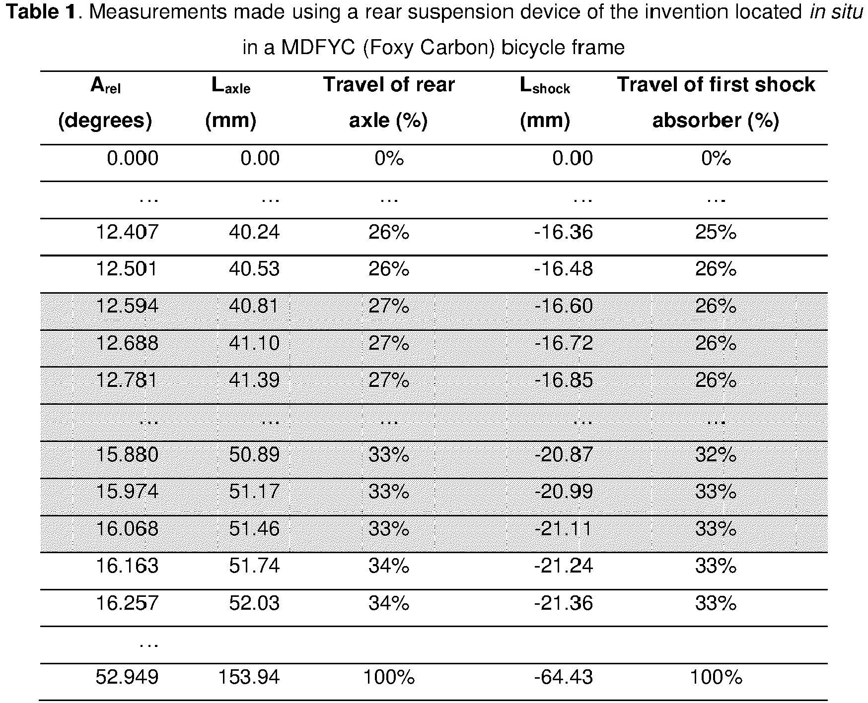
- The entries of Table 1 which are shaded grey () represent those for which the first shock absorber was considered correctly adjusted for the user (indicated by a green light on a display). The entries above those shaded grey represent those for which the compressibility of the first shock absorber should be decreased (indicated by a red light on a display), while the entries below those shaded grey represent those for which the compressibility of the first shock absorber should be increased (indicated by a yellow light on a display).

- In
Figure 3 , the front suspension device includes the same second axial compression shock absorber, magnetic flux sensor, AD22151 (803), main board (7), and cylindrical second magnet (9), as inFigure 2 . - In
Figure 3 , the rear suspension device includes an first axial compression shock absorber (7) floating in a multi-pivot Zero suspension configuration that compresses it from both ends upon upward displacement of the rear axle of the bicycle relative to the frame. The first shock absorber (7) is attached by one end to a first pivot (1, hidden) and by the other end to a second pivot (2), each of them having an axis of rotation which is parallel to the other. A linkage unit (6) is also attached to said second pivot (2), as well as to a third pivot (3) which, in turn is attached to the frame of said bicycle, and a fourth pivot (4) which in turn is attached to the seat stay of the rear triangle of the bicycle. Said linkage unit (6) rotates about the second, third, and fourth axes of rotation upon application of a load (force) to the rear wheel of the bicycle that causes the rear axle of the bicycle to be displaced upward or downward relative to the frame. The first sensor unit, AS5600 (5), which is attached to the surface of the linkage unit (6) detects the rotational movement of said first sensor unit (5) relative to the diametrically magnetized cylindrical first magnet (10) that is inserted into the hexagonal cavity of the third pivot (3) so that the surface of said magnet that is closest to said sensor unit is flush with the end surface of said third pivot (3), wherein the distance d2 between said first sensor unit and said first magnet is less than 3 mm, and the distance d1 of the Hall-effect sensors of the first sensor unit (5) from said third axis of rotation is less than or equal to the radius of the parallel faces of said first magnet. Said rotational movement of said first sensor unit (5) relative to said first magnet (10) generates a change in voltage that is detected in said sensor. - The total travel distance, Taxle of the bicycle is 150.01 mm, over which the first shock absorber travels 65 mm. Measurement of the rotational angle (relative angular displacement, Arel) through which the first sensor unit (5) moves relative to said first magnet (10) (i.e. through which the linkage unit moves relative to the bicycle frame) was performed over this range, as shown in Table 2.
- The entries of Table 2 which are shaded grey () represent those for which the first shock absorber was considered correctly adjusted for the user (indicated by a green light on a display). The entries above those shaded grey represent those for which the compressibility of the first shock absorber should be decreased (indicated by a red light on a display), while the entries below those shaded grey represent those for which the compressibility of the first shock absorber should be increased (indicated by a yellow light on a display).

- In both Examples 1 and 2, the precision in measurement of the travel of the rear axle is less than 0.3 mm, whereas if this were to be estimated based on travel of the first shock absorber, the precision would be greatly reduced.

Claims (15)
- Rear suspension device for a bicycle, wherein said device comprises:(a) a first pivot (1) having a first axis of rotation, a second pivot (2) having a second axis of rotation, and a third pivot (3) having a third axis of rotation;(b) a first axial compression shock absorber (7);(c) a linkage unit (6);(d) a first sensor unit (5); and(e) a first magnet (10)
wherein- said first axis of rotation, said second axis of rotation and said third axis of rotation are parallel;- said first axial compression shock absorber comprises a first end and a second end, wherein said first end is attached to said first pivot and said second end is attached to said second pivot; and- said linkage unit is attached to said second pivot and said third pivot and rotates about said second axis of rotation and said third axis of rotation;
characterized in that- said first sensor unit is located on a surface of said linkage unit and comprises at least one Hall-effect sensor located in a plane perpendicular to the third axis of rotation, wherein each Hall-effect sensor is located at a distance d1 from said third axis of rotation;- said first magnet is:wherein the direction of the magnetic moment of said first magnet is perpendicular to said axis of rotational symmetry, wherein said first magnet is attached to said third pivot;• a cylindrical or cylindrical shell magnet having an axis of rotational symmetry which is perpendicular to the parallel faces thereof; or• a prism-shaped magnet comprising two polygonal parallel faces and an axis of rotational symmetry which is perpendicular to said parallel faces;
wherein the third axis of rotation and the axis of rotational symmetry of said first magnet are aligned and wherein there is a distance d2 between said first sensor unit and said first magnet, and wherein:- d1 is between 0.1 mm and 50 mm; and- d2 is between 0.01 mm and 50 mm. - The rear suspension device according to claim 1, wherein said linkage unit additionally comprises a fourth pivot (4) having a fourth axis of rotation parallel to said first axis of rotation, said second axis of rotation and said third axis of rotation, and said linkage unit is additionally attached to and rotates about said fourth pivot.
- The rear suspension device according to claim 2, wherein:- said first and third pivots are for directly or indirectly attaching to the frame of said bicycle; and- said fourth pivot is for directly or indirectly attaching to the rear wheel of said bicycle.
- The rear suspension device according to any of claims 1 to 3, wherein the distance d1 is less than or equal to the longest dimension of the parallel faces of said first magnet and the distance d2 between said sensor unit and said magnet is less than 5 mm.
- The rear suspension device according to any of claims 1 to 4, wherein said first end of first axial compression shock absorber is attached to said first pivot and rotates about said first axis of rotation, and said second end of first axial compression shock absorber is attached to said second pivot and rotates about said second axis of rotation.
- The rear suspension device according to any of claims 1 to 5, wherein said first magnet is embedded in said third pivot, and the face of said magnet which is closest to said first sensor unit is flush with the end surface of said third pivot.
- A bicycle suspension system comprising the rear suspension device according to any of claims 1 to 6 in combination with a front suspension device for a bicycle and an electronic circuit (80), wherein said electronic circuit monitors the displacement measured by said rear suspension device and said front suspension device.
- A bicycle suspension system according to claim 7, wherein said front suspension device comprises:(a) a second axial compression shock absorber;(b) a second sensor unit; and(c) a second magnet (9),
wherein- said second axial compression shock absorber comprises a first end and a second end;- said second magnet is:a cylindrical magnet having a rotational axis of symmetry which is perpendicular to the parallel faces thereof; ora prism-shaped magnet comprising two polygonal parallel faces and an axis of rotational symmetry which is perpendicular to said parallel faces;wherein the direction of the magnetic moment of said first magnet is parallel to said axis of rotational symmetry, wherein said second magnet is located on said first end of said second shock absorber; and- said second sensor unit comprises a magnetic flux sensor located on the second end of said second shock absorber,
wherein said magnetic flux sensor and the rotational axis of symmetry of said second magnet are aligned. - A bicycle comprising the rear suspension device according to any of claims 1 to 6 or the bicycle suspension system according to any of claims 7 or 8.
- A method for classifying the first shock absorber of a rear suspension device according to any of claims 1 to 6 in a bicycle, as correctly or incorrectly adjusted for the user, wherein said method comprises the following steps:(a) determining the offset angle, Aoff, by measuring the angular displacement of the first sensor unit with respect to the first magnet when the first axial compression shock absorber comprised in the rear suspension device, is fully compressed;(b) determining the maximum angular displacement, Amax, by measuring the angular displacement of the first sensor unit with respect to the first magnet when the first shock absorber is fully extended;(c) determining the relative maximum angular displacement, Amaxrel, by subtracting the offset angle, Aoff, determined in step (a) from the maximum angular displacement, Amax, measured in step (b);(d) converting the relative maximum angular displacement, Amaxrel, into a total travel distance, T; and(e) measuring the angular displacement, A, of the first sensor unit with respect to the first magnet when the user is mounted on said bicycle;(f) determining the relative angular displacement, Arel, by subtracting the offset angle, Aoff, determined in step (a) from the angular displacement, A, measured in step (e);(g) converting the relative angular displacement, Arel, into a linear displacement value, L;(h) classifying said first shock absorber as:- incorrectly adjusted for said user when L is less than a value L1 or greater than a value L2; or- correctly adjusted for said user when L is between L1 and L2,wherein:- L is the linear displacement, Laxle, of the rear axle of the bicycle;- T is the total travel distance, Taxle, of the rear axle of the bicycle;- L1 is a value selected from between 10% and 50% of Taxle; and- L2 is a value selected from between 20% and 50% of Taxle,
or
wherein- L is the linear displacement, Lshock, of the first shock absorber;- T is the total travel distance, Tshock, of the first shock absorber;- L1 is a value selected from between 10% and 50% of Tshock; and- L2 is a value selected from between 20% and 50% of Tshock,
and wherein L1 is at least 0.1% less than L2. - The method according to claim 10, wherein the angular displacement is measured as a function of the voltage measured in the first sensor unit.
- The method according to any of claims 10 or 11, wherein the angular displacement, A, of the first sensor unit with respect to the first magnet is measured when only one brake is applied.
- The method according to any of claims 10 to 12, wherein steps (c), (d), (f) and (g) are carried out using the electronic circuit, optionally in conjunction with a network connected wirelessly thereto.
- The method according to any of claims 10 to 13, wherein the method is additionally for classifying the second axial compression shock absorber of a front suspension device as correctly or incorrectly adjusted for the user, wherein said method comprises the following steps:(a') determining the offset distance, Doff, by measuring the displacement of the second sensor unit with respect to the second magnet when the second axial compression shock absorber comprised in the front suspension device, is fully compressed;(b') determining the maximum displacement, Dmax, by measuring the displacement of the second sensor unit with respect to the second magnet when the second shock absorber is fully extended;(c') determining the relative maximum displacement, Dmaxrel, by subtracting the offset distance, Doff, determined in step (a') from the maximum displacement, Dmax, measured in step (b');(d') measuring the displacement, D, of the second sensor unit with respect to the second magnet when the user is mounted on said bicycle;(e') determining the relative displacement, Drel, by subtracting the offset distance, Doff, determined in step (a') from the displacement, D, measured in step (d');(f') classifying said second shock absorber as:- incorrectly adjusted for said user when Drel is less than a value L1' or greater than a value L2'; or- correctly adjusted for said user when Drel is between L1' and L2',wherein:- L1' is a value selected from between 10% and 50% of Dmaxrel; and- L2' is a value selected from between 20% and 50% of Dmaxrel,and wherein L1' is at least 0.1% less than L2'.
- The method according to any of claims 10 to 14, wherein when said first shock absorber and/or said second shock absorber is incorrectly adjusted for the user, said method informs the user how to adjust said first shock absorber and/or said second shock absorber, respectively, wherein when:- L is less than L1, the user is informed to decrease the compressibility of the first shock absorber;- L is greater than L2, the user is informed to increase the compressibility of the first shock absorber;- Drel is less than L1', the user is informed to decrease the compressibility of the second shock absorber; and/or- Drel is greater than L2', the user is informed to increase the compressibility of the second shock absorber.
Priority Applications (8)
| Application Number | Priority Date | Filing Date | Title |
|---|---|---|---|
| EP20020336.2A EP3943374B1 (en) | 2020-07-24 | 2020-07-24 | Rear suspension device, system and method for a bicycle |
| ES20020336T ES2945483T3 (en) | 2020-07-24 | 2020-07-24 | Rear suspension device, system and method for a bicycle |
| PT200203362T PT3943374T (en) | 2020-07-24 | 2020-07-24 | Rear suspension device, system and method for a bicycle |
| US18/017,611 US12304584B2 (en) | 2020-07-24 | 2021-07-23 | Rear suspension device, system and method for a bicycle |
| AU2021312334A AU2021312334A1 (en) | 2020-07-24 | 2021-07-23 | Rear suspension device, system and method for a bicycle |
| PCT/EP2021/070630 WO2022018241A1 (en) | 2020-07-24 | 2021-07-23 | Rear suspension device, system and method for a bicycle |
| CA3181334A CA3181334A1 (en) | 2020-07-24 | 2021-07-23 | Rear suspension device, system and method for a bicycle |
| CN202180039218.6A CN115697829B (en) | 2020-07-24 | 2021-07-23 | Rear suspension device, system and method for bicycle |
Applications Claiming Priority (1)
| Application Number | Priority Date | Filing Date | Title |
|---|---|---|---|
| EP20020336.2A EP3943374B1 (en) | 2020-07-24 | 2020-07-24 | Rear suspension device, system and method for a bicycle |
Publications (2)
| Publication Number | Publication Date |
|---|---|
| EP3943374A1 true EP3943374A1 (en) | 2022-01-26 |
| EP3943374B1 EP3943374B1 (en) | 2022-09-21 |
Family
ID=71786712
Family Applications (1)
| Application Number | Title | Priority Date | Filing Date |
|---|---|---|---|
| EP20020336.2A Active EP3943374B1 (en) | 2020-07-24 | 2020-07-24 | Rear suspension device, system and method for a bicycle |
Country Status (8)
| Country | Link |
|---|---|
| US (1) | US12304584B2 (en) |
| EP (1) | EP3943374B1 (en) |
| CN (1) | CN115697829B (en) |
| AU (1) | AU2021312334A1 (en) |
| CA (1) | CA3181334A1 (en) |
| ES (1) | ES2945483T3 (en) |
| PT (1) | PT3943374T (en) |
| WO (1) | WO2022018241A1 (en) |
Cited By (1)
| Publication number | Priority date | Publication date | Assignee | Title |
|---|---|---|---|---|
| WO2025012504A1 (en) * | 2023-07-12 | 2025-01-16 | Sanchez Soler, Francisco | Compact rear suspension for bicycles |
Citations (8)
| Publication number | Priority date | Publication date | Assignee | Title |
|---|---|---|---|---|
| DE202013008313U1 (en) * | 2013-07-23 | 2013-10-02 | Milan Křen | Sensor for detecting the change of the gear of the bicycle with the electrically assisted drive |
| US20150073657A1 (en) * | 2009-03-19 | 2015-03-12 | Fox Factory, Inc. | Methods and apparatus for suspension set up |
| EP3095682A1 (en) * | 2015-05-18 | 2016-11-23 | DT Swiss AG | Chassis control for a muscle- operated bicycle |
| US10094683B1 (en) * | 2017-05-15 | 2018-10-09 | Motion Instruments, Inc. | Magnetically actuated pressure sensitive suspension position sensor |
| US20190039680A1 (en) * | 2017-08-04 | 2019-02-07 | Joshua J. Angell | Active air spring |
| US20190346004A1 (en) * | 2018-05-14 | 2019-11-14 | Scott Sports Sa | Shock absorber |
| US20200079461A1 (en) * | 2018-09-07 | 2020-03-12 | Motion Instruments, Inc. | Sensor assembly for pivoting suspension of bicycle |
| US20200108884A1 (en) * | 2018-10-03 | 2020-04-09 | Motion Instruments Inc. | System for Balancing Dampening Forces on a Suspension System |
Family Cites Families (4)
| Publication number | Priority date | Publication date | Assignee | Title |
|---|---|---|---|---|
| US10036443B2 (en) * | 2009-03-19 | 2018-07-31 | Fox Factory, Inc. | Methods and apparatus for suspension adjustment |
| WO2014145085A2 (en) * | 2013-03-15 | 2014-09-18 | Jeffrey Michael | Vehicle and vehicle components |
| EP3160833A4 (en) * | 2014-06-25 | 2018-03-21 | Vasttech IP Pty Ltd | A bicycle rear wheel suspension system |
| KR102023502B1 (en) * | 2018-03-12 | 2019-09-20 | 한국컴포짓 주식회사 | Apparatus for controlling damping factor for mono plate |
-
2020
- 2020-07-24 PT PT200203362T patent/PT3943374T/en unknown
- 2020-07-24 EP EP20020336.2A patent/EP3943374B1/en active Active
- 2020-07-24 ES ES20020336T patent/ES2945483T3/en active Active
-
2021
- 2021-07-23 CN CN202180039218.6A patent/CN115697829B/en active Active
- 2021-07-23 CA CA3181334A patent/CA3181334A1/en active Pending
- 2021-07-23 WO PCT/EP2021/070630 patent/WO2022018241A1/en not_active Ceased
- 2021-07-23 AU AU2021312334A patent/AU2021312334A1/en active Pending
- 2021-07-23 US US18/017,611 patent/US12304584B2/en active Active
Patent Citations (8)
| Publication number | Priority date | Publication date | Assignee | Title |
|---|---|---|---|---|
| US20150073657A1 (en) * | 2009-03-19 | 2015-03-12 | Fox Factory, Inc. | Methods and apparatus for suspension set up |
| DE202013008313U1 (en) * | 2013-07-23 | 2013-10-02 | Milan Křen | Sensor for detecting the change of the gear of the bicycle with the electrically assisted drive |
| EP3095682A1 (en) * | 2015-05-18 | 2016-11-23 | DT Swiss AG | Chassis control for a muscle- operated bicycle |
| US10094683B1 (en) * | 2017-05-15 | 2018-10-09 | Motion Instruments, Inc. | Magnetically actuated pressure sensitive suspension position sensor |
| US20190039680A1 (en) * | 2017-08-04 | 2019-02-07 | Joshua J. Angell | Active air spring |
| US20190346004A1 (en) * | 2018-05-14 | 2019-11-14 | Scott Sports Sa | Shock absorber |
| US20200079461A1 (en) * | 2018-09-07 | 2020-03-12 | Motion Instruments, Inc. | Sensor assembly for pivoting suspension of bicycle |
| US20200108884A1 (en) * | 2018-10-03 | 2020-04-09 | Motion Instruments Inc. | System for Balancing Dampening Forces on a Suspension System |
Non-Patent Citations (1)
| Title |
|---|
| TYLER BENEDICT: "SUSPENSION SETUP SERIES #1 - SET YOUR SAG PROPERLY", 24 July 2014 (2014-07-24), XP002801539, Retrieved from the Internet <URL:https://web.archive.org/web/20140729163127/https://bikerumor.com/2014/07/24/suspension-setup-series-1-set-your-sag-properly/> [retrieved on 20201221] * |
Cited By (2)
| Publication number | Priority date | Publication date | Assignee | Title |
|---|---|---|---|---|
| WO2025012504A1 (en) * | 2023-07-12 | 2025-01-16 | Sanchez Soler, Francisco | Compact rear suspension for bicycles |
| ES2994107A1 (en) * | 2023-07-12 | 2025-01-17 | Sanchez Soler Francisco | Compact rear suspension for bicycles |
Also Published As
| Publication number | Publication date |
|---|---|
| PT3943374T (en) | 2022-12-26 |
| US20230271663A1 (en) | 2023-08-31 |
| CN115697829A (en) | 2023-02-03 |
| CA3181334A1 (en) | 2022-01-27 |
| CN115697829B (en) | 2025-09-26 |
| EP3943374B1 (en) | 2022-09-21 |
| ES2945483T3 (en) | 2023-07-03 |
| WO2022018241A1 (en) | 2022-01-27 |
| US12304584B2 (en) | 2025-05-20 |
| AU2021312334A1 (en) | 2022-11-24 |
Similar Documents
| Publication | Publication Date | Title |
|---|---|---|
| US11220173B2 (en) | Powered wheel assemblies and control systems | |
| US20210221467A1 (en) | Bicycle electric component | |
| US6050583A (en) | Electronically controlled bicycle suspension apparatus | |
| US12304584B2 (en) | Rear suspension device, system and method for a bicycle | |
| TWI792114B (en) | Bicycle suspension components and electronic monitoring devices | |
| US20150197308A1 (en) | Electronically Controlled Suspension System, Method for Controlling a Suspension System and Computer Program | |
| DK2822820T3 (en) | CONNECTING AN INTELLIGENT ELECTRIC WHEEL TO ELECTRIC CYCLES | |
| US20110113640A1 (en) | Chassis Gauge | |
| US7914024B2 (en) | Wheel suspension for a vehicle | |
| WO1984000526A1 (en) | A motorcycle front fork assembly | |
| CN204110242U (en) | Two-wheel electric motorcycle and two-wheel used for self-balancing electric vehicle | |
| US11001327B1 (en) | Pedal detection devices for bicycles | |
| CN106926949A (en) | A kind of new two-wheel electric balance car | |
| WO2017101737A1 (en) | Novel portable electric vehicle and method for controlling drive thereof | |
| CN105857475B (en) | A kind of Two-wheeled Intelligent self-balancing battery-operated motor cycle and its progress control method | |
| US20080122596A1 (en) | Device for measuring speed, particularly for cycles | |
| TWI598264B (en) | Brake rod with detachable ball end | |
| CN108657343A (en) | Self-balancing electronic drift shoes | |
| EP2504665A1 (en) | Measurement method and magnetic sensor for the contactless detection of movements | |
| US11390353B2 (en) | Operating device for human-powered vehicle | |
| JP2023534538A (en) | Cycle drive with torque sensor | |
| CN101134483A (en) | Sensor device | |
| US11912363B2 (en) | Control device for telescopic apparatus | |
| TW201925015A (en) | Braking device can easily change a standby position of a friction member | |
| US20200189679A1 (en) | A bicycle brake light system |
Legal Events
| Date | Code | Title | Description |
|---|---|---|---|
| PUAI | Public reference made under article 153(3) epc to a published international application that has entered the european phase |
Free format text: ORIGINAL CODE: 0009012 |
|
| STAA | Information on the status of an ep patent application or granted ep patent |
Free format text: STATUS: REQUEST FOR EXAMINATION WAS MADE |
|
| 17P | Request for examination filed |
Effective date: 20210702 |
|
| AK | Designated contracting states |
Kind code of ref document: A1 Designated state(s): AL AT BE BG CH CY CZ DE DK EE ES FI FR GB GR HR HU IE IS IT LI LT LU LV MC MK MT NL NO PL PT RO RS SE SI SK SM TR |
|
| GRAP | Despatch of communication of intention to grant a patent |
Free format text: ORIGINAL CODE: EPIDOSNIGR1 |
|
| STAA | Information on the status of an ep patent application or granted ep patent |
Free format text: STATUS: GRANT OF PATENT IS INTENDED |
|
| RIC1 | Information provided on ipc code assigned before grant |
Ipc: B62K 3/02 20060101ALN20220125BHEP Ipc: G01D 5/14 20060101ALI20220125BHEP Ipc: B62K 25/08 20060101ALI20220125BHEP Ipc: B62J 50/21 20200101ALI20220125BHEP Ipc: B62J 45/42 20200101ALI20220125BHEP Ipc: B62J 45/413 20200101ALI20220125BHEP Ipc: B62K 25/28 20060101AFI20220125BHEP |
|
| RIC1 | Information provided on ipc code assigned before grant |
Ipc: B62K 3/02 20060101ALN20220209BHEP Ipc: G01D 5/14 20060101ALI20220209BHEP Ipc: B62K 25/08 20060101ALI20220209BHEP Ipc: B62J 50/21 20200101ALI20220209BHEP Ipc: B62J 45/42 20200101ALI20220209BHEP Ipc: B62J 45/413 20200101ALI20220209BHEP Ipc: B62K 25/28 20060101AFI20220209BHEP |
|
| INTG | Intention to grant announced |
Effective date: 20220222 |
|
| GRAS | Grant fee paid |
Free format text: ORIGINAL CODE: EPIDOSNIGR3 |
|
| GRAA | (expected) grant |
Free format text: ORIGINAL CODE: 0009210 |
|
| STAA | Information on the status of an ep patent application or granted ep patent |
Free format text: STATUS: THE PATENT HAS BEEN GRANTED |
|
| AK | Designated contracting states |
Kind code of ref document: B1 Designated state(s): AL AT BE BG CH CY CZ DE DK EE ES FI FR GB GR HR HU IE IS IT LI LT LU LV MC MK MT NL NO PL PT RO RS SE SI SK SM TR |
|
| REG | Reference to a national code |
Ref country code: GB Ref legal event code: FG4D |
|
| REG | Reference to a national code |
Ref country code: CH Ref legal event code: EP |
|
| REG | Reference to a national code |
Ref country code: IE Ref legal event code: FG4D |
|
| REG | Reference to a national code |
Ref country code: AT Ref legal event code: REF Ref document number: 1519837 Country of ref document: AT Kind code of ref document: T Effective date: 20221015 |
|
| REG | Reference to a national code |
Ref country code: DE Ref legal event code: R096 Ref document number: 602020005169 Country of ref document: DE |
|
| REG | Reference to a national code |
Ref country code: PT Ref legal event code: SC4A Ref document number: 3943374 Country of ref document: PT Date of ref document: 20221226 Kind code of ref document: T Free format text: AVAILABILITY OF NATIONAL TRANSLATION Effective date: 20221220 |
|
| REG | Reference to a national code |
Ref country code: DK Ref legal event code: T3 Effective date: 20221220 |
|
| REG | Reference to a national code |
Ref country code: NL Ref legal event code: FP |
|
| REG | Reference to a national code |
Ref country code: LT Ref legal event code: MG9D |
|
| PG25 | Lapsed in a contracting state [announced via postgrant information from national office to epo] |
Ref country code: SE Free format text: LAPSE BECAUSE OF FAILURE TO SUBMIT A TRANSLATION OF THE DESCRIPTION OR TO PAY THE FEE WITHIN THE PRESCRIBED TIME-LIMIT Effective date: 20220921 Ref country code: RS Free format text: LAPSE BECAUSE OF FAILURE TO SUBMIT A TRANSLATION OF THE DESCRIPTION OR TO PAY THE FEE WITHIN THE PRESCRIBED TIME-LIMIT Effective date: 20220921 Ref country code: NO Free format text: LAPSE BECAUSE OF FAILURE TO SUBMIT A TRANSLATION OF THE DESCRIPTION OR TO PAY THE FEE WITHIN THE PRESCRIBED TIME-LIMIT Effective date: 20221221 Ref country code: LV Free format text: LAPSE BECAUSE OF FAILURE TO SUBMIT A TRANSLATION OF THE DESCRIPTION OR TO PAY THE FEE WITHIN THE PRESCRIBED TIME-LIMIT Effective date: 20220921 Ref country code: LT Free format text: LAPSE BECAUSE OF FAILURE TO SUBMIT A TRANSLATION OF THE DESCRIPTION OR TO PAY THE FEE WITHIN THE PRESCRIBED TIME-LIMIT Effective date: 20220921 Ref country code: FI Free format text: LAPSE BECAUSE OF FAILURE TO SUBMIT A TRANSLATION OF THE DESCRIPTION OR TO PAY THE FEE WITHIN THE PRESCRIBED TIME-LIMIT Effective date: 20220921 |
|
| PG25 | Lapsed in a contracting state [announced via postgrant information from national office to epo] |
Ref country code: HR Free format text: LAPSE BECAUSE OF FAILURE TO SUBMIT A TRANSLATION OF THE DESCRIPTION OR TO PAY THE FEE WITHIN THE PRESCRIBED TIME-LIMIT Effective date: 20220921 Ref country code: GR Free format text: LAPSE BECAUSE OF FAILURE TO SUBMIT A TRANSLATION OF THE DESCRIPTION OR TO PAY THE FEE WITHIN THE PRESCRIBED TIME-LIMIT Effective date: 20221222 |
|
| PG25 | Lapsed in a contracting state [announced via postgrant information from national office to epo] |
Ref country code: SM Free format text: LAPSE BECAUSE OF FAILURE TO SUBMIT A TRANSLATION OF THE DESCRIPTION OR TO PAY THE FEE WITHIN THE PRESCRIBED TIME-LIMIT Effective date: 20220921 Ref country code: RO Free format text: LAPSE BECAUSE OF FAILURE TO SUBMIT A TRANSLATION OF THE DESCRIPTION OR TO PAY THE FEE WITHIN THE PRESCRIBED TIME-LIMIT Effective date: 20220921 |
|
| PG25 | Lapsed in a contracting state [announced via postgrant information from national office to epo] |
Ref country code: SK Free format text: LAPSE BECAUSE OF FAILURE TO SUBMIT A TRANSLATION OF THE DESCRIPTION OR TO PAY THE FEE WITHIN THE PRESCRIBED TIME-LIMIT Effective date: 20220921 Ref country code: PL Free format text: LAPSE BECAUSE OF FAILURE TO SUBMIT A TRANSLATION OF THE DESCRIPTION OR TO PAY THE FEE WITHIN THE PRESCRIBED TIME-LIMIT Effective date: 20220921 Ref country code: IS Free format text: LAPSE BECAUSE OF FAILURE TO SUBMIT A TRANSLATION OF THE DESCRIPTION OR TO PAY THE FEE WITHIN THE PRESCRIBED TIME-LIMIT Effective date: 20230121 Ref country code: EE Free format text: LAPSE BECAUSE OF FAILURE TO SUBMIT A TRANSLATION OF THE DESCRIPTION OR TO PAY THE FEE WITHIN THE PRESCRIBED TIME-LIMIT Effective date: 20220921 |
|
| REG | Reference to a national code |
Ref country code: DE Ref legal event code: R097 Ref document number: 602020005169 Country of ref document: DE |
|
| PG25 | Lapsed in a contracting state [announced via postgrant information from national office to epo] |
Ref country code: AL Free format text: LAPSE BECAUSE OF FAILURE TO SUBMIT A TRANSLATION OF THE DESCRIPTION OR TO PAY THE FEE WITHIN THE PRESCRIBED TIME-LIMIT Effective date: 20220921 |
|
| REG | Reference to a national code |
Ref country code: ES Ref legal event code: FG2A Ref document number: 2945483 Country of ref document: ES Kind code of ref document: T3 Effective date: 20230703 |
|
| P01 | Opt-out of the competence of the unified patent court (upc) registered |
Effective date: 20230530 |
|
| PLBE | No opposition filed within time limit |
Free format text: ORIGINAL CODE: 0009261 |
|
| STAA | Information on the status of an ep patent application or granted ep patent |
Free format text: STATUS: NO OPPOSITION FILED WITHIN TIME LIMIT |
|
| 26N | No opposition filed |
Effective date: 20230622 |
|
| REG | Reference to a national code |
Ref country code: AT Ref legal event code: UEP Ref document number: 1519837 Country of ref document: AT Kind code of ref document: T Effective date: 20220921 |
|
| PG25 | Lapsed in a contracting state [announced via postgrant information from national office to epo] |
Ref country code: MC Free format text: LAPSE BECAUSE OF FAILURE TO SUBMIT A TRANSLATION OF THE DESCRIPTION OR TO PAY THE FEE WITHIN THE PRESCRIBED TIME-LIMIT Effective date: 20220921 |
|
| PG25 | Lapsed in a contracting state [announced via postgrant information from national office to epo] |
Ref country code: MC Free format text: LAPSE BECAUSE OF FAILURE TO SUBMIT A TRANSLATION OF THE DESCRIPTION OR TO PAY THE FEE WITHIN THE PRESCRIBED TIME-LIMIT Effective date: 20220921 |
|
| PG25 | Lapsed in a contracting state [announced via postgrant information from national office to epo] |
Ref country code: LU Free format text: LAPSE BECAUSE OF NON-PAYMENT OF DUE FEES Effective date: 20230724 |
|
| PG25 | Lapsed in a contracting state [announced via postgrant information from national office to epo] |
Ref country code: LU Free format text: LAPSE BECAUSE OF NON-PAYMENT OF DUE FEES Effective date: 20230724 |
|
| REG | Reference to a national code |
Ref country code: IE Ref legal event code: MM4A |
|
| PG25 | Lapsed in a contracting state [announced via postgrant information from national office to epo] |
Ref country code: IE Free format text: LAPSE BECAUSE OF NON-PAYMENT OF DUE FEES Effective date: 20230724 |
|
| PG25 | Lapsed in a contracting state [announced via postgrant information from national office to epo] |
Ref country code: IE Free format text: LAPSE BECAUSE OF NON-PAYMENT OF DUE FEES Effective date: 20230724 |
|
| PG25 | Lapsed in a contracting state [announced via postgrant information from national office to epo] |
Ref country code: BG Free format text: LAPSE BECAUSE OF FAILURE TO SUBMIT A TRANSLATION OF THE DESCRIPTION OR TO PAY THE FEE WITHIN THE PRESCRIBED TIME-LIMIT Effective date: 20220921 |
|
| PG25 | Lapsed in a contracting state [announced via postgrant information from national office to epo] |
Ref country code: BG Free format text: LAPSE BECAUSE OF FAILURE TO SUBMIT A TRANSLATION OF THE DESCRIPTION OR TO PAY THE FEE WITHIN THE PRESCRIBED TIME-LIMIT Effective date: 20220921 |
|
| PG25 | Lapsed in a contracting state [announced via postgrant information from national office to epo] |
Ref country code: CY Free format text: LAPSE BECAUSE OF FAILURE TO SUBMIT A TRANSLATION OF THE DESCRIPTION OR TO PAY THE FEE WITHIN THE PRESCRIBED TIME-LIMIT; INVALID AB INITIO Effective date: 20200724 |
|
| PG25 | Lapsed in a contracting state [announced via postgrant information from national office to epo] |
Ref country code: HU Free format text: LAPSE BECAUSE OF FAILURE TO SUBMIT A TRANSLATION OF THE DESCRIPTION OR TO PAY THE FEE WITHIN THE PRESCRIBED TIME-LIMIT; INVALID AB INITIO Effective date: 20200724 |
|
| PGFP | Annual fee paid to national office [announced via postgrant information from national office to epo] |
Ref country code: NL Payment date: 20250715 Year of fee payment: 6 |
|
| PGFP | Annual fee paid to national office [announced via postgrant information from national office to epo] |
Ref country code: ES Payment date: 20250805 Year of fee payment: 6 Ref country code: PT Payment date: 20250708 Year of fee payment: 6 |
|
| PGFP | Annual fee paid to national office [announced via postgrant information from national office to epo] |
Ref country code: DE Payment date: 20250714 Year of fee payment: 6 Ref country code: DK Payment date: 20250708 Year of fee payment: 6 |
|
| PGFP | Annual fee paid to national office [announced via postgrant information from national office to epo] |
Ref country code: IT Payment date: 20250808 Year of fee payment: 6 |
|
| PGFP | Annual fee paid to national office [announced via postgrant information from national office to epo] |
Ref country code: GB Payment date: 20250714 Year of fee payment: 6 Ref country code: BE Payment date: 20250714 Year of fee payment: 6 |
|
| PGFP | Annual fee paid to national office [announced via postgrant information from national office to epo] |
Ref country code: FR Payment date: 20250714 Year of fee payment: 6 Ref country code: AT Payment date: 20250715 Year of fee payment: 6 |
|
| PGFP | Annual fee paid to national office [announced via postgrant information from national office to epo] |
Ref country code: CH Payment date: 20250801 Year of fee payment: 6 |
|
| PGFP | Annual fee paid to national office [announced via postgrant information from national office to epo] |
Ref country code: CZ Payment date: 20250709 Year of fee payment: 6 |
|
| PG25 | Lapsed in a contracting state [announced via postgrant information from national office to epo] |
Ref country code: TR Free format text: LAPSE BECAUSE OF FAILURE TO SUBMIT A TRANSLATION OF THE DESCRIPTION OR TO PAY THE FEE WITHIN THE PRESCRIBED TIME-LIMIT Effective date: 20220921 |
|
| PG25 | Lapsed in a contracting state [announced via postgrant information from national office to epo] |
Ref country code: SI Free format text: LAPSE BECAUSE OF FAILURE TO SUBMIT A TRANSLATION OF THE DESCRIPTION OR TO PAY THE FEE WITHIN THE PRESCRIBED TIME-LIMIT Effective date: 20220921 |