EP3943028A1 - Rod system including at least two rods and connector device for rods - Google Patents
Rod system including at least two rods and connector device for rods Download PDFInfo
- Publication number
- EP3943028A1 EP3943028A1 EP20187183.7A EP20187183A EP3943028A1 EP 3943028 A1 EP3943028 A1 EP 3943028A1 EP 20187183 A EP20187183 A EP 20187183A EP 3943028 A1 EP3943028 A1 EP 3943028A1
- Authority
- EP
- European Patent Office
- Prior art keywords
- rod
- orifice
- main body
- seat
- fixation member
- Prior art date
- Legal status (The legal status is an assumption and is not a legal conclusion. Google has not performed a legal analysis and makes no representation as to the accuracy of the status listed.)
- Granted
Links
Images









Classifications
-
- A—HUMAN NECESSITIES
- A61—MEDICAL OR VETERINARY SCIENCE; HYGIENE
- A61B—DIAGNOSIS; SURGERY; IDENTIFICATION
- A61B17/00—Surgical instruments, devices or methods
- A61B17/56—Surgical instruments or methods for treatment of bones or joints; Devices specially adapted therefor
- A61B17/58—Surgical instruments or methods for treatment of bones or joints; Devices specially adapted therefor for osteosynthesis, e.g. bone plates, screws or setting implements
- A61B17/68—Internal fixation devices, including fasteners and spinal fixators, even if a part thereof projects from the skin
- A61B17/70—Spinal positioners or stabilisers, e.g. stabilisers comprising fluid filler in an implant
- A61B17/7001—Screws or hooks combined with longitudinal elements which do not contact vertebrae
- A61B17/7002—Longitudinal elements, e.g. rods
- A61B17/7014—Longitudinal elements, e.g. rods with means for adjusting the distance between two screws or hooks
-
- A—HUMAN NECESSITIES
- A61—MEDICAL OR VETERINARY SCIENCE; HYGIENE
- A61B—DIAGNOSIS; SURGERY; IDENTIFICATION
- A61B17/00—Surgical instruments, devices or methods
- A61B17/56—Surgical instruments or methods for treatment of bones or joints; Devices specially adapted therefor
- A61B17/58—Surgical instruments or methods for treatment of bones or joints; Devices specially adapted therefor for osteosynthesis, e.g. bone plates, screws or setting implements
- A61B17/68—Internal fixation devices, including fasteners and spinal fixators, even if a part thereof projects from the skin
- A61B17/70—Spinal positioners or stabilisers, e.g. stabilisers comprising fluid filler in an implant
- A61B17/7049—Connectors, not bearing on the vertebrae, for linking longitudinal elements together
- A61B17/705—Connectors, not bearing on the vertebrae, for linking longitudinal elements together for linking adjacent ends of longitudinal elements
-
- A—HUMAN NECESSITIES
- A61—MEDICAL OR VETERINARY SCIENCE; HYGIENE
- A61B—DIAGNOSIS; SURGERY; IDENTIFICATION
- A61B17/00—Surgical instruments, devices or methods
- A61B17/56—Surgical instruments or methods for treatment of bones or joints; Devices specially adapted therefor
- A61B17/58—Surgical instruments or methods for treatment of bones or joints; Devices specially adapted therefor for osteosynthesis, e.g. bone plates, screws or setting implements
- A61B17/68—Internal fixation devices, including fasteners and spinal fixators, even if a part thereof projects from the skin
- A61B17/70—Spinal positioners or stabilisers, e.g. stabilisers comprising fluid filler in an implant
- A61B17/7001—Screws or hooks combined with longitudinal elements which do not contact vertebrae
- A61B17/7002—Longitudinal elements, e.g. rods
- A61B17/7019—Longitudinal elements having flexible parts, or parts connected together, such that after implantation the elements can move relative to each other
- A61B17/7025—Longitudinal elements having flexible parts, or parts connected together, such that after implantation the elements can move relative to each other with a sliding joint
-
- A—HUMAN NECESSITIES
- A61—MEDICAL OR VETERINARY SCIENCE; HYGIENE
- A61B—DIAGNOSIS; SURGERY; IDENTIFICATION
- A61B17/00—Surgical instruments, devices or methods
- A61B17/56—Surgical instruments or methods for treatment of bones or joints; Devices specially adapted therefor
- A61B17/58—Surgical instruments or methods for treatment of bones or joints; Devices specially adapted therefor for osteosynthesis, e.g. bone plates, screws or setting implements
- A61B17/68—Internal fixation devices, including fasteners and spinal fixators, even if a part thereof projects from the skin
- A61B17/70—Spinal positioners or stabilisers, e.g. stabilisers comprising fluid filler in an implant
- A61B17/7049—Connectors, not bearing on the vertebrae, for linking longitudinal elements together
-
- A—HUMAN NECESSITIES
- A61—MEDICAL OR VETERINARY SCIENCE; HYGIENE
- A61B—DIAGNOSIS; SURGERY; IDENTIFICATION
- A61B90/00—Instruments, implements or accessories specially adapted for surgery or diagnosis and not covered by any of the groups A61B1/00 - A61B50/00, e.g. for luxation treatment or for protecting wound edges
- A61B90/03—Automatic limiting or abutting means, e.g. for safety
- A61B2090/033—Abutting means, stops, e.g. abutting on tissue or skin
- A61B2090/034—Abutting means, stops, e.g. abutting on tissue or skin abutting on parts of the device itself
Definitions
- the invention relates to a rod system including at least two rods and a connector. Further, the invention relates to a connector device for connecting at least two rods.
- the rod system is applicable in particular in the treatment of spinal deformities but can also be useful in degenerative spinal surgery, in particular in dynamic stabilization or hybrid constructs.
- rods For example, for the treatment of early onset scoliosis of the pediatric spine it is known to use growing rods. These are spinal implants fixed above and below an abnormally curved portion of the spine to correct the curvature in a first step to some extent. Thereafter, the rods are prolonged in further correction surgeries to adapt them to the growth of the spine.
- Rod systems including at least two rods that are connected to each other and that are used in various applications are known in the prior art.
- US 9,339,307 B2 describes a bone fixation device adapted to be coupled to bone anchors that allows movement of rods to permit a screw-rod construct to lengthen in response to bone growth without necessitating post surgical installation adjustment of the device.
- US 10,610,262 B2 describes a spinal distraction system including a bearing connector fastened to a fixated rod and a sliding rod, wherein the sliding rod includes a spring and a stop ring.
- connection member for coupling to one or more structural rods including a coupler body with recesses to receive the rods and a cam screw which is configured to selectively vary a size of the rod receiving recesses to impart a frictional force on the rods.
- a rod system in particular for the spine, includes a first rod, a second rod, a connector for connecting the first rod and the second rod, the connector including a main body comprising a first rod seat configured to accommodate a portion of the first rod, the first rod seat having a first longitudinal axis, and a second rod seat configured to accommodate a portion of the second rod, the second rod seat having a second longitudinal axis, wherein the connector is configured to permit the first rod to be fixed to the main body and configured to permit the second rod to be selectively either fixable to the main body or slidably connectable to the main body.
- the second rod When the second rod is slidable in the second rod seat, it can move in the axial direction of the second longitudinal axis. Also, rotation of the rod in the rod seat is possible.
- the rod system may be applied in particular in spine surgery as a correction device and/or a stabilization device.
- the connector of the rod system has a low profile. This renders it particularly suitable for the application where the available space is reduced, such as in pediatric applications.
- the connector has a small width which renders it compact and in total lightweight.
- the connector also includes one, preferably two, fixation members one of which is configured to fix the first rod to the connector and the other one is configured to fix the second rod to the connector.
- the second rod can be kept sliding relative to the connector main body.
- a closure member is provided which can be used instead of the fixation member when the second rod shall slide.
- a connector device for connecting at least two rods includes a main body comprising at least a first rod seat configured to accommodate a portion of a first rod, the first rod seat having a first longitudinal axis, a second rod seat configured to accommodate a portion of a second rod, the second rod seat having a second longitudinal axis, a fixation structure configured to fix the first rod to the main body and an orifice configured to selectively receive one of a fixation member and a closure member to either fix an inserted second rod or to close the orifice while permitting the second rod to slide.
- Such a connector device has a low profile, a compact shape and provides due to the modularity a plurality of options for use.
- a connector device for connecting at least two rods includes a main body comprising at least a first rod seat configured to accommodate a portion of a first rod, the first rod seat having a first longitudinal axis, a second rod seat configured to accommodate a portion of a second rod, the second rod seat having a second longitudinal axis, an orifice located between the first rod seat and the second rod seat, and configured to receive a fixation member, the fixation member comprising a screw with a head, preferably a monolithic screw with a head, wherein the head comprises a lower side that is configured to act on at least one of the first rod and the second rod to immobilize the first rod and/or the second rod when the first rod and/or the second rod are in the respective first and second rod seat.
- the lower side of the head is tapered, for example conically-tapered.
- the connector device comprises only few parts and has a low profile. Also, it is possible to clamp or fix the two rods simultaneously with a single fixation member. Therefore, the width of the connector device can be made small.
- At least one of the first rod seat and the second rod seat is/are configured to selectively receive pairs of rods of different diameter and wherein each of the pairs of rods of different diameter is fixed in the rod seat through clamping with the lower side of the fixation member at at least three contact areas.
- Such a connector device is configured to connect a first pair of rods each having a first diameter or a second pair of rods each having a second diameter different from the first diameter.
- the fixation member is configured to be tilted in the orifice.
- Such a connector device is configured to fix two rods having a different diameter simultaneously with the same fixation member.
- a spinal stabilization rod shall be understood as including any elongate member, regardless of the cross-sectional shape.
- a spinal stabilization rod as used herein, may have a substantially circular, oval, or angular cross-section. Such cross-section may vary along the length of the rod.
- a rod system includes a connector comprising a main body 10 and at least a first rod 100 and a second rod 101 that are intended to be connected by the connector.
- the rod system further includes at least one, optionally two fixation members 40, which may be identical.
- One of the fixation members 40 is configured to fix the first rod 100 to the main body 10.
- the other one of the fixation members 40 may be used to fix the second rod 101 to the main body, if desired.
- the rod system may include a closure member 50 that is configured to close an orifice in the main body 10 when the second rod 101 should be kept slidable.
- Sliding members 60 may also be part of the rod system that facilitate sliding of the second rod 101 in the main body 10.
- the first rod 100 and the second rod 101 may be substantially identical. They may have a circular cross-section and preferably a smooth surface. However, the rods are not limited to such design. Usually, the first rod 100 and the second rod 101 are configured to be connected to bone anchors (not shown). Such bone anchors could be, for example, pedicle screws that are inserted into the pedicles of vertebrae.
- the first rod 101 is configured to be connected to the main body 10 in such a manner that the rod is fixed, or in other words immobilized, with respect to the main body 10 using the fixation member 40.
- the second rod 101 is configured to be movable, specifically slidable, with respect to the main body 10, for example within the sliding members 60.
- the second rod 101 may alternatively be immobilized using a second fixation member 40.
- the second rod 102 may be kept slidable or may be fixed depending on the application. While it is kept sliding, the closure member 50 may be used to close the orifices.
- the main body 10 is preferably a monolithic part that has a substantially flat top 11 and a substantially flat bottom 12 that are substantially parallel to each other and define a height h of the main body 10.
- the top 11 and the bottom 12 are connected via, for example outwardly bulged cylindrical, sides 13, 14 the distance of the outermost portions of which from each other define a width w of the main body 10, as shown detailed in Fig. 4 .
- the main body 10 further has a front end 10a and a rear end 10b in a top view as shown in Fig. 3 , a distance of which defines a length 1 of the main body.
- the width w and the length 1 a height direction, a width direction and a length direction, respectively, are defined.
- first rod seat 15 is configured to receive the first rod 100 and the second rod seat 16 is configured to receive the second rod 101. More specifically, the first rod seat 15 is formed as a cylindrical channel with an inner diameter that substantially matches an outer diameter of the first rod 100 so that the first rod 100 fits therein, for example with friction.
- the first rod seat 15 defines a first longitudinal axis l 1 which may be located at the center of the main body 10 in the height direction.
- the second rod seat 16 also is a cylindrical channel defining a second longitudinal axis l 2 which may also be located at the center of the main body in the height direction.
- a central portion of the second rod seat 16 has an inner diameter that substantially matches an outer diameter of the second rod 101 so that the second rod 101 fits therein.
- the second rod seat 16 Adjacent to the front end 10a and adjacent to the rear end 10b, the second rod seat 16 comprises receiving sections 17 with a slightly greater inner diameter than the central portion of the rod seat for receiving the sliding members 60, respectively.
- Circumferential inner grooves 18 are formed in the receiving sections at a distance of the front end 10a and the rear end 10b, respectively, that are configured to receive a corresponding projection of the sliding member 60. Thereby, it can be ensured that the sliding members 60, once inserted, are held in the receiving sections 17 and are prevented from falling out of the second the rod seat 16.
- the longitudinal axis l 1 of the first rod seat 15 and the longitudinal axis l 2 of the second rod seat 16 are arranged in parallel to each other and at the same height with respect to the top 11 and/or the bottom 12.
- the rod seats 15, 16 are substantially closed around an inserted rod.
- an inserted rod is circumferentially encompassed by the rod seat at least over a certain length except at positions where the fixation member 40 acts onto the rod.
- the first orifice 19 defines a central axis c 1 as shown in Fig. 5 that extends perpendicular to the first longitudinal axis l 1 of the first rod seat 15 and perpendicular to the second longitudinal axis l 2 of the second rod seat 16.
- the first central axis c 1 of the first orifice 19 is located at a distance from the rear end 10b which distance is smaller than the distance of c 1 from the front end 10a.
- the first central axis c 1 is closer to the first rod seat 15 than to the second rod seat 16 in the width direction.
- the first orifice 19 extends completely from the top 11 to the bottom 12. Adjacent to the bottom 12, the orifice 19 comprises a threaded bore 20 for receiving a shaft of the fixation member 40 and adjacent to the top 11 it comprises an enlarged space for receiving a head of the fixation member 40 in a countersink manner.
- the enlarged space has, joining the threaded bore 20, a tapered portion 21 that tapers towards the threaded bore 20 and following the tapered portion 21 a substantially cylindrical portion 22 which opens, preferably with a small bevel 23, to the top 11.
- the tapered portion 21 and the cylindrical portion 22 intersect the first rod seat 15 at the side facing towards the first rod seat 15, such that a cutout 24 is formed that provides an opening between the first orifice 19 and the first rod seat 15.
- the cutout 24 is located above the center of the main body 10 in the height direction, so that the fixation member 40 can press from a position above the middle of the rod onto the first rod 100 when it is inserted into the first rod seat 15.
- the tapered portion 21 of the orifice 19 is spaced apart from the second rod seat 16, so that an inserted fixation member does not contact a second rod 101 inserted into the second rod seat 16.
- the second orifice 19' extends completely from the top 11 to the bottom 12 of the main body 10 and defines a second central axis c 2 .
- the second central axis c 2 of the second orifice 19' extends perpendicular to the second longitudinal axis l 2 of the second rod seat 16 and also perpendicular to the first longitudinal axis l 1 of the first rod seat 15.
- the second orifice 19' is closer to the front end 10a than to the rear end 10b of the main body 10. Moreover, it is closer to the second rod seat 16 in the width direction than the first orifice.
- the central axes c 1 , c 2 of the first and the second orifice 19, 19', respectively, are offset in the width direction.
- the second orifice 19' comprises a threaded bore 20 adjacent to the bottom 12 and an upper portion that has the cylindrical portion 22 adjacent to the top 11 and an intermediate tapered portion 21 sandwiched between them.
- the second orifice 19' is so close to the second rod seat 16 that the tapered portion 21 and the cylindrical portion 22 intersect the second rod seat 16 thereby forming a cutout 24' or opening between the second orifice 19' and the second rod seat 16 as best seen in Figs. 11 and 13 .
- the tapered portion 43 of the fixation member 40 is permitted to contact the second rod 101 when it is in the second rod seat 16.
- the tapered portion 21 is above the second longitudinal axis l 2 of the second rod seat 16.
- an inserted fixation member 40 is configured to press from an upper side of the rod on the inserted second rod 101.
- the second orifice 19' is spaced apart from the first rod seat 15 so that an inserted fixation member 40 cannot act onto the first rod 100.
- the front end 10a of the main body 10 comprises a slanted portion 10c that may extend from a distance from the opening formed by the second rod seat 16 in the front end 10a to approximately a short distance behind the second central axis c 2 of the second orifice 19' in the length direction of the main body 10, as depicted in Fig. 11 .
- a slanted surface 10c material can be saved and the connector made more compact.
- the main body has a low profile, since above and beneath the first rod seat 15 and the second rod seat 16 only a minimum of necessary material is present. Also, because the fixation members are placed into the orifices which are arranged one after the other in the length direction and the action zones 24, 24' of the fixation members 40 with the first rod 100 and the second rod 101 have only the minimum necessary distance in the width direction, the main body is very slim in the width direction. Finally, by means of the slanted portion 10c at the front end 10a the main body can be constructed more lightweight.
- the fixation member 40 is in the form of a screw having a threaded shaft 41 and a head 42.
- the threaded shaft 41 is configured to cooperate with the threaded hole 20 of the first orifice 19 and the second orifice 19', respectively.
- the head 42 has a shape that generally matches the shape of upper portion of the first orifice 19 and the second orifice 19', respectively.
- the head 42 comprises a tapered portion 43 adjacent the threaded shaft 41 that is configured to fit into the tapered portion 21 of the first and second orifice 19, 19', respectively, and a cylindrical portion 44 adjacent the tapered portion 43 that is configured to fit into the cylindrical portion 22 of the first and second orifice 19, 19'.
- a beveled portion 45 may be provided that is between the cylindrical portion 44 and a free end surface 42a of the head 42.
- a tool engagement recess 46 may be formed in the free end surface 42a.
- Various shapes of tool engagement recesses may be conceivable, such as a polygon recess, a torx-shaped recess, any type of longitudinal grooves or any other engagement structure.
- a length of the fixation member 40 along its screw axis is such, that the head 42 of the fixation member can be fully immersed or countersunk into the upper portion of the first and second orifice 19, 19', respectively and that preferably the threaded shaft 41 does not protrude substantially out of the threaded bore 20. This further contributes to the low profile of the connector.
- the tapered portion 43 which is preferably a conically-tapered portion, is permitted to touch the first rod 100 when it is in the first rod seat 15 from an upper side thereof, i.e. from a side above the middle of the rod. Tightening the fixation member 40 increases the pressure onto the first rod 100 so that the first rod 100 is immobilized in the first rod seat 15.
- the fixation member 40 is inserted into the second orifice 19' it can be fully immersed or countersunk therein, so that neither the head 42 nor preferably the threaded shaft 41 protrude out of the top 11 or the bottom 12, respectively.
- the tapered portion 43 is configured to touch the second rod 101 through the cutout 24'. Tightening the fixation member 40 in the threaded bore results in an increasing pressure onto the second rod 102 until the same is immobilized or fixed in the second rod seat 16.
- the optionally provided closure member 50 is in the form of a screw having a threaded shank 51 that is configured to cooperate with the threaded bore 20 in the first and second orifice 19, 19', respectively, and a head 52.
- the head 52 has a length in the axial direction of the screw such that it axially fits or is immersed into the upper portion of the first and second orifice 19, 19' as can be seen in particular in Fig. 6 .
- the head 52 is tapered between the shaft 51 and a substantially the free end surface 52a, wherein the taper may be steeper than that of the tapered portion 43 of the fixation member 40.
- the head 52 can be prevented from extending through the cutout 24, 24' of the first and second orifice 19, 19' and therefore prevented from contacting the first and second rod.
- a small bevel 53 adjacent the free end surface may also be formed.
- a length of the closure member 50 is such that the closure member can be immersed in the second orifice 19' without portions extending substantially out of the top 11 or the bottom 12.
- a tool engagement recess 54 is cut out that may have any suitable tool engagement shape, such as a polygon, a torx-shape or any longitudinal grooves or other suitable shape.
- the sliding members 60 are preferably identical parts.
- Each sliding member 60 is formed as a sleeve with a first end 60a and a second end 60b and a longitudinal slot 61 extending from the first end to the second end.
- the sliding member 60 is compressible such that it can be inserted into the receiving section 17 of the second rod seat 16.
- an inner diameter of the sliding member 60 is only slightly greater than an outer diameter of the second rod 101 such that the second rod 101 can slide within the sliding member 60.
- An outer base diameter of the sliding member 60 corresponds to an inner diameter of the receiving section 17 when the sliding member is inserted therein.
- a circumferential protrusion 62 is provided that fits into the groove 18 of the receiving section.
- the sliding member 60 is axially fixed in the receiving section 17.
- Adjacent the first end 60a a circumferential protrusion 63 is formed that tapers towards the first end 60a.
- the circumferential protrusion 63 extends out of the second rod seat 16 at the front end 10a of the main body 10 once the sliding member is in the receiving section 17. Thereby, further insertion of the sliding member into the second rod seat 16 is also prevented.
- the sliding members 60 are assembled with the main body 10 in such a manner that they are inserted into the second rod seat 16 with their second end 60b being the leading end.
- the main body, the first and second rod, the fixation member of fixation members and the closure member are made of a bio-compatible material such as bio-compatible metal or a metal alloy, or of a bio-compatible plastic material.
- Suitable materials may be titanium or stainless steel, NiTi alloys, for example Nitinol, or plastics like polyether ether ketone (PEEK) or poly-L-lactide acid (PLLA).
- PEEK polyether ether ketone
- PLLA poly-L-lactide acid
- the sliding members may be specifically made of a plastic material that facilitates sliding, such as PEEK or polyurethane. They may be also made of the same material as the other components of the rod system and can be coated with a coating that facilitates sliding of the second rod therein.
- the rod system is connected with bone anchors, for example two bone anchors that are inserted in vertebrae, for example of different motion segments of the spine such that the rod system bridges the respective motion segments.
- the bone anchors may be, for example, monoaxial or polyaxial pedicle screws inserted into the pedicles of the vertebrae.
- the first rod 109 may be connected to a first bone anchor at the side of the front end 10a and the second rod 101 may be connected to a second bone anchor at the side of the rear end 10b of the main body 10.
- the first rod 100 may be connected to the main body 10 in such a way that only a small portion projects out of the rear end 10b of the main body 10.
- the first rod is immobilized relative to the main body 10 by inserting the fixation member 40 into the first hole 19 and tightening the fixation member. Thereby, the slanted portion 43 of the head 42 of the fixation member presses through the cutout 24 onto the first rod 100 to fix the same.
- the frictional force holding the rod can be adjusted.
- a friction hold that can be manually overcome may be sufficient, whereas for final fixation the fixation member can be fully tightened.
- the second rod 101 may be connected to the second bone anchor while it is kept sliding with respect to the main body 10. Due to the sliding members, the sliding is considerably facilitated. Hence, the second rod 101 allows the distance between the first and the second bone anchor to continuously vary corresponding to the sliding of the second rod with respect to the main body and therefore with respect to the fixed first rod 100.
- the closure member 50 may be inserted to close the orifice so that it can be maintained substantially free from vessels or tissue growing into the second orifice 19'.
- another fixation member 40 can be inserted into the second orifice 19' to clamp and fix the second rod 102 at a desired axial position with respect to the main body 10. When tightening the fixation member 40 , the tapered portion 43 presses through the cutout 24' onto the second rod 102 until the same is immobilized.
- a surgeon can selectively use either another fixation member 40 to fix the second rod 101 or a closure member 50 to close the second orifice 19'.
- the rod system can be used, for example, as a growing rod system.
- the second rod 102 can be fixed and the first rod 100 can be kept slidable or, alternatively both rods can be kept slidable.
- a stop may be for example, a clamping ring around the free end of the sliding rod which is close to the main body.
- the stabilization system provides a modular system that permits a multitude of applications with sliding and/or fixed rods.
- the rod system according to the second embodiment differs from the rod system of the first embodiment mainly in that the first rod is permanently fixed to the main body of the connector using a pin 70.
- a pin hole 27 for receiving the pin extends from the top 11 completely to the bottom 12 and is arranged offset from the middle of the main body 10' in the width direction towards the first rod seat 15.
- the pin hole 27 has such a size and is positioned at such a positon that it intersects the first rod seat 15 as shown in particular in Fig. 27 . In the length direction, the pin hole 27 is formed approximately at the center of the main body 10'. A central axis of the pin hole 27 extends perpendicular to the first longitudinal axis l 1 of the first rod seat 15.
- the first rod 100' comprises a substantially cylindrical recessed portion 100a that is at an axial position corresponding to the pin hole when the first rod 100' is inserted into the first rod seat and projects only slightly out of the rear end 10b.
- the pin 70 forms a first fixation member that is configured to be inserted into the pin hole 70 thereby engaging the recessed portion 100a of the first rod 100 when the first rod 100 is in the first rod seat 15.
- a third orifice 119 is formed in the main body 10' between the second orifice 19' and the rear end 10b.
- the third orifice 119 comprises a central axis that is perpendicular to the longitudinal axes l 1 and l 2 of the first and second rod seats 15, 16 and positioned in the width direction at the same position as the central axis c 2 of the second orifice 19'.
- the third orifice 119 is identical in shape to the second orifice 19'.
- there is a cutout 124 forming an opening between the third orifice 119 and the second rod seat 16.
- the pin hole 27 may be arranged in the middle between the second orifice 19' and the third orifice 119 on the side facing towards the first rod seat 15.
- the first rod 100 is fixed to the main body 10' in a specific axial position.
- the fixation is effected by the pin 70 engaging the recess 100a of the first rod 100.
- the pin may be press-fit into the pin hole 27 the axial and rotational fixation of the first rod 100 is permanent during ordinary use of the rod system.
- the rod 100 can also be welded to the main body 10' so that the connection is non releasable.
- two fixation members 40 can be placed into the second and third orifice 19', 119, respectively, so that an enhanced fixation can be achieved by using two fixation members.
- one fixation member 40 and one closure member 50 may be used or two closure members 50 may be used for the second and third orifices 19, 119 to keep the second rod 16 sliding.
- the orifices 119', 119 can also remain open, i.e. without inserting a closure member 50.
- the first rod 100 and the main body 10' can be a monolithic part. They may be, for example, machined out of one piece of material. In this modified embodiment, the pin is not needed.
- the first rod 100' is identical to that of the second embodiment, i.e. comprises the recess 100a for engagement with the pin 70.
- the main body 10" lacks the third orifice 119 of the second embodiment. As a result, the main body 10" only comprises the pin hole 27 for engagement with the pin 70 and one orifice 119 for receiving a fixation member 40 or a closure member 50.
- the front end 10a lacks the slanted portion 10c so that the front end 10a is substantially parallel to the rear end 10b over the whole width.
- the first rod 100' is fixed to the main body 10" via the pin 70 which is press-fit into the pin hole 27.
- the first rod 100' can be welded to the main body 10".
- the second rod 101 can be fixed via fixation member 40 or can slide in the second rod seat 16.
- the rod system according to the third embodiment has an even more reduced size in the length direction.
- the first rod 100' and the main body 10" can also be a monolithic part, so that the pin is not needed.
- the rod system comprises a rod 200 which may be identical to the rod 100 or 101 of the previous embodiments and a connector comprising a main body 1000 and a fixation member 40.
- the main body 1000 is a body with a top 11', a bottom 12' and sides 13', 14' wherein the sides may have a substantially cylindrical outer surface. It shall be noted, however, that the overall shape of the main body can be any shape, for example also a cuboid.
- a single rod seat 150 is formed which is substantially cylinder segment-shaped for a circular rod 200.
- the rod seat is open, that means the circular rod can be inserted from the top 11'.
- an orifice 190 is formed a central axis c of which extends perpendicular to the longitudinal axis 1 of the rod seat 150.
- the orifice 190 comprises a threaded hole 191 that is configured to receive the threaded shaft 41 of the fixation member 40.
- the orifice 190 may have a tapered portion 192 receiving the tapered portion 43 of the fixation member 40.
- the inserted rod is accessible by the head of the fixation member 40.
- the orifice 190 is at such a position that when the fixation member 40 is inserted into the orifice 190 and tightened, the tapered portion 43 of the head 42 of the fixation member 40 contacts the rod 200 from above and presses the rod 200 into the rod seat 150.
- the rod 200 is fixed or immobilized only by tightening the fixation member.
- the rod system comprises only a few parts of simple structure.
- the connector has a very low profile.
- the rod system differs from the rod system from Figs. 31 and 32 mainly in that the main body 1000' comprises a rod seat in the form of a sleeve-like portion 150' that may comprise a sleeve-like prolongation or extension 200 with a smaller outer diameter.
- the two portions 150' and 200 form a rod extension in which a further rod (not shown) can be inserted.
- the rod seat is substantially closed around an inserted rod.
- An outer contour of the main body 1000' in the portion around the orifice 190 may be substantially rectangular with one side attached to the sleeve-like portion forming the rod seat 150'.
- the upper portion of the orifice 190 intersects the rod seat portion 150' such that a cutout 124' forms an opening that permits the tapered portion 43 of the head 42 of the fixation member 40 to press on an upper portion of an inserted rod.
- a free end surface in the axial direction of the rod seat portion 150' may be open or closed. In use, tightening the fixation member 40 against an inserted rod clamps and finally fixes the rod in the axial position.
- a still further embodiment of a rod system comprises two rods 100, 101 of the same diameter, a main body 1000" and a fixation member 40.
- the main body 1000" has a top 11", an opposite bottom 12" which are substantially parallel, two outwardly bulged cylinder segment-shaped sides 13", 14" joining the top 11", the bottom 12" and a front end 1000"a and a rear end (not visible in the Figures).
- two cylinder segment-shaped rod seats 150", 160” are formed having longitudinal axes l 1 and l 2 , respectively, that are substantially parallel to each other.
- the rod seats 150", 160” are open so that the rods can be inserted from the top 11".
- an orifice 190" is formed that comprises a threaded hole 191".
- a length of the threaded hole 191" is such that when the fixation member 40 is inserted with the threaded shaft 41 it can be tightened to press with the tapered portion 43 onto an upper side of the rods 100, 101 which are inserted into the first and second rod seats 150", 160". With the fixation member 40, both rods can be fixed simultaneously.
- the rod system has few parts, a simple structure and a low profile.
- the rod system is configured to be used with various sets of rods wherein the sets differ with respect to the diameter of the rods.
- the main body 1000' is similar to the main body 1000" of the previous embodiment, however, the rod seats 150'", 160'" are configured to receive rods of various diameters.
- the rod seats 150"', 160'" can receive a pair of rods 100, 101 of the same first diameter and can alternatively, as depicted in Fig.
- the main body 1000' comprises a top 11'", an opposite bottom 12'" and sides 13"', 14'" which may be cylindrically-shaped and connect the top, the bottom and a front end 1000"'a and a rear end 1000"'b.
- an orifice 190'" is provided for receiving a fixation member 40'.
- the first rod seat 150"' comprises a cylindrical portion 150"'a and a substantially V-shaped portion 150"'b (seen in cross-section), preferably with a rounded bottom, that joins the cylindrical portion 150"'a in a continuous manner.
- the sidewalls of the V-shaped contour may form an angle between 45° and 135°, preferably around 90°.
- the cylindrical portion 150"'a is closer to the center of the main body or closer to the orifice in the width direction whereas the V-shaped portion 150"'b is located closer to the side 13"'.
- the second rod seat 160'" comprises a cylindrical portion 160"'a arranged closer to the center in the width direction and V-shaped portion 160"'b, preferably with a rounded bottom, that joins the cylindrical portion 160"'a in a continuous manner and that is located closer to the side 14'" than the cylindrical portion 160"'a.
- the shape of the cylindrical section and of V-groove section of both rod seats may be identical and mirror symmetrical to a plane extending through the orifice 190'" in the height direction.
- the orifice 190'" comprises a threaded portion 191'" adjacent to the bottom 12'" and a tapered portion 192'" adjacent to the top 11'".
- the orifice 190'" is configured to receive the fixation member 40' which differs from the fixation member 40 in that the head 42 has an enlarged tapered surface 43' and may have an axially reduced height of the cylindrical portion 44'.
- the rods In use, when a first pair of rods 100, 101 is used that has a first diameter corresponding to the inner diameter of the cylindrical portion 150"'a and 160"'a of the rod seats 150"', 160"', respectively, the rods each substantially fill the rod seat except a small portion in the ground region of the V-shaped portion.
- the fixation member 40' is inserted into the orifice 190'" touches with the tapered portion 43' onto the upper side of both rods while the threaded shaft 41 may not extend fully into the threaded portion 191"' as depicted in Fig. 38 .
- the rods 100', 101' do not fully fill the rod seats in the cylindrical portion 150"'a, 160"'a but rest on the flanks of the V-shaped portion 150"'b, 160"'b along substantially two contact areas that are substantially parallel to the longitudinal axes l 1 , l 2 of the rod seats. Inserting the fixation member 40' and tightening the same against the rods 100', 101' allows the fixation member 40' to extend deeper into the threaded portion 191'" so that the tapered portion 43' the head 42' of the fixation member 40' contacts the rods 100', 101' at a position farther outward in the radial direction of the head.
- the rods 100', 101' are firmly clamped along three contact areas wherein two of the contact areas are in the V-shaped portion of the rod seat and the third is at the tapered portion 43' of the fixation member 40'.
- the rod system according to this embodiment differs from the rod system according to the previous embodiment that a pair of rods with different diameter can be used and fixed simultaneously with a single fixation member.
- a first rod 100" has a smaller outer diameter compared to a second rod 101".
- the main body 1000"" comprises the first rod seat 150"' and the second rod seat 160'" as in the previous embodiment.
- the first rod 101" is configured to be received in the first rod seat 150"' and the second rod 101" is configured to be received in the second rod seat 160"'.
- the orifice 190"" between the first rod seat 150"' and the second rod seat 160'” is configured to receive a fixation member 40" and a pivot sleeve 80.
- the orifice 190"" comprises adjacent to the bottom 12'" a spherical segment-shaped recess 193 which extends over the region with a greatest diameter of the sphere, i.e. over the equator.
- the spherical segment-shaped recess 193 is configured to receive the pivot sleeve 80.
- the pivot sleeve 80 comprises a spherical segment-shaped outer surface 81 and an inner cylindrical threaded passage 82 that is configured to cooperate with the threaded shank 41" of the fixation member 40".
- the pivot sleeve 80 further comprises an axial slot 83 that renders it compressible and expandable.
- a tapered, preferably conically-tapered, portion 194 Adjacent to the spherical segment-shaped recess 193 a tapered, preferably conically-tapered, portion 194 is formed in the orifice 190"" that widens towards the top 11'".
- the tapered portion 194 may have a smaller inner diameter at the junction to the spherical segment-shaped recess 193 than an inner diameter of the spherical segment-shaped recess 193 at the junction.
- the tapered portion 194 permits the threaded shank 41" to be tilted in the orifice 190"".
- the head 42 of the fixation member 40" comprises a tapered section 43 and a cylindrical section 44.
- the pivot sleeve 80 may be inserted into the main body 1000"" by compressing it so that it can snap into the recess 193 where it is held by friction. Thereafter, the rods 100" and 101" may be placed in their respective rod seats 150"', 160'". Finally, the fixation member 40" is inserted into the orifice such that its shaft 41" engages the threaded inner side 82 of the pivot sleeve 80. In this configuration, the fixation member 40" can can be tilted to some extent around its screw axis so that it can clamp both rods simultaneously as the tapered portion 43 provides the third contact area for each of the rods that rest in the V-shaped portion of the rod seat, respectively.
- two rods 100, 101 of the same diameter are used as shown in Fig. 47 .
- the screw axis of the fixation member 40" is in the zero position, i.e. is perpendicular to both longitudinal axes of the rod seats.
- bone anchoring element For the bone anchoring element that is not shown, all types of bone anchoring elements that are suitable for anchoring in bone or a vertebra and configured to be connected to a rod may be used.
Landscapes
- Health & Medical Sciences (AREA)
- Orthopedic Medicine & Surgery (AREA)
- Life Sciences & Earth Sciences (AREA)
- Neurology (AREA)
- Surgery (AREA)
- Heart & Thoracic Surgery (AREA)
- Engineering & Computer Science (AREA)
- Biomedical Technology (AREA)
- Nuclear Medicine, Radiotherapy & Molecular Imaging (AREA)
- Medical Informatics (AREA)
- Molecular Biology (AREA)
- Animal Behavior & Ethology (AREA)
- General Health & Medical Sciences (AREA)
- Public Health (AREA)
- Veterinary Medicine (AREA)
- Surgical Instruments (AREA)
Abstract
Description
- The invention relates to a rod system including at least two rods and a connector. Further, the invention relates to a connector device for connecting at least two rods. The rod system is applicable in particular in the treatment of spinal deformities but can also be useful in degenerative spinal surgery, in particular in dynamic stabilization or hybrid constructs.
- For example, for the treatment of early onset scoliosis of the pediatric spine it is known to use growing rods. These are spinal implants fixed above and below an abnormally curved portion of the spine to correct the curvature in a first step to some extent. Thereafter, the rods are prolonged in further correction surgeries to adapt them to the growth of the spine.
- Rod systems including at least two rods that are connected to each other and that are used in various applications are known in the prior art.
- For example,
US 9,339,307 B2 - Moreover,
US 10,610,262 B2 -
US 2006/0233597 describes a connection member for coupling to one or more structural rods including a coupler body with recesses to receive the rods and a cam screw which is configured to selectively vary a size of the rod receiving recesses to impart a frictional force on the rods. - It is the object of the invention to provide a rod system including at least two rods and to provide a connector device for at least two rods that permit an improved or alternative way of treating various spine disorders, conditions and/or diseases, in particular spinal deformities and more particularly deformities in the pediatric or juvenile spine, or in degenerative spinal surgery, in particular in dynamic stabilization or hybrid construct applications.
- The object is solved by a rod system of
claim 1 or 16, and by a connector device ofclaim - According to an embodiment, a rod system, in particular for the spine, includes a first rod, a second rod, a connector for connecting the first rod and the second rod, the connector including a main body comprising a first rod seat configured to accommodate a portion of the first rod, the first rod seat having a first longitudinal axis, and a second rod seat configured to accommodate a portion of the second rod, the second rod seat having a second longitudinal axis, wherein the connector is configured to permit the first rod to be fixed to the main body and configured to permit the second rod to be selectively either fixable to the main body or slidably connectable to the main body. When the second rod is slidable in the second rod seat, it can move in the axial direction of the second longitudinal axis. Also, rotation of the rod in the rod seat is possible.
- The rod system may be applied in particular in spine surgery as a correction device and/or a stabilization device.
- The connector of the rod system has a low profile. This renders it particularly suitable for the application where the available space is reduced, such as in pediatric applications. In addition, the connector has a small width which renders it compact and in total lightweight.
- In a further development, the connector also includes one, preferably two, fixation members one of which is configured to fix the first rod to the connector and the other one is configured to fix the second rod to the connector. Alternatively, the second rod can be kept sliding relative to the connector main body. In a further development, a closure member is provided which can be used instead of the fixation member when the second rod shall slide. Thus, the rod system forms a modular system that opens up various methods of use.
- According to an embodiment, a connector device for connecting at least two rods includes a main body comprising at least a first rod seat configured to accommodate a portion of a first rod, the first rod seat having a first longitudinal axis, a second rod seat configured to accommodate a portion of a second rod, the second rod seat having a second longitudinal axis, a fixation structure configured to fix the first rod to the main body and an orifice configured to selectively receive one of a fixation member and a closure member to either fix an inserted second rod or to close the orifice while permitting the second rod to slide.
- Such a connector device has a low profile, a compact shape and provides due to the modularity a plurality of options for use.
- According to a still further embodiment, a connector device for connecting at least two rods includes a main body comprising at least a first rod seat configured to accommodate a portion of a first rod, the first rod seat having a first longitudinal axis, a second rod seat configured to accommodate a portion of a second rod, the second rod seat having a second longitudinal axis, an orifice located between the first rod seat and the second rod seat, and configured to receive a fixation member, the fixation member comprising a screw with a head, preferably a monolithic screw with a head, wherein the head comprises a lower side that is configured to act on at least one of the first rod and the second rod to immobilize the first rod and/or the second rod when the first rod and/or the second rod are in the respective first and second rod seat. Preferably the lower side of the head is tapered, for example conically-tapered.
- The connector device comprises only few parts and has a low profile. Also, it is possible to clamp or fix the two rods simultaneously with a single fixation member. Therefore, the width of the connector device can be made small.
- In a further embodiment, at least one of the first rod seat and the second rod seat, preferably both rod seats, is/are configured to selectively receive pairs of rods of different diameter and wherein each of the pairs of rods of different diameter is fixed in the rod seat through clamping with the lower side of the fixation member at at least three contact areas.
- Such a connector device is configured to connect a first pair of rods each having a first diameter or a second pair of rods each having a second diameter different from the first diameter.
- In a still further embodiment, the fixation member is configured to be tilted in the orifice. Such a connector device is configured to fix two rods having a different diameter simultaneously with the same fixation member.
- As used in the present specification and the appended claims, the term "rod" shall be understood as including any elongate member, regardless of the cross-sectional shape. Specifically, a spinal stabilization rod as used herein, may have a substantially circular, oval, or angular cross-section. Such cross-section may vary along the length of the rod.
- Further features and advantages of the invention will become apparent from the description of embodiments by means of the accompanying drawings. In the drawings:
- Fig. 1:
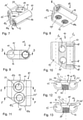
- shows a perspective exploded view of a rod system according to a first embodiment.
- Fig. 2:
- shows a perspective view of the rod system of
Fig. 1 in an assembled state. - Fig. 3:
- shows a top view of the rod system of
Figs. 1 and 2 . - Fig. 4:
- shows a cross-sectional view of the rod system along line A-A in
Fig. 3 . - Fig. 5:
- shows a cross-sectional view of the rod system along line B-B in
Fig. 3 . - Fig. 6:
- shows a cross-sectional view of the rod system along line C-C in
Fig. 3 . - Fig. 7:
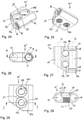
- shows a perspective view from the top of a main body of a connector of the rod system of
Figs. 1 to 6 . - Fig. 8:
- shows a perspective view from the bottom of the main body shown in
Fig. 7 . - Fig. 9:
- shows a front view of the main body of
Fig. 7 in the direction of a longitudinal axis of one rod seat. - Fig. 10
- shows a cross-sectional view of the main body along line D-D in
Fig. 9 . - Fig. 11:
- shows a top view of the main body of
Figs. 7 to 10 . - Fig. 12:
- shows a cross-sectional view of the main body along line E-E in
Fig. 11 . - Fig. 13:
- shows a cross-sectional view of the main body along line F-F in
Fig. 11 . - Fig. 14:
- shows a perspective view of a fixation member of the rod system of
Figs. 1 to 13 . - Fig. 15:
- shows a side-view of the fixation member of
Fig. 14 . - Fig. 16:
- shows a closure member of the rod system of
Figs. 1 to 13 . - Fig. 17:
- shows a side-view of the closure member of
Fig. 16 . - Fig. 18:
- shows a perspective view from the top of a sliding member of the rod system of
Figs. 1 to 13 . - Fig. 19:
- shows a perspective view from the bottom of the sliding member of
Fig. 18 . - Fig. 20:
- shows a top view of the sliding member of
Figs. 18 and 19 . - Fig. 21:
- shows a cross-sectional view of the sliding member along line G-G in
Fig. 20 . - Fig. 22:
- shows a perspective exploded view of a rod system according to a second embodiment.
- Fig. 23:
- shows a perspective view of the rod system according to the second embodiment of
Fig. 22 in an assembled state. - Fig. 24:
- shows a perspective view from the top of a main body of a connector of the rod system of
Figs. 22 and 23 . - Fig. 25:
- shows a perspective view from the bottom of the main body of
Fig. 24 . - Fig. 26:
- shows a front view of the main body of
Figs. 24 and 25 in a direction along a longitudinal axis of one rod seat. - Fig. 27:
- shows a cross-sectional view of the main body along line H-H in
Fig. 26 . - Fig. 28:
- shows a top view of the main body of
Figs. 24 to 27 . - Fig. 29:
- shows a cross-sectional view of the main body along line I-I in
Fig. 28 . - Fig. 30:
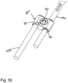
- shows a perspective view of a rod system according to a third embodiment in an assembled state.
- Fig. 31:
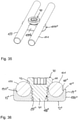
- shows a perspective view of a rod system including only one rod according to a further embodiment.
- Fig. 32:
- shows a cross-sectional view of the rod system of
Fig. 31 , the cross-section taken in a plane perpendicular to a longitudinal axis of a rod and extending through the center of a fixation member. - Fig. 33:
- shows a perspective view of another embodiment of a rod system including only one rod.
- Fig. 34:
- shows a cross-sectional view of the rod system of
Fig. 33 the cross-section taken in a plane perpendicular to the longitudinal axis of a rod and extending through the center of a fixation member. - Fig. 35:
- shows a perspective view of a still further embodiment of a rod system.
- Fig. 36:
- shows a cross-sectional view of the rod system of
Fig. 35 , the cross-section taken in a plane perpendicular to the longitudinal axes of the two inserted rods and extending through a center of a fixation member. - Fig. 37:
- shows a perspective view of a still further embodiment of a rod system in an assembled state.
- Fig. 38:
- shows a cross-sectional view of the rod system of
Fig. 37 , the cross-section taken in a plane perpendicular to the longitudinal axes of the two inserted rods and extending through a center of the fixation member, wherein the rods each have a first diameter. - Fig. 39:
- shows a cross-sectional view of the rod system with two inserted rods each having a second diameter, smaller than the first diameter of the rods shown in
Fig. 38 . - Fig. 40:
- shows a perspective view from the top of a main body of a connector of the rod system shown in
Figs. 37 to 39 . - Fig. 41:
- shows a perspective view from the bottom of the connector of
Fig. 40 . - Fig. 42:
- shows a top view of the main body of
Figs. 40 and 41 . - Fig. 43:
- shows a cross-sectional view of the main body along line J-J in
Fig. 42 . - Fig. 44:
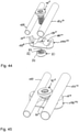
- shows a perspective exploded view of a rod system of a still further embodiment.
- Fig. 45:
- shows a perspective view of the rod system of
Fig. 44 in an assembled state. - Fig. 46:
- shows a cross-sectional view of the rod system of
Figs. 44 to 45 , the cross-section taken in a plane perpendicular to the longitudinal axes of the two inserted rods and extending through a center of a fixation member, wherein the rods have a different diameter. - Fig. 47:
- shows a cross-sectional view like shown in
Fig. 46 with two rods having the same diameter. - Referring to
Figs. 1 and 2 , a rod system according to a first embodiment includes a connector comprising amain body 10 and at least afirst rod 100 and asecond rod 101 that are intended to be connected by the connector. The rod system further includes at least one, optionally twofixation members 40, which may be identical. One of thefixation members 40 is configured to fix thefirst rod 100 to themain body 10. The other one of thefixation members 40 may be used to fix thesecond rod 101 to the main body, if desired. Further optionally, the rod system may include aclosure member 50 that is configured to close an orifice in themain body 10 when thesecond rod 101 should be kept slidable. Slidingmembers 60 may also be part of the rod system that facilitate sliding of thesecond rod 101 in themain body 10. - The
first rod 100 and thesecond rod 101 may be substantially identical. They may have a circular cross-section and preferably a smooth surface. However, the rods are not limited to such design. Usually, thefirst rod 100 and thesecond rod 101 are configured to be connected to bone anchors (not shown). Such bone anchors could be, for example, pedicle screws that are inserted into the pedicles of vertebrae. - The
first rod 101 is configured to be connected to themain body 10 in such a manner that the rod is fixed, or in other words immobilized, with respect to themain body 10 using thefixation member 40. Thesecond rod 101 is configured to be movable, specifically slidable, with respect to themain body 10, for example within the slidingmembers 60. Thesecond rod 101 may alternatively be immobilized using asecond fixation member 40. Hence, the second rod 102 may be kept slidable or may be fixed depending on the application. While it is kept sliding, theclosure member 50 may be used to close the orifices. - Referring in addition to
Figs. 3 to 13 , themain body 10 will be described more in detail. Themain body 10 is preferably a monolithic part that has a substantially flat top 11 and a substantially flat bottom 12 that are substantially parallel to each other and define a height h of themain body 10. The top 11 and the bottom 12 are connected via, for example outwardly bulged cylindrical, sides 13, 14 the distance of the outermost portions of which from each other define a width w of themain body 10, as shown detailed inFig. 4 . Themain body 10 further has afront end 10a and arear end 10b in a top view as shown inFig. 3 , a distance of which defines a length 1 of the main body. By the height h, the width w and the length 1 a height direction, a width direction and a length direction, respectively, are defined. - At a distance from each of the
sides first rod seat 15 and asecond rod seat 16, respectively, that each extend from thefront end 10a to therear end 10b completely through themain body 10. Thefirst rod seat 15 is configured to receive thefirst rod 100 and thesecond rod seat 16 is configured to receive thesecond rod 101. More specifically, thefirst rod seat 15 is formed as a cylindrical channel with an inner diameter that substantially matches an outer diameter of thefirst rod 100 so that thefirst rod 100 fits therein, for example with friction. Thefirst rod seat 15 defines a first longitudinal axis l1 which may be located at the center of themain body 10 in the height direction. Thesecond rod seat 16 also is a cylindrical channel defining a second longitudinal axis l2 which may also be located at the center of the main body in the height direction. A central portion of thesecond rod seat 16 has an inner diameter that substantially matches an outer diameter of thesecond rod 101 so that thesecond rod 101 fits therein. Adjacent to thefront end 10a and adjacent to therear end 10b, thesecond rod seat 16 comprises receivingsections 17 with a slightly greater inner diameter than the central portion of the rod seat for receiving the slidingmembers 60, respectively. Circumferentialinner grooves 18 are formed in the receiving sections at a distance of thefront end 10a and therear end 10b, respectively, that are configured to receive a corresponding projection of the slidingmember 60. Thereby, it can be ensured that the slidingmembers 60, once inserted, are held in the receivingsections 17 and are prevented from falling out of the second therod seat 16. - The longitudinal axis l1 of the
first rod seat 15 and the longitudinal axis l2 of thesecond rod seat 16 are arranged in parallel to each other and at the same height with respect to the top 11 and/or the bottom 12. As can be seen in the figures, the rod seats 15, 16 are substantially closed around an inserted rod. Thus, an inserted rod is circumferentially encompassed by the rod seat at least over a certain length except at positions where thefixation member 40 acts onto the rod. - Between the
first rod seat 15 and thesecond rod seat 16, afirst orifice 19 and a second orifice 19' are formed that serve for selectively receiving thefixation member 40 or theclosure member 50. Thefirst orifice 19 defines a central axis c1 as shown inFig. 5 that extends perpendicular to the first longitudinal axis l1 of thefirst rod seat 15 and perpendicular to the second longitudinal axis l2 of thesecond rod seat 16. The first central axis c1 of thefirst orifice 19 is located at a distance from therear end 10b which distance is smaller than the distance of c1 from thefront end 10a. Moreover, the first central axis c1 is closer to thefirst rod seat 15 than to thesecond rod seat 16 in the width direction. - The
first orifice 19 extends completely from the top 11 to the bottom 12. Adjacent to the bottom 12, theorifice 19 comprises a threadedbore 20 for receiving a shaft of thefixation member 40 and adjacent to the top 11 it comprises an enlarged space for receiving a head of thefixation member 40 in a countersink manner. The enlarged space has, joining the threaded bore 20, a taperedportion 21 that tapers towards the threaded bore 20 and following the tapered portion 21 a substantiallycylindrical portion 22 which opens, preferably with asmall bevel 23, to the top 11. The taperedportion 21 and thecylindrical portion 22 intersect thefirst rod seat 15 at the side facing towards thefirst rod seat 15, such that acutout 24 is formed that provides an opening between thefirst orifice 19 and thefirst rod seat 15. Referring toFigs. 5 and12 in particular, thecutout 24 is located above the center of themain body 10 in the height direction, so that thefixation member 40 can press from a position above the middle of the rod onto thefirst rod 100 when it is inserted into thefirst rod seat 15. On the opposite side of thecutout 24 in the width direction, the taperedportion 21 of theorifice 19 is spaced apart from thesecond rod seat 16, so that an inserted fixation member does not contact asecond rod 101 inserted into thesecond rod seat 16. - Referring now in more detail to
Figs. 3 and10 , the second orifice 19' extends completely from the top 11 to the bottom 12 of themain body 10 and defines a second central axis c2. The second central axis c2 of the second orifice 19' extends perpendicular to the second longitudinal axis l2 of thesecond rod seat 16 and also perpendicular to the first longitudinal axis l1 of thefirst rod seat 15. The second orifice 19' is closer to thefront end 10a than to therear end 10b of themain body 10. Moreover, it is closer to thesecond rod seat 16 in the width direction than the first orifice. As a result, the central axes c1, c2 of the first and thesecond orifice 19, 19', respectively, are offset in the width direction. Similar to thefirst orifice 19, the second orifice 19' comprises a threadedbore 20 adjacent to the bottom 12 and an upper portion that has thecylindrical portion 22 adjacent to the top 11 and an intermediate taperedportion 21 sandwiched between them. The second orifice 19' is so close to thesecond rod seat 16 that the taperedportion 21 and thecylindrical portion 22 intersect thesecond rod seat 16 thereby forming a cutout 24' or opening between the second orifice 19' and thesecond rod seat 16 as best seen inFigs. 11 and 13 . By means of the cutout 24', the taperedportion 43 of thefixation member 40 is permitted to contact thesecond rod 101 when it is in thesecond rod seat 16. The taperedportion 21 is above the second longitudinal axis l2 of thesecond rod seat 16. Hence, an insertedfixation member 40 is configured to press from an upper side of the rod on the insertedsecond rod 101. At the opposite side of the cutout 24' in the width direction, the second orifice 19' is spaced apart from thefirst rod seat 15 so that an insertedfixation member 40 cannot act onto thefirst rod 100. - Lastly, the
front end 10a of themain body 10 comprises a slantedportion 10c that may extend from a distance from the opening formed by thesecond rod seat 16 in thefront end 10a to approximately a short distance behind the second central axis c2 of the second orifice 19' in the length direction of themain body 10, as depicted inFig. 11 . By means of the slantedsurface 10c material can be saved and the connector made more compact. - The main body has a low profile, since above and beneath the
first rod seat 15 and thesecond rod seat 16 only a minimum of necessary material is present. Also, because the fixation members are placed into the orifices which are arranged one after the other in the length direction and theaction zones 24, 24' of thefixation members 40 with thefirst rod 100 and thesecond rod 101 have only the minimum necessary distance in the width direction, the main body is very slim in the width direction. Finally, by means of the slantedportion 10c at thefront end 10a the main body can be constructed more lightweight. - Referring now in addition to
Figs. 14 and 15 thefixation member 40 will be described. Thefixation member 40 is in the form of a screw having a threadedshaft 41 and ahead 42. The threadedshaft 41 is configured to cooperate with the threadedhole 20 of thefirst orifice 19 and the second orifice 19', respectively. Thehead 42 has a shape that generally matches the shape of upper portion of thefirst orifice 19 and the second orifice 19', respectively. More specifically, thehead 42 comprises a taperedportion 43 adjacent the threadedshaft 41 that is configured to fit into the taperedportion 21 of the first andsecond orifice 19, 19', respectively, and acylindrical portion 44 adjacent the taperedportion 43 that is configured to fit into thecylindrical portion 22 of the first andsecond orifice 19, 19'. Abeveled portion 45 may be provided that is between thecylindrical portion 44 and afree end surface 42a of thehead 42. In thefree end surface 42a, atool engagement recess 46 may be formed. Various shapes of tool engagement recesses may be conceivable, such as a polygon recess, a torx-shaped recess, any type of longitudinal grooves or any other engagement structure. A length of thefixation member 40 along its screw axis is such, that thehead 42 of the fixation member can be fully immersed or countersunk into the upper portion of the first andsecond orifice 19, 19', respectively and that preferably the threadedshaft 41 does not protrude substantially out of the threaded bore 20. This further contributes to the low profile of the connector. - As shown in
Fig. 5 , when the fixation member is inserted into thefirst orifice 19, the taperedportion 43, which is preferably a conically-tapered portion, is permitted to touch thefirst rod 100 when it is in thefirst rod seat 15 from an upper side thereof, i.e. from a side above the middle of the rod. Tightening thefixation member 40 increases the pressure onto thefirst rod 100 so that thefirst rod 100 is immobilized in thefirst rod seat 15. Similarly, when thefixation member 40 is inserted into the second orifice 19' it can be fully immersed or countersunk therein, so that neither thehead 42 nor preferably the threadedshaft 41 protrude out of the top 11 or the bottom 12, respectively. The taperedportion 43 is configured to touch thesecond rod 101 through the cutout 24'. Tightening thefixation member 40 in the threaded bore results in an increasing pressure onto the second rod 102 until the same is immobilized or fixed in thesecond rod seat 16. - Referring in addition to
Figs. 16 and 17 , the optionally providedclosure member 50 is in the form of a screw having a threadedshank 51 that is configured to cooperate with the threaded bore 20 in the first andsecond orifice 19, 19', respectively, and ahead 52. Thehead 52 has a length in the axial direction of the screw such that it axially fits or is immersed into the upper portion of the first andsecond orifice 19, 19' as can be seen in particular inFig. 6 . Thehead 52 is tapered between theshaft 51 and a substantially the free end surface 52a, wherein the taper may be steeper than that of the taperedportion 43 of thefixation member 40. By means of this, thehead 52 can be prevented from extending through thecutout 24, 24' of the first andsecond orifice 19, 19' and therefore prevented from contacting the first and second rod. Asmall bevel 53 adjacent the free end surface may also be formed. A length of theclosure member 50 is such that the closure member can be immersed in the second orifice 19' without portions extending substantially out of the top 11 or the bottom 12. In the free end surface 52a of the head 52 atool engagement recess 54 is cut out that may have any suitable tool engagement shape, such as a polygon, a torx-shape or any longitudinal grooves or other suitable shape. - Referring now more in detail to
Figs. 18 to 21 , the slidingmembers 60 are preferably identical parts. Each slidingmember 60 is formed as a sleeve with afirst end 60a and asecond end 60b and alongitudinal slot 61 extending from the first end to the second end. By means of theslot 61, the slidingmember 60 is compressible such that it can be inserted into the receivingsection 17 of thesecond rod seat 16. In the compressed configuration, an inner diameter of the slidingmember 60 is only slightly greater than an outer diameter of thesecond rod 101 such that thesecond rod 101 can slide within the slidingmember 60. An outer base diameter of the slidingmember 60 corresponds to an inner diameter of the receivingsection 17 when the sliding member is inserted therein. At a distance from thesecond end 60b acircumferential protrusion 62 is provided that fits into thegroove 18 of the receiving section. By means of this, the slidingmember 60 is axially fixed in the receivingsection 17. Adjacent thefirst end 60a acircumferential protrusion 63 is formed that tapers towards thefirst end 60a. Thecircumferential protrusion 63 extends out of thesecond rod seat 16 at thefront end 10a of themain body 10 once the sliding member is in the receivingsection 17. Thereby, further insertion of the sliding member into thesecond rod seat 16 is also prevented. The slidingmembers 60 are assembled with themain body 10 in such a manner that they are inserted into thesecond rod seat 16 with theirsecond end 60b being the leading end. - The main body, the first and second rod, the fixation member of fixation members and the closure member are made of a bio-compatible material such as bio-compatible metal or a metal alloy, or of a bio-compatible plastic material. Suitable materials may be titanium or stainless steel, NiTi alloys, for example Nitinol, or plastics like polyether ether ketone (PEEK) or poly-L-lactide acid (PLLA). The parts may be made of the same or of different materials from one another.
- The sliding members may be specifically made of a plastic material that facilitates sliding, such as PEEK or polyurethane. They may be also made of the same material as the other components of the rod system and can be coated with a coating that facilitates sliding of the second rod therein.
- In use, the rod system is connected with bone anchors, for example two bone anchors that are inserted in vertebrae, for example of different motion segments of the spine such that the rod system bridges the respective motion segments. The bone anchors may be, for example, monoaxial or polyaxial pedicle screws inserted into the pedicles of the vertebrae. In more detail, the first rod 109 may be connected to a first bone anchor at the side of the
front end 10a and thesecond rod 101 may be connected to a second bone anchor at the side of therear end 10b of themain body 10. Thefirst rod 100 may be connected to themain body 10 in such a way that only a small portion projects out of therear end 10b of themain body 10. Once fixed to the bone anchor, the first rod is immobilized relative to themain body 10 by inserting thefixation member 40 into thefirst hole 19 and tightening the fixation member. Thereby, the slantedportion 43 of thehead 42 of the fixation member presses through thecutout 24 onto thefirst rod 100 to fix the same. - It shall be noted, that by means of adjusting the strength of tightening of the
fixation member 40 the frictional force holding the rod can be adjusted. For example, for the purpose of correction steps, a friction hold that can be manually overcome may be sufficient, whereas for final fixation the fixation member can be fully tightened. - The
second rod 101 may be connected to the second bone anchor while it is kept sliding with respect to themain body 10. Due to the sliding members, the sliding is considerably facilitated. Hence, thesecond rod 101 allows the distance between the first and the second bone anchor to continuously vary corresponding to the sliding of the second rod with respect to the main body and therefore with respect to the fixedfirst rod 100. In the second orifice 19', theclosure member 50 may be inserted to close the orifice so that it can be maintained substantially free from vessels or tissue growing into the second orifice 19'. Alternatively, instead of closing the second orifice 19' with theclosure member 50, anotherfixation member 40 can be inserted into the second orifice 19' to clamp and fix the second rod 102 at a desired axial position with respect to themain body 10. When tightening thefixation member 40 , the taperedportion 43 presses through the cutout 24' onto the second rod 102 until the same is immobilized. - In various examples of use, a surgeon can selectively use either another
fixation member 40 to fix thesecond rod 101 or aclosure member 50 to close the second orifice 19'. Keeping thesecond rod 101 slidable, the rod system can be used, for example, as a growing rod system. It shall be noted that likewise the second rod 102 can be fixed and thefirst rod 100 can be kept slidable or, alternatively both rods can be kept slidable. It may be advantageous to provide a stop at the sliding rod to prevent falling out. Such a stop may be for example, a clamping ring around the free end of the sliding rod which is close to the main body. - Thus, the stabilization system provides a modular system that permits a multitude of applications with sliding and/or fixed rods.
- Referring now to
Figs. 22 to 29 a second embodiment of the rod system will be described. Parts and portions that are highly similar to those of the first embodiment will be marked with the same reference numerals and the description thereof will not be repeated. The rod system according to the second embodiment differs from the rod system of the first embodiment mainly in that the first rod is permanently fixed to the main body of the connector using apin 70. Functionally corresponding to the first orifice in the first embodiment, apin hole 27 for receiving the pin extends from the top 11 completely to the bottom 12 and is arranged offset from the middle of the main body 10' in the width direction towards thefirst rod seat 15. Thepin hole 27 has such a size and is positioned at such a positon that it intersects thefirst rod seat 15 as shown in particular inFig. 27 . In the length direction, thepin hole 27 is formed approximately at the center of the main body 10'. A central axis of thepin hole 27 extends perpendicular to the first longitudinal axis l1 of thefirst rod seat 15. - The first rod 100' comprises a substantially cylindrical recessed
portion 100a that is at an axial position corresponding to the pin hole when the first rod 100' is inserted into the first rod seat and projects only slightly out of therear end 10b. Thepin 70 forms a first fixation member that is configured to be inserted into thepin hole 70 thereby engaging the recessedportion 100a of thefirst rod 100 when thefirst rod 100 is in thefirst rod seat 15. - A
third orifice 119 is formed in the main body 10' between the second orifice 19' and therear end 10b. Thethird orifice 119 comprises a central axis that is perpendicular to the longitudinal axes l1 and l2 of the first and second rod seats 15, 16 and positioned in the width direction at the same position as the central axis c2 of the second orifice 19'. Thethird orifice 119 is identical in shape to the second orifice 19'. Hence, there is acutout 124 forming an opening between thethird orifice 119 and thesecond rod seat 16. Thepin hole 27 may be arranged in the middle between the second orifice 19' and thethird orifice 119 on the side facing towards thefirst rod seat 15. - In the rod system of the second embodiment the
first rod 100 is fixed to the main body 10' in a specific axial position. The fixation is effected by thepin 70 engaging therecess 100a of thefirst rod 100. As the pin may be press-fit into thepin hole 27 the axial and rotational fixation of thefirst rod 100 is permanent during ordinary use of the rod system. Moreover, therod 100 can also be welded to the main body 10' so that the connection is non releasable. - In use, two
fixation members 40 can be placed into the second andthird orifice 19', 119, respectively, so that an enhanced fixation can be achieved by using two fixation members. Alternatively, onefixation member 40 and oneclosure member 50 may be used or twoclosure members 50 may be used for the second andthird orifices second rod 16 sliding. It shall be noted that theorifices 119', 119 can also remain open, i.e. without inserting aclosure member 50. - In a modified embodiment, the
first rod 100 and the main body 10' can be a monolithic part. They may be, for example, machined out of one piece of material. In this modified embodiment, the pin is not needed. - Referring to
Fig. 30 a third embodiment of the rod system will be described. Parts and portions that are identical or similar to those of the first or second embodiments are indicated with the same reference numerals and the description thereof will not be repeated. the first rod 100' is identical to that of the second embodiment, i.e. comprises therecess 100a for engagement with thepin 70. Themain body 10" lacks thethird orifice 119 of the second embodiment. As a result, themain body 10" only comprises thepin hole 27 for engagement with thepin 70 and oneorifice 119 for receiving afixation member 40 or aclosure member 50. Thefront end 10a lacks the slantedportion 10c so that thefront end 10a is substantially parallel to therear end 10b over the whole width. The first rod 100' is fixed to themain body 10" via thepin 70 which is press-fit into thepin hole 27. Optionally, the first rod 100' can be welded to themain body 10". Thesecond rod 101 can be fixed viafixation member 40 or can slide in thesecond rod seat 16. The rod system according to the third embodiment has an even more reduced size in the length direction. In a modified embodiment, the first rod 100' and themain body 10" can also be a monolithic part, so that the pin is not needed. - Referring to
Figs. 31 and 32 , a still further embodiment of a rod system will be described. The rod system comprises arod 200 which may be identical to therod main body 1000 and afixation member 40. Themain body 1000 is a body with a top 11', a bottom 12' and sides 13', 14' wherein the sides may have a substantially cylindrical outer surface. It shall be noted, however, that the overall shape of the main body can be any shape, for example also a cuboid. In the top 11' asingle rod seat 150 is formed which is substantially cylinder segment-shaped for acircular rod 200. The rod seat is open, that means the circular rod can be inserted from the top 11'. Laterally offset from therod seat 150 anorifice 190 is formed a central axis c of which extends perpendicular to the longitudinal axis 1 of therod seat 150. Theorifice 190 comprises a threadedhole 191 that is configured to receive the threadedshaft 41 of thefixation member 40. On the side facing away from the rod seat, theorifice 190 may have a taperedportion 192 receiving the taperedportion 43 of thefixation member 40. On the opposite side, the inserted rod is accessible by the head of thefixation member 40. More specifically, theorifice 190 is at such a position that when thefixation member 40 is inserted into theorifice 190 and tightened, the taperedportion 43 of thehead 42 of thefixation member 40 contacts therod 200 from above and presses therod 200 into therod seat 150. As a result, therod 200 is fixed or immobilized only by tightening the fixation member. The rod system comprises only a few parts of simple structure. Moreover, the connector has a very low profile. - Referring to
Figs. 33 to 34 a still further embodiment of a rod system is shown. The rod system differs from the rod system fromFigs. 31 and 32 mainly in that the main body 1000' comprises a rod seat in the form of a sleeve-like portion 150' that may comprise a sleeve-like prolongation orextension 200 with a smaller outer diameter. The twoportions 150' and 200 form a rod extension in which a further rod (not shown) can be inserted. Hence the rod seat is substantially closed around an inserted rod. An outer contour of the main body 1000' in the portion around theorifice 190 may be substantially rectangular with one side attached to the sleeve-like portion forming the rod seat 150'. The upper portion of theorifice 190 intersects the rod seat portion 150' such that a cutout 124' forms an opening that permits the taperedportion 43 of thehead 42 of thefixation member 40 to press on an upper portion of an inserted rod. A free end surface in the axial direction of the rod seat portion 150' may be open or closed. In use, tightening thefixation member 40 against an inserted rod clamps and finally fixes the rod in the axial position. - Referring to
Figs. 35 and 36 a still further embodiment of a rod system comprises tworods main body 1000" and afixation member 40. Themain body 1000" has a top 11", an opposite bottom 12" which are substantially parallel, two outwardly bulged cylinder segment-shapedsides 13", 14" joining the top 11", the bottom 12" and afront end 1000"a and a rear end (not visible in the Figures). In the top 11" two cylinder segment-shapedrod seats 150", 160" are formed having longitudinal axes l1 and l2, respectively, that are substantially parallel to each other. The rod seats 150", 160" are open so that the rods can be inserted from the top 11". In the center between therod seat 150", 160" anorifice 190" is formed that comprises a threadedhole 191". A length of the threadedhole 191" is such that when thefixation member 40 is inserted with the threadedshaft 41 it can be tightened to press with the taperedportion 43 onto an upper side of therods second rod seats 150", 160". With thefixation member 40, both rods can be fixed simultaneously. The rod system has few parts, a simple structure and a low profile. - Referring to
Figs. 37 to 43 a still further embodiment of a rod system will be described. Parts and portions that are identical or highly similar to the previously described embodiments are marked with the same reference numerals and the description thereof will not be repeated. The rod system is configured to be used with various sets of rods wherein the sets differ with respect to the diameter of the rods. The main body 1000'" is similar to themain body 1000" of the previous embodiment, however, the rod seats 150'", 160'" are configured to receive rods of various diameters. For example, as shown inFig. 38 , the rod seats 150"', 160'" can receive a pair ofrods Fig. 39 , receive a pair of rods 100', 101' of the same second diameter smaller than the first diameter. As depicted inFigs. 40 to 43 , the main body 1000'" comprises a top 11'", an opposite bottom 12'" and sides 13"', 14'" which may be cylindrically-shaped and connect the top, the bottom and afront end 1000"'a and arear end 1000"'b. In the middle between the rod seats 150'" and 160'" an orifice 190'" is provided for receiving a fixation member 40'. Thefirst rod seat 150"' comprises acylindrical portion 150"'a and a substantially V-shapedportion 150"'b (seen in cross-section), preferably with a rounded bottom, that joins thecylindrical portion 150"'a in a continuous manner. The sidewalls of the V-shaped contour may form an angle between 45° and 135°, preferably around 90°. Thecylindrical portion 150"'a is closer to the center of the main body or closer to the orifice in the width direction whereas the V-shapedportion 150"'b is located closer to theside 13"'. Likewise, the second rod seat 160'" comprises acylindrical portion 160"'a arranged closer to the center in the width direction and V-shapedportion 160"'b, preferably with a rounded bottom, that joins thecylindrical portion 160"'a in a continuous manner and that is located closer to the side 14'" than thecylindrical portion 160"'a. The shape of the cylindrical section and of V-groove section of both rod seats may be identical and mirror symmetrical to a plane extending through the orifice 190'" in the height direction. The orifice 190'" comprises a threaded portion 191'" adjacent to the bottom 12'" and a tapered portion 192'" adjacent to the top 11'". In more detail, the orifice 190'" is configured to receive the fixation member 40' which differs from thefixation member 40 in that thehead 42 has an enlarged tapered surface 43' and may have an axially reduced height of the cylindrical portion 44'. - In use, when a first pair of
rods cylindrical portion 150"'a and 160"'a of the rod seats 150"', 160"', respectively, the rods each substantially fill the rod seat except a small portion in the ground region of the V-shaped portion. When the fixation member 40' is inserted into the orifice 190'" touches with the tapered portion 43' onto the upper side of both rods while the threadedshaft 41 may not extend fully into the threadedportion 191"' as depicted inFig. 38 . - When a second pair of rods 100', 101' with a smaller diameter than that the first diameter is used, the rods 100', 101' do not fully fill the rod seats in the
cylindrical portion 150"'a, 160"'a but rest on the flanks of the V-shapedportion 150"'b, 160"'b along substantially two contact areas that are substantially parallel to the longitudinal axes l1, l2 of the rod seats. Inserting the fixation member 40' and tightening the same against the rods 100', 101' allows the fixation member 40' to extend deeper into the threaded portion 191'" so that the tapered portion 43' the head 42' of the fixation member 40' contacts the rods 100', 101' at a position farther outward in the radial direction of the head. The rods 100', 101' are firmly clamped along three contact areas wherein two of the contact areas are in the V-shaped portion of the rod seat and the third is at the tapered portion 43' of the fixation member 40'. - Lastly, a still further embodiment of the rod system will be described referring to
Figs. 44 to 47 . - The rod system according to this embodiment differs from the rod system according to the previous embodiment that a pair of rods with different diameter can be used and fixed simultaneously with a single fixation member. A
first rod 100" has a smaller outer diameter compared to asecond rod 101". Themain body 1000"" comprises thefirst rod seat 150"' and the second rod seat 160'" as in the previous embodiment. Thefirst rod 101" is configured to be received in thefirst rod seat 150"' and thesecond rod 101" is configured to be received in thesecond rod seat 160"'. Theorifice 190"" between thefirst rod seat 150"' and the second rod seat 160'" is configured to receive afixation member 40" and apivot sleeve 80. Theorifice 190"" comprises adjacent to the bottom 12'" a spherical segment-shapedrecess 193 which extends over the region with a greatest diameter of the sphere, i.e. over the equator. The spherical segment-shapedrecess 193 is configured to receive thepivot sleeve 80. Thepivot sleeve 80 comprises a spherical segment-shapedouter surface 81 and an inner cylindrical threaded passage 82 that is configured to cooperate with the threadedshank 41" of thefixation member 40". Thepivot sleeve 80 further comprises anaxial slot 83 that renders it compressible and expandable. Adjacent to the spherical segment-shaped recess 193 a tapered, preferably conically-tapered,portion 194 is formed in theorifice 190"" that widens towards the top 11'". The taperedportion 194 may have a smaller inner diameter at the junction to the spherical segment-shapedrecess 193 than an inner diameter of the spherical segment-shapedrecess 193 at the junction. The taperedportion 194 permits the threadedshank 41" to be tilted in theorifice 190"". Similar to thefixation member 40 of the first embodiments, thehead 42 of thefixation member 40" comprises a taperedsection 43 and acylindrical section 44. - The
pivot sleeve 80 may be inserted into themain body 1000"" by compressing it so that it can snap into therecess 193 where it is held by friction. Thereafter, therods 100" and 101" may be placed in theirrespective rod seats 150"', 160'". Finally, thefixation member 40" is inserted into the orifice such that itsshaft 41" engages the threaded inner side 82 of thepivot sleeve 80. In this configuration, thefixation member 40" can can be tilted to some extent around its screw axis so that it can clamp both rods simultaneously as the taperedportion 43 provides the third contact area for each of the rods that rest in the V-shaped portion of the rod seat, respectively. In another mode of use, tworods Fig. 47 . In this case, the screw axis of thefixation member 40" is in the zero position, i.e. is perpendicular to both longitudinal axes of the rod seats. - Modifications of the above described embodiments are conceivable. The particular features, structures or characteristics of one embodiment may be combined with such of the other embodiments in any suitable manner to produce a multiplicity of further embodiments. Particular shapes of the elements are not limited to the specific shape shown in the drawings but may vary. While straight rods are shown, the invention is not limited thereto. The rods may also have a curvature. Also, the rod seats and their respective longitudinal axes may have a curvature. Moreover, the rods can have another cross-section. The shape of the rod seat may be adapted to the cross-section of the rod. The orifices may also be closed at the bottom. Only one sliding member may be sufficient that may have any suitable shape. Also, the sliding members can be omitted.
- For the bone anchoring element that is not shown, all types of bone anchoring elements that are suitable for anchoring in bone or a vertebra and configured to be connected to a rod may be used.
Claims (17)
- A rod system, in particular for the spine, includinga first rod (100, 100'),a second rod (101),a connector for connecting the first rod and the second rod, the connector includinga main body (10, 10', 10") comprisinga first rod seat (15) configured to accommodate a portion of the first rod (100, 100'), the first rod seat defining a first longitudinal axis (l1) and a second rod seat (16) configured to accommodate a portion of the second rod (101), the second rod seat defining a second longitudinal axis (l2),wherein the connector is configured to permit the first rod (100) to be fixed to the main body (10, 10', 10") and configured to permit the second rod (101) to be selectively either fixable to the main body (10, 10', 10") or slidably connectable to the main body (10, 10', 10").
- The rod system of claim 1 wherein the main body (10, 10', 10") comprises an orifice (19, 19') configured to selectively receive one of a fixation member (40) configured to act on a second rod (101) inserted into the second rod seat (16) to immobilize the second rod (101) and a closure member (50) configured to close the orifice (19') while an inserted second rod (101) remains slidable relative to the main body.
- The rod system of claim 2, further comprising the fixation member (40) wherein the fixation member (40) comprises a screw having a head (42) with a lower side (43), preferably a tapered lower side, and wherein the orifice (19') comprises a threaded bore (20) provided laterally outside the second rod seat 816) such that when the fixation member (40) is in the orifice (19') the lower side (43) of the head is configured to act, preferably directly, on the second rod (101).
- The rod system of claim 2 or 3, further comprising the closure member (50) wherein the closure member is a screw.
- The rod system of claim one of claims 2 to 4, wherein the orifice (19') is shaped such that the fixation member (40) when immobilizing the second rod (101) and the closure member (50) when closing the orifice (19') are substantially fully immersed in the orifice (19').
- The rod system of one of claims 2 to 5, wherein at least one sliding member (60) is provided in the second rod seat (16) to facilitate sliding of the second rod (101).
- The rod system of one of claims 1 to 6, wherein the longitudinal axes (l1, l2) of the first rod seat (15) and the second rod seat (16) are substantially parallel.
- The rod system of claim 7, wherein at least one of the first rod seat (15) and the second rod seat (16), preferably both, are substantially closed around the longitudinal axis(l1, l2).
- The rod system of one of claims 3 to 8, wherein the fixation member (40) for fixing the second rod (101) in the second rod seat (16) is a second fixation member and wherein additionally a first fixation member (40, 70) is provided that is configured to fix the first rod (100) in the first rod seat (15).
- The rod system of claim 9, wherein the orifice (19') receiving the second fixation member (40) is a second orifice and wherein a first orifice (19, 27) is provided to receive the first fixation member (40, 70).
- The rod system of claim 10, wherein the first fixation member (40) is of the same type as the second fixation member (40) and preferably comprises a screw having a head (42) with a lower side (43), preferably a tapered lower side, and wherein the first orifice (19) comprises a threaded bore (20) provided laterally outside the first rod seat (15) such that when the first fixation member (40) is in the first orifice (19) the lower side (43) of the head is configured to act, preferably directly, on the first rod (100).
- The rod system of claim 11, wherein in a direction perpendicular to a longitudinal axis (l1) of the first rod, the first orifice (19) is closer to the longitudinal axis (l1) of the first rod than the second orifice (19').
- The rod system of one of claims 9 to 12, wherein the first fixation member (70) comprises a fixation member that is preferably permanently installable in the first orifice (27), preferably a pin, that is configured to act onto the first rod (100') to fix the first rod (100'), preferably the first rod (100') being fixed to the main body (10', 10") in a substantially non releasable manner.
- The rod system of one of claims 9 to 13, wherein the main body (10') comprises a third orifice (119) that is shaped substantially identical to the second orifice (19') and is spaced apart from the second orifice (19') in the direction parallel to a longitudinal axis (l1) of the first rod for receiving a third fixation (40) member substantially identical to the second fixation member (40) for enhancing a fixation of the second rod (101).
- A connector device for connecting at least two rods, the connector device includinga connector main body (10, 10', 10") comprisingat least a first rod seat (15) configured to accommodate a portion of a first rod (100), the first rod seat (15) having a first longitudinal axis (l1), anda second rod seat (16) configured to accommodate a portion of a second rod (101), the second rod seat (16) having a second longitudinal axis(l2),a fixation structure (40, 19; 70, 27) configured to fix the first rod (100, 100') to the main body (10, 10', 10"); andan orifice (19') configured to selectively receive one of a fixation member (40) and a closure member (50) to either fix an inserted second rod (101) or to close the orifice (19') while permitting the second rod (101) to slide in the second rod seat (16).
- A rod system, in particular for the spine, includinga first rod (100'),a second rod (101),a connector for connecting the first rod and the second rod, the connector including a main body (10', 10") comprising
the first rod (100'), the first rod defining a first longitudinal axis (l1), anda rod seat (16) configured to accommodate a portion of the second rod (101), the rod seat defining a second longitudinal axis (l2),wherein the main body (10', 10") is permanently connected to the first rod (100'), preferably wherein the main body is monolithic with the first rod (100'), andwherein the connector is configured to permit the second rod (101) to be selectively either fixable to the main body (10', 10") or slidably connectable to the main body (10', 10"). - A connector device for connecting at least two rods, the connector device including a connector main body (10, 10', 10", 1000", 1000"', 1000"") comprisingat least a first rod seat (15, 150", 150"') configured to accommodate a portion of a first rod (100, 101'"), the first rod seat (15, 150", 150"') having a first longitudinal axis (l1), anda second rod seat (16, 160", 160'") configured to accommodate a portion of a second rod (101, 101'"), the second rod seat (16, 160", 160"') having a second longitudinal axis (l2),an orifice (19', 190", 190'") located between the first rod seat (15, 150", 150'") and the second rod seat (16, 160", 160"'), configured to receive a fixation member (40, 40', 40"), the fixation member (40, 40', 40") comprising a screw with a head (42), preferably a monolithic screw with head, wherein the head (42) comprises a, preferably tapered, lower side (43, 43') that is configured to act, preferably directly, on at least one of the first rod (100, 100'") and the second rod (101, 101'") to immobilize the first rod and/or the second rod when the first rod and/or the second rod are in the respective first and second rod seat.
Priority Applications (3)
| Application Number | Priority Date | Filing Date | Title |
|---|---|---|---|
| EP20187183.7A EP3943028B1 (en) | 2020-07-22 | 2020-07-22 | Rod system including at least two rods and connector device for rods |
| US17/378,229 US11653955B2 (en) | 2020-07-22 | 2021-07-16 | Rod system including at least two rods and connector device for rods |
| US18/303,365 US12697148B2 (en) | 2020-07-22 | 2023-04-19 | Rod system including at least two rods and connector device for rods |
Applications Claiming Priority (1)
| Application Number | Priority Date | Filing Date | Title |
|---|---|---|---|
| EP20187183.7A EP3943028B1 (en) | 2020-07-22 | 2020-07-22 | Rod system including at least two rods and connector device for rods |
Publications (2)
| Publication Number | Publication Date |
|---|---|
| EP3943028A1 true EP3943028A1 (en) | 2022-01-26 |
| EP3943028B1 EP3943028B1 (en) | 2023-10-04 |
Family
ID=71741684
Family Applications (1)
| Application Number | Title | Priority Date | Filing Date |
|---|---|---|---|
| EP20187183.7A Active EP3943028B1 (en) | 2020-07-22 | 2020-07-22 | Rod system including at least two rods and connector device for rods |
Country Status (2)
| Country | Link |
|---|---|
| US (2) | US11653955B2 (en) |
| EP (1) | EP3943028B1 (en) |
Families Citing this family (4)
| Publication number | Priority date | Publication date | Assignee | Title |
|---|---|---|---|---|
| US12366078B2 (en) * | 2022-05-09 | 2025-07-22 | Burmon Holdings Pty Ltd. | Structural connector for tensioning floor joists and beams |
| WO2026021956A1 (en) * | 2024-07-23 | 2026-01-29 | Icotec Ag | Connector device for connecting one or more rods of a spinal implant system |
| US12343055B1 (en) | 2024-08-02 | 2025-07-01 | Institute For Spine & Scoliosis, P.A. | Anchor device for bone implantation during surgical procedures |
| US12690893B1 (en) | 2025-11-11 | 2026-07-28 | Caliber Cla Holdings Llc | Surgical anchor device with captive fastener |
Citations (8)
| Publication number | Priority date | Publication date | Assignee | Title |
|---|---|---|---|---|
| US20060233597A1 (en) | 2005-04-18 | 2006-10-19 | Ensign Micheal D | Cam based rod connection system and method |
| WO2009001978A1 (en) * | 2007-06-22 | 2008-12-31 | Gs Medical Co., Ltd. | A rod clamp |
| US20100256683A1 (en) * | 2009-04-01 | 2010-10-07 | Andrew Iott | Orthopedic Clamp and Extension Rod |
| US20100280552A1 (en) * | 2009-05-04 | 2010-11-04 | Choon Sung Lee | Side click connector apparatus for connection of spinal rods |
| US20140303674A1 (en) * | 2011-11-18 | 2014-10-09 | Orthopaedic International, Inc. | Parallel rod connector |
| US9339307B2 (en) | 2008-02-07 | 2016-05-17 | K2M, Inc. | Automatic lengthening bone fixation device |
| US9408639B2 (en) * | 2013-01-23 | 2016-08-09 | Euros | Self-extending implant |
| US10610262B2 (en) | 2017-05-24 | 2020-04-07 | Umc Utrecht Holding B.V. | Spinal distraction system |
Family Cites Families (19)
| Publication number | Priority date | Publication date | Assignee | Title |
|---|---|---|---|---|
| US2022025A (en) * | 1933-11-27 | 1935-11-26 | Springfield Wire & Tinsel Co | Composite tinsel strand |
| US5330473A (en) | 1993-03-04 | 1994-07-19 | Advanced Spine Fixation Systems, Inc. | Branch connector for spinal fixation systems |
| EP1400211B1 (en) * | 2002-09-14 | 2005-06-08 | Karl Storz GmbH & Co. KG | Endoscopic intrument with detachable tool head |
| US8236028B2 (en) | 2004-03-31 | 2012-08-07 | Depuy Spine Sarl | Spinal rod connector |
| US7717938B2 (en) | 2004-08-27 | 2010-05-18 | Depuy Spine, Inc. | Dual rod cross connectors and inserter tools |
| JP2008520383A (en) * | 2004-11-19 | 2008-06-19 | アルファスパイン インコーポレイテッド | Rod connection assembly |
| US7806912B2 (en) | 2005-10-07 | 2010-10-05 | Alphatec Spine, Inc. | Transverse rod connector |
| US7803174B2 (en) * | 2005-11-04 | 2010-09-28 | Warsaw Orthopedic, Inc. | Dorsal adjusting multi-rod connector |
| US20070173825A1 (en) * | 2006-01-20 | 2007-07-26 | Stryker Spine | Spinal rod parallel coupler |
| US7699874B2 (en) | 2006-03-01 | 2010-04-20 | Warsaw Orthopedic, Inc. | Low profile spinal rod connector system |
| US20070270818A1 (en) | 2006-04-24 | 2007-11-22 | Sdgi Holdings, Inc. | Connector apparatus |
| US8372120B2 (en) | 2009-05-20 | 2013-02-12 | Spine Wave, Inc. | Multi-axial cross connector |
| US8246657B1 (en) | 2009-06-29 | 2012-08-21 | Nuvasive, Inc. | Spinal cross connector |
| US8998956B2 (en) * | 2011-07-15 | 2015-04-07 | Globus Medical, Inc. | Coupling devices and methods of using the same |
| US9468469B2 (en) * | 2011-11-16 | 2016-10-18 | K2M, Inc. | Transverse coupler adjuster spinal correction systems and methods |
| US8940020B2 (en) * | 2012-04-06 | 2015-01-27 | DePuy Synthes Products, LLC | Rod connector |
| US10561454B2 (en) * | 2017-03-28 | 2020-02-18 | Medos International Sarl | Articulating implant connectors and related methods |
| EP3533403B1 (en) * | 2018-03-02 | 2022-08-17 | Stryker European Holdings I, LLC | Bone plates and associated screws |
| EP3563784B1 (en) | 2018-05-03 | 2022-02-16 | K2M, Inc. | Head to head transverse connector |
-
2020
- 2020-07-22 EP EP20187183.7A patent/EP3943028B1/en active Active
-
2021
- 2021-07-16 US US17/378,229 patent/US11653955B2/en active Active
-
2023
- 2023-04-19 US US18/303,365 patent/US12697148B2/en active Active
Patent Citations (8)
| Publication number | Priority date | Publication date | Assignee | Title |
|---|---|---|---|---|
| US20060233597A1 (en) | 2005-04-18 | 2006-10-19 | Ensign Micheal D | Cam based rod connection system and method |
| WO2009001978A1 (en) * | 2007-06-22 | 2008-12-31 | Gs Medical Co., Ltd. | A rod clamp |
| US9339307B2 (en) | 2008-02-07 | 2016-05-17 | K2M, Inc. | Automatic lengthening bone fixation device |
| US20100256683A1 (en) * | 2009-04-01 | 2010-10-07 | Andrew Iott | Orthopedic Clamp and Extension Rod |
| US20100280552A1 (en) * | 2009-05-04 | 2010-11-04 | Choon Sung Lee | Side click connector apparatus for connection of spinal rods |
| US20140303674A1 (en) * | 2011-11-18 | 2014-10-09 | Orthopaedic International, Inc. | Parallel rod connector |
| US9408639B2 (en) * | 2013-01-23 | 2016-08-09 | Euros | Self-extending implant |
| US10610262B2 (en) | 2017-05-24 | 2020-04-07 | Umc Utrecht Holding B.V. | Spinal distraction system |
Also Published As
| Publication number | Publication date |
|---|---|
| US20230329760A1 (en) | 2023-10-19 |
| EP3943028B1 (en) | 2023-10-04 |
| US20220022920A1 (en) | 2022-01-27 |
| US12697148B2 (en) | 2026-08-04 |
| US11653955B2 (en) | 2023-05-23 |
Similar Documents
| Publication | Publication Date | Title |
|---|---|---|
| US11849978B2 (en) | Constrained motion bone screw assembly | |
| US11653955B2 (en) | Rod system including at least two rods and connector device for rods | |
| US10010352B2 (en) | Adjustable rod assembly | |
| US8075599B2 (en) | Adjustable bone anchor assembly | |
| EP2886073B1 (en) | Polyaxial bone anchoring device with enlarged pivot angle | |
| EP3158957B1 (en) | Coupling device for coupling a bone anchor to a rod and bone anchoring device with such a coupling device | |
| EP2985001B1 (en) | Polyaxial bone anchoring device | |
| EP2088948B1 (en) | Keyed crown orientation for multi-axial screws | |
| EP2277465B1 (en) | Spinal rod connector | |
| US20080154308A1 (en) | Spinal fixation system | |
| US20080114400A1 (en) | System for spine osteosynthesis | |
| US20060052784A1 (en) | Polyaxial device for spine stabilization during osteosynthesis | |
| EP3536271B1 (en) | Polyaxial bone anchoring device and system of an instrument and a polyaxial bone anchoring device | |
| AU3525799A (en) | Backbone osteosynthesis system for anterior fixing | |
| AU2016232241B2 (en) | Polyaxial pedicle screw with a head in the shape of a ball segment | |
| US11737791B2 (en) | System and instrument for correcting a position of bones, bone parts, or vertebrae | |
| US20240180594A1 (en) | Monoaxial - uniplanar hybrid screw | |
| US11272959B2 (en) | Bone anchoring device |
Legal Events
| Date | Code | Title | Description |
|---|---|---|---|
| PUAI | Public reference made under article 153(3) epc to a published international application that has entered the european phase |
Free format text: ORIGINAL CODE: 0009012 |
|
| STAA | Information on the status of an ep patent application or granted ep patent |
Free format text: STATUS: REQUEST FOR EXAMINATION WAS MADE |
|
| 17P | Request for examination filed |
Effective date: 20210329 |
|
| AK | Designated contracting states |
Kind code of ref document: A1 Designated state(s): AL AT BE BG CH CY CZ DE DK EE ES FI FR GB GR HR HU IE IS IT LI LT LU LV MC MK MT NL NO PL PT RO RS SE SI SK SM TR |
|
| STAA | Information on the status of an ep patent application or granted ep patent |
Free format text: STATUS: EXAMINATION IS IN PROGRESS |
|
| 17Q | First examination report despatched |
Effective date: 20220309 |
|
| GRAP | Despatch of communication of intention to grant a patent |
Free format text: ORIGINAL CODE: EPIDOSNIGR1 |
|
| STAA | Information on the status of an ep patent application or granted ep patent |
Free format text: STATUS: GRANT OF PATENT IS INTENDED |
|
| INTG | Intention to grant announced |
Effective date: 20230221 |
|
| GRAJ | Information related to disapproval of communication of intention to grant by the applicant or resumption of examination proceedings by the epo deleted |
Free format text: ORIGINAL CODE: EPIDOSDIGR1 |
|
| STAA | Information on the status of an ep patent application or granted ep patent |
Free format text: STATUS: EXAMINATION IS IN PROGRESS |
|
| GRAP | Despatch of communication of intention to grant a patent |
Free format text: ORIGINAL CODE: EPIDOSNIGR1 |
|
| STAA | Information on the status of an ep patent application or granted ep patent |
Free format text: STATUS: GRANT OF PATENT IS INTENDED |
|
| INTC | Intention to grant announced (deleted) | ||
| INTG | Intention to grant announced |
Effective date: 20230504 |
|
| P01 | Opt-out of the competence of the unified patent court (upc) registered |
Effective date: 20230630 |
|
| GRAS | Grant fee paid |
Free format text: ORIGINAL CODE: EPIDOSNIGR3 |
|
| GRAA | (expected) grant |
Free format text: ORIGINAL CODE: 0009210 |
|
| STAA | Information on the status of an ep patent application or granted ep patent |
Free format text: STATUS: THE PATENT HAS BEEN GRANTED |
|
| AK | Designated contracting states |
Kind code of ref document: B1 Designated state(s): AL AT BE BG CH CY CZ DE DK EE ES FI FR GB GR HR HU IE IS IT LI LT LU LV MC MK MT NL NO PL PT RO RS SE SI SK SM TR |
|
| REG | Reference to a national code |
Ref country code: GB Ref legal event code: FG4D |
|
| REG | Reference to a national code |
Ref country code: CH Ref legal event code: EP |
|
| REG | Reference to a national code |
Ref country code: IE Ref legal event code: FG4D |
|
| REG | Reference to a national code |
Ref country code: DE Ref legal event code: R096 Ref document number: 602020018491 Country of ref document: DE |
|
| REG | Reference to a national code |
Ref country code: LT Ref legal event code: MG9D |
|
| REG | Reference to a national code |
Ref country code: NL Ref legal event code: MP Effective date: 20231004 |
|
| REG | Reference to a national code |
Ref country code: AT Ref legal event code: MK05 Ref document number: 1616906 Country of ref document: AT Kind code of ref document: T Effective date: 20231004 |
|
| PG25 | Lapsed in a contracting state [announced via postgrant information from national office to epo] |
Ref country code: NL Free format text: LAPSE BECAUSE OF FAILURE TO SUBMIT A TRANSLATION OF THE DESCRIPTION OR TO PAY THE FEE WITHIN THE PRESCRIBED TIME-LIMIT Effective date: 20231004 |
|
| PG25 | Lapsed in a contracting state [announced via postgrant information from national office to epo] |
Ref country code: GR Free format text: LAPSE BECAUSE OF FAILURE TO SUBMIT A TRANSLATION OF THE DESCRIPTION OR TO PAY THE FEE WITHIN THE PRESCRIBED TIME-LIMIT Effective date: 20240105 |
|
| PG25 | Lapsed in a contracting state [announced via postgrant information from national office to epo] |
Ref country code: IS Free format text: LAPSE BECAUSE OF FAILURE TO SUBMIT A TRANSLATION OF THE DESCRIPTION OR TO PAY THE FEE WITHIN THE PRESCRIBED TIME-LIMIT Effective date: 20240204 |
|
| PG25 | Lapsed in a contracting state [announced via postgrant information from national office to epo] |
Ref country code: LT Free format text: LAPSE BECAUSE OF FAILURE TO SUBMIT A TRANSLATION OF THE DESCRIPTION OR TO PAY THE FEE WITHIN THE PRESCRIBED TIME-LIMIT Effective date: 20231004 |
|
| PG25 | Lapsed in a contracting state [announced via postgrant information from national office to epo] |
Ref country code: AT Free format text: LAPSE BECAUSE OF FAILURE TO SUBMIT A TRANSLATION OF THE DESCRIPTION OR TO PAY THE FEE WITHIN THE PRESCRIBED TIME-LIMIT Effective date: 20231004 |
|
| PG25 | Lapsed in a contracting state [announced via postgrant information from national office to epo] |
Ref country code: ES Free format text: LAPSE BECAUSE OF FAILURE TO SUBMIT A TRANSLATION OF THE DESCRIPTION OR TO PAY THE FEE WITHIN THE PRESCRIBED TIME-LIMIT Effective date: 20231004 |
|
| PG25 | Lapsed in a contracting state [announced via postgrant information from national office to epo] |
Ref country code: LT Free format text: LAPSE BECAUSE OF FAILURE TO SUBMIT A TRANSLATION OF THE DESCRIPTION OR TO PAY THE FEE WITHIN THE PRESCRIBED TIME-LIMIT Effective date: 20231004 Ref country code: IS Free format text: LAPSE BECAUSE OF FAILURE TO SUBMIT A TRANSLATION OF THE DESCRIPTION OR TO PAY THE FEE WITHIN THE PRESCRIBED TIME-LIMIT Effective date: 20240204 Ref country code: GR Free format text: LAPSE BECAUSE OF FAILURE TO SUBMIT A TRANSLATION OF THE DESCRIPTION OR TO PAY THE FEE WITHIN THE PRESCRIBED TIME-LIMIT Effective date: 20240105 Ref country code: ES Free format text: LAPSE BECAUSE OF FAILURE TO SUBMIT A TRANSLATION OF THE DESCRIPTION OR TO PAY THE FEE WITHIN THE PRESCRIBED TIME-LIMIT Effective date: 20231004 Ref country code: BG Free format text: LAPSE BECAUSE OF FAILURE TO SUBMIT A TRANSLATION OF THE DESCRIPTION OR TO PAY THE FEE WITHIN THE PRESCRIBED TIME-LIMIT Effective date: 20240104 Ref country code: AT Free format text: LAPSE BECAUSE OF FAILURE TO SUBMIT A TRANSLATION OF THE DESCRIPTION OR TO PAY THE FEE WITHIN THE PRESCRIBED TIME-LIMIT Effective date: 20231004 Ref country code: PT Free format text: LAPSE BECAUSE OF FAILURE TO SUBMIT A TRANSLATION OF THE DESCRIPTION OR TO PAY THE FEE WITHIN THE PRESCRIBED TIME-LIMIT Effective date: 20240205 |
|
| PG25 | Lapsed in a contracting state [announced via postgrant information from national office to epo] |
Ref country code: SE Free format text: LAPSE BECAUSE OF FAILURE TO SUBMIT A TRANSLATION OF THE DESCRIPTION OR TO PAY THE FEE WITHIN THE PRESCRIBED TIME-LIMIT Effective date: 20231004 Ref country code: RS Free format text: LAPSE BECAUSE OF FAILURE TO SUBMIT A TRANSLATION OF THE DESCRIPTION OR TO PAY THE FEE WITHIN THE PRESCRIBED TIME-LIMIT Effective date: 20231004 Ref country code: PL Free format text: LAPSE BECAUSE OF FAILURE TO SUBMIT A TRANSLATION OF THE DESCRIPTION OR TO PAY THE FEE WITHIN THE PRESCRIBED TIME-LIMIT Effective date: 20231004 Ref country code: NO Free format text: LAPSE BECAUSE OF FAILURE TO SUBMIT A TRANSLATION OF THE DESCRIPTION OR TO PAY THE FEE WITHIN THE PRESCRIBED TIME-LIMIT Effective date: 20240104 Ref country code: LV Free format text: LAPSE BECAUSE OF FAILURE TO SUBMIT A TRANSLATION OF THE DESCRIPTION OR TO PAY THE FEE WITHIN THE PRESCRIBED TIME-LIMIT Effective date: 20231004 Ref country code: HR Free format text: LAPSE BECAUSE OF FAILURE TO SUBMIT A TRANSLATION OF THE DESCRIPTION OR TO PAY THE FEE WITHIN THE PRESCRIBED TIME-LIMIT Effective date: 20231004 |
|
| REG | Reference to a national code |
Ref country code: DE Ref legal event code: R097 Ref document number: 602020018491 Country of ref document: DE |
|
| PG25 | Lapsed in a contracting state [announced via postgrant information from national office to epo] |
Ref country code: DK Free format text: LAPSE BECAUSE OF FAILURE TO SUBMIT A TRANSLATION OF THE DESCRIPTION OR TO PAY THE FEE WITHIN THE PRESCRIBED TIME-LIMIT Effective date: 20231004 |
|
| PG25 | Lapsed in a contracting state [announced via postgrant information from national office to epo] |
Ref country code: CZ Free format text: LAPSE BECAUSE OF FAILURE TO SUBMIT A TRANSLATION OF THE DESCRIPTION OR TO PAY THE FEE WITHIN THE PRESCRIBED TIME-LIMIT Effective date: 20231004 |
|
| PG25 | Lapsed in a contracting state [announced via postgrant information from national office to epo] |
Ref country code: SK Free format text: LAPSE BECAUSE OF FAILURE TO SUBMIT A TRANSLATION OF THE DESCRIPTION OR TO PAY THE FEE WITHIN THE PRESCRIBED TIME-LIMIT Effective date: 20231004 |
|
| PG25 | Lapsed in a contracting state [announced via postgrant information from national office to epo] |
Ref country code: SM Free format text: LAPSE BECAUSE OF FAILURE TO SUBMIT A TRANSLATION OF THE DESCRIPTION OR TO PAY THE FEE WITHIN THE PRESCRIBED TIME-LIMIT Effective date: 20231004 Ref country code: SK Free format text: LAPSE BECAUSE OF FAILURE TO SUBMIT A TRANSLATION OF THE DESCRIPTION OR TO PAY THE FEE WITHIN THE PRESCRIBED TIME-LIMIT Effective date: 20231004 Ref country code: RO Free format text: LAPSE BECAUSE OF FAILURE TO SUBMIT A TRANSLATION OF THE DESCRIPTION OR TO PAY THE FEE WITHIN THE PRESCRIBED TIME-LIMIT Effective date: 20231004 Ref country code: IT Free format text: LAPSE BECAUSE OF FAILURE TO SUBMIT A TRANSLATION OF THE DESCRIPTION OR TO PAY THE FEE WITHIN THE PRESCRIBED TIME-LIMIT Effective date: 20231004 Ref country code: EE Free format text: LAPSE BECAUSE OF FAILURE TO SUBMIT A TRANSLATION OF THE DESCRIPTION OR TO PAY THE FEE WITHIN THE PRESCRIBED TIME-LIMIT Effective date: 20231004 Ref country code: DK Free format text: LAPSE BECAUSE OF FAILURE TO SUBMIT A TRANSLATION OF THE DESCRIPTION OR TO PAY THE FEE WITHIN THE PRESCRIBED TIME-LIMIT Effective date: 20231004 Ref country code: CZ Free format text: LAPSE BECAUSE OF FAILURE TO SUBMIT A TRANSLATION OF THE DESCRIPTION OR TO PAY THE FEE WITHIN THE PRESCRIBED TIME-LIMIT Effective date: 20231004 |
|
| PLBE | No opposition filed within time limit |
Free format text: ORIGINAL CODE: 0009261 |
|
| STAA | Information on the status of an ep patent application or granted ep patent |
Free format text: STATUS: NO OPPOSITION FILED WITHIN TIME LIMIT |
|
| 26N | No opposition filed |
Effective date: 20240705 |
|
| PG25 | Lapsed in a contracting state [announced via postgrant information from national office to epo] |
Ref country code: SI Free format text: LAPSE BECAUSE OF FAILURE TO SUBMIT A TRANSLATION OF THE DESCRIPTION OR TO PAY THE FEE WITHIN THE PRESCRIBED TIME-LIMIT Effective date: 20231004 |
|
| PG25 | Lapsed in a contracting state [announced via postgrant information from national office to epo] |
Ref country code: SI Free format text: LAPSE BECAUSE OF FAILURE TO SUBMIT A TRANSLATION OF THE DESCRIPTION OR TO PAY THE FEE WITHIN THE PRESCRIBED TIME-LIMIT Effective date: 20231004 |
|
| PG25 | Lapsed in a contracting state [announced via postgrant information from national office to epo] |
Ref country code: MC Free format text: LAPSE BECAUSE OF FAILURE TO SUBMIT A TRANSLATION OF THE DESCRIPTION OR TO PAY THE FEE WITHIN THE PRESCRIBED TIME-LIMIT Effective date: 20231004 |
|
| PG25 | Lapsed in a contracting state [announced via postgrant information from national office to epo] |
Ref country code: LU Free format text: LAPSE BECAUSE OF NON-PAYMENT OF DUE FEES Effective date: 20240722 |
|
| PG25 | Lapsed in a contracting state [announced via postgrant information from national office to epo] |
Ref country code: LU Free format text: LAPSE BECAUSE OF NON-PAYMENT OF DUE FEES Effective date: 20240722 |
|
| PG25 | Lapsed in a contracting state [announced via postgrant information from national office to epo] |
Ref country code: BE Free format text: LAPSE BECAUSE OF NON-PAYMENT OF DUE FEES Effective date: 20240731 |
|
| PG25 | Lapsed in a contracting state [announced via postgrant information from national office to epo] |
Ref country code: FR Free format text: LAPSE BECAUSE OF NON-PAYMENT OF DUE FEES Effective date: 20240731 |
|
| REG | Reference to a national code |
Ref country code: BE Ref legal event code: MM Effective date: 20240731 |
|
| PG25 | Lapsed in a contracting state [announced via postgrant information from national office to epo] |
Ref country code: IE Free format text: LAPSE BECAUSE OF NON-PAYMENT OF DUE FEES Effective date: 20240722 |
|
| PG25 | Lapsed in a contracting state [announced via postgrant information from national office to epo] |
Ref country code: FI Free format text: LAPSE BECAUSE OF FAILURE TO SUBMIT A TRANSLATION OF THE DESCRIPTION OR TO PAY THE FEE WITHIN THE PRESCRIBED TIME-LIMIT Effective date: 20231004 |
|
| PGFP | Annual fee paid to national office [announced via postgrant information from national office to epo] |
Ref country code: DE Payment date: 20250729 Year of fee payment: 6 |
|
| PGFP | Annual fee paid to national office [announced via postgrant information from national office to epo] |
Ref country code: GB Payment date: 20250701 Year of fee payment: 6 |
|
| PGFP | Annual fee paid to national office [announced via postgrant information from national office to epo] |
Ref country code: CH Payment date: 20250801 Year of fee payment: 6 |
|
| PG25 | Lapsed in a contracting state [announced via postgrant information from national office to epo] |
Ref country code: CY Free format text: LAPSE BECAUSE OF FAILURE TO SUBMIT A TRANSLATION OF THE DESCRIPTION OR TO PAY THE FEE WITHIN THE PRESCRIBED TIME-LIMIT; INVALID AB INITIO Effective date: 20200722 |
|
| PG25 | Lapsed in a contracting state [announced via postgrant information from national office to epo] |
Ref country code: HU Free format text: LAPSE BECAUSE OF FAILURE TO SUBMIT A TRANSLATION OF THE DESCRIPTION OR TO PAY THE FEE WITHIN THE PRESCRIBED TIME-LIMIT; INVALID AB INITIO Effective date: 20200722 |
|
| PG25 | Lapsed in a contracting state [announced via postgrant information from national office to epo] |
Ref country code: TR Free format text: LAPSE BECAUSE OF FAILURE TO SUBMIT A TRANSLATION OF THE DESCRIPTION OR TO PAY THE FEE WITHIN THE PRESCRIBED TIME-LIMIT Effective date: 20231004 |
|
| REG | Reference to a national code |
Ref country code: CH Ref legal event code: U11 Free format text: ST27 STATUS EVENT CODE: U-0-0-U10-U11 (AS PROVIDED BY THE NATIONAL OFFICE) Effective date: 20260801 |