EP3942955A1 - Suction apparatus for immobility in free fall - Google Patents
Suction apparatus for immobility in free fall Download PDFInfo
- Publication number
- EP3942955A1 EP3942955A1 EP21187264.3A EP21187264A EP3942955A1 EP 3942955 A1 EP3942955 A1 EP 3942955A1 EP 21187264 A EP21187264 A EP 21187264A EP 3942955 A1 EP3942955 A1 EP 3942955A1
- Authority
- EP
- European Patent Office
- Prior art keywords
- immobility
- valve
- suction cup
- air passage
- activation signal
- Prior art date
- Legal status (The legal status is an assumption and is not a legal conclusion. Google has not performed a legal analysis and makes no representation as to the accuracy of the status listed.)
- Withdrawn
Links
- 230000004913 activation Effects 0.000 claims abstract description 14
- 210000003127 knee Anatomy 0.000 claims description 5
- 210000002683 foot Anatomy 0.000 description 4
- 239000000463 material Substances 0.000 description 3
- 206010020649 Hyperkeratosis Diseases 0.000 description 1
- 230000008030 elimination Effects 0.000 description 1
- 238000003379 elimination reaction Methods 0.000 description 1
- 238000002474 experimental method Methods 0.000 description 1
- 210000000245 forearm Anatomy 0.000 description 1
- 210000002414 leg Anatomy 0.000 description 1
- 238000005259 measurement Methods 0.000 description 1
- 238000000034 method Methods 0.000 description 1
- 238000012986 modification Methods 0.000 description 1
- 230000004048 modification Effects 0.000 description 1
- 210000003371 toe Anatomy 0.000 description 1
- 210000000707 wrist Anatomy 0.000 description 1
Images


Classifications
-
- A—HUMAN NECESSITIES
- A43—FOOTWEAR
- A43B—CHARACTERISTIC FEATURES OF FOOTWEAR; PARTS OF FOOTWEAR
- A43B3/00—Footwear characterised by the shape or the use
- A43B3/0036—Footwear characterised by the shape or the use characterised by a special shape or design
-
- A—HUMAN NECESSITIES
- A43—FOOTWEAR
- A43B—CHARACTERISTIC FEATURES OF FOOTWEAR; PARTS OF FOOTWEAR
- A43B13/00—Soles; Sole-and-heel integral units
- A43B13/14—Soles; Sole-and-heel integral units characterised by the constructive form
-
- A—HUMAN NECESSITIES
- A43—FOOTWEAR
- A43B—CHARACTERISTIC FEATURES OF FOOTWEAR; PARTS OF FOOTWEAR
- A43B13/00—Soles; Sole-and-heel integral units
- A43B13/14—Soles; Sole-and-heel integral units characterised by the constructive form
- A43B13/18—Resilient soles
- A43B13/20—Pneumatic soles filled with a compressible fluid, e.g. air, gas
- A43B13/203—Pneumatic soles filled with a compressible fluid, e.g. air, gas provided with a pump or valve
-
- A—HUMAN NECESSITIES
- A43—FOOTWEAR
- A43B—CHARACTERISTIC FEATURES OF FOOTWEAR; PARTS OF FOOTWEAR
- A43B3/00—Footwear characterised by the shape or the use
- A43B3/24—Collapsible or convertible
- A43B3/246—Collapsible or convertible characterised by the sole
-
- A—HUMAN NECESSITIES
- A43—FOOTWEAR
- A43B—CHARACTERISTIC FEATURES OF FOOTWEAR; PARTS OF FOOTWEAR
- A43B3/00—Footwear characterised by the shape or the use
- A43B3/34—Footwear characterised by the shape or the use with electrical or electronic arrangements
-
- A—HUMAN NECESSITIES
- A43—FOOTWEAR
- A43B—CHARACTERISTIC FEATURES OF FOOTWEAR; PARTS OF FOOTWEAR
- A43B3/00—Footwear characterised by the shape or the use
- A43B3/34—Footwear characterised by the shape or the use with electrical or electronic arrangements
- A43B3/38—Footwear characterised by the shape or the use with electrical or electronic arrangements with power sources
- A43B3/40—Batteries
-
- A—HUMAN NECESSITIES
- A43—FOOTWEAR
- A43B—CHARACTERISTIC FEATURES OF FOOTWEAR; PARTS OF FOOTWEAR
- A43B3/00—Footwear characterised by the shape or the use
- A43B3/34—Footwear characterised by the shape or the use with electrical or electronic arrangements
- A43B3/48—Footwear characterised by the shape or the use with electrical or electronic arrangements with transmitting devices, e.g. GSM or Wi-Fi®
-
- A—HUMAN NECESSITIES
- A43—FOOTWEAR
- A43B—CHARACTERISTIC FEATURES OF FOOTWEAR; PARTS OF FOOTWEAR
- A43B7/00—Footwear with health or hygienic arrangements
- A43B7/06—Footwear with health or hygienic arrangements ventilated
- A43B7/08—Footwear with health or hygienic arrangements ventilated with air-holes, with or without closures
- A43B7/081—Footwear with health or hygienic arrangements ventilated with air-holes, with or without closures the air being forced from outside
-
- A—HUMAN NECESSITIES
- A43—FOOTWEAR
- A43B—CHARACTERISTIC FEATURES OF FOOTWEAR; PARTS OF FOOTWEAR
- A43B7/00—Footwear with health or hygienic arrangements
- A43B7/06—Footwear with health or hygienic arrangements ventilated
- A43B7/08—Footwear with health or hygienic arrangements ventilated with air-holes, with or without closures
- A43B7/083—Footwear with health or hygienic arrangements ventilated with air-holes, with or without closures with pumping means or valves
-
- A—HUMAN NECESSITIES
- A43—FOOTWEAR
- A43B—CHARACTERISTIC FEATURES OF FOOTWEAR; PARTS OF FOOTWEAR
- A43B7/00—Footwear with health or hygienic arrangements
- A43B7/06—Footwear with health or hygienic arrangements ventilated
- A43B7/08—Footwear with health or hygienic arrangements ventilated with air-holes, with or without closures
- A43B7/084—Footwear with health or hygienic arrangements ventilated with air-holes, with or without closures characterised by the location of the holes
- A43B7/087—Footwear with health or hygienic arrangements ventilated with air-holes, with or without closures characterised by the location of the holes in the bottom of the sole
-
- B—PERFORMING OPERATIONS; TRANSPORTING
- B64—AIRCRAFT; AVIATION; COSMONAUTICS
- B64G—COSMONAUTICS; VEHICLES OR EQUIPMENT THEREFOR
- B64G1/00—Cosmonautic vehicles
- B64G1/22—Parts of, or equipment specially adapted for fitting in or to, cosmonautic vehicles
- B64G1/60—Crew or passenger accommodations
-
- A—HUMAN NECESSITIES
- A43—FOOTWEAR
- A43C—FASTENINGS OR ATTACHMENTS OF FOOTWEAR; LACES IN GENERAL
- A43C15/00—Non-skid devices or attachments
- A43C15/02—Non-skid devices or attachments attached to the sole
-
- B—PERFORMING OPERATIONS; TRANSPORTING
- B64—AIRCRAFT; AVIATION; COSMONAUTICS
- B64G—COSMONAUTICS; VEHICLES OR EQUIPMENT THEREFOR
- B64G6/00—Space suits
-
- F—MECHANICAL ENGINEERING; LIGHTING; HEATING; WEAPONS; BLASTING
- F16—ENGINEERING ELEMENTS AND UNITS; GENERAL MEASURES FOR PRODUCING AND MAINTAINING EFFECTIVE FUNCTIONING OF MACHINES OR INSTALLATIONS; THERMAL INSULATION IN GENERAL
- F16B—DEVICES FOR FASTENING OR SECURING CONSTRUCTIONAL ELEMENTS OR MACHINE PARTS TOGETHER, e.g. NAILS, BOLTS, CIRCLIPS, CLAMPS, CLIPS OR WEDGES; JOINTS OR JOINTING
- F16B47/00—Suction cups for attaching purposes; Equivalent means using adhesives
Definitions
- Exemplary embodiments pertain to the art of immobility devices, and in particular to immobility devices suitable for use in orbital or other freefall conditions.
- the personal are strapped to a fixed structure of the craft or utilize other structures such as fixed foot loops to stabilize their position and stop or reduce movement about the craft as needed. Straps are often difficult to wear and may cause conditions such as calluses. Further, foot loops may not be able to provide complete immobility for experiments or other work that require precision and accuracy.
- an immobility system for a free-fall environment includes an immobility device including at least one suction cup configured to engage the immobility device to a surface, and a valve that, when activated, results in release of the at least one suction cup from engagement with the surface.
- a remote controller is spaced apart from the valve and is configured to selectably transmit an activation signal to the valve.
- an air passage extends from the at least one suction cup.
- the air passage includes an air inlet opening.
- the valve includes a valve piston movable from a deactivated position in which the valve piston blocks the air passage between the air inlet and the at least one suction cup, and an activated position at which the valve piston does not block the air passage thereby allowing an airflow through the air passage to the at least one suction cup.
- valve is a solenoid valve.
- a battery is located at the immobility device and operably connected to the valve.
- a receiver is located at the immobility device and is operably connected to the valve.
- a transmitter is located in the remote controller and wirelessly connected to the receiver. The receiver receives the activation signal from the transmitter and activates operation of the valve.
- the transmitter communicates with the receiver via Bluetooth ® .
- the immobility device is a shoe.
- the at least one suction cup is located at a sole of the shoe.
- the at least one suction cup is connected to an air inlet via at least one air passage extending through the sole.
- the immobility device is one of an arm sleeve or a knee sleeve.
- the remote controller includes one or more sensors that detect operator movement and transmit the activation signal.
- an immobility device in another embodiment, includes at least one suction cup configured to engage the immobility device to a surface, and a valve that, when activated, results in release of the at least one suction cup from engagement with the surface.
- a receiver at the device is configured to receive an activation signal and activate the valve.
- an air passage extends from the at least one suction cup.
- the air passage includes an air inlet opening.
- the valve includes a valve piston movable from a deactivated position in which the valve piston blocks the air passage between the air inlet and the at least one suction cup, and an activated position at which the valve piston does not block the air passage thereby allowing an airflow through the air passage to the at least one suction cup.
- valve is a solenoid valve.
- a battery is operably connected to the valve.
- the receiver receives the activation signal wirelessly.
- the immobility device is a shoe.
- the at least one suction cup is located at a sole of the shoe.
- the at least one suction cup is connected to an air inlet via at least one air passage extending through the sole.
- the immobility device is one of an arm sleeve or a knee sleeve.
- FIG. 1 illustrated is an embodiment of an immobility device 15, such as shoe 10. While FIG. 1 shows the exemplary embodiment of the immobility device 15 as the shoe 10, one skilled in the art will readily appreciate that the immobility devices 15 described herein may be utilized at other parts of the body, such as a hand, wrist, or knee, as further discussed with reference to FIG. 4 , for example.
- the shoe 10 includes a shoe body 12 having an upper 14 and a sole 16.
- a plurality of suction cups 18, such as four suction cups 18 are located at the sole 16.
- the suction cups 18 are formed from a compliant material, such as a rubber or plastic material, to engage a surface 20 such as a floor, wall or the like.
- Each suction cup 18 has a first end 22 configured to engage the surface 20, and a second end 24 opposite the first end 22.
- the first end 22 is circular and has a first diameter 26.
- the second end 24 is circular and has a second diameter 28 smaller than the first diameter 26.
- a cup air passage 30 extends from the suction cup 18 into the sole 16, and is connected to a main air passage 32, which extends along the sole 16 to an air inlet 34 located at, for example, a heel portion 36 of the sole 16.
- a solenoid valve 38 is located in the sole 16 and includes a valve piston 40 that, under normal conditions, extends across the main air passage 32 preventing air flow 42 entering the air inlet 34 from reaching the suction cups 18.
- the solenoid valve 38 is located between the air inlet 34 and a first suction cup 18 positioned along the main air passage 32 closest to the air inlet 34.
- the solenoid valve 38 is connected to and powered by a battery 44. Operation of the solenoid valve 38 is controlled by a remote controller 46 utilized by the operator.
- the remote controller 46 may include a release button 48, or the like, and a transmitter 50, such as a Bluetooth transmitter, which communicates with a controller 52, such as a Bluetooth module located in the shoe 10, in some embodiments in the sole 16. In some embodiments, the transmitter 50 communicates with the controller 52 wirelessly. While a Bluetooth connection is discussed herein, one skilled in the art will readily appreciate that such a connection is merely exemplary, and that any suitable wireless connection between the remote controller 46 and the controller 52 at the shoe 10 may be utilized.
- the controller 52 communicates an activation signal 54 to energize the solenoid valve 38 via the battery 44.
- the solenoid valve 38 is normally in a closed position, in which the valve piston 40 extends across the main air passage 32.
- the valve piston 40 extends across the main air passage 32.
- the release button 48 is activated and the solenoid valve 38 is energized, thus retracting the valve piston 40 from the main air passage 32. This allows the air flow 42 into the main air passage 32 via the air inlet 34 and into the suction cups 18. The suction cups 18 can then be easily separated from the surface 20, thus allowing the operator to move.
- the immobility device 15 is the shoe 10.
- the immobility device 15 may be utilized as an arm sleeve 62 or, for example, a knee sleeve 64.
- the remote controller 46 may be hand held, or may further be secured to the operator 60 at, for example, the forearm 66, torso 68 or the like.
- the remote controller 46 may employ one or more sensors 70 that detect operator 60 movement, such as, for example, lifting the leg, double tap using toes, or the like, which transmits the activation signal resulting in opening of the solenoid valve 38.
- the immobility devices 15 disclosed herein are remote controlled, thereby easy to utilize, and allow for the elimination of typically used foot loops and straps in free-fall environments. Further, this enables utilization of the immobility device 15 at any needed location, even locations where foot loops or straps typically not installed.
Landscapes
- Engineering & Computer Science (AREA)
- General Engineering & Computer Science (AREA)
- Health & Medical Sciences (AREA)
- Epidemiology (AREA)
- General Health & Medical Sciences (AREA)
- Public Health (AREA)
- Microelectronics & Electronic Packaging (AREA)
- Remote Sensing (AREA)
- Aviation & Aerospace Engineering (AREA)
- Mechanical Engineering (AREA)
- Footwear And Its Accessory, Manufacturing Method And Apparatuses (AREA)
Abstract
Description
- This application claims the benefit of
IN Provisional Application No. 202011031722 filed July 24, 2020 - Exemplary embodiments pertain to the art of immobility devices, and in particular to immobility devices suitable for use in orbital or other freefall conditions.
- In orbital situations of craft such as, for example, the International Space Station, the speed of travel necessary to maintain orbit results in the personnel in or on the craft experiencing free fall conditions and a feeling of weightlessness.
- Typically, in order to remain stationary for certain tasks, the personal are strapped to a fixed structure of the craft or utilize other structures such as fixed foot loops to stabilize their position and stop or reduce movement about the craft as needed. Straps are often difficult to wear and may cause conditions such as calluses. Further, foot loops may not be able to provide complete immobility for experiments or other work that require precision and accuracy.
- In one embodiment, an immobility system for a free-fall environment includes an immobility device including at least one suction cup configured to engage the immobility device to a surface, and a valve that, when activated, results in release of the at least one suction cup from engagement with the surface. A remote controller is spaced apart from the valve and is configured to selectably transmit an activation signal to the valve.
- Additionally or alternatively in this or other embodiments an air passage extends from the at least one suction cup. The air passage includes an air inlet opening. The valve includes a valve piston movable from a deactivated position in which the valve piston blocks the air passage between the air inlet and the at least one suction cup, and an activated position at which the valve piston does not block the air passage thereby allowing an airflow through the air passage to the at least one suction cup.
- Additionally or alternatively in this or other embodiments the valve is a solenoid valve.
- Additionally or alternatively in this or other embodiments a battery is located at the immobility device and operably connected to the valve.
- Additionally or alternatively in this or other embodiments a receiver is located at the immobility device and is operably connected to the valve. A transmitter is located in the remote controller and wirelessly connected to the receiver. The receiver receives the activation signal from the transmitter and activates operation of the valve.
- Additionally or alternatively in this or other embodiments the transmitter communicates with the receiver via Bluetooth®.
- Additionally or alternatively in this or other embodiments the immobility device is a shoe.
- Additionally or alternatively in this or other embodiments the at least one suction cup is located at a sole of the shoe.
- Additionally or alternatively in this or other embodiments the at least one suction cup is connected to an air inlet via at least one air passage extending through the sole.
- Additionally or alternatively in this or other embodiments the immobility device is one of an arm sleeve or a knee sleeve.
- Additionally or alternatively in this or other embodiments the remote controller includes one or more sensors that detect operator movement and transmit the activation signal.
- In another embodiment, an immobility device includes at least one suction cup configured to engage the immobility device to a surface, and a valve that, when activated, results in release of the at least one suction cup from engagement with the surface. A receiver at the device is configured to receive an activation signal and activate the valve.
- Additionally or alternatively in this or other embodiments an air passage extends from the at least one suction cup. The air passage includes an air inlet opening. The valve includes a valve piston movable from a deactivated position in which the valve piston blocks the air passage between the air inlet and the at least one suction cup, and an activated position at which the valve piston does not block the air passage thereby allowing an airflow through the air passage to the at least one suction cup.
- Additionally or alternatively in this or other embodiments the valve is a solenoid valve.
- Additionally or alternatively in this or other embodiments a battery is operably connected to the valve.
- Additionally or alternatively in this or other embodiments the receiver receives the activation signal wirelessly.
- Additionally or alternatively in this or other embodiments the immobility device is a shoe.
- Additionally or alternatively in this or other embodiments the at least one suction cup is located at a sole of the shoe.
- Additionally or alternatively in this or other embodiments the at least one suction cup is connected to an air inlet via at least one air passage extending through the sole.
- Additionally or alternatively in this or other embodiments the immobility device is one of an arm sleeve or a knee sleeve.
- The following descriptions should not be considered limiting in any way. With reference to the accompanying drawings, like elements are numbered alike:
-
FIG. 1 is a schematic illustration of an embodiment of an immobility device engaged to a surface; -
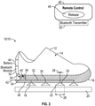
FIG. 2 is a schematic illustration of an embodiment of an immobility device disengaged from a surface; -
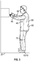
FIG. 3 is a schematic illustration of an operator utilizing an immobility device; and -
FIG. 4 is another schematic illustration of an operator utilizing an immobility device. - A detailed description of one or more embodiments of the disclosed apparatus and method are presented herein by way of exemplification and not limitation with reference to the Figures.
- Referring to
FIG. 1 , illustrated is an embodiment of animmobility device 15, such asshoe 10. WhileFIG. 1 shows the exemplary embodiment of theimmobility device 15 as theshoe 10, one skilled in the art will readily appreciate that theimmobility devices 15 described herein may be utilized at other parts of the body, such as a hand, wrist, or knee, as further discussed with reference toFIG. 4 , for example. - The
shoe 10 includes ashoe body 12 having an upper 14 and a sole 16. A plurality ofsuction cups 18, such as foursuction cups 18 are located at the sole 16. Thesuction cups 18 are formed from a compliant material, such as a rubber or plastic material, to engage asurface 20 such as a floor, wall or the like. Eachsuction cup 18 has afirst end 22 configured to engage thesurface 20, and asecond end 24 opposite thefirst end 22. In some embodiments, thefirst end 22 is circular and has afirst diameter 26. Similarly, thesecond end 24 is circular and has asecond diameter 28 smaller than thefirst diameter 26. Acup air passage 30 extends from thesuction cup 18 into the sole 16, and is connected to amain air passage 32, which extends along the sole 16 to anair inlet 34 located at, for example, aheel portion 36 of the sole 16. - A
solenoid valve 38 is located in the sole 16 and includes avalve piston 40 that, under normal conditions, extends across themain air passage 32 preventingair flow 42 entering theair inlet 34 from reaching thesuction cups 18. In some embodiments, thesolenoid valve 38 is located between theair inlet 34 and afirst suction cup 18 positioned along themain air passage 32 closest to theair inlet 34. - The
solenoid valve 38 is connected to and powered by abattery 44. Operation of thesolenoid valve 38 is controlled by aremote controller 46 utilized by the operator. Theremote controller 46 may include arelease button 48, or the like, and atransmitter 50, such as a Bluetooth transmitter, which communicates with acontroller 52, such as a Bluetooth module located in theshoe 10, in some embodiments in the sole 16. In some embodiments, thetransmitter 50 communicates with thecontroller 52 wirelessly. While a Bluetooth connection is discussed herein, one skilled in the art will readily appreciate that such a connection is merely exemplary, and that any suitable wireless connection between theremote controller 46 and thecontroller 52 at theshoe 10 may be utilized. Thecontroller 52 communicates anactivation signal 54 to energize thesolenoid valve 38 via thebattery 44. As shown inFIG. 1 , thesolenoid valve 38 is normally in a closed position, in which thevalve piston 40 extends across themain air passage 32. When theshoe 10 is pressed against thesurface 20, the gas in thesuction cups 18 is squeezed out, and since theair inlet 34 is blocked due to the closedsolenoid valve 38, thesuction cup 18 can hold to thesurface 20 tightly to prevent movement. - Referring to
FIG. 2 , when the operator needs to move, therelease button 48 is activated and thesolenoid valve 38 is energized, thus retracting thevalve piston 40 from themain air passage 32. This allows theair flow 42 into themain air passage 32 via theair inlet 34 and into thesuction cups 18. The suction cups 18 can then be easily separated from thesurface 20, thus allowing the operator to move. - Referring to
FIGs 3 and4 , shown are different locations on anoperator 60 where theimmobility device 15 may be utilized. InFIG. 3 , theimmobility device 15 is theshoe 10. In other embodiments, such as shown inFIG. 4 , theimmobility device 15 may be utilized as anarm sleeve 62 or, for example, a knee sleeve 64. Further, theremote controller 46 may be hand held, or may further be secured to theoperator 60 at, for example, theforearm 66,torso 68 or the like. In still other embodiments, theremote controller 46 may employ one ormore sensors 70 that detectoperator 60 movement, such as, for example, lifting the leg, double tap using toes, or the like, which transmits the activation signal resulting in opening of thesolenoid valve 38. - The
immobility devices 15 disclosed herein are remote controlled, thereby easy to utilize, and allow for the elimination of typically used foot loops and straps in free-fall environments. Further, this enables utilization of theimmobility device 15 at any needed location, even locations where foot loops or straps typically not installed. - The term "about" is intended to include the degree of error associated with measurement of the particular quantity based upon the equipment available at the time of filing the application.
- The terminology used herein is for the purpose of describing particular embodiments only and is not intended to be limiting of the present disclosure. As used herein, the singular forms "a", "an" and "the" are intended to include the plural forms as well, unless the context clearly indicates otherwise. It will be further understood that the terms "comprises" and/or "comprising," when used in this specification, specify the presence of stated features, integers, steps, operations, elements, and/or components, but do not preclude the presence or addition of one or more other features, integers, steps, operations, element components, and/or groups thereof.
- While the present disclosure has been described with reference to an exemplary embodiment or embodiments, it will be understood by those skilled in the art that various changes may be made without departing from the scope of the invention as defined by the claims. In addition, many modifications may be made to adapt a particular situation or material to the teachings of the present disclosure without departing from the scope of the claims. Therefore, it is intended that the present disclosure not be limited to the particular embodiment disclosed as the best mode contemplated for carrying out this present disclosure, but that the present disclosure will include all embodiments falling within the scope of the claims.
Claims (13)
- An immobility system for a free-fall environment, comprising:
an immobility device (15), comprising:at least one suction cup (18) configured to engage the immobility device to a surface (20);a valve (38) that, when activated, results in release of the at least one suction cup from engagement with the surface; anda remote controller (46) spaced apart from the valve, configured to selectably transmit an activation signal to the valve. - The immobility system of claim 1, further comprising:a receiver (52) disposed at the immobility device and operably connected to the valve; anda transmitter (50) disposed in the remote controller and wirelessly connected to the receiver;wherein the receiver receives the activation signal from the transmitter and activates operation of the valve.
- The immobility system of claim 2, wherein the transmitter communicates with the receiver via Bluetooth®.
- The immobility system of claim 1, 2 or 3, wherein the remote controller includes one or more sensors (70) that detect operator movement and transmit the activation signal.
- An immobility device, comprising:at least one suction cup (18) configured to engage the immobility device to a surface;a valve (38) that, when activated, results in release of the at least one suction cup from engagement with the surface; anda receiver (52) configured to receive an activation signal and activate the valve.
- The immobility system or device of any of the preceding claims, further comprising an air passage (32) extending from the at least one suction cup, the air passage including an air inlet opening (34);
wherein the valve includes a valve piston (40) movable from a deactivated position in which the valve piston blocks the air passage between the air inlet and the at least one suction cup, and an activated position at which the valve piston does not block the air passage thereby allowing an airflow through the air passage to the at least one suction cup. - The immobility system or device of claim 6, wherein the valve is a solenoid valve.
- The immobility system or device of claim 6 or 7, further comprising a battery (44) operably connected to the valve.
- The immobility system or device of any preceding claim, wherein the receiver receives the activation signal wirelessly.
- The immobility system or device of any preceding claim, wherein the immobility device is a shoe (10).
- The immobility system or device of claim 10, wherein the at least one suction cup (18) is disposed at a sole (16) of the shoe.
- The immobility system or device of claim 11, wherein the at least one suction cup is connected to an air inlet via at least one air passage extending through the sole.
- The immobility system or device of any of claims 1 to 9, wherein the immobility device is one of an arm sleeve (62) or a knee sleeve (64).
Applications Claiming Priority (1)
| Application Number | Priority Date | Filing Date | Title |
|---|---|---|---|
| IN202011031722 | 2020-07-24 |
Publications (1)
| Publication Number | Publication Date |
|---|---|
| EP3942955A1 true EP3942955A1 (en) | 2022-01-26 |
Family
ID=77042736
Family Applications (1)
| Application Number | Title | Priority Date | Filing Date |
|---|---|---|---|
| EP21187264.3A Withdrawn EP3942955A1 (en) | 2020-07-24 | 2021-07-22 | Suction apparatus for immobility in free fall |
Country Status (2)
| Country | Link |
|---|---|
| US (1) | US11680600B2 (en) |
| EP (1) | EP3942955A1 (en) |
Families Citing this family (1)
| Publication number | Priority date | Publication date | Assignee | Title |
|---|---|---|---|---|
| CN219827439U (en) * | 2023-05-30 | 2023-10-13 | 深圳市铁头科技有限公司 | Sucking disc pneumatic control system and photographic equipment |
Citations (4)
| Publication number | Priority date | Publication date | Assignee | Title |
|---|---|---|---|---|
| US6470600B1 (en) * | 2001-06-01 | 2002-10-29 | Timothy Louie | Martial arts shoe |
| KR100741628B1 (en) * | 2007-02-07 | 2007-07-23 | 양희운 | Impact of shock-absorbing shoes of circular air |
| US20160128399A1 (en) * | 2013-06-13 | 2016-05-12 | The Board Of Trustees Of The University Of Illinois | Surgical suit |
| US20190063488A1 (en) * | 2017-08-23 | 2019-02-28 | Todd H. Becker | Electronically-releasable suction cup assembly secured to an appliance |
Family Cites Families (8)
| Publication number | Priority date | Publication date | Assignee | Title |
|---|---|---|---|---|
| US1389416A (en) | 1920-08-13 | 1921-08-30 | Zertuche Jose Garza | Non-slip device |
| US1634196A (en) * | 1927-01-17 | 1927-06-28 | Jones Lewis | Sheet piler |
| DE1236755B (en) * | 1963-05-21 | 1967-03-16 | Hasenclever Ag Maschf | Device for lifting particularly flat material with a suction head designed as a cylinder-piston arrangement |
| US4118878A (en) | 1977-09-27 | 1978-10-10 | Semon William P | Article of footwear |
| US4674200A (en) | 1985-12-12 | 1987-06-23 | Peter Sing | Slip resistant footwear |
| CN100528020C (en) | 2007-12-14 | 2009-08-19 | 蓝劲松 | Suction Cup Bionic Shoes |
| TWM602185U (en) * | 2020-06-30 | 2020-10-01 | 陳國章 | Rotary closed air valve type vacuum adsorption device |
| US12167770B2 (en) * | 2020-10-07 | 2024-12-17 | Reebok International Limited | Vacuum pump assembly for article of footwear |
-
2021
- 2021-01-27 US US17/159,280 patent/US11680600B2/en active Active
- 2021-07-22 EP EP21187264.3A patent/EP3942955A1/en not_active Withdrawn
Patent Citations (4)
| Publication number | Priority date | Publication date | Assignee | Title |
|---|---|---|---|---|
| US6470600B1 (en) * | 2001-06-01 | 2002-10-29 | Timothy Louie | Martial arts shoe |
| KR100741628B1 (en) * | 2007-02-07 | 2007-07-23 | 양희운 | Impact of shock-absorbing shoes of circular air |
| US20160128399A1 (en) * | 2013-06-13 | 2016-05-12 | The Board Of Trustees Of The University Of Illinois | Surgical suit |
| US20190063488A1 (en) * | 2017-08-23 | 2019-02-28 | Todd H. Becker | Electronically-releasable suction cup assembly secured to an appliance |
Non-Patent Citations (1)
| Title |
|---|
| ANONYMOUS: "Vacuum-powered suction pads enable wall-climbing | CBC News", 13 June 2012 (2012-06-13), XP055870826, Retrieved from the Internet <URL:https://www.cbc.ca/news/science/vacuum-powered-suction-pads-enable-wall-climbing-1.1171542> [retrieved on 20211208] * |
Also Published As
| Publication number | Publication date |
|---|---|
| US11680600B2 (en) | 2023-06-20 |
| US20220025921A1 (en) | 2022-01-27 |
Similar Documents
| Publication | Publication Date | Title |
|---|---|---|
| US12048667B2 (en) | Use of a leg support exoskeleton | |
| US11680600B2 (en) | Suction apparatus for immobility in free fall | |
| US4236725A (en) | Dynamic device for holding the foot and the leg in position in a rigid structure | |
| US6321770B1 (en) | Regulator valve for escape slide | |
| US8608112B1 (en) | Modular programmable electronic initiation device for parachute disreefing or disconnect | |
| EP3505445A1 (en) | Manipulation system and method for an aircraft | |
| US20190168706A1 (en) | Locking harness | |
| US20210106341A1 (en) | Wearable emergency hemorrhage cessation device | |
| EP3422155A1 (en) | Object controller | |
| JP2018061663A (en) | Power assisting robot device | |
| US20070191881A1 (en) | Tourniquet | |
| US7137481B2 (en) | Fall arrest device with locking roller | |
| EP3443547B1 (en) | Fall detection system | |
| EP3421100B1 (en) | Harness for breathing apparatus | |
| EP3020982B1 (en) | Actuator utilizing pneumatic muscles | |
| US3456642A (en) | Demand actuating means for alternate breathing supply | |
| US6708708B2 (en) | Pneumatic actuation control system and method of operation | |
| JPWO2017110930A1 (en) | Performance evaluation apparatus and performance evaluation method for wearable motion assist device | |
| EP4323303A1 (en) | Implementing an emergency stopping break for hoist systems | |
| US3826156A (en) | Secured air reserve system | |
| US20230190565A1 (en) | System for assisting muscle strength | |
| KR100673523B1 (en) | Parafoil guided parachute transportation system | |
| US2940701A (en) | Personnel escape equipment | |
| BR102012029193B1 (en) | non-destructive inspection device having an ergonomic grip and associated method | |
| CN107085366A (en) | Climbing speed indicating mechanism and the underwater watch including the mechanism |
Legal Events
| Date | Code | Title | Description |
|---|---|---|---|
| PUAI | Public reference made under article 153(3) epc to a published international application that has entered the european phase |
Free format text: ORIGINAL CODE: 0009012 |
|
| STAA | Information on the status of an ep patent application or granted ep patent |
Free format text: STATUS: THE APPLICATION HAS BEEN PUBLISHED |
|
| AK | Designated contracting states |
Kind code of ref document: A1 Designated state(s): AL AT BE BG CH CY CZ DE DK EE ES FI FR GB GR HR HU IE IS IT LI LT LU LV MC MK MT NL NO PL PT RO RS SE SI SK SM TR |
|
| STAA | Information on the status of an ep patent application or granted ep patent |
Free format text: STATUS: REQUEST FOR EXAMINATION WAS MADE |
|
| 17P | Request for examination filed |
Effective date: 20220726 |
|
| RBV | Designated contracting states (corrected) |
Designated state(s): AL AT BE BG CH CY CZ DE DK EE ES FI FR GB GR HR HU IE IS IT LI LT LU LV MC MK MT NL NO PL PT RO RS SE SI SK SM TR |
|
| REG | Reference to a national code |
Ref country code: DE Ref legal event code: R079 Free format text: PREVIOUS MAIN CLASS: A43B0003000000 Ipc: A43B0007083000 |
|
| RIC1 | Information provided on ipc code assigned before grant |
Ipc: A43B 7/08 20220101ALI20240626BHEP Ipc: A43B 3/00 20220101ALI20240626BHEP Ipc: A43B 3/24 20060101ALI20240626BHEP Ipc: A43B 13/20 20060101ALI20240626BHEP Ipc: F16B 47/00 20060101ALI20240626BHEP Ipc: B64G 1/60 20060101ALI20240626BHEP Ipc: B64G 6/00 20060101ALI20240626BHEP Ipc: A43B 3/40 20220101ALI20240626BHEP Ipc: A43B 3/34 20220101ALI20240626BHEP Ipc: A43B 3/48 20220101ALI20240626BHEP Ipc: A43B 13/14 20060101ALI20240626BHEP Ipc: A43B 7/083 20220101AFI20240626BHEP |
|
| GRAP | Despatch of communication of intention to grant a patent |
Free format text: ORIGINAL CODE: EPIDOSNIGR1 |
|
| STAA | Information on the status of an ep patent application or granted ep patent |
Free format text: STATUS: GRANT OF PATENT IS INTENDED |
|
| INTG | Intention to grant announced |
Effective date: 20240802 |
|
| STAA | Information on the status of an ep patent application or granted ep patent |
Free format text: STATUS: THE APPLICATION IS DEEMED TO BE WITHDRAWN |
|
| 18D | Application deemed to be withdrawn |
Effective date: 20241203 |