EP3942911A1 - Air distribution system and method for operating such - Google Patents
Air distribution system and method for operating such Download PDFInfo
- Publication number
- EP3942911A1 EP3942911A1 EP21183938.6A EP21183938A EP3942911A1 EP 3942911 A1 EP3942911 A1 EP 3942911A1 EP 21183938 A EP21183938 A EP 21183938A EP 3942911 A1 EP3942911 A1 EP 3942911A1
- Authority
- EP
- European Patent Office
- Prior art keywords
- distribution
- agricultural product
- diverter valve
- shell
- pipe
- Prior art date
- Legal status (The legal status is an assumption and is not a legal conclusion. Google has not performed a legal analysis and makes no representation as to the accuracy of the status listed.)
- Granted
Links
Images




Classifications
-
- A—HUMAN NECESSITIES
- A01—AGRICULTURE; FORESTRY; ANIMAL HUSBANDRY; HUNTING; TRAPPING; FISHING
- A01C—PLANTING; SOWING; FERTILISING
- A01C15/00—Fertiliser distributors
- A01C15/003—Bulk fertiliser or grain handling in the field or on the farm
-
- A—HUMAN NECESSITIES
- A01—AGRICULTURE; FORESTRY; ANIMAL HUSBANDRY; HUNTING; TRAPPING; FISHING
- A01C—PLANTING; SOWING; FERTILISING
- A01C7/00—Sowing
- A01C7/08—Broadcast seeders; Seeders depositing seeds in rows
- A01C7/081—Seeders depositing seeds in rows using pneumatic means
-
- A—HUMAN NECESSITIES
- A01—AGRICULTURE; FORESTRY; ANIMAL HUSBANDRY; HUNTING; TRAPPING; FISHING
- A01C—PLANTING; SOWING; FERTILISING
- A01C15/00—Fertiliser distributors
- A01C15/005—Undercarriages, tanks, hoppers, stirrers specially adapted for seeders or fertiliser distributors
- A01C15/006—Hoppers
-
- A—HUMAN NECESSITIES
- A01—AGRICULTURE; FORESTRY; ANIMAL HUSBANDRY; HUNTING; TRAPPING; FISHING
- A01C—PLANTING; SOWING; FERTILISING
- A01C15/00—Fertiliser distributors
- A01C15/04—Fertiliser distributors using blowers
-
- A—HUMAN NECESSITIES
- A01—AGRICULTURE; FORESTRY; ANIMAL HUSBANDRY; HUNTING; TRAPPING; FISHING
- A01C—PLANTING; SOWING; FERTILISING
- A01C7/00—Sowing
- A01C7/08—Broadcast seeders; Seeders depositing seeds in rows
- A01C7/081—Seeders depositing seeds in rows using pneumatic means
- A01C7/084—Pneumatic distribution heads for seeders
-
- B—PERFORMING OPERATIONS; TRANSPORTING
- B65—CONVEYING; PACKING; STORING; HANDLING THIN OR FILAMENTARY MATERIAL
- B65G—TRANSPORT OR STORAGE DEVICES, e.g. CONVEYORS FOR LOADING OR TIPPING, SHOP CONVEYOR SYSTEMS OR PNEUMATIC TUBE CONVEYORS
- B65G53/00—Conveying materials in bulk through troughs, pipes or tubes by floating the materials or by flow of gas, liquid or foam
- B65G53/04—Conveying materials in bulk pneumatically through pipes or tubes; Air slides
-
- B—PERFORMING OPERATIONS; TRANSPORTING
- B65—CONVEYING; PACKING; STORING; HANDLING THIN OR FILAMENTARY MATERIAL
- B65G—TRANSPORT OR STORAGE DEVICES, e.g. CONVEYORS FOR LOADING OR TIPPING, SHOP CONVEYOR SYSTEMS OR PNEUMATIC TUBE CONVEYORS
- B65G53/00—Conveying materials in bulk through troughs, pipes or tubes by floating the materials or by flow of gas, liquid or foam
- B65G53/34—Details
- B65G53/40—Feeding or discharging devices
- B65G53/46—Gates or sluices, e.g. rotary wheels
-
- F—MECHANICAL ENGINEERING; LIGHTING; HEATING; WEAPONS; BLASTING
- F16—ENGINEERING ELEMENTS AND UNITS; GENERAL MEASURES FOR PRODUCING AND MAINTAINING EFFECTIVE FUNCTIONING OF MACHINES OR INSTALLATIONS; THERMAL INSULATION IN GENERAL
- F16K—VALVES; TAPS; COCKS; ACTUATING-FLOATS; DEVICES FOR VENTING OR AERATING
- F16K11/00—Multiple-way valves, e.g. mixing valves; Pipe fittings incorporating such valves
- F16K11/02—Multiple-way valves, e.g. mixing valves; Pipe fittings incorporating such valves with all movable sealing faces moving as one unit
- F16K11/06—Multiple-way valves, e.g. mixing valves; Pipe fittings incorporating such valves with all movable sealing faces moving as one unit comprising only sliding valves, i.e. sliding closure elements
- F16K11/065—Multiple-way valves, e.g. mixing valves; Pipe fittings incorporating such valves with all movable sealing faces moving as one unit comprising only sliding valves, i.e. sliding closure elements with linearly sliding closure members
- F16K11/07—Multiple-way valves, e.g. mixing valves; Pipe fittings incorporating such valves with all movable sealing faces moving as one unit comprising only sliding valves, i.e. sliding closure elements with linearly sliding closure members with cylindrical slides
-
- F—MECHANICAL ENGINEERING; LIGHTING; HEATING; WEAPONS; BLASTING
- F16—ENGINEERING ELEMENTS AND UNITS; GENERAL MEASURES FOR PRODUCING AND MAINTAINING EFFECTIVE FUNCTIONING OF MACHINES OR INSTALLATIONS; THERMAL INSULATION IN GENERAL
- F16K—VALVES; TAPS; COCKS; ACTUATING-FLOATS; DEVICES FOR VENTING OR AERATING
- F16K31/00—Actuating devices; Operating means; Releasing devices
- F16K31/44—Mechanical actuating means
- F16K31/60—Handles
-
- A—HUMAN NECESSITIES
- A01—AGRICULTURE; FORESTRY; ANIMAL HUSBANDRY; HUNTING; TRAPPING; FISHING
- A01C—PLANTING; SOWING; FERTILISING
- A01C7/00—Sowing
- A01C7/08—Broadcast seeders; Seeders depositing seeds in rows
- A01C7/10—Devices for adjusting the seed-box ; Regulation of machines for depositing quantities at intervals
- A01C7/107—Calibration of the seed rate
-
- B—PERFORMING OPERATIONS; TRANSPORTING
- B65—CONVEYING; PACKING; STORING; HANDLING THIN OR FILAMENTARY MATERIAL
- B65G—TRANSPORT OR STORAGE DEVICES, e.g. CONVEYORS FOR LOADING OR TIPPING, SHOP CONVEYOR SYSTEMS OR PNEUMATIC TUBE CONVEYORS
- B65G2812/00—Indexing codes relating to the kind or type of conveyors
- B65G2812/16—Pneumatic conveyors
- B65G2812/1608—Pneumatic conveyors for bulk material
- B65G2812/1616—Common means for pneumatic conveyors
- B65G2812/1625—Feeding or discharging means
-
- B—PERFORMING OPERATIONS; TRANSPORTING
- B65—CONVEYING; PACKING; STORING; HANDLING THIN OR FILAMENTARY MATERIAL
- B65G—TRANSPORT OR STORAGE DEVICES, e.g. CONVEYORS FOR LOADING OR TIPPING, SHOP CONVEYOR SYSTEMS OR PNEUMATIC TUBE CONVEYORS
- B65G53/00—Conveying materials in bulk through troughs, pipes or tubes by floating the materials or by flow of gas, liquid or foam
- B65G53/34—Details
- B65G53/36—Arrangements of containers
Definitions
- the present disclosure generally relates to agricultural equipment, and more particularly but not exclusively relates to the distribution of agricultural products.
- Air distributor systems are commonly mounted on agricultural equipment (e.g., tractors and/or trailers) to distribute agricultural products, such as seed, pesticides, and/or fertilizers.
- the agricultural product is typically stored in a reservoir and distributed to the distribution tower via a distribution line.
- One issue that can arise with such systems relates to the extraction of excess product from the reservoir. For these reasons among others, there remains a need for further improvements in this technological field.
- An exemplary diverter valve generally includes a shell, a pipe, and a handle.
- the shell includes a body extending in a longitudinal direction, a shell inlet port, a shell outlet port, and a positioning slot formed in the body.
- the pipe is seated in the body for sliding movement in the longitudinal direction, and includes a first passage and a second passage.
- the handle is connected to the pipe through the positioning slot, and is operable to move the pipe relative to the shell between a first position in which the shell inlet port is connected with the shell outlet port via the first passage, and a second position in which the second passage is connected with the shell inlet port and the shell outlet port is disconnected from the second passage.
- references in the specification to "one embodiment,” “an embodiment,” “an illustrative embodiment,” etc., indicate that the embodiment described may include a particular feature, structure, or characteristic, but every embodiment may or may not necessarily include that particular feature, structure, or characteristic. Moreover, such phrases are not necessarily referring to the same embodiment. It should further be appreciated that although reference to a "preferred" component or feature may indicate the desirability of a particular component or feature with respect to an embodiment, the disclosure is not so limiting with respect to other embodiments, which may omit such a component or feature.
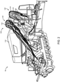
- the agricultural equipment 90 including an air distribution system 100 according to certain embodiments.
- the agricultural equipment 90 generally includes a tractor 92 and a trailer 94 coupled with the tractor 92 such that the tractor 92 is operable to tow the trailer 94 across and through a plot of land.
- the air distribution system 100 is mounted to the trailer 94. It is also contemplated that at least a portion of the air distribution system 100 may be mounted to the tractor 92.
- the air distribution system 100 generally includes a reservoir 110 operable to store an agricultural product 102, a distribution tower 120 operable to distribute the agricultural product 102, a distribution line 130 connecting the reservoir 110 with the distribution tower 120, and a blower 140 that facilitates movement of the agricultural product 102 from the reservoir 110 to the distribution tower 120, and may further include a meter 150 that regulates the discharge of the agricultural product 102 from the reservoir 110.
- the system 100 further includes a diverter valve 200 that aids in selectively diverting agricultural product 102 to a discharge line 190 to facilitate collection of excess agricultural product 102 from within the reservoir 110.
- the reservoir 110 is operable to store the agricultural product 102, and to discharge the agricultural product 102 to the distribution line 130, for example via the meter 150.
- the agricultural product 102 may, for example, comprise one or more of seed, pesticide, fertilizer, or another granular or pelletized form of agricultural product.
- the agricultural product 102 may be discharged to the distribution line 130 entirely or primarily under the force of gravity.
- the reservoir 110 may be connected with the blower 140 via a pressure conduit 104 such that a portion of the air discharged by the blower 140 is diverted to the reservoir 110, thereby facilitating the discharge of agricultural product 102 to the distribution line 130.
- the pressure conduit 104 may include a valve 105 having an open state in which a portion of the air discharged from the blower 140 is directed into the reservoir 110, and a closed state in which the blower 140 does not discharge air into the reservoir 110.
- the distribution tower 120 generally includes an inlet 122 operable to receive the agricultural product 102 via the distribution valve 200, one or more outlets 124 operable to distribute the agricultural product 102, and a header 126 configured to distribute agricultural product from the inlet 122 to the one or more outlets 124.
- Such distribution towers are known in the art, and need not be described in further detail herein.
- the distribution line 130 generally includes a manifold 132 connected with the reservoir 110 and the blower 140, and a distribution conduit 139 leading from the manifold 132 to the diverter valve 200.
- the manifold 132 includes a product inlet 133 that receives product 102 from the reservoir 110, an air inlet 134 that receives air discharged by the blower 140, and an outlet 135 connected with the distribution conduit 139.
- the manifold 132 is configured to mix the received product 102 with the air discharged by the blower 140 such that the product 102 becomes at least partially entrained in the air and flows toward the diverter valve 200 along with the flowing air.
- the product inlet 133 may be selectively connected with the reservoir 110 via a bypass line 106 that bypasses the meter 150.
- a bypass line 106 may include a valve 107 having an open state in which the product 102 is operable to bypass the meter 150 and a closed state in which the product 102 must pass through the meter 150 in order to enter the manifold 132.
- the blower 140 is configured to discharge air via a plenum 142 at a pressure and flow rate sufficient to move the product 102 along the distribution line 130 and toward the diverter valve 200.
- the plenum 142 is connected with the air inlet 134 of the manifold 132 such that the blower 140 is operable to discharge air into the manifold 132.
- the plenum 142 may further be at least selectively connected with the reservoir 110, for example via a pressure line 104, such that the blower 140 is at least selectively operable to discharge air into the reservoir 110 along the lines set forth above.
- the meter 150 is connected between the reservoir 110 and the manifold 132, and is configured to regulate the rate at which product 102 is discharged from the reservoir 110 to the manifold 132.
- the meter 150 may, for example, comprise a rotatable drum 152 having pockets operable to receive relatively small quantities of the product 102 from the reservoir 110. As the drum 152 rotates, the product 102 falls from the pockets into the product inlet 133 of the manifold 132. The rotational speed of the drum 152 may be variable to control the rate at which product 102 is discharged from the reservoir 110 to the manifold 130.
- the drum 152 may be removable such that when the drum 152 is removed, the product 102 is free to fall into the manifold 132 in an unmetered manner. In order to provide for unmetered flow, it may also be desirable to provide the meter 150 with a blank cartridge similar to the drum 152, where the blank cartridge provides for unmetered flow of product 102.
- the rate of flow of product to the diverter valve 200 in the illustrated system 100 can be regulated in several manners.
- the rate at which the product 102 flows toward the valve 200 may be adjusted by regulating the operating speed of the meter 150.
- the rate at which the product flows toward the valve 200 may be adjusted by adjusting the degree to which the bypass valve 107 is open, thereby providing a higher or lower flow rate through the valve 107.
- the flow rate for the product 102 may be adjusted by adjusting the degree to which the pressure valve 105 is open, thereby adjusting the pressure within the reservoir 110.
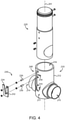
- the diverter valve 200 generally includes a shell 210, a pipe 220 slidably mounted in the shell 210, and a handle 230 that facilitates movement of the pipe 220 relative to the shell 210 to adjust the diverter valve 200 between a first state and a second state.
- the diverter valve 200 is configured to discharge product 102 to the distribution tower 120 when in a normal operating state, and to discharge product 102 to the discharge line 190 when in a discharge state.
- the shell 210 generally includes a hollow body 212 extending along a longitudinal axis 201 of the valve 200, a shell intake port 214 formed on one side of the body 212, a first shell outlet port 215 formed on an opposite side of the body 212, and a second shell outlet port 216 offset from the inlet port 214 and the first outlet port 215.
- the body 212 also defines a positioning slot 240, which aids in transitioning the diverter valve 200 between its normal operating state and its discharge state as described in further detail below.
- the shell 210 may further include indicia 217 relating to the normal operating state and the discharge state.
- the pipe 220 is slidably mounted in the body 212 of the shell 210, and generally includes a first pipe inlet 222, a first pipe outlet 224 connected with the first pipe inlet 222 via a first passage 223, a second pipe inlet 226, and a second pipe outlet 228 connected with the second pipe inlet 226 via a second passage 227.
- the first passage 223 may be considered to include the first inlet 222 and the first outlet 224
- the second passage 227 may be considered to include the second inlet 226 and the second outlet 228.
- the first passage 223 and the second passage 227 are isolated from one another such that product 102 entering the pipe 220 via the inlet 222/226 of one passage 223/227 exits the pipe 220 via the outlet 224/228 of the same passage 223/227.
- Formed about the second outlet 228 is a set of threads 229 that may, for example, be used to facilitate connection of the pipe 220 with the discharge line 190.
- the pipe 220 is configured to selectively connect the shell inlet port 214 with each of the shell outlet ports 215, 216.
- the handle 230 generally includes a base portion 232 and a grip portion 234 extending from the base portion 232.
- the base portion 232 is coupled with the pipe 220 such that a portion of the shell 210 is captured between the pipe 220 and the handle 230.
- a pair of posts 236 or fasteners may extend through the positioning slot 240 such that the handle 230 is coupled to the pipe 220 via the posts 236. While the illustrated handle 230 includes a pair of posts 236, it is also contemplated that more or fewer posts 236 may be utilized.
- the positioning slot 240 is formed in the shell 210, and generally includes a longitudinal portion 242, a first pair of retention slots 244 extending laterally from the longitudinal portion 242, and a second pair of retention slots 246 extending laterally from the longitudinal portion and offset from the first pair of retention slots 244.
- the first retention slots 244 are spaced apart by a distance corresponding to the distance by which the posts 236 are offset from one another such that the first retention slots 244 are operable to receive the posts 236.
- the second retention slots 246 are spaced apart by a distance corresponding to the distance by which the posts 236 are offset from one another such that the second retention slots 246 are operable to receive the posts 236.
- first retention slots 244 are offset from the second retention slots 246 by a distance corresponding to the distance between the centerlines of the first pipe inlet 222 and the second pipe inlet 226.
- the retention slots 244, 246 are configured to selectively retain the pipe 220 in each of a first position corresponding to the first state and a second position corresponding to the second state.
- retention slots 244, 246 are generally perpendicular to the longitudinal portion 242, it is also contemplated that one or more of the retention slots 244, 246 may be provided at an oblique angle relative to the longitudinal portion 242. Additionally, while the illustrated retention slots 244, 246 are generally straight, it is also contemplated that one or more of the retention slots 244, 246 may include a longitudinally-extending jog operable to receive the posts 236. Furthermore, while the first retention slots 244 are formed on the same lateral side of the longitudinal portion 242 as the second retention slots 246, it is also contemplated that the first retention slots 244 may be formed on the opposite lateral side of the longitudinal portion 242 as the second retention slots 246.
- each set of retention slots may include more or fewer than two slots, for example in embodiments in which the handle 230 includes more or fewer than two posts 236.
- the shell inlet port 214 When installed in the system 100, the shell inlet port 214 is connected with the distribution line 139, one of the first shell outlet port 215 or the second pipe outlet 228 is connected with the intake 122 of the distribution tower 120, and the other of the first shell outlet port 215 or the second pipe outlet 228 may be connected with the discharge line 190.
- the first shell outlet port 215 is connected with the distribution tower intake 122 (either directly or via a conduit), and the second pipe outlet 228 is connected with the discharge line 190. It is also contemplated that these connections may be reversed such that the second pipe outlet 228 is connected with the distribution tower intake 122 and the first shell outlet port 215 is connected with the discharge line 190.
- the shell 210 may comprise indicia 217 relating to the position of the pipe 220 and handle 230, and thus to the state of the diverter valve 200.
- the indicia 217 may include a first state indicium 218, and the handle 230 may be nearer to the first state indicium 218 when the handle 230 is in the first position than when the handle 230 is in the second position.
- the first state indicium 218 may indicate that when the handle 230 is in the first position, the valve 200 is in the first state.
- the first state indicium 218 may comprise an arrow pointing in the direction of the first shell outlet 215 to indicate that the agricultural product 102 will flow through the first shell outlet 215 when the handle 230 is in the first position.
- the indicia 217 may include a second state indicium 219, and the handle 230 may be nearer to the second state indicium 219 when the handle 230 is in the second position than when the handle 230 is in the first position.
- the second state indicium 218 may indicate that when the handle 230 is in the first position, the valve 200 is in the second state.
- the second state indicium 218 may comprise an arrow pointing in the direction of the second pipe outlet 228 to indicate that the agricultural product 102 will flow through the second pipe outlet 228 when the handle 230 is in the second position.
- the diverter valve 200 has a first state and a second state, each of which corresponds to a respective position of the pipe 220 relative to the shell 210. More particularly, the diverter valve 200 has a first state ( Fig. 7 ) in which the pipe 220 is in a first position relative to the shell 210, and a second state ( Fig. 8 ) in which the pipe 220 is in a second position relative to the shell 210.
- the first state ( Fig. 7 ) is the normal operating state, in which product 102 flows to the distribution tower 120
- the second state ( Fig. 8 ) is the discharge state, in which product 102 flows to a discharge port (e.g., via the discharge line 190).
- first and second states may be reversed.
- the first state Fig. 7
- the second state Fig. 8
- the first pipe inlet 222 is aligned with the shell inlet port 214, and the first pipe outlet 224 is aligned with the first shell outlet 215 such that the shell inlet port 214 and the first shell outlet 215 are connected via the first passage 223.
- product 102 flowing into the valve 200 will be directed to the component connected with the first shell outlet 215.
- the component connected with the first shell outlet 215 is the distribution tower 120 such that the first state is the normal operating state.
- the first state indicium 218 may be adjacent to the handle 230 to thereby indicate to the user that the agricultural product 102 will flow through the first shell outlet 215 and onward to the component connected with the first shell outlet (e.g., the distribution tower 120).
- the second pipe inlet 226 is aligned with the shell inlet port 214.
- product 102 flowing into the valve 200 will be directed to the component connected with the second pipe outlet 228.
- the component connected with the second pipe outlet 228 is the discharge line 190 such that the second state is the discharge state.
- the second state indicium 218 may be adjacent to the handle 230 to thereby indicate to the user that the agricultural product 102 will flow through the second pipe outlet 228.
- valve 200 When the valve 200 is in its first state, the handle 230 is in its first position, in which the posts 236 are received in the first retention slots 244. Conversely, when the valve 200 is in its second state, the handle 230 is in its second position, in which the posts 236 are received in the second retention slots 246.
- the valve 200 may be adjusted between the first state and the second state by manipulation of the handle 230. For example, when the valve 200 is in its first state, a user may shift the handle 230 laterally such that the posts 236 enter the longitudinal portion 242 of the positioning slot 240.
- FIG. 9 an exemplary process 300 that may be performed using the air distribution system 100 is illustrated. Blocks illustrated for the processes in the present application are understood to be examples only, and blocks may be combined or divided, and added or removed, as well as re-ordered in whole or in part, unless explicitly stated to the contrary. Additionally, while the blocks are illustrated in a relatively serial fashion, it is to be understood that two or more of the blocks may be performed concurrently or in parallel with one another. Moreover, while the process 300 is described herein with specific reference to the air distribution system 100 illustrated in Figs. 1-3 and the diverter valve 200 illustrated in Figs. 4-8 , it is to be appreciated that the process 300 may be performed with air distribution systems and/or diverter valves having additional or alternative features.
- the process 300 may begin with block 310, which generally involves placing agricultural product 102 in the reservoir 110.
- the agricultural product 102 may, for example, comprise one or more of seed, fertilizer, pesticide, and/or another form of granular or pelletized agricultural product.
- the process 300 includes block 320, which generally involves directing agricultural product 102 from the reservoir 110 to the distribution line 130.
- block 320 may involve directing the product 102 from the reservoir 110 to the distribution line 130 in a metered manner (e.g., using the meter 150), or may involve directing the product 102 from the reservoir 110 to the distribution line in an unmetered manner (e.g., by removing the drum 152 and/or utilizing the bypass line 106).
- the process 300 further includes block 330, which generally involves operating the blower 140 to urge the agricultural product 102 in the distribution line 130 toward the diverter valve 200.
- the output of the blower 140 is sufficient to at least partially entrain the agricultural product 102 such that the agricultural product 102 flows with the air output by the blower 140 toward the diverter valve 200.
- the blower 140 may further be connected with the reservoir 110 to pressurize the reservoir 110 and aid in urging the product 102 in the reservoir 110 toward the product intake 133 of the distribution line manifold 132. It is also contemplated that the blower 140 may not necessarily be connected with the reservoir 110 via a pressure line 104.
- the process 300 further includes block 340, which generally involves operating the system 100 in a normal operating mode. More particularly, block 340 involves operating the system 100 with the diverter valve 200 in its normal operating state.
- the first shell outlet port 215 is connected with the distribution tower 120 such that the first state ( Fig. 7 ) is the normal operating state.
- the second pipe outlet 228 may be connected with the distribution tower 120 such that the second state ( Fig. 8 ) is the normal operating state.
- block 340 may further include additional operations, such as continuing to perform blocks 320 and 330.
- performance of block 320 may involve directing the product 102 from the reservoir 110 to the distribution line 130 in a metered manner (e.g., by operating the meter 150 to regulate the flowrate of product 102 into the manifold 132).
- block 340 may involve operating the agricultural equipment 90 to which the system 100 is mounted in order to distribute the agricultural product 102 across a plot of land.
- the normal distribution of the agricultural product 102 is no longer desired.
- a first portion of the plot of land has been provided with a first type of agricultural product 102 (e.g., a first type of seed)
- a second portion of the plot of land is now to be provided with a second type of agricultural product 102 (e.g., a second type of seed).
- the plot of land has been seeded, and is now to be provided with fertilizer and/or pesticide. Regardless of the reasons, it may be desirable to empty the reservoir 110 of the remaining agricultural product 102 in a manner that facilitates collection of the product 102 for later use. In such a case, the process 300 may proceed to block 350.
- Block 350 generally involves transitioning from the operating mode to the discharge mode. More particularly, block 350 involves moving the diverter valve 200 from the normal operating state to the discharge state by manipulating the handle 230 in the manner described above. It may be the case that moving the diverter valve 200 between states is more easily accomplished when product 102 is not flowing through the valve 200. In such cases, block 350 may include temporarily halting the flow of product 102 through the valve 200, for example by pausing the blower 140 and/or the meter 150. Block 350 may further involve connecting a discharge line 190 to the second pipe outlet 228 (e.g., by using the threading 229), thereby connecting the reservoir 110 with the discharge line 190 via the distribution line 130 and the diverter valve 200.
- block 350 may further include removing the drum 152 from the meter 150 such that the meter 150 does not restrict the flow of the product 102 from the reservoir 110 into the manifold 132.
- the drum 152 may be replaced with a blank cartridge that does not significantly inhibit flow of product 102 through the meter 150.
- block 350 may include opening the bypass valve 107 such that the product 102 is able to bypass the meter 150 via the bypass line 106.
- performing block 320 in block 360 may involve directing the product 102 from the reservoir 110 to the distribution line 130 in an unmetered manner (e.g., by passing the product 102 through the meter 150 with the drum 152 removed and/or by passing the product 102 through the bypass line 106). It is also contemplated that performing block 320 in block 360 may involve directing the product 102 from the reservoir 110 to the distribution line 130 in a metered manner.
- the agricultural product 102 When operating in the discharge mode of block 360, the agricultural product 102 is directed to a discharge port of the system 100.
- the discharge port may simply be provided by the diverter valve 200 (e.g., as the first shell outlet port 215 or the second pipe outlet 228).
- the discharge line 190 may be connected to the diverter valve 200 and define the discharge port.
- a bin or other collection device may be placed in the vicinity of the discharge port to collect the discharged product 102 for later use. The process 300 may then begin anew by returning the system 100 to its normal operating mode and placing a new agricultural product 102 in the reservoir 110 at block 310.
- blocks of the illustrated process 300 may be reordered in whole or in part. As one example, it may be the case that it is desirable to operate in the discharge mode of block 360 prior to operating in the operating mode of block 340. For example, it may be desirable to divert the product 102 for easy collection while calibrating the meter 150 prior to distribution of the product 102. In such a case, the process 300 may involve first operating the system 100 in the discharge mode of block 360 while calibrating the meter 150, performing a transitioning similar to that of block 350 to transition the system 100 from the discharge mode to the operating mode, and subsequently operating the system 100 in the operating mode of block 340 to distribute the product 102.
Landscapes
- Life Sciences & Earth Sciences (AREA)
- Engineering & Computer Science (AREA)
- Soil Sciences (AREA)
- Environmental Sciences (AREA)
- Mechanical Engineering (AREA)
- General Engineering & Computer Science (AREA)
- Fertilizing (AREA)
- Catching Or Destruction (AREA)
- Multiple-Way Valves (AREA)
Abstract
Description
- The present disclosure generally relates to agricultural equipment, and more particularly but not exclusively relates to the distribution of agricultural products.
- Air distributor systems are commonly mounted on agricultural equipment (e.g., tractors and/or trailers) to distribute agricultural products, such as seed, pesticides, and/or fertilizers. The agricultural product is typically stored in a reservoir and distributed to the distribution tower via a distribution line. One issue that can arise with such systems relates to the extraction of excess product from the reservoir. For these reasons among others, there remains a need for further improvements in this technological field.
- An exemplary diverter valve generally includes a shell, a pipe, and a handle. The shell includes a body extending in a longitudinal direction, a shell inlet port, a shell outlet port, and a positioning slot formed in the body. The pipe is seated in the body for sliding movement in the longitudinal direction, and includes a first passage and a second passage. The handle is connected to the pipe through the positioning slot, and is operable to move the pipe relative to the shell between a first position in which the shell inlet port is connected with the shell outlet port via the first passage, and a second position in which the second passage is connected with the shell inlet port and the shell outlet port is disconnected from the second passage. Further embodiments, forms, features, and aspects of the present application shall become apparent from the description and figures provided herewith.
-
-
Fig. 1 illustrates agricultural equipment including an air distribution system according to certain embodiments. -
Fig. 2 illustrates the air distribution system mounted to a trailer of the agricultural equipment. -
Fig. 3 is a schematic illustration of an air distribution system including a diverter valve according to certain embodiments. -
Fig. 4 is an exploded assembly view of a diverter valve according to certain embodiments. -
Fig. 5 is a plan view of the diverter valve illustrated inFig. 3 . -
Fig. 6 is a perspective view of the diverter valve illustrated inFig. 3 . -
Fig. 7 is a cross-sectional view of the diverter valve in a first state. -
Fig. 8 is a cross-sectional view of the diverter valve in a second state. -
Fig. 9 is a schematic flow diagram of a process according to certain embodiments. - Although the concepts of the present disclosure are susceptible to various modifications and alternative forms, specific embodiments have been shown by way of example in the drawings and will be described herein in detail. It should be understood, however, that there is no intent to limit the concepts of the present disclosure to the particular forms disclosed, but on the contrary, the intention is to cover all modifications, equivalents, and alternatives consistent with the present disclosure and the appended claims.
- References in the specification to "one embodiment," "an embodiment," "an illustrative embodiment," etc., indicate that the embodiment described may include a particular feature, structure, or characteristic, but every embodiment may or may not necessarily include that particular feature, structure, or characteristic. Moreover, such phrases are not necessarily referring to the same embodiment. It should further be appreciated that although reference to a "preferred" component or feature may indicate the desirability of a particular component or feature with respect to an embodiment, the disclosure is not so limiting with respect to other embodiments, which may omit such a component or feature. Further, when a particular feature, structure, or characteristic is described in connection with an embodiment, it is submitted that it is within the knowledge of one skilled in the art to implement such feature, structure, or characteristic in connection with other embodiments whether or not explicitly described. Additionally, it should be appreciated that items included in a list in the form of "at least one of A, B, and C" can mean (A); (B); (C); (A and B); (B and C); (A and C); or (A, B, and C). Similarly, items listed in the form of "at least one of A, B, or C" can mean (A); (B); (C); (A and B); (B and C); (A and C); or (A, B, and C). Items listed in the form of "A, B, and/or C" can also mean (A); (B); (C); (A and B); (B and C); (A and C); or (A, B, and C). Further, with respect to the claims, the use of words and phrases such as "a," "an," "at least one," and/or "at least one portion" should not be interpreted so as to be limiting to only one such element unless specifically stated to the contrary, and the use of phrases such as "at least a portion" and/or "a portion" should be interpreted as encompassing both embodiments including only a portion of such element and embodiments including the entirety of such element unless specifically stated to the contrary.
- In the drawings, some structural or method features may be shown in certain specific arrangements and/or orderings. However, it should be appreciated that such specific arrangements and/or orderings may not necessarily be required. Rather, in some embodiments, such features may be arranged in a different manner and/or order than shown in the illustrative figures unless indicated to the contrary. Additionally, the inclusion of a structural or method feature in a particular figure is not meant to imply that such feature is required in all embodiments and, in some embodiments, may be omitted or may be combined with other features.
- With reference to
Figs. 1 and2 , illustrated therein isagricultural equipment 90 including anair distribution system 100 according to certain embodiments. Theagricultural equipment 90 generally includes atractor 92 and atrailer 94 coupled with thetractor 92 such that thetractor 92 is operable to tow thetrailer 94 across and through a plot of land. In the illustrated form, theair distribution system 100 is mounted to thetrailer 94. It is also contemplated that at least a portion of theair distribution system 100 may be mounted to thetractor 92. - With additional reference to
Fig. 3 , theair distribution system 100 generally includes areservoir 110 operable to store anagricultural product 102, adistribution tower 120 operable to distribute theagricultural product 102, adistribution line 130 connecting thereservoir 110 with thedistribution tower 120, and ablower 140 that facilitates movement of theagricultural product 102 from thereservoir 110 to thedistribution tower 120, and may further include ameter 150 that regulates the discharge of theagricultural product 102 from thereservoir 110. As described herein, thesystem 100 further includes adiverter valve 200 that aids in selectively divertingagricultural product 102 to adischarge line 190 to facilitate collection of excessagricultural product 102 from within thereservoir 110. - The
reservoir 110 is operable to store theagricultural product 102, and to discharge theagricultural product 102 to thedistribution line 130, for example via themeter 150. Theagricultural product 102 may, for example, comprise one or more of seed, pesticide, fertilizer, or another granular or pelletized form of agricultural product. In certain embodiments, theagricultural product 102 may be discharged to thedistribution line 130 entirely or primarily under the force of gravity. In certain embodiments, thereservoir 110 may be connected with theblower 140 via apressure conduit 104 such that a portion of the air discharged by theblower 140 is diverted to thereservoir 110, thereby facilitating the discharge ofagricultural product 102 to thedistribution line 130. Thepressure conduit 104 may include avalve 105 having an open state in which a portion of the air discharged from theblower 140 is directed into thereservoir 110, and a closed state in which theblower 140 does not discharge air into thereservoir 110. Thedistribution tower 120 generally includes aninlet 122 operable to receive theagricultural product 102 via thedistribution valve 200, one ormore outlets 124 operable to distribute theagricultural product 102, and aheader 126 configured to distribute agricultural product from theinlet 122 to the one ormore outlets 124. Such distribution towers are known in the art, and need not be described in further detail herein. - The
distribution line 130 generally includes amanifold 132 connected with thereservoir 110 and theblower 140, and adistribution conduit 139 leading from themanifold 132 to thediverter valve 200. Themanifold 132 includes aproduct inlet 133 that receivesproduct 102 from thereservoir 110, anair inlet 134 that receives air discharged by theblower 140, and an outlet 135 connected with thedistribution conduit 139. Themanifold 132 is configured to mix the receivedproduct 102 with the air discharged by theblower 140 such that theproduct 102 becomes at least partially entrained in the air and flows toward thediverter valve 200 along with the flowing air. In certain embodiments, theproduct inlet 133 may be selectively connected with thereservoir 110 via abypass line 106 that bypasses themeter 150. Such abypass line 106 may include avalve 107 having an open state in which theproduct 102 is operable to bypass themeter 150 and a closed state in which theproduct 102 must pass through themeter 150 in order to enter themanifold 132. - The
blower 140 is configured to discharge air via aplenum 142 at a pressure and flow rate sufficient to move theproduct 102 along thedistribution line 130 and toward thediverter valve 200. Theplenum 142 is connected with theair inlet 134 of themanifold 132 such that theblower 140 is operable to discharge air into themanifold 132. Theplenum 142 may further be at least selectively connected with thereservoir 110, for example via apressure line 104, such that theblower 140 is at least selectively operable to discharge air into thereservoir 110 along the lines set forth above. - The
meter 150 is connected between thereservoir 110 and themanifold 132, and is configured to regulate the rate at whichproduct 102 is discharged from thereservoir 110 to themanifold 132. Themeter 150 may, for example, comprise arotatable drum 152 having pockets operable to receive relatively small quantities of theproduct 102 from thereservoir 110. As thedrum 152 rotates, theproduct 102 falls from the pockets into theproduct inlet 133 of themanifold 132. The rotational speed of thedrum 152 may be variable to control the rate at whichproduct 102 is discharged from thereservoir 110 to themanifold 130. Thedrum 152 may be removable such that when thedrum 152 is removed, theproduct 102 is free to fall into themanifold 132 in an unmetered manner. In order to provide for unmetered flow, it may also be desirable to provide themeter 150 with a blank cartridge similar to thedrum 152, where the blank cartridge provides for unmetered flow ofproduct 102. - It should be appreciated that the rate of flow of product to the
diverter valve 200 in the illustratedsystem 100 can be regulated in several manners. For metered flow, the rate at which theproduct 102 flows toward thevalve 200 may be adjusted by regulating the operating speed of themeter 150. For unmetered flow, the rate at which the product flows toward thevalve 200 may be adjusted by adjusting the degree to which thebypass valve 107 is open, thereby providing a higher or lower flow rate through thevalve 107. Additionally or alternatively, the flow rate for theproduct 102 may be adjusted by adjusting the degree to which thepressure valve 105 is open, thereby adjusting the pressure within thereservoir 110. - With additional reference to
Figs. 4 and5 , thediverter valve 200 generally includes ashell 210, apipe 220 slidably mounted in theshell 210, and ahandle 230 that facilitates movement of thepipe 220 relative to theshell 210 to adjust thediverter valve 200 between a first state and a second state. As described herein, thediverter valve 200 is configured to dischargeproduct 102 to thedistribution tower 120 when in a normal operating state, and to dischargeproduct 102 to thedischarge line 190 when in a discharge state. - With additional reference to
Fig. 6 , theshell 210 generally includes ahollow body 212 extending along alongitudinal axis 201 of thevalve 200, ashell intake port 214 formed on one side of thebody 212, a firstshell outlet port 215 formed on an opposite side of thebody 212, and a secondshell outlet port 216 offset from theinlet port 214 and thefirst outlet port 215. Thebody 212 also defines apositioning slot 240, which aids in transitioning thediverter valve 200 between its normal operating state and its discharge state as described in further detail below. - The
shell 210 may further includeindicia 217 relating to the normal operating state and the discharge state. - With additional reference to
Figs. 7 and 8 , thepipe 220 is slidably mounted in thebody 212 of theshell 210, and generally includes afirst pipe inlet 222, afirst pipe outlet 224 connected with thefirst pipe inlet 222 via afirst passage 223, asecond pipe inlet 226, and asecond pipe outlet 228 connected with thesecond pipe inlet 226 via asecond passage 227. In certain forms, thefirst passage 223 may be considered to include thefirst inlet 222 and thefirst outlet 224, and thesecond passage 227 may be considered to include thesecond inlet 226 and thesecond outlet 228. Thefirst passage 223 and thesecond passage 227 are isolated from one another such thatproduct 102 entering thepipe 220 via theinlet 222/226 of onepassage 223/227 exits thepipe 220 via theoutlet 224/228 of thesame passage 223/227. Formed about thesecond outlet 228 is a set ofthreads 229 that may, for example, be used to facilitate connection of thepipe 220 with thedischarge line 190. As described herein, thepipe 220 is configured to selectively connect theshell inlet port 214 with each of theshell outlet ports - The
handle 230 generally includes abase portion 232 and agrip portion 234 extending from thebase portion 232. Thebase portion 232 is coupled with thepipe 220 such that a portion of theshell 210 is captured between thepipe 220 and thehandle 230. For example, a pair ofposts 236 or fasteners may extend through thepositioning slot 240 such that thehandle 230 is coupled to thepipe 220 via theposts 236. While the illustratedhandle 230 includes a pair ofposts 236, it is also contemplated that more orfewer posts 236 may be utilized. - The
positioning slot 240 is formed in theshell 210, and generally includes alongitudinal portion 242, a first pair ofretention slots 244 extending laterally from thelongitudinal portion 242, and a second pair ofretention slots 246 extending laterally from the longitudinal portion and offset from the first pair ofretention slots 244. Thefirst retention slots 244 are spaced apart by a distance corresponding to the distance by which theposts 236 are offset from one another such that thefirst retention slots 244 are operable to receive theposts 236. Similarly, thesecond retention slots 246 are spaced apart by a distance corresponding to the distance by which theposts 236 are offset from one another such that thesecond retention slots 246 are operable to receive theposts 236. Additionally, thefirst retention slots 244 are offset from thesecond retention slots 246 by a distance corresponding to the distance between the centerlines of thefirst pipe inlet 222 and thesecond pipe inlet 226. As described herein, theretention slots pipe 220 in each of a first position corresponding to the first state and a second position corresponding to the second state. - While the illustrated
retention slots longitudinal portion 242, it is also contemplated that one or more of theretention slots longitudinal portion 242. Additionally, while the illustratedretention slots retention slots posts 236. Furthermore, while thefirst retention slots 244 are formed on the same lateral side of thelongitudinal portion 242 as thesecond retention slots 246, it is also contemplated that thefirst retention slots 244 may be formed on the opposite lateral side of thelongitudinal portion 242 as thesecond retention slots 246. Moreover, while the illustrated embodiment includes twofirst retention slots 244 and twosecond retention slots 246, it is also contemplated that each set of retention slots may include more or fewer than two slots, for example in embodiments in which thehandle 230 includes more or fewer than twoposts 236. - When installed in the
system 100, theshell inlet port 214 is connected with thedistribution line 139, one of the firstshell outlet port 215 or thesecond pipe outlet 228 is connected with theintake 122 of thedistribution tower 120, and the other of the firstshell outlet port 215 or thesecond pipe outlet 228 may be connected with thedischarge line 190. In the illustrated form, the firstshell outlet port 215 is connected with the distribution tower intake 122 (either directly or via a conduit), and thesecond pipe outlet 228 is connected with thedischarge line 190. It is also contemplated that these connections may be reversed such that thesecond pipe outlet 228 is connected with thedistribution tower intake 122 and the firstshell outlet port 215 is connected with thedischarge line 190. - As noted above, the
shell 210 may compriseindicia 217 relating to the position of thepipe 220 and handle 230, and thus to the state of thediverter valve 200. In certain embodiments, theindicia 217 may include afirst state indicium 218, and thehandle 230 may be nearer to thefirst state indicium 218 when thehandle 230 is in the first position than when thehandle 230 is in the second position. Thefirst state indicium 218 may indicate that when thehandle 230 is in the first position, thevalve 200 is in the first state. For example, thefirst state indicium 218 may comprise an arrow pointing in the direction of thefirst shell outlet 215 to indicate that theagricultural product 102 will flow through thefirst shell outlet 215 when thehandle 230 is in the first position. - In certain embodiments, the
indicia 217 may include asecond state indicium 219, and thehandle 230 may be nearer to thesecond state indicium 219 when thehandle 230 is in the second position than when thehandle 230 is in the first position. Thesecond state indicium 218 may indicate that when thehandle 230 is in the first position, thevalve 200 is in the second state. For example, thesecond state indicium 218 may comprise an arrow pointing in the direction of thesecond pipe outlet 228 to indicate that theagricultural product 102 will flow through thesecond pipe outlet 228 when thehandle 230 is in the second position. - The
diverter valve 200 has a first state and a second state, each of which corresponds to a respective position of thepipe 220 relative to theshell 210. More particularly, thediverter valve 200 has a first state (Fig. 7 ) in which thepipe 220 is in a first position relative to theshell 210, and a second state (Fig. 8 ) in which thepipe 220 is in a second position relative to theshell 210. In the illustrated form, the first state (Fig. 7 ) is the normal operating state, in whichproduct 102 flows to thedistribution tower 120, and the second state (Fig. 8 ) is the discharge state, in whichproduct 102 flows to a discharge port (e.g., via the discharge line 190). Those skilled in the art will readily appreciate, however, that should the various connections be provided in another manner, the first and second states may be reversed. For example, in embodiments in which thesecond pipe outlet 228 is connected with thedistribution tower intake 122 and the firstshell outlet port 215 is connected with thedischarge line 190, the first state (Fig. 7 ) would be the discharge state, and the second state (Fig. 8 ) would be the normal operating state. Thus, while operation of thesystem 100 will be described with specific reference to the illustrated arrangement, it should be appreciated that other arrangements are contemplated as being within the scope of the present disclosure. - In the first state (
Fig. 7 ), thefirst pipe inlet 222 is aligned with theshell inlet port 214, and thefirst pipe outlet 224 is aligned with thefirst shell outlet 215 such that theshell inlet port 214 and thefirst shell outlet 215 are connected via thefirst passage 223. As a result,product 102 flowing into thevalve 200 will be directed to the component connected with thefirst shell outlet 215. In the illustrated form, the component connected with thefirst shell outlet 215 is thedistribution tower 120 such that the first state is the normal operating state. In embodiments that include thefirst state indicium 218, thefirst state indicium 218 may be adjacent to thehandle 230 to thereby indicate to the user that theagricultural product 102 will flow through thefirst shell outlet 215 and onward to the component connected with the first shell outlet (e.g., the distribution tower 120). - In the second state (
Fig. 8 ), thesecond pipe inlet 226 is aligned with theshell inlet port 214. As a result,product 102 flowing into thevalve 200 will be directed to the component connected with thesecond pipe outlet 228. In the illustrated form, the component connected with thesecond pipe outlet 228 is thedischarge line 190 such that the second state is the discharge state. In embodiments that include thesecond state indicium 218, thesecond state indicium 218 may be adjacent to thehandle 230 to thereby indicate to the user that theagricultural product 102 will flow through thesecond pipe outlet 228. - When the
valve 200 is in its first state, thehandle 230 is in its first position, in which theposts 236 are received in thefirst retention slots 244. Conversely, when thevalve 200 is in its second state, thehandle 230 is in its second position, in which theposts 236 are received in thesecond retention slots 246. Those skilled in the art will readily appreciate that thevalve 200 may be adjusted between the first state and the second state by manipulation of thehandle 230. For example, when thevalve 200 is in its first state, a user may shift thehandle 230 laterally such that theposts 236 enter thelongitudinal portion 242 of thepositioning slot 240. Thehandle 230 may then be shifted longitudinally until theposts 236 align with thesecond retention slots 246, and thereafter shifted laterally such that theposts 236 enter thesecond retention slots 246. With additional reference toFig. 9 , anexemplary process 300 that may be performed using theair distribution system 100 is illustrated. Blocks illustrated for the processes in the present application are understood to be examples only, and blocks may be combined or divided, and added or removed, as well as re-ordered in whole or in part, unless explicitly stated to the contrary. Additionally, while the blocks are illustrated in a relatively serial fashion, it is to be understood that two or more of the blocks may be performed concurrently or in parallel with one another. Moreover, while theprocess 300 is described herein with specific reference to theair distribution system 100 illustrated inFigs. 1-3 and thediverter valve 200 illustrated inFigs. 4-8 , it is to be appreciated that theprocess 300 may be performed with air distribution systems and/or diverter valves having additional or alternative features. - The
process 300 may begin withblock 310, which generally involves placingagricultural product 102 in thereservoir 110. As noted above, theagricultural product 102 may, for example, comprise one or more of seed, fertilizer, pesticide, and/or another form of granular or pelletized agricultural product. - The
process 300 includesblock 320, which generally involves directingagricultural product 102 from thereservoir 110 to thedistribution line 130. As noted above, an intake side of thedistribution line 130 is connected with thereservoir 110 and theblower 140, and an outlet side of thedistribution line 130 is connected with thedistribution tower 120 via thediverter valve 200. As described herein, block 320 may involve directing theproduct 102 from thereservoir 110 to thedistribution line 130 in a metered manner (e.g., using the meter 150), or may involve directing theproduct 102 from thereservoir 110 to the distribution line in an unmetered manner (e.g., by removing thedrum 152 and/or utilizing the bypass line 106). - The
process 300 further includesblock 330, which generally involves operating theblower 140 to urge theagricultural product 102 in thedistribution line 130 toward thediverter valve 200. As noted above, the output of theblower 140 is sufficient to at least partially entrain theagricultural product 102 such that theagricultural product 102 flows with the air output by theblower 140 toward thediverter valve 200. In certain embodiments, theblower 140 may further be connected with thereservoir 110 to pressurize thereservoir 110 and aid in urging theproduct 102 in thereservoir 110 toward theproduct intake 133 of thedistribution line manifold 132. It is also contemplated that theblower 140 may not necessarily be connected with thereservoir 110 via apressure line 104. - The
process 300 further includesblock 340, which generally involves operating thesystem 100 in a normal operating mode. More particularly, block 340 involves operating thesystem 100 with thediverter valve 200 in its normal operating state. In the illustrated form, the firstshell outlet port 215 is connected with thedistribution tower 120 such that the first state (Fig. 7 ) is the normal operating state. In other embodiments, thesecond pipe outlet 228 may be connected with thedistribution tower 120 such that the second state (Fig. 8 ) is the normal operating state. As should be appreciated, block 340 may further include additional operations, such as continuing to performblocks block 340, performance ofblock 320 may involve directing theproduct 102 from thereservoir 110 to thedistribution line 130 in a metered manner (e.g., by operating themeter 150 to regulate the flowrate ofproduct 102 into the manifold 132). Moreover, block 340 may involve operating theagricultural equipment 90 to which thesystem 100 is mounted in order to distribute theagricultural product 102 across a plot of land. - At some point, it may be the case that the normal distribution of the
agricultural product 102 is no longer desired. As one example, it may be the case that a first portion of the plot of land has been provided with a first type of agricultural product 102 (e.g., a first type of seed), and a second portion of the plot of land is now to be provided with a second type of agricultural product 102 (e.g., a second type of seed). As another example, it may be the case that the plot of land has been seeded, and is now to be provided with fertilizer and/or pesticide. Regardless of the reasons, it may be desirable to empty thereservoir 110 of the remainingagricultural product 102 in a manner that facilitates collection of theproduct 102 for later use. In such a case, theprocess 300 may proceed to block 350. -
Block 350 generally involves transitioning from the operating mode to the discharge mode. More particularly, block 350 involves moving thediverter valve 200 from the normal operating state to the discharge state by manipulating thehandle 230 in the manner described above. It may be the case that moving thediverter valve 200 between states is more easily accomplished whenproduct 102 is not flowing through thevalve 200. In such cases, block 350 may include temporarily halting the flow ofproduct 102 through thevalve 200, for example by pausing theblower 140 and/or themeter 150.Block 350 may further involve connecting adischarge line 190 to the second pipe outlet 228 (e.g., by using the threading 229), thereby connecting thereservoir 110 with thedischarge line 190 via thedistribution line 130 and thediverter valve 200. In certain embodiments, block 350 may further include removing thedrum 152 from themeter 150 such that themeter 150 does not restrict the flow of theproduct 102 from thereservoir 110 into themanifold 132. In certain forms, thedrum 152 may be replaced with a blank cartridge that does not significantly inhibit flow ofproduct 102 through themeter 150. Additionally or alternatively, block 350 may include opening thebypass valve 107 such that theproduct 102 is able to bypass themeter 150 via thebypass line 106. - After transitioning the
system 100 from the operating mode to the discharge mode, theprocess 300 may continue to block 360, which generally involves selectively operating thesystem 100 in the discharge mode. As will be appreciated, operating thesystem 100 in the discharge mode ofblock 360 may include the performance ofblocks block 320 inblock 360 may involve directing theproduct 102 from thereservoir 110 to thedistribution line 130 in an unmetered manner (e.g., by passing theproduct 102 through themeter 150 with thedrum 152 removed and/or by passing theproduct 102 through the bypass line 106). It is also contemplated that performingblock 320 inblock 360 may involve directing theproduct 102 from thereservoir 110 to thedistribution line 130 in a metered manner. - When operating in the discharge mode of
block 360, theagricultural product 102 is directed to a discharge port of thesystem 100. In certain embodiments, the discharge port may simply be provided by the diverter valve 200 (e.g., as the firstshell outlet port 215 or the second pipe outlet 228). In other embodiments, thedischarge line 190 may be connected to thediverter valve 200 and define the discharge port. Regardless of what is considered to define the discharge port, a bin or other collection device may be placed in the vicinity of the discharge port to collect the dischargedproduct 102 for later use. Theprocess 300 may then begin anew by returning thesystem 100 to its normal operating mode and placing a newagricultural product 102 in thereservoir 110 atblock 310. - As noted above, blocks of the illustrated
process 300 may be reordered in whole or in part. As one example, it may be the case that it is desirable to operate in the discharge mode ofblock 360 prior to operating in the operating mode ofblock 340. For example, it may be desirable to divert theproduct 102 for easy collection while calibrating themeter 150 prior to distribution of theproduct 102. In such a case, theprocess 300 may involve first operating thesystem 100 in the discharge mode ofblock 360 while calibrating themeter 150, performing a transitioning similar to that ofblock 350 to transition thesystem 100 from the discharge mode to the operating mode, and subsequently operating thesystem 100 in the operating mode ofblock 340 to distribute theproduct 102. - While the invention has been illustrated and described in detail in the drawings and foregoing description, the same is to be considered as illustrative and not restrictive in character, it being understood that only the preferred embodiments have been shown and described and that all changes and modifications that come within the spirit of the inventions are desired to be protected.
- It should be understood that while the use of words such as preferable, preferably, preferred or more preferred utilized in the description above indicate that the feature so described may be more desirable, it nonetheless may not be necessary and embodiments lacking the same may be contemplated as within the scope of the invention, the scope being defined by the claims that follow. In reading the claims, it is intended that when words such as "a," "an," "at least one," or "at least one portion" are used there is no intention to limit the claim to only one item unless specifically stated to the contrary in the claim. When the language "at least a portion" and/or "a portion" is used the item can include a portion and/or the entire item unless specifically stated to the contrary.
Claims (15)
- An air distribution system (100) for distributing an agricultural product (102), the air distribution system (100) comprising:a reservoir (110) operable to hold the agricultural product (102);a distribution tower (120) operable to distribute the agricultural product (102);a distribution line (130) connected between the reservoir (110) and the distribution tower (120) and configured to direct the agricultural product (102) from the reservoir (110) toward the distribution tower (120);a blower (140) connected with the distribution line (130) and configured to blow the agricultural product (102) along the distribution line (130); anda diverter valve (200) connected between the distribution line (130) and the distribution tower (120), the diverter valve (200) having an operating state in which the diverter valve (200) directs the agricultural product (102) toward the distribution tower (120), the diverter valve (200) having a discharge state in which the diverter valve (200) directs the agricultural product (102) toward a discharge port different from the distribution tower (120).
- The air distribution system (100) of claim 1, wherein the blower (140) is connected with the reservoir (110) and is operable to pressurize the reservoir (110) to facilitate discharge of the agricultural product (102) toward the distribution line (130).
- The air distribution system (100) of either of claims 1 or 2, further comprising:a meter (150) operable to regulate flow of agricultural product (102) to the distribution line (130); anda bypass line (106) selectively connecting the reservoir (110) with the distribution line (130), the bypass line (106) bypassing the meter (150).
- The air distribution system (100) of one of the claim 1 to 3, wherein the diverter valve (200) comprises:an inlet (214) connected with the distribution line (130);a first outlet (215) connected with the distribution tower (120);a second outlet (228) connected with the discharge port;a first passage (224) connecting the inlet (214) with the first outlet (215) when the diverter valve (200) is in the operating state; anda second passage (227) connecting the inlet (214) with the second outlet (228) when the diverter valve (200) is in the discharge state.
- The air distribution system (100) of claim 4, wherein the diverter valve (200) further comprises:a shell (210) defining the inlet (214) and the first outlet (215);a pipe (220) defining the second outlet (228), the first passage (223) and the second passage (227); anda handle (230) that extends through the shell (210) and is connected with the pipe (220);wherein the pipe (220) is movable relative to the shell (210) to adjust the diverter valve (200) between the operating state and the discharge state; andwherein the handle (230) is operable to move the pipe (220) relative to the shell (210) between a first position corresponding to the operating state and a second position corresponding to the discharge state.
- The air distribution system (100) of one of the claims 1 to 4, wherein the diverter valve (200) further comprises:a shell (210) comprising a body (212) extending in a longitudinal direction, a shell inlet port (214), a shell outlet port (215), and a positioning slot (240) formed in the body (212);a pipe (220) seated in the body (212) for sliding movement in the longitudinal direction, the pipe (220) comprising a first passage (223) and a second passage (227); anda handle (230) connected to the pipe (220) through the positioning slot (240), wherein the handle (230) is operable to move the pipe (220) relative to the shell (210) between:a first position in which the shell inlet port (214) is connected with the shell outlet port (215) via the first passage (223); anda second position in which the second passage (227) is connected with the shell inlet port (214), and the shell outlet port (215) is disconnected from the second passage (227).
- The air distribution system (100) of claim 5 or 6, wherein the handle (230) is connected with the pipe (220) via a post (236) that extends through the positioning slot (240);wherein the positioning slot (240) comprises:a first retention slot (244) in which the post (236) is received when the pipe (220) is in the first position;a second retention slot (246) in which the post (236) is received when the pipe (220) is in the second position, wherein the second retention slot (246) is offset from the first retention slot (244); anda connecting portion (242) connecting the first retention slot (244) and the second retention slot (246); andwherein the post (236) travels along the connecting portion (242) as the pipe (220) moves between the first position and the second position.
- The air distribution system (100) of claim 7, wherein the connecting portion (242) extends in the longitudinal direction, and wherein each of the first retention slot (244) and the second retention slot (246) extends laterally from the connecting portion (242).
- The air distribution system (100) of claim 5 or 6, wherein the shell (210) further comprises a first indicium (218) and a second indicium (219);wherein the handle (230) is nearer the first indicium (218) than the second indicium (219) when the pipe (220) is in the first position;wherein the handle (230) is nearer the second indicium (219) than the first indicium (218) when the pipe (220) is in the second position;wherein the first indicium (218) indicates that the shell inlet port (214) is connected with the shell outlet port (215); andwherein the second indicium (219) indicates that the shell inlet port (218) is connected with an outlet (228) of the second passage (227).
- A method of operating an air distribution system (100) according to one of the claims 1 to 9, the method comprising:directing agricultural product (102) from the reservoir (110) to the distribution line (130), wherein the distribution line (130) is selectively connected to the distribution tower (120) via the diverter valve (200);operating the blower (140) to urge the agricultural product (102) in the distribution line (130) toward the diverter valve (200);selectively operating the air distribution system (100) in an operating mode in which the diverter valve (200) directs the agricultural product (102) from the distribution line (130) toward a distribution outlet (124) of the distribution tower (120); andselectively operating the air distribution system (100) in a discharge mode in which the diverter valve (200) directs the agricultural product (102) from the distribution line (130) toward a discharge port different from the distribution outlet (124).
- The method of claim 10, wherein the system further comprises a meter (150);wherein the meter (150) regulates flow of the agricultural product (102) from the reservoir (110) to the distribution line (130) when operating the air distribution system (100) in the operating mode; andwherein the flow of the agricultural product (102) from the reservoir (110) to the distribution line (130) is not regulated by the meter (150) when operating the air distribution system (100) in the discharge mode.
- The method of claim 10 or 11, wherein operating the air distribution system (100) in the discharge mode comprises directing the agricultural product (102) from the reservoir (110) to the distribution line (130) via a bypass line (106) that bypasses the meter (150).
- The method of one of the claims10 to 12, further comprising transitioning between the operating mode and the discharge mode, wherein the transitioning comprises moving a handle (230) of the diverter valve (200) in a linear direction to adjust the diverter valve (200) between a first state in which the diverter valve (200) directs the agricultural product (102) from the distribution line (130) toward the distribution outlet (124) and a second state in which the diverter valve (200) directs the agricultural product (102) from the distribution line (130) toward the discharge port.
- The method of one of the claims 10 to 13, wherein the blower (140) is connected with the reservoir (110) via a pressure line (104); and
wherein the method further comprises adjusting an air flow of air through the pressure line (104) to thereby adjust a product flow of agricultural product (102) from the reservoir (110) to the distribution line (130). - The method of one of the claims 10 to 14, wherein the diverter valve (200) comprises:a shell (210) comprising an inlet port (214) connected with the distribution line (130) and an outlet port (215) connected with the distribution tower (120); anda pipe (220) movably mounted in the shell (210), the pipe (220) defining a first passage (223) and a second passage (227);wherein the second passage (227) is connected with the discharge port;wherein, in the operating mode, the first passage (223) connects the inlet port (214) with the outlet port (215) such that the distribution line (130) is connected with the distribution tower (120); andwherein, in the discharge mode, the second passage (227) is connected to the inlet port (215) such that the distribution line (130) is connected with the discharge port.
Applications Claiming Priority (1)
| Application Number | Priority Date | Filing Date | Title |
|---|---|---|---|
| US16/933,232 US11229158B1 (en) | 2020-07-20 | 2020-07-20 | Air distributor diverter valve |
Publications (2)
| Publication Number | Publication Date |
|---|---|
| EP3942911A1 true EP3942911A1 (en) | 2022-01-26 |
| EP3942911B1 EP3942911B1 (en) | 2024-10-16 |
Family
ID=76829301
Family Applications (1)
| Application Number | Title | Priority Date | Filing Date |
|---|---|---|---|
| EP21183938.6A Active EP3942911B1 (en) | 2020-07-20 | 2021-07-06 | Air distribution system and method for operating such |
Country Status (6)
| Country | Link |
|---|---|
| US (2) | US11229158B1 (en) |
| EP (1) | EP3942911B1 (en) |
| AR (1) | AR122966A1 (en) |
| AU (1) | AU2021204277A1 (en) |
| BR (1) | BR102021012844A2 (en) |
| CA (1) | CA3125046A1 (en) |
Families Citing this family (3)
| Publication number | Priority date | Publication date | Assignee | Title |
|---|---|---|---|---|
| DE102019130231A1 (en) * | 2019-11-08 | 2021-05-12 | Amazonen-Werke H. Dreyer Gmbh & Co. Kg | Seed drill and method for separating and spreading granular material |
| US12089526B2 (en) * | 2020-08-20 | 2024-09-17 | Deere & Company | Pressure balanced meter assembly and method of use |
| CA3233369A1 (en) * | 2023-04-03 | 2025-06-23 | Bourgault Industries Ltd. | Flow control apparatus for agricultural product distribution system |
Citations (5)
| Publication number | Priority date | Publication date | Assignee | Title |
|---|---|---|---|---|
| DE19745098A1 (en) * | 1997-10-11 | 1999-04-15 | Lemken Gmbh & Co Kg | Pneumatic seed drilling machine |
| WO2001076992A1 (en) * | 2000-04-11 | 2001-10-18 | Väderstad-Verken Ab | Agricultural machine |
| US20160302353A1 (en) * | 2015-04-20 | 2016-10-20 | Cnh Industrial America Llc | Multiple Seed-Type Planting System With Seed Delivery Speed Control |
| US20170086355A1 (en) * | 2015-09-30 | 2017-03-30 | Deere & Company | Seeding system |
| US20190053419A1 (en) * | 2017-08-16 | 2019-02-21 | Cnh Industrial America Llc | Purging System For Multiple Variety Seed Meter |
Family Cites Families (18)
| Publication number | Priority date | Publication date | Assignee | Title |
|---|---|---|---|---|
| SE444427B (en) * | 1983-10-31 | 1986-04-14 | Stal Laval Turbin Ab | PNEUMATIC TRANSPORT SYSTEM WITH CLUTCH VALVE |
| US4669505A (en) * | 1985-05-06 | 1987-06-02 | Cyclonaire Corporation | Diverter valve |
| US4796656A (en) * | 1987-02-20 | 1989-01-10 | Phillips Robert E | Method and apparatus for causing a series of mechanical actions |
| DE3817349A1 (en) * | 1988-05-20 | 1989-11-23 | Waeschle Maschf Gmbh | PIPE DIVER FOR PNEUMATIC CONVEYOR OF PUMPING GOODS |
| EP1657974B1 (en) * | 2003-08-26 | 2008-03-12 | Gaspardo Seminatrici S.P.A. | A pneumatic distributor of granular and/or powdery materials, in particular for sowing machines |
| US7798079B2 (en) * | 2008-11-14 | 2010-09-21 | Cnh Canada, Ltd. | Pressure supply assembly for an agricultural implement with dense phase product flow |
| US8408478B2 (en) | 2010-08-20 | 2013-04-02 | Deere & Company | Product distribution apparatus with system and method of automatic meter calibration |
| US8635963B2 (en) * | 2011-01-06 | 2014-01-28 | Cnh Canada, Ltd. | Method and apparatus for sectional control of air seeder distribution system for a farm implement |
| US8915200B2 (en) | 2011-02-18 | 2014-12-23 | Morris Industries Ltd. | Seeder with metering system having selectively powered metering sections |
| US10321624B2 (en) * | 2011-03-11 | 2019-06-18 | Intelligent Agriculture Solutions LLC | Air seeder manifold system |
| CA2741267C (en) * | 2011-05-27 | 2013-10-15 | Bourgault Industries Ltd. | Air distribution for an air seeder |
| US9363942B2 (en) | 2013-03-15 | 2016-06-14 | Cnh Industrial Canada, Ltd. | Run selection mechanism |
| DE102015116378A1 (en) * | 2015-09-28 | 2017-03-30 | Horsch Maschinen Gmbh | Distribution tower of a agricultural distributor |
| CA2979447C (en) * | 2016-09-21 | 2019-07-09 | Bourgault Industries Ltd. | Air seeder with infinitely adjustable control valves |
| DE102018126118A1 (en) * | 2018-10-19 | 2020-04-23 | Hugo Vogelsang Maschinenbau Gmbh | Device for distributing bulk material with a device for detecting blockages |
| AU2020220166B2 (en) * | 2019-08-22 | 2026-02-26 | Ausplow Pty. Ltd. | Section control system |
| CH716738B1 (en) * | 2019-10-29 | 2023-04-28 | Krummenacher Saattechnik Ag | Device and method for the controlled delivery of a grit. |
| DE102019130231A1 (en) * | 2019-11-08 | 2021-05-12 | Amazonen-Werke H. Dreyer Gmbh & Co. Kg | Seed drill and method for separating and spreading granular material |
-
2020
- 2020-07-20 US US16/933,232 patent/US11229158B1/en active Active
-
2021
- 2021-06-24 AU AU2021204277A patent/AU2021204277A1/en active Pending
- 2021-06-28 BR BR102021012844-5A patent/BR102021012844A2/en unknown
- 2021-07-06 EP EP21183938.6A patent/EP3942911B1/en active Active
- 2021-07-14 AR ARP210101975A patent/AR122966A1/en active IP Right Grant
- 2021-07-19 CA CA3125046A patent/CA3125046A1/en active Pending
-
2022
- 2022-01-18 US US17/577,467 patent/US11832549B2/en active Active
Patent Citations (5)
| Publication number | Priority date | Publication date | Assignee | Title |
|---|---|---|---|---|
| DE19745098A1 (en) * | 1997-10-11 | 1999-04-15 | Lemken Gmbh & Co Kg | Pneumatic seed drilling machine |
| WO2001076992A1 (en) * | 2000-04-11 | 2001-10-18 | Väderstad-Verken Ab | Agricultural machine |
| US20160302353A1 (en) * | 2015-04-20 | 2016-10-20 | Cnh Industrial America Llc | Multiple Seed-Type Planting System With Seed Delivery Speed Control |
| US20170086355A1 (en) * | 2015-09-30 | 2017-03-30 | Deere & Company | Seeding system |
| US20190053419A1 (en) * | 2017-08-16 | 2019-02-21 | Cnh Industrial America Llc | Purging System For Multiple Variety Seed Meter |
Also Published As
| Publication number | Publication date |
|---|---|
| EP3942911B1 (en) | 2024-10-16 |
| US20220210967A1 (en) | 2022-07-07 |
| US11832549B2 (en) | 2023-12-05 |
| US20220015286A1 (en) | 2022-01-20 |
| AR122966A1 (en) | 2022-10-19 |
| AU2021204277A1 (en) | 2022-02-03 |
| BR102021012844A2 (en) | 2022-02-01 |
| CA3125046A1 (en) | 2022-01-20 |
| US11229158B1 (en) | 2022-01-25 |
Similar Documents
| Publication | Publication Date | Title |
|---|---|---|
| US11832549B2 (en) | Air distributor diverter valve | |
| US10779460B2 (en) | Distributing tower of an agricultural distributing machine and method for series cut-off on such a distributing tower | |
| US7021224B2 (en) | Dual capability nurse distribution system | |
| US10219425B2 (en) | Method and apparatus for sectional control of air seeder distribution system for a farm implement | |
| US9854731B2 (en) | Selective fan shaped material distributor | |
| EP2145519B1 (en) | Air seeder | |
| CA2242044C (en) | Plenum damper and baffle plate arrangement for pneumatic distribution system | |
| UA129231C2 (en) | SEED FLOW REGULATION SYSTEM | |
| CA2451743C (en) | Dual configurable distribution nurse system | |
| US7509915B2 (en) | Cyclone assisted product delivery system for soil openers | |
| AU2019203537B2 (en) | Commodity delivery system for work vehicle with rotary manifold regulator | |
| AU2020244401B2 (en) | Air flow distribution control for curve compensation on air-seeding carts and tools | |
| US20040250742A1 (en) | Product diverter valve and collector apparatus for air drill seeding system | |
| EP3944747B1 (en) | Biasing system | |
| EP3581010A1 (en) | Commodity metering system for work vehicle with rollers in staggered arrangement | |
| US20240324491A1 (en) | Flow control apparatus for agricultural product distribution system | |
| US12419212B2 (en) | Flow splitter and agricultural implements having flow splitters | |
| US20210072063A1 (en) | Variable rate air metering system |
Legal Events
| Date | Code | Title | Description |
|---|---|---|---|
| PUAI | Public reference made under article 153(3) epc to a published international application that has entered the european phase |
Free format text: ORIGINAL CODE: 0009012 |
|
| STAA | Information on the status of an ep patent application or granted ep patent |
Free format text: STATUS: THE APPLICATION HAS BEEN PUBLISHED |
|
| AK | Designated contracting states |
Kind code of ref document: A1 Designated state(s): AL AT BE BG CH CY CZ DE DK EE ES FI FR GB GR HR HU IE IS IT LI LT LU LV MC MK MT NL NO PL PT RO RS SE SI SK SM TR |
|
| STAA | Information on the status of an ep patent application or granted ep patent |
Free format text: STATUS: REQUEST FOR EXAMINATION WAS MADE |
|
| 17P | Request for examination filed |
Effective date: 20220726 |
|
| RBV | Designated contracting states (corrected) |
Designated state(s): AL AT BE BG CH CY CZ DE DK EE ES FI FR GB GR HR HU IE IS IT LI LT LU LV MC MK MT NL NO PL PT RO RS SE SI SK SM TR |
|
| GRAP | Despatch of communication of intention to grant a patent |
Free format text: ORIGINAL CODE: EPIDOSNIGR1 |
|
| STAA | Information on the status of an ep patent application or granted ep patent |
Free format text: STATUS: GRANT OF PATENT IS INTENDED |
|
| RIC1 | Information provided on ipc code assigned before grant |
Ipc: A01C 7/08 20060101AFI20240523BHEP |
|
| INTG | Intention to grant announced |
Effective date: 20240613 |
|
| GRAS | Grant fee paid |
Free format text: ORIGINAL CODE: EPIDOSNIGR3 |
|
| GRAA | (expected) grant |
Free format text: ORIGINAL CODE: 0009210 |
|
| STAA | Information on the status of an ep patent application or granted ep patent |
Free format text: STATUS: THE PATENT HAS BEEN GRANTED |
|
| AK | Designated contracting states |
Kind code of ref document: B1 Designated state(s): AL AT BE BG CH CY CZ DE DK EE ES FI FR GB GR HR HU IE IS IT LI LT LU LV MC MK MT NL NO PL PT RO RS SE SI SK SM TR |
|
| REG | Reference to a national code |
Ref country code: GB Ref legal event code: FG4D |
|
| REG | Reference to a national code |
Ref country code: DE Ref legal event code: R096 Ref document number: 602021020247 Country of ref document: DE Ref country code: CH Ref legal event code: EP |
|
| REG | Reference to a national code |
Ref country code: IE Ref legal event code: FG4D |
|
| REG | Reference to a national code |
Ref country code: LT Ref legal event code: MG9D |
|
| REG | Reference to a national code |
Ref country code: NL Ref legal event code: MP Effective date: 20241016 |
|
| REG | Reference to a national code |
Ref country code: AT Ref legal event code: MK05 Ref document number: 1732106 Country of ref document: AT Kind code of ref document: T Effective date: 20241016 |
|
| PG25 | Lapsed in a contracting state [announced via postgrant information from national office to epo] |
Ref country code: NL Free format text: LAPSE BECAUSE OF FAILURE TO SUBMIT A TRANSLATION OF THE DESCRIPTION OR TO PAY THE FEE WITHIN THE PRESCRIBED TIME-LIMIT Effective date: 20241016 |
|
| PG25 | Lapsed in a contracting state [announced via postgrant information from national office to epo] |
Ref country code: NL Free format text: LAPSE BECAUSE OF FAILURE TO SUBMIT A TRANSLATION OF THE DESCRIPTION OR TO PAY THE FEE WITHIN THE PRESCRIBED TIME-LIMIT Effective date: 20241016 |
|
| PG25 | Lapsed in a contracting state [announced via postgrant information from national office to epo] |
Ref country code: IS Free format text: LAPSE BECAUSE OF FAILURE TO SUBMIT A TRANSLATION OF THE DESCRIPTION OR TO PAY THE FEE WITHIN THE PRESCRIBED TIME-LIMIT Effective date: 20250216 Ref country code: PT Free format text: LAPSE BECAUSE OF FAILURE TO SUBMIT A TRANSLATION OF THE DESCRIPTION OR TO PAY THE FEE WITHIN THE PRESCRIBED TIME-LIMIT Effective date: 20250217 Ref country code: HR Free format text: LAPSE BECAUSE OF FAILURE TO SUBMIT A TRANSLATION OF THE DESCRIPTION OR TO PAY THE FEE WITHIN THE PRESCRIBED TIME-LIMIT Effective date: 20241016 |
|
| PG25 | Lapsed in a contracting state [announced via postgrant information from national office to epo] |
Ref country code: FI Free format text: LAPSE BECAUSE OF FAILURE TO SUBMIT A TRANSLATION OF THE DESCRIPTION OR TO PAY THE FEE WITHIN THE PRESCRIBED TIME-LIMIT Effective date: 20241016 |
|
| PG25 | Lapsed in a contracting state [announced via postgrant information from national office to epo] |
Ref country code: BG Free format text: LAPSE BECAUSE OF FAILURE TO SUBMIT A TRANSLATION OF THE DESCRIPTION OR TO PAY THE FEE WITHIN THE PRESCRIBED TIME-LIMIT Effective date: 20241016 |
|
| PG25 | Lapsed in a contracting state [announced via postgrant information from national office to epo] |
Ref country code: ES Free format text: LAPSE BECAUSE OF FAILURE TO SUBMIT A TRANSLATION OF THE DESCRIPTION OR TO PAY THE FEE WITHIN THE PRESCRIBED TIME-LIMIT Effective date: 20241016 |
|
| PG25 | Lapsed in a contracting state [announced via postgrant information from national office to epo] |
Ref country code: NO Free format text: LAPSE BECAUSE OF FAILURE TO SUBMIT A TRANSLATION OF THE DESCRIPTION OR TO PAY THE FEE WITHIN THE PRESCRIBED TIME-LIMIT Effective date: 20250116 |
|
| PG25 | Lapsed in a contracting state [announced via postgrant information from national office to epo] |
Ref country code: AT Free format text: LAPSE BECAUSE OF FAILURE TO SUBMIT A TRANSLATION OF THE DESCRIPTION OR TO PAY THE FEE WITHIN THE PRESCRIBED TIME-LIMIT Effective date: 20241016 Ref country code: LV Free format text: LAPSE BECAUSE OF FAILURE TO SUBMIT A TRANSLATION OF THE DESCRIPTION OR TO PAY THE FEE WITHIN THE PRESCRIBED TIME-LIMIT Effective date: 20241016 Ref country code: GR Free format text: LAPSE BECAUSE OF FAILURE TO SUBMIT A TRANSLATION OF THE DESCRIPTION OR TO PAY THE FEE WITHIN THE PRESCRIBED TIME-LIMIT Effective date: 20250117 |
|
| PG25 | Lapsed in a contracting state [announced via postgrant information from national office to epo] |
Ref country code: PL Free format text: LAPSE BECAUSE OF FAILURE TO SUBMIT A TRANSLATION OF THE DESCRIPTION OR TO PAY THE FEE WITHIN THE PRESCRIBED TIME-LIMIT Effective date: 20241016 |
|
| PG25 | Lapsed in a contracting state [announced via postgrant information from national office to epo] |
Ref country code: RS Free format text: LAPSE BECAUSE OF FAILURE TO SUBMIT A TRANSLATION OF THE DESCRIPTION OR TO PAY THE FEE WITHIN THE PRESCRIBED TIME-LIMIT Effective date: 20250116 |
|
| PG25 | Lapsed in a contracting state [announced via postgrant information from national office to epo] |
Ref country code: SM Free format text: LAPSE BECAUSE OF FAILURE TO SUBMIT A TRANSLATION OF THE DESCRIPTION OR TO PAY THE FEE WITHIN THE PRESCRIBED TIME-LIMIT Effective date: 20241016 |
|
| PG25 | Lapsed in a contracting state [announced via postgrant information from national office to epo] |
Ref country code: DK Free format text: LAPSE BECAUSE OF FAILURE TO SUBMIT A TRANSLATION OF THE DESCRIPTION OR TO PAY THE FEE WITHIN THE PRESCRIBED TIME-LIMIT Effective date: 20241016 |
|
| REG | Reference to a national code |
Ref country code: DE Ref legal event code: R097 Ref document number: 602021020247 Country of ref document: DE |
|
| PG25 | Lapsed in a contracting state [announced via postgrant information from national office to epo] |
Ref country code: EE Free format text: LAPSE BECAUSE OF FAILURE TO SUBMIT A TRANSLATION OF THE DESCRIPTION OR TO PAY THE FEE WITHIN THE PRESCRIBED TIME-LIMIT Effective date: 20241016 |
|
| PG25 | Lapsed in a contracting state [announced via postgrant information from national office to epo] |
Ref country code: RO Free format text: LAPSE BECAUSE OF FAILURE TO SUBMIT A TRANSLATION OF THE DESCRIPTION OR TO PAY THE FEE WITHIN THE PRESCRIBED TIME-LIMIT Effective date: 20241016 |
|
| PG25 | Lapsed in a contracting state [announced via postgrant information from national office to epo] |
Ref country code: SK Free format text: LAPSE BECAUSE OF FAILURE TO SUBMIT A TRANSLATION OF THE DESCRIPTION OR TO PAY THE FEE WITHIN THE PRESCRIBED TIME-LIMIT Effective date: 20241016 |
|
| PG25 | Lapsed in a contracting state [announced via postgrant information from national office to epo] |
Ref country code: CZ Free format text: LAPSE BECAUSE OF FAILURE TO SUBMIT A TRANSLATION OF THE DESCRIPTION OR TO PAY THE FEE WITHIN THE PRESCRIBED TIME-LIMIT Effective date: 20241016 |
|
| PG25 | Lapsed in a contracting state [announced via postgrant information from national office to epo] |
Ref country code: IT Free format text: LAPSE BECAUSE OF FAILURE TO SUBMIT A TRANSLATION OF THE DESCRIPTION OR TO PAY THE FEE WITHIN THE PRESCRIBED TIME-LIMIT Effective date: 20241016 |
|
| PLBE | No opposition filed within time limit |
Free format text: ORIGINAL CODE: 0009261 |
|
| STAA | Information on the status of an ep patent application or granted ep patent |
Free format text: STATUS: NO OPPOSITION FILED WITHIN TIME LIMIT |
|
| PG25 | Lapsed in a contracting state [announced via postgrant information from national office to epo] |
Ref country code: SE Free format text: LAPSE BECAUSE OF FAILURE TO SUBMIT A TRANSLATION OF THE DESCRIPTION OR TO PAY THE FEE WITHIN THE PRESCRIBED TIME-LIMIT Effective date: 20241016 |
|
| 26N | No opposition filed |
Effective date: 20250717 |
|
| PGFP | Annual fee paid to national office [announced via postgrant information from national office to epo] |
Ref country code: DE Payment date: 20250620 Year of fee payment: 5 |
|
| PGFP | Annual fee paid to national office [announced via postgrant information from national office to epo] |
Ref country code: FR Payment date: 20250725 Year of fee payment: 5 |
|
| REG | Reference to a national code |
Ref country code: CH Ref legal event code: H13 Free format text: ST27 STATUS EVENT CODE: U-0-0-H10-H13 (AS PROVIDED BY THE NATIONAL OFFICE) Effective date: 20260224 |
|
| PG25 | Lapsed in a contracting state [announced via postgrant information from national office to epo] |
Ref country code: LU Free format text: LAPSE BECAUSE OF NON-PAYMENT OF DUE FEES Effective date: 20250706 |
|
| GBPC | Gb: european patent ceased through non-payment of renewal fee |
Effective date: 20250706 |
|
| REG | Reference to a national code |
Ref country code: BE Ref legal event code: MM Effective date: 20250731 |
|
| PG25 | Lapsed in a contracting state [announced via postgrant information from national office to epo] |
Ref country code: GB Free format text: LAPSE BECAUSE OF NON-PAYMENT OF DUE FEES Effective date: 20250706 |
|
| PG25 | Lapsed in a contracting state [announced via postgrant information from national office to epo] |
Ref country code: BE Free format text: LAPSE BECAUSE OF NON-PAYMENT OF DUE FEES Effective date: 20250731 |
|
| PG25 | Lapsed in a contracting state [announced via postgrant information from national office to epo] |
Ref country code: CH Free format text: LAPSE BECAUSE OF NON-PAYMENT OF DUE FEES Effective date: 20250731 |