EP3942702B1 - Portable radio with button over speaker - Google Patents
Portable radio with button over speaker Download PDFInfo
- Publication number
- EP3942702B1 EP3942702B1 EP20719536.3A EP20719536A EP3942702B1 EP 3942702 B1 EP3942702 B1 EP 3942702B1 EP 20719536 A EP20719536 A EP 20719536A EP 3942702 B1 EP3942702 B1 EP 3942702B1
- Authority
- EP
- European Patent Office
- Prior art keywords
- button
- portable radio
- region
- electrical
- support platform
- Prior art date
- Legal status (The legal status is an assumption and is not a legal conclusion. Google has not performed a legal analysis and makes no representation as to the accuracy of the status listed.)
- Active
Links
Images


Classifications
-
- H—ELECTRICITY
- H04—ELECTRIC COMMUNICATION TECHNIQUE
- H04R—LOUDSPEAKERS, MICROPHONES, GRAMOPHONE PICK-UPS OR LIKE ACOUSTIC ELECTROMECHANICAL TRANSDUCERS; ELECTRIC HEARING AIDS; PUBLIC ADDRESS SYSTEMS
- H04R1/00—Details of transducers, loudspeakers or microphones
- H04R1/02—Casings; Cabinets ; Supports therefor; Mountings therein
- H04R1/025—Arrangements for fixing loudspeaker transducers, e.g. in a box, furniture
-
- H—ELECTRICITY
- H04—ELECTRIC COMMUNICATION TECHNIQUE
- H04B—TRANSMISSION
- H04B1/00—Details of transmission systems, not covered by a single one of groups H04B3/00 - H04B13/00; Details of transmission systems not characterised by the medium used for transmission
- H04B1/02—Transmitters
- H04B1/03—Constructional details, e.g. casings, housings
- H04B1/034—Portable transmitters
-
- G—PHYSICS
- G06—COMPUTING OR CALCULATING; COUNTING
- G06F—ELECTRIC DIGITAL DATA PROCESSING
- G06F3/00—Input arrangements for transferring data to be processed into a form capable of being handled by the computer; Output arrangements for transferring data from processing unit to output unit, e.g. interface arrangements
- G06F3/16—Sound input; Sound output
- G06F3/165—Management of the audio stream, e.g. setting of volume, audio stream path
-
- H—ELECTRICITY
- H01—ELECTRIC ELEMENTS
- H01H—ELECTRIC SWITCHES; RELAYS; SELECTORS; EMERGENCY PROTECTIVE DEVICES
- H01H13/00—Switches having rectilinearly-movable operating part or parts adapted for pushing or pulling in one direction only, e.g. push-button switch
- H01H13/02—Details
- H01H13/04—Cases; Covers
- H01H13/06—Dustproof, splashproof, drip-proof, waterproof or flameproof casings
-
- H—ELECTRICITY
- H01—ELECTRIC ELEMENTS
- H01H—ELECTRIC SWITCHES; RELAYS; SELECTORS; EMERGENCY PROTECTIVE DEVICES
- H01H13/00—Switches having rectilinearly-movable operating part or parts adapted for pushing or pulling in one direction only, e.g. push-button switch
- H01H13/02—Details
- H01H13/12—Movable parts; Contacts mounted thereon
- H01H13/14—Operating parts, e.g. push-button
-
- H—ELECTRICITY
- H01—ELECTRIC ELEMENTS
- H01H—ELECTRIC SWITCHES; RELAYS; SELECTORS; EMERGENCY PROTECTIVE DEVICES
- H01H13/00—Switches having rectilinearly-movable operating part or parts adapted for pushing or pulling in one direction only, e.g. push-button switch
- H01H13/02—Details
- H01H13/12—Movable parts; Contacts mounted thereon
- H01H13/20—Driving mechanisms
-
- H—ELECTRICITY
- H01—ELECTRIC ELEMENTS
- H01H—ELECTRIC SWITCHES; RELAYS; SELECTORS; EMERGENCY PROTECTIVE DEVICES
- H01H13/00—Switches having rectilinearly-movable operating part or parts adapted for pushing or pulling in one direction only, e.g. push-button switch
- H01H13/50—Switches having rectilinearly-movable operating part or parts adapted for pushing or pulling in one direction only, e.g. push-button switch having a single operating member
-
- H—ELECTRICITY
- H01—ELECTRIC ELEMENTS
- H01R—ELECTRICALLY-CONDUCTIVE CONNECTIONS; STRUCTURAL ASSOCIATIONS OF A PLURALITY OF MUTUALLY-INSULATED ELECTRICAL CONNECTING ELEMENTS; COUPLING DEVICES; CURRENT COLLECTORS
- H01R13/00—Details of coupling devices of the kinds covered by groups H01R12/70 or H01R24/00 - H01R33/00
- H01R13/02—Contact members
- H01R13/22—Contacts for co-operating by abutting
- H01R13/24—Contacts for co-operating by abutting resilient; resiliently-mounted
-
- H—ELECTRICITY
- H04—ELECTRIC COMMUNICATION TECHNIQUE
- H04R—LOUDSPEAKERS, MICROPHONES, GRAMOPHONE PICK-UPS OR LIKE ACOUSTIC ELECTROMECHANICAL TRANSDUCERS; ELECTRIC HEARING AIDS; PUBLIC ADDRESS SYSTEMS
- H04R3/00—Circuits for transducers
-
- H—ELECTRICITY
- H05—ELECTRIC TECHNIQUES NOT OTHERWISE PROVIDED FOR
- H05K—PRINTED CIRCUITS; CASINGS OR CONSTRUCTIONAL DETAILS OF ELECTRIC APPARATUS; MANUFACTURE OF ASSEMBLAGES OF ELECTRICAL COMPONENTS
- H05K1/00—Printed circuits
- H05K1/18—Printed circuits structurally associated with non-printed electric components
-
- H—ELECTRICITY
- H01—ELECTRIC ELEMENTS
- H01H—ELECTRIC SWITCHES; RELAYS; SELECTORS; EMERGENCY PROTECTIVE DEVICES
- H01H1/00—Contacts
- H01H1/58—Electric connections to or between contacts; Terminals
- H01H1/5805—Connections to printed circuits
-
- H—ELECTRICITY
- H01—ELECTRIC ELEMENTS
- H01H—ELECTRIC SWITCHES; RELAYS; SELECTORS; EMERGENCY PROTECTIVE DEVICES
- H01H2207/00—Connections
-
- H—ELECTRICITY
- H01—ELECTRIC ELEMENTS
- H01H—ELECTRIC SWITCHES; RELAYS; SELECTORS; EMERGENCY PROTECTIVE DEVICES
- H01H2215/00—Tactile feedback
- H01H2215/004—Collapsible dome or bubble
- H01H2215/006—Only mechanical function
-
- H—ELECTRICITY
- H01—ELECTRIC ELEMENTS
- H01H—ELECTRIC SWITCHES; RELAYS; SELECTORS; EMERGENCY PROTECTIVE DEVICES
- H01H2221/00—Actuators
- H01H2221/05—Force concentrator; Actuating dimple
-
- H—ELECTRICITY
- H01—ELECTRIC ELEMENTS
- H01H—ELECTRIC SWITCHES; RELAYS; SELECTORS; EMERGENCY PROTECTIVE DEVICES
- H01H2223/00—Casings
- H01H2223/002—Casings sealed
-
- H—ELECTRICITY
- H04—ELECTRIC COMMUNICATION TECHNIQUE
- H04R—LOUDSPEAKERS, MICROPHONES, GRAMOPHONE PICK-UPS OR LIKE ACOUSTIC ELECTROMECHANICAL TRANSDUCERS; ELECTRIC HEARING AIDS; PUBLIC ADDRESS SYSTEMS
- H04R2400/00—Loudspeakers
- H04R2400/11—Aspects regarding the frame of loudspeaker transducers
-
- H—ELECTRICITY
- H04—ELECTRIC COMMUNICATION TECHNIQUE
- H04R—LOUDSPEAKERS, MICROPHONES, GRAMOPHONE PICK-UPS OR LIKE ACOUSTIC ELECTROMECHANICAL TRANSDUCERS; ELECTRIC HEARING AIDS; PUBLIC ADDRESS SYSTEMS
- H04R2499/00—Aspects covered by H04R or H04S not otherwise provided for in their subgroups
- H04R2499/10—General applications
- H04R2499/11—Transducers incorporated or for use in hand-held devices, e.g. mobile phones, PDA's, camera's
-
- H—ELECTRICITY
- H05—ELECTRIC TECHNIQUES NOT OTHERWISE PROVIDED FOR
- H05K—PRINTED CIRCUITS; CASINGS OR CONSTRUCTIONAL DETAILS OF ELECTRIC APPARATUS; MANUFACTURE OF ASSEMBLAGES OF ELECTRICAL COMPONENTS
- H05K2201/00—Indexing scheme relating to printed circuits covered by H05K1/00
- H05K2201/10—Details of components or other objects attached to or integrated in a printed circuit board
- H05K2201/10007—Types of components
- H05K2201/10083—Electromechanical or electro-acoustic component, e.g. microphone
Definitions
- Portable radios commonly include buttons for controlling one or more features on the portable radios. These buttons are located along tops or sides of the portable radios. Placing a button elsewhere creates a challenge in terms of finding an electrical pathway to an interior of the portable radio. However, the desire for placing buttons elsewhere has grown. Accordingly, there is a need for an improved portable radio.
- US2013176695A1 discloses an example of portable electronic device comprising a button.
- WO2016085690A1 discloses a portable communication device comprising a movable paddle providing a combination speaker grill and push-to-talk actuator.
- FIGS. 1-6 illustrate one example of a portable radio 10.
- the portable radio 10 includes an outer housing 14, for example a rigid outer housing made of plastic.
- the outer housing 14 includes a speaker bezel 18 positioned along a front of the portable radio 10.
- the portable radio 10 also includes a button 22 that is positioned within an opening defined by the speaker bezel 18. A portion of the button 22 is exposed to an environment outside of the portable radio 10 and is visible when the speaker bezel 18 is attached to the rest of the portable radio 10 ( FIG. 1 ).
- the portable radio 10 includes a set of electrical components that are linked between the button 22 and the printed circuit board 34, such that a signal may be sent from the button 22 to the printed circuit board 34.
- the portable radio 10 includes at least two, three, four, or in some cases at least five separate electrical components that are separately coupled to one another between the button 22 and the printed circuit board 34.
- the electrical components cause the electrical signal to change directions at least two times, three times, or in some cases at least four times as the signal moves through the electrical components between the button 22 and the printed circuit board 34.
- the button 22 may be movable between a first position where the electrical signal is sent through the electrical components to the printed circuit board 34, and a second position where the electrical signal is interrupted.
- the set of electrical components includes an electrical flex element 58 coupled to the support platform 46 and to the frame 38.
- the electrical flex element 58 includes a first region 62 adhered to the support platform 46, and a second region 66 adhered to the frame 38.
- the electrical flex element 58 further includes a bent region 70 (for example a thin, curved strip) disposed between the first region 62 and the second region 66.
- the first region 62 extends along a first plane
- the second region 66 extends along a second plane that is perpendicular to the first plane.
- the bent region 70 is non-planar, and curves from the first plane to the second plane.
- the first plane is perpendicular to a direction of movement "D" ( FIGS. 4 and 6 ) of the button 22, and the second plane is parallel to the direction of movement.
- the set of electrical components further includes a tactile dome 74.
- the tactile dome 74 is positioned between the plunger 30 of the button 22 and the electrical flex element 58, and may have a dome-like or other shape that provides tactile feedback when pressed and released.
- the tactile dome 74 is in a compressed state (is pressed down) and is in contact with the electrical flex element 58 for example to complete the electrical connection, and when the button 22 is in a second position the tactile dome 74 is in an uncompressed state (is raised up) and is out of contact with the electrical flex element 58 for example to interrupt the electrical connection.
- the portable radio 10 may also include a secondary plunger 78 (for example made of silicone) that is disposed directly behind (interior of) the plunger 30 of the button 22, and is positioned between the plunger 30 of the button 22 and the tactile dome 74.
- the secondary plunger 78 may form part of a larger silicone structure (or structure made of other soft material) that is coupled to the support platform 46.
- the set of electrical components further includes a spring clip connector 82 that is coupled to the second region 66 of the electrical flex element 58, as well as a contact finger 86 coupled to the spring clip connector 82.
- the spring clip connector 82 is disposed between the electrical flex element 58 and the contact finger 86.
- the contact finger 86 has a ninety degree bend, although other embodiments include different shapes and sizes than that illustrated.
- the plunger 30 of the button 22 contacts and presses against the soft, secondary plunger 78, which in turn presses against the tactile dome 74.
- the tactile dome 74 is compressed, causing the tactile dome 74 to contact the first region 62 of the electrical flex element 58.
- This contact allows a signal to be sent through the electrical flex element 58, through the spring clip connector 82, through the contact finger 86, and through the pogo 90 and into the printed circuit board 34.
- the signal thus passes through various different electrical components, and changes direction as is moves generally from the button 22 on the exterior of the portable radio 10 to the interior of the portable radio 10 and to the printed circuit board 34.
- the button 22 may be exposed to water and other outside environmental conditions, whereas the speaker 42 may be sealed from water within the frame.
- the secondary plunger 78 and/or the tactile dome 74 may be sealed (with adhesive) to the first region 62 of the electrical flex element 58 (for example via a perimeter seal), and as described above the first region 62 may itself be sealed (with adhesive) to the frame 38 and to the support platform 46.
- a debris pad 98 is also coupled to the button 22. A portion of the debris pad 98 is positioned adjacent the plunger 30 of the button 22, and a portion of the debris pad 98 is in contact with an outer surface of the speaker bezel 18.
- the portable radio 10 may include an air vent 102 disposed on the support platform 46.
- the air vent 102 permits passage of air from behind (interior of) the button 22 to an open region disposed behind the support platform 46.
- a or “contains ... a” does not, without more constraints, preclude the existence of additional identical elements in the process, method, article, or apparatus that comprises, has, includes, contains the element.
- the terms “a” and “an” are defined as one or more unless explicitly stated otherwise herein.
- the terms “substantially,” “essentially,” “approximately,” “about” or any other version thereof, are defined as being close to as understood by one of ordinary skill in the art, and in one non-limiting embodiment the term is defined to be within 10%, in another embodiment within 5%, in another embodiment within 1% and in another embodiment within 0.5%.
- the term “coupled” as used herein is defined as connected, although not necessarily directly and not necessarily mechanically.
- a device or structure that is “configured” in a certain way is configured in at least that way, but may also be configured in ways that are not listed.
Landscapes
- Engineering & Computer Science (AREA)
- Physics & Mathematics (AREA)
- Signal Processing (AREA)
- Acoustics & Sound (AREA)
- Theoretical Computer Science (AREA)
- Human Computer Interaction (AREA)
- Audiology, Speech & Language Pathology (AREA)
- General Health & Medical Sciences (AREA)
- Health & Medical Sciences (AREA)
- General Engineering & Computer Science (AREA)
- General Physics & Mathematics (AREA)
- Multimedia (AREA)
- Microelectronics & Electronic Packaging (AREA)
- Computer Networks & Wireless Communication (AREA)
- Telephone Set Structure (AREA)
- Circuits Of Receivers In General (AREA)
- Input Circuits Of Receivers And Coupling Of Receivers And Audio Equipment (AREA)
- Pens And Brushes (AREA)
Description
- Portable radios commonly include buttons for controlling one or more features on the portable radios. These buttons are located along tops or sides of the portable radios. Placing a button elsewhere creates a challenge in terms of finding an electrical pathway to an interior of the portable radio. However, the desire for placing buttons elsewhere has grown. Accordingly, there is a need for an improved portable radio.
US2013176695A1 discloses an example of portable electronic device comprising a button.WO2016085690A1 discloses a portable communication device comprising a movable paddle providing a combination speaker grill and push-to-talk actuator. - The present invention is defined by the features of independent claim 1. Further embodiments are presented in the dependent claims.
- The accompanying figures, where like reference numerals refer to identical or functionally similar elements throughout the separate views, together with the detailed description below, are incorporated in and form part of the specification, and serve to further illustrate embodiments of concepts that include the claimed invention, and explain various principles and advantages of those embodiments.
-
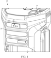
FIG. 1 is a front perspective view of a portion of a portable radio in accordance with one embodiment. -
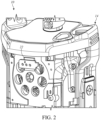
FIG. 2 is a perspective view of the portable radio ofFIG. 1 , with a speaker bezel removed. -
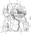
FIG. 3 is a front, right side perspective cross-sectional view of the portable radio ofFIG. 2 . -
FIG. 4 is a right side cross-sectional view of the portable radio ofFIG. 2 . -
FIG. 5 is a front, left side perspective cross-sectional view of the portable radio ofFIG. 2 . -
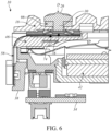
FIG. 6 is a left side cross-sectional view of the portable radio ofFIG. 2 . - Skilled artisans will appreciate that elements in the figures are illustrated for simplicity and clarity and have not necessarily been drawn to scale. For example, the dimensions of some of the elements in the figures may be exaggerated relative to other elements to help to improve understanding of embodiments of the present invention.
- The apparatus and method components have been represented where appropriate by conventional symbols in the drawings, showing only those specific details that are pertinent to understanding the embodiments of the present invention so as not to obscure the disclosure with details that will be readily apparent to those of ordinary skill in the art having the benefit of the description herein.
- Briefly, there is provided herein an improved portable radio. A portable radio, in accordance with one embodiment, includes a button with an outer region that may be pressed by a user during use, a printed circuit board, a frame positioned in front of (exterior to) the printed circuit board, a speaker positioned within the frame, a support platform positioned between the button and the speaker, and electrical components linked between the button and the printed circuit board, such that a signal may be sent from the button to the printed circuit board. A portion of the support platform is positioned over the speaker and includes speaker ports. The button is movable along the first direction between a first position where an electrical signal is sent through the plurality of electrical components to the printed circuit board, and a second position where the electrical signal is interrupted.
-
FIGS. 1-6 illustrate one example of aportable radio 10. As illustrated inFIGS. 1 and2 , theportable radio 10 includes anouter housing 14, for example a rigid outer housing made of plastic. Theouter housing 14 includes aspeaker bezel 18 positioned along a front of theportable radio 10. Theportable radio 10 also includes abutton 22 that is positioned within an opening defined by thespeaker bezel 18. A portion of thebutton 22 is exposed to an environment outside of theportable radio 10 and is visible when thespeaker bezel 18 is attached to the rest of the portable radio 10 (FIG. 1 ). - With reference to
FIGS. 3-6 , thebutton 22 is movable, generally toward an interior of theportable radio 10 and away from the interior. In some embodiments thebutton 22 is biased (for example with a spring) in a direction away from the interior of theportable radio 10. In the illustrated embodiment thebutton 22 includes an outer region 26 (for example generally rectangular in shape) that may be pressed by the user during use. Thebutton 22 further includes an inner region that extends from theouter region 26 and includes a plunger 30 (FIGS. 5 and6 ). Theplunger 30 is a projecting region of thebutton 22 that moves inwardly toward the interior of theportable radio 10 when thebutton 22 is pressed. Thebutton 22 may have other shapes and sizes than that illustrated. - With continued reference to
FIGS. 3-6 , thebutton 22 is electrically coupled to a printedcircuit board 34 within the interior of theportable radio 10. In the illustrated embodiment theportable radio 10 includes aframe 38 positioned in front of (i.e., exterior to) of the printedcircuit board 34. A speaker 42 (FIGS. 5 and6 ) is positioned within theframe 38. Asupport platform 46 is positioned in front of thespeaker 42 and theframe 38. A portion of thesupport platform 46 is positioned over thespeaker 42, and includes speaker ports 50 (FIG. 3 ). As illustrated inFIG. 3 , antenna elements 54 (for example sheet metal antenna elements) may be positioned on regions of thesupport platform 46 adjacent thespeaker ports 50. The antenna elements 54 may be electrically coupled to the printed circuit board 34 (for example through a separate electrical path other than that for the button 22). - With continued reference to
FIGS. 3-6 , theportable radio 10 includes a set of electrical components that are linked between thebutton 22 and theprinted circuit board 34, such that a signal may be sent from thebutton 22 to theprinted circuit board 34. In some embodiments, theportable radio 10 includes at least two, three, four, or in some cases at least five separate electrical components that are separately coupled to one another between thebutton 22 and the printedcircuit board 34. In some embodiments, the electrical components cause the electrical signal to change directions at least two times, three times, or in some cases at least four times as the signal moves through the electrical components between thebutton 22 and the printedcircuit board 34. Thebutton 22 may be movable between a first position where the electrical signal is sent through the electrical components to the printedcircuit board 34, and a second position where the electrical signal is interrupted. - In the illustrated embodiment, the set of electrical components includes an
electrical flex element 58 coupled to thesupport platform 46 and to theframe 38. Theelectrical flex element 58 includes afirst region 62 adhered to thesupport platform 46, and asecond region 66 adhered to theframe 38. Theelectrical flex element 58 further includes a bent region 70 (for example a thin, curved strip) disposed between thefirst region 62 and thesecond region 66. As illustrated inFIGS. 3 and5 , thefirst region 62 extends along a first plane, and thesecond region 66 extends along a second plane that is perpendicular to the first plane. Thebent region 70 is non-planar, and curves from the first plane to the second plane. In the illustrated embodiment the first plane is perpendicular to a direction of movement "D" (FIGS. 4 and6 ) of thebutton 22, and the second plane is parallel to the direction of movement. - With reference to
FIGS. 5 and6 , the set of electrical components further includes atactile dome 74. Thetactile dome 74 is positioned between theplunger 30 of thebutton 22 and theelectrical flex element 58, and may have a dome-like or other shape that provides tactile feedback when pressed and released. When thebutton 22 is in a first position thetactile dome 74 is in a compressed state (is pressed down) and is in contact with theelectrical flex element 58 for example to complete the electrical connection, and when thebutton 22 is in a second position thetactile dome 74 is in an uncompressed state (is raised up) and is out of contact with theelectrical flex element 58 for example to interrupt the electrical connection. In some embodiments, and as illustrated inFIGS. 5 and6 , theportable radio 10 may also include a secondary plunger 78 (for example made of silicone) that is disposed directly behind (interior of) theplunger 30 of thebutton 22, and is positioned between theplunger 30 of thebutton 22 and thetactile dome 74. Thesecondary plunger 78 may form part of a larger silicone structure (or structure made of other soft material) that is coupled to thesupport platform 46. - With reference to
FIGS. 3 and4 , the set of electrical components further includes aspring clip connector 82 that is coupled to thesecond region 66 of theelectrical flex element 58, as well as acontact finger 86 coupled to thespring clip connector 82. Thespring clip connector 82 is disposed between theelectrical flex element 58 and thecontact finger 86. In the illustrated embodiment thecontact finger 86 has a ninety degree bend, although other embodiments include different shapes and sizes than that illustrated. - With continued reference to
FIGS. 3 and4 , the set of electrical components further includes apogo 90 coupled to both thecontact finger 86 and to the printedcircuit board 34. Thepogo 90 extends in an elongate direction that is parallel to the direction of movement D of thebutton 22. Thepogo 90 is disposed within apogo housing 94, and slides within thepogo housing 94. - During use, when the
button 22 is pressed theplunger 30 of thebutton 22 contacts and presses against the soft,secondary plunger 78, which in turn presses against thetactile dome 74. Thetactile dome 74 is compressed, causing thetactile dome 74 to contact thefirst region 62 of theelectrical flex element 58. This contact allows a signal to be sent through theelectrical flex element 58, through thespring clip connector 82, through thecontact finger 86, and through thepogo 90 and into the printedcircuit board 34. The signal thus passes through various different electrical components, and changes direction as is moves generally from thebutton 22 on the exterior of theportable radio 10 to the interior of theportable radio 10 and to the printedcircuit board 34. - In some embodiments, the
portable radio 10 is interactive. For example, thebutton 22 may be a voice control button for establishing voice commands and information exchange with theportable radio 10 when thebutton 22 is pressed, although thebutton 22 may be used for any of a number of different purposes (for example power control, volume control, and the like). In the illustrated embodiment, when thebutton 22 is pressed a voice may emanate from thespeaker 42. For example, the voice may say "Can I help you?" and the user may then ask the portable radio 10 a question (for example asking theportable radio 10 to run a license plate check, or to provide information regarding traffic conditions at a particular location). Theportable radio 10 may then respond with the requested information. - With reference to
FIGS. 3-6 , in the illustrated embodiment thebutton 22 may be exposed to water and other outside environmental conditions, whereas thespeaker 42 may be sealed from water within the frame. For example, thesecondary plunger 78 and/or thetactile dome 74 may be sealed (with adhesive) to thefirst region 62 of the electrical flex element 58 (for example via a perimeter seal), and as described above thefirst region 62 may itself be sealed (with adhesive) to theframe 38 and to thesupport platform 46. As illustrated inFIGS. 3-6 , in some embodiments adebris pad 98 is also coupled to thebutton 22. A portion of thedebris pad 98 is positioned adjacent theplunger 30 of thebutton 22, and a portion of thedebris pad 98 is in contact with an outer surface of thespeaker bezel 18. Additionally, and with reference toFIG. 5 , in the illustrated embodiment theportable radio 10 may include anair vent 102 disposed on thesupport platform 46. Theair vent 102 permits passage of air from behind (interior of) thebutton 22 to an open region disposed behind thesupport platform 46. - In the foregoing specification, specific embodiments have been described. However, one of ordinary skill in the art appreciates that various modifications and changes can be made without departing from the scope of the invention as set forth in the claims below. Accordingly, the specification and figures are to be regarded in an illustrative rather than a restrictive sense, and all such modifications are intended to be included within the scope of present teachings.
- The benefits, advantages, solutions to problems, and any element(s) that may cause any benefit, advantage, or solution to occur or become more pronounced are not to be construed as a critical, required, or essential features or elements of any or all the claims. The invention is defined solely by the appended claims including any amendments made during the pendency of this application and all equivalents of those claims as issued.
- Moreover in this document, relational terms such as first and second, top and bottom, and the like may be used solely to distinguish one entity or action from another entity or action without necessarily requiring or implying any actual such relationship or order between such entities or actions. The terms "comprises," "comprising," "has," "having," "includes," "including," "contains," "containing" or any other variation thereof, are intended to cover a non-exclusive inclusion, such that a process, method, article, or apparatus that comprises, has, includes, contains a list of elements does not include only those elements but may include other elements not expressly listed or inherent to such process, method, article, or apparatus. An element proceeded by "comprises ... a," "has ... a," "includes ... a," or "contains ... a" does not, without more constraints, preclude the existence of additional identical elements in the process, method, article, or apparatus that comprises, has, includes, contains the element. The terms "a" and "an" are defined as one or more unless explicitly stated otherwise herein. The terms "substantially," "essentially," "approximately," "about" or any other version thereof, are defined as being close to as understood by one of ordinary skill in the art, and in one non-limiting embodiment the term is defined to be within 10%, in another embodiment within 5%, in another embodiment within 1% and in another embodiment within 0.5%. The term "coupled" as used herein is defined as connected, although not necessarily directly and not necessarily mechanically. A device or structure that is "configured" in a certain way is configured in at least that way, but may also be configured in ways that are not listed.
- The Abstract of the Disclosure is provided to allow the reader to quickly ascertain the nature of the technical disclosure. It is submitted with the understanding that it will not be used to interpret or limit the scope or meaning of the claims. In addition, in the foregoing Detailed Description, it can be seen that various features are grouped together in various embodiments for the purpose of streamlining the disclosure. This method of disclosure is not to be interpreted as reflecting an intention that the claimed embodiments require more features than are expressly recited in each claim. Rather, as the following claims reflect, inventive subject matter lies in less than all features of a single disclosed embodiment. Thus the following claims are hereby incorporated into the Detailed Description, with each claim standing on its own as a separately claimed subject matter.
Claims (15)
- A portable radio (10) comprising:a button (22) including an outer region (26) that may be pressed by a user during use,a printed circuit board (34);a frame (38) positioned exterior to the printed circuit board (38);a speaker (42) positioned within the frame (38);a support platform (46) positioned between the button (22) and the speaker (42), wherein a portion of the support platform (46) is positioned over the speaker (42) and includes speaker ports (50);
anda plurality of electrical components linked between the button (22) and the printed circuit board (34), such that a signal may be sent from the button (22) to the printed circuit board (34);wherein the button (22) is movable between a first position wherein an electrical signal is configured to be sent through the plurality of electrical components to the printed circuit board, and a second position wherein the electrical signal is configured to be interrupted. - The portable radio (10) of claim 1, wherein the plurality of electrical components includes an electrical flex element (58) coupled to the support platform (46).
- The portable radio (10) of claim 2, wherein the electrical flex element (58) includes a first region (62) adhered to the support platform (46), and a second region (68) adhered to the frame 38).
- The portable radio (10) of claim 3, where the electrical flex element (58) includes a bent region (70) disposed between the first region (62) and the second region (68).
- The portable radio (10) of claim 3, wherein the first region (62) extends along a first plane, and the second region (68) extends along a second plane that is perpendicular to the first plane.
- The portable radio (10) of claim 5, wherein the first plane is perpendicular to a direction of movement of the button (22) between the first position and the second position, and the second plane is parallel to the direction of movement.
- The portable radio (10) of claim 2, wherein the button includes a plunger (30), and wherein the portable radio (10) includes a tactile dome (74) positioned between the plunger (30) and the electrical flex element (50), wherein when the button (22) is in the first position the tactile dome (74) is configured to be in a compressed state, and when the button (22) is in the second position the tactile dome (74) is configured to be in an uncompressed state, wherein preferably the portable radio (10) further comprises a debris pad (98) coupled to the button (22), wherein a portion of the debris pad (98) is positioned adjacent the plunger (30).
- The portable radio (10) of claim 2, wherein the plurality of electrical components further includes a spring clip connector (82) coupled to the electrical flex element (58).
- The portable radio (10) of claim 8, wherein the plurality of electrical components further includes a contact finger (86) coupled to the spring clip connector (82), wherein preferably the contact finger (86) has a ninety degree bend.
- The portable radio (10) of claim 9, wherein the plurality of electrical components further includes a pogo (90) coupled to both the contact finger (86) and to the printed circuit board (34).
- The portable radio (10) of claim 10, wherein the pogo (90) extends in an elongate direction, and wherein the button (22) is configured to move in a direction parallel to the elongate direction between the first position and the second position.
- The portable radio (10) of claim 1, further comprising an air vent (102) disposed on the support platform (46), wherein the air vent (102) is configured to permit passage of air from behind the button (22) to an open region disposed behind the support platform (46).
- The portable radio (10) of claim 1, wherein the plurality of electrical components includes at least five separate components electrically coupled to one another.
- The portable radio (10) of claim 1, wherein the button is configured to be exposed to water, and the speaker is sealed from water within the frame.
- The portable radio (10) of claim 1, wherein the button (22) further includes an inner region that extends from the outer region (26) and includes a plunger (30), the plunger (30) being a region of the button (22) that projects through the support platform (46) and that moves inwardly toward the interior of the portable radio (10) when the button (22) is pressed.
Applications Claiming Priority (2)
| Application Number | Priority Date | Filing Date | Title |
|---|---|---|---|
| US16/370,072 US10779066B1 (en) | 2019-03-29 | 2019-03-29 | Portable radio with button over speaker |
| PCT/US2020/023932 WO2020205283A1 (en) | 2019-03-29 | 2020-03-20 | Portable radio with button over speaker |
Publications (2)
| Publication Number | Publication Date |
|---|---|
| EP3942702A1 EP3942702A1 (en) | 2022-01-26 |
| EP3942702B1 true EP3942702B1 (en) | 2025-04-23 |
Family
ID=70289856
Family Applications (1)
| Application Number | Title | Priority Date | Filing Date |
|---|---|---|---|
| EP20719536.3A Active EP3942702B1 (en) | 2019-03-29 | 2020-03-20 | Portable radio with button over speaker |
Country Status (6)
| Country | Link |
|---|---|
| US (2) | US10779066B1 (en) |
| EP (1) | EP3942702B1 (en) |
| CN (1) | CN113632381B (en) |
| AU (2) | AU2020254409B2 (en) |
| CA (2) | CA3133634C (en) |
| WO (1) | WO2020205283A1 (en) |
Family Cites Families (13)
| Publication number | Priority date | Publication date | Assignee | Title |
|---|---|---|---|---|
| US5265274A (en) | 1990-06-04 | 1993-11-23 | Motorola, Inc. | Combined keypad and speaker porting |
| TW515560U (en) * | 2001-12-06 | 2002-12-21 | Asustek Comp Inc | Pushbutton structure of integrated speaker |
| JP4359812B2 (en) | 2002-07-08 | 2009-11-11 | 日本電気株式会社 | Switch-integrated casing and electronic device having the same |
| TW549555U (en) | 2002-10-25 | 2003-08-21 | High Tech Comp Corp | Button apparatus with a speaker |
| US7274954B2 (en) * | 2004-06-21 | 2007-09-25 | Motorola, Inc. | Communication device including one or more electrical control buttons in an upper housing part |
| US7349551B2 (en) * | 2004-09-03 | 2008-03-25 | Ultra Electronics Audiopack, Inc. | Lapel microphone with push to talk switch |
| US7565178B1 (en) * | 2005-08-16 | 2009-07-21 | Kyocera Wireless Corp. | Portable handset with integrated speaker |
| US7902474B2 (en) | 2008-05-01 | 2011-03-08 | Apple Inc. | Button assembly with inverted dome switch |
| KR101873410B1 (en) * | 2011-11-03 | 2018-08-02 | 엘지전자 주식회사 | Key assembly and mobile terminal having the same |
| KR102058220B1 (en) * | 2013-09-03 | 2019-12-20 | 삼성전자주식회사 | An electroinc device including a key button |
| US9380139B2 (en) | 2013-10-18 | 2016-06-28 | Motorola Solutions, Inc. | Speaker and keypad assembly for a portable communication device |
| US9407978B2 (en) | 2014-11-25 | 2016-08-02 | Motorola Solutions, Inc. | Combined speaker grill and push-to-talk audio accessory |
| KR102573190B1 (en) * | 2015-10-16 | 2023-09-01 | 삼성전자주식회사 | Electronic device and manufacturing method thereof |
-
2019
- 2019-03-29 US US16/370,072 patent/US10779066B1/en active Active
-
2020
- 2020-03-20 EP EP20719536.3A patent/EP3942702B1/en active Active
- 2020-03-20 WO PCT/US2020/023932 patent/WO2020205283A1/en not_active Ceased
- 2020-03-20 CA CA3133634A patent/CA3133634C/en active Active
- 2020-03-20 AU AU2020254409A patent/AU2020254409B2/en active Active
- 2020-03-20 CN CN202080025308.5A patent/CN113632381B/en active Active
- 2020-03-20 CA CA3172144A patent/CA3172144C/en active Active
- 2020-08-05 US US16/985,987 patent/US11197078B2/en active Active
-
2021
- 2021-11-09 AU AU2021266234A patent/AU2021266234B2/en active Active
Also Published As
| Publication number | Publication date |
|---|---|
| US20200314512A1 (en) | 2020-10-01 |
| CN113632381A (en) | 2021-11-09 |
| CA3133634A1 (en) | 2020-10-08 |
| AU2021266234B2 (en) | 2023-01-12 |
| CN113632381B (en) | 2023-05-09 |
| WO2020205283A1 (en) | 2020-10-08 |
| US11197078B2 (en) | 2021-12-07 |
| AU2020254409A1 (en) | 2021-10-28 |
| CA3172144C (en) | 2026-03-03 |
| US10779066B1 (en) | 2020-09-15 |
| EP3942702A1 (en) | 2022-01-26 |
| CA3172144A1 (en) | 2020-10-08 |
| CA3133634C (en) | 2023-04-18 |
| AU2020254409B2 (en) | 2021-12-09 |
| AU2021266234A1 (en) | 2021-12-02 |
| US20200366979A1 (en) | 2020-11-19 |
Similar Documents
| Publication | Publication Date | Title |
|---|---|---|
| EP1507273B1 (en) | Keypad assembly | |
| KR100664365B1 (en) | Push-on switch | |
| US8258418B2 (en) | Keyboard dome overlay structure | |
| EP2360901A1 (en) | Keyboard dome stiffener assembly | |
| TW512374B (en) | Dome-shaped contact plate giving crispy feeling of click and sheet with contact plate | |
| US20080296141A1 (en) | Key Input Apparatus and Electronic Device | |
| CN101908429B (en) | Keystroke fixing structure and portable mobile terminal | |
| CN102376481B (en) | Button structure and electronic device with same | |
| CN102376480B (en) | Key structure and electronic device with same | |
| AU2021266234B2 (en) | Portable radio with button over speaker | |
| JP5722198B2 (en) | Waterproof pushbutton switch member and electronic device including the same | |
| US8586884B2 (en) | Tamper-resistant keypad for mobile device | |
| US7329823B2 (en) | Movable contact element and panel switch formed using the same | |
| KR101388589B1 (en) | Membrane switch module and manufacturing method of the said | |
| JP2006164870A (en) | Movable contact body and panel switch configured using the same | |
| EP2355118B1 (en) | Dome overlay assembly for a keyboard and method of constructing a dome overlay structure for a mobile device keyboard | |
| JP2003234037A (en) | Dome switch | |
| CN201112208Y (en) | push switch | |
| JPH08315674A (en) | Push switch | |
| JP2005077754A (en) | Storage case | |
| KR20050052965A (en) | A keypad apparatus of mobile phone | |
| JP2006172974A (en) | Movable contact body and panel switch configured using the same | |
| JP2013058919A (en) | Portable electronic apparatus and slide key member | |
| JP2005183171A (en) | Sheet with movable contact and push-button switch using same | |
| JP2001043763A (en) | Movable contact and switching device using the movable contact |
Legal Events
| Date | Code | Title | Description |
|---|---|---|---|
| STAA | Information on the status of an ep patent application or granted ep patent |
Free format text: STATUS: UNKNOWN |
|
| STAA | Information on the status of an ep patent application or granted ep patent |
Free format text: STATUS: THE INTERNATIONAL PUBLICATION HAS BEEN MADE |
|
| PUAI | Public reference made under article 153(3) epc to a published international application that has entered the european phase |
Free format text: ORIGINAL CODE: 0009012 |
|
| STAA | Information on the status of an ep patent application or granted ep patent |
Free format text: STATUS: REQUEST FOR EXAMINATION WAS MADE |
|
| 17P | Request for examination filed |
Effective date: 20211022 |
|
| AK | Designated contracting states |
Kind code of ref document: A1 Designated state(s): AL AT BE BG CH CY CZ DE DK EE ES FI FR GB GR HR HU IE IS IT LI LT LU LV MC MK MT NL NO PL PT RO RS SE SI SK SM TR |
|
| STAA | Information on the status of an ep patent application or granted ep patent |
Free format text: STATUS: EXAMINATION IS IN PROGRESS |
|
| 17Q | First examination report despatched |
Effective date: 20220315 |
|
| DAV | Request for validation of the european patent (deleted) | ||
| DAX | Request for extension of the european patent (deleted) | ||
| GRAP | Despatch of communication of intention to grant a patent |
Free format text: ORIGINAL CODE: EPIDOSNIGR1 |
|
| STAA | Information on the status of an ep patent application or granted ep patent |
Free format text: STATUS: GRANT OF PATENT IS INTENDED |
|
| INTG | Intention to grant announced |
Effective date: 20241114 |
|
| GRAS | Grant fee paid |
Free format text: ORIGINAL CODE: EPIDOSNIGR3 |
|
| GRAA | (expected) grant |
Free format text: ORIGINAL CODE: 0009210 |
|
| STAA | Information on the status of an ep patent application or granted ep patent |
Free format text: STATUS: THE PATENT HAS BEEN GRANTED |
|
| P01 | Opt-out of the competence of the unified patent court (upc) registered |
Free format text: CASE NUMBER: APP_7499/2025 Effective date: 20250213 |
|
| AK | Designated contracting states |
Kind code of ref document: B1 Designated state(s): AL AT BE BG CH CY CZ DE DK EE ES FI FR GB GR HR HU IE IS IT LI LT LU LV MC MK MT NL NO PL PT RO RS SE SI SK SM TR |
|
| REG | Reference to a national code |
Ref country code: GB Ref legal event code: FG4D |
|
| REG | Reference to a national code |
Ref country code: CH Ref legal event code: EP |
|
| REG | Reference to a national code |
Ref country code: DE Ref legal event code: R096 Ref document number: 602020049917 Country of ref document: DE |
|
| REG | Reference to a national code |
Ref country code: IE Ref legal event code: FG4D |
|
| REG | Reference to a national code |
Ref country code: NL Ref legal event code: MP Effective date: 20250423 |
|
| PG25 | Lapsed in a contracting state [announced via postgrant information from national office to epo] |
Ref country code: NL Free format text: LAPSE BECAUSE OF FAILURE TO SUBMIT A TRANSLATION OF THE DESCRIPTION OR TO PAY THE FEE WITHIN THE PRESCRIBED TIME-LIMIT Effective date: 20250423 |
|
| REG | Reference to a national code |
Ref country code: AT Ref legal event code: MK05 Ref document number: 1788813 Country of ref document: AT Kind code of ref document: T Effective date: 20250423 |
|
| PG25 | Lapsed in a contracting state [announced via postgrant information from national office to epo] |
Ref country code: FI Free format text: LAPSE BECAUSE OF FAILURE TO SUBMIT A TRANSLATION OF THE DESCRIPTION OR TO PAY THE FEE WITHIN THE PRESCRIBED TIME-LIMIT Effective date: 20250423 Ref country code: ES Free format text: LAPSE BECAUSE OF FAILURE TO SUBMIT A TRANSLATION OF THE DESCRIPTION OR TO PAY THE FEE WITHIN THE PRESCRIBED TIME-LIMIT Effective date: 20250423 Ref country code: PT Free format text: LAPSE BECAUSE OF FAILURE TO SUBMIT A TRANSLATION OF THE DESCRIPTION OR TO PAY THE FEE WITHIN THE PRESCRIBED TIME-LIMIT Effective date: 20250825 |
|
| REG | Reference to a national code |
Ref country code: LT Ref legal event code: MG9D |
|
| PG25 | Lapsed in a contracting state [announced via postgrant information from national office to epo] |
Ref country code: GR Free format text: LAPSE BECAUSE OF FAILURE TO SUBMIT A TRANSLATION OF THE DESCRIPTION OR TO PAY THE FEE WITHIN THE PRESCRIBED TIME-LIMIT Effective date: 20250724 Ref country code: NO Free format text: LAPSE BECAUSE OF FAILURE TO SUBMIT A TRANSLATION OF THE DESCRIPTION OR TO PAY THE FEE WITHIN THE PRESCRIBED TIME-LIMIT Effective date: 20250723 |
|
| PG25 | Lapsed in a contracting state [announced via postgrant information from national office to epo] |
Ref country code: PL Free format text: LAPSE BECAUSE OF FAILURE TO SUBMIT A TRANSLATION OF THE DESCRIPTION OR TO PAY THE FEE WITHIN THE PRESCRIBED TIME-LIMIT Effective date: 20250423 |
|
| PG25 | Lapsed in a contracting state [announced via postgrant information from national office to epo] |
Ref country code: BG Free format text: LAPSE BECAUSE OF FAILURE TO SUBMIT A TRANSLATION OF THE DESCRIPTION OR TO PAY THE FEE WITHIN THE PRESCRIBED TIME-LIMIT Effective date: 20250423 |
|
| PG25 | Lapsed in a contracting state [announced via postgrant information from national office to epo] |
Ref country code: HR Free format text: LAPSE BECAUSE OF FAILURE TO SUBMIT A TRANSLATION OF THE DESCRIPTION OR TO PAY THE FEE WITHIN THE PRESCRIBED TIME-LIMIT Effective date: 20250423 |
|
| PG25 | Lapsed in a contracting state [announced via postgrant information from national office to epo] |
Ref country code: AT Free format text: LAPSE BECAUSE OF FAILURE TO SUBMIT A TRANSLATION OF THE DESCRIPTION OR TO PAY THE FEE WITHIN THE PRESCRIBED TIME-LIMIT Effective date: 20250423 |
|
| PG25 | Lapsed in a contracting state [announced via postgrant information from national office to epo] |
Ref country code: RS Free format text: LAPSE BECAUSE OF FAILURE TO SUBMIT A TRANSLATION OF THE DESCRIPTION OR TO PAY THE FEE WITHIN THE PRESCRIBED TIME-LIMIT Effective date: 20250723 |
|
| PG25 | Lapsed in a contracting state [announced via postgrant information from national office to epo] |
Ref country code: IS Free format text: LAPSE BECAUSE OF FAILURE TO SUBMIT A TRANSLATION OF THE DESCRIPTION OR TO PAY THE FEE WITHIN THE PRESCRIBED TIME-LIMIT Effective date: 20250823 |
|
| PG25 | Lapsed in a contracting state [announced via postgrant information from national office to epo] |
Ref country code: LV Free format text: LAPSE BECAUSE OF FAILURE TO SUBMIT A TRANSLATION OF THE DESCRIPTION OR TO PAY THE FEE WITHIN THE PRESCRIBED TIME-LIMIT Effective date: 20250423 |
|
| PG25 | Lapsed in a contracting state [announced via postgrant information from national office to epo] |
Ref country code: SM Free format text: LAPSE BECAUSE OF FAILURE TO SUBMIT A TRANSLATION OF THE DESCRIPTION OR TO PAY THE FEE WITHIN THE PRESCRIBED TIME-LIMIT Effective date: 20250423 Ref country code: DK Free format text: LAPSE BECAUSE OF FAILURE TO SUBMIT A TRANSLATION OF THE DESCRIPTION OR TO PAY THE FEE WITHIN THE PRESCRIBED TIME-LIMIT Effective date: 20250423 |
|
| PG25 | Lapsed in a contracting state [announced via postgrant information from national office to epo] |
Ref country code: CZ Free format text: LAPSE BECAUSE OF FAILURE TO SUBMIT A TRANSLATION OF THE DESCRIPTION OR TO PAY THE FEE WITHIN THE PRESCRIBED TIME-LIMIT Effective date: 20250423 |
|
| PG25 | Lapsed in a contracting state [announced via postgrant information from national office to epo] |
Ref country code: EE Free format text: LAPSE BECAUSE OF FAILURE TO SUBMIT A TRANSLATION OF THE DESCRIPTION OR TO PAY THE FEE WITHIN THE PRESCRIBED TIME-LIMIT Effective date: 20250423 |
|
| REG | Reference to a national code |
Ref country code: DE Ref legal event code: R097 Ref document number: 602020049917 Country of ref document: DE |
|
| PG25 | Lapsed in a contracting state [announced via postgrant information from national office to epo] |
Ref country code: RO Free format text: LAPSE BECAUSE OF FAILURE TO SUBMIT A TRANSLATION OF THE DESCRIPTION OR TO PAY THE FEE WITHIN THE PRESCRIBED TIME-LIMIT Effective date: 20250423 Ref country code: SK Free format text: LAPSE BECAUSE OF FAILURE TO SUBMIT A TRANSLATION OF THE DESCRIPTION OR TO PAY THE FEE WITHIN THE PRESCRIBED TIME-LIMIT Effective date: 20250423 |
|
| PG25 | Lapsed in a contracting state [announced via postgrant information from national office to epo] |
Ref country code: IT Free format text: LAPSE BECAUSE OF FAILURE TO SUBMIT A TRANSLATION OF THE DESCRIPTION OR TO PAY THE FEE WITHIN THE PRESCRIBED TIME-LIMIT Effective date: 20250423 |
|
| PLBE | No opposition filed within time limit |
Free format text: ORIGINAL CODE: 0009261 |
|
| STAA | Information on the status of an ep patent application or granted ep patent |
Free format text: STATUS: NO OPPOSITION FILED WITHIN TIME LIMIT |
|
| REG | Reference to a national code |
Ref country code: CH Ref legal event code: L10 Free format text: ST27 STATUS EVENT CODE: U-0-0-L10-L00 (AS PROVIDED BY THE NATIONAL OFFICE) Effective date: 20260304 |
|
| 26N | No opposition filed |
Effective date: 20260126 |
|
| PGFP | Annual fee paid to national office [announced via postgrant information from national office to epo] |
Ref country code: GB Payment date: 20260219 Year of fee payment: 7 |
|
| PGFP | Annual fee paid to national office [announced via postgrant information from national office to epo] |
Ref country code: DE Payment date: 20260219 Year of fee payment: 7 |
|
| PGFP | Annual fee paid to national office [announced via postgrant information from national office to epo] |
Ref country code: FR Payment date: 20260219 Year of fee payment: 7 |