EP3942583B1 - Procede de fabrication additive - Google Patents
Procede de fabrication additive Download PDFInfo
- Publication number
- EP3942583B1 EP3942583B1 EP20726211.4A EP20726211A EP3942583B1 EP 3942583 B1 EP3942583 B1 EP 3942583B1 EP 20726211 A EP20726211 A EP 20726211A EP 3942583 B1 EP3942583 B1 EP 3942583B1
- Authority
- EP
- European Patent Office
- Prior art keywords
- crystallisation
- polarisable
- front face
- along
- polarisation
- Prior art date
- Legal status (The legal status is an assumption and is not a legal conclusion. Google has not performed a legal analysis and makes no representation as to the accuracy of the status listed.)
- Active
Links
Images

Classifications
-
- H—ELECTRICITY
- H01—ELECTRIC ELEMENTS
- H01F—MAGNETS; INDUCTANCES; TRANSFORMERS; SELECTION OF MATERIALS FOR THEIR MAGNETIC PROPERTIES
- H01F41/00—Apparatus or processes specially adapted for manufacturing or assembling magnets, inductances or transformers; Apparatus or processes specially adapted for manufacturing materials characterised by their magnetic properties
- H01F41/02—Apparatus or processes specially adapted for manufacturing or assembling magnets, inductances or transformers; Apparatus or processes specially adapted for manufacturing materials characterised by their magnetic properties for manufacturing cores, coils, or magnets
- H01F41/0253—Apparatus or processes specially adapted for manufacturing or assembling magnets, inductances or transformers; Apparatus or processes specially adapted for manufacturing materials characterised by their magnetic properties for manufacturing cores, coils, or magnets for manufacturing permanent magnets
-
- B—PERFORMING OPERATIONS; TRANSPORTING
- B22—CASTING; POWDER METALLURGY
- B22F—WORKING METALLIC POWDER; MANUFACTURE OF ARTICLES FROM METALLIC POWDER; MAKING METALLIC POWDER; APPARATUS OR DEVICES SPECIALLY ADAPTED FOR METALLIC POWDER
- B22F10/00—Additive manufacturing of workpieces or articles from metallic powder
- B22F10/20—Direct sintering or melting
- B22F10/28—Powder bed fusion, e.g. selective laser melting [SLM] or electron beam melting [EBM]
-
- B—PERFORMING OPERATIONS; TRANSPORTING
- B29—WORKING OF PLASTICS; WORKING OF SUBSTANCES IN A PLASTIC STATE IN GENERAL
- B29C—SHAPING OR JOINING OF PLASTICS; SHAPING OF MATERIAL IN A PLASTIC STATE, NOT OTHERWISE PROVIDED FOR; AFTER-TREATMENT OF THE SHAPED PRODUCTS, e.g. REPAIRING
- B29C64/00—Additive manufacturing, i.e. manufacturing of three-dimensional [3D] objects by additive deposition, additive agglomeration or additive layering, e.g. by 3D printing, stereolithography or selective laser sintering
- B29C64/10—Processes of additive manufacturing
- B29C64/141—Processes of additive manufacturing using only solid materials
- B29C64/153—Processes of additive manufacturing using only solid materials using layers of powder being selectively joined, e.g. by selective laser sintering or melting
-
- B—PERFORMING OPERATIONS; TRANSPORTING
- B33—ADDITIVE MANUFACTURING TECHNOLOGY
- B33Y—ADDITIVE MANUFACTURING, i.e. MANUFACTURING OF THREE-DIMENSIONAL [3D] OBJECTS BY ADDITIVE DEPOSITION, ADDITIVE AGGLOMERATION OR ADDITIVE LAYERING, e.g. BY 3D PRINTING, STEREOLITHOGRAPHY OR SELECTIVE LASER SINTERING
- B33Y10/00—Processes of additive manufacturing
-
- B—PERFORMING OPERATIONS; TRANSPORTING
- B33—ADDITIVE MANUFACTURING TECHNOLOGY
- B33Y—ADDITIVE MANUFACTURING, i.e. MANUFACTURING OF THREE-DIMENSIONAL [3D] OBJECTS BY ADDITIVE DEPOSITION, ADDITIVE AGGLOMERATION OR ADDITIVE LAYERING, e.g. BY 3D PRINTING, STEREOLITHOGRAPHY OR SELECTIVE LASER SINTERING
- B33Y80/00—Products made by additive manufacturing
-
- C—CHEMISTRY; METALLURGY
- C30—CRYSTAL GROWTH
- C30B—SINGLE-CRYSTAL GROWTH; UNIDIRECTIONAL SOLIDIFICATION OF EUTECTIC MATERIAL OR UNIDIRECTIONAL DEMIXING OF EUTECTOID MATERIAL; REFINING BY ZONE-MELTING OF MATERIAL; PRODUCTION OF A HOMOGENEOUS POLYCRYSTALLINE MATERIAL WITH DEFINED STRUCTURE; SINGLE CRYSTALS OR HOMOGENEOUS POLYCRYSTALLINE MATERIAL WITH DEFINED STRUCTURE; AFTER-TREATMENT OF SINGLE CRYSTALS OR A HOMOGENEOUS POLYCRYSTALLINE MATERIAL WITH DEFINED STRUCTURE; APPARATUS THEREFOR
- C30B11/00—Single-crystal growth by normal freezing or freezing under temperature gradient, e.g. Bridgman-Stockbarger method
- C30B11/04—Single-crystal growth by normal freezing or freezing under temperature gradient, e.g. Bridgman-Stockbarger method adding crystallising materials or reactants forming it in situ to the melt
- C30B11/08—Single-crystal growth by normal freezing or freezing under temperature gradient, e.g. Bridgman-Stockbarger method adding crystallising materials or reactants forming it in situ to the melt every component of the crystal composition being added during the crystallisation
-
- C—CHEMISTRY; METALLURGY
- C30—CRYSTAL GROWTH
- C30B—SINGLE-CRYSTAL GROWTH; UNIDIRECTIONAL SOLIDIFICATION OF EUTECTIC MATERIAL OR UNIDIRECTIONAL DEMIXING OF EUTECTOID MATERIAL; REFINING BY ZONE-MELTING OF MATERIAL; PRODUCTION OF A HOMOGENEOUS POLYCRYSTALLINE MATERIAL WITH DEFINED STRUCTURE; SINGLE CRYSTALS OR HOMOGENEOUS POLYCRYSTALLINE MATERIAL WITH DEFINED STRUCTURE; AFTER-TREATMENT OF SINGLE CRYSTALS OR A HOMOGENEOUS POLYCRYSTALLINE MATERIAL WITH DEFINED STRUCTURE; APPARATUS THEREFOR
- C30B29/00—Single crystals or homogeneous polycrystalline material with defined structure characterised by the material or by their shape
- C30B29/10—Inorganic compounds or compositions
- C30B29/52—Alloys
-
- B—PERFORMING OPERATIONS; TRANSPORTING
- B22—CASTING; POWDER METALLURGY
- B22F—WORKING METALLIC POWDER; MANUFACTURE OF ARTICLES FROM METALLIC POWDER; MAKING METALLIC POWDER; APPARATUS OR DEVICES SPECIALLY ADAPTED FOR METALLIC POWDER
- B22F2202/00—Treatment under specific physical conditions
- B22F2202/05—Use of magnetic field
-
- B—PERFORMING OPERATIONS; TRANSPORTING
- B22—CASTING; POWDER METALLURGY
- B22F—WORKING METALLIC POWDER; MANUFACTURE OF ARTICLES FROM METALLIC POWDER; MAKING METALLIC POWDER; APPARATUS OR DEVICES SPECIALLY ADAPTED FOR METALLIC POWDER
- B22F2203/00—Controlling
- B22F2203/11—Controlling temperature, temperature profile
-
- B—PERFORMING OPERATIONS; TRANSPORTING
- B22—CASTING; POWDER METALLURGY
- B22F—WORKING METALLIC POWDER; MANUFACTURE OF ARTICLES FROM METALLIC POWDER; MAKING METALLIC POWDER; APPARATUS OR DEVICES SPECIALLY ADAPTED FOR METALLIC POWDER
- B22F2998/00—Supplementary information concerning processes or compositions relating to powder metallurgy
- B22F2998/10—Processes characterised by the sequence of their steps
-
- B—PERFORMING OPERATIONS; TRANSPORTING
- B22—CASTING; POWDER METALLURGY
- B22F—WORKING METALLIC POWDER; MANUFACTURE OF ARTICLES FROM METALLIC POWDER; MAKING METALLIC POWDER; APPARATUS OR DEVICES SPECIALLY ADAPTED FOR METALLIC POWDER
- B22F2999/00—Aspects linked to processes or compositions used in powder metallurgy
-
- B—PERFORMING OPERATIONS; TRANSPORTING
- B29—WORKING OF PLASTICS; WORKING OF SUBSTANCES IN A PLASTIC STATE IN GENERAL
- B29C—SHAPING OR JOINING OF PLASTICS; SHAPING OF MATERIAL IN A PLASTIC STATE, NOT OTHERWISE PROVIDED FOR; AFTER-TREATMENT OF THE SHAPED PRODUCTS, e.g. REPAIRING
- B29C64/00—Additive manufacturing, i.e. manufacturing of three-dimensional [3D] objects by additive deposition, additive agglomeration or additive layering, e.g. by 3D printing, stereolithography or selective laser sintering
- B29C64/20—Apparatus for additive manufacturing; Details thereof or accessories therefor
- B29C64/264—Arrangements for irradiation
- B29C64/268—Arrangements for irradiation using laser beams; using electron beams [EB]
-
- C—CHEMISTRY; METALLURGY
- C22—METALLURGY; FERROUS OR NON-FERROUS ALLOYS; TREATMENT OF ALLOYS OR NON-FERROUS METALS
- C22C—ALLOYS
- C22C2202/00—Physical properties
- C22C2202/02—Magnetic
-
- Y—GENERAL TAGGING OF NEW TECHNOLOGICAL DEVELOPMENTS; GENERAL TAGGING OF CROSS-SECTIONAL TECHNOLOGIES SPANNING OVER SEVERAL SECTIONS OF THE IPC; TECHNICAL SUBJECTS COVERED BY FORMER USPC CROSS-REFERENCE ART COLLECTIONS [XRACs] AND DIGESTS
- Y02—TECHNOLOGIES OR APPLICATIONS FOR MITIGATION OR ADAPTATION AGAINST CLIMATE CHANGE
- Y02P—CLIMATE CHANGE MITIGATION TECHNOLOGIES IN THE PRODUCTION OR PROCESSING OF GOODS
- Y02P10/00—Technologies related to metal processing
- Y02P10/25—Process efficiency
Definitions
- the invention relates to an additive manufacturing process for the formation of polarized parts.
- the present invention relates to an additive manufacturing method for forming magnets.
- Sintered magnets based on rare earths because of their performance, are widely used today. Their manufacture generally involves the shaping of powders, and more particularly the sintering of said powders.
- the part can also be ground.
- the part can also be magnetized under a magnetic field, for example under a magnetic field with an intensity greater than 5 Teslas.
- a magnetic field for example under a magnetic field with an intensity greater than 5 Teslas.
- the direction of the residual magnetization in the magnet is aligned according to the grain alignment direction obtained during step c) and the direction of the residual magnetization (i.e. the direction of the N-S polarization of the magnet depends on the direction of the applied magnetic field).
- Anisotropic magnets generally have the maximum magnetic characteristics, the residual polarization (or residual magnetization) is notably twice that of the same isotropic magnet produced without step c).
- the magnets obtained by such a method known from the state of the art generally have a homogeneous microstructure (on a scale greater than 10 ⁇ m) in terms of composition, porosity, size and shape of the grains. These parameters condition the properties of the magnets, in particular their remanence and their coercivity.
- the magnets are the seat of magnetic losses which cause their heating, and ultimately an alteration of their properties. magnetic.
- it is possible to structure them geometrically, for example in the form of strips.
- this solution due to the fragility of sintered magnets, is difficult to envisage.
- a spatial modulation of the direction of the magnetization of the magnet is sometimes required. Such a result can be obtained by applying a non-uniform magnetic field during the execution of step c).
- a spatial modulation of the direction of the magnetization on a sub-millimeter scale is difficult, if not impossible, to achieve.
- This technique makes it possible in particular to produce structured magnets.
- document [1] cited at the end of the description proposes a process for the additive manufacturing of bonded magnets. More particularly, this method comprises a dilution of magnetic powders in an organic binder. However, this dilution significantly affects the performance of the magnets thus obtained.
- Document [2] cited at the end of the description also proposes a process for the additive manufacturing of magnets.
- this method comprises a condensation on a substrate of powders, made of NdFeB, projected by a laser beam.
- the magnets obtained by this process are isotropic.
- the coercivity of the magnets thus obtained is altered by the presence, within it, of a soft magnetic phase which comprises iron in the cubic phase (so-called “alpha” iron).
- Document [6] cited at the end of the description also proposes a process for manufacturing magnets by melting on a powder bed (for example of NdFeB) by a laser beam, and implementing the application of a magnetic field of 1 tesla to 15 tesla in order to induce a magnetic phase.
- a powder bed for example of NdFeB
- the document WHITE EMMA MARIE HAMILTON ET AL., IEEE TRANSACTIONS ON MAGNETICS, vol. 53, page 2101606; DOI: 10.1109/TMAG.2017.2711965 covers a process for the additive manufacturing of an alnico 8 magnet, where samples are deposited on oriented alnico 9 substrates and heat treated, to form a solid having an isotropic microstructure.
- An object of the present invention is therefore to provide a method for the additive manufacture of magnets that does not require the application of a magnetic field.
- Another object of the present invention is also to propose an additive manufacturing method making it possible to impose on the magnet a spatial modulation of its magnetization on a scale of less than one millimeter.
- Another object of the present invention is also to propose an additive manufacturing process making it possible to give the magnet shapes that are inaccessible by the sintering process known from the state of the art.
- the crystallization seed has a crystallinity adapted to impose on the grains a preferential orientation so that each of the fused layers is polarizable under the effect of a polarization field and that the residual polarization of the layer after polarization by a polarization field is directed in the direction predefined by the seed.
- the crystallization seed according to the present invention makes it possible to choose the crystalline orientation (and in particular of the crystallographic axes) of the grains with respect to the front face of the plate.
- axis of easy polarization is meant a preferred direction along which the polarization is oriented.
- An axis of easy polarization can be a particular crystalline axis.
- polarizable material is meant a material which exhibits a residual polarization (magnetic or electrical) after exposure to an external electromagnetic field.
- the residual polarization is directed along a particular crystallographic axis, called the “easy” polarization axis.
- the method further comprises a step e) of biasing the section, step e) comprising exposing said section to a bias field.
- step b) of merging is carried out by means of a laser, advantageously by means of a laser scanning the exposed surface of the predetermined region.
- the thermal gradient is imposed by the circulation of a heat transfer fluid in one or more circulation ducts provided in the volume of the plate.
- the part comprises a plurality of polarizable sections, advantageously according to different directions.
- the set of crystallization seeds forms a ring, so that at the end of step d), the part forms with its sections a one-piece assembly also in the form of a ring, each sections being polarizable in a direction radial to the ring.
- the crystallization surface has a shape and a crystalline orientation suitable for the formation of a section of cylindrical shape and polarizable along the axis of revolution of said part.
- the crystallization surface has a shape and a crystalline orientation suitable for the formation of a section of cubic shape and polarizable in a direction perpendicular to the front face.
- the at least one crystallization seed is of monocrystalline or oriented polycrystalline form.
- the at least one crystallization seed is chemically different from the polarizable material, advantageously the at least one crystallization seed comprises at least one of the elements chosen from: MgO, Si.
- the at least one crystallization seed and the polarizable material comprise the same material.
- the polarizable material is magnetically polarizable.
- the present invention relates to a process for the additive manufacturing of a part polarized along a direction of polarization.
- polarized part is meant a part having a magnetic residual polarization (for example a magnet) or an electric residual polarization (for example for a ferroelectric material).
- polarizable part or “polarizable section” is meant a part or a section which when subjected to a polarization field, in particular a polarization field in a direction of easy polarization, has a permanent polarization, also called polarization residual.
- the bias field may be a magnetic field such that the residual bias is magnetic residual bias (also called “magnetization").
- the bias field may be an electric field such that the residual bias is an electric bias.
- the residual polarization is, according to the terms of the present invention, oriented along at least one preferred axis, called the “easy polarization direction”.
- the latter is generally a function of the crystallographic orientation of the material forming the part in question.
- direction of easy polarization is meant an axis along which all the dipoles, magnetic or electric, are oriented when they are subjected to a polarization field.
- the crystallization seed has a crystallinity adapted to impose on the grains an orientation so that each of the fused layers is polarizable under the effect of a polarization field.
- a polarization is the consequence of a crystalline order within the part concerned.
- a crystalline order within the meaning of the present invention, can mean a monocrystalline piece or a polycrystalline piece made of grains having a preferential crystallographic orientation.
- a polycrystalline part has a crystalline order if at least 50%, preferably at least 75%, even more preferentially at least 90%, of its grains are preferentially oriented in a particular crystallographic direction.
- the polarization of a part results from a crystalline order of said part.
- the crystallographic direction associated with this crystalline order also defines a direction of easy polarization, and more particularly of easy magnetization.
- FIG. 1 is a schematic representation of a device 10 making it possible to implement the present invention.
- the additive manufacturing device 10 comprises in particular a support 20 mounted on a shaft 30 adapted to ensure a translational movement of the support in a direction XX′ perpendicular to a face of said support.
- a plate 40 comprising a front face 41, is arranged on the support 20.
- the plate may comprise one or more ducts 42 through which a heat transfer fluid intended to regulate the temperature of the plate 40 can circulate.
- At least one crystallization seed 50 is also placed on or in the plate 40.
- the at least one seed comprises a crystallization surface 51 flush with the front face 41 of the plate 40.
- the crystallization seed is in particular a seed having a crystalline order and a crystalline orientation.
- the choice of the crystalline orientation depends on criteria which will be detailed later in the statement.
- the implementation of such a device for the execution of an additive manufacturing process initially comprises the formation of a layer of powder 60 covering the front face 41 (step a)).
- This layer of powder 60 can in particular be formed with a roller 70 (or a squeegee).
- the thickness of the powder layer 60 can be between 10 and 100 ⁇ m.
- the powder layer formation step is followed by a step b) of selective melting of a region 61 of the powder layer 60.
- region 61 is circumscribed by crystallization surface 51.
- the selective fusion can be carried out by means of a laser beam, and in particular by means of a laser beam scanning the surface of the region.
- the method according to the present invention also comprises a step c) of solidification of the region 61 molten during step b).
- This solidification is in particular controlled by imposing a thermal gradient on the molten region 61 during step b).
- the thermal gradient can be imposed by the circulation of a heat transfer fluid in the conduit or conduits 42.
- thermal gradient is imposed in a direction perpendicular to the front face.
- the thermal gradient imposes a direction of propagation of a solidification front of the molten region.
- this solidification front propagates from the front face towards the exposed face of the molten region.
- step b) is implemented with a laser scanning the region, it is also understood that the solidification of step b) can occur in the wake of the laser.
- the combined implementation of the oriented crystallization seed and the thermal gradient makes it possible to impose, during step c) of solidification, a directed solidification and a crystalline order in the region 61.
- region 61 solidified at the end of step c) has a crystalline order and is polarizable along a direction which depends on the crystalline orientation of the crystallization seed.
- the amplitude of the thermal gradient also imposes the speed of propagation and/or the crystallinity of region 61 at the end of step c).
- document [10] cited at the end of the description provides all the information necessary for adjusting the thermal gradient as a function of the degree of crystallinity to be achieved.
- the thermal gradient is adjusted so as to obtain a region, at the end of step c), monocrystalline or polycrystalline with columnar grains perpendicular to the front face.
- the method according to the present invention then comprises a repetition of steps a), b), and c) as many times as necessary so as to obtain a section of a part by stacking fused layers.
- step c) constitutes a seed of crystallization for the execution of a new cycle of steps a), b) , etc).
- step a) can be preceded by a step a1) of preheating the plate, for example to a temperature of between 250°C and 500°C.
- the method may include a step e) of biasing the section, the step comprising exposing said section to a bias field.
- the crystallization seed may have a disc-shaped crystallization surface 2 and a crystalline orientation favoring the formation of a part 2′ of cylindrical shape and whose polarization is perpendicular to the front face.
- the crystallization seed may have a square-shaped crystallization surface 3 and a crystalline orientation favoring the formation of a piece 3′ of cubic shape and whose polarization is perpendicular to the front face.
- the part also comprises a weakly polarized coating layer. This coating layer is obtained in particular by carrying out steps a) and b) of the present invention, and a solidification step during which no thermal gradient is imposed.
- a plurality of seeds 1 can be arranged on the tray.
- each seed may have a crystalline surface 1 in the form of a full arc. All the germs can in particular form a ring.
- the implementation of the additive manufacturing process then makes it possible to form a one-piece magnet 1′ comprising a plurality of magnetized sections each having a polarization along a direction specific to it.
- a one-piece magnet comprising a plurality of sections each having a polarization along a direction specific to it is not limited to a ring shape and can be generalized to any other shape.
- the at least one seed may be chemically different from the part formed.
- the additive manufacturing of magnets comprising SmCo can implement a monocrystalline MgO seed with [110] orientation covered with a buffer layer of 10-20 nm of Cr.
- the buffer layer as described in document [7] cited at the end of the description, makes it possible to control the magnetic properties of the magnet.
- the additive manufacturing of NdFeB magnets can implement a monocrystalline MgO seed with [110] orientation covered with a buffer layer with a thickness of between 10 nm and 20 nm of Cr or of Ta, or a monocrystalline Si seed of [001] orientation covered with a buffer layer of Ta with a thickness of between 80 nm and 100 nm.
- Documents [8] and [9] cited at the end of the description present the advantages relating to these configurations.
- the seed and the magnet can be of the same chemical nature.
- the seed can be either monocrystalline or polycrystalline and present a crystalline order.
- the additive manufacturing process can also include one or more heat treatments intended to homogenize the part, and adjust its microstructure so as to obtain particular magnetic properties.
- the thermal gradient from one cycle of steps a), b) and c) to another can vary so as to locally modify the properties magnetic fields of the magnet, and in particular from one layer to another.
- This adjustment makes it possible to locally modulate the magnetic and thermomechanical properties in order to protect areas of the magnets subjected to demagnetizing fields and/or high mechanical stresses.
- the chemical composition of the powder extended in step a) can vary from one cycle of steps a), b) and c) to another so as to locally modify the magnetic properties of the magnet.
- This adjustment can in particular be carried out in order to increase the coercive field locally, in places subject to stronger demagnetizing fields.
- anisotropic magnets without requiring the use of a magnetic field for the alignment of the grains.
- magnets having a spatial modulation of their magnetization on a scale of less than one millimeter.
Landscapes
- Engineering & Computer Science (AREA)
- Chemical & Material Sciences (AREA)
- Materials Engineering (AREA)
- Manufacturing & Machinery (AREA)
- Physics & Mathematics (AREA)
- Organic Chemistry (AREA)
- Power Engineering (AREA)
- Metallurgy (AREA)
- Crystallography & Structural Chemistry (AREA)
- Optics & Photonics (AREA)
- Inorganic Chemistry (AREA)
- Mechanical Engineering (AREA)
- Plasma & Fusion (AREA)
- Hard Magnetic Materials (AREA)
- Manufacturing Cores, Coils, And Magnets (AREA)
- Powder Metallurgy (AREA)
- Polarising Elements (AREA)
- Treatment Of Steel In Its Molten State (AREA)
- Lubricants (AREA)
Description
- L'invention concerne un procédé de fabrication additive pour la formation de pièces polarisées. En particulier, la présente invention concerne un procédé de fabrication additive pour la formation d'aimants.
- Les aimants frittés à base de terres rares, du fait de leurs performances, sont aujourd'hui abondamment utilisés. Leur fabrication implique généralement la mise en forme de poudres, et plus particulièrement le frittage desdites poudres.
- À cet égard, un procédé de fabrication d'un aimant, qualifié d'anisotrope dans la suite, connu de l'état de la technique, comprend les étapes suivantes :
- a) une étape de synthèse d'un alliage magnétique par fusion et refroidissement rapide, par exemple sur roue (« strip casting » selon la terminologie Anglo-Saxonne), de manière à former des précurseurs solides de la phase magnétique sous forme de rubans ;
- b) une étape de broyage des rubans sous forme d'une poudre, présentant par exemple une granulométrie comprise entre 5 µm et 10 µm, à l'issue de cette étape, la poudre broyée est constituée d'une grande quantité de petits cristaux polarisables appelés grains. Chaque grain est lui-même un réseau périodique d'atomes répartis selon un motif géométrique, appelé maille cristalline. La polarisation est toujours dirigée selon un axe préférentiel de la maille, appelé axe de facile polarisation (ou axe de facile aimantation dans le cas des matériaux magnétiques) et peut être orientée selon les deux sens définis par l'axe de facile polarisation (positif ou négatif). Ainsi, dans un empilement de grains formés par de la poudre broyée, chacun des axes de facile polarisation pointe dans une direction aléatoire, si bien que l'empilement de poudre à un caractère isotrope ;
- c) une étape d'alignement magnétique des poudres sous un champ magnétique, par exemple compris entre 5 Teslas et 8 Teslas, afin d'orienter la direction de facile polarisation de chaque grain selon une direction donnée, de sorte qu'à l'issue de l'étape c) l'empilement de poudre présente un caractère anisotrope ;
- d) une étape de mise en forme par compaction à froid des poudres orientées conservant l'anisotropie de la poudre ;
- e) une étape de frittage, à une température comprise entre 1000°C et 1200 °C afin de densifier la pièce compactée à l'étape d) tout en conservant l'alignement des grains;
- f) une ou plusieurs étapes de recuit à des températures inférieures à la température de frittage pour développer les propriétés magnétiques ;
- À l'issue de l'étape f), la pièce peut également être rectifiée.
- La pièce peut également être aimantée sous champ magnétique, par exemple sous un champ magnétique d'une intensité supérieure à 5 Teslas. En particulier, la direction de l'aimantation résiduelle dans l'aimant est alignée selon la direction d'alignement des grains obtenue lors de l'étape c) et le sens de l'aimantation résiduelle (c'est-à-dire le sens de la polarisation N-S de l'aimant dépend du sens du champ magnétique appliqué).
- Les aimants anisotropes présentent en général les caractéristiques magnétiques maximales, la polarisation résiduelle (ou aimantation résiduelle) est notamment deux fois supérieure à celle du même aimant isotrope produit sans l'étape c).
- Les aimants obtenus par un tel procédé connu de l'état de la technique présentent généralement une micro structure homogène (à une échelle supérieure à 10 µm) en termes de composition, de porosité, de taille et de forme des grains. Ces paramètres conditionnent les propriétés des aimants, notamment leur rémanence et leur coercivité.
- Cependant, ce procédé de frittage pour la mise en forme d'un aimant n'est pas satisfaisant.
- En effet, les aimants sont le siège de pertes magnétiques qui provoquent leur échauffement, et ultimement une altération de leurs propriétés magnétiques. Afin de limiter cet effet, il est possible de les structurer géométriquement, par exemple sous forme de lamelles. Toutefois, cette solution, du fait de la fragilité des aimants frittés, est difficilement envisageable.
- Par ailleurs, une modulation spatiale de la direction de l'aimantation de l'aimant est parfois requise. Un tel résultat peut être obtenu en appliquant un champ magnétique non uniforme lors de l'exécution de l'étape c). Cependant, une modulation spatiale de la direction de l'aimantation sur une échelle inférieure au millimètre est difficile, voire impossible, à réaliser.
- De manière alternative au procédé de frittage connu de l'état de la technique, la fabrication additive semble faire aujourd'hui une percée notable tant dans le domaine du prototypage que celui de la production en série.
- Cette technique permet notamment de réaliser des aimants structurés.
- À cet égard, le document [1] cité à la fin de la description propose un procédé de fabrication additive d'aimants liés. Plus particulièrement, ce procédé comprend une dilution de poudres magnétiques dans un liant organique. Cependant cette dilution affecte de manière notable les performances des aimants ainsi obtenus.
- Le document [2] cité à la fin de la description propose également un procédé de fabrication additive d'aimants. Notamment, ce procédé comprend une condensation sur un substrat de poudres, faites de NdFeB, projetées par un faisceau laser.
- Toutefois, les aimants obtenus par ce procédé sont isotropes.
- Par ailleurs, la coercivité des aimants ainsi obtenus est altérée par la présence, en son sein, d'une phase magnétique douce qui comprend du fer en phase cubique (fer dit « alpha »).
- Les documents [3] à [5] cités à la fin de la description proposent un procédé de fabrication d'aimants par fusion sur lit de poudre (par exemple de NdFeB) par un faisceau laser. Toutefois, aucun de ces documents ne révèle la méthode permettant d'induire une aimantation dans les aimants ainsi formés.
- Le document [6] cité à la fin de la description proposent également un procédé de fabrication d'aimants par fusion sur lit de poudre (par exemple de NdFeB) par un faisceau laser, et mettant en oeuvre l'application d'un champ magnétique de 1 tesla à 15 tesla afin d'induire une phase magnétique.
- De telles valeurs de champ magnétique sont toutefois contraignantes, et ne peuvent être mises en oeuvre facilement dans le cadre de prototypages ou d'une production en grande série.
- Le document DAGMAR GOLL ET AL., PHYSICA STATUS SOLIDI. RAPID RESEARCH LETTERS, vol. 13, page 1800536; DOI: 10.1002/pssr.201800536 couvre un procédé de fabrication additive d'aimant Fe-Nd-B où des couches de poudres sont consolidées localement par fusion par faisceau laser selon une direction de croissance perpendiculaire à l'axe c de la phase Φ.
- Le document WHITE EMMA MARIE HAMILTON ET AL., IEEE TRANSACTIONS ON MAGNETICS, vol. 53, page 2101606; DOI: 10.1109/TMAG.2017.2711965 couvre un procédé de fabrication additive d'un aimant alnico 8, où les échantillons sont déposés sur des substrats orientés d'alnico 9 et traités thermiquement, pour former un solide ayant une microstructure isotrope.
- Un but de la présente invention est donc de proposer un procédé de fabrication additive d'aimants ne nécessitant pas l'application d'un champ magnétique.
- Un autre but de la présente invention est également de proposer un procédé de fabrication additive permettant d'imposer à l'aimant une modulation spatiale de son aimantation sur une échelle inférieure au millimètre.
- Un autre but de la présente invention est également de proposer un procédé de fabrication additive permettant de conférer à l'aimant des formes inaccessibles par le procédé de frittage connu de l'état de la technique.
- Les buts de l'invention sont, au moins en partie, atteints comme définis dans la revendication 1, par un procédé de fabrication additive d'une ou plusieurs sections polarisées d'une pièce à partir d'un ou plusieurs germes de cristallisation présentant une surface de cristallisation en affleurement avec une face avant d'un plateau, le procédé comprenant les étapes suivantes :
- a) la formation d'une couche de poudre d'un matériau polarisable, sur la face avant ;
- b) une fusion sélective d'une région de la couche de poudre circonscrite par la surface de cristallisation ;
- c) l'application d'un gradient thermique selon l'épaisseur de la couche de manière à solidifier la région fondue à l'étape c) ;
- d) une répétition des étapes a), b) et c) de manière à former l'au moins une section par empilage de couches fusionnées, lesdites couches fusionnées étant formées de grains polarisables selon une direction de facile polarisation ;
- Le germe de cristallisation présente une cristallinité adaptée pour imposer aux grains une orientation préférentielle de sorte que chacune des couches fusionnées soit polarisable sous l'effet d'un champ de polarisation et que la polarisation résiduelle de la couche après polarisation par un champ de polarisation soit dirigée dans la direction prédéfinie par le germe.
- Le germe de cristallisation selon la présente invention permet de choisir l'orientation cristalline (et notamment des axe cristallographique) des grains par rapport à la face avant du plateau.
- Il est entendu, sans qu'il soit nécessaire de le préciser que l'orientation préférentielle est celle de la direction de facile polarisation.
- Par « axe de facile polarisation », on entend une direction privilégiée selon laquelle la polarisation s'oriente. Un axe de facile polarisation peut être un axe cristallin particulier.
- Par « matériau polarisable », on entend un matériau qui présente une polarisation résiduelle (magnétique ou électrique) après exposition à un champ électromagnétique externe. La polarisation résiduelle est dirigée selon un axe cristallographique particulier, dit axe de « facile » polarisation.
- Selon un mode de mise en oeuvre, le procédé comprend en outre une étape e) de polarisation de la section, l'étape e) comprenant l'exposition de ladite section à un champ de polarisation.
- Selon un mode de mise en oeuvre, l'étape b) de fusion est exécutée au moyen d'un laser, avantageusement au moyen d'un laser balayant la surface exposée de la région prédéterminée.
- Selon un mode de mise en oeuvre, le gradient thermique est imposé par la circulation d'un fluide caloporteur dans un ou des conduits de circulation ménagés dans le volume du plateau.
- Selon un mode de mise en oeuvre, plusieurs germes de cristallisation sont disposés en affleurement avec la face avant du plateau, et de sorte qu'à l'issue de l'étape d), la pièce comprenne une pluralité de sections polarisables, avantageusement selon des directions différentes.
- Il est ainsi possible de moduler la polarisation la pièce à une échelle supérieure à 10 µm.
- Selon un mode de mise en oeuvre, l'ensemble des germes de cristallisation forme une bague, de sorte qu'à l'issue de l'étape d), la pièce forme avec ses sections un ensemble monobloc également en forme de bague, chacune des sections étant polarisable selon une direction radiale à la bague.
- Selon un mode de mise en oeuvre, la surface de cristallisation présente une forme et une orientation cristalline adaptées pour la formation d'une section de forme cylindrique et polarisable selon l'axe de révolution de ladite pièce.
- Selon un mode de mise en oeuvre, la surface de cristallisation présente une forme et une orientation cristalline adaptées pour la formation d'une section de forme cubique et polarisable selon une direction perpendiculaire à la face avant.
- Selon un mode de mise en oeuvre, l'au moins un germe de cristallisation est de forme monocristalline ou polycristalline orientée.
- Selon un mode de mise en oeuvre, l'au moins un germe de cristallisation est chimiquement différent du matériau polarisable, avantageusement l'au moins un germe de cristallisation comprend au moins un des éléments choisi parmi : MgO, Si.
- Selon un mode de mise en oeuvre, l'au moins un germe de cristallisation et le matériau polarisable comprennent le même matériau.
- Selon un mode de mise en oeuvre, le matériau polarisable est polarisable magnétiquement.
- D'autres caractéristiques et avantages apparaîtront dans la description qui va suivre d'un procédé de fabrication additive selon l'invention, donnés à titre d'exemples non limitatifs, en référence aux dessins annexés dans lesquels :
- La
figure 1 est une représentation schématique selon un plan de coupe d'un dispositif de fabrication additive susceptible d'être mis en oeuvre dans le cadre de la présente invention ; - La
figure 2 est un premier exemple de fabrication d'un aimant par le procédé de fabrication additive selon la présente invention ; - La
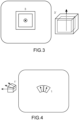
figure 3 est un deuxième exemple de fabrication d'un aimant par le procédé de fabrication additive selon la présente invention ; - La
figure 4 est un troisième exemple de fabrication d'un aimant par le procédé de fabrication additive selon la présente invention ; - La présente invention concerne un procédé de fabrication additive d'une pièce polarisée selon une direction de polarisation.
- Par « pièce polarisée », on entend une pièce présentant une polarisation résiduelle magnétique (par exemple un aimant) ou une polarisation résiduelle électrique (par exemple pour un matériau ferroélectrique).
- Par « pièce polarisable » ou « section polarisable », on entend une pièce ou une section qui lorsqu'elle est soumise à un champ de polarisation, notamment un champ de polarisation selon une direction de facile polarisation, présente une polarisation permanente, également appelée polarisation résiduelle.
- En particulier, le champ de polarisation peut être un champ magnétique de sorte que la polarisation résiduelle soit une polarisation résiduelle magnétique (aussi appelé « aimantation »).
- De manière équivalente, le champ de polarisation peut être un champ électrique de sorte que la polarisation résiduelle soit une polarisation électrique.
- La polarisation résiduelle est, selon les termes de la présente invention, orientée selon au moins un axe privilégié, dit « direction de facile polarisation ». Ce dernier est généralement fonction de l'orientation cristallographique du matériau formant la pièce considérée.
- Par « direction de facile polarisation », on entend un axe selon lequel l'ensemble des dipôles, magnétiques ou électriques, s'orientent dès lors qu'ils sont soumis à un champ de polarisation.
- Le procédé concerne donc la fabrication additive d'une ou plusieurs sections polarisées d'une pièce à partir d'un ou plusieurs germes de cristallisation présentant une surface de cristallisation en affleurement avec une face avant d'un plateau, le procédé comprenant les étapes suivantes :
- a) la formation d'une couche de poudre d'un matériau polarisable, sur la face avant ;
- b) une fusion sélective d'une région de la couche de poudre circonscrite par la surface de cristallisation ;
- c) l'application d'un gradient thermique de manière à générer la propagation d'un front de solidification, à partir de la surface de cristallisation et selon une direction perpendiculaire à la face avant, au sein de de la région fondue, de manière à solidifier cette dernière ;
- d) une répétition des étapes a), b) et c) de manière à former l'au moins une section par empilage de couches fusionnées, lesdites couches fusionnées étant formées de grains polarisables, chacun selon une direction de facile polarisation ;
- Le germe de cristallisation présente une cristallinité adaptée pour imposer aux grains une orientation de sorte que chacune des couches fusionnées soit polarisable sous l'effet d'un champ de polarisation.
- La suite de la description est limitée à un procédé de fabrication additive d'un aimant. Toutefois, l'homme du métier avec ses connaissances générales peut adapter les concepts décris pour la fabrication de pièces présentant une polarisation électrique telles que des pièces ferroélectriques.
- Par ailleurs, il est entendu tout au long de la description qu'une polarisation, qu'elle soit magnétique ou électrique, est la conséquence d'un ordre cristallin au sein de la pièce concernée. En particulier, un ordre cristallin, au sens de la présente invention, peut signifier une pièce monocristalline ou une pièce polycristalline faite de grains présentant une orientation cristallographique préférentielle.
- Sur ce dernier point, tout au long la description, il sera considéré qu'une pièce polycristalline présente un ordre cristallin si au moins 50 %, préférentiellement au moins 75%, encore plus préférentiellement au moins 90%, de ses grains sont préférentiellement orientés selon une direction cristallographique particulière.
- Tel que précisé précédemment, la polarisation d'une pièce résulte d'un ordre cristallin de ladite pièce. Notamment, la direction cristallographique associée à cet ordre cristallin défini également une direction de facile polarisation, et plus particulièrement de facile aimantation.
- La
figure 1 est une représentation schématique d'un dispositif 10 permettant de mettre en oeuvre la présente invention. - Le dispositif de fabrication additive 10 comprend en particulier un support 20 monté sur un arbre 30 adapté pour assurer un mouvement de translation du support selon une direction XX' perpendiculaire à une face dudit support.
- Un plateau 40, comprenant une face avant 41, est disposé sur le support 20. Le plateau peut comprendre un ou plusieurs conduits 42 au travers desquels peut circuler un fluide caloporteur destiné à réguler la température du plateau 40.
- Au moins un germe de cristallisation 50 est également disposé sur ou dans le plateau 40. Notamment, l'au moins un germe comprend une surface de cristallisation 51 en affleurement avec la face avant 41 du plateau 40.
- Le germe de cristallisation est notamment un germe présentant un ordre cristallin et une orientation cristalline. Le choix de l'orientation cristalline est fonction de critères qui seront détaillés dans la suite de l'énoncé.
- La mise en oeuvre d'un tel dispositif pour l'exécution d'un procédé de fabrication additive comprend dans un premier temps la formation d'une couche de poudre 60 en recouvrement de la face avant 41 (étape a)).
- Cette couche de poudre 60 peut en particulier être formée avec un rouleau 70 (ou une raclette).
- L'épaisseur de la couche de poudre 60 peut être comprise entre 10 et 100 µm.
- L'étape de formation de la couche de poudre est suivie d'une étape b) de fusion sélective d'une région 61 de la couche de poudre 60.
- Notamment, la région 61 est circonscrite par la surface de cristallisation 51.
- La fusion sélective peut être exécutée au moyen d'un faisceau laser, et notamment au moyen d'un faisceau laser balayant la surface de la région.
- Le procédé selon la présente invention comprend également une étape c) de solidification de la région 61 fondue lors de l'étape b).
- Cette solidification est notamment contrôlée en imposant un gradient thermique à la région 61 fondue lors de l'étape b). Le gradient thermique peut être imposé par la circulation d'un fluide caloporteur dans le ou les conduits 42.
- Il est entendu, sans qu'il soit nécessaire de le préciser, que le gradient thermique est imposé selon une direction perpendiculaire à la face avant.
- Il est également entendu, sans qu'il soit nécessaire de le préciser, que le gradient thermique impose une direction de propagation d'un front de solidification de la région fondu. Notamment ce front de solidification se propage de la face avant vers la face exposée de la région fondue.
- Dès lors que l'étape b) est mise en oeuvre avec un laser balayant la région, il est également entendu que la solidification de l'étape b) peut se produire dans le sillage du laser.
- La mise en oeuvre combinée du germe de cristallisation orienté et du gradient thermique permet d'imposer, lors de l'étape c) de solidification, une solidification dirigée et un ordre cristallin à la région 61.
- En d'autres termes, la région 61 solidifiée à l'issue de l'étape c) présente un ordre cristallin et est polarisable selon une direction qui est fonction de l'orientation cristalline du germe de cristallisation.
- L'amplitude du gradient thermique impose également la vitesse de propagation et/ou la cristallinité de la région 61 à l'issue de l'étape c). À cet égard, le document [10] cité à la fin de la description fournit toutes les informations nécessaires permettant d'ajuster le gradient thermique en fonction du degré de cristallinité à atteindre.
- En particulier, le gradient thermique est ajusté de manière à obtenir une région, à l'issue de l'étape c), monocristalline ou polycristalline avec des grains colonnaires perpendiculaires à la face avant.
- Le procédé selon la présente invention comprend alors une répétition des étapes a), b), et c) autant de fois que nécessaire de manière à obtenir une section d'une pièce par empilage de couches fusionnées.
- Il est entendu, sans qu'il soit nécessaire de le préciser, que la région solidifiée à l'issue d'une étape c) constitue un germe de cristallisation pour l'exécution d'un nouveau cycle d'étapes a), b), et c).
- De manière complémentaire, l'étape a) peut être précédée d'une étape a1) de préchauffage du plateau, par exemple à une température comprise entre 250°C et 500 °C.
- Enfin, le procédé peut comprendre une étape e) de polarisation de la section, l'étape comprenant l'exposition de ladite section à un champ de polarisation.
- Le procédé décrit ci-avant est donc avantageusement mis en oeuvre pour la fabrication d'aimants. La polarisation (aimantation) de ces derniers résultant de leur ordre cristallin est imposée par le choix et l'orientation cristalline du germe de cristallisation.
- Selon un premier exemple illustré à la
figure 2 , le germe de cristallisation peut présenter une surface de cristallisation en forme de disque 2 et une orientation cristalline favorisant la formation d'une pièce 2' de forme cylindrique et dont la polarisation est perpendiculaire à la face avant. - Selon un second exemple illustré à la
figure 3 , le germe de cristallisation peut présenter une surface de cristallisation en forme carrée 3 et une orientation cristalline favorisant la formation d'une pièce 3' de forme cubique et dont la polarisation est perpendiculaire à la face avant. La pièce comprend en outre couche d'enrobage faiblement polarisée. Cette couche d'enrobage est notamment obtenue par exécution des étapes a) et b) de la présente invention, et une étape de solidification lors de laquelle aucun gradient thermique n'est imposé. - Selon un dernier exemple illustré à la
figure 3 , une pluralité de germes 1 peut être disposée sur le plateau. Notamment chaque germe peut présenter une surface cristalline 1 en forme d'arc plein. L'ensemble des germes peut en particulier former une bague. La mise en oeuvre du procédé de fabrication additive permet alors de former un aimant 1' monobloc et comprenant une pluralité de sections aimantés présentant chacune une polarisation selon une direction qui lui est propre. - La formation d'un aimant monobloc comprenant une pluralité de sections présentant chacune une polarisation selon une direction qui lui est propre n'est pas limitée à une forme de bague et peut être généralisée à toute autre forme.
- Selon une variante de la présente invention, l'au moins un germe peut être chimiquement différent de la pièce formée.
- À titre d'exemple, la fabrication additive d'aimants comprenant du SmCo peut mettre en oeuvre un germe de MgO monocristallin d'orientation [110] recouvert d'une couche buffer de 10-20 nm de Cr. La couche buffer, tel que décrit dans le document [7] cité à la fin de la description, permet de contrôler les propriétés magnétiques de l'aimant.
- Toujours à titre d'exemple, la fabrication additive d'aimants de NdFeB peut mettre en oeuvre un germe de MgO monocristallin d'orientation [110] recouvert d'une couche buffer d'une épaisseur comprise entre 10 nm et 20 nm de Cr ou de Ta, ou un germe de Si monocristallin d'orientation [001] recouvert d'une couche buffer de Ta d'une épaisseur comprise entre 80nm et 100 nm. Les documents [8] et [9] cités à la fin de la description présentent les avantages relatifs à ces configurations.
- Selon une autre variante, le germe et l'aimant peuvent être de même nature chimique. En particulier, le germe peut être au choix monocristallin ou polycristallin et présenter un ordre cristallin.
- Le procédé de fabrication additive peut également comprendre un ou plusieurs traitements thermiques destinés à homogénéiser la pièce, et ajuster sa microstructure de manière à obtenir des propriétés magnétiques particulières.
- De manière complémentaire, le gradient thermique d'un cycle d'étapes a), b) et c) à l'autre peut varier de manière à modifier localement les propriétés magnétiques de l'aimant, et notamment d'une couche à l'autre. Cet ajustement permet de moduler localement les propriétés magnétiques et thermomécaniques afin de protéger des zones des aimants soumises à des champs démagnétisants et/ou des contraintes mécaniques élevées.
- Toujours de manière complémentaire, la composition chimique de la poudre étendue à l'étape a) peut varier d'un cycle d'étapes a), b) et c) à l'autre de manière à modifier localement les propriétés magnétiques de l'aimant.
- Cet ajustement peut notamment être exécuté afin d'augmenter le champ coercitif localement, dans des endroits soumis à des champs démagnétisants plus forts.
- Ainsi, selon la présente invention, il est possible de former par un procédé de fabrication additive des aimants anisotropes sans nécessiter le recours à un champ magnétique pour l'alignement des grains.
- Il est également possible de former des aimants présentant une modulation spatiale de leur aimantation sur une échelle inférieure au millimètre.
-
- [1] : Ling Li et al., « Additive manufacturing of near-net-shape bonded magnets: Prospects and challenges », Scripta Materialia, 135, 100-104, (2017) ;
- [2] : Niyanth Sridharan et al., « Rationalization of solidification mechanism of Nd-Fe-B magnets during laser directed-energy déposition », J. Mater. Sci., 53, 8619-8626, (2018) ;
- [3] : J. Jacimovic et al., « Net Shape 3D Printed NdFeB Permanent Magnet », Advanced Engineering Material, 19(8), (2017) ;
- [4] : Nikolaus Urban et al., « Additive Manifaturing of an Electric Device », International Symposium on Power electronics, Electrical Drives, Automation and Motion, (2018) ;
- [5] :
US 2017/0154713 ; - [6] :
US 2016/0375492 ; - [7] : A.Singh et al., « Pulsed laser deposited epitaxial Sm-Co thin films with uniaxial magnetic texture », Journal of Applied Physics, 99, 08E917, (2006) ;
- [8] : A.R.Kwon et al., « Microstructure and magnetic properties of highly textured Nd-Fe-B films grown on Ta (1 0 0) », Journal of Magnetism and Magntic Materials, 290-291, 1247-1250, (2005) ;
- [9] : Dempsey et al., « High performance hard magnetic NdFeB thick films for intégration into micro-electro-mechanical systems », Applied physics Letters, 90, 09209 (2007) ;
- [10] : W. Kurz et al., « Columnar to equiaxed transition in solidification processing », 2, 185-191, (2001).
Claims (12)
- Procédé de fabrication additive d'une ou plusieurs sections polarisées d'une pièce à partir d'un ou plusieurs germes de cristallisation présentant une surface de cristallisation en affleurement avec une face avant d'un plateau, le procédé comprenant les étapes suivantes :a) la formation d'une couche de poudre d'un matériau polarisable sur la face avant ;b) une fusion sélective d'une région de la couche de poudre circonscrite par la surface de cristallisation ;c) l'application d'un gradient thermique de manière à initier la propagation d'un front de solidification, à partir de la surface de cristallisation et selon une direction perpendiculaire à la face avant, au sein de la région fondue, de manière à solidifier cette dernière ;d) une répétition des étapes a), b) et c) de manière à former l'au moins une section par empilage de couches fusionnées, lesdites couches fusionnées étant formées de grains polarisables selon une direction de facile polarisation ;et dans lequel le ou les germes de cristallisation présentent une cristallinité adaptée pour imposer aux grains une orientation préférentielle de sorte que chacune des couches fusionnées soit polarisable sous l'effet d'un champ de polarisation et que la polarisation résiduelle de la couche après polarisation par un champ de polarisation soit dirigée dans la direction prédéfinie par le ou les germes de cristallisation.
- Procédé selon la revendication 1, dans lequel le procédé comprend en outre une étape e) de polarisation de la section, l'étape e) comprenant l'exposition de ladite section à un champ de polarisation.
- Procédé selon la revendication 1 ou 2, dans lequel l'étape b) de fusion est exécutée au moyen d'un laser, avantageusement au moyen d'un laser balayant la surface exposée de la région prédéterminée.
- Procédé selon l'une des revendications 1 à 3, dans lequel le gradient thermique est imposé par la circulation d'un fluide caloporteur dans un ou des conduits de circulation ménagés dans le volume du plateau.
- Procédé selon l'une des revendications 1 à 4, dans lequel plusieurs germes de cristallisation sont disposés en affleurement avec la face avant du plateau, et de sorte qu'à l'issue de l'étape d), la pièce comprenne une pluralité de sections polarisables, avantageusement selon des directions différentes.
- Procédé selon la revendication 5, dans lequel l'ensemble des germes de cristallisation forme une bague, de sorte qu'à l'issue de l'étape d), la pièce forme avec ses sections un ensemble monobloc également en forme de bague, chacune des sections étant polarisable selon une direction radiale à la bague.
- Procédé selon l'une des revendications 1 à 4, dans lequel la surface de cristallisation présente une forme et une orientation cristalline adaptées pour la formation d'une section de forme cylindrique et polarisable selon l'axe de révolution de ladite pièce.
- Procédé selon l'une des revendications 1 à 4, dans lequel la surface de cristallisation présente une forme et une orientation cristalline adaptées pour la formation d'une section de forme cubique et polarisable selon une direction perpendiculaire à la face avant.
- Procédé selon l'une des revendications 1 à 8, dans lequel l'au moins un germe de cristallisation est de forme monocristalline ou polycristalline orientée.
- Procédé selon l'une des revendications 1 à 9, dans lequel l'au moins un germe de cristallisation est chimiquement différent du matériau polarisable, avantageusement l'au moins un germe de cristallisation est choisi comprenant au moins l'un parmi MgO, Si.
- Procédé selon l'une des revendications 1 à 9, dans lequel l'au moins un germe de cristallisation et le matériau polarisable comprennent le même matériau.
- Procédé selon l'une des revendications 1 à 10, dans lequel le matériau polarisable est polarisable magnétiquement.
Applications Claiming Priority (2)
| Application Number | Priority Date | Filing Date | Title |
|---|---|---|---|
| FR1902977A FR3094133B1 (fr) | 2019-03-22 | 2019-03-22 | Procédé de fabrication additive |
| PCT/FR2020/050557 WO2020193909A1 (fr) | 2019-03-22 | 2020-03-16 | Procede de fabrication additive |
Publications (2)
| Publication Number | Publication Date |
|---|---|
| EP3942583A1 EP3942583A1 (fr) | 2022-01-26 |
| EP3942583B1 true EP3942583B1 (fr) | 2023-04-26 |
Family
ID=67742596
Family Applications (1)
| Application Number | Title | Priority Date | Filing Date |
|---|---|---|---|
| EP20726211.4A Active EP3942583B1 (fr) | 2019-03-22 | 2020-03-16 | Procede de fabrication additive |
Country Status (4)
| Country | Link |
|---|---|
| EP (1) | EP3942583B1 (fr) |
| ES (1) | ES2947175T3 (fr) |
| FR (1) | FR3094133B1 (fr) |
| WO (1) | WO2020193909A1 (fr) |
Family Cites Families (2)
| Publication number | Priority date | Publication date | Assignee | Title |
|---|---|---|---|---|
| EP3180141B1 (fr) | 2014-08-12 | 2018-12-05 | ABB Schweiz AG | Aimant comportant des régions qui présentent différentes propriétés magnétiques, et procédé de formation d'un tel aimant |
| WO2016209823A1 (fr) | 2015-06-24 | 2016-12-29 | Applied Materials, Inc. | Application de champs magnétiques dans l'impression 3d |
-
2019
- 2019-03-22 FR FR1902977A patent/FR3094133B1/fr not_active Expired - Fee Related
-
2020
- 2020-03-16 ES ES20726211T patent/ES2947175T3/es active Active
- 2020-03-16 EP EP20726211.4A patent/EP3942583B1/fr active Active
- 2020-03-16 WO PCT/FR2020/050557 patent/WO2020193909A1/fr not_active Ceased
Also Published As
| Publication number | Publication date |
|---|---|
| ES2947175T3 (es) | 2023-08-02 |
| FR3094133A1 (fr) | 2020-09-25 |
| EP3942583A1 (fr) | 2022-01-26 |
| WO2020193909A1 (fr) | 2020-10-01 |
| FR3094133B1 (fr) | 2021-04-23 |
Similar Documents
| Publication | Publication Date | Title |
|---|---|---|
| US11920224B2 (en) | Additive manufacture of anisotropic rare earth magnets | |
| EP1050056B1 (fr) | Procede de gravure magnetique, pour notamment l'enregistrement magnetique ou magneto-optique | |
| FR3008224A1 (fr) | Aimant fritte annulaire a aimantation radiale, presentant une tenue mecanique renforcee | |
| CA2214482A1 (fr) | Procede de depot d'un film ferromagnetique sur un guide d'onde, et un composant magneto-optique comprenant un film mince ferromagnetique depose selon le procede | |
| FR2895419A1 (fr) | Procede de realisation simplifiee d'une structure epitaxiee | |
| EP3595832B1 (fr) | Matériau métallique fritté à porosité orientée comprenant au moins une partie ferromagnétique et procédé de fabrication | |
| Zhou et al. | Effect of Tb diffusion anisotropy on mechanical and magnetic properties of Nd-Fe-B magnet | |
| EP0076184A1 (fr) | Procédé d'obtention d'une couche à aimantation plane homogène dans un grenat ferrimagnétique | |
| EP3942583A1 (fr) | Procede de fabrication additive | |
| Portavoce et al. | Magnetic moment impact on spin-dependent Seebeck coefficient of ferromagnetic thin films | |
| EP2962337B1 (fr) | Procédé de traitement d'une structure magnétique | |
| Dascalu et al. | Magnetic measurements of RE-Doped cobalt ferrite thin films | |
| Shiratsuchi et al. | Control of the Interfacial Exchange Coupling Energy in Pt/Co/$\alpha $-Cr $ _ {2} $ O $ _ {3} $ Films by Inserting a Pt Spacer Layer at the Co/$\alpha $-Cr $ _ {2} $ O $ _ {3} $ Interface | |
| US8303745B2 (en) | Process for transferring films | |
| Yamaguchi et al. | Nd–Fe–B Thick-Film Magnets on Si Substrates With Al–O Underlayers | |
| WO2024200842A1 (fr) | Procédé de fabrication d'une association de matériaux piézoélectrique et magnétostrictif pour l' obtention d' un matériau composite magnétoélectrique exhibant un comportement auto-polarisé | |
| EP0186531B1 (fr) | Procédé de fabrication d'une couche ayant une forte anisotropie magnétique dans un grenat ferrimagnétique | |
| EP0474566B1 (fr) | Procédé de cristallisation en présence d'un champ magnétique | |
| EP0392907A1 (fr) | Procédé de réalisation d'un dispositif utilisant une structure de films à couches minces | |
| JP2017179396A (ja) | 強磁性合金の製造方法 | |
| FR3116943A1 (fr) | Substrat donneur pour le transfert d’une couche mince et procede de transfert associe | |
| FR2938369A1 (fr) | Procede de fabrication d'une couche d'un materiau antiferromagnetique a structures magnetiques controlees | |
| CN121127112A (zh) | 通过调控Mn3Sn晶面提高非传统自旋轨道力矩效率的制备方法及应用 | |
| 黄致新 et al. | TbCo/Cr amorphous film with perpendicular magneto-anisotropy | |
| WO2011001068A1 (fr) | Procede de modification de la direction d'aimantation d'une couche ferromagnetique |
Legal Events
| Date | Code | Title | Description |
|---|---|---|---|
| STAA | Information on the status of an ep patent application or granted ep patent |
Free format text: STATUS: UNKNOWN |
|
| STAA | Information on the status of an ep patent application or granted ep patent |
Free format text: STATUS: THE INTERNATIONAL PUBLICATION HAS BEEN MADE |
|
| PUAI | Public reference made under article 153(3) epc to a published international application that has entered the european phase |
Free format text: ORIGINAL CODE: 0009012 |
|
| STAA | Information on the status of an ep patent application or granted ep patent |
Free format text: STATUS: REQUEST FOR EXAMINATION WAS MADE |
|
| 17P | Request for examination filed |
Effective date: 20211005 |
|
| AK | Designated contracting states |
Kind code of ref document: A1 Designated state(s): AL AT BE BG CH CY CZ DE DK EE ES FI FR GB GR HR HU IE IS IT LI LT LU LV MC MK MT NL NO PL PT RO RS SE SI SK SM TR |
|
| DAV | Request for validation of the european patent (deleted) | ||
| DAX | Request for extension of the european patent (deleted) | ||
| GRAP | Despatch of communication of intention to grant a patent |
Free format text: ORIGINAL CODE: EPIDOSNIGR1 |
|
| STAA | Information on the status of an ep patent application or granted ep patent |
Free format text: STATUS: GRANT OF PATENT IS INTENDED |
|
| INTG | Intention to grant announced |
Effective date: 20221028 |
|
| GRAS | Grant fee paid |
Free format text: ORIGINAL CODE: EPIDOSNIGR3 |
|
| GRAA | (expected) grant |
Free format text: ORIGINAL CODE: 0009210 |
|
| STAA | Information on the status of an ep patent application or granted ep patent |
Free format text: STATUS: THE PATENT HAS BEEN GRANTED |
|
| AK | Designated contracting states |
Kind code of ref document: B1 Designated state(s): AL AT BE BG CH CY CZ DE DK EE ES FI FR GB GR HR HU IE IS IT LI LT LU LV MC MK MT NL NO PL PT RO RS SE SI SK SM TR |
|
| REG | Reference to a national code |
Ref country code: GB Ref legal event code: FG4D Free format text: NOT ENGLISH |
|
| REG | Reference to a national code |
Ref country code: CH Ref legal event code: EP |
|
| REG | Reference to a national code |
Ref country code: DE Ref legal event code: R096 Ref document number: 602020010146 Country of ref document: DE |
|
| REG | Reference to a national code |
Ref country code: AT Ref legal event code: REF Ref document number: 1563439 Country of ref document: AT Kind code of ref document: T Effective date: 20230515 |
|
| REG | Reference to a national code |
Ref country code: IE Ref legal event code: FG4D Free format text: LANGUAGE OF EP DOCUMENT: FRENCH |
|
| REG | Reference to a national code |
Ref country code: ES Ref legal event code: FG2A Ref document number: 2947175 Country of ref document: ES Kind code of ref document: T3 Effective date: 20230802 |
|
| REG | Reference to a national code |
Ref country code: LT Ref legal event code: MG9D |
|
| REG | Reference to a national code |
Ref country code: NL Ref legal event code: MP Effective date: 20230426 |
|
| REG | Reference to a national code |
Ref country code: AT Ref legal event code: MK05 Ref document number: 1563439 Country of ref document: AT Kind code of ref document: T Effective date: 20230426 |
|
| PG25 | Lapsed in a contracting state [announced via postgrant information from national office to epo] |
Ref country code: NL Free format text: LAPSE BECAUSE OF FAILURE TO SUBMIT A TRANSLATION OF THE DESCRIPTION OR TO PAY THE FEE WITHIN THE PRESCRIBED TIME-LIMIT Effective date: 20230426 |
|
| PG25 | Lapsed in a contracting state [announced via postgrant information from national office to epo] |
Ref country code: SE Free format text: LAPSE BECAUSE OF FAILURE TO SUBMIT A TRANSLATION OF THE DESCRIPTION OR TO PAY THE FEE WITHIN THE PRESCRIBED TIME-LIMIT Effective date: 20230426 Ref country code: PT Free format text: LAPSE BECAUSE OF FAILURE TO SUBMIT A TRANSLATION OF THE DESCRIPTION OR TO PAY THE FEE WITHIN THE PRESCRIBED TIME-LIMIT Effective date: 20230828 Ref country code: NO Free format text: LAPSE BECAUSE OF FAILURE TO SUBMIT A TRANSLATION OF THE DESCRIPTION OR TO PAY THE FEE WITHIN THE PRESCRIBED TIME-LIMIT Effective date: 20230726 Ref country code: AT Free format text: LAPSE BECAUSE OF FAILURE TO SUBMIT A TRANSLATION OF THE DESCRIPTION OR TO PAY THE FEE WITHIN THE PRESCRIBED TIME-LIMIT Effective date: 20230426 |
|
| PG25 | Lapsed in a contracting state [announced via postgrant information from national office to epo] |
Ref country code: RS Free format text: LAPSE BECAUSE OF FAILURE TO SUBMIT A TRANSLATION OF THE DESCRIPTION OR TO PAY THE FEE WITHIN THE PRESCRIBED TIME-LIMIT Effective date: 20230426 Ref country code: PL Free format text: LAPSE BECAUSE OF FAILURE TO SUBMIT A TRANSLATION OF THE DESCRIPTION OR TO PAY THE FEE WITHIN THE PRESCRIBED TIME-LIMIT Effective date: 20230426 Ref country code: LV Free format text: LAPSE BECAUSE OF FAILURE TO SUBMIT A TRANSLATION OF THE DESCRIPTION OR TO PAY THE FEE WITHIN THE PRESCRIBED TIME-LIMIT Effective date: 20230426 Ref country code: LT Free format text: LAPSE BECAUSE OF FAILURE TO SUBMIT A TRANSLATION OF THE DESCRIPTION OR TO PAY THE FEE WITHIN THE PRESCRIBED TIME-LIMIT Effective date: 20230426 Ref country code: IS Free format text: LAPSE BECAUSE OF FAILURE TO SUBMIT A TRANSLATION OF THE DESCRIPTION OR TO PAY THE FEE WITHIN THE PRESCRIBED TIME-LIMIT Effective date: 20230826 Ref country code: HR Free format text: LAPSE BECAUSE OF FAILURE TO SUBMIT A TRANSLATION OF THE DESCRIPTION OR TO PAY THE FEE WITHIN THE PRESCRIBED TIME-LIMIT Effective date: 20230426 Ref country code: GR Free format text: LAPSE BECAUSE OF FAILURE TO SUBMIT A TRANSLATION OF THE DESCRIPTION OR TO PAY THE FEE WITHIN THE PRESCRIBED TIME-LIMIT Effective date: 20230727 |
|
| PG25 | Lapsed in a contracting state [announced via postgrant information from national office to epo] |
Ref country code: FI Free format text: LAPSE BECAUSE OF FAILURE TO SUBMIT A TRANSLATION OF THE DESCRIPTION OR TO PAY THE FEE WITHIN THE PRESCRIBED TIME-LIMIT Effective date: 20230426 |
|
| PG25 | Lapsed in a contracting state [announced via postgrant information from national office to epo] |
Ref country code: SK Free format text: LAPSE BECAUSE OF FAILURE TO SUBMIT A TRANSLATION OF THE DESCRIPTION OR TO PAY THE FEE WITHIN THE PRESCRIBED TIME-LIMIT Effective date: 20230426 |
|
| REG | Reference to a national code |
Ref country code: DE Ref legal event code: R097 Ref document number: 602020010146 Country of ref document: DE |
|
| PG25 | Lapsed in a contracting state [announced via postgrant information from national office to epo] |
Ref country code: SM Free format text: LAPSE BECAUSE OF FAILURE TO SUBMIT A TRANSLATION OF THE DESCRIPTION OR TO PAY THE FEE WITHIN THE PRESCRIBED TIME-LIMIT Effective date: 20230426 Ref country code: SK Free format text: LAPSE BECAUSE OF FAILURE TO SUBMIT A TRANSLATION OF THE DESCRIPTION OR TO PAY THE FEE WITHIN THE PRESCRIBED TIME-LIMIT Effective date: 20230426 Ref country code: RO Free format text: LAPSE BECAUSE OF FAILURE TO SUBMIT A TRANSLATION OF THE DESCRIPTION OR TO PAY THE FEE WITHIN THE PRESCRIBED TIME-LIMIT Effective date: 20230426 Ref country code: EE Free format text: LAPSE BECAUSE OF FAILURE TO SUBMIT A TRANSLATION OF THE DESCRIPTION OR TO PAY THE FEE WITHIN THE PRESCRIBED TIME-LIMIT Effective date: 20230426 Ref country code: DK Free format text: LAPSE BECAUSE OF FAILURE TO SUBMIT A TRANSLATION OF THE DESCRIPTION OR TO PAY THE FEE WITHIN THE PRESCRIBED TIME-LIMIT Effective date: 20230426 Ref country code: CZ Free format text: LAPSE BECAUSE OF FAILURE TO SUBMIT A TRANSLATION OF THE DESCRIPTION OR TO PAY THE FEE WITHIN THE PRESCRIBED TIME-LIMIT Effective date: 20230426 |
|
| PLBE | No opposition filed within time limit |
Free format text: ORIGINAL CODE: 0009261 |
|
| STAA | Information on the status of an ep patent application or granted ep patent |
Free format text: STATUS: NO OPPOSITION FILED WITHIN TIME LIMIT |
|
| 26N | No opposition filed |
Effective date: 20240129 |
|
| PG25 | Lapsed in a contracting state [announced via postgrant information from national office to epo] |
Ref country code: SI Free format text: LAPSE BECAUSE OF FAILURE TO SUBMIT A TRANSLATION OF THE DESCRIPTION OR TO PAY THE FEE WITHIN THE PRESCRIBED TIME-LIMIT Effective date: 20230426 |
|
| PG25 | Lapsed in a contracting state [announced via postgrant information from national office to epo] |
Ref country code: SI Free format text: LAPSE BECAUSE OF FAILURE TO SUBMIT A TRANSLATION OF THE DESCRIPTION OR TO PAY THE FEE WITHIN THE PRESCRIBED TIME-LIMIT Effective date: 20230426 |
|
| REG | Reference to a national code |
Ref country code: CH Ref legal event code: PL |
|
| PG25 | Lapsed in a contracting state [announced via postgrant information from national office to epo] |
Ref country code: BG Free format text: LAPSE BECAUSE OF FAILURE TO SUBMIT A TRANSLATION OF THE DESCRIPTION OR TO PAY THE FEE WITHIN THE PRESCRIBED TIME-LIMIT Effective date: 20230426 |
|
| PG25 | Lapsed in a contracting state [announced via postgrant information from national office to epo] |
Ref country code: LU Free format text: LAPSE BECAUSE OF NON-PAYMENT OF DUE FEES Effective date: 20240316 |
|
| PG25 | Lapsed in a contracting state [announced via postgrant information from national office to epo] |
Ref country code: MC Free format text: LAPSE BECAUSE OF FAILURE TO SUBMIT A TRANSLATION OF THE DESCRIPTION OR TO PAY THE FEE WITHIN THE PRESCRIBED TIME-LIMIT Effective date: 20230426 |
|
| GBPC | Gb: european patent ceased through non-payment of renewal fee |
Effective date: 20240316 |
|
| PG25 | Lapsed in a contracting state [announced via postgrant information from national office to epo] |
Ref country code: MC Free format text: LAPSE BECAUSE OF FAILURE TO SUBMIT A TRANSLATION OF THE DESCRIPTION OR TO PAY THE FEE WITHIN THE PRESCRIBED TIME-LIMIT Effective date: 20230426 Ref country code: LU Free format text: LAPSE BECAUSE OF NON-PAYMENT OF DUE FEES Effective date: 20240316 Ref country code: BG Free format text: LAPSE BECAUSE OF FAILURE TO SUBMIT A TRANSLATION OF THE DESCRIPTION OR TO PAY THE FEE WITHIN THE PRESCRIBED TIME-LIMIT Effective date: 20230426 |
|
| PG25 | Lapsed in a contracting state [announced via postgrant information from national office to epo] |
Ref country code: GB Free format text: LAPSE BECAUSE OF NON-PAYMENT OF DUE FEES Effective date: 20240316 |
|
| PG25 | Lapsed in a contracting state [announced via postgrant information from national office to epo] |
Ref country code: IE Free format text: LAPSE BECAUSE OF NON-PAYMENT OF DUE FEES Effective date: 20240316 |
|
| PG25 | Lapsed in a contracting state [announced via postgrant information from national office to epo] |
Ref country code: IE Free format text: LAPSE BECAUSE OF NON-PAYMENT OF DUE FEES Effective date: 20240316 Ref country code: GB Free format text: LAPSE BECAUSE OF NON-PAYMENT OF DUE FEES Effective date: 20240316 Ref country code: CH Free format text: LAPSE BECAUSE OF NON-PAYMENT OF DUE FEES Effective date: 20240331 |
|
| PGFP | Annual fee paid to national office [announced via postgrant information from national office to epo] |
Ref country code: ES Payment date: 20250416 Year of fee payment: 6 |
|
| PGFP | Annual fee paid to national office [announced via postgrant information from national office to epo] |
Ref country code: IT Payment date: 20250331 Year of fee payment: 6 |
|
| PG25 | Lapsed in a contracting state [announced via postgrant information from national office to epo] |
Ref country code: CY Free format text: LAPSE BECAUSE OF FAILURE TO SUBMIT A TRANSLATION OF THE DESCRIPTION OR TO PAY THE FEE WITHIN THE PRESCRIBED TIME-LIMIT; INVALID AB INITIO Effective date: 20200316 |
|
| PG25 | Lapsed in a contracting state [announced via postgrant information from national office to epo] |
Ref country code: HU Free format text: LAPSE BECAUSE OF FAILURE TO SUBMIT A TRANSLATION OF THE DESCRIPTION OR TO PAY THE FEE WITHIN THE PRESCRIBED TIME-LIMIT; INVALID AB INITIO Effective date: 20200316 |
|
| PG25 | Lapsed in a contracting state [announced via postgrant information from national office to epo] |
Ref country code: TR Free format text: LAPSE BECAUSE OF FAILURE TO SUBMIT A TRANSLATION OF THE DESCRIPTION OR TO PAY THE FEE WITHIN THE PRESCRIBED TIME-LIMIT Effective date: 20230426 |
|
| PGFP | Annual fee paid to national office [announced via postgrant information from national office to epo] |
Ref country code: DE Payment date: 20260320 Year of fee payment: 7 |
|
| PGFP | Annual fee paid to national office [announced via postgrant information from national office to epo] |
Ref country code: BE Payment date: 20260323 Year of fee payment: 7 |
|
| PGFP | Annual fee paid to national office [announced via postgrant information from national office to epo] |
Ref country code: FR Payment date: 20260324 Year of fee payment: 7 |