EP3942412B1 - Adaptive routing pipelines for variable endpoint performance - Google Patents
Adaptive routing pipelines for variable endpoint performance Download PDFInfo
- Publication number
- EP3942412B1 EP3942412B1 EP20718440.9A EP20718440A EP3942412B1 EP 3942412 B1 EP3942412 B1 EP 3942412B1 EP 20718440 A EP20718440 A EP 20718440A EP 3942412 B1 EP3942412 B1 EP 3942412B1
- Authority
- EP
- European Patent Office
- Prior art keywords
- endpoints
- routing
- pipeline
- message
- messages
- Prior art date
- Legal status (The legal status is an assumption and is not a legal conclusion. Google has not performed a legal analysis and makes no representation as to the accuracy of the status listed.)
- Active
Links
Images






Classifications
-
- G—PHYSICS
- G06—COMPUTING OR CALCULATING; COUNTING
- G06F—ELECTRIC DIGITAL DATA PROCESSING
- G06F9/00—Arrangements for program control, e.g. control units
- G06F9/06—Arrangements for program control, e.g. control units using stored programs, i.e. using an internal store of processing equipment to receive or retain programs
- G06F9/46—Multiprogramming arrangements
- G06F9/54—Interprogram communication
- G06F9/546—Message passing systems or structures, e.g. queues
-
- H—ELECTRICITY
- H04—ELECTRIC COMMUNICATION TECHNIQUE
- H04L—TRANSMISSION OF DIGITAL INFORMATION, e.g. TELEGRAPHIC COMMUNICATION
- H04L45/00—Routing or path finding of packets in data switching networks
- H04L45/12—Shortest path evaluation
- H04L45/127—Shortest path evaluation based on intermediate node capabilities
-
- H—ELECTRICITY
- H04—ELECTRIC COMMUNICATION TECHNIQUE
- H04L—TRANSMISSION OF DIGITAL INFORMATION, e.g. TELEGRAPHIC COMMUNICATION
- H04L43/00—Arrangements for monitoring or testing data switching networks
- H04L43/06—Generation of reports
- H04L43/065—Generation of reports related to network devices
-
- H—ELECTRICITY
- H04—ELECTRIC COMMUNICATION TECHNIQUE
- H04L—TRANSMISSION OF DIGITAL INFORMATION, e.g. TELEGRAPHIC COMMUNICATION
- H04L43/00—Arrangements for monitoring or testing data switching networks
- H04L43/08—Monitoring or testing based on specific metrics, e.g. QoS, energy consumption or environmental parameters
- H04L43/0852—Delays
-
- H—ELECTRICITY
- H04—ELECTRIC COMMUNICATION TECHNIQUE
- H04L—TRANSMISSION OF DIGITAL INFORMATION, e.g. TELEGRAPHIC COMMUNICATION
- H04L45/00—Routing or path finding of packets in data switching networks
- H04L45/02—Topology update or discovery
- H04L45/08—Learning-based routing, e.g. using neural networks or artificial intelligence
-
- H—ELECTRICITY
- H04—ELECTRIC COMMUNICATION TECHNIQUE
- H04L—TRANSMISSION OF DIGITAL INFORMATION, e.g. TELEGRAPHIC COMMUNICATION
- H04L45/00—Routing or path finding of packets in data switching networks
- H04L45/12—Shortest path evaluation
- H04L45/121—Shortest path evaluation by minimising delays
-
- H—ELECTRICITY
- H04—ELECTRIC COMMUNICATION TECHNIQUE
- H04L—TRANSMISSION OF DIGITAL INFORMATION, e.g. TELEGRAPHIC COMMUNICATION
- H04L45/00—Routing or path finding of packets in data switching networks
- H04L45/14—Routing performance; Theoretical aspects
-
- H—ELECTRICITY
- H04—ELECTRIC COMMUNICATION TECHNIQUE
- H04L—TRANSMISSION OF DIGITAL INFORMATION, e.g. TELEGRAPHIC COMMUNICATION
- H04L45/00—Routing or path finding of packets in data switching networks
- H04L45/70—Routing based on monitoring results
-
- G—PHYSICS
- G06—COMPUTING OR CALCULATING; COUNTING
- G06F—ELECTRIC DIGITAL DATA PROCESSING
- G06F2209/00—Indexing scheme relating to G06F9/00
- G06F2209/50—Indexing scheme relating to G06F9/50
- G06F2209/508—Monitor
-
- H—ELECTRICITY
- H04—ELECTRIC COMMUNICATION TECHNIQUE
- H04L—TRANSMISSION OF DIGITAL INFORMATION, e.g. TELEGRAPHIC COMMUNICATION
- H04L41/00—Arrangements for maintenance, administration or management of data switching networks, e.g. of packet switching networks
- H04L41/16—Arrangements for maintenance, administration or management of data switching networks, e.g. of packet switching networks using machine learning or artificial intelligence
-
- H—ELECTRICITY
- H04—ELECTRIC COMMUNICATION TECHNIQUE
- H04L—TRANSMISSION OF DIGITAL INFORMATION, e.g. TELEGRAPHIC COMMUNICATION
- H04L41/00—Arrangements for maintenance, administration or management of data switching networks, e.g. of packet switching networks
- H04L41/50—Network service management, e.g. ensuring proper service fulfilment according to agreements
- H04L41/5003—Managing SLA; Interaction between SLA and QoS
- H04L41/5009—Determining service level performance parameters or violations of service level contracts, e.g. violations of agreed response time or mean time between failures [MTBF]
-
- H—ELECTRICITY
- H04—ELECTRIC COMMUNICATION TECHNIQUE
- H04L—TRANSMISSION OF DIGITAL INFORMATION, e.g. TELEGRAPHIC COMMUNICATION
- H04L41/00—Arrangements for maintenance, administration or management of data switching networks, e.g. of packet switching networks
- H04L41/50—Network service management, e.g. ensuring proper service fulfilment according to agreements
- H04L41/5003—Managing SLA; Interaction between SLA and QoS
- H04L41/5019—Ensuring fulfilment of SLA
- H04L41/5025—Ensuring fulfilment of SLA by proactively reacting to service quality change, e.g. by reconfiguration after service quality degradation or upgrade
Definitions
- Routing provides routing of messages to specified service-facing endpoints. The routing is based on rules that are evaluated for every message, which may result in some messages being routed to multiple endpoints. Routing may be accompanied by pre-processing to enrich messages by adding extra data from other sources and transforming messages to a difference schema if necessary.
- Systems are needed to provide improved publish-to-delivery latency for messages delivered to one or more of multiple endpoints. Such systems may reduce the effect of a slow or failed endpoint on the delivery of messages to other endpoints without consuming an unsuitable amount of available computing resources.
- US2017/0163495A1 describes techniques for using a message spinning engine to create and/or manage messaging queues in a distributed network using virtual servers.
- An abstraction layer formed by virtualized servers may enable the message spinning engine to seamlessly transition messaging queues while minimizing the likelihood of exceeding the parameters of existing service level agreements.
- the message spinning engine may include a service mapping module to maintain mappings between source business applications and virtualized servers, a product bridge to implement message encapsulation for communication between different messaging queue products, and a messaging queue monitoring console to analyze performance and capacity of physical services and messaging services and accordingly adjust levels of service for source business applications.
- Embodiments address the foregoing by dynamically adding and removing routing pipelines based on endpoint performance.
- Embodiments create a separate routing pipeline for each of one or more classes of low-performing endpoints and assign endpoints to the various routing pipelines based on monitored endpoint performance.
- An endpoint may be re-assigned from one pipeline to another if the performance of the endpoint changes.
- Embodiments therefore contain the effect of slow endpoints to one or more routing pipelines while well-performing endpoints are served by a dedicated routing pipeline.
- a limited and configurable number of overall routing pipelines ensures efficient resource consumption.
- Examples may employ any suitable system to measure endpoint performance.
- the generation of pipelines and assignment of endpoints to pipelines are based on predictions of future endpoint performance, which may in turn be based on current and historical endpoint performance.
- some examples measure endpoint performance by tracking an exponential moving average of the time taken to write a message to the endpoint. If writing a message to an endpoint is asynchronous (e.g., through a buffer or any other async mechanism), endpoint performance may be measured by tracking an exponential moving average the latency of initiating the call (i.e., buffer wait time).
- Some examples further provide a catch-up routing pipeline.
- the catch-up routing pipeline allows an endpoint to catch-up to the message checkpoint position of its new higher-performance pipeline before joining the higher-performance pipeline.
- the catch-up pipeline also enables the system to confirm the improved performance of the endpoint before assigning the endpoint to the higher-performance pipeline. Operation of the catch-up routing pipeline will be described below.
- routing service customers may be offered endpoint prioritization (i.e., fixed assignment to a default routing pipeline) and/or endpoint grouping (i.e., fixed assignment of one or more endpoints to a particular pipeline), perhaps for appropriate additional fees.
- endpoint prioritization i.e., fixed assignment to a default routing pipeline
- endpoint grouping i.e., fixed assignment of one or more endpoints to a particular pipeline
- a customer may be provided with the ability to manually upgrade to downgrade endpoints to particular routing pipelines based on contextual information such as an endpoint maintenance window and known downstream problems.
- FIG. 1 is a block diagram of system 100 to describe an example of a generic example.
- System 100 includes routing component 110, incoming messages 120, 122 and 124, and endpoints 130, 132 and 134.
- routing component 110 receives messages 120, 122 and 124 and routes each message to an appropriate one of endpoints 130, 132 and 134.
- Messages 120, 122 and 124 may comprise any type of messages conforming to any type of protocol and containing any type of payload that is or becomes known. Messages 120, 122 and 124 may also be received from any one or more message sources that are or become known. Similarly, endpoints 130, 132 and 134 may comprise any type of computing message endpoints that are or become known.
- Routing component 110 includes routing pipelines 112 and 114, although examples are not limited to two routing pipelines. Each of routing pipelines 112 and 114 is assigned to deliver messages to one or more of endpoints 130, 132 and 134. The assignment is based on the relative performance of each endpoint. As shown, routing pipeline 112 delivers messages to endpoints 130 and 132, whose performance is determined to be above a threshold, and pipeline 114 delivers messages to endpoint 134, whose performance is determined to be below the threshold.
- each of routing pipelines 112 and 114 receives each of messages 120, 122 and 124, reads and pre-processes each of messages 120, 122 and 124, and delivers appropriate ones of messages 120, 122 and 124 to its assigned endpoint(s). For example, it will be assumed that message 120 is to be delivered to all endpoints, message 122 is to be delivered to endpoint 130, and message 124 is to be delivered to all endpoint 134. Accordingly, routing pipeline 112 delivers message 120 to endpoints 130 and 132 and delivers message 122 to endpoint 130, and routing pipeline 114 delivers message 120 and message 124 to endpoint 134.
- Routing component 110, endpoints 130, 132 and 134, and each other component described herein may be implemented by one or more computing devices (e.g., computer servers), storage devices (e.g., hard or solid-state disk drives), and other hardware as is known in the art.
- the components may be located remote from one another and may be elements of one or more cloud computing platforms, including but not limited to a Software-as-a-Service, a Platform-as-a-Service, and an Infrastructure-as-a-Service platform.
- each routing pipeline 112 and 114 is implemented by a dedicated virtual machine.
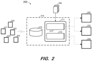
- FIG. 2 is a block diagram of a more detailed example according to some examples.
- System 200 includes hub 210, IoT devices 220-224, and endpoints 230, 232 and 234.
- Hub 210 receives messages from IoT devices 220-224 and routes appropriate ones of messages to one or more of endpoints 230, 232 and 234. Implementations may include a large number (e.g., hundreds, thousands or more) of IoT devices.
- Endpoints 230, 232 and 234 may comprise an external event hub, external storage, a distributed database, etc.
- Hub 210 includes gateway 215 to receive messages from IoT devices 220-224 and routing service 211 to route the received messages.
- Routing service 211 uses routing policy to determine the endpoint(s) to which a particular message should be delivered. According to routing policy 240, the determination may be based on message source, message type, message content and/or any other factors that are or become known. Some messages received from IoT devices 220-224 may be consumed at an event hub of hub 210 and not delivered to external endpoints.
- Each of routing pipelines 212 and 214 applies routing policy 240 to each message received at gateway 215 and, if routing policy 240 indicates that a received message should be delivered to one or more endpoints assigned to the pipeline, the pipeline delivers the message to the one or more endpoints. Routing pipelines 212 and 214 may therefore ignore routing policies which are not relevant to any of their assigned endpoints.
- endpoint 234 has been identified as being slow to process incoming messages.
- endpoint 234 is not currently processing messages slowly but is predicted to be slow in the near future. Techniques for measuring and predicting endpoint performance will be described below.
- Endpoint 234 is therefore assigned to "slow" routing pipeline 214, while better-performing endpoints 230 and 234 are assigned to "default" routing pipeline 212. Accordingly, routing pipeline 212 delivers messages to endpoints 230 and 232, and pipeline 214 delivers messages to endpoint 234. Consequently, the slow performance of endpoint 234 does not negatively affect the delivery of messages to endpoints 230 and 232.
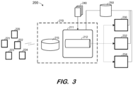
- FIG. 3 also illustrates checkpoint store 250, in communication with routing service 211 and each of endpoints 230, 232 and 234.
- Each routing pipeline maintains a checkpoint of its last successfully-delivered message. In case of a power failure, the routing pipeline only has to resend those messages which were processed after the checkpoint. A routing pipeline moves its checkpoint forward only after a message has been processed by each endpoint for which it is intended.
- Each endpoint also keeps a checkpoint of the last message it successfully processed.
- each endpoint may include a message buffer to store received but not-yet-processed messages.
- FIG. 4 is a flow diagram of process 400 to re-assign endpoints to routing pipelines based on endpoint performance according to some examples.
- Process 400 and the other processes described herein may be performed using any suitable combination of hardware or software. Executable code embodying these processes may be executed by a central processing unit of a microprocessor or microcontroller, for example, and may be stored in any non-transitory tangible medium, including a read-only memory, a volatile or non-volatile random access memory, a fixed disk, a DVD, a Flash drive, or a magnetic tape. Examples are not limited to the examples described below.
- system 200 is operating prior to S410 to receive messages from IoT devices 220-224 and deliver them to appropriate ones of endpoints 230, 232 and 234. As described above, such delivery results in updating of checkpoints respectively associated with routing pipeline 212, endpoint 230, endpoint 232 and endpoint 234.
- Process 400 pauses at S410 for a preconfigured interval before continuing to S420.
- the interval is specified to prevent continuous evaluation and re-assigning of endpoints among routing pipelines.
- process 400 starts with an initial delay to capture a first x minutes of endpoint performance information and then repeats every 30 seconds.
- each existing endpoint is evaluated to determine whether the endpoint is unhealthy or slow.
- Endpoint performance may be determined based on many different metrics such as write/publish latency, failure rate, etc.
- each endpoint may be associated with a small in-memory buffer to absorb endpoint performance fluctuations. Some examples may monitor, for each endpoint, a duration during which the buffer is full. This duration (i.e., "buffer wait time") corresponds to a duration over which a routing pipeline assigned to the endpoint is blocked because no more messages can be enqueued in the endpoint's buffer.
- the determination at S420 may be performed using a prediction model which is based on the buffer wait time. For example, an exponential moving average may be determined for each endpoint at S420.
- EMA next ⁇ ⁇ EMA t + (1- ⁇ ) ⁇ EMA t-1 .
- a prediction model may comprise a Markov decision process, or a machine learning neural network which is trained based on historical endpoint performance data and inputs which may include, but are not limited to, time, customer configuration, region of customer, and endpoint type.
- the determination at S420 may consist of determining whether the performance metric (e.g., the predicted buffer wait time) reflects significantly worse performance than other endpoints assigned to the same routing pipeline. For example, in the case of FIG. 3 , it is determined whether the performance of any one of endpoints 230, 232 and 234 is significantly worse than the performance of the other two endpoints. In this regard, endpoint slowness is measured relative to the slowness of all other endpoints sharing a same routing pipeline.
- the performance metric e.g., the predicted buffer wait time
- an endpoint is considered slow if its performance is more than 10x worse than the best-performing endpoint of its same routing pipeline.
- pipeline assignment may be based on a linear scale (e.g., endpoints exhibiting 1 to n times worse latency of best-performing endpoint assigned to a default pipeline, n to In assigned to a slow pipeline, all others assigned to a stuck pipeline).
- pipeline assignment may be based on an exponential scale (e.g., endpoints exhibiting 1 to n times worse latency of best-performing endpoint assigned to a default pipeline, n to n 2 assigned to a slow pipeline, all others assigned to a stuck pipeline). Flow returns to S410 to wait if none of endpoints 230, 232 and 234 are determined to be slow at S420.
- each endpoint is also associated with an Unhealthy Since timestamp (e.g., stored in checkpoint store 250).
- the timestamp is updated each time a message is successfully received. Accordingly, if an endpoint has been unable to accept messages for a long time, a large difference will exist between its Unhealthy Since timestamp and the current time.
- S420 may also include a determination of whether an endpoint is unhealthy based on its Unhealthy Since timestamp.
- endpoint 234 is determined to be slow at S420. Flow therefore proceeds to S430 to determine whether routing service 211 includes a routing pipeline associated with lower-performance endpoints. With respect to the FIG. 3 example, the determination at S430 is negative and flow therefore proceeds to S440.
- a new routing pipeline is instantiated at S440.
- the new routing pipeline is intended to deliver incoming messages to a lower-performing group of one or more endpoints.
- S440 includes halting and restarting routing service 211 with a new configuration including an additional pipeline such as pipeline 214 of FIG. 5 .
- new routing pipeline 214 is assigned to endpoint 234 at S450 and routing pipeline 212 remains assigned to endpoints 230 and 232.
- the checkpoint values of pipeline 212 and endpoints 230 and 232 remain as they were prior to the restart.
- New pipeline 214 is assigned the checkpoint of the routing pipeline (i.e., routing pipeline 212) from which endpoint 234 was re-assigned.
- S420 is performed for each endpoint of each routing pipeline and as described above, the performance of an endpoint is evaluated only against the performance of other endpoints in its pipeline. Accordingly, if two endpoints are assigned to routing pipeline 214 and the performance of one of the endpoints is significantly worse than the other, a third pipeline may be instantiated at S440 and the worse-performing endpoint may be assigned thereto at S450. Additional pipelines may be added for increasingly poor-performing endpoints. In another example, if it is determined that the performance of endpoint 230 is significantly worse that the performance of endpoint 232, endpoint 230 may be re-assigned to pipeline 214 at S450.
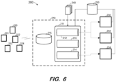
- instantiation of a second routing pipeline at S440 includes instantiation of a third "catch-up" pipeline such as pipeline 216 of FIG. 6 .
- a third "catch-up" pipeline such as pipeline 216 of FIG. 6 .
- an endpoint is re-assigned to catch-up pipeline 216 if a sufficient improvement in its performance is detected. Only one endpoint is assigned to the catch-up pipeline at any given time.
- Catch-up pipeline 216 is used to confirm that an endpoint has actually recovered so it isn't quickly re-assigned back to a lower-performance pipeline after being assigned to the default pipeline.
- Catch-up pipeline 216 also allows the recovered endpoint to catch up with the message queue before being re-assigned to the default pipeline.
- the periodic determination at S420 may include evaluation of whether the performance of the endpoint associated with the catch-up routing pipeline has improved to a sufficient degree. The determination may be based on any of the above-mentioned performance measures. Moreover, the performance of the endpoint may be compared to the performance of the endpoints of the default routing pipeline to determine whether the performance has improved to a sufficient degree (e.g., better than 10x worse than the best-performing endpoint of the default routing pipeline).
- FIG. 7 illustrates reassignment of endpoint 234 from "slow" routing pipeline 214 to catch-up pipeline 216 after a determination that the performance of endpoint 234 has sufficiently improved. Reassignment includes updating the checkpoint of routing pipeline 214 to equal the current checkpoint of endpoint 234.
- FIG. 8 is a flow diagram of a process to re-assign an endpoint from a catch-up routing pipeline to a default routing pipeline according to some examples.
- Process 800 may be performed with respect to a catch-up routing pipeline and not for any of the other pipelines of routing service 211.
- an audit interval at S810 (which may be equal to or different from the other audit intervals discussed herein)
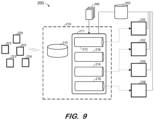
- FIG. 9 illustrates system 200 including four routing pipelines.
- the example shows default pipeline 212, slow pipeline 214, catch-up pipeline 216 and "stuck" pipeline 218.
- Stuck pipeline 218 is assigned to endpoint 238.
- stuck pipeline 218 is assigned to endpoints which have been unhealthy (e.g., as indicated by their Unhealthy Since parameter) for at least a given amount of time (e.g., one hour). An endpoint may move from stuck pipeline 218 to catch-up pipeline 216 if a performance improvement is detected, just as an endpoint may be moved from slow pipeline 214 to catch-up pipeline 216.
- pipeline 218 is a "slower" pipeline which is assigned to endpoints whose performance is at least 10x worse than the performance of the best-performing endpoint assigned to slow endpoint 214.
- FIG. 10 is a block diagram of system 1000 according to some examples.
- System 1000 may comprise a general-purpose computing server and may execute program code to provide a routing service as described herein.
- System 1000 may be implemented by a cloud-based virtual server according to some examples.
- System 1000 includes processing unit 1010 operatively coupled to communication device 1020, persistent data storage system 1030, one or more input devices 1040, one or more output devices 1050 and volatile memory 1060.
- Processing unit 1010 may comprise one or more processors, processing cores, etc. for executing program code.
- Communication interface 1020 may facilitate communication with external devices, such as client devices, and data providers as described herein.
- Input device(s) 1040 may comprise, for example, a keyboard, a keypad, a mouse or other pointing device, a microphone, a touch screen, and/or an eye-tracking device.
- Output device(s) 1050 may comprise, for example, a display (e.g., a display screen), a speaker, and/or a printer.
- Data storage system 1030 may comprise any number of appropriate persistent storage devices, including combinations of magnetic storage devices (e.g., magnetic tape, hard disk drives and flash memory), optical storage devices, Read Only Memory (ROM) devices, etc.
- Memory 1060 may comprise Random Access Memory (RAM), Storage Class Memory (SCM) or any other fast-access memory.
- Routing service 1032 may comprise program code executed by processing unit 1010 to cause system 1000 to instantiate and manage routing pipelines which receive, pre-process, and deliver messages as described herein. Routing policies 1035 may determine how and where messages are routed, checkpoints 1036 may include current checkpoints of routing pipelines and endpoints, and performance information 1037 may include data indicating the current and/or predicted performance of the endpoints as described herein. Data storage device 1030 may also store data and other program code for providing additional functionality and/or which are necessary for operation of system 1000, such as device drivers, operating system files, etc.
- each component or device described herein may be implemented by any number of devices in communication via any number of other public and/or private networks. Two or more of such computing devices may be located remote from one another and may communicate with one another via any known manner of network(s) and/or a dedicated connection. Each component or device may comprise any number of hardware and/or software elements suitable to provide the functions described herein as well as any other functions.
Landscapes
- Engineering & Computer Science (AREA)
- Computer Networks & Wireless Communication (AREA)
- Signal Processing (AREA)
- Theoretical Computer Science (AREA)
- Software Systems (AREA)
- Artificial Intelligence (AREA)
- Environmental & Geological Engineering (AREA)
- Evolutionary Computation (AREA)
- Medical Informatics (AREA)
- General Engineering & Computer Science (AREA)
- General Physics & Mathematics (AREA)
- Physics & Mathematics (AREA)
- Data Exchanges In Wide-Area Networks (AREA)
Description
- Conventional message routing services provide routing of messages to specified service-facing endpoints. The routing is based on rules that are evaluated for every message, which may result in some messages being routed to multiple endpoints. Routing may be accompanied by pre-processing to enrich messages by adding extra data from other sources and transforming messages to a difference schema if necessary.
- Messages to all endpoints are published at the same rate, so the slowest endpoint determines the overall rate of message publishing and the complete pipeline halts if any one endpoint is unresponsive. The latter scenario may be addressed by ignoring endpoints which have been unresponsive for a specified period of time (e.g., one hour), but such an approach does not address the problems caused by slow-but-functioning endpoints.
- One option to improve overall latency is to create a separate pipeline per endpoint. This option would prevent one endpoint from hindering the transmission of messages to another endpoint. However, since each pipeline reads and pre-processes all received messages, each additional pipeline requires duplicative reading and pre-processing resources. Each additional pipeline also requires additional bookkeeping overhead to avoid sending duplicate messages.
- Systems are needed to provide improved publish-to-delivery latency for messages delivered to one or more of multiple endpoints. Such systems may reduce the effect of a slow or failed endpoint on the delivery of messages to other endpoints without consuming an unsuitable amount of available computing resources.
-
US2017/0163495A1 describes techniques for using a message spinning engine to create and/or manage messaging queues in a distributed network using virtual servers. An abstraction layer formed by virtualized servers may enable the message spinning engine to seamlessly transition messaging queues while minimizing the likelihood of exceeding the parameters of existing service level agreements. The message spinning engine may include a service mapping module to maintain mappings between source business applications and virtualized servers, a product bridge to implement message encapsulation for communication between different messaging queue products, and a messaging queue monitoring console to analyze performance and capacity of physical services and messaging services and accordingly adjust levels of service for source business applications. - The invention relates to a system and a method as set forth in the appended claims. It will be understood that aspects of this disclosure falling outside the scope of the claims may not be part of the invention but may be useful to understand the invention.
- The invention is set out in the appended set of claims.
-
-
FIG. 1 is a diagram of a message routing architecture including multiple routing pipelines according to some examples. -
FIG. 2 is a diagram of an Internet of Things (IoT) message routing architecture including multiple routing pipelines according to some examples. -
FIG. 3 is a diagram of an IoT message routing architecture according to some examples. -
FIG. 4 is a flow diagram of a process to adaptively employ multiple routing pipelines based on endpoint performance according to some examples. -
FIG. 5 is a diagram of theFIG. 3 IoT message routing architecture after instantiation of a slow performance routing pipeline according to some examples. -
FIG. 6 is a diagram of theFIG. 3 IoT message routing architecture after instantiation of a slow performance routing pipeline and a catch-up routing pipeline according to some examples. -
FIG. 7 is a diagram of theFIG. 6 IoT message routing architecture after assigning an endpoint from a slow performance routing pipeline to a catch-up routing pipeline according to some examples. -
FIG. 8 is a flow diagram of a process to adaptively assign an endpoint from a catch-up routing pipeline to a default routing pipeline according to some examples. -
FIG. 9 is a diagram of an IoT message routing architecture including a default routing pipeline, a slow performance routing pipeline, a stuck performance routing pipeline and a catch-up routing pipeline according to some examples. -
FIG. 10 is a block diagram of a computing system according to some examples. - The following description is provided to enable any person in the art to make and use the described examples. Various modifications, however, will be apparent to those in the art.
- Embodiments address the foregoing by dynamically adding and removing routing pipelines based on endpoint performance. Embodiments create a separate routing pipeline for each of one or more classes of low-performing endpoints and assign endpoints to the various routing pipelines based on monitored endpoint performance. An endpoint may be re-assigned from one pipeline to another if the performance of the endpoint changes. Embodiments therefore contain the effect of slow endpoints to one or more routing pipelines while well-performing endpoints are served by a dedicated routing pipeline. A limited and configurable number of overall routing pipelines ensures efficient resource consumption.
- Examples may employ any suitable system to measure endpoint performance. In some examples, the generation of pipelines and assignment of endpoints to pipelines are based on predictions of future endpoint performance, which may in turn be based on current and historical endpoint performance. In one non-exhaustive example, some examples measure endpoint performance by tracking an exponential moving average of the time taken to write a message to the endpoint. If writing a message to an endpoint is asynchronous (e.g., through a buffer or any other async mechanism), endpoint performance may be measured by tracking an exponential moving average the latency of initiating the call (i.e., buffer wait time).
- Some examples further provide a catch-up routing pipeline. The catch-up routing pipeline allows an endpoint to catch-up to the message checkpoint position of its new higher-performance pipeline before joining the higher-performance pipeline. The catch-up pipeline also enables the system to confirm the improved performance of the endpoint before assigning the endpoint to the higher-performance pipeline. Operation of the catch-up routing pipeline will be described below.
- According to some examples, routing service customers may be offered endpoint prioritization (i.e., fixed assignment to a default routing pipeline) and/or endpoint grouping (i.e., fixed assignment of one or more endpoints to a particular pipeline), perhaps for appropriate additional fees. A customer may be provided with the ability to manually upgrade to downgrade endpoints to particular routing pipelines based on contextual information such as an endpoint maintenance window and known downstream problems.
-
FIG. 1 is a block diagram ofsystem 100 to describe an example of a generic example.System 100 includesrouting component 110,incoming messages endpoints routing component 110 receivesmessages endpoints -
Messages Messages endpoints -
Routing component 110 includesrouting pipelines routing pipelines endpoints routing pipeline 112 delivers messages toendpoints pipeline 114 delivers messages toendpoint 134, whose performance is determined to be below the threshold. - In operation, each of
routing pipelines messages messages messages message 120 is to be delivered to all endpoints,message 122 is to be delivered toendpoint 130, andmessage 124 is to be delivered to allendpoint 134. Accordingly,routing pipeline 112 deliversmessage 120 toendpoints message 122 toendpoint 130, androuting pipeline 114 deliversmessage 120 andmessage 124 toendpoint 134. -
Routing component 110,endpoints routing pipeline -
FIG. 2 is a block diagram of a more detailed example according to some examples.System 200 includeshub 210, IoT devices 220-224, andendpoints Hub 210 receives messages from IoT devices 220-224 and routes appropriate ones of messages to one or more ofendpoints Endpoints -
Hub 210 includesgateway 215 to receive messages from IoT devices 220-224 androuting service 211 to route the received messages.Routing service 211 uses routing policy to determine the endpoint(s) to which a particular message should be delivered. According to routingpolicy 240, the determination may be based on message source, message type, message content and/or any other factors that are or become known. Some messages received from IoT devices 220-224 may be consumed at an event hub ofhub 210 and not delivered to external endpoints. - Each of routing
pipelines policy 240 to each message received atgateway 215 and, if routingpolicy 240 indicates that a received message should be delivered to one or more endpoints assigned to the pipeline, the pipeline delivers the message to the one or more endpoints.Routing pipelines - According to the
FIG. 2 example,endpoint 234 has been identified as being slow to process incoming messages. In some examples,endpoint 234 is not currently processing messages slowly but is predicted to be slow in the near future. Techniques for measuring and predicting endpoint performance will be described below.Endpoint 234 is therefore assigned to "slow" routingpipeline 214, while better-performingendpoints routing pipeline 212. Accordingly,routing pipeline 212 delivers messages toendpoints pipeline 214 delivers messages toendpoint 234. Consequently, the slow performance ofendpoint 234 does not negatively affect the delivery of messages toendpoints - Generation of additional performance-related routing pipelines according to some examples will now be described.
System 200 is again illustrated inFIG. 3 , prior to the instantiation ofpipeline 214.FIG. 3 also illustratescheckpoint store 250, in communication withrouting service 211 and each ofendpoints - Each routing pipeline maintains a checkpoint of its last successfully-delivered message. In case of a power failure, the routing pipeline only has to resend those messages which were processed after the checkpoint. A routing pipeline moves its checkpoint forward only after a message has been processed by each endpoint for which it is intended.
- Each endpoint also keeps a checkpoint of the last message it successfully processed. In this regard, each endpoint may include a message buffer to store received but not-yet-processed messages.
-
FIG. 4 is a flow diagram ofprocess 400 to re-assign endpoints to routing pipelines based on endpoint performance according to some examples.Process 400 and the other processes described herein may be performed using any suitable combination of hardware or software. Executable code embodying these processes may be executed by a central processing unit of a microprocessor or microcontroller, for example, and may be stored in any non-transitory tangible medium, including a read-only memory, a volatile or non-volatile random access memory, a fixed disk, a DVD, a Flash drive, or a magnetic tape. Examples are not limited to the examples described below. - It will be assumed that
system 200 is operating prior to S410 to receive messages from IoT devices 220-224 and deliver them to appropriate ones ofendpoints routing pipeline 212,endpoint 230,endpoint 232 andendpoint 234. -
Process 400 pauses at S410 for a preconfigured interval before continuing to S420. As will be appreciated from the foregoing description, the interval is specified to prevent continuous evaluation and re-assigning of endpoints among routing pipelines. According to some examples,process 400 starts with an initial delay to capture a first x minutes of endpoint performance information and then repeats every 30 seconds. - At S420, each existing endpoint is evaluated to determine whether the endpoint is unhealthy or slow. Endpoint performance may be determined based on many different metrics such as write/publish latency, failure rate, etc. As described above, each endpoint may be associated with a small in-memory buffer to absorb endpoint performance fluctuations. Some examples may monitor, for each endpoint, a duration during which the buffer is full. This duration (i.e., "buffer wait time") corresponds to a duration over which a routing pipeline assigned to the endpoint is blocked because no more messages can be enqueued in the endpoint's buffer.
- The determination at S420 may be performed using a prediction model which is based on the buffer wait time. For example, an exponential moving average may be determined for each endpoint at S420. One example model is EMAnext = α · EMAt + (1- α) · EMAt-1. Such a model may be useful because only one buffer wait time value needs to be stored for each endpoint, as opposed to many past values which would be required to calculate a true moving average. A prediction model according to some examples may comprise a Markov decision process, or a machine learning neural network which is trained based on historical endpoint performance data and inputs which may include, but are not limited to, time, customer configuration, region of customer, and endpoint type.
- The determination at S420 may consist of determining whether the performance metric (e.g., the predicted buffer wait time) reflects significantly worse performance than other endpoints assigned to the same routing pipeline. For example, in the case of
FIG. 3 , it is determined whether the performance of any one ofendpoints - According to some examples, an endpoint is considered slow if its performance is more than 10x worse than the best-performing endpoint of its same routing pipeline. In some cases, pipeline assignment may be based on a linear scale (e.g., endpoints exhibiting 1 to n times worse latency of best-performing endpoint assigned to a default pipeline, n to In assigned to a slow pipeline, all others assigned to a stuck pipeline). In other cases, pipeline assignment may be based on an exponential scale (e.g., endpoints exhibiting 1 to n times worse latency of best-performing endpoint assigned to a default pipeline, n to n2 assigned to a slow pipeline, all others assigned to a stuck pipeline). Flow returns to S410 to wait if none of
endpoints - According to some examples, each endpoint is also associated with an Unhealthy Since timestamp (e.g., stored in checkpoint store 250). The timestamp is updated each time a message is successfully received. Accordingly, if an endpoint has been unable to accept messages for a long time, a large difference will exist between its Unhealthy Since timestamp and the current time. In such examples, S420 may also include a determination of whether an endpoint is unhealthy based on its Unhealthy Since timestamp.
- It will now be assumed that
endpoint 234 is determined to be slow at S420. Flow therefore proceeds to S430 to determine whetherrouting service 211 includes a routing pipeline associated with lower-performance endpoints. With respect to theFIG. 3 example, the determination at S430 is negative and flow therefore proceeds to S440. - A new routing pipeline is instantiated at S440. The new routing pipeline is intended to deliver incoming messages to a lower-performing group of one or more endpoints. According to some examples, S440 includes halting and restarting
routing service 211 with a new configuration including an additional pipeline such aspipeline 214 ofFIG. 5 . As shown,new routing pipeline 214 is assigned toendpoint 234 at S450 androuting pipeline 212 remains assigned toendpoints pipeline 212 andendpoints New pipeline 214 is assigned the checkpoint of the routing pipeline (i.e., routing pipeline 212) from whichendpoint 234 was re-assigned. - Flow returns to S410 to again pause for a preconfigure audit interval and continue as described above. S420 is performed for each endpoint of each routing pipeline and as described above, the performance of an endpoint is evaluated only against the performance of other endpoints in its pipeline. Accordingly, if two endpoints are assigned to
routing pipeline 214 and the performance of one of the endpoints is significantly worse than the other, a third pipeline may be instantiated at S440 and the worse-performing endpoint may be assigned thereto at S450. Additional pipelines may be added for increasingly poor-performing endpoints. In another example, if it is determined that the performance ofendpoint 230 is significantly worse that the performance ofendpoint 232,endpoint 230 may be re-assigned topipeline 214 at S450. - According to some examples, instantiation of a second routing pipeline at S440 includes instantiation of a third "catch-up" pipeline such as
pipeline 216 ofFIG. 6 . In operation, an endpoint is re-assigned to catch-uppipeline 216 if a sufficient improvement in its performance is detected. Only one endpoint is assigned to the catch-up pipeline at any given time. Catch-uppipeline 216 is used to confirm that an endpoint has actually recovered so it isn't quickly re-assigned back to a lower-performance pipeline after being assigned to the default pipeline. Catch-uppipeline 216 also allows the recovered endpoint to catch up with the message queue before being re-assigned to the default pipeline. - In some examples, the periodic determination at S420 may include evaluation of whether the performance of the endpoint associated with the catch-up routing pipeline has improved to a sufficient degree. The determination may be based on any of the above-mentioned performance measures. Moreover, the performance of the endpoint may be compared to the performance of the endpoints of the default routing pipeline to determine whether the performance has improved to a sufficient degree (e.g., better than 10x worse than the best-performing endpoint of the default routing pipeline).
FIG. 7 illustrates reassignment ofendpoint 234 from "slow" routingpipeline 214 to catch-uppipeline 216 after a determination that the performance ofendpoint 234 has sufficiently improved. Reassignment includes updating the checkpoint ofrouting pipeline 214 to equal the current checkpoint ofendpoint 234. -
FIG. 8 is a flow diagram of a process to re-assign an endpoint from a catch-up routing pipeline to a default routing pipeline according to some examples.Process 800 may be performed with respect to a catch-up routing pipeline and not for any of the other pipelines ofrouting service 211. After waiting for an audit interval at S810 (which may be equal to or different from the other audit intervals discussed herein), it is determined at S820 whether the improved performance of the endpoint of the catch-up pipeline has been sustained for a suitable amount of time. This amount of time may be preconfigured and may be selectable by the customer. If not, flow returns to S810. - If the determination at S820 is positive, it is determined whether the checkpoint of the catch-up pipeline is close to the checkpoint of the default pipeline. Any suitable measure of "closeness" may be used, for example, 100 messages. Flow pauses at S830 until the determination is positive, at which point the endpoint is re-assigned from the catch-up pipeline to the default pipeline.
- Many variations of the features described herein are possible. For example, any number of pipelines may be employed in addition to a default pipeline and, in some example, a catch-up pipeline, with each pipeline associated with a respective performance grouping.
FIG. 9 illustratessystem 200 including four routing pipelines. The example showsdefault pipeline 212,slow pipeline 214, catch-uppipeline 216 and "stuck"pipeline 218.Stuck pipeline 218 is assigned toendpoint 238. - In some examples,
stuck pipeline 218 is assigned to endpoints which have been unhealthy (e.g., as indicated by their Unhealthy Since parameter) for at least a given amount of time (e.g., one hour). An endpoint may move fromstuck pipeline 218 to catch-uppipeline 216 if a performance improvement is detected, just as an endpoint may be moved fromslow pipeline 214 to catch-uppipeline 216. In some examples,pipeline 218 is a "slower" pipeline which is assigned to endpoints whose performance is at least 10x worse than the performance of the best-performing endpoint assigned to slowendpoint 214. -
FIG. 10 is a block diagram ofsystem 1000 according to some examples.System 1000 may comprise a general-purpose computing server and may execute program code to provide a routing service as described herein.System 1000 may be implemented by a cloud-based virtual server according to some examples. -
System 1000 includesprocessing unit 1010 operatively coupled tocommunication device 1020, persistentdata storage system 1030, one ormore input devices 1040, one ormore output devices 1050 andvolatile memory 1060.Processing unit 1010 may comprise one or more processors, processing cores, etc. for executing program code.Communication interface 1020 may facilitate communication with external devices, such as client devices, and data providers as described herein. Input device(s) 1040 may comprise, for example, a keyboard, a keypad, a mouse or other pointing device, a microphone, a touch screen, and/or an eye-tracking device. Output device(s) 1050 may comprise, for example, a display (e.g., a display screen), a speaker, and/or a printer. -
Data storage system 1030 may comprise any number of appropriate persistent storage devices, including combinations of magnetic storage devices (e.g., magnetic tape, hard disk drives and flash memory), optical storage devices, Read Only Memory (ROM) devices, etc.Memory 1060 may comprise Random Access Memory (RAM), Storage Class Memory (SCM) or any other fast-access memory. -
Routing service 1032 may comprise program code executed byprocessing unit 1010 to causesystem 1000 to instantiate and manage routing pipelines which receive, pre-process, and deliver messages as described herein.Routing policies 1035 may determine how and where messages are routed,checkpoints 1036 may include current checkpoints of routing pipelines and endpoints, andperformance information 1037 may include data indicating the current and/or predicted performance of the endpoints as described herein.Data storage device 1030 may also store data and other program code for providing additional functionality and/or which are necessary for operation ofsystem 1000, such as device drivers, operating system files, etc. - The foregoing diagrams represent logical architectures for describing processes according to some examples, and actual implementations may include more or different components arranged in other manners. Other topologies may be used in conjunction with other examples. Moreover, each component or device described herein may be implemented by any number of devices in communication via any number of other public and/or private networks. Two or more of such computing devices may be located remote from one another and may communicate with one another via any known manner of network(s) and/or a dedicated connection. Each component or device may comprise any number of hardware and/or software elements suitable to provide the functions described herein as well as any other functions.
- Examples described herein are solely for the purpose of illustration. Those in the art will recognize other examples may be practiced with modifications and alterations to that described above.
Claims (15)
- A computer-implemented system (100; 200) comprising:a routing service configured to:monitor or predict a performance of a plurality of endpoints; andassign a first plurality of the plurality of endpoints to a first routing pipeline and a second plurality of the plurality of endpoints to a second routing pipeline based on the monitored or predicted performance of the plurality of endpoints, wherein the second plurality of endpoints are associated with lower performance than the first plurality of endpoints; and whereinthe routing service comprises:the first routing pipeline (112; 212) configured to receive messages and to route a first plurality of the messages to the first plurality of endpoints, wherein the first routing pipeline (112; 212) is configured to move a message checkpoint forward after each message of the first plurality of the messages has been processed, wherein the processing of each message of the first plurality of messages is by each of the first plurality of endpoints for which it is intended; andthe second routing pipeline (114; 214) configured to receive the messages and to route a second plurality of the messages to the second plurality of endpoints, wherein the second routing pipeline (114; 214) is configured to move a message checkpoint forward after each message of the second plurality of the messages has been processed, wherein the processing of each message of the second plurality of messages is by each of the second plurality of endpoints for which it is intended.
- A system (200) according to claim 1, wherein:in case of a power failure the first routing pipeline (112, 212) resends only messages that were processed after the message checkpoint of the first routing pipeline (112, 212); andin case of a power failure the second routing pipeline (114, 214) resends only messages that were processed after the message checkpoint of the second routing pipeline (114, 214).
- A system (200) according to Claim 1, the routing service further comprising:
a third routing pipeline (216),
the routing service further configured to:determine an improved performance of one of the second plurality of endpoints; andbased on the determination of the improved performance, re-assign the one of the second plurality of endpoints to the third routing pipeline (216),wherein the third routing pipeline is to receive the messages and to route a third plurality of the messages to the one of the second plurality of endpoints. - A system (200) according to Claim 3, the routing service further configured to:determine that a duration of the improved performance of the one of the second plurality of endpoints is greater than a threshold duration;determine that a difference between a message checkpoint of the third routing pipeline (216) and a message checkpoint of the first routing pipeline (212) is less than a threshold value; andin response to the determination that the duration of the improved performance of the one of the second plurality of endpoints is greater than the threshold duration and the determination that the difference between the message checkpoint of the third routing pipeline (216) and the message checkpoint of the first routing pipeline (212) is less than a threshold value, re-assign the one of the second plurality of endpoints to the first routing pipeline (212).
- A system (100; 200) according to Claim 1, the routing service further configured to:
determine a performance of each of the first plurality of endpoints and the second plurality of endpoints and to re-assign the second plurality of endpoints from the first routing pipeline (112, 212) to the second routing pipeline (114; 214) whilst the first plurality of end-point remains assigned to the first routing pipeline (112, 212) based on the determined performances. - A system (100; 200) according to Claim 5, wherein the determination is based on a respective time to initiate an asynchronous write request to each of the first plurality of endpoints and the second plurality of endpoints.
- A system (100; 200) according to Claim 1, wherein the performance of the plurality of endpoints is predicted, and the prediction is based on a respective time to initiate an asynchronous write request to each of the first plurality of endpoints and the second plurality of endpoints.
- A system (100; 200) according to Claim 1, wherein the routing service comprises a trained machine-learning network to predict the performance.
- A system (100; 200) according to Claim 1, wherein each endpoint comprises a message buffer to store received but not-yet-processed messages and each endpoint is configured to keep a checkpoint of the last message it successfully processed.
- A system (100; 200) according to Claim 9, wherein monitoring or predicting the performance of a plurality of endpoints comprises, for each endpoint:
monitoring a duration during which the message buffer of the endpoint is full. - A method comprising:monitoring or predicting a performance of a plurality of endpoints; andassigning a first plurality of the plurality of endpoints to a first routing pipeline of a routing service and a second plurality of the plurality of endpoints to a second routing pipeline of the routing service based on the monitored or predicted performance of the plurality of endpoints, wherein the second plurality of endpoints are associated with lower performance than the first plurality of endpoints; and whereinreceiving messages and routing a first plurality of the messages, by the first routing pipeline (112; 212) of the routing service, to the first plurality of endpoints, wherein the first routing pipeline (112; 212) is configured to move a message checkpoint forward after each message of the first plurality of the messages has been processed, wherein the processing of each message of the first plurality of messages is by each of the first plurality of endpoints for which it is intended; andreceiving the messages and routing a second plurality of the messages, by the second routing pipeline (114; 214) of the routing service, to the second plurality of endpoints, wherein the second routing pipeline (114; 214) is configured to move a message checkpoint forward after each message of the second plurality of the messages has been processed, wherein the processing of each message of the second plurality of messages is by each of the second plurality of endpoints for which it is intended.
- A method according to Claim 11, further comprising:determining an improved performance of one of the second plurality of endpoints; andbased on the determination of the improved performance, re-assigning the one of the second plurality of endpoints to a third routing pipeline (216),wherein the third routing pipeline is to receive the messages and to route a third plurality of the messages to the one of the second plurality of endpoints.
- A method according to Claim 12, further comprising:determining that a duration of the improved performance of the one of the second plurality of endpoints is greater than a threshold duration;determining that a difference between a message checkpoint of the third routing pipeline (216) and a message checkpoint of the first routing pipeline (212) is less than a threshold value; andin response to the determination that the duration of the improved performance of the one of the second plurality of endpoints is greater than the threshold duration and the determination that the difference between the message checkpoint of the third routing pipeline (216) and the message checkpoint of the first routing pipeline (212) is less than a threshold value, re-assigning the one of the second plurality of endpoints to the first routing pipeline (212).
- A method according to Claim 11, wherein the monitoring or predicting of the respective performance levels is based on a respective time to initiate an asynchronous write request to each of the plurality of endpoints.
- A method according to Claim 11, wherein the performance of the plurality of endpoints is predicted, and the prediction is based on a respective time to initiate an asynchronous write request to each of the plurality of endpoints.
Applications Claiming Priority (2)
| Application Number | Priority Date | Filing Date | Title |
|---|---|---|---|
| US16/361,417 US10931563B2 (en) | 2019-03-22 | 2019-03-22 | Adaptive routing pipelines for variable endpoint performance |
| PCT/US2020/022516 WO2020197795A1 (en) | 2019-03-22 | 2020-03-13 | Adaptive routing pipelines for variable endpoint performance |
Publications (2)
| Publication Number | Publication Date |
|---|---|
| EP3942412A1 EP3942412A1 (en) | 2022-01-26 |
| EP3942412B1 true EP3942412B1 (en) | 2025-01-08 |
Family
ID=70277471
Family Applications (1)
| Application Number | Title | Priority Date | Filing Date |
|---|---|---|---|
| EP20718440.9A Active EP3942412B1 (en) | 2019-03-22 | 2020-03-13 | Adaptive routing pipelines for variable endpoint performance |
Country Status (3)
| Country | Link |
|---|---|
| US (1) | US10931563B2 (en) |
| EP (1) | EP3942412B1 (en) |
| WO (1) | WO2020197795A1 (en) |
Families Citing this family (1)
| Publication number | Priority date | Publication date | Assignee | Title |
|---|---|---|---|---|
| US10979496B2 (en) | 2019-04-08 | 2021-04-13 | Microsoft Technology Licensing, Llc | IoT partition management and load balancing |
Family Cites Families (14)
| Publication number | Priority date | Publication date | Assignee | Title |
|---|---|---|---|---|
| US20040117667A1 (en) | 2002-12-12 | 2004-06-17 | Sun Microsystems, Inc. | Synchronization facility for information domains employing replicas |
| US20040117386A1 (en) | 2002-12-12 | 2004-06-17 | Sun Microsystems, Inc. | Syncronization facility for information domains employing dissimilar protective transformations |
| US20040117666A1 (en) | 2002-12-12 | 2004-06-17 | Sun Microsystems, Inc. | Invalidation facility for synchronizing information domains |
| US7219127B2 (en) | 2003-03-13 | 2007-05-15 | Oracle International Corporation | Control unit operations in a real-time collaboration server |
| US8707318B2 (en) | 2007-10-12 | 2014-04-22 | Microsoft Corporation | Partitioning system including a generic partitioning manager for partitioning resources |
| US20140136878A1 (en) | 2012-11-14 | 2014-05-15 | Microsoft Corporation | Scaling Up and Scaling Out of a Server Architecture for Large Scale Real-Time Applications |
| US20150156266A1 (en) | 2013-11-29 | 2015-06-04 | Qualcomm Incorporated | Discovering cloud-based services for iot devices in an iot network associated with a user |
| US9471585B1 (en) | 2013-12-20 | 2016-10-18 | Amazon Technologies, Inc. | Decentralized de-duplication techniques for largescale data streams |
| US9639589B1 (en) | 2013-12-20 | 2017-05-02 | Amazon Technologies, Inc. | Chained replication techniques for large-scale data streams |
| US10009235B2 (en) | 2015-12-07 | 2018-06-26 | Bank Of America Corporation | Messaging queue spinning engine |
| US10097379B2 (en) | 2015-12-23 | 2018-10-09 | Intel Corporation | Managing communication congestion for internet of things devices |
| US9923821B2 (en) * | 2015-12-23 | 2018-03-20 | Intel Corporation | Managing communication congestion for internet of things devices |
| US11121957B2 (en) * | 2018-12-28 | 2021-09-14 | Intel Corporation | Dynamic quality of service in edge cloud architectures |
| US10979496B2 (en) | 2019-04-08 | 2021-04-13 | Microsoft Technology Licensing, Llc | IoT partition management and load balancing |
-
2019
- 2019-03-22 US US16/361,417 patent/US10931563B2/en active Active
-
2020
- 2020-03-13 EP EP20718440.9A patent/EP3942412B1/en active Active
- 2020-03-13 WO PCT/US2020/022516 patent/WO2020197795A1/en not_active Ceased
Also Published As
| Publication number | Publication date |
|---|---|
| WO2020197795A1 (en) | 2020-10-01 |
| EP3942412A1 (en) | 2022-01-26 |
| US10931563B2 (en) | 2021-02-23 |
| US20200304401A1 (en) | 2020-09-24 |
Similar Documents
| Publication | Publication Date | Title |
|---|---|---|
| AU2018370848B2 (en) | Auto-scaling hosted machine learning models for production inference | |
| US9916275B2 (en) | Preventing input/output (I/O) traffic overloading of an interconnect channel in a distributed data storage system | |
| US10389800B2 (en) | Minimizing execution time of a compute workload based on adaptive complexity estimation | |
| EP3577558B1 (en) | Resource management for virtual machines in cloud computing systems | |
| US11770305B2 (en) | Distributed machine learning in edge computing | |
| US11265264B2 (en) | Systems and methods for controlling process priority for efficient resource allocation | |
| US10705872B2 (en) | Predictive virtual server scheduling and optimization of dynamic consumable resources to achieve priority-based workload performance objectives | |
| US9923785B1 (en) | Resource scaling in computing infrastructure | |
| US20180225137A1 (en) | Resource management for virtual machines in cloud computing systems | |
| US20210263663A1 (en) | Predictive allocation of ephemeral containers for cloud computing services | |
| US11003491B1 (en) | Optimizing background tasks based on forecast data | |
| US11784944B2 (en) | Dynamic bandwidth allocation in cloud network switches based on traffic demand prediction | |
| US11811676B2 (en) | Proactive auto-scaling | |
| US9191330B2 (en) | Path selection for network service requests | |
| US11714638B2 (en) | Availability level-based service management | |
| US20190334993A1 (en) | Minimizing data loss in a computer storage environment with non-guaranteed continuous network connectivity | |
| US20180084048A1 (en) | Predictive file synchronization | |
| US12561177B2 (en) | Workload summarization for congestion avoidance in computer servers | |
| WO2023098557A1 (en) | Network interface controller aware placement of virtualized workloads | |
| US10931563B2 (en) | Adaptive routing pipelines for variable endpoint performance | |
| US11645164B2 (en) | Adjusting data backups based on system details | |
| US11095753B2 (en) | Dynamic initiation of services | |
| US9660916B1 (en) | Unfusing operators from a streaming processing element to avoid congestion | |
| US10210020B2 (en) | Scheduling requests in an execution environment | |
| US11973842B2 (en) | Service status prediction based transaction failure avoidance |
Legal Events
| Date | Code | Title | Description |
|---|---|---|---|
| STAA | Information on the status of an ep patent application or granted ep patent |
Free format text: STATUS: UNKNOWN |
|
| STAA | Information on the status of an ep patent application or granted ep patent |
Free format text: STATUS: THE INTERNATIONAL PUBLICATION HAS BEEN MADE |
|
| PUAI | Public reference made under article 153(3) epc to a published international application that has entered the european phase |
Free format text: ORIGINAL CODE: 0009012 |
|
| STAA | Information on the status of an ep patent application or granted ep patent |
Free format text: STATUS: REQUEST FOR EXAMINATION WAS MADE |
|
| 17P | Request for examination filed |
Effective date: 20210921 |
|
| AK | Designated contracting states |
Kind code of ref document: A1 Designated state(s): AL AT BE BG CH CY CZ DE DK EE ES FI FR GB GR HR HU IE IS IT LI LT LU LV MC MK MT NL NO PL PT RO RS SE SI SK SM TR |
|
| DAV | Request for validation of the european patent (deleted) | ||
| DAX | Request for extension of the european patent (deleted) | ||
| STAA | Information on the status of an ep patent application or granted ep patent |
Free format text: STATUS: EXAMINATION IS IN PROGRESS |
|
| 17Q | First examination report despatched |
Effective date: 20230919 |
|
| RIC1 | Information provided on ipc code assigned before grant |
Ipc: H04L 41/5009 20220101ALI20240119BHEP Ipc: H04L 41/16 20220101ALI20240119BHEP Ipc: G06F 9/54 20060101AFI20240119BHEP |
|
| GRAP | Despatch of communication of intention to grant a patent |
Free format text: ORIGINAL CODE: EPIDOSNIGR1 |
|
| STAA | Information on the status of an ep patent application or granted ep patent |
Free format text: STATUS: GRANT OF PATENT IS INTENDED |
|
| GRAJ | Information related to disapproval of communication of intention to grant by the applicant or resumption of examination proceedings by the epo deleted |
Free format text: ORIGINAL CODE: EPIDOSDIGR1 |
|
| STAA | Information on the status of an ep patent application or granted ep patent |
Free format text: STATUS: EXAMINATION IS IN PROGRESS |
|
| INTG | Intention to grant announced |
Effective date: 20240313 |
|
| INTC | Intention to grant announced (deleted) | ||
| GRAP | Despatch of communication of intention to grant a patent |
Free format text: ORIGINAL CODE: EPIDOSNIGR1 |
|
| STAA | Information on the status of an ep patent application or granted ep patent |
Free format text: STATUS: GRANT OF PATENT IS INTENDED |
|
| P01 | Opt-out of the competence of the unified patent court (upc) registered |
Effective date: 20240425 |
|
| GRAJ | Information related to disapproval of communication of intention to grant by the applicant or resumption of examination proceedings by the epo deleted |
Free format text: ORIGINAL CODE: EPIDOSDIGR1 |
|
| STAA | Information on the status of an ep patent application or granted ep patent |
Free format text: STATUS: EXAMINATION IS IN PROGRESS |
|
| INTG | Intention to grant announced |
Effective date: 20240604 |
|
| INTC | Intention to grant announced (deleted) | ||
| GRAP | Despatch of communication of intention to grant a patent |
Free format text: ORIGINAL CODE: EPIDOSNIGR1 |
|
| STAA | Information on the status of an ep patent application or granted ep patent |
Free format text: STATUS: GRANT OF PATENT IS INTENDED |
|
| INTG | Intention to grant announced |
Effective date: 20240906 |
|
| GRAS | Grant fee paid |
Free format text: ORIGINAL CODE: EPIDOSNIGR3 |
|
| GRAA | (expected) grant |
Free format text: ORIGINAL CODE: 0009210 |
|
| STAA | Information on the status of an ep patent application or granted ep patent |
Free format text: STATUS: THE PATENT HAS BEEN GRANTED |
|
| AK | Designated contracting states |
Kind code of ref document: B1 Designated state(s): AL AT BE BG CH CY CZ DE DK EE ES FI FR GB GR HR HU IE IS IT LI LT LU LV MC MK MT NL NO PL PT RO RS SE SI SK SM TR |
|
| REG | Reference to a national code |
Ref country code: GB Ref legal event code: FG4D |
|
| REG | Reference to a national code |
Ref country code: CH Ref legal event code: EP |
|
| REG | Reference to a national code |
Ref country code: DE Ref legal event code: R096 Ref document number: 602020044465 Country of ref document: DE |
|
| REG | Reference to a national code |
Ref country code: IE Ref legal event code: FG4D |
|
| REG | Reference to a national code |
Ref country code: LT Ref legal event code: MG9D |
|
| REG | Reference to a national code |
Ref country code: NL Ref legal event code: MP Effective date: 20250108 |
|
| REG | Reference to a national code |
Ref country code: AT Ref legal event code: MK05 Ref document number: 1758784 Country of ref document: AT Kind code of ref document: T Effective date: 20250108 |
|
| PG25 | Lapsed in a contracting state [announced via postgrant information from national office to epo] |
Ref country code: NL Free format text: LAPSE BECAUSE OF FAILURE TO SUBMIT A TRANSLATION OF THE DESCRIPTION OR TO PAY THE FEE WITHIN THE PRESCRIBED TIME-LIMIT Effective date: 20250108 |
|
| PG25 | Lapsed in a contracting state [announced via postgrant information from national office to epo] |
Ref country code: RS Free format text: LAPSE BECAUSE OF FAILURE TO SUBMIT A TRANSLATION OF THE DESCRIPTION OR TO PAY THE FEE WITHIN THE PRESCRIBED TIME-LIMIT Effective date: 20250408 |
|
| PG25 | Lapsed in a contracting state [announced via postgrant information from national office to epo] |
Ref country code: FI Free format text: LAPSE BECAUSE OF FAILURE TO SUBMIT A TRANSLATION OF THE DESCRIPTION OR TO PAY THE FEE WITHIN THE PRESCRIBED TIME-LIMIT Effective date: 20250108 |
|
| PG25 | Lapsed in a contracting state [announced via postgrant information from national office to epo] |
Ref country code: PL Free format text: LAPSE BECAUSE OF FAILURE TO SUBMIT A TRANSLATION OF THE DESCRIPTION OR TO PAY THE FEE WITHIN THE PRESCRIBED TIME-LIMIT Effective date: 20250108 |
|
| PG25 | Lapsed in a contracting state [announced via postgrant information from national office to epo] |
Ref country code: ES Free format text: LAPSE BECAUSE OF FAILURE TO SUBMIT A TRANSLATION OF THE DESCRIPTION OR TO PAY THE FEE WITHIN THE PRESCRIBED TIME-LIMIT Effective date: 20250108 |
|
| PG25 | Lapsed in a contracting state [announced via postgrant information from national office to epo] |
Ref country code: NO Free format text: LAPSE BECAUSE OF FAILURE TO SUBMIT A TRANSLATION OF THE DESCRIPTION OR TO PAY THE FEE WITHIN THE PRESCRIBED TIME-LIMIT Effective date: 20250408 Ref country code: IS Free format text: LAPSE BECAUSE OF FAILURE TO SUBMIT A TRANSLATION OF THE DESCRIPTION OR TO PAY THE FEE WITHIN THE PRESCRIBED TIME-LIMIT Effective date: 20250508 |
|
| PG25 | Lapsed in a contracting state [announced via postgrant information from national office to epo] |
Ref country code: HR Free format text: LAPSE BECAUSE OF FAILURE TO SUBMIT A TRANSLATION OF THE DESCRIPTION OR TO PAY THE FEE WITHIN THE PRESCRIBED TIME-LIMIT Effective date: 20250108 |
|
| PG25 | Lapsed in a contracting state [announced via postgrant information from national office to epo] |
Ref country code: PT Free format text: LAPSE BECAUSE OF FAILURE TO SUBMIT A TRANSLATION OF THE DESCRIPTION OR TO PAY THE FEE WITHIN THE PRESCRIBED TIME-LIMIT Effective date: 20250508 Ref country code: LV Free format text: LAPSE BECAUSE OF FAILURE TO SUBMIT A TRANSLATION OF THE DESCRIPTION OR TO PAY THE FEE WITHIN THE PRESCRIBED TIME-LIMIT Effective date: 20250108 |
|
| PG25 | Lapsed in a contracting state [announced via postgrant information from national office to epo] |
Ref country code: GR Free format text: LAPSE BECAUSE OF FAILURE TO SUBMIT A TRANSLATION OF THE DESCRIPTION OR TO PAY THE FEE WITHIN THE PRESCRIBED TIME-LIMIT Effective date: 20250409 Ref country code: BG Free format text: LAPSE BECAUSE OF FAILURE TO SUBMIT A TRANSLATION OF THE DESCRIPTION OR TO PAY THE FEE WITHIN THE PRESCRIBED TIME-LIMIT Effective date: 20250108 |
|
| PG25 | Lapsed in a contracting state [announced via postgrant information from national office to epo] |
Ref country code: AT Free format text: LAPSE BECAUSE OF FAILURE TO SUBMIT A TRANSLATION OF THE DESCRIPTION OR TO PAY THE FEE WITHIN THE PRESCRIBED TIME-LIMIT Effective date: 20250108 |
|
| PG25 | Lapsed in a contracting state [announced via postgrant information from national office to epo] |
Ref country code: SE Free format text: LAPSE BECAUSE OF FAILURE TO SUBMIT A TRANSLATION OF THE DESCRIPTION OR TO PAY THE FEE WITHIN THE PRESCRIBED TIME-LIMIT Effective date: 20250108 |
|
| PG25 | Lapsed in a contracting state [announced via postgrant information from national office to epo] |
Ref country code: SM Free format text: LAPSE BECAUSE OF FAILURE TO SUBMIT A TRANSLATION OF THE DESCRIPTION OR TO PAY THE FEE WITHIN THE PRESCRIBED TIME-LIMIT Effective date: 20250108 |
|
| REG | Reference to a national code |
Ref country code: DE Ref legal event code: R097 Ref document number: 602020044465 Country of ref document: DE |
|
| PG25 | Lapsed in a contracting state [announced via postgrant information from national office to epo] |
Ref country code: DK Free format text: LAPSE BECAUSE OF FAILURE TO SUBMIT A TRANSLATION OF THE DESCRIPTION OR TO PAY THE FEE WITHIN THE PRESCRIBED TIME-LIMIT Effective date: 20250108 |
|
| PG25 | Lapsed in a contracting state [announced via postgrant information from national office to epo] |
Ref country code: MC Free format text: LAPSE BECAUSE OF FAILURE TO SUBMIT A TRANSLATION OF THE DESCRIPTION OR TO PAY THE FEE WITHIN THE PRESCRIBED TIME-LIMIT Effective date: 20250108 |
|
| PG25 | Lapsed in a contracting state [announced via postgrant information from national office to epo] |
Ref country code: CZ Free format text: LAPSE BECAUSE OF FAILURE TO SUBMIT A TRANSLATION OF THE DESCRIPTION OR TO PAY THE FEE WITHIN THE PRESCRIBED TIME-LIMIT Effective date: 20250108 Ref country code: EE Free format text: LAPSE BECAUSE OF FAILURE TO SUBMIT A TRANSLATION OF THE DESCRIPTION OR TO PAY THE FEE WITHIN THE PRESCRIBED TIME-LIMIT Effective date: 20250108 |
|
| REG | Reference to a national code |
Ref country code: CH Ref legal event code: H13 Free format text: ST27 STATUS EVENT CODE: U-0-0-H10-H13 (AS PROVIDED BY THE NATIONAL OFFICE) Effective date: 20251023 |
|
| PG25 | Lapsed in a contracting state [announced via postgrant information from national office to epo] |
Ref country code: RO Free format text: LAPSE BECAUSE OF FAILURE TO SUBMIT A TRANSLATION OF THE DESCRIPTION OR TO PAY THE FEE WITHIN THE PRESCRIBED TIME-LIMIT Effective date: 20250108 |
|
| PG25 | Lapsed in a contracting state [announced via postgrant information from national office to epo] |
Ref country code: SK Free format text: LAPSE BECAUSE OF FAILURE TO SUBMIT A TRANSLATION OF THE DESCRIPTION OR TO PAY THE FEE WITHIN THE PRESCRIBED TIME-LIMIT Effective date: 20250108 |
|
| PLBE | No opposition filed within time limit |
Free format text: ORIGINAL CODE: 0009261 |
|
| STAA | Information on the status of an ep patent application or granted ep patent |
Free format text: STATUS: NO OPPOSITION FILED WITHIN TIME LIMIT |
|
| PG25 | Lapsed in a contracting state [announced via postgrant information from national office to epo] |
Ref country code: LU Free format text: LAPSE BECAUSE OF NON-PAYMENT OF DUE FEES Effective date: 20250313 |
|
| REG | Reference to a national code |
Ref country code: BE Ref legal event code: MM Effective date: 20250331 |
|
| 26N | No opposition filed |
Effective date: 20251009 |
|
| PG25 | Lapsed in a contracting state [announced via postgrant information from national office to epo] |
Ref country code: FR Free format text: LAPSE BECAUSE OF NON-PAYMENT OF DUE FEES Effective date: 20250331 |
|
| PG25 | Lapsed in a contracting state [announced via postgrant information from national office to epo] |
Ref country code: BE Free format text: LAPSE BECAUSE OF NON-PAYMENT OF DUE FEES Effective date: 20250331 |
|
| PG25 | Lapsed in a contracting state [announced via postgrant information from national office to epo] |
Ref country code: CH Free format text: LAPSE BECAUSE OF NON-PAYMENT OF DUE FEES Effective date: 20250331 |
|
| PG25 | Lapsed in a contracting state [announced via postgrant information from national office to epo] |
Ref country code: IE Free format text: LAPSE BECAUSE OF NON-PAYMENT OF DUE FEES Effective date: 20250313 |
|
| PG25 | Lapsed in a contracting state [announced via postgrant information from national office to epo] |
Ref country code: IT Free format text: LAPSE BECAUSE OF FAILURE TO SUBMIT A TRANSLATION OF THE DESCRIPTION OR TO PAY THE FEE WITHIN THE PRESCRIBED TIME-LIMIT Effective date: 20250108 |
|
| PGFP | Annual fee paid to national office [announced via postgrant information from national office to epo] |
Ref country code: GB Payment date: 20260220 Year of fee payment: 7 |
|
| PGFP | Annual fee paid to national office [announced via postgrant information from national office to epo] |
Ref country code: DE Payment date: 20260219 Year of fee payment: 7 |
|
| PG25 | Lapsed in a contracting state [announced via postgrant information from national office to epo] |
Ref country code: CY Free format text: LAPSE BECAUSE OF FAILURE TO SUBMIT A TRANSLATION OF THE DESCRIPTION OR TO PAY THE FEE WITHIN THE PRESCRIBED TIME-LIMIT Effective date: 20250108 |
|
| PG25 | Lapsed in a contracting state [announced via postgrant information from national office to epo] |
Ref country code: LT Free format text: LAPSE BECAUSE OF FAILURE TO SUBMIT A TRANSLATION OF THE DESCRIPTION OR TO PAY THE FEE WITHIN THE PRESCRIBED TIME-LIMIT Effective date: 20250108 |
|
| PG25 | Lapsed in a contracting state [announced via postgrant information from national office to epo] |
Ref country code: TR Free format text: LAPSE BECAUSE OF FAILURE TO SUBMIT A TRANSLATION OF THE DESCRIPTION OR TO PAY THE FEE WITHIN THE PRESCRIBED TIME-LIMIT Effective date: 20250108 |