EP3942182B1 - Method to deliver remaining liquid in an enteral or other infusion device - Google Patents
Method to deliver remaining liquid in an enteral or other infusion device Download PDFInfo
- Publication number
- EP3942182B1 EP3942182B1 EP20777088.4A EP20777088A EP3942182B1 EP 3942182 B1 EP3942182 B1 EP 3942182B1 EP 20777088 A EP20777088 A EP 20777088A EP 3942182 B1 EP3942182 B1 EP 3942182B1
- Authority
- EP
- European Patent Office
- Prior art keywords
- liquid
- tubing
- pumping
- flush mode
- processor
- Prior art date
- Legal status (The legal status is an assumption and is not a legal conclusion. Google has not performed a legal analysis and makes no representation as to the accuracy of the status listed.)
- Active
Links
Images


Classifications
-
- A—HUMAN NECESSITIES
- A61—MEDICAL OR VETERINARY SCIENCE; HYGIENE
- A61J—CONTAINERS SPECIALLY ADAPTED FOR MEDICAL OR PHARMACEUTICAL PURPOSES; DEVICES OR METHODS SPECIALLY ADAPTED FOR BRINGING PHARMACEUTICAL PRODUCTS INTO PARTICULAR PHYSICAL OR ADMINISTERING FORMS; DEVICES FOR ADMINISTERING FOOD OR MEDICINES ORALLY; BABY COMFORTERS; DEVICES FOR RECEIVING SPITTLE
- A61J15/00—Feeding-tubes for therapeutic purposes
- A61J15/0026—Parts, details or accessories for feeding-tubes
- A61J15/0076—Feeding pumps
-
- A—HUMAN NECESSITIES
- A61—MEDICAL OR VETERINARY SCIENCE; HYGIENE
- A61J—CONTAINERS SPECIALLY ADAPTED FOR MEDICAL OR PHARMACEUTICAL PURPOSES; DEVICES OR METHODS SPECIALLY ADAPTED FOR BRINGING PHARMACEUTICAL PRODUCTS INTO PARTICULAR PHYSICAL OR ADMINISTERING FORMS; DEVICES FOR ADMINISTERING FOOD OR MEDICINES ORALLY; BABY COMFORTERS; DEVICES FOR RECEIVING SPITTLE
- A61J15/00—Feeding-tubes for therapeutic purposes
- A61J15/0026—Parts, details or accessories for feeding-tubes
- A61J15/008—Sensor means, e.g. for sensing reflux, acidity or pressure
-
- A—HUMAN NECESSITIES
- A61—MEDICAL OR VETERINARY SCIENCE; HYGIENE
- A61M—DEVICES FOR INTRODUCING MEDIA INTO, OR ONTO, THE BODY; DEVICES FOR TRANSDUCING BODY MEDIA OR FOR TAKING MEDIA FROM THE BODY; DEVICES FOR PRODUCING OR ENDING SLEEP OR STUPOR
- A61M5/00—Devices for bringing media into the body in a subcutaneous, intra-vascular or intramuscular way; Accessories therefor, e.g. filling or cleaning devices, arm-rests
- A61M5/14—Infusion devices, e.g. infusing by gravity; Blood infusion; Accessories therefor
- A61M5/142—Pressure infusion, e.g. using pumps
- A61M5/14212—Pumping with an aspiration and an expulsion action
- A61M5/14228—Pumping with an aspiration and an expulsion action with linear peristaltic action, i.e. comprising at least three pressurising members or a helical member
-
- A—HUMAN NECESSITIES
- A61—MEDICAL OR VETERINARY SCIENCE; HYGIENE
- A61M—DEVICES FOR INTRODUCING MEDIA INTO, OR ONTO, THE BODY; DEVICES FOR TRANSDUCING BODY MEDIA OR FOR TAKING MEDIA FROM THE BODY; DEVICES FOR PRODUCING OR ENDING SLEEP OR STUPOR
- A61M5/00—Devices for bringing media into the body in a subcutaneous, intra-vascular or intramuscular way; Accessories therefor, e.g. filling or cleaning devices, arm-rests
- A61M5/14—Infusion devices, e.g. infusing by gravity; Blood infusion; Accessories therefor
- A61M5/142—Pressure infusion, e.g. using pumps
- A61M5/14212—Pumping with an aspiration and an expulsion action
- A61M5/14232—Roller pumps
-
- A—HUMAN NECESSITIES
- A61—MEDICAL OR VETERINARY SCIENCE; HYGIENE
- A61M—DEVICES FOR INTRODUCING MEDIA INTO, OR ONTO, THE BODY; DEVICES FOR TRANSDUCING BODY MEDIA OR FOR TAKING MEDIA FROM THE BODY; DEVICES FOR PRODUCING OR ENDING SLEEP OR STUPOR
- A61M5/00—Devices for bringing media into the body in a subcutaneous, intra-vascular or intramuscular way; Accessories therefor, e.g. filling or cleaning devices, arm-rests
- A61M5/14—Infusion devices, e.g. infusing by gravity; Blood infusion; Accessories therefor
- A61M5/168—Means for controlling media flow to the body or for metering media to the body, e.g. drip meters, counters ; Monitoring media flow to the body
- A61M5/16831—Monitoring, detecting, signalling or eliminating infusion flow anomalies
-
- A—HUMAN NECESSITIES
- A61—MEDICAL OR VETERINARY SCIENCE; HYGIENE
- A61M—DEVICES FOR INTRODUCING MEDIA INTO, OR ONTO, THE BODY; DEVICES FOR TRANSDUCING BODY MEDIA OR FOR TAKING MEDIA FROM THE BODY; DEVICES FOR PRODUCING OR ENDING SLEEP OR STUPOR
- A61M5/00—Devices for bringing media into the body in a subcutaneous, intra-vascular or intramuscular way; Accessories therefor, e.g. filling or cleaning devices, arm-rests
- A61M5/14—Infusion devices, e.g. infusing by gravity; Blood infusion; Accessories therefor
- A61M5/168—Means for controlling media flow to the body or for metering media to the body, e.g. drip meters, counters ; Monitoring media flow to the body
- A61M5/16831—Monitoring, detecting, signalling or eliminating infusion flow anomalies
- A61M5/1684—Monitoring, detecting, signalling or eliminating infusion flow anomalies by detecting the amount of infusate remaining, e.g. signalling end of infusion
-
- A—HUMAN NECESSITIES
- A61—MEDICAL OR VETERINARY SCIENCE; HYGIENE
- A61M—DEVICES FOR INTRODUCING MEDIA INTO, OR ONTO, THE BODY; DEVICES FOR TRANSDUCING BODY MEDIA OR FOR TAKING MEDIA FROM THE BODY; DEVICES FOR PRODUCING OR ENDING SLEEP OR STUPOR
- A61M5/00—Devices for bringing media into the body in a subcutaneous, intra-vascular or intramuscular way; Accessories therefor, e.g. filling or cleaning devices, arm-rests
- A61M5/14—Infusion devices, e.g. infusing by gravity; Blood infusion; Accessories therefor
- A61M5/168—Means for controlling media flow to the body or for metering media to the body, e.g. drip meters, counters ; Monitoring media flow to the body
- A61M5/172—Means for controlling media flow to the body or for metering media to the body, e.g. drip meters, counters ; Monitoring media flow to the body electrical or electronic
-
- A—HUMAN NECESSITIES
- A61—MEDICAL OR VETERINARY SCIENCE; HYGIENE
- A61M—DEVICES FOR INTRODUCING MEDIA INTO, OR ONTO, THE BODY; DEVICES FOR TRANSDUCING BODY MEDIA OR FOR TAKING MEDIA FROM THE BODY; DEVICES FOR PRODUCING OR ENDING SLEEP OR STUPOR
- A61M5/00—Devices for bringing media into the body in a subcutaneous, intra-vascular or intramuscular way; Accessories therefor, e.g. filling or cleaning devices, arm-rests
- A61M5/36—Devices for bringing media into the body in a subcutaneous, intra-vascular or intramuscular way; Accessories therefor, e.g. filling or cleaning devices, arm-rests with means for eliminating or preventing injection or infusion of air into body
- A61M5/365—Air detectors
-
- F—MECHANICAL ENGINEERING; LIGHTING; HEATING; WEAPONS; BLASTING
- F04—POSITIVE - DISPLACEMENT MACHINES FOR LIQUIDS; PUMPS FOR LIQUIDS OR ELASTIC FLUIDS
- F04B—POSITIVE-DISPLACEMENT MACHINES FOR LIQUIDS; PUMPS
- F04B43/00—Machines, pumps, or pumping installations having flexible working members
- F04B43/08—Machines, pumps, or pumping installations having flexible working members having tubular flexible members
-
- F—MECHANICAL ENGINEERING; LIGHTING; HEATING; WEAPONS; BLASTING
- F04—POSITIVE - DISPLACEMENT MACHINES FOR LIQUIDS; PUMPS FOR LIQUIDS OR ELASTIC FLUIDS
- F04B—POSITIVE-DISPLACEMENT MACHINES FOR LIQUIDS; PUMPS
- F04B43/00—Machines, pumps, or pumping installations having flexible working members
- F04B43/08—Machines, pumps, or pumping installations having flexible working members having tubular flexible members
- F04B43/09—Pumps having electric drive
-
- F—MECHANICAL ENGINEERING; LIGHTING; HEATING; WEAPONS; BLASTING
- F04—POSITIVE - DISPLACEMENT MACHINES FOR LIQUIDS; PUMPS FOR LIQUIDS OR ELASTIC FLUIDS
- F04B—POSITIVE-DISPLACEMENT MACHINES FOR LIQUIDS; PUMPS
- F04B43/00—Machines, pumps, or pumping installations having flexible working members
- F04B43/12—Machines, pumps, or pumping installations having flexible working members having peristaltic action
- F04B43/1253—Machines, pumps, or pumping installations having flexible working members having peristaltic action by using two or more rollers as squeezing elements, the rollers moving on an arc of a circle during squeezing
-
- F—MECHANICAL ENGINEERING; LIGHTING; HEATING; WEAPONS; BLASTING
- F04—POSITIVE - DISPLACEMENT MACHINES FOR LIQUIDS; PUMPS FOR LIQUIDS OR ELASTIC FLUIDS
- F04B—POSITIVE-DISPLACEMENT MACHINES FOR LIQUIDS; PUMPS
- F04B49/00—Control, e.g. of pump delivery, or pump pressure of, or safety measures for, machines, pumps, or pumping installations, not otherwise provided for, or of interest apart from, groups F04B1/00 - F04B47/00
- F04B49/06—Control using electricity
-
- F—MECHANICAL ENGINEERING; LIGHTING; HEATING; WEAPONS; BLASTING
- F04—POSITIVE - DISPLACEMENT MACHINES FOR LIQUIDS; PUMPS FOR LIQUIDS OR ELASTIC FLUIDS
- F04B—POSITIVE-DISPLACEMENT MACHINES FOR LIQUIDS; PUMPS
- F04B49/00—Control, e.g. of pump delivery, or pump pressure of, or safety measures for, machines, pumps, or pumping installations, not otherwise provided for, or of interest apart from, groups F04B1/00 - F04B47/00
- F04B49/06—Control using electricity
- F04B49/065—Control using electricity and making use of computers
-
- A—HUMAN NECESSITIES
- A61—MEDICAL OR VETERINARY SCIENCE; HYGIENE
- A61J—CONTAINERS SPECIALLY ADAPTED FOR MEDICAL OR PHARMACEUTICAL PURPOSES; DEVICES OR METHODS SPECIALLY ADAPTED FOR BRINGING PHARMACEUTICAL PRODUCTS INTO PARTICULAR PHYSICAL OR ADMINISTERING FORMS; DEVICES FOR ADMINISTERING FOOD OR MEDICINES ORALLY; BABY COMFORTERS; DEVICES FOR RECEIVING SPITTLE
- A61J2200/00—General characteristics or adaptations
- A61J2200/70—Device provided with specific sensor or indicating means
-
- A—HUMAN NECESSITIES
- A61—MEDICAL OR VETERINARY SCIENCE; HYGIENE
- A61M—DEVICES FOR INTRODUCING MEDIA INTO, OR ONTO, THE BODY; DEVICES FOR TRANSDUCING BODY MEDIA OR FOR TAKING MEDIA FROM THE BODY; DEVICES FOR PRODUCING OR ENDING SLEEP OR STUPOR
- A61M5/00—Devices for bringing media into the body in a subcutaneous, intra-vascular or intramuscular way; Accessories therefor, e.g. filling or cleaning devices, arm-rests
- A61M5/14—Infusion devices, e.g. infusing by gravity; Blood infusion; Accessories therefor
- A61M2005/1401—Functional features
- A61M2005/1403—Flushing or purging
-
- A—HUMAN NECESSITIES
- A61—MEDICAL OR VETERINARY SCIENCE; HYGIENE
- A61M—DEVICES FOR INTRODUCING MEDIA INTO, OR ONTO, THE BODY; DEVICES FOR TRANSDUCING BODY MEDIA OR FOR TAKING MEDIA FROM THE BODY; DEVICES FOR PRODUCING OR ENDING SLEEP OR STUPOR
- A61M5/00—Devices for bringing media into the body in a subcutaneous, intra-vascular or intramuscular way; Accessories therefor, e.g. filling or cleaning devices, arm-rests
- A61M5/14—Infusion devices, e.g. infusing by gravity; Blood infusion; Accessories therefor
- A61M5/142—Pressure infusion, e.g. using pumps
- A61M2005/14208—Pressure infusion, e.g. using pumps with a programmable infusion control system, characterised by the infusion program
-
- A—HUMAN NECESSITIES
- A61—MEDICAL OR VETERINARY SCIENCE; HYGIENE
- A61M—DEVICES FOR INTRODUCING MEDIA INTO, OR ONTO, THE BODY; DEVICES FOR TRANSDUCING BODY MEDIA OR FOR TAKING MEDIA FROM THE BODY; DEVICES FOR PRODUCING OR ENDING SLEEP OR STUPOR
- A61M5/00—Devices for bringing media into the body in a subcutaneous, intra-vascular or intramuscular way; Accessories therefor, e.g. filling or cleaning devices, arm-rests
- A61M5/14—Infusion devices, e.g. infusing by gravity; Blood infusion; Accessories therefor
- A61M5/168—Means for controlling media flow to the body or for metering media to the body, e.g. drip meters, counters ; Monitoring media flow to the body
- A61M5/16831—Monitoring, detecting, signalling or eliminating infusion flow anomalies
- A61M2005/16863—Occlusion detection
- A61M2005/16868—Downstream occlusion sensors
-
- A—HUMAN NECESSITIES
- A61—MEDICAL OR VETERINARY SCIENCE; HYGIENE
- A61M—DEVICES FOR INTRODUCING MEDIA INTO, OR ONTO, THE BODY; DEVICES FOR TRANSDUCING BODY MEDIA OR FOR TAKING MEDIA FROM THE BODY; DEVICES FOR PRODUCING OR ENDING SLEEP OR STUPOR
- A61M5/00—Devices for bringing media into the body in a subcutaneous, intra-vascular or intramuscular way; Accessories therefor, e.g. filling or cleaning devices, arm-rests
- A61M5/14—Infusion devices, e.g. infusing by gravity; Blood infusion; Accessories therefor
- A61M5/168—Means for controlling media flow to the body or for metering media to the body, e.g. drip meters, counters ; Monitoring media flow to the body
- A61M5/16831—Monitoring, detecting, signalling or eliminating infusion flow anomalies
- A61M2005/16863—Occlusion detection
- A61M2005/16872—Upstream occlusion sensors
-
- A—HUMAN NECESSITIES
- A61—MEDICAL OR VETERINARY SCIENCE; HYGIENE
- A61M—DEVICES FOR INTRODUCING MEDIA INTO, OR ONTO, THE BODY; DEVICES FOR TRANSDUCING BODY MEDIA OR FOR TAKING MEDIA FROM THE BODY; DEVICES FOR PRODUCING OR ENDING SLEEP OR STUPOR
- A61M39/00—Tubes, tube connectors, tube couplings, valves, access sites or the like, specially adapted for medical use
- A61M39/22—Valves or arrangement of valves
- A61M2039/226—Spindles or actuating means
-
- A—HUMAN NECESSITIES
- A61—MEDICAL OR VETERINARY SCIENCE; HYGIENE
- A61M—DEVICES FOR INTRODUCING MEDIA INTO, OR ONTO, THE BODY; DEVICES FOR TRANSDUCING BODY MEDIA OR FOR TAKING MEDIA FROM THE BODY; DEVICES FOR PRODUCING OR ENDING SLEEP OR STUPOR
- A61M2205/00—General characteristics of the apparatus
- A61M2205/18—General characteristics of the apparatus with alarm
-
- A—HUMAN NECESSITIES
- A61—MEDICAL OR VETERINARY SCIENCE; HYGIENE
- A61M—DEVICES FOR INTRODUCING MEDIA INTO, OR ONTO, THE BODY; DEVICES FOR TRANSDUCING BODY MEDIA OR FOR TAKING MEDIA FROM THE BODY; DEVICES FOR PRODUCING OR ENDING SLEEP OR STUPOR
- A61M2205/00—General characteristics of the apparatus
- A61M2205/33—Controlling, regulating or measuring
- A61M2205/3327—Measuring
-
- A—HUMAN NECESSITIES
- A61—MEDICAL OR VETERINARY SCIENCE; HYGIENE
- A61M—DEVICES FOR INTRODUCING MEDIA INTO, OR ONTO, THE BODY; DEVICES FOR TRANSDUCING BODY MEDIA OR FOR TAKING MEDIA FROM THE BODY; DEVICES FOR PRODUCING OR ENDING SLEEP OR STUPOR
- A61M2205/00—General characteristics of the apparatus
- A61M2205/33—Controlling, regulating or measuring
- A61M2205/3379—Masses, volumes, levels of fluids in reservoirs, flow rates
-
- A—HUMAN NECESSITIES
- A61—MEDICAL OR VETERINARY SCIENCE; HYGIENE
- A61M—DEVICES FOR INTRODUCING MEDIA INTO, OR ONTO, THE BODY; DEVICES FOR TRANSDUCING BODY MEDIA OR FOR TAKING MEDIA FROM THE BODY; DEVICES FOR PRODUCING OR ENDING SLEEP OR STUPOR
- A61M2205/00—General characteristics of the apparatus
- A61M2205/33—Controlling, regulating or measuring
- A61M2205/3379—Masses, volumes, levels of fluids in reservoirs, flow rates
- A61M2205/3389—Continuous level detection
-
- A—HUMAN NECESSITIES
- A61—MEDICAL OR VETERINARY SCIENCE; HYGIENE
- A61M—DEVICES FOR INTRODUCING MEDIA INTO, OR ONTO, THE BODY; DEVICES FOR TRANSDUCING BODY MEDIA OR FOR TAKING MEDIA FROM THE BODY; DEVICES FOR PRODUCING OR ENDING SLEEP OR STUPOR
- A61M2205/00—General characteristics of the apparatus
- A61M2205/50—General characteristics of the apparatus with microprocessors or computers
- A61M2205/502—User interfaces, e.g. screens or keyboards
Definitions
- the present disclosure relates to the field of medical infusion pumps, for example enteral feeding pumps and intravenous medication pumps, for delivering liquid to a patient in a controlled manner.
- Programmable infusion pumps for delivering nutritional liquids and medicine to a patient in accordance with predetermined liquid delivery parameters are in wide usage.
- One type of medical pump is a peristaltic pump arranged along flexible connective tubing of an administration set carrying liquid from a liquid source to the patient.
- the peristaltic pump has a pumping mechanism for progressively squeezing successive portions of the tubing to cause fluid to flow through the tubing in a flow direction toward the patient.
- the pumping mechanism may include a motor-driven wheel having radial fingers or rollers that engage a segment of the tubing arranged about a circumferential portion of the wheel. As the wheel rotates, fluid is pumped through the tubing to the patient.
- the tubing segment arranged about the pump wheel may be held in a U-shaped configuration by a cassette of the administration set designed for receipt in a channel or receptacle area of the pump.
- the cassette may provide terminals for connecting an incoming line of tubing coming from the liquid source and an outgoing line of tubing going to the patient to opposite ends of the U-shaped tubing segment received by the pump.
- Other pump configurations using linear and curvilinear pumping mechanisms rather than a rotary pumping mechanism are also known.
- Tubing extending from the liquid source to the pumping mechanism is sometimes referred to as "upstream" tubing
- tubing extending from the pumping mechanism to the patient is sometimes referred to as "downstream" tubing.
- the AIL sensor may include an ultrasonic transmitter arranged to direct ultrasound through the tubing and a receiver on an opposite side of the tubing from the transmitter for receiving the ultrasound waves after passage through the tubing and the fluid carried thereby.
- the receiver generates an output signal indicating whether the ultrasound signal passed through liquid or air as it travelled from the transmitter to the receiver.
- the AIL sensor output is sampled regularly as fluid is pumped through the tubing to observe each incremental volume of fluid passing through the sensor's zone of observation, and an AIL condition is recognized when a continuous volume of air reaches a predetermined threshold.
- the AIL sensor signal may also be evaluated to determine an end of therapy condition when there is no more liquid remaining at the liquid source.
- an end of therapy condition may be determined based on a signal from a liquid level sensor or liquid volume sensor associated with the liquid source.
- a recognized disadvantage of known medical pumps is that the pump motor is commanded to stop by a pump controller (e.g. a programmed microprocessor in the pump) in response to an end of therapy determination made by the controller based on a signal from an AIL sensor and/or a liquid volume or liquid level sensor as described above, thereby leaving a quantity of liquid stranded in the downstream portion of the tubing.
- a pump controller e.g. a programmed microprocessor in the pump
- the stranded residual liquid may be delivered to the patient by manually priming out the remaining liquid either by using a priming feature of the pump or by gravity priming.
- Patent application publication US 2016/030292 A1 relates to a neonatal enteral feeding system for delivering neonate fluid.
- the system includes: a cooling unit for cooling the breast milk before, during and after a feeding cycle; a warming unit for heating cold breast milk to a temperature above room temperature; and a peristaltic pump which draws the breast milk from a bottom side of the container.
- Patent application publication US 2019/060566 A1 relates to a medical pump flushing procedure.
- a medical pump is configured to execute the flushing procedure subsequent to an infusion procedure, and comprises performing an infusion procedure of a medicament with the medical pump and automatically querying in human detectable form whether to execute a flushing procedure in response to conclusion of the infusion procedure.
- Patent application publication US 2018/263855 relates to a system for purging air from a feeding line.
- the system includes a charging device configured to selectively provide an air charge in the system.
- Patent application publication US 2014/358077 A1 relates to a method for infusing an infusion fluid, wherein an air determination is determined with at least one processor, the air determination is related to air in the fluid delivery line based on the measurements taken by the at least one sensor.
- the present invention provides a pumping system as set out in appended claim 1.
- the present disclosure describes a waste-reducing pumping system and method for delivering a liquid to a patient according to a predetermined therapy protocol, for example a protocol for continuous infusion of the liquid at a predetermined delivery rate. More particularly, the system and method enable execution of a flush mode routine to deliver residual liquid remaining in administration set tubing after an end-of-therapy condition is reached, residual liquid that heretofore may have been wasted or manually administered to the patient at an unsafe rate.
- a predetermined therapy protocol for example a protocol for continuous infusion of the liquid at a predetermined delivery rate.
- the pumping system of the invention generally comprises a source of the liquid, an administration set, a pumping mechanism, a processor, at least one sensor associated with the administration set and/or the source, and at least one memory module including stored program instructions executable by the processor.
- the administration set is arranged to carry the liquid from the source to the patient, and includes a tubing segment, upstream tubing communicating from the source to the tubing segment, and downstream tubing communicating from the tubing segment to the patient.
- the pumping mechanism is arranged to engage the tubing segment of the administration set.
- the pumping mechanism includes a motor operable to actuate at least one pumping member to peristaltically deform the tubing segment to force the liquid through the tubing segment in a direction from the upstream tubing toward the downstream tubing, and a motor controller providing control commands to the motor.
- the at least one sensor generates an end-of-therapy signal indicating an end-of-therapy condition, wherein the end-of-therapy signal is transmitted to the processor.
- the processor is connected to the motor controller, and executes program instructions stored by the at least one memory module for operating the motor to control operation of the pumping mechanism.
- the stored program instructions include a flush mode routine executable by the processor to operate the pumping mechanism in a flush mode to deliver residual liquid present within the downstream tubing to the patient after the processor receives the end-of-therapy signal.
- FIGs. 1 and 2 schematically depict a programmable infusion pump 10 embodying the present disclosure.
- Infusion pump 10 includes a housing 12, a pump wheel or rotor 14 and a cassette receptacle 16 on an external face of the housing, and a door (not shown) connected to the housing to open and close over the cassette receptacle and pump wheel.
- an administration set 18 is installed in association with the pump for carrying fluid from a fluid source 19 to a patient.
- the administration set includes upstream tubing 4 running from the fluid source 19 to the pump 10, downstream tubing 8 running from the pump to a patient, a cassette 5 received in cassette receptacle 16, and a U-shaped tubing segment 6 arranged around pump wheel 14.
- Cassette 5 is configured with connection terminals 5U and 5D for connecting upstream tubing 4 to an upstream end of tubing segment 6 and downstream tubing 8 to a downstream end of tubing segment 6 to complete a flow path from the upstream tubing to the downstream tubing via the pump.
- Pump wheel 14 is part of a pumping mechanism operable to cause fluid flow through the tubing in an intended flow direction.
- the pumping mechanism further includes an electric motor 20 connected to pump wheel 14 and operable to rotate the pump wheel about its axis.
- Pump wheel 14 has radial fingers or rollers (not shown) that engage tubing segment 6 arranged about a circumferential portion of the wheel. When pump wheel 14 rotates, successive portions of tubing segment 6 are progressively squeezed to cause fluid to flow through the tubing in a flow direction toward the patient.
- the flow rate of infused fluid may be controlled by controlling the rate at which motor 20 is driven and/or the length of time motor 20 is driven at a given rate.
- motor 20 may drive a cam member connected to a series of parallel fingers or rollers arranged side-by-side, whereby peristaltic pumping action is applied to a straight segment of tubing instead of a curved segment of tubing as shown in Fig. 1 .
- the present disclosure is not limited to a specific pumping mechanism configuration.
- Infusion pump 10 may include an upstream occlusion sensor 22 at a location along tubing segment 6 upstream from pumping wheel 14 and a downstream occlusion sensor 24 at a location along tubing segment 6 downstream from pumping wheel 14.
- Upstream sensor 22 and downstream sensor 24 each provide a respective sensor signal indicative of a respective local fluid pressure in the tubing.
- upstream and downstream sensors 22, 24 may be transducers or strain gauges arranged to engage an outer wall of tubing segment 6 to detect deflection of the flexible tubing wall caused by fluid pressure within the tubing and provide an electronic signal proportional to the deflection.
- Infusion pump 10 further includes an air-in-line (AIL) sensor 26 for detecting whether a volume of fluid observed by the sensor at a given time is air or liquid.
- AIL sensor 26 may comprise an ultrasonic transducer which includes a pair of piezoelectric ceramic elements 26A and 26B opposing each other across a portion of tubing segment 6.
- One ceramic element 26A is driven by microprocessor 30 at a frequency that sweeps through the resonance which lies within the frequency range.
- the ultrasonic energy is transmitted by element 26A into one side of the tubing and a portion of the energy is received by element 26B on the other side.
- the ultrasonic energy received by element 26B will be greater than a preset comparator threshold and is then converted into a logic level of "High". If air is present in the tubing, the medium for propagating the ultrasonic energy is less dense and the signal generated by element 26B is attenuated below the threshold and is converted into a logic level of "Low”.
- the amplitude of the ultrasonic energy which is received by element 26B is the main principle for determining the difference between liquid and air within the tubing.
- the tubing may be dry-coupled to the AIL sensor elements 26A and 26B; i.e. the sensor arrangement does not require the use of ultrasonic gel.
- an AIL sensor based on detection of optical properties of air and liquid media may be used.
- Infusion pump 10 is configured to permit a user to select and/or create, and then run, an infusion therapy protocol which may specify the rate at which the liquid is to be delivered to the patient.
- the protocol may be a "continuous therapy" protocol having no predefined total dosage amount, or the protocol may further specify the total amount of liquid to be delivered to the patient.
- Infusion pump 10 includes a microprocessor 30 connected to a user interface 32 having input devices such as a keypad, switches and dial controls.
- Infusion pump 10 also includes a display 34 connected to microprocessor 30. Display 34 may be a touch screen display acting at times as part of user interface 32.
- Microprocessor 30 is connected to a motor controller 36 for driving electric motor 20 to administer a chosen therapy protocol.
- microprocessor 30 may receive a signal from AIL sensor 26. Alternatively, or additionally, microprocessor 30 may receive a signal from a liquid level or liquid volume sensor (not shown) associated with liquid source 19. Microprocessor 30 is also connected to upstream occlusion sensor 22 and downstream occlusion sensor 24.
- Analog-to-digital conversion circuitry 23 is shown for converting the analog voltage signals from the occlusion sensors to digital form for use by microprocessor 30, however other forms of occlusion sensor and microprocessor interfaces may be used.
- Infusion pump 10 may also include an audible signal generator 35 connected to microprocessor 30.
- Figs. 3-5 generally illustrate process flow and logic associated with a flush mode of pump 10 according to an aspect of the present disclosure.
- microprocessor 30 may be programmed to present a choice to the user upon determining that an end of therapy condition has been reached.
- the end of therapy condition may be determined if the signal from AIL sensor 26 indicates that an uninterrupted volume of air exceeding a predetermine threshold volume has passed through the interrogation zone of the AIL sensor.
- Microprocessor 30 may be programmed to issue an AIL alarm when this occurs.
- determination of an end of therapy condition may be based on whether a liquid volume or liquid level in liquid source 19 has dropped below a threshold volume or level.
- the choice may be presented to the user by displaying a Confirm Flush message screen on display 34 prompting the user to confirm that flushing mode operation is desired by pressing a specific key or button, for example the "+" button.
- flow will branch depending upon which button of the user interface 32 is pressed by the user. For example, if the "+" button is pressed, pump 10 will enter the flush mode and a Flushing screen may be displayed by display 34 and an audible signal (e.g. a beep) may be issued by audible signal generator 35. However, if the user presses the "-" button, the CLEAR button, or the RUN/PAUSE button, the software logic treats the therapy as completed and flush mode is not entered.
- an audible signal e.g. a beep
- the software When pump 10 is in the flush mode, the software causes microprocessor 30 to override the AIL alarm and command motor controller 36 to operate motor 20 to deliver a predetermined volume of liquid corresponding to a volume of liquid expected to remain in downstream tubing 8.
- the predetermined delivery volume may be calculated based on the programmed threshold volume of air required to trigger the AIL alarm, and the total volume of the lumen running through downstream tubing 8, which is known from the use of an administration set 18 authorized and designed for use with pump 10. For example, if pump 10 is applicant's INFINITY ORANGE ® small volume enteral feeding pump used for infant feeding, the predetermined delivery volume may be set at 1.2 milliliters.
- the predetermined delivery volume may be delivered in one continuous delivery until complete. However, it may be advantageous to deliver the predetermined delivery volume in increments, as indicated by block 44 in Fig. 3 , wherein the pump motor is commanded to stop after an increment is delivered. Decision block 46 branches flow back to decision block 42 for further input from the user, unless all increments have been delivered, in which case the therapy is ended. In this way, the user has an opportunity to cancel delivery of further increments if the liquid has already reached the end of downstream tubing 8. Breast milk in particular is foamy at the transition from milk to air, making it difficult to determine how far milk has been pumped down the tubing. By commanding the motor to deliver residual liquid in increments, the user is intentionally involved in the flush mode delivery. In the example illustrated by Fig. 3 , the total predetermined delivery volume may be delivered in four equal increments. Of course, microprocessor 30 may be programmed to use a different number of pumping increments, and the pumping increments may vary in volume.
- the user may also pause delivery in the flush mode while motor 20 is operating by pressing the RUN/PAUSE button, and resume the delivery by again pressing the RUN/PAUSE button.
- an alarm e.g. an occlusion alarm
- pumping may be paused and an alarm message may be displayed.
- the RUN/PAUSE button may be pressed to clear the alarm, and pressed again to resume flush mode pumping until the full residual amount is delivered.
- the remaining liquid may be delivered at the programmed delivery rate.
- Pump may also have a separate programmed rate to deliver the downstream volume, or the remaining liquid may be delivered at the same rate as priming.
- microprocessor 30 may be programmed to display a Flush Done screen on display 34 and issue another audible signal (e.g. another beep) by means of audible signal generator 35. If the Flush Done screen is showing and the user presses the RUN/PAUSE button, the programming instructions may treat the therapy as being ended. The residual delivery volume may count toward a programmed total dosage volume. If the total dosage volume is reached during the flush mode operation, the program instructions will stop the flush mode by causing a microprocessor to issue a motor stoppage command, and the software will consider the therapy ended.
- another audible signal e.g. another beep
- the present disclosure may apply to an intravenous (IV) pump.
- IV intravenous
- the IV pump could use a similar algorithm to deliver the remaining liquid in the downstream tubing after an AIL condition is detected. If a specific dose is required of an IV pump, the pump may be programmed to deliver that dose minus the administration set priming volume, and then deliver the rest of the liquid according to the disclosed flush mode to achieve the correct dose. This would prevent the current need to discard the downstream volume of the drug.
- microprocessor 30 may be programmed to enter the flush mode at the command of a user without having detected AIL.
- a flush switchover mechanism may be used to switch to hydration and deliver the remaining nutrition by pumping water.
- an AIL sensor 26 may be provided at the delivery end of downstream tubing 8 or at the opening of a gastrointestinal (GI) feeding tube connected to the patient to provide a signal to microprocessor 30, and microprocessor 30 may be programmed to automatically terminate the flush mode when a predetermined threshold volume of air is detected at the patient delivery end.
- GI gastrointestinal
- the present disclosure teaches methods and a pump apparatus configured by software programming to perform the methods.
- the disclosure teaches pump control algorithms which allow caregivers to use the last remaining liquid within downstream tubing.
- Example embodiments of the methods and pump apparatus of the present disclosure are described in detail herein, however those skilled in the art will realize that modifications may be made without straying from the scope of the disclosure.
Landscapes
- Health & Medical Sciences (AREA)
- Engineering & Computer Science (AREA)
- Life Sciences & Earth Sciences (AREA)
- Veterinary Medicine (AREA)
- Public Health (AREA)
- General Health & Medical Sciences (AREA)
- Animal Behavior & Ethology (AREA)
- Biomedical Technology (AREA)
- Hematology (AREA)
- Heart & Thoracic Surgery (AREA)
- Anesthesiology (AREA)
- Vascular Medicine (AREA)
- Mechanical Engineering (AREA)
- General Engineering & Computer Science (AREA)
- Computer Hardware Design (AREA)
- Emergency Medicine (AREA)
- Infusion, Injection, And Reservoir Apparatuses (AREA)
Description
- The present application claims priority and benefit of
U.S. Provisional patent Application No. 62/822,458 filed March 22, 2019 - The present disclosure relates to the field of medical infusion pumps, for example enteral feeding pumps and intravenous medication pumps, for delivering liquid to a patient in a controlled manner.
- Programmable infusion pumps for delivering nutritional liquids and medicine to a patient in accordance with predetermined liquid delivery parameters are in wide usage. One type of medical pump is a peristaltic pump arranged along flexible connective tubing of an administration set carrying liquid from a liquid source to the patient. The peristaltic pump has a pumping mechanism for progressively squeezing successive portions of the tubing to cause fluid to flow through the tubing in a flow direction toward the patient. In a common arrangement, the pumping mechanism may include a motor-driven wheel having radial fingers or rollers that engage a segment of the tubing arranged about a circumferential portion of the wheel. As the wheel rotates, fluid is pumped through the tubing to the patient. The tubing segment arranged about the pump wheel may be held in a U-shaped configuration by a cassette of the administration set designed for receipt in a channel or receptacle area of the pump. The cassette may provide terminals for connecting an incoming line of tubing coming from the liquid source and an outgoing line of tubing going to the patient to opposite ends of the U-shaped tubing segment received by the pump.
Other pump configurations using linear and curvilinear pumping mechanisms rather than a rotary pumping mechanism are also known. Tubing extending from the liquid source to the pumping mechanism is sometimes referred to as "upstream" tubing, and tubing extending from the pumping mechanism to the patient is sometimes referred to as "downstream" tubing. - As a safety feature, it is known to provide an air-in-line ("AIL") sensor on the infusion pump for detecting an air-in-line condition and triggering an alarm to prevent delivery of air to the patient. For example, the AIL sensor may include an ultrasonic transmitter arranged to direct ultrasound through the tubing and a receiver on an opposite side of the tubing from the transmitter for receiving the ultrasound waves after passage through the tubing and the fluid carried thereby. The receiver generates an output signal indicating whether the ultrasound signal passed through liquid or air as it travelled from the transmitter to the receiver. The AIL sensor output is sampled regularly as fluid is pumped through the tubing to observe each incremental volume of fluid passing through the sensor's zone of observation, and an AIL condition is recognized when a continuous volume of air reaches a predetermined threshold. The AIL sensor signal may also be evaluated to determine an end of therapy condition when there is no more liquid remaining at the liquid source. Alternatively, or additionally, an end of therapy condition may be determined based on a signal from a liquid level sensor or liquid volume sensor associated with the liquid source.
- A recognized disadvantage of known medical pumps is that the pump motor is commanded to stop by a pump controller (e.g. a programmed microprocessor in the pump) in response to an end of therapy determination made by the controller based on a signal from an AIL sensor and/or a liquid volume or liquid level sensor as described above, thereby leaving a quantity of liquid stranded in the downstream portion of the tubing. In some cases, the stranded residual liquid may be delivered to the patient by manually priming out the remaining liquid either by using a priming feature of the pump or by gravity priming. However, using the priming feature of the pump or gravity priming may deliver liquid at a rate intolerable to the patient, and these methods require the full attention of the caregiver to deliver the liquid to the end of the downstream tubing and then stop delivery. In many cases, rather than trying to deliver the residual liquid, the caregiver simply wastes the residual liquid by disposing of the used administration set with the residual liquid still in the downstream tubing. The wasted liquid is often expensive nutritional or medicinal liquid, or precious mother's milk.
- There is a need to make delivery of residual liquid in downstream tubing easier for the caregiver, and safer and more tolerable for the patient.
- Patent application publication
US 2016/030292 A1 relates to a neonatal enteral feeding system for delivering neonate fluid. The system includes: a cooling unit for cooling the breast milk before, during and after a feeding cycle; a warming unit for heating cold breast milk to a temperature above room temperature; and a peristaltic pump which draws the breast milk from a bottom side of the container. - Patent application publication
US 2019/060566 A1 relates to a medical pump flushing procedure. A medical pump is configured to execute the flushing procedure subsequent to an infusion procedure, and comprises performing an infusion procedure of a medicament with the medical pump and automatically querying in human detectable form whether to execute a flushing procedure in response to conclusion of the infusion procedure. - Patent application publication
US 2018/263855 relates to a system for purging air from a feeding line. The system includes a charging device configured to selectively provide an air charge in the system. - Patent application publication
US 2014/358077 A1 relates to a method for infusing an infusion fluid, wherein an air determination is determined with at least one processor, the air determination is related to air in the fluid delivery line based on the measurements taken by the at least one sensor. - The present invention provides a pumping system as set out in appended claim 1.
- The present disclosure describes a waste-reducing pumping system and method for delivering a liquid to a patient according to a predetermined therapy protocol, for example a protocol for continuous infusion of the liquid at a predetermined delivery rate. More particularly, the system and method enable execution of a flush mode routine to deliver residual liquid remaining in administration set tubing after an end-of-therapy condition is reached, residual liquid that heretofore may have been wasted or manually administered to the patient at an unsafe rate.
- The pumping system of the invention generally comprises a source of the liquid, an administration set, a pumping mechanism, a processor, at least one sensor associated with the administration set and/or the source, and at least one memory module including stored program instructions executable by the processor.
- The administration set is arranged to carry the liquid from the source to the patient, and includes a tubing segment, upstream tubing communicating from the source to the tubing segment, and downstream tubing communicating from the tubing segment to the patient. The pumping mechanism is arranged to engage the tubing segment of the administration set. The pumping mechanism includes a motor operable to actuate at least one pumping member to peristaltically deform the tubing segment to force the liquid through the tubing segment in a direction from the upstream tubing toward the downstream tubing, and a motor controller providing control commands to the motor. The at least one sensor generates an end-of-therapy signal indicating an end-of-therapy condition, wherein the end-of-therapy signal is transmitted to the processor.
- The processor is connected to the motor controller, and executes program instructions stored by the at least one memory module for operating the motor to control operation of the pumping mechanism.
- In accordance with the present disclosure, the stored program instructions include a flush mode routine executable by the processor to operate the pumping mechanism in a flush mode to deliver residual liquid present within the downstream tubing to the patient after the processor receives the end-of-therapy signal.
-
-
Fig. 1 is a schematic representation of a medical infusion pumping system formed in accordance with an embodiment of the present disclosure; -
Fig. 2 is an electronic block diagram of an infusion pump of the pumping system shown inFig. 1 ; -
Fig. 3 is a flow diagram illustrating methodology for delivering residual liquid from downstream tubing of an administration set when the pump is in a flush mode in accordance with an unclaimed example; -
Fig. 4 is a state machine diagram illustrating programmed behavior of the pump associated with the flush mode in accordance with an embodiment of the present disclosure; and -
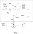
Fig. 5 is a schematic diagram illustrating functionality of a user interface of the pump when the pump is in the flush mode in accordance with an embodiment of the present disclosure. -
Figs. 1 and2 schematically depict aprogrammable infusion pump 10 embodying the present disclosure.Infusion pump 10 includes ahousing 12, a pump wheel orrotor 14 and acassette receptacle 16 on an external face of the housing, and a door (not shown) connected to the housing to open and close over the cassette receptacle and pump wheel. As shown inFig. 1 , anadministration set 18 is installed in association with the pump for carrying fluid from afluid source 19 to a patient. The administration set includes upstream tubing 4 running from thefluid source 19 to thepump 10,downstream tubing 8 running from the pump to a patient, acassette 5 received incassette receptacle 16, and a U-shaped tubing segment 6 arranged aroundpump wheel 14.Cassette 5 is configured withconnection terminals 5U and 5D for connecting upstream tubing 4 to an upstream end of tubing segment 6 anddownstream tubing 8 to a downstream end of tubing segment 6 to complete a flow path from the upstream tubing to the downstream tubing via the pump. -
Pump wheel 14 is part of a pumping mechanism operable to cause fluid flow through the tubing in an intended flow direction. The pumping mechanism further includes anelectric motor 20 connected topump wheel 14 and operable to rotate the pump wheel about its axis.Pump wheel 14 has radial fingers or rollers (not shown) that engage tubing segment 6 arranged about a circumferential portion of the wheel. Whenpump wheel 14 rotates, successive portions of tubing segment 6 are progressively squeezed to cause fluid to flow through the tubing in a flow direction toward the patient. The flow rate of infused fluid may be controlled by controlling the rate at whichmotor 20 is driven and/or the length oftime motor 20 is driven at a given rate. Those skilled in the art will understand that variations of the peristaltic pumping mechanism described above are possible. For example,motor 20 may drive a cam member connected to a series of parallel fingers or rollers arranged side-by-side, whereby peristaltic pumping action is applied to a straight segment of tubing instead of a curved segment of tubing as shown inFig. 1 . The present disclosure is not limited to a specific pumping mechanism configuration. -
Infusion pump 10 may include anupstream occlusion sensor 22 at a location along tubing segment 6 upstream from pumpingwheel 14 and adownstream occlusion sensor 24 at a location along tubing segment 6 downstream from pumpingwheel 14.Upstream sensor 22 anddownstream sensor 24 each provide a respective sensor signal indicative of a respective local fluid pressure in the tubing. For example, upstream anddownstream sensors -
Infusion pump 10 further includes an air-in-line (AIL)sensor 26 for detecting whether a volume of fluid observed by the sensor at a given time is air or liquid. In the present embodiment,AIL sensor 26 may comprise an ultrasonic transducer which includes a pair of piezoelectric ceramic elements 26A and 26B opposing each other across a portion of tubing segment 6. One ceramic element 26A is driven bymicroprocessor 30 at a frequency that sweeps through the resonance which lies within the frequency range. The ultrasonic energy is transmitted by element 26A into one side of the tubing and a portion of the energy is received by element 26B on the other side. If liquid is present in the tubing, the ultrasonic energy received by element 26B will be greater than a preset comparator threshold and is then converted into a logic level of "High". If air is present in the tubing, the medium for propagating the ultrasonic energy is less dense and the signal generated by element 26B is attenuated below the threshold and is converted into a logic level of "Low". Thus, in the embodiment just described, the amplitude of the ultrasonic energy which is received by element 26B is the main principle for determining the difference between liquid and air within the tubing. The tubing may be dry-coupled to the AIL sensor elements 26A and 26B; i.e. the sensor arrangement does not require the use of ultrasonic gel. As an alternative to ultrasonic AIL detection, an AIL sensor based on detection of optical properties of air and liquid media may be used. -
Infusion pump 10 is configured to permit a user to select and/or create, and then run, an infusion therapy protocol which may specify the rate at which the liquid is to be delivered to the patient. The protocol may be a "continuous therapy" protocol having no predefined total dosage amount, or the protocol may further specify the total amount of liquid to be delivered to the patient.Infusion pump 10 includes amicroprocessor 30 connected to auser interface 32 having input devices such as a keypad, switches and dial controls.Infusion pump 10 also includes adisplay 34 connected tomicroprocessor 30.Display 34 may be a touch screen display acting at times as part ofuser interface 32.Microprocessor 30 is connected to amotor controller 36 for drivingelectric motor 20 to administer a chosen therapy protocol. One ormore memory modules 38 are connected to or integrated withmicroprocessor 30 for storing instructions executable by the microprocessor for controlling pump operation. The stored instructions are organized in software routines. Among the stored software routines are routines that detect an end of therapy condition and enable the user to operatepump 10 in a flush mode to deliver residual liquid present withindownstream tubing 8 to the patient. These routines are described in detail below. For purposes of the present disclosure,microprocessor 30 may receive a signal fromAIL sensor 26. Alternatively, or additionally,microprocessor 30 may receive a signal from a liquid level or liquid volume sensor (not shown) associated withliquid source 19.Microprocessor 30 is also connected toupstream occlusion sensor 22 anddownstream occlusion sensor 24. Analog-to-digital conversion circuitry 23 is shown for converting the analog voltage signals from the occlusion sensors to digital form for use bymicroprocessor 30, however other forms of occlusion sensor and microprocessor interfaces may be used.Infusion pump 10 may also include anaudible signal generator 35 connected tomicroprocessor 30. -
Figs. 3-5 generally illustrate process flow and logic associated with a flush mode ofpump 10 according to an aspect of the present disclosure. As indicated inblock 40,microprocessor 30 may be programmed to present a choice to the user upon determining that an end of therapy condition has been reached. The end of therapy condition may be determined if the signal fromAIL sensor 26 indicates that an uninterrupted volume of air exceeding a predetermine threshold volume has passed through the interrogation zone of the AIL sensor.Microprocessor 30 may be programmed to issue an AIL alarm when this occurs. Alternatively, or additionally, determination of an end of therapy condition may be based on whether a liquid volume or liquid level inliquid source 19 has dropped below a threshold volume or level. The choice may be presented to the user by displaying a Confirm Flush message screen ondisplay 34 prompting the user to confirm that flushing mode operation is desired by pressing a specific key or button, for example the "+" button. - In
decision block 42, flow will branch depending upon which button of theuser interface 32 is pressed by the user. For example, if the "+" button is pressed, pump 10 will enter the flush mode and a Flushing screen may be displayed bydisplay 34 and an audible signal (e.g. a beep) may be issued byaudible signal generator 35. However, if the user presses the "-" button, the CLEAR button, or the RUN/PAUSE button, the software logic treats the therapy as completed and flush mode is not entered. - When
pump 10 is in the flush mode, the software causesmicroprocessor 30 to override the AIL alarm andcommand motor controller 36 to operatemotor 20 to deliver a predetermined volume of liquid corresponding to a volume of liquid expected to remain indownstream tubing 8. The predetermined delivery volume may be calculated based on the programmed threshold volume of air required to trigger the AIL alarm, and the total volume of the lumen running throughdownstream tubing 8, which is known from the use of an administration set 18 authorized and designed for use withpump 10. For example, ifpump 10 is applicant's INFINITY ORANGE® small volume enteral feeding pump used for infant feeding, the predetermined delivery volume may be set at 1.2 milliliters. - The predetermined delivery volume may be delivered in one continuous delivery until complete. However, it may be advantageous to deliver the predetermined delivery volume in increments, as indicated by
block 44 inFig. 3 , wherein the pump motor is commanded to stop after an increment is delivered.Decision block 46 branches flow back todecision block 42 for further input from the user, unless all increments have been delivered, in which case the therapy is ended. In this way, the user has an opportunity to cancel delivery of further increments if the liquid has already reached the end ofdownstream tubing 8. Breast milk in particular is foamy at the transition from milk to air, making it difficult to determine how far milk has been pumped down the tubing. By commanding the motor to deliver residual liquid in increments, the user is intentionally involved in the flush mode delivery. In the example illustrated byFig. 3 , the total predetermined delivery volume may be delivered in four equal increments. Of course,microprocessor 30 may be programmed to use a different number of pumping increments, and the pumping increments may vary in volume. - The user may also pause delivery in the flush mode while
motor 20 is operating by pressing the RUN/PAUSE button, and resume the delivery by again pressing the RUN/PAUSE button. - If an alarm (e.g. an occlusion alarm) is detected while the pump is delivering liquid in the flush mode, pumping may be paused and an alarm message may be displayed. In this case, the RUN/PAUSE button may be pressed to clear the alarm, and pressed again to resume flush mode pumping until the full residual amount is delivered.
- The remaining liquid may be delivered at the programmed delivery rate. Pump may also have a separate programmed rate to deliver the downstream volume, or the remaining liquid may be delivered at the same rate as priming.
- Once the additional pumping is finished,
microprocessor 30 may be programmed to display a Flush Done screen ondisplay 34 and issue another audible signal (e.g. another beep) by means ofaudible signal generator 35. If the Flush Done screen is showing and the user presses the RUN/PAUSE button, the programming instructions may treat the therapy as being ended. The residual delivery volume may count toward a programmed total dosage volume. If the total dosage volume is reached during the flush mode operation, the program instructions will stop the flush mode by causing a microprocessor to issue a motor stoppage command, and the software will consider the therapy ended. - As may be understood, the present disclosure may apply to an intravenous (IV) pump. As it is now, the liquid in the downstream tubing is discarded. The IV pump could use a similar algorithm to deliver the remaining liquid in the downstream tubing after an AIL condition is detected. If a specific dose is required of an IV pump, the pump may be programmed to deliver that dose minus the administration set priming volume, and then deliver the rest of the liquid according to the disclosed flush mode to achieve the correct dose. This would prevent the current need to discard the downstream volume of the drug.
- In a further embodiment,
microprocessor 30 may be programmed to enter the flush mode at the command of a user without having detected AIL. - Instead of delivering the remaining nutrition with whatever is currently in
downstream tubing 8, a flush switchover mechanism may be used to switch to hydration and deliver the remaining nutrition by pumping water. - In a further embodiment, an
AIL sensor 26 may be provided at the delivery end ofdownstream tubing 8 or at the opening of a gastrointestinal (GI) feeding tube connected to the patient to provide a signal tomicroprocessor 30, andmicroprocessor 30 may be programmed to automatically terminate the flush mode when a predetermined threshold volume of air is detected at the patient delivery end. - The present disclosure teaches methods and a pump apparatus configured by software programming to perform the methods. The disclosure teaches pump control algorithms which allow caregivers to use the last remaining liquid within downstream tubing. Example embodiments of the methods and pump apparatus of the present disclosure are described in detail herein, however those skilled in the art will realize that modifications may be made without straying from the scope of the disclosure.
Claims (7)
- A pumping system for delivering a liquid to a patient according to a predetermined therapy protocol, the pumping system comprising:a source of the liquid (19);an administration set (18) for carrying the liquid from the source to the patient, the administration set including a tubing segment (6), upstream tubing (4) communicating from the source to the tubing segment, and downstream tubing (8) communicating from the tubing segment to the patient;a pumping mechanism arranged to engage the tubing segment, the pumping mechanism including at least one pumping member (14), a motor (20) operable to actuate the at least one pumping member to peristaltically deform the tubing segment to force the liquid through the tubing segment in a direction from the upstream tubing toward the downstream tubing, and a motor controller (36) providing control commands to the motor;a processor (30) connected to the motor controller;a display (34) connected to the processor;at least one sensor associated with the administration set and/or the source for generating an end-of-therapy signal indicating an end-of-therapy condition, wherein the end-of-therapy signal is transmitted to the processor;at least one memory module (38) including stored program instructions executable by the processor for operating the motor to control operation of the pumping mechanism, wherein:the stored program instructions include a flush mode routine executable by the processor to operate the pumping mechanism in a flush mode to deliver residual liquid present within the downstream tubing to the patient after the processor receives the end-of-therapy signal, wherein execution of the flush mode routine is initiated in response to a user input action;the stored program instructions include an end-of-therapy routine executable by the processor to stop operation of the pumping mechanism and provide a prompt for the user input action on the display, wherein the end-of-therapy routine is executed in response to the end-of-therapy signal;execution of the flush mode routine delivers no more than a predetermined volume of liquid corresponding to a volume of liquid expected to remain in the downstream tubing after operation of the pumping mechanism is stopped in response to the end-of-therapy signal; andexecution of the flush mode routine delivers a first incremental portion of the predetermined volume of liquid and then pauses operation of the pumping mechanism, wherein delivery of a further incremental portion of the predetermined volume of liquid is initiated in response to another user input action and termination of the flush mode routine is carried out in response to a user input cancellation action.
- The pumping system according to claim 1, wherein the pumping mechanism, the processor, and the at least one memory module are part of an infusion pump (10) including a user interface (32) having a plurality of keys or buttons, wherein the user input action is pressing one of the keys or buttons.
- The pumping system according to claim 1, wherein execution of the flush mode routine delivers the entire predetermined volume of liquid in one continuous delivery unless execution of the flush mode routine is terminated.
- The pumping system according to claim 1, wherein execution of the flush mode routine pauses operation of the pumping mechanism in response to a user input pause action.
- The pumping system according to claim 1, wherein the at least one sensor includes an air-in-line sensor (26) associated with the tubing segment.
- The pumping system according to claim 1, wherein the at least one sensor includes a liquid level or liquid volume sensor associated with the liquid source.
- The pumping system according to claim 1, further comprising an air-in-line sensor (26) associated with a distal end of the downstream tubing and connected to the processor for automatically terminating execution of the flush mode routine when a predetermined threshold volume of air is detected by the air-in-line sensor.
Applications Claiming Priority (2)
| Application Number | Priority Date | Filing Date | Title |
|---|---|---|---|
| US201962822458P | 2019-03-22 | 2019-03-22 | |
| PCT/US2020/023240 WO2020197867A1 (en) | 2019-03-22 | 2020-03-18 | Method to deliver remaining liquid in an enteral or other infusion device |
Publications (4)
| Publication Number | Publication Date |
|---|---|
| EP3942182A1 EP3942182A1 (en) | 2022-01-26 |
| EP3942182A4 EP3942182A4 (en) | 2022-11-23 |
| EP3942182B1 true EP3942182B1 (en) | 2025-02-12 |
| EP3942182C0 EP3942182C0 (en) | 2025-02-12 |
Family
ID=72611070
Family Applications (1)
| Application Number | Title | Priority Date | Filing Date |
|---|---|---|---|
| EP20777088.4A Active EP3942182B1 (en) | 2019-03-22 | 2020-03-18 | Method to deliver remaining liquid in an enteral or other infusion device |
Country Status (10)
| Country | Link |
|---|---|
| US (1) | US20220152299A1 (en) |
| EP (1) | EP3942182B1 (en) |
| JP (1) | JP7281554B2 (en) |
| KR (1) | KR102638062B1 (en) |
| CN (1) | CN113614375B (en) |
| AU (1) | AU2020245304B2 (en) |
| CA (1) | CA3133301C (en) |
| ES (1) | ES3025407T3 (en) |
| IL (1) | IL285945B2 (en) |
| WO (1) | WO2020197867A1 (en) |
Families Citing this family (2)
| Publication number | Priority date | Publication date | Assignee | Title |
|---|---|---|---|---|
| CN117957370A (en) | 2021-07-23 | 2024-04-30 | 沃特世科技公司 | Peristaltic pump with temperature compensated volume delivery |
| US20260083640A1 (en) * | 2024-09-25 | 2026-03-26 | Medela Holding Ag | Method for Operating a Feeding System for Feeding a Patient with a Liquid Feed |
Family Cites Families (15)
| Publication number | Priority date | Publication date | Assignee | Title |
|---|---|---|---|---|
| DE4336336A1 (en) * | 1992-11-23 | 1994-05-26 | Lang Volker | Cassette infusion system |
| US6852090B2 (en) * | 1997-02-14 | 2005-02-08 | Nxstage Medical, Inc. | Fluid processing systems and methods using extracorporeal fluid flow panels oriented within a cartridge |
| US6339718B1 (en) | 1999-07-30 | 2002-01-15 | Medrad, Inc. | Programmable injector control |
| IL141137A0 (en) * | 2001-01-28 | 2002-02-10 | Caesaria Med Electronics Ltd | Liquid pump |
| JP2006522658A (en) * | 2003-04-08 | 2006-10-05 | メドラッド インコーポレーテッド | Fluid transport system, fluid transport device, and method for transporting hazardous fluid |
| CA2553681A1 (en) * | 2004-02-10 | 2005-08-25 | Synecor, Llc | Intravascular delivery system for therapeutic agents |
| US20080119822A1 (en) * | 2006-11-17 | 2008-05-22 | Tyco Healthcare Group Lp | Enteral fluid delivery system and method for opeating the same |
| ES3038412T3 (en) * | 2007-05-11 | 2025-10-13 | Hoffmann La Roche | A positive displacement pump |
| US8348844B2 (en) * | 2008-12-02 | 2013-01-08 | Kislaya Kunjan | Automated blood sampler and analyzer |
| JP5897582B2 (en) * | 2010-10-01 | 2016-03-30 | スミス・メディカル・エイエスディ・インコーポレーテッド | Cleaning fluid lines from medical pumps |
| US8876793B2 (en) * | 2010-10-01 | 2014-11-04 | Smiths Medical Asd, Inc. | Flushing a fluid line from a medical pump |
| US9408968B2 (en) * | 2012-06-24 | 2016-08-09 | Zevex, Inc. | Method and apparatus for detection and management of air-in-line |
| ES2838450T3 (en) | 2013-05-29 | 2021-07-02 | Icu Medical Inc | Infusion set that uses one or more sensors and additional information to make an air determination relative to the infusion set |
| US10292908B2 (en) * | 2014-08-01 | 2019-05-21 | Medela Holding Ag | Neonatal enteral feeding system |
| US10940096B2 (en) * | 2016-04-05 | 2021-03-09 | Medela Holding Ag | Enteral feeding air purge system and method |
-
2020
- 2020-03-18 CA CA3133301A patent/CA3133301C/en active Active
- 2020-03-18 US US17/432,968 patent/US20220152299A1/en active Pending
- 2020-03-18 ES ES20777088T patent/ES3025407T3/en active Active
- 2020-03-18 EP EP20777088.4A patent/EP3942182B1/en active Active
- 2020-03-18 KR KR1020217029764A patent/KR102638062B1/en active Active
- 2020-03-18 AU AU2020245304A patent/AU2020245304B2/en active Active
- 2020-03-18 IL IL285945A patent/IL285945B2/en unknown
- 2020-03-18 WO PCT/US2020/023240 patent/WO2020197867A1/en not_active Ceased
- 2020-03-18 JP JP2021553804A patent/JP7281554B2/en active Active
- 2020-03-18 CN CN202080023313.2A patent/CN113614375B/en active Active
Also Published As
| Publication number | Publication date |
|---|---|
| IL285945A (en) | 2021-10-31 |
| ES3025407T3 (en) | 2025-06-09 |
| BR112021017263A2 (en) | 2021-11-09 |
| IL285945B1 (en) | 2024-11-01 |
| EP3942182C0 (en) | 2025-02-12 |
| KR20210130183A (en) | 2021-10-29 |
| JP2022524396A (en) | 2022-05-02 |
| AU2020245304B2 (en) | 2023-05-11 |
| WO2020197867A1 (en) | 2020-10-01 |
| CA3133301A1 (en) | 2020-10-01 |
| AU2020245304A1 (en) | 2021-09-30 |
| CN113614375B (en) | 2023-08-22 |
| EP3942182A1 (en) | 2022-01-26 |
| KR102638062B1 (en) | 2024-02-21 |
| CA3133301C (en) | 2024-01-23 |
| EP3942182A4 (en) | 2022-11-23 |
| JP7281554B2 (en) | 2023-05-25 |
| CN113614375A (en) | 2021-11-05 |
| IL285945B2 (en) | 2025-03-01 |
| US20220152299A1 (en) | 2022-05-19 |
Similar Documents
| Publication | Publication Date | Title |
|---|---|---|
| EP2741800B1 (en) | Apparatus for detection and management of air-in-line | |
| TWI907805B (en) | Systems and methods for substantially continuous intravenous infusion of the same or substantially the same medical fluid with fluid source replacements | |
| EP2384207B1 (en) | Medical injection device with electric motor drive control | |
| EP3576811B1 (en) | Acoustic frequency recognition of patient lines | |
| JP2005537116A (en) | Dosing device with temperature sensor | |
| JP6914848B2 (en) | Medical pump and its control method | |
| CA3133301C (en) | Method to deliver remaining liquid in an enteral or other infusion device | |
| JP2022504223A (en) | Injection pump and injection pump operation | |
| BR112021017263B1 (en) | PUMPING SYSTEM | |
| RU2799790C2 (en) | Infusion pump and infusion pump operations | |
| EP3498324B1 (en) | Method for operating a drug delivery system and drug delivery system |
Legal Events
| Date | Code | Title | Description |
|---|---|---|---|
| STAA | Information on the status of an ep patent application or granted ep patent |
Free format text: STATUS: THE INTERNATIONAL PUBLICATION HAS BEEN MADE |
|
| PUAI | Public reference made under article 153(3) epc to a published international application that has entered the european phase |
Free format text: ORIGINAL CODE: 0009012 |
|
| STAA | Information on the status of an ep patent application or granted ep patent |
Free format text: STATUS: REQUEST FOR EXAMINATION WAS MADE |
|
| 17P | Request for examination filed |
Effective date: 20210826 |
|
| AK | Designated contracting states |
Kind code of ref document: A1 Designated state(s): AL AT BE BG CH CY CZ DE DK EE ES FI FR GB GR HR HU IE IS IT LI LT LU LV MC MK MT NL NO PL PT RO RS SE SI SK SM TR |
|
| DAV | Request for validation of the european patent (deleted) | ||
| DAX | Request for extension of the european patent (deleted) | ||
| A4 | Supplementary search report drawn up and despatched |
Effective date: 20221024 |
|
| RIC1 | Information provided on ipc code assigned before grant |
Ipc: A61M 39/22 20060101ALN20221019BHEP Ipc: A61M 5/14 20060101ALN20221019BHEP Ipc: A61J 15/00 20060101ALI20221019BHEP Ipc: A61M 5/168 20060101ALI20221019BHEP Ipc: A61M 5/142 20060101ALI20221019BHEP Ipc: F04B 49/06 20060101AFI20221019BHEP |
|
| RIC1 | Information provided on ipc code assigned before grant |
Ipc: A61M 39/22 20060101ALN20240813BHEP Ipc: A61M 5/14 20060101ALN20240813BHEP Ipc: A61J 15/00 20060101ALI20240813BHEP Ipc: A61M 5/168 20060101ALI20240813BHEP Ipc: A61M 5/142 20060101ALI20240813BHEP Ipc: F04B 49/06 20060101AFI20240813BHEP |
|
| GRAP | Despatch of communication of intention to grant a patent |
Free format text: ORIGINAL CODE: EPIDOSNIGR1 |
|
| STAA | Information on the status of an ep patent application or granted ep patent |
Free format text: STATUS: GRANT OF PATENT IS INTENDED |
|
| INTG | Intention to grant announced |
Effective date: 20240923 |
|
| RIN1 | Information on inventor provided before grant (corrected) |
Inventor name: THORNE, DAVID Inventor name: BACON, JOHN Inventor name: GEISLER, JEFFREY D. Inventor name: JURETICH, JEFFERY T. |
|
| GRAS | Grant fee paid |
Free format text: ORIGINAL CODE: EPIDOSNIGR3 |
|
| GRAA | (expected) grant |
Free format text: ORIGINAL CODE: 0009210 |
|
| STAA | Information on the status of an ep patent application or granted ep patent |
Free format text: STATUS: THE PATENT HAS BEEN GRANTED |
|
| AK | Designated contracting states |
Kind code of ref document: B1 Designated state(s): AL AT BE BG CH CY CZ DE DK EE ES FI FR GB GR HR HU IE IS IT LI LT LU LV MC MK MT NL NO PL PT RO RS SE SI SK SM TR |
|
| REG | Reference to a national code |
Ref country code: GB Ref legal event code: FG4D |
|
| REG | Reference to a national code |
Ref country code: CH Ref legal event code: EP |
|
| REG | Reference to a national code |
Ref country code: DE Ref legal event code: R096 Ref document number: 602020045961 Country of ref document: DE |
|
| REG | Reference to a national code |
Ref country code: IE Ref legal event code: FG4D |
|
| U01 | Request for unitary effect filed |
Effective date: 20250310 |
|
| U07 | Unitary effect registered |
Designated state(s): AT BE BG DE DK EE FI FR IT LT LU LV MT NL PT RO SE SI Effective date: 20250317 |
|
| REG | Reference to a national code |
Ref country code: ES Ref legal event code: FG2A Ref document number: 3025407 Country of ref document: ES Kind code of ref document: T3 Effective date: 20250609 |
|
| U20 | Renewal fee for the european patent with unitary effect paid |
Year of fee payment: 6 Effective date: 20250509 |
|
| PG25 | Lapsed in a contracting state [announced via postgrant information from national office to epo] |
Ref country code: RS Free format text: LAPSE BECAUSE OF FAILURE TO SUBMIT A TRANSLATION OF THE DESCRIPTION OR TO PAY THE FEE WITHIN THE PRESCRIBED TIME-LIMIT Effective date: 20250512 |
|
| PG25 | Lapsed in a contracting state [announced via postgrant information from national office to epo] |
Ref country code: PL Free format text: LAPSE BECAUSE OF FAILURE TO SUBMIT A TRANSLATION OF THE DESCRIPTION OR TO PAY THE FEE WITHIN THE PRESCRIBED TIME-LIMIT Effective date: 20250212 |
|
| PGFP | Annual fee paid to national office [announced via postgrant information from national office to epo] |
Ref country code: ES Payment date: 20250528 Year of fee payment: 6 |
|
| PG25 | Lapsed in a contracting state [announced via postgrant information from national office to epo] |
Ref country code: IS Free format text: LAPSE BECAUSE OF FAILURE TO SUBMIT A TRANSLATION OF THE DESCRIPTION OR TO PAY THE FEE WITHIN THE PRESCRIBED TIME-LIMIT Effective date: 20250612 Ref country code: NO Free format text: LAPSE BECAUSE OF FAILURE TO SUBMIT A TRANSLATION OF THE DESCRIPTION OR TO PAY THE FEE WITHIN THE PRESCRIBED TIME-LIMIT Effective date: 20250512 |
|
| PG25 | Lapsed in a contracting state [announced via postgrant information from national office to epo] |
Ref country code: HR Free format text: LAPSE BECAUSE OF FAILURE TO SUBMIT A TRANSLATION OF THE DESCRIPTION OR TO PAY THE FEE WITHIN THE PRESCRIBED TIME-LIMIT Effective date: 20250212 |
|
| PG25 | Lapsed in a contracting state [announced via postgrant information from national office to epo] |
Ref country code: GR Free format text: LAPSE BECAUSE OF FAILURE TO SUBMIT A TRANSLATION OF THE DESCRIPTION OR TO PAY THE FEE WITHIN THE PRESCRIBED TIME-LIMIT Effective date: 20250513 |
|
| PGFP | Annual fee paid to national office [announced via postgrant information from national office to epo] |
Ref country code: CH Payment date: 20250520 Year of fee payment: 6 |
|
| PG25 | Lapsed in a contracting state [announced via postgrant information from national office to epo] |
Ref country code: SM Free format text: LAPSE BECAUSE OF FAILURE TO SUBMIT A TRANSLATION OF THE DESCRIPTION OR TO PAY THE FEE WITHIN THE PRESCRIBED TIME-LIMIT Effective date: 20250212 |
|
| PG25 | Lapsed in a contracting state [announced via postgrant information from national office to epo] |
Ref country code: CZ Free format text: LAPSE BECAUSE OF FAILURE TO SUBMIT A TRANSLATION OF THE DESCRIPTION OR TO PAY THE FEE WITHIN THE PRESCRIBED TIME-LIMIT Effective date: 20250212 |
|
| PG25 | Lapsed in a contracting state [announced via postgrant information from national office to epo] |
Ref country code: SK Free format text: LAPSE BECAUSE OF FAILURE TO SUBMIT A TRANSLATION OF THE DESCRIPTION OR TO PAY THE FEE WITHIN THE PRESCRIBED TIME-LIMIT Effective date: 20250212 |
|
| PLBE | No opposition filed within time limit |
Free format text: ORIGINAL CODE: 0009261 |
|
| STAA | Information on the status of an ep patent application or granted ep patent |
Free format text: STATUS: NO OPPOSITION FILED WITHIN TIME LIMIT |
|
| PG25 | Lapsed in a contracting state [announced via postgrant information from national office to epo] |
Ref country code: MC Free format text: LAPSE BECAUSE OF FAILURE TO SUBMIT A TRANSLATION OF THE DESCRIPTION OR TO PAY THE FEE WITHIN THE PRESCRIBED TIME-LIMIT Effective date: 20250212 |
|
| REG | Reference to a national code |
Ref country code: CH Ref legal event code: L10 Free format text: ST27 STATUS EVENT CODE: U-0-0-L10-L00 (AS PROVIDED BY THE NATIONAL OFFICE) Effective date: 20251224 |
|
| 26N | No opposition filed |
Effective date: 20251113 |
|
| U20 | Renewal fee for the european patent with unitary effect paid |
Year of fee payment: 7 Effective date: 20260218 |
|
| REG | Reference to a national code |
Ref country code: CH Ref legal event code: U11 Free format text: ST27 STATUS EVENT CODE: U-0-0-U10-U11 (AS PROVIDED BY THE NATIONAL OFFICE) Effective date: 20260401 |
|
| PGFP | Annual fee paid to national office [announced via postgrant information from national office to epo] |
Ref country code: GB Payment date: 20260216 Year of fee payment: 7 |
|
| PGFP | Annual fee paid to national office [announced via postgrant information from national office to epo] |
Ref country code: IE Payment date: 20260224 Year of fee payment: 7 |