EP3942144B1 - Method to longitudinally and circumferential cut out and remove a section of a wellbore tubular - Google Patents
Method to longitudinally and circumferential cut out and remove a section of a wellbore tubular Download PDFInfo
- Publication number
- EP3942144B1 EP3942144B1 EP20720929.7A EP20720929A EP3942144B1 EP 3942144 B1 EP3942144 B1 EP 3942144B1 EP 20720929 A EP20720929 A EP 20720929A EP 3942144 B1 EP3942144 B1 EP 3942144B1
- Authority
- EP
- European Patent Office
- Prior art keywords
- tubular
- cut
- wellbore
- wellbore tubular
- push
- Prior art date
- Legal status (The legal status is an assumption and is not a legal conclusion. Google has not performed a legal analysis and makes no representation as to the accuracy of the status listed.)
- Active
Links
Images


Classifications
-
- E—FIXED CONSTRUCTIONS
- E21—EARTH OR ROCK DRILLING; MINING
- E21B—EARTH OR ROCK DRILLING; OBTAINING OIL, GAS, WATER, SOLUBLE OR MELTABLE MATERIALS OR A SLURRY OF MINERALS FROM WELLS
- E21B29/00—Cutting or destroying pipes, packers, plugs or wire lines, located in boreholes or wells, e.g. cutting of damaged pipes, of windows; Deforming of pipes in boreholes or wells; Reconditioning of well casings while in the ground
-
- E—FIXED CONSTRUCTIONS
- E21—EARTH OR ROCK DRILLING; MINING
- E21B—EARTH OR ROCK DRILLING; OBTAINING OIL, GAS, WATER, SOLUBLE OR MELTABLE MATERIALS OR A SLURRY OF MINERALS FROM WELLS
- E21B23/00—Apparatus for displacing, setting, locking, releasing or removing tools, packers or the like in boreholes or wells
- E21B23/01—Apparatus for displacing, setting, locking, releasing or removing tools, packers or the like in boreholes or wells for anchoring the tools or the like
-
- E—FIXED CONSTRUCTIONS
- E21—EARTH OR ROCK DRILLING; MINING
- E21B—EARTH OR ROCK DRILLING; OBTAINING OIL, GAS, WATER, SOLUBLE OR MELTABLE MATERIALS OR A SLURRY OF MINERALS FROM WELLS
- E21B29/00—Cutting or destroying pipes, packers, plugs or wire lines, located in boreholes or wells, e.g. cutting of damaged pipes, of windows; Deforming of pipes in boreholes or wells; Reconditioning of well casings while in the ground
- E21B29/02—Cutting or destroying pipes, packers, plugs or wire lines, located in boreholes or wells, e.g. cutting of damaged pipes, of windows; Deforming of pipes in boreholes or wells; Reconditioning of well casings while in the ground by explosives or by thermal or chemical means
-
- E—FIXED CONSTRUCTIONS
- E21—EARTH OR ROCK DRILLING; MINING
- E21B—EARTH OR ROCK DRILLING; OBTAINING OIL, GAS, WATER, SOLUBLE OR MELTABLE MATERIALS OR A SLURRY OF MINERALS FROM WELLS
- E21B29/00—Cutting or destroying pipes, packers, plugs or wire lines, located in boreholes or wells, e.g. cutting of damaged pipes, of windows; Deforming of pipes in boreholes or wells; Reconditioning of well casings while in the ground
- E21B29/06—Cutting windows, e.g. directional window cutters for whipstock operations
-
- E—FIXED CONSTRUCTIONS
- E21—EARTH OR ROCK DRILLING; MINING
- E21B—EARTH OR ROCK DRILLING; OBTAINING OIL, GAS, WATER, SOLUBLE OR MELTABLE MATERIALS OR A SLURRY OF MINERALS FROM WELLS
- E21B4/00—Drives for drilling, used in the borehole
- E21B4/18—Anchoring or feeding in the borehole
Definitions
- This disclosure relates to the field of abandonment of subsurface wells. More specifically, the disclosure relates to cutting and removing sections of wellbore tubular elements, e.g., casing and tubing, during a procedure to plug and abandon a subsurface well.
- Documents US2007251692 and WO2014117846 disclose devices for cutting wellbore tubulars.
- Permanent wellbore abandonment includes so-called plug and abandonment (P&A) procedures. Such procedures are used for prevention of fluid leaks into the environment and subsequent contamination of other underground areas and are important for preventing future costly repairs, environmental remediation and damage to the business reputation of the well owner, among other characteristics. It is observed in the oil and gas industry that high importance is placed on setting and verifying in-well ("downhole") fluid barriers, while lowering the cost of the abandonment by performing increasing amounts of abandonment work using small, light-weight and less costly wellbore intervention equipment rather than the use of larger footprint, costly to operate well drilling units.
- P&A plug and abandonment
- tubulars Possible leaks outside and between wellbore conduit (“tubulars") installed in a well must be prevented, and therefore existing barriers must be verified or new barriers need to be established and verified, prior to permanently leaving the tubulars in the ground at the time the well is to be abandoned.
- a production tubing string (a nested conduit inside a wellbore casing) is pulled out of the well to enable good placement and verification of barriers within or externally to the wellbore casing, that is, the conduit or tubular generally adjacent to the originally drilled wellbore.
- barriers may comprise cement placed in an annular space between the casing and the drilled borehole.
- Barrier verification may comprise making measurements such as acoustic cement bond verification.
- HSE health, safety and environmental
- the present invention refers to an apparatus for cutting sections of a wellbore tubular according to the features specified in claim 1 and to a method for cutting a wellbore tubular according to the features of claim 7.
- An apparatus for cutting sections of a wellbore tubular includes a housing shaped to enable movement along an interior of the wellbore tubular.
- the housing has an upper end arranged to connect to a conveyance and a lower end comprising a guide.
- Cutting materials are disposed in the housing and are arranged to cut the wellbore tubular in at least one circumferential cut and at least one longitudinal cut.
- the cutting materials comprise explosive cutters.
- the cutting materials comprise chemical cutters.
- the housing comprises at least one push-out module.
- Some embodiments further comprise at least one of a push-out module and a push in module disposed between the upper end and the guide and is arranged to contact the tubular to at least one of radially expand the tubular and radially contract the tubular.
- the at least one push out module comprises a hydraulic ram/cylinder combination.
- Some embodiments further comprise a plurality of longitudinally spaced apart push out modules.
- the cutting materials are arranged to cut the wellbore tubular along a plurality of longitudinal cuts extending between the circumferential cuts.
- Some embodiments further comprise a push down module.
- the push down module comprises at least one radially extensible arm for engaging a longitudinal end of a wellbore tubular severed by the cutting materials.
- the at least one arm is urged radially outward from the housing by a biasing device.
- the biasing device comprises a spring.
- the cutting materials are arranged to cut the wellbore tubular in at least a second circumferential cut longitudinally spaced apart from the at least one circumferential cut by a distance corresponding to a length of the at least one longitudinal cut.
- a method for cutting a wellbore tubular comprises positioning a tool in the wellbore tubular at a selected depth.
- the tool comprises a housing shaped to enable movement along an interior of the wellbore tubular.
- the housing has an upper end arranged to connect to a conveyance and a lower end comprising a guide.
- Cutting materials disposed in the housing are arranged to cut the wellbore tubular in two, longitudinally spaced apart circumferential cuts and at least one longitudinal cut extending between the circumferential cuts.
- Some embodiments further comprise actuating the cutting materials to create a plurality of longitudinal cuts in the wellbore tubular.
- Some embodiments further comprise at least one of a push-out module and a push in module is disposed between the upper end and the guide and arranged to contact the tubular to at least one of radially expand the tubular and radially contract the tubular.
- Some embodiments further comprise actuating the push-out module to radially expand the wellbore tubular to enable dropping the cut section over the wellbore tubular below the lower circumferential cut.
- Some embodiments further comprise conducting at least one well intervention operation through an opening created by cutting the wellbore tubular.
- the push-out module and a pull in module is operated with sufficient force to lift the tubular from a wall of a conduit in which the tubular is nested.
- Some embodiments further comprise moving a push down module to a position above a position of a tubular severed by the actuating the cutting materials.
- the push down module comprises at least one radially extensible arm for engaging a longitudinal end of a wellbore tubular severed by the cutting materials.
- the at least one arm is urged radially outward from the housing by a biasing device.
- the biasing device comprises a spring.
- Some embodiments further comprise actuating further cutting materials to make at least one additional longitudinal cut beginning at a longitudinal end of severed wellbore tubular and actuating the further cutting materials to make at least one additional circumferential cut proximate a longitudinal end of the at least one additional longitudinal cut.
- a tool to perform such cutting may be designed such that the lower part of the tool protrudes below the lowest circumferential cut, and enables the tool to laterally lift the remaining, cut tubular clear of the inner wall of an externally disposed, nested tubular.
- FIG. 1 illustrates a wellbore intervention tool 10 that can be deployed by a conveyance, e.g., an electric cable 14 (wireline) as shown, by a spoolable, semi-stiff rod having electrical power and signal capabilities, or by coiled tubing having an electric cable implemented.
- the wellbore intervention tool 10 may be deployed into a tubing 30 having an external diameter of, for example, 31 ⁇ 2 inches (89 cm).
- the tubing 30 may be nested within a casing 20 having an external diameter of 9 5/8 inches (245 cm).
- casing and tubing dimensions are only example dimensions, and such dimensions will vary from well to well. Accordingly, such dimensions are not to be construed as a limit on the scope of the present disclosure; any other dimensions for wellbore tubulars are within the scope of the present disclosure.
- the wellbore intervention tool 10 may comprise, in its upper section, a cable head 10A or similar connector for electrical and mechanical connection to a deployment device (e.g., an armored electrical cable 14), and optionally an emergency release (associated with the cable head 10A, not shown separately).
- a guide nose 10B may be disposed in the lower end of the wellbore intervention tool 10.
- An actuation module 12 forming part of the wellbore intervention tool 10 may comprise control circuits (not shown separately) for actuating explosive and/or chemical cutting materials and actuating one or more push-out modules 18.
- the cutting materials may be disposed, for example, in a cutting materials module 60.
- the placement of the cutting materials in such cutting materials module 60 may be chosen according to intended cut pattern of the tubular in which the wellbore intervention tool 10 is deployed.
- the present example embodiment contemplates a combination of cutting materials arranged on the wellbore intervention tool 10 for both longitudinal and circumferential cutting.
- the circumferential and longitudinal cuts may be performed simultaneously, or with a chosen time delay between them to optimize the energy created when cutting.
- two circumferential cutter discharge ports 16B may provide that the cutting materials create longitudinally spaced apart, circumferential cuts in the tubing 30 (or other well tubular) when actuated.
- a longitudinal cutter discharge port 16A may enable making a longitudinal cut in the tubing 30 that extends between the circumferential cuts made through the circumferential discharge ports 16A.
- a section of a wellbore tubular e.g., the tubing 30
- at least one longitudinal cut and two circumferential cuts are made using the illustrated embodiment.
- Other embodiments may comprise two or more such longitudinal discharge ports 16A disposed at circumferentially spaced apart positions to create two or more such longitudinal cuts in the tubular.
- the wellbore intervention tool 10 may comprise one or more push-out modules 18.
- Three such modules are shown in FIG. 1 , each comprising apparatus that can extend laterally and push outward against the tubular (e.g., tubing 30) in which the wellbore intervention tool 10 is deployed.
- the push-out modules 18 may comprise any mechanism to extend laterally from the wellbore intervention tool 10 and retract, for example and without limitation, hydraulic ram/cylinder combinations, motor/jack screw combinations or any similar devices.
- the push-out modules 18 may be extended after deploying the wellbore intervention tool 10 to a required operating depth, or such modules 18 may be activated after initiating tubular cutting operations.
- the push-out modules 18 may comprise rollers, wheels or similar devices on their extending elements to reduce friction between the push-out modules 18 and the interior wall of the tubular (e.g., tubing 30).
- the push-out modules 18 may be substituted by pull-in modules which pull cut tubular sections inward into the interior of the cut tubular, followed by release and dropping of the cut tubular sections into the tubular below the depth of the wellbore intervention tool 10.
- the lowermost push-out/pull in module(s) may be activated first followed by activation of the push-out/pull module(s) above or by activating the uppermost push-out/pull module(s) first followed by the lower push-out/pull module(s), etc.
- Pull-in modules may comprise electromagnets, tubular wall penetrating "spears", suction cups or similar devices that can attach to or otherwise affix to the tubular and urge such tubular toward the wellbore intervention tool 10 when the pull in module is retracted.
- the push-out module(s) 18 when actuated may spread the tubular (e.g., tubing 30) along the longitudinal cuts after the cutting materials are actuated.
- a wellbore intervention tool as shown in FIG. 1 may be used as further explained below.
- the push out module(s) 18 may be disposed longitudinally along the wellbore intervention tool 10 between the spaced apart circumferential discharge ports 16B.
- Some embodiments of the wellbore intervention tool may comprise only one circumferential discharge port 16B. Such embodiments may be used, among other purposes, to sever additional segments of wellbore tubular as will be further explained below.
- the present example embodiment may comprise a guide 22 on the longitudinal end opposite the end connected to the cable 14.
- the guide 22 may comprise one or more rollers 22A to reduce friction when the wellbore intervention tool 10 is moved along the interior of a wellbore tubular.
- FIG. 2 illustrates the wellbore intervention tool 10 deployed to a chosen depth where tubular cutting is to be performed.
- FIG. 3 illustrates that longitudinal and circumferential cuts, C1, C2, respectively have been completed by actuating the cutting materials in the cutting material module 60, followed by operation (in this case) extension of the push-out modules 18.
- Extension of the push-out modules 18 after cutting the tubular e.g., tubing 30
- the cut-out section 30A being radially expanded toward the surrounding casing 20, while the tubing 30 above and below the cuts C1, C2 will be laterally moved (lifted in an inclined well) away from the casing 20.
- Such movement will allow the cut tubing section 30A to be dropped outside the upper end of the remaining uncut tubing 30C, located below the cut section (i.e., below cut C2 in FIG. 3 ).
- FIG. 4 illustrates that the cut out tubular section 30A is sliding or dropping down into the well, external to the tubing 30 below where the lower circumferential cut C2 was made, and thus into the annular space A.
- FIG. 5 illustrates that the cut tubular section 30A has dropped down, the push-out modules 18 have been retracted, and that the wellbore intervention tool 10 can be retrieved to the surface, e.g., by retracting the cable (14 in FIG. 1 ).
- FIG. 6 illustrates the wellbore intervention tool 10 has been removed from the tubing 30, and that a section of well tubular (tubing 30) has been removed so that access along a path 50 to the interior of the outer tubular (casing 20) is provided for logging instruments and other required intervention tools.
- at least one wellbore intervention operation may be conducted in the annular space A through the path 50.
- Such operation may comprise, e.g., wireline logging, among other operations.
- FIG. 7 illustrates an example embodiment of a method where the tubular has only one longitudinal cut L, where the cut section of tubular 30A is radially expanded to a size large enough to be dropped or pushed over the cut tubular (e.g., tubing 30) located below the lower circumferential cut (C2 in FIG. 3 ).
- the cut tubular e.g., tubing 30
- One tubular section may be of a length of, for example, 10-12 meters, while there may be requirements to remove up to 100 meters of tubular.
- a tool as herein described may also be configured for longer than 10-12 meter cuts, e.g., by increasing the longitudinal spacing between the circumferential discharge ports (16A in FIG. 1 ).
- FIG. 8 shows another example embodiment of the wellbore intervention tool 10.
- the present example embodiment of the wellbore intervention tool 10 may be similarly configured as the embodiment explained with reference to FIG. 1 but with the following differences.
- the present example embodiment of the wellbore intervention tool 10 may comprise, instead of the guide (22 in FIG. 1 ) at one longitudinal end, a push down module 70.
- the push down module 70 may comprise components, to be explained further below, that engage the top of a severed wellbore tubular to enable the wellbore intervention tool to apply axial force to the severed section in order to move it away from the remainder of the wellbore tubular.
- the present example embodiment may omit the one or more push out (or pull in) modules explained above (18 in FIG. 1
- FIG. 9 shows the example embodiment of FIG. 8 wherein a wellbore tubular is cut.
- the cut tubular is tubing 30, as in the previously explained embodiments.
- Actuation of the cutting materials in the cuttings material module 60 may make two or more longitudinally spaced apart circumferential cuts in the tubing 30 (or any other wellbore tubular to be severed). Shock wave from detonating the cutting materials may expand the severed section 30A of the wellbore tubular 30 radially so that it is larger in expanded diameter than the outer diameter of the remainder of the wellbore tubular.
- FIG. 10 shows the example embodiment of FIG. 8 lifted above the severed tubular 30A in FIG. 9 to deploy the push down module 70.
- the push down module 70 may comprise one or more arms 72 pivotally coupled to the wellbore intervention tool 10. Each arm 72 may be urged to radially extend from the wellbore intervention tool 10 by a biasing device 74 such as a spring or hydraulic cylinder.
- a biasing device 74 such as a spring or hydraulic cylinder.
- the arm(s) 72 extend radially as shown in FIG. 10 to enable engagement of the extended arm(s) 72 with the top of the severed tubular 30A.
- the wellbore intervention tool 10 may then be moved downward in the well to urge the severed tubular 30A downward in the annular space A.).
- the push down module 60 is shown proximate the lower end of the wellbore intervention tool 10, for purposes of defining the scope of the present disclosure, it is only necessary that the push down module 60 be located so that the arm 72 remains compressed until which time it is desired to radially expand the arm 72 to enable push down of the severed wellbore tubular.
- the push down module 60 could be located axially proximate the actuator module 12.
- severing the wellbore tubular would not immediately result in radial expansion of the arm 72.
- the arm 72 will expand radially such that it engages the top of the severed section 30A of the wellbore tubular.
- FIG. 11 shows the well of FIGS. 8 through 10 wherein the cut tubular 30A has been pushed out of the way to leave an opening 31 in the wellbore tubular 30.
- the opening 31 may provide access to the interior wall of the tubular, e.g., the casing 20, in which the wellbore tubular 30 is nested for subsequent intervention operations such as logging or perforating.
- the severed tubular may be deformed or pushed outward into the annular space 50 by energy from operation of the cutting materials.
- Such outward pushing may enable severed segments of the tubular (e.g., tubing 30) to drop below the upper end 30D in FIG. 11 of the lower part of the severed tubular, either by gravity alone or using the push down module as explained with reference to FIGS, 8 through 10 .
- FIG. 1 may comprise only one circumferential discharge port 16B.
- Such embodiments may be configured as explained with reference to FIG. 1 or FIG. 8 .
- Such embodiments may be used to sever additional segments of tubular, for example, by making one or more longitudinal cuts in the tubular from the bottom 30C of the several tubular 30 extending upwardly, or from the top 30D of the severed tubular extending downwardly.
- Such longitudinal cut(s) may be accompanied by a circumferential cut proximate the longitudinal end of the longitudinal cut(s) to sever an additional segment of the tubular 30. The foregoing procedure may be repeated until a chosen length of the tubular 30 is severed and displaced.
Landscapes
- Engineering & Computer Science (AREA)
- Geology (AREA)
- Life Sciences & Earth Sciences (AREA)
- Mining & Mineral Resources (AREA)
- Geochemistry & Mineralogy (AREA)
- Fluid Mechanics (AREA)
- Environmental & Geological Engineering (AREA)
- General Life Sciences & Earth Sciences (AREA)
- Physics & Mathematics (AREA)
- Chemical & Material Sciences (AREA)
- Chemical Kinetics & Catalysis (AREA)
- General Chemical & Material Sciences (AREA)
- Mechanical Engineering (AREA)
- Excavating Of Shafts Or Tunnels (AREA)
- Earth Drilling (AREA)
- Manufacturing Of Tubular Articles Or Embedded Moulded Articles (AREA)
- Processing Of Stones Or Stones Resemblance Materials (AREA)
Description
- This disclosure relates to the field of abandonment of subsurface wells. More specifically, the disclosure relates to cutting and removing sections of wellbore tubular elements, e.g., casing and tubing, during a procedure to plug and abandon a subsurface well. Documents
US2007251692 andWO2014117846 disclose devices for cutting wellbore tubulars. - Permanent wellbore abandonment includes so-called plug and abandonment (P&A) procedures. Such procedures are used for prevention of fluid leaks into the environment and subsequent contamination of other underground areas and are important for preventing future costly repairs, environmental remediation and damage to the business reputation of the well owner, among other characteristics. It is observed in the oil and gas industry that high importance is placed on setting and verifying in-well ("downhole") fluid barriers, while lowering the cost of the abandonment by performing increasing amounts of abandonment work using small, light-weight and less costly wellbore intervention equipment rather than the use of larger footprint, costly to operate well drilling units.
- Possible leaks outside and between wellbore conduit ("tubulars") installed in a well must be prevented, and therefore existing barriers must be verified or new barriers need to be established and verified, prior to permanently leaving the tubulars in the ground at the time the well is to be abandoned. Typically, a production tubing string (a nested conduit inside a wellbore casing) is pulled out of the well to enable good placement and verification of barriers within or externally to the wellbore casing, that is, the conduit or tubular generally adjacent to the originally drilled wellbore. Such barriers may comprise cement placed in an annular space between the casing and the drilled borehole. Barrier verification may comprise making measurements such as acoustic cement bond verification. However, handling and disposal of used production tubing is typically a health, safety and environmental (HSE) challenge; the tubing can be costly to pull out of the well, transport, unload and dispose, etc. Therefore, being able to permanently seal in and leave production tubing in a well as part of abandonment has significant advantages with respect to HSE risk and cost. If a section of wellbore tubular can be removed even if only to provide access for barrier verification and establishment, that will be an advantage.
- At present, there are no wellbore intervention technologies available that can provide reliable information about barrier condition through two nested tubular strings, e.g., a tubing within a casing. If the inner nested tubular (e.g., tubing) is removed, then the current intervention technologies can be deployed to perform measurement (logging) through the one remaining tubular (e.g., casing). However, as explained above, removing tubing can be difficult and expensive.
- The present invention refers to an apparatus for cutting sections of a wellbore tubular according to the features specified in claim 1 and to a method for cutting a wellbore tubular according to the features of claim 7.
- An apparatus for cutting sections of a wellbore tubular according to one aspect of the present disclosure includes a housing shaped to enable movement along an interior of the wellbore tubular. The housing has an upper end arranged to connect to a conveyance and a lower end comprising a guide. Cutting materials are disposed in the housing and are arranged to cut the wellbore tubular in at least one circumferential cut and at least one longitudinal cut.
- In some embodiments, the cutting materials comprise explosive cutters.
- In some embodiments, the cutting materials comprise chemical cutters.
- In some embodiments, the housing comprises at least one push-out module.
- Some embodiments further comprise at least one of a push-out module and a push in module disposed between the upper end and the guide and is arranged to contact the tubular to at least one of radially expand the tubular and radially contract the tubular.
- In some embodiments, the at least one push out module comprises a hydraulic ram/cylinder combination.
- Some embodiments further comprise a plurality of longitudinally spaced apart push out modules.
- In some embodiments, the cutting materials are arranged to cut the wellbore tubular along a plurality of longitudinal cuts extending between the circumferential cuts.
- Some embodiments further comprise a push down module. The push down module comprises at least one radially extensible arm for engaging a longitudinal end of a wellbore tubular severed by the cutting materials.
- In some embodiments, the at least one arm is urged radially outward from the housing by a biasing device.
- In some embodiments, the biasing device comprises a spring.
- In some embodiments, the cutting materials are arranged to cut the wellbore tubular in at least a second circumferential cut longitudinally spaced apart from the at least one circumferential cut by a distance corresponding to a length of the at least one longitudinal cut.
- A method for cutting a wellbore tubular according to another aspect of the disclosure comprises positioning a tool in the wellbore tubular at a selected depth. The tool comprises a housing shaped to enable movement along an interior of the wellbore tubular. The housing has an upper end arranged to connect to a conveyance and a lower end comprising a guide. Cutting materials disposed in the housing are arranged to cut the wellbore tubular in two, longitudinally spaced apart circumferential cuts and at least one longitudinal cut extending between the circumferential cuts.
- Some embodiments further comprise actuating the cutting materials to create a plurality of longitudinal cuts in the wellbore tubular.
- Some embodiments further comprise at least one of a push-out module and a push in module is disposed between the upper end and the guide and arranged to contact the tubular to at least one of radially expand the tubular and radially contract the tubular.
- Some embodiments further comprise actuating the push-out module to radially expand the wellbore tubular to enable dropping the cut section over the wellbore tubular below the lower circumferential cut.
- Some embodiments further comprise conducting at least one well intervention operation through an opening created by cutting the wellbore tubular.
- In some embodiments, the push-out module and a pull in module is operated with sufficient force to lift the tubular from a wall of a conduit in which the tubular is nested.
- Some embodiments further comprise moving a push down module to a position above a position of a tubular severed by the actuating the cutting materials. The push down module comprises at least one radially extensible arm for engaging a longitudinal end of a wellbore tubular severed by the cutting materials.
- In some embodiments, the at least one arm is urged radially outward from the housing by a biasing device.
- In some embodiments, the biasing device comprises a spring.
- Some embodiments further comprise actuating further cutting materials to make at least one additional longitudinal cut beginning at a longitudinal end of severed wellbore tubular and actuating the further cutting materials to make at least one additional circumferential cut proximate a longitudinal end of the at least one additional longitudinal cut.
- Other aspects and possible advantages will be apparent from the description and claims that follow.
-
-
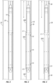
FIG. 1 illustrates a wellbore intervention tool for longitudinal and circumferential tubular slicing and cutting. -
FIG. 2 illustrates the wellbore intervention tool deployed to depth where the tubular cutting and slicing is initiated. -
FIG. 3 illustrates that the longitudinal and circumferential cuts has been completed, followed by the push-out of the cut out tubular sections. -
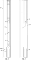
FIG. 4 illustrates that the cut out tubular sections is sliding or dropping down into the wellbore, externally of the tubular where the cut was made. -
FIG. 5 illustrates that the cut tubular sections has dropped down, and that the intervention tool can be retrieved to the surface. -
FIG. 6 illustrates the intervention tool removed, and that a section of tubular has been removed to provide access to an outer tubular. -
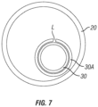
FIG. 7 illustrates a method where the tubular has one longitudinal split, where the tubular is expanded to a size large enough to be dropped or pushed over a tubular located below. -
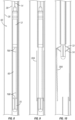
FIG. 8 shows another example embodiment of a wellbore intervention tool. -
FIG. 9 shows the example embodiment ofFIG. 8 wherein a wellbore tubular is cut. -
FIG. 10 shows the example embodiment ofFIG. 8 lifted above the cut tubular inFIG. 9 to deploy a push down module. -
FIG. 11 shows the well ofFIGS. 8 through 10 wherein cut tubular has been pushed out of the way to leave an opening in the wellbore tubular. - Chemical and explosive cutting of very short longitudinal sections, typically less than a meter both longitudinally and circumferentially, are commonly performed by a number of technologies, and have been used in the oil and gas industry for many decades. Examples of such technologies including cutting devices, some of which are described in
U.S. Patent No. 8,561,683 issued to Wood andU.S. Patent No. 5,320,174 issued to Terrell. These technologies will only provide one cut, typically to pull a tubular apart or provide a hydraulic communication path between the inside and the outside of the cut tubular. Herein are described a method and apparatus for removing a section of a wellbore tubular by longitudinal and circumferential cutting of the tubular, followed by pushing or pulling the cut sections away from the uncut tubular below and/or above the cut portion so that the cut portions are able to drop into the wellbore below a lowermost circumferential cut. A tool to perform such cutting may be designed such that the lower part of the tool protrudes below the lowest circumferential cut, and enables the tool to laterally lift the remaining, cut tubular clear of the inner wall of an externally disposed, nested tubular. -
FIG. 1 illustrates awellbore intervention tool 10 that can be deployed by a conveyance, e.g., an electric cable 14 (wireline) as shown, by a spoolable, semi-stiff rod having electrical power and signal capabilities, or by coiled tubing having an electric cable implemented. As shown inFIG. 1 , thewellbore intervention tool 10 may be deployed into atubing 30 having an external diameter of, for example, 3½ inches (89 cm). Thetubing 30 may be nested within acasing 20 having an external diameter of 9 5/8 inches (245 cm). Those skilled in the art will appreciate that the above casing and tubing dimensions are only example dimensions, and such dimensions will vary from well to well. Accordingly, such dimensions are not to be construed as a limit on the scope of the present disclosure; any other dimensions for wellbore tubulars are within the scope of the present disclosure. - The
wellbore intervention tool 10 may comprise, in its upper section, a cable head 10A or similar connector for electrical and mechanical connection to a deployment device (e.g., an armored electrical cable 14), and optionally an emergency release (associated with the cable head 10A, not shown separately). A guide nose 10B may be disposed in the lower end of thewellbore intervention tool 10. Anactuation module 12 forming part of thewellbore intervention tool 10 may comprise control circuits (not shown separately) for actuating explosive and/or chemical cutting materials and actuating one or more push-outmodules 18. - The cutting materials may be disposed, for example, in a
cutting materials module 60. The placement of the cutting materials in suchcutting materials module 60 may be chosen according to intended cut pattern of the tubular in which thewellbore intervention tool 10 is deployed. The present example embodiment contemplates a combination of cutting materials arranged on thewellbore intervention tool 10 for both longitudinal and circumferential cutting. The circumferential and longitudinal cuts may be performed simultaneously, or with a chosen time delay between them to optimize the energy created when cutting. In the example embodiment shown inFIG. 1 , two circumferentialcutter discharge ports 16B may provide that the cutting materials create longitudinally spaced apart, circumferential cuts in the tubing 30 (or other well tubular) when actuated. A longitudinalcutter discharge port 16A may enable making a longitudinal cut in thetubing 30 that extends between the circumferential cuts made through thecircumferential discharge ports 16A. Thus, when a section of a wellbore tubular (e.g., the tubing 30) is cut, at least one longitudinal cut and two circumferential cuts are made using the illustrated embodiment. Other embodiments may comprise two or more suchlongitudinal discharge ports 16A disposed at circumferentially spaced apart positions to create two or more such longitudinal cuts in the tubular. - In some embodiments, such as the embodiment shown in
FIG. 1 , thewellbore intervention tool 10 may comprise one or more push-outmodules 18. Three such modules are shown inFIG. 1 , each comprising apparatus that can extend laterally and push outward against the tubular (e.g., tubing 30) in which thewellbore intervention tool 10 is deployed. The push-outmodules 18 may comprise any mechanism to extend laterally from thewellbore intervention tool 10 and retract, for example and without limitation, hydraulic ram/cylinder combinations, motor/jack screw combinations or any similar devices. The push-outmodules 18 may be extended after deploying thewellbore intervention tool 10 to a required operating depth, orsuch modules 18 may be activated after initiating tubular cutting operations. The push-outmodules 18 may comprise rollers, wheels or similar devices on their extending elements to reduce friction between the push-outmodules 18 and the interior wall of the tubular (e.g., tubing 30). In wellbores where there is sufficient annular clearance available between nested tubulars (casing 20 and tubing 30), the push-outmodules 18 may be substituted by pull-in modules which pull cut tubular sections inward into the interior of the cut tubular, followed by release and dropping of the cut tubular sections into the tubular below the depth of thewellbore intervention tool 10. Selectively activating the various push-out or pull-in modules is possible, where for example, the lowermost push-out/pull in module(s) may be activated first followed by activation of the push-out/pull module(s) above or by activating the uppermost push-out/pull module(s) first followed by the lower push-out/pull module(s), etc. Pull-in modules may comprise electromagnets, tubular wall penetrating "spears", suction cups or similar devices that can attach to or otherwise affix to the tubular and urge such tubular toward thewellbore intervention tool 10 when the pull in module is retracted. Although the devices shown inFIG. 1 and explained above are described as "modules", it is within the scope of the present disclosure to provide apparatus capable of the above described push out and/or pull in functions in any form that can be conveyed with thewellbore intervention tool 10, whether or not such apparatus is in modular in form. - In the present example embodiment, the push-out module(s) 18 when actuated may spread the tubular (e.g., tubing 30) along the longitudinal cuts after the cutting materials are actuated. A wellbore intervention tool as shown in
FIG. 1 may be used as further explained below. - In the present example embodiment, the push out module(s) 18 may be disposed longitudinally along the
wellbore intervention tool 10 between the spaced apartcircumferential discharge ports 16B. - Other embodiments may omit the push-out and/or pull in modules entirely, having only the cutting
materials module 60. In such embodiments, the functions performed by the push our or pull in modules may be performed by a separate wellbore intervention tool. - Some embodiments of the wellbore intervention tool may comprise only one
circumferential discharge port 16B. Such embodiments may be used, among other purposes, to sever additional segments of wellbore tubular as will be further explained below. - The present example embodiment may comprise a
guide 22 on the longitudinal end opposite the end connected to thecable 14. Theguide 22 may comprise one ormore rollers 22A to reduce friction when thewellbore intervention tool 10 is moved along the interior of a wellbore tubular. -
FIG. 2 illustrates thewellbore intervention tool 10 deployed to a chosen depth where tubular cutting is to be performed. -
FIG. 3 illustrates that longitudinal and circumferential cuts, C1, C2, respectively have been completed by actuating the cutting materials in the cuttingmaterial module 60, followed by operation (in this case) extension of the push-outmodules 18. Extension of the push-outmodules 18 after cutting the tubular (e.g., tubing 30) will result in the cut-outsection 30A being radially expanded toward the surroundingcasing 20, while thetubing 30 above and below the cuts C1, C2 will be laterally moved (lifted in an inclined well) away from thecasing 20. Such movement will allow thecut tubing section 30A to be dropped outside the upper end of the remaininguncut tubing 30C, located below the cut section (i.e., below cut C2 inFIG. 3 ). Because no wellbore is perfectly vertical, a tubing string will generally rest against the interior wall of the surrounding casing where no tubing centralizer or other annular element (in annular space A) is present. If the part of the tubing collocated with the wellbore intervention tool inside was not lifted away from the casing, one or several of the cut-out sections would not be able drop down outside the tubing string below the cut C2 and into the annular space A. -
FIG. 4 illustrates that the cut outtubular section 30A is sliding or dropping down into the well, external to thetubing 30 below where the lower circumferential cut C2 was made, and thus into the annular space A. -
FIG. 5 illustrates that thecut tubular section 30A has dropped down, the push-outmodules 18 have been retracted, and that thewellbore intervention tool 10 can be retrieved to the surface, e.g., by retracting the cable (14 inFIG. 1 ). -
FIG. 6 illustrates thewellbore intervention tool 10 has been removed from thetubing 30, and that a section of well tubular (tubing 30) has been removed so that access along apath 50 to the interior of the outer tubular (casing 20) is provided for logging instruments and other required intervention tools. In some embodiments, following cutting the wellbore tubular as explained herein, at least one wellbore intervention operation may be conducted in the annular space A through thepath 50. Such operation may comprise, e.g., wireline logging, among other operations. -
FIG. 7 illustrates an example embodiment of a method where the tubular has only one longitudinal cut L, where the cut section oftubular 30A is radially expanded to a size large enough to be dropped or pushed over the cut tubular (e.g., tubing 30) located below the lower circumferential cut (C2 inFIG. 3 ). - The above operations may be repeated any number of times, so that required lengths of tubulars are removed. One tubular section may be of a length of, for example, 10-12 meters, while there may be requirements to remove up to 100 meters of tubular. A tool as herein described may also be configured for longer than 10-12 meter cuts, e.g., by increasing the longitudinal spacing between the circumferential discharge ports (16A in
FIG. 1 ). -
FIG. 8 shows another example embodiment of thewellbore intervention tool 10. The present example embodiment of thewellbore intervention tool 10 may be similarly configured as the embodiment explained with reference toFIG. 1 but with the following differences. The present example embodiment of thewellbore intervention tool 10 may comprise, instead of the guide (22 inFIG. 1 ) at one longitudinal end, a push downmodule 70. The push downmodule 70 may comprise components, to be explained further below, that engage the top of a severed wellbore tubular to enable the wellbore intervention tool to apply axial force to the severed section in order to move it away from the remainder of the wellbore tubular. The present example embodiment may omit the one or more push out (or pull in) modules explained above (18 inFIG. 1 -
FIG. 9 shows the example embodiment ofFIG. 8 wherein a wellbore tubular is cut. In this case, the cut tubular istubing 30, as in the previously explained embodiments. Actuation of the cutting materials in thecuttings material module 60 may make two or more longitudinally spaced apart circumferential cuts in the tubing 30 (or any other wellbore tubular to be severed). Shock wave from detonating the cutting materials may expand the severedsection 30A of the wellbore tubular 30 radially so that it is larger in expanded diameter than the outer diameter of the remainder of the wellbore tubular. -
FIG. 10 shows the example embodiment ofFIG. 8 lifted above the severed tubular 30A inFIG. 9 to deploy the push downmodule 70. The push downmodule 70 may comprise one ormore arms 72 pivotally coupled to thewellbore intervention tool 10. Eacharm 72 may be urged to radially extend from thewellbore intervention tool 10 by a biasing device 74 such as a spring or hydraulic cylinder. When thewellbore intervention tool 10 is axially moved above the severed tubular 30A, the arm(s) 72 extend radially as shown inFIG. 10 to enable engagement of the extended arm(s) 72 with the top of the severed tubular 30A. Thewellbore intervention tool 10 may then be moved downward in the well to urge the severed tubular 30A downward in the annular space A.). Although the push downmodule 60 is shown proximate the lower end of thewellbore intervention tool 10, for purposes of defining the scope of the present disclosure, it is only necessary that the push downmodule 60 be located so that thearm 72 remains compressed until which time it is desired to radially expand thearm 72 to enable push down of the severed wellbore tubular. For example, in a wellbore intervention tool such as shown inFIG. 8 , the push downmodule 60 could be located axially proximate theactuator module 12. Thus, severing the wellbore tubular would not immediately result in radial expansion of thearm 72. By moving such embodiment of the wellbore intervention tool downward below the position at which the upper circumferential cut is made, thearm 72 will expand radially such that it engages the top of the severedsection 30A of the wellbore tubular. -
FIG. 11 shows the well ofFIGS. 8 through 10 wherein thecut tubular 30A has been pushed out of the way to leave anopening 31 in thewellbore tubular 30. Theopening 31 may provide access to the interior wall of the tubular, e.g., thecasing 20, in which the wellbore tubular 30 is nested for subsequent intervention operations such as logging or perforating. - In the present example embodiments, the severed tubular may be deformed or pushed outward into the
annular space 50 by energy from operation of the cutting materials. Such outward pushing may enable severed segments of the tubular (e.g., tubing 30) to drop below theupper end 30D inFIG. 11 of the lower part of the severed tubular, either by gravity alone or using the push down module as explained with reference toFIGS, 8 through 10 . - In some embodiments, and as explained with reference to
FIG. 1 , may comprise only onecircumferential discharge port 16B. Such embodiments may be configured as explained with reference toFIG. 1 orFIG. 8 . Such embodiments may be used to sever additional segments of tubular, for example, by making one or more longitudinal cuts in the tubular from the bottom 30C of the several tubular 30 extending upwardly, or from the top 30D of the severed tubular extending downwardly. Such longitudinal cut(s) may be accompanied by a circumferential cut proximate the longitudinal end of the longitudinal cut(s) to sever an additional segment of the tubular 30. The foregoing procedure may be repeated until a chosen length of the tubular 30 is severed and displaced. - Although only a few examples have been described in detail above, those skilled in the art will readily appreciate that many modifications are possible in the examples. Accordingly, all such modifications are intended to be included within the scope of this disclosure as defined in the following claims.
Claims (10)
- An apparatus for cutting sections of a wellbore tubular, comprising:a housing shaped to enable movement along an interior of the wellbore tubular, the housing having an upper end arranged to connect to a conveyance and a lower end comprising a guide;cutting materials disposed in the housing and arranged to cut the wellbore tubular in two, longitudinally spaced apart circumferential cuts and at least one longitudinal cut extending between the circumferential cuts, wherein the cutting materials are arranged to create the circumferential cuts and the at least one longitudinal cut simultaneously; andat least one of a push-out module and a push in module disposed between the upper end and the guide and arranged to contact the tubular to at least one of radially expand the tubular and radially contract the tubular.
- The apparatus of claim 1 wherein the cutting materials comprise explosive cutters.
- The apparatus of claim 1 wherein the cutting materials comprise chemical cutters.
- The apparatus of claim 1 wherein the at least one push out module comprises a hydraulic ram/cylinder combination.
- The apparatus of claim 1 further comprising a plurality of longitudinally spaced apart push out modules.
- The apparatus of claim 1 wherein the cutting materials are arranged to cut the wellbore tubular along a plurality of longitudinal cuts extending between the circumferential cuts.
- A method for cutting a wellbore tubular, comprising:positioning a tool in the wellbore tubular at a selected depth, the tool comprising a housing shaped to enable movement along an interior of the wellbore tubular, the housing having an upper end arranged to connect to a conveyance and a lower end comprising a guide; cutting materials disposed in the housing and arranged to cut the wellbore tubular in two, longitudinally spaced apart circumferential cuts and at least one longitudinal cut extending between the longitudinally spaced apart circumferential cuts;actuating the cutting materials, wherein the cutting materials are actuated to create the circumferential cuts and the at least one longitudinal cut simultaneously; andactuating at least one of a push-out module or a pull in module to radially expand or contract the cut wellbore tubular to enable dropping a cut section over the wellbore tubular below the lower circumferential cut.
- The method of claim 7 further comprising actuating the cutting materials to create a plurality of longitudinal cuts in the wellbore tubular.
- The method of claim 7 wherein the at least one of a push-out module and a pull in module is operated with sufficient force to laterally lift the tubular from a wall of a conduit in which the tubular is nested.
- The method of claim 7 further comprising conducting at least one well intervention operation through an opening created by cutting the wellbore tubular.
Applications Claiming Priority (2)
| Application Number | Priority Date | Filing Date | Title |
|---|---|---|---|
| US201962819824P | 2019-03-18 | 2019-03-18 | |
| PCT/IB2020/052426 WO2020188481A1 (en) | 2019-03-18 | 2020-03-17 | Method to longitudinally and circumferential cut out and remove a section of a wellbore tubular |
Publications (2)
| Publication Number | Publication Date |
|---|---|
| EP3942144A1 EP3942144A1 (en) | 2022-01-26 |
| EP3942144B1 true EP3942144B1 (en) | 2024-09-18 |
Family
ID=70416453
Family Applications (1)
| Application Number | Title | Priority Date | Filing Date |
|---|---|---|---|
| EP20720929.7A Active EP3942144B1 (en) | 2019-03-18 | 2020-03-17 | Method to longitudinally and circumferential cut out and remove a section of a wellbore tubular |
Country Status (5)
| Country | Link |
|---|---|
| US (1) | US11885190B2 (en) |
| EP (1) | EP3942144B1 (en) |
| AU (1) | AU2020243600B2 (en) |
| MY (1) | MY209705A (en) |
| WO (1) | WO2020188481A1 (en) |
Families Citing this family (2)
| Publication number | Priority date | Publication date | Assignee | Title |
|---|---|---|---|---|
| US11725458B2 (en) * | 2021-10-01 | 2023-08-15 | Saudi Arabian Oil Company | Cutting a sidetrack window |
| GB202409116D0 (en) * | 2024-06-25 | 2024-08-07 | Swiftwell Ltd | Apparatus and a method of removing a section of conduit from a wellbore through tubing |
Citations (2)
| Publication number | Priority date | Publication date | Assignee | Title |
|---|---|---|---|---|
| WO2014117846A1 (en) * | 2013-01-31 | 2014-08-07 | Statoil Petroleum As | A method of plugging a well |
| US20150233218A1 (en) * | 2014-02-18 | 2015-08-20 | Well Technology As | Hydraulic Cutting Tool, System and Method for Controlled Hydraulic Cutting Through a Pipe Wall in a Well |
Family Cites Families (12)
| Publication number | Priority date | Publication date | Assignee | Title |
|---|---|---|---|---|
| US3750748A (en) * | 1971-12-27 | 1973-08-07 | J Kinley | Liner separation apparatus |
| US5320174A (en) | 1992-06-16 | 1994-06-14 | Terrell Donna K | Downhole chemical cutting tool and process |
| US5765756A (en) * | 1994-09-30 | 1998-06-16 | Tiw Corporation | Abrasive slurry jetting tool and method |
| US5575331A (en) * | 1995-06-07 | 1996-11-19 | Halliburton Company | Chemical cutter |
| US7540327B2 (en) * | 2006-04-28 | 2009-06-02 | Schlumberger Technology Corporation | Abrasive jet cutting system and method for cutting wellbore tubulars |
| US9089928B2 (en) * | 2008-08-20 | 2015-07-28 | Foro Energy, Inc. | Laser systems and methods for the removal of structures |
| US8561683B2 (en) | 2010-09-22 | 2013-10-22 | Owen Oil Tools, Lp | Wellbore tubular cutter |
| US9359848B2 (en) * | 2013-06-04 | 2016-06-07 | Halliburton Energy Services, Inc. | Systems and methods for removing a section of casing |
| WO2015163872A1 (en) * | 2014-04-23 | 2015-10-29 | Halliburton Energy Services, Inc. | Jet cutter having a truncated liner at apex |
| US10370919B2 (en) * | 2014-05-16 | 2019-08-06 | Aarbakke Innovation As | Multifunction wellbore tubular penetration tool |
| US9428979B2 (en) * | 2014-05-29 | 2016-08-30 | William T. Bell | Shaped charge casing cutter |
| WO2020139336A1 (en) * | 2018-12-27 | 2020-07-02 | Halliburton Energy Services, Inc. | Insensitive high explosive based tubing cutter |
-
2020
- 2020-03-17 EP EP20720929.7A patent/EP3942144B1/en active Active
- 2020-03-17 AU AU2020243600A patent/AU2020243600B2/en active Active
- 2020-03-17 WO PCT/IB2020/052426 patent/WO2020188481A1/en not_active Ceased
- 2020-03-17 MY MYPI2021005397A patent/MY209705A/en unknown
-
2021
- 2021-09-17 US US17/478,459 patent/US11885190B2/en active Active
Patent Citations (2)
| Publication number | Priority date | Publication date | Assignee | Title |
|---|---|---|---|---|
| WO2014117846A1 (en) * | 2013-01-31 | 2014-08-07 | Statoil Petroleum As | A method of plugging a well |
| US20150233218A1 (en) * | 2014-02-18 | 2015-08-20 | Well Technology As | Hydraulic Cutting Tool, System and Method for Controlled Hydraulic Cutting Through a Pipe Wall in a Well |
Also Published As
| Publication number | Publication date |
|---|---|
| EP3942144A1 (en) | 2022-01-26 |
| AU2020243600A1 (en) | 2021-10-07 |
| WO2020188481A1 (en) | 2020-09-24 |
| US11885190B2 (en) | 2024-01-30 |
| BR112021018402A2 (en) | 2021-11-30 |
| MY209705A (en) | 2025-07-30 |
| AU2020243600B2 (en) | 2023-09-07 |
| CA3131092A1 (en) | 2020-09-24 |
| US20220074279A1 (en) | 2022-03-10 |
Similar Documents
| Publication | Publication Date | Title |
|---|---|---|
| EP3779118B1 (en) | Method of removing a downhole casing | |
| US10287860B2 (en) | Downhole mechanical tubing perforator | |
| US20130306316A1 (en) | Separable completion architecture | |
| CA3008605C (en) | Mills with shearable cutting members for milling casings in wellbores | |
| US10208572B2 (en) | Apparatus and method for perforating a subterranean formation | |
| US11885190B2 (en) | Apparatus and method to longitudinally and circumferentially cut and remove a section of a wellbore tubular | |
| US10060233B2 (en) | Hydraulic tubing perforator | |
| US9051817B2 (en) | Pipe conveyed extendable well logging tool with protector | |
| US6848507B2 (en) | Expandable wirefinder and method for use of same | |
| US20150300135A1 (en) | Reduced outer diameter expandable perforator | |
| CA3131092C (en) | Method to longitudinally and circumferential cut out and remove a section of a wellbore tubular | |
| WO2020006187A1 (en) | Casing conveyed, externally mounted perforation concept | |
| CA3025293C (en) | Expandable junk mill | |
| BR112021018402B1 (en) | APPARATUS FOR CUTTING SECTIONS OF A WELLHOLE TUBE, AND METHOD FOR CUTTING A WELLHOLE TUBE | |
| EP3929398B1 (en) | Method for separating nested well tubulars in gravity contact with each other | |
| RU2781432C1 (en) | Hoisting tool and method for extracting a downhole tool | |
| US11613949B2 (en) | Apparatus for performing multiple downhole operations in a production tubing tubular | |
| WO2020006268A1 (en) | Casing conveyed, externally mounted perforation concept |
Legal Events
| Date | Code | Title | Description |
|---|---|---|---|
| STAA | Information on the status of an ep patent application or granted ep patent |
Free format text: STATUS: UNKNOWN |
|
| STAA | Information on the status of an ep patent application or granted ep patent |
Free format text: STATUS: THE INTERNATIONAL PUBLICATION HAS BEEN MADE |
|
| PUAI | Public reference made under article 153(3) epc to a published international application that has entered the european phase |
Free format text: ORIGINAL CODE: 0009012 |
|
| STAA | Information on the status of an ep patent application or granted ep patent |
Free format text: STATUS: REQUEST FOR EXAMINATION WAS MADE |
|
| 17P | Request for examination filed |
Effective date: 20211014 |
|
| AK | Designated contracting states |
Kind code of ref document: A1 Designated state(s): AL AT BE BG CH CY CZ DE DK EE ES FI FR GB GR HR HU IE IS IT LI LT LU LV MC MK MT NL NO PL PT RO RS SE SI SK SM TR |
|
| DAV | Request for validation of the european patent (deleted) | ||
| DAX | Request for extension of the european patent (deleted) | ||
| STAA | Information on the status of an ep patent application or granted ep patent |
Free format text: STATUS: EXAMINATION IS IN PROGRESS |
|
| 17Q | First examination report despatched |
Effective date: 20221213 |
|
| GRAP | Despatch of communication of intention to grant a patent |
Free format text: ORIGINAL CODE: EPIDOSNIGR1 |
|
| STAA | Information on the status of an ep patent application or granted ep patent |
Free format text: STATUS: GRANT OF PATENT IS INTENDED |
|
| INTG | Intention to grant announced |
Effective date: 20240411 |
|
| GRAS | Grant fee paid |
Free format text: ORIGINAL CODE: EPIDOSNIGR3 |
|
| GRAA | (expected) grant |
Free format text: ORIGINAL CODE: 0009210 |
|
| STAA | Information on the status of an ep patent application or granted ep patent |
Free format text: STATUS: THE PATENT HAS BEEN GRANTED |
|
| AK | Designated contracting states |
Kind code of ref document: B1 Designated state(s): AL AT BE BG CH CY CZ DE DK EE ES FI FR GB GR HR HU IE IS IT LI LT LU LV MC MK MT NL NO PL PT RO RS SE SI SK SM TR |
|
| REG | Reference to a national code |
Ref country code: GB Ref legal event code: FG4D |
|
| REG | Reference to a national code |
Ref country code: CH Ref legal event code: EP |
|
| REG | Reference to a national code |
Ref country code: DE Ref legal event code: R096 Ref document number: 602020037900 Country of ref document: DE |
|
| REG | Reference to a national code |
Ref country code: IE Ref legal event code: FG4D |
|
| P01 | Opt-out of the competence of the unified patent court (upc) registered |
Free format text: CASE NUMBER: APP_52718/2024 Effective date: 20240919 |
|
| REG | Reference to a national code |
Ref country code: LT Ref legal event code: MG9D |
|
| PG25 | Lapsed in a contracting state [announced via postgrant information from national office to epo] |
Ref country code: NO Free format text: LAPSE BECAUSE OF FAILURE TO SUBMIT A TRANSLATION OF THE DESCRIPTION OR TO PAY THE FEE WITHIN THE PRESCRIBED TIME-LIMIT Effective date: 20241218 |
|
| PG25 | Lapsed in a contracting state [announced via postgrant information from national office to epo] |
Ref country code: GR Free format text: LAPSE BECAUSE OF FAILURE TO SUBMIT A TRANSLATION OF THE DESCRIPTION OR TO PAY THE FEE WITHIN THE PRESCRIBED TIME-LIMIT Effective date: 20241219 Ref country code: FI Free format text: LAPSE BECAUSE OF FAILURE TO SUBMIT A TRANSLATION OF THE DESCRIPTION OR TO PAY THE FEE WITHIN THE PRESCRIBED TIME-LIMIT Effective date: 20240918 |
|
| PG25 | Lapsed in a contracting state [announced via postgrant information from national office to epo] |
Ref country code: BG Free format text: LAPSE BECAUSE OF FAILURE TO SUBMIT A TRANSLATION OF THE DESCRIPTION OR TO PAY THE FEE WITHIN THE PRESCRIBED TIME-LIMIT Effective date: 20240918 |
|
| PG25 | Lapsed in a contracting state [announced via postgrant information from national office to epo] |
Ref country code: LV Free format text: LAPSE BECAUSE OF FAILURE TO SUBMIT A TRANSLATION OF THE DESCRIPTION OR TO PAY THE FEE WITHIN THE PRESCRIBED TIME-LIMIT Effective date: 20240918 |
|
| PG25 | Lapsed in a contracting state [announced via postgrant information from national office to epo] |
Ref country code: HR Free format text: LAPSE BECAUSE OF FAILURE TO SUBMIT A TRANSLATION OF THE DESCRIPTION OR TO PAY THE FEE WITHIN THE PRESCRIBED TIME-LIMIT Effective date: 20240918 |
|
| REG | Reference to a national code |
Ref country code: NL Ref legal event code: MP Effective date: 20240918 |
|
| PG25 | Lapsed in a contracting state [announced via postgrant information from national office to epo] |
Ref country code: RS Free format text: LAPSE BECAUSE OF FAILURE TO SUBMIT A TRANSLATION OF THE DESCRIPTION OR TO PAY THE FEE WITHIN THE PRESCRIBED TIME-LIMIT Effective date: 20241218 |
|
| PG25 | Lapsed in a contracting state [announced via postgrant information from national office to epo] |
Ref country code: RS Free format text: LAPSE BECAUSE OF FAILURE TO SUBMIT A TRANSLATION OF THE DESCRIPTION OR TO PAY THE FEE WITHIN THE PRESCRIBED TIME-LIMIT Effective date: 20241218 Ref country code: NO Free format text: LAPSE BECAUSE OF FAILURE TO SUBMIT A TRANSLATION OF THE DESCRIPTION OR TO PAY THE FEE WITHIN THE PRESCRIBED TIME-LIMIT Effective date: 20241218 Ref country code: LV Free format text: LAPSE BECAUSE OF FAILURE TO SUBMIT A TRANSLATION OF THE DESCRIPTION OR TO PAY THE FEE WITHIN THE PRESCRIBED TIME-LIMIT Effective date: 20240918 Ref country code: HR Free format text: LAPSE BECAUSE OF FAILURE TO SUBMIT A TRANSLATION OF THE DESCRIPTION OR TO PAY THE FEE WITHIN THE PRESCRIBED TIME-LIMIT Effective date: 20240918 Ref country code: GR Free format text: LAPSE BECAUSE OF FAILURE TO SUBMIT A TRANSLATION OF THE DESCRIPTION OR TO PAY THE FEE WITHIN THE PRESCRIBED TIME-LIMIT Effective date: 20241219 Ref country code: FI Free format text: LAPSE BECAUSE OF FAILURE TO SUBMIT A TRANSLATION OF THE DESCRIPTION OR TO PAY THE FEE WITHIN THE PRESCRIBED TIME-LIMIT Effective date: 20240918 Ref country code: BG Free format text: LAPSE BECAUSE OF FAILURE TO SUBMIT A TRANSLATION OF THE DESCRIPTION OR TO PAY THE FEE WITHIN THE PRESCRIBED TIME-LIMIT Effective date: 20240918 |
|
| REG | Reference to a national code |
Ref country code: AT Ref legal event code: MK05 Ref document number: 1724829 Country of ref document: AT Kind code of ref document: T Effective date: 20240918 |
|
| PG25 | Lapsed in a contracting state [announced via postgrant information from national office to epo] |
Ref country code: NL Free format text: LAPSE BECAUSE OF FAILURE TO SUBMIT A TRANSLATION OF THE DESCRIPTION OR TO PAY THE FEE WITHIN THE PRESCRIBED TIME-LIMIT Effective date: 20240918 |
|
| PG25 | Lapsed in a contracting state [announced via postgrant information from national office to epo] |
Ref country code: PT Free format text: LAPSE BECAUSE OF FAILURE TO SUBMIT A TRANSLATION OF THE DESCRIPTION OR TO PAY THE FEE WITHIN THE PRESCRIBED TIME-LIMIT Effective date: 20250120 Ref country code: IS Free format text: LAPSE BECAUSE OF FAILURE TO SUBMIT A TRANSLATION OF THE DESCRIPTION OR TO PAY THE FEE WITHIN THE PRESCRIBED TIME-LIMIT Effective date: 20250118 |
|
| PG25 | Lapsed in a contracting state [announced via postgrant information from national office to epo] |
Ref country code: RO Free format text: LAPSE BECAUSE OF FAILURE TO SUBMIT A TRANSLATION OF THE DESCRIPTION OR TO PAY THE FEE WITHIN THE PRESCRIBED TIME-LIMIT Effective date: 20240918 Ref country code: SM Free format text: LAPSE BECAUSE OF FAILURE TO SUBMIT A TRANSLATION OF THE DESCRIPTION OR TO PAY THE FEE WITHIN THE PRESCRIBED TIME-LIMIT Effective date: 20240918 |
|
| PG25 | Lapsed in a contracting state [announced via postgrant information from national office to epo] |
Ref country code: ES Free format text: LAPSE BECAUSE OF FAILURE TO SUBMIT A TRANSLATION OF THE DESCRIPTION OR TO PAY THE FEE WITHIN THE PRESCRIBED TIME-LIMIT Effective date: 20240918 |
|
| PG25 | Lapsed in a contracting state [announced via postgrant information from national office to epo] |
Ref country code: EE Free format text: LAPSE BECAUSE OF FAILURE TO SUBMIT A TRANSLATION OF THE DESCRIPTION OR TO PAY THE FEE WITHIN THE PRESCRIBED TIME-LIMIT Effective date: 20240918 Ref country code: AT Free format text: LAPSE BECAUSE OF FAILURE TO SUBMIT A TRANSLATION OF THE DESCRIPTION OR TO PAY THE FEE WITHIN THE PRESCRIBED TIME-LIMIT Effective date: 20240918 |
|
| PG25 | Lapsed in a contracting state [announced via postgrant information from national office to epo] |
Ref country code: CZ Free format text: LAPSE BECAUSE OF FAILURE TO SUBMIT A TRANSLATION OF THE DESCRIPTION OR TO PAY THE FEE WITHIN THE PRESCRIBED TIME-LIMIT Effective date: 20240918 Ref country code: PL Free format text: LAPSE BECAUSE OF FAILURE TO SUBMIT A TRANSLATION OF THE DESCRIPTION OR TO PAY THE FEE WITHIN THE PRESCRIBED TIME-LIMIT Effective date: 20240918 |
|
| PG25 | Lapsed in a contracting state [announced via postgrant information from national office to epo] |
Ref country code: IT Free format text: LAPSE BECAUSE OF FAILURE TO SUBMIT A TRANSLATION OF THE DESCRIPTION OR TO PAY THE FEE WITHIN THE PRESCRIBED TIME-LIMIT Effective date: 20240918 Ref country code: SK Free format text: LAPSE BECAUSE OF FAILURE TO SUBMIT A TRANSLATION OF THE DESCRIPTION OR TO PAY THE FEE WITHIN THE PRESCRIBED TIME-LIMIT Effective date: 20240918 |
|
| REG | Reference to a national code |
Ref country code: DE Ref legal event code: R097 Ref document number: 602020037900 Country of ref document: DE |
|
| PG25 | Lapsed in a contracting state [announced via postgrant information from national office to epo] |
Ref country code: DK Free format text: LAPSE BECAUSE OF FAILURE TO SUBMIT A TRANSLATION OF THE DESCRIPTION OR TO PAY THE FEE WITHIN THE PRESCRIBED TIME-LIMIT Effective date: 20240918 |
|
| PLBE | No opposition filed within time limit |
Free format text: ORIGINAL CODE: 0009261 |
|
| STAA | Information on the status of an ep patent application or granted ep patent |
Free format text: STATUS: NO OPPOSITION FILED WITHIN TIME LIMIT |
|
| 26N | No opposition filed |
Effective date: 20250619 |
|
| PG25 | Lapsed in a contracting state [announced via postgrant information from national office to epo] |
Ref country code: SE Free format text: LAPSE BECAUSE OF FAILURE TO SUBMIT A TRANSLATION OF THE DESCRIPTION OR TO PAY THE FEE WITHIN THE PRESCRIBED TIME-LIMIT Effective date: 20240918 |
|
| REG | Reference to a national code |
Ref country code: DE Ref legal event code: R119 Ref document number: 602020037900 Country of ref document: DE |
|
| PG25 | Lapsed in a contracting state [announced via postgrant information from national office to epo] |
Ref country code: MC Free format text: LAPSE BECAUSE OF FAILURE TO SUBMIT A TRANSLATION OF THE DESCRIPTION OR TO PAY THE FEE WITHIN THE PRESCRIBED TIME-LIMIT Effective date: 20240918 |
|
| REG | Reference to a national code |
Ref country code: CH Ref legal event code: H13 Free format text: ST27 STATUS EVENT CODE: U-0-0-H10-H13 (AS PROVIDED BY THE NATIONAL OFFICE) Effective date: 20251024 |
|
| PG25 | Lapsed in a contracting state [announced via postgrant information from national office to epo] |
Ref country code: LU Free format text: LAPSE BECAUSE OF NON-PAYMENT OF DUE FEES Effective date: 20250317 |
|
| REG | Reference to a national code |
Ref country code: BE Ref legal event code: MM Effective date: 20250331 |
|
| PG25 | Lapsed in a contracting state [announced via postgrant information from national office to epo] |
Ref country code: DE Free format text: LAPSE BECAUSE OF NON-PAYMENT OF DUE FEES Effective date: 20251001 |
|
| PG25 | Lapsed in a contracting state [announced via postgrant information from national office to epo] |
Ref country code: FR Free format text: LAPSE BECAUSE OF NON-PAYMENT OF DUE FEES Effective date: 20250331 |
|
| PG25 | Lapsed in a contracting state [announced via postgrant information from national office to epo] |
Ref country code: BE Free format text: LAPSE BECAUSE OF NON-PAYMENT OF DUE FEES Effective date: 20250331 |
|
| PG25 | Lapsed in a contracting state [announced via postgrant information from national office to epo] |
Ref country code: CH Free format text: LAPSE BECAUSE OF NON-PAYMENT OF DUE FEES Effective date: 20250331 |
|
| PG25 | Lapsed in a contracting state [announced via postgrant information from national office to epo] |
Ref country code: IE Free format text: LAPSE BECAUSE OF NON-PAYMENT OF DUE FEES Effective date: 20250317 |
|
| PGFP | Annual fee paid to national office [announced via postgrant information from national office to epo] |
Ref country code: GB Payment date: 20260310 Year of fee payment: 7 |