EP3941088A1 - Waterproof microphone - Google Patents
Waterproof microphone Download PDFInfo
- Publication number
- EP3941088A1 EP3941088A1 EP21184991.4A EP21184991A EP3941088A1 EP 3941088 A1 EP3941088 A1 EP 3941088A1 EP 21184991 A EP21184991 A EP 21184991A EP 3941088 A1 EP3941088 A1 EP 3941088A1
- Authority
- EP
- European Patent Office
- Prior art keywords
- rear chamber
- waterproof
- sealing member
- hole
- chamber
- Prior art date
- Legal status (The legal status is an assumption and is not a legal conclusion. Google has not performed a legal analysis and makes no representation as to the accuracy of the status listed.)
- Granted
Links
Images



Classifications
-
- H—ELECTRICITY
- H04—ELECTRIC COMMUNICATION TECHNIQUE
- H04R—LOUDSPEAKERS, MICROPHONES, GRAMOPHONE PICK-UPS OR LIKE ACOUSTIC ELECTROMECHANICAL TRANSDUCERS; ELECTRIC HEARING AIDS; PUBLIC ADDRESS SYSTEMS
- H04R1/00—Details of transducers, loudspeakers or microphones
- H04R1/08—Mouthpieces; Microphones; Attachments therefor
- H04R1/083—Special constructions of mouthpieces
-
- H—ELECTRICITY
- H04—ELECTRIC COMMUNICATION TECHNIQUE
- H04R—LOUDSPEAKERS, MICROPHONES, GRAMOPHONE PICK-UPS OR LIKE ACOUSTIC ELECTROMECHANICAL TRANSDUCERS; ELECTRIC HEARING AIDS; PUBLIC ADDRESS SYSTEMS
- H04R1/00—Details of transducers, loudspeakers or microphones
- H04R1/08—Mouthpieces; Microphones; Attachments therefor
- H04R1/083—Special constructions of mouthpieces
- H04R1/086—Protective screens, e.g. all weather or wind screens
-
- H—ELECTRICITY
- H04—ELECTRIC COMMUNICATION TECHNIQUE
- H04R—LOUDSPEAKERS, MICROPHONES, GRAMOPHONE PICK-UPS OR LIKE ACOUSTIC ELECTROMECHANICAL TRANSDUCERS; ELECTRIC HEARING AIDS; PUBLIC ADDRESS SYSTEMS
- H04R9/00—Transducers of moving-coil, moving-strip, or moving-wire type
- H04R9/08—Microphones
-
- H—ELECTRICITY
- H04—ELECTRIC COMMUNICATION TECHNIQUE
- H04R—LOUDSPEAKERS, MICROPHONES, GRAMOPHONE PICK-UPS OR LIKE ACOUSTIC ELECTROMECHANICAL TRANSDUCERS; ELECTRIC HEARING AIDS; PUBLIC ADDRESS SYSTEMS
- H04R1/00—Details of transducers, loudspeakers or microphones
- H04R1/02—Casings; Cabinets ; Supports therefor; Mountings therein
-
- H—ELECTRICITY
- H04—ELECTRIC COMMUNICATION TECHNIQUE
- H04R—LOUDSPEAKERS, MICROPHONES, GRAMOPHONE PICK-UPS OR LIKE ACOUSTIC ELECTROMECHANICAL TRANSDUCERS; ELECTRIC HEARING AIDS; PUBLIC ADDRESS SYSTEMS
- H04R1/00—Details of transducers, loudspeakers or microphones
- H04R1/20—Arrangements for obtaining desired frequency or directional characteristics
- H04R1/22—Arrangements for obtaining desired frequency or directional characteristics for obtaining desired frequency characteristic only
- H04R1/222—Arrangements for obtaining desired frequency or directional characteristics for obtaining desired frequency characteristic only for microphones
-
- H—ELECTRICITY
- H04—ELECTRIC COMMUNICATION TECHNIQUE
- H04R—LOUDSPEAKERS, MICROPHONES, GRAMOPHONE PICK-UPS OR LIKE ACOUSTIC ELECTROMECHANICAL TRANSDUCERS; ELECTRIC HEARING AIDS; PUBLIC ADDRESS SYSTEMS
- H04R1/00—Details of transducers, loudspeakers or microphones
- H04R1/20—Arrangements for obtaining desired frequency or directional characteristics
- H04R1/22—Arrangements for obtaining desired frequency or directional characteristics for obtaining desired frequency characteristic only
- H04R1/28—Transducer mountings or enclosures modified by provision of mechanical or acoustic impedances, e.g. resonator, damping means
- H04R1/2807—Enclosures comprising vibrating or resonating arrangements
- H04R1/283—Enclosures comprising vibrating or resonating arrangements using a passive diaphragm
-
- H—ELECTRICITY
- H04—ELECTRIC COMMUNICATION TECHNIQUE
- H04R—LOUDSPEAKERS, MICROPHONES, GRAMOPHONE PICK-UPS OR LIKE ACOUSTIC ELECTROMECHANICAL TRANSDUCERS; ELECTRIC HEARING AIDS; PUBLIC ADDRESS SYSTEMS
- H04R9/00—Transducers of moving-coil, moving-strip, or moving-wire type
- H04R9/02—Details
-
- H—ELECTRICITY
- H04—ELECTRIC COMMUNICATION TECHNIQUE
- H04R—LOUDSPEAKERS, MICROPHONES, GRAMOPHONE PICK-UPS OR LIKE ACOUSTIC ELECTROMECHANICAL TRANSDUCERS; ELECTRIC HEARING AIDS; PUBLIC ADDRESS SYSTEMS
- H04R1/00—Details of transducers, loudspeakers or microphones
- H04R1/44—Special adaptations for subaqueous use, e.g. for hydrophone
Definitions
- the present invention relates to a waterproof microphone.
- Patent Literature 1 Japanese Patent Publication No. S53-039766 (referred to as Patent Literature 1, hereinafter) is an example of a conventional technique of a drip-proof structure for an audio component storage box.
- Patent Literature 1 realizes a complete watertight, airtight structure for a room inside a case by fixing a waterproof vibrating diaphragm of a speaker and waterproof packing in such a manner as to cover a sound emission hole (Patent Literature 1).
- the problem pertaining to this conventional waterproof microphone is either insufficient waterproofing property and durability due to an attempt to ensure sufficient acoustic characteristics, or insufficient acoustic characteristics due to an attempt to ensure sufficient waterproofing property and durability.
- An object of the present invention is to provide a waterproof microphone capable of achieving both acoustic characteristics and waterproofing property/durability.
- a waterproof microphone according to the present invention includes a case, a waterproof vibrating membrane, a microphone unit, and a sealing member.
- the case includes a partition wall that separates an internal space into two chambers, a front chamber and a rear chamber.
- the partition wall includes a hole that allows communication between the front chamber and the rear chamber.
- Surfaces of the front chamber and the rear chamber that face the partition wall each include an opening portion.
- the waterproof vibrating membrane covers the opening portion of the front chamber.
- the microphone unit is attached to a surface of the partition wall on the rear chamber side.
- the sealing member seals the opening portion of the rear chamber and includes an air hole that allows communication between the rear chamber and an external space.
- the waterproof microphone of the present invention is capable of achieving both acoustic characteristics and waterproofing property/durability.
- a waterproof microphone 1 of the present example includes a case 11, a waterproof vibrating membrane 12, a microphone unit 13, a sealing member 14, and a filling member 15.
- Figs. 1 to 3 each omit the illustration of an internal structure of the microphone unit 13.
- the case 11 includes a partition wall 112 partitioning an internal space of the case 11 into two chambers, a front chamber 111 and a rear chamber 116.
- a hole 113 that allows communication between the front chamber 111 and the rear chamber 116 is formed on the partition wall 112.
- An opening portion is formed on each of surfaces of the front chamber 111 and the rear chamber 116 that face the partition wall 112.
- the case 11 may be made of metal such as aluminum, resin, or other materials.
- a substrate of the ECM corresponds to the partition wall 112.
- the waterproof vibrating membrane 12 covers the opening portion of the front chamber 111.
- the waterproof vibrating membrane 12 may be a metallic membrane, a Teflon membrane, a rubber membrane, film, or the like. Because a metallic membrane, a Teflon membrane, a rubber membrane, film or the like can be used as a vibrating plate and vibrations thereof can be received with an internal microphone (the microphone unit 13), a tone hole is omitted.
- the waterproof vibrating membrane 12 may be a metallic or resin thin film that does not corrode easily. Acoustic characteristics of the waterproof microphone 1 can be adjusted by changing a thickness and an effective diameter of the waterproof vibrating membrane 12 and a volume of the front chamber 111.
- the microphone unit 13 is attached to a surface of the partition wall 112 on the rear chamber 116 side.
- a support member 114 supporting the microphone unit 13 is formed on the surface of the partition wall 112 on the rear chamber 116 side.
- a hole 115 is formed in a lower portion of the microphone unit 13.
- the microphone unit 13 may be a typical ECM, MEMS microphone, or the like.
- the sealing member 14 seals the opening portion of the rear chamber 116 and includes an air hole 141 that allows communication between the rear chamber 116 and an external space.
- the air hole 141 is a hole that extends while bending multiple times in the sealing member 14.
- the air hole 141 is configured by a first vertically stretched portion 1411 communicating with the rear chamber 116 and extending vertically upward, a horizontally stretched portion 1412 connected to the first vertically stretched portion 1411 and extending in a horizontal direction, and a second vertically stretched portion 1413 connected to the horizontally stretched portion 1412, extending vertically upward, and communicating with the external space.
- a wiring hole 142 is also formed in the sealing member 14.
- a cable is inserted into the wiring hole 142, and then the wiring hole 142 is filled with the filling member 15, thereby sealing the wiring hole 142.
- the waterproof microphone 1 can deal with the pressure fluctuations without impairing the waterproofing property of the waterproof microphone 1.
- the waterproof microphone 1 of the present example can be realized simply by providing the hole 113 in the partition wall 112 and preparing the sealing member 14 described above, an existing electret condenser microphone and the like can be applied as-is, thereby reducing the cost.
- a waterproof microphone 2 of the present example includes the case 21, the waterproof vibrating membrane 12, a microphone unit 23, the sealing member 14, and the filling member 15.
- the case 21 and the microphone unit 23 are the only components with structures different from those of Example 1.
- the structures of the case 21 and the microphone unit 23 are described hereinafter.
- a hole 215 is provided in a position at a lower portion of the microphone unit 23 that is covered by the microphone unit 23.
- the hole 215 plays a role equivalent to the hole 113 of Example 1. Therefore, the hole 113 is not formed in the case 21.
- the microphone unit 23 includes a small hole 231 that penetrates from the front chamber 111 side to the rear chamber 116 side or from the rear chamber 116 side to the front chamber 111 side.
- the microphone unit 23 is a MEMS microphone
- a ventilation path (shown by a dashed arrow in the diagram) that allows communication between the front chamber 111 and the rear chamber 116 is formed by the small hole 231 and the hole 215.
- eliminating the hole 113 can prevent the sound from entering, thereby reducing the impact on the characteristics of the microphone unit 23.
- a waterproof microphone 3 of the present example includes the case 21, the waterproof vibrating membrane 12, the microphone unit 23, a sealing member 34, and the filling member 15.
- the sealing member 34 is the only component with a structure different from that of Example 2. The structure of the sealing member 34 is described hereinafter.
- An air hole 341 is formed on a side surface of the sealing member 34 (a surface in contact with an inner surface of the case 21).
- the air hole 341 is a groove stretched in the vertical direction on the side surface of the sealing member 34 so as to allow communication between the rear chamber 116 and the external space (a groove with a depth of approximately 10 ⁇ m. See 341 in Figs. 3 and 4 ).
- the air hole 341 may be provided in a plurality of sections.
- a waterproof microphone 3A of the present modification includes the case 21, the waterproof vibrating membrane 12, the microphone unit 23, a sealing member 34A, and the filling member 15.
- the sealing member 34A is the only component with a structure different from that of Example 3.
- the structure of the sealing member 34A is described hereinafter.
- the sealing member 34A of the present modification is formed so as to cover an edge surface of the opening portion of the rear chamber 116 (see Fig. 5 ), wherein an air hole 341A is an L-shaped groove that is formed on a surface that is in contact with a side surface of the sealing member 34A and the edge surface of the opening portion of the rear chamber 116.
- the case 11 the microphone unit 13, and the sealing member 34 (or the sealing member 34A) may be combined.
- the air hole 341 (air hole 341A) can be formed as a groove in the sealing member 34 (sealing member 34A) by means of processing that is finer than that performed in puncturing the sealing member, not providing a bending portion does not lead to deterioration of the waterproofing property.
- the groove can be provided when molding the sealing member 34 (sealing member 34A), resulting in reducing the number of steps as compared with when puncturing the sealing member later.
- the sealing member needs to be divided into a plurality of parts and molded in order to provide the sealing member with the air hole having a bending portion, the sealing member can be integrated by forming the air hole 341 (air hole 341A) into the shape described above, thereby achieving the cost reduction.
Landscapes
- Physics & Mathematics (AREA)
- Engineering & Computer Science (AREA)
- Acoustics & Sound (AREA)
- Signal Processing (AREA)
- Health & Medical Sciences (AREA)
- Otolaryngology (AREA)
- Details Of Audible-Bandwidth Transducers (AREA)
- Electrostatic, Electromagnetic, Magneto- Strictive, And Variable-Resistance Transducers (AREA)
- Telephone Set Structure (AREA)
Abstract
Description
- The present invention relates to a waterproof microphone.
-
Japanese Patent Publication No. S53-039766 - The audio component storage box of Patent Literature 1 realizes a complete watertight, airtight structure for a room inside a case by fixing a waterproof vibrating diaphragm of a speaker and waterproof packing in such a manner as to cover a sound emission hole (Patent Literature 1).
- The problem pertaining to this conventional waterproof microphone is either insufficient waterproofing property and durability due to an attempt to ensure sufficient acoustic characteristics, or insufficient acoustic characteristics due to an attempt to ensure sufficient waterproofing property and durability.
- An object of the present invention is to provide a waterproof microphone capable of achieving both acoustic characteristics and waterproofing property/durability.
- A waterproof microphone according to the present invention includes a case, a waterproof vibrating membrane, a microphone unit, and a sealing member.
- The case includes a partition wall that separates an internal space into two chambers, a front chamber and a rear chamber. The partition wall includes a hole that allows communication between the front chamber and the rear chamber. Surfaces of the front chamber and the rear chamber that face the partition wall each include an opening portion. The waterproof vibrating membrane covers the opening portion of the front chamber. The microphone unit is attached to a surface of the partition wall on the rear chamber side. The sealing member seals the opening portion of the rear chamber and includes an air hole that allows communication between the rear chamber and an external space.
- The waterproof microphone of the present invention is capable of achieving both acoustic characteristics and waterproofing property/durability.
-
-
Fig. 1 is a schematic cross-sectional diagram of a waterproof microphone of Example 1; -
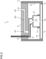
Fig. 2 is a schematic cross-sectional diagram of a waterproof microphone of Example 2; -
Fig. 3 is a schematic cross-sectional diagram of a waterproof microphone of Example 3; -
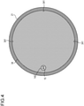
Fig. 4 is a schematic cross-sectional diagram taken along line 4-4 of the waterproof microphone of Example 3; and -
Fig. 5 is a schematic cross-sectional diagram of a waterproof microphone of a modification of Example 3. - Embodiments of the present invention are now described hereinafter in detail. Note that components with the same function are denoted by the same reference numerals; overlapping explanations are omitted accordingly.
- A structure of a waterproof microphone of Example 1 is described hereinafter with reference to
Fig. 1 . As shown in the diagram, a waterproof microphone 1 of the present example includes acase 11, a waterproof vibratingmembrane 12, amicrophone unit 13, asealing member 14, and afilling member 15.Figs. 1 to 3 each omit the illustration of an internal structure of themicrophone unit 13. - The
case 11 includes apartition wall 112 partitioning an internal space of thecase 11 into two chambers, afront chamber 111 and arear chamber 116. Ahole 113 that allows communication between thefront chamber 111 and therear chamber 116 is formed on thepartition wall 112. An opening portion is formed on each of surfaces of thefront chamber 111 and therear chamber 116 that face thepartition wall 112. Thecase 11 may be made of metal such as aluminum, resin, or other materials. In a case where themicrophone unit 13 is an ECM, a substrate of the ECM corresponds to thepartition wall 112. - The waterproof vibrating
membrane 12 covers the opening portion of thefront chamber 111. The waterproofvibrating membrane 12 may be a metallic membrane, a Teflon membrane, a rubber membrane, film, or the like. Because a metallic membrane, a Teflon membrane, a rubber membrane, film or the like can be used as a vibrating plate and vibrations thereof can be received with an internal microphone (the microphone unit 13), a tone hole is omitted. Note that the waterproof vibratingmembrane 12 may be a metallic or resin thin film that does not corrode easily. Acoustic characteristics of the waterproof microphone 1 can be adjusted by changing a thickness and an effective diameter of the waterproof vibratingmembrane 12 and a volume of thefront chamber 111. - The
microphone unit 13 is attached to a surface of thepartition wall 112 on therear chamber 116 side. Asupport member 114 supporting themicrophone unit 13 is formed on the surface of thepartition wall 112 on therear chamber 116 side. Ahole 115 is formed in a lower portion of themicrophone unit 13. Themicrophone unit 13 may be a typical ECM, MEMS microphone, or the like. - The sealing
member 14 seals the opening portion of therear chamber 116 and includes anair hole 141 that allows communication between therear chamber 116 and an external space. Theair hole 141 is a hole that extends while bending multiple times in the sealingmember 14. For example, as shown in the diagram, theair hole 141 is configured by a first vertically stretchedportion 1411 communicating with therear chamber 116 and extending vertically upward, a horizontally stretchedportion 1412 connected to the first vertically stretchedportion 1411 and extending in a horizontal direction, and a second vertically stretchedportion 1413 connected to the horizontally stretchedportion 1412, extending vertically upward, and communicating with the external space. By reducing an inner diameter of theair hole 141 and bending theair hole 141 multiple times as described above to increase a total length thereof, an acoustic impedance can be increased. Accordingly, a sound from the outside is prevented from entering, coping with fluctuations of an internal air pressure. Awiring hole 142 is also formed in the sealingmember 14. - A cable is inserted into the
wiring hole 142, and then thewiring hole 142 is filled with thefilling member 15, thereby sealing thewiring hole 142. - By allowing ting the
front chamber 111 and therear chamber 116 to communicate with the external space, an abnormal alteration of the waterproof vibratingmembrane 12 caused by pressure fluctuations due to changes in temperature and altitude can be prevented. Accordingly, not only is it possible to realize the waterproof microphone 1 that does not break down or deteriorate easily even under bad weather conditions, but also such waterproof microphone 1 can be applied to, for example, a microphone attached to the outside of an automobile. - Also, since the acoustic impedance can be increased by the
air hole 141, the impact on the characteristics of themicrophone unit 13 can be reduced. By reducing the diameter of theair hole 141 and bending theair hole 141 multiple times in the sealingmember 14 as in the example shown inFig. 1 , the waterproof microphone 1 can deal with the pressure fluctuations without impairing the waterproofing property of the waterproof microphone 1. - Since the waterproof microphone 1 of the present example can be realized simply by providing the
hole 113 in thepartition wall 112 and preparing the sealingmember 14 described above, an existing electret condenser microphone and the like can be applied as-is, thereby reducing the cost. - A structure of a waterproof microphone of Example 2 is described hereinafter with reference to
Fig. 2 . As shown in the diagram, awaterproof microphone 2 of the present example includes thecase 21, the waterproof vibratingmembrane 12, amicrophone unit 23, the sealingmember 14, and the fillingmember 15. Thecase 21 and themicrophone unit 23 are the only components with structures different from those of Example 1. The structures of thecase 21 and themicrophone unit 23 are described hereinafter. - In the
case 21, ahole 215 is provided in a position at a lower portion of themicrophone unit 23 that is covered by themicrophone unit 23. Thehole 215 plays a role equivalent to thehole 113 of Example 1. Therefore, thehole 113 is not formed in thecase 21. - The
microphone unit 23 includes asmall hole 231 that penetrates from thefront chamber 111 side to therear chamber 116 side or from therear chamber 116 side to thefront chamber 111 side. In a case where themicrophone unit 23 is a MEMS microphone, it is preferred that thesmall hole 231 be provided in an upper surface of themicrophone unit 23. A ventilation path (shown by a dashed arrow in the diagram) that allows communication between thefront chamber 111 and therear chamber 116 is formed by thesmall hole 231 and thehole 215. - According to the
waterproof microphone 2 of the present example, eliminating thehole 113 can prevent the sound from entering, thereby reducing the impact on the characteristics of themicrophone unit 23. - A structure of a waterproof microphone of Example 3 is described hereinafter with reference to
Figs. 3 and4 . As shown inFig. 3 , a waterproof microphone 3 of the present example includes thecase 21, the waterproof vibratingmembrane 12, themicrophone unit 23, a sealingmember 34, and the fillingmember 15. The sealingmember 34 is the only component with a structure different from that of Example 2. The structure of the sealingmember 34 is described hereinafter. - An
air hole 341 is formed on a side surface of the sealing member 34 (a surface in contact with an inner surface of the case 21). Theair hole 341 is a groove stretched in the vertical direction on the side surface of the sealingmember 34 so as to allow communication between therear chamber 116 and the external space (a groove with a depth of approximately 10 µm. See 341 inFigs. 3 and4 ). As shown inFig. 4 , theair hole 341 may be provided in a plurality of sections. - A structure of a waterproof microphone of a modification of Example 3 is described hereinafter with reference to
Fig. 5 . As shown inFig. 5 , awaterproof microphone 3A of the present modification includes thecase 21, the waterproof vibratingmembrane 12, themicrophone unit 23, a sealingmember 34A, and the fillingmember 15. The sealingmember 34A is the only component with a structure different from that of Example 3. The structure of the sealingmember 34A is described hereinafter. - The sealing
member 34A of the present modification is formed so as to cover an edge surface of the opening portion of the rear chamber 116 (seeFig. 5 ), wherein anair hole 341A is an L-shaped groove that is formed on a surface that is in contact with a side surface of the sealingmember 34A and the edge surface of the opening portion of therear chamber 116. - To obtain a combination not disclosed in
Figs. 1 to 5 , for example, thecase 11, themicrophone unit 13, and the sealing member 34 (or the sealingmember 34A) may be combined. - Since the air hole 341 (
air hole 341A) can be formed as a groove in the sealing member 34 (sealingmember 34A) by means of processing that is finer than that performed in puncturing the sealing member, not providing a bending portion does not lead to deterioration of the waterproofing property. - Since the air hole 341 (
air hole 341A) is formed into the shape described above, the groove can be provided when molding the sealing member 34 (sealingmember 34A), resulting in reducing the number of steps as compared with when puncturing the sealing member later. - Although the sealing member needs to be divided into a plurality of parts and molded in order to provide the sealing member with the air hole having a bending portion, the sealing member can be integrated by forming the air hole 341 (
air hole 341A) into the shape described above, thereby achieving the cost reduction.
Claims (5)
- A waterproof microphone, comprising:a case that includes a partition wall separating an internal space into two chambers, a front chamber and a rear chamber, a hole in the partition wall for allowing communication between the front chamber and the rear chamber, and opening portions in surfaces of the front chamber and the rear chamber that face the partition wall;a waterproof vibrating membrane covering the opening portion of the front chamber;a microphone unit attached to a surface of the partition wall on the front chamber side;and a sealing member sealing the opening portion of the rear chamber and including an air hole allowing communication between the rear chamber and an external space.
- The waterproof microphone according to claim 1, wherein the air hole is a hole that extends while bending multiple times in the sealing member.
- The waterproof microphone according to claim 1, wherein the air hole is a groove that is formed on a side surface of the sealing member.
- The waterproof microphone according to claim 1, wherein the sealing member is formed so as to cover an edge surface of the opening portion of the rear chamber, and the air hole is a groove that is formed on a surface that is in contact with a side surface of the sealing member and the edge surface.
- The waterproof microphone according to any one of claims 1 to 4, wherein the microphone unit includes a small hole that penetrates from the front chamber side to the rear chamber side or from the rear chamber side to the front chamber side, the hole is provided in a position covered by the microphone unit, and a ventilation path allowing communication between the front chamber and the rear chamber is formed by the small hole and the hole.
Applications Claiming Priority (1)
| Application Number | Priority Date | Filing Date | Title |
|---|---|---|---|
| JP2020122086A JP7441132B2 (en) | 2020-07-16 | 2020-07-16 | waterproof microphone |
Publications (2)
| Publication Number | Publication Date |
|---|---|
| EP3941088A1 true EP3941088A1 (en) | 2022-01-19 |
| EP3941088B1 EP3941088B1 (en) | 2023-11-29 |
Family
ID=76890846
Family Applications (1)
| Application Number | Title | Priority Date | Filing Date |
|---|---|---|---|
| EP21184991.4A Active EP3941088B1 (en) | 2020-07-16 | 2021-07-12 | Waterproof microphone |
Country Status (7)
| Country | Link |
|---|---|
| US (1) | US20220021969A1 (en) |
| EP (1) | EP3941088B1 (en) |
| JP (1) | JP7441132B2 (en) |
| KR (1) | KR102857704B1 (en) |
| CN (1) | CN113949975A (en) |
| FI (1) | FI3941088T3 (en) |
| TW (1) | TWI914356B (en) |
Cited By (1)
| Publication number | Priority date | Publication date | Assignee | Title |
|---|---|---|---|---|
| EP4040797A1 (en) * | 2021-02-03 | 2022-08-10 | Hosiden Corporation | Microphone unit |
Families Citing this family (2)
| Publication number | Priority date | Publication date | Assignee | Title |
|---|---|---|---|---|
| CN115379328B (en) * | 2022-09-08 | 2024-02-06 | 河北初光汽车部件有限公司 | Microphone and outside car microphone mount pad outside car |
| US20250113132A1 (en) * | 2023-09-29 | 2025-04-03 | Harman International Industries, Incorporated | Thin panel surface mount microphone |
Citations (4)
| Publication number | Priority date | Publication date | Assignee | Title |
|---|---|---|---|---|
| JPS5339766A (en) | 1976-09-24 | 1978-04-11 | Sumitomo Electric Ind Ltd | Method and apparatus for detecting foreign substance in pellets |
| JP2001313990A (en) * | 2000-04-28 | 2001-11-09 | Uetax Corp | Waterproof microphone |
| US20060140432A1 (en) * | 2004-12-28 | 2006-06-29 | Uetax Corporation | Waterproof microphone |
| EP2490411A1 (en) * | 2009-10-15 | 2012-08-22 | Nec Corporation | Electronic apparatus |
Family Cites Families (16)
| Publication number | Priority date | Publication date | Assignee | Title |
|---|---|---|---|---|
| JP2003244783A (en) * | 2002-02-13 | 2003-08-29 | Seiko Instruments Inc | Waterproof electro-acoustic transducer and portable electronic device equipped with the same |
| JP2005184422A (en) * | 2003-12-19 | 2005-07-07 | Matsushita Electric Works Ltd | Waterproof-structured microphone |
| TWI318077B (en) * | 2006-09-04 | 2009-12-01 | Fortemedia Inc | Electronic device and process for mounting microphone therein |
| CN202799144U (en) * | 2012-08-25 | 2013-03-13 | 歌尔声学股份有限公司 | Micro-electromechanical systems (MEMS) microphone |
| JP6213871B2 (en) * | 2012-12-27 | 2017-10-18 | パナソニックIpマネジメント株式会社 | Waterproof microphone device |
| JP6075163B2 (en) * | 2013-03-29 | 2017-02-08 | 富士通株式会社 | Portable electronic device and waterproofing method for portable electronic device |
| CN103648067B (en) * | 2013-12-26 | 2017-04-05 | 中国电子科技集团公司第三研究所 | A kind of watertight microphone |
| JP6094899B2 (en) * | 2014-07-31 | 2017-03-15 | カシオ計算機株式会社 | Waterproof microphone and equipment that can be worn |
| US10562761B2 (en) * | 2015-11-18 | 2020-02-18 | Kathirgamasundaram Sooriakumar | Waterproof microphone and associated packing techniques |
| US20170180850A1 (en) * | 2015-12-17 | 2017-06-22 | Quanta Computer Inc. | Waterproof electronic device with pressure-equilibrium functions |
| DE102016116424B4 (en) * | 2016-09-02 | 2026-02-05 | Sennheiser Electronic Se & Co. Kg | Microphone unit for an action camera |
| JP2018125810A (en) * | 2017-02-03 | 2018-08-09 | 富士通株式会社 | Electronics |
| CN106851509B (en) * | 2017-03-06 | 2021-02-19 | 瑞声声学科技(深圳)有限公司 | MEMS microphone |
| CN112020865B (en) * | 2018-04-26 | 2022-06-17 | 美商楼氏电子有限公司 | Acoustic components with acoustically transparent diaphragms |
| CN109413554B (en) | 2018-12-14 | 2024-02-20 | 潍坊歌尔微电子有限公司 | Directional MEMS microphone |
| CN110012409A (en) * | 2018-12-31 | 2019-07-12 | 瑞声科技(新加坡)有限公司 | MEMS microphone manufacturing method |
-
2020
- 2020-07-16 JP JP2020122086A patent/JP7441132B2/en active Active
-
2021
- 2021-05-21 TW TW110118389A patent/TWI914356B/en active
- 2021-06-07 KR KR1020210073625A patent/KR102857704B1/en active Active
- 2021-07-09 US US17/371,658 patent/US20220021969A1/en not_active Abandoned
- 2021-07-12 FI FIEP21184991.4T patent/FI3941088T3/en active
- 2021-07-12 EP EP21184991.4A patent/EP3941088B1/en active Active
- 2021-07-13 CN CN202110788155.6A patent/CN113949975A/en active Pending
Patent Citations (4)
| Publication number | Priority date | Publication date | Assignee | Title |
|---|---|---|---|---|
| JPS5339766A (en) | 1976-09-24 | 1978-04-11 | Sumitomo Electric Ind Ltd | Method and apparatus for detecting foreign substance in pellets |
| JP2001313990A (en) * | 2000-04-28 | 2001-11-09 | Uetax Corp | Waterproof microphone |
| US20060140432A1 (en) * | 2004-12-28 | 2006-06-29 | Uetax Corporation | Waterproof microphone |
| EP2490411A1 (en) * | 2009-10-15 | 2012-08-22 | Nec Corporation | Electronic apparatus |
Cited By (1)
| Publication number | Priority date | Publication date | Assignee | Title |
|---|---|---|---|---|
| EP4040797A1 (en) * | 2021-02-03 | 2022-08-10 | Hosiden Corporation | Microphone unit |
Also Published As
| Publication number | Publication date |
|---|---|
| US20220021969A1 (en) | 2022-01-20 |
| FI3941088T3 (en) | 2024-02-08 |
| JP7441132B2 (en) | 2024-02-29 |
| KR20220009867A (en) | 2022-01-25 |
| TW202205877A (en) | 2022-02-01 |
| TWI914356B (en) | 2026-02-11 |
| CN113949975A (en) | 2022-01-18 |
| JP2022018755A (en) | 2022-01-27 |
| KR102857704B1 (en) | 2025-09-11 |
| EP3941088B1 (en) | 2023-11-29 |
Similar Documents
| Publication | Publication Date | Title |
|---|---|---|
| EP3941088B1 (en) | Waterproof microphone | |
| CN107509143B (en) | Speaker system for vehicle and vehicle structure provided with same | |
| US10225645B1 (en) | Speaker box | |
| US8724840B2 (en) | Offset acoustic channel for microphone systems | |
| US10567858B2 (en) | Loudspeaker module and terminal device | |
| EP4550836B1 (en) | Electronic device | |
| EP3343943B1 (en) | Sound emission and collection device | |
| WO2017148009A1 (en) | Loudspeaker module | |
| JP2014200024A (en) | Portable electronic apparatus and waterproof method of the same | |
| EP3650275A1 (en) | Invisible headliner microphone | |
| CN108810769B (en) | Loudspeaker module | |
| US8045744B2 (en) | Door speaker enclosure with integral water barrier and hardware attachment | |
| US5491478A (en) | Seal membrane with integral microphone support | |
| KR101952906B1 (en) | Acoustic device having multiple vibration plates | |
| CN113676582B (en) | Electronic equipment and manufacturing method thereof | |
| US20250063295A1 (en) | Electronic device | |
| JP3204872U (en) | Surface bonded waterproof windproof noise three-dimensional structure applied to planar embedded microphones of electronic devices | |
| CN216905233U (en) | Earphone and earphone assembly | |
| CN218387808U (en) | Microphone mounting structure and electronic equipment with same | |
| KR102161637B1 (en) | Acoustic device having multiple vibration plates | |
| CN222750558U (en) | Waterproof loudspeaker | |
| US10645499B2 (en) | MEMS microphone | |
| US20240406605A1 (en) | Speaker Box | |
| US20250113132A1 (en) | Thin panel surface mount microphone | |
| JP7861160B2 (en) | Closed-type receiver with sound-transmitting interface |
Legal Events
| Date | Code | Title | Description |
|---|---|---|---|
| PUAI | Public reference made under article 153(3) epc to a published international application that has entered the european phase |
Free format text: ORIGINAL CODE: 0009012 |
|
| STAA | Information on the status of an ep patent application or granted ep patent |
Free format text: STATUS: THE APPLICATION HAS BEEN PUBLISHED |
|
| AK | Designated contracting states |
Kind code of ref document: A1 Designated state(s): AL AT BE BG CH CY CZ DE DK EE ES FI FR GB GR HR HU IE IS IT LI LT LU LV MC MK MT NL NO PL PT RO RS SE SI SK SM TR |
|
| STAA | Information on the status of an ep patent application or granted ep patent |
Free format text: STATUS: REQUEST FOR EXAMINATION WAS MADE |
|
| 17P | Request for examination filed |
Effective date: 20220719 |
|
| RBV | Designated contracting states (corrected) |
Designated state(s): AL AT BE BG CH CY CZ DE DK EE ES FI FR GB GR HR HU IE IS IT LI LT LU LV MC MK MT NL NO PL PT RO RS SE SI SK SM TR |
|
| GRAP | Despatch of communication of intention to grant a patent |
Free format text: ORIGINAL CODE: EPIDOSNIGR1 |
|
| STAA | Information on the status of an ep patent application or granted ep patent |
Free format text: STATUS: GRANT OF PATENT IS INTENDED |
|
| INTG | Intention to grant announced |
Effective date: 20230622 |
|
| GRAS | Grant fee paid |
Free format text: ORIGINAL CODE: EPIDOSNIGR3 |
|
| GRAA | (expected) grant |
Free format text: ORIGINAL CODE: 0009210 |
|
| STAA | Information on the status of an ep patent application or granted ep patent |
Free format text: STATUS: THE PATENT HAS BEEN GRANTED |
|
| AK | Designated contracting states |
Kind code of ref document: B1 Designated state(s): AL AT BE BG CH CY CZ DE DK EE ES FI FR GB GR HR HU IE IS IT LI LT LU LV MC MK MT NL NO PL PT RO RS SE SI SK SM TR |
|
| REG | Reference to a national code |
Ref country code: GB Ref legal event code: FG4D |
|
| REG | Reference to a national code |
Ref country code: CH Ref legal event code: EP |
|
| REG | Reference to a national code |
Ref country code: DE Ref legal event code: R096 Ref document number: 602021007216 Country of ref document: DE |
|
| REG | Reference to a national code |
Ref country code: IE Ref legal event code: FG4D |
|
| REG | Reference to a national code |
Ref country code: SE Ref legal event code: TRGR |
|
| REG | Reference to a national code |
Ref country code: FI Ref legal event code: FGE |
|
| REG | Reference to a national code |
Ref country code: LT Ref legal event code: MG9D |
|
| REG | Reference to a national code |
Ref country code: NL Ref legal event code: MP Effective date: 20231129 |
|
| PG25 | Lapsed in a contracting state [announced via postgrant information from national office to epo] |
Ref country code: GR Free format text: LAPSE BECAUSE OF FAILURE TO SUBMIT A TRANSLATION OF THE DESCRIPTION OR TO PAY THE FEE WITHIN THE PRESCRIBED TIME-LIMIT Effective date: 20240301 |
|
| PG25 | Lapsed in a contracting state [announced via postgrant information from national office to epo] |
Ref country code: IS Free format text: LAPSE BECAUSE OF FAILURE TO SUBMIT A TRANSLATION OF THE DESCRIPTION OR TO PAY THE FEE WITHIN THE PRESCRIBED TIME-LIMIT Effective date: 20240329 |
|
| PG25 | Lapsed in a contracting state [announced via postgrant information from national office to epo] |
Ref country code: LT Free format text: LAPSE BECAUSE OF FAILURE TO SUBMIT A TRANSLATION OF THE DESCRIPTION OR TO PAY THE FEE WITHIN THE PRESCRIBED TIME-LIMIT Effective date: 20231129 |
|
| PG25 | Lapsed in a contracting state [announced via postgrant information from national office to epo] |
Ref country code: ES Free format text: LAPSE BECAUSE OF FAILURE TO SUBMIT A TRANSLATION OF THE DESCRIPTION OR TO PAY THE FEE WITHIN THE PRESCRIBED TIME-LIMIT Effective date: 20231129 |
|
| PG25 | Lapsed in a contracting state [announced via postgrant information from national office to epo] |
Ref country code: LT Free format text: LAPSE BECAUSE OF FAILURE TO SUBMIT A TRANSLATION OF THE DESCRIPTION OR TO PAY THE FEE WITHIN THE PRESCRIBED TIME-LIMIT Effective date: 20231129 Ref country code: IS Free format text: LAPSE BECAUSE OF FAILURE TO SUBMIT A TRANSLATION OF THE DESCRIPTION OR TO PAY THE FEE WITHIN THE PRESCRIBED TIME-LIMIT Effective date: 20240329 Ref country code: GR Free format text: LAPSE BECAUSE OF FAILURE TO SUBMIT A TRANSLATION OF THE DESCRIPTION OR TO PAY THE FEE WITHIN THE PRESCRIBED TIME-LIMIT Effective date: 20240301 Ref country code: ES Free format text: LAPSE BECAUSE OF FAILURE TO SUBMIT A TRANSLATION OF THE DESCRIPTION OR TO PAY THE FEE WITHIN THE PRESCRIBED TIME-LIMIT Effective date: 20231129 Ref country code: BG Free format text: LAPSE BECAUSE OF FAILURE TO SUBMIT A TRANSLATION OF THE DESCRIPTION OR TO PAY THE FEE WITHIN THE PRESCRIBED TIME-LIMIT Effective date: 20240229 |
|
| REG | Reference to a national code |
Ref country code: AT Ref legal event code: MK05 Ref document number: 1637334 Country of ref document: AT Kind code of ref document: T Effective date: 20231129 |
|
| PG25 | Lapsed in a contracting state [announced via postgrant information from national office to epo] |
Ref country code: NL Free format text: LAPSE BECAUSE OF FAILURE TO SUBMIT A TRANSLATION OF THE DESCRIPTION OR TO PAY THE FEE WITHIN THE PRESCRIBED TIME-LIMIT Effective date: 20231129 |
|
| PG25 | Lapsed in a contracting state [announced via postgrant information from national office to epo] |
Ref country code: RS Free format text: LAPSE BECAUSE OF FAILURE TO SUBMIT A TRANSLATION OF THE DESCRIPTION OR TO PAY THE FEE WITHIN THE PRESCRIBED TIME-LIMIT Effective date: 20231129 Ref country code: PL Free format text: LAPSE BECAUSE OF FAILURE TO SUBMIT A TRANSLATION OF THE DESCRIPTION OR TO PAY THE FEE WITHIN THE PRESCRIBED TIME-LIMIT Effective date: 20231129 Ref country code: NO Free format text: LAPSE BECAUSE OF FAILURE TO SUBMIT A TRANSLATION OF THE DESCRIPTION OR TO PAY THE FEE WITHIN THE PRESCRIBED TIME-LIMIT Effective date: 20240229 Ref country code: NL Free format text: LAPSE BECAUSE OF FAILURE TO SUBMIT A TRANSLATION OF THE DESCRIPTION OR TO PAY THE FEE WITHIN THE PRESCRIBED TIME-LIMIT Effective date: 20231129 Ref country code: LV Free format text: LAPSE BECAUSE OF FAILURE TO SUBMIT A TRANSLATION OF THE DESCRIPTION OR TO PAY THE FEE WITHIN THE PRESCRIBED TIME-LIMIT Effective date: 20231129 Ref country code: HR Free format text: LAPSE BECAUSE OF FAILURE TO SUBMIT A TRANSLATION OF THE DESCRIPTION OR TO PAY THE FEE WITHIN THE PRESCRIBED TIME-LIMIT Effective date: 20231129 |
|
| PG25 | Lapsed in a contracting state [announced via postgrant information from national office to epo] |
Ref country code: DK Free format text: LAPSE BECAUSE OF FAILURE TO SUBMIT A TRANSLATION OF THE DESCRIPTION OR TO PAY THE FEE WITHIN THE PRESCRIBED TIME-LIMIT Effective date: 20231129 |
|
| PG25 | Lapsed in a contracting state [announced via postgrant information from national office to epo] |
Ref country code: CZ Free format text: LAPSE BECAUSE OF FAILURE TO SUBMIT A TRANSLATION OF THE DESCRIPTION OR TO PAY THE FEE WITHIN THE PRESCRIBED TIME-LIMIT Effective date: 20231129 Ref country code: AT Free format text: LAPSE BECAUSE OF FAILURE TO SUBMIT A TRANSLATION OF THE DESCRIPTION OR TO PAY THE FEE WITHIN THE PRESCRIBED TIME-LIMIT Effective date: 20231129 |
|
| PG25 | Lapsed in a contracting state [announced via postgrant information from national office to epo] |
Ref country code: SK Free format text: LAPSE BECAUSE OF FAILURE TO SUBMIT A TRANSLATION OF THE DESCRIPTION OR TO PAY THE FEE WITHIN THE PRESCRIBED TIME-LIMIT Effective date: 20231129 |
|
| PG25 | Lapsed in a contracting state [announced via postgrant information from national office to epo] |
Ref country code: SM Free format text: LAPSE BECAUSE OF FAILURE TO SUBMIT A TRANSLATION OF THE DESCRIPTION OR TO PAY THE FEE WITHIN THE PRESCRIBED TIME-LIMIT Effective date: 20231129 Ref country code: SK Free format text: LAPSE BECAUSE OF FAILURE TO SUBMIT A TRANSLATION OF THE DESCRIPTION OR TO PAY THE FEE WITHIN THE PRESCRIBED TIME-LIMIT Effective date: 20231129 Ref country code: RO Free format text: LAPSE BECAUSE OF FAILURE TO SUBMIT A TRANSLATION OF THE DESCRIPTION OR TO PAY THE FEE WITHIN THE PRESCRIBED TIME-LIMIT Effective date: 20231129 Ref country code: IT Free format text: LAPSE BECAUSE OF FAILURE TO SUBMIT A TRANSLATION OF THE DESCRIPTION OR TO PAY THE FEE WITHIN THE PRESCRIBED TIME-LIMIT Effective date: 20231129 Ref country code: EE Free format text: LAPSE BECAUSE OF FAILURE TO SUBMIT A TRANSLATION OF THE DESCRIPTION OR TO PAY THE FEE WITHIN THE PRESCRIBED TIME-LIMIT Effective date: 20231129 Ref country code: DK Free format text: LAPSE BECAUSE OF FAILURE TO SUBMIT A TRANSLATION OF THE DESCRIPTION OR TO PAY THE FEE WITHIN THE PRESCRIBED TIME-LIMIT Effective date: 20231129 Ref country code: CZ Free format text: LAPSE BECAUSE OF FAILURE TO SUBMIT A TRANSLATION OF THE DESCRIPTION OR TO PAY THE FEE WITHIN THE PRESCRIBED TIME-LIMIT Effective date: 20231129 Ref country code: AT Free format text: LAPSE BECAUSE OF FAILURE TO SUBMIT A TRANSLATION OF THE DESCRIPTION OR TO PAY THE FEE WITHIN THE PRESCRIBED TIME-LIMIT Effective date: 20231129 |
|
| PG25 | Lapsed in a contracting state [announced via postgrant information from national office to epo] |
Ref country code: PT Free format text: LAPSE BECAUSE OF FAILURE TO SUBMIT A TRANSLATION OF THE DESCRIPTION OR TO PAY THE FEE WITHIN THE PRESCRIBED TIME-LIMIT Effective date: 20240401 |
|
| PG25 | Lapsed in a contracting state [announced via postgrant information from national office to epo] |
Ref country code: PT Free format text: LAPSE BECAUSE OF FAILURE TO SUBMIT A TRANSLATION OF THE DESCRIPTION OR TO PAY THE FEE WITHIN THE PRESCRIBED TIME-LIMIT Effective date: 20240401 |
|
| REG | Reference to a national code |
Ref country code: DE Ref legal event code: R097 Ref document number: 602021007216 Country of ref document: DE |
|
| PLBE | No opposition filed within time limit |
Free format text: ORIGINAL CODE: 0009261 |
|
| STAA | Information on the status of an ep patent application or granted ep patent |
Free format text: STATUS: NO OPPOSITION FILED WITHIN TIME LIMIT |
|
| PG25 | Lapsed in a contracting state [announced via postgrant information from national office to epo] |
Ref country code: SI Free format text: LAPSE BECAUSE OF FAILURE TO SUBMIT A TRANSLATION OF THE DESCRIPTION OR TO PAY THE FEE WITHIN THE PRESCRIBED TIME-LIMIT Effective date: 20231129 |
|
| PG25 | Lapsed in a contracting state [announced via postgrant information from national office to epo] |
Ref country code: SI Free format text: LAPSE BECAUSE OF FAILURE TO SUBMIT A TRANSLATION OF THE DESCRIPTION OR TO PAY THE FEE WITHIN THE PRESCRIBED TIME-LIMIT Effective date: 20231129 |
|
| 26N | No opposition filed |
Effective date: 20240830 |
|
| PG25 | Lapsed in a contracting state [announced via postgrant information from national office to epo] |
Ref country code: MC Free format text: LAPSE BECAUSE OF FAILURE TO SUBMIT A TRANSLATION OF THE DESCRIPTION OR TO PAY THE FEE WITHIN THE PRESCRIBED TIME-LIMIT Effective date: 20231129 |
|
| REG | Reference to a national code |
Ref country code: CH Ref legal event code: PL |
|
| PG25 | Lapsed in a contracting state [announced via postgrant information from national office to epo] |
Ref country code: LU Free format text: LAPSE BECAUSE OF NON-PAYMENT OF DUE FEES Effective date: 20240712 |
|
| PG25 | Lapsed in a contracting state [announced via postgrant information from national office to epo] |
Ref country code: LU Free format text: LAPSE BECAUSE OF NON-PAYMENT OF DUE FEES Effective date: 20240712 |
|
| PG25 | Lapsed in a contracting state [announced via postgrant information from national office to epo] |
Ref country code: BE Free format text: LAPSE BECAUSE OF NON-PAYMENT OF DUE FEES Effective date: 20240731 Ref country code: CH Free format text: LAPSE BECAUSE OF NON-PAYMENT OF DUE FEES Effective date: 20240731 |
|
| REG | Reference to a national code |
Ref country code: BE Ref legal event code: MM Effective date: 20240731 |
|
| PGFP | Annual fee paid to national office [announced via postgrant information from national office to epo] |
Ref country code: GB Payment date: 20250522 Year of fee payment: 5 |
|
| PG25 | Lapsed in a contracting state [announced via postgrant information from national office to epo] |
Ref country code: IE Free format text: LAPSE BECAUSE OF NON-PAYMENT OF DUE FEES Effective date: 20240712 |
|
| PGFP | Annual fee paid to national office [announced via postgrant information from national office to epo] |
Ref country code: SE Payment date: 20250520 Year of fee payment: 5 |
|
| PGFP | Annual fee paid to national office [announced via postgrant information from national office to epo] |
Ref country code: FI Payment date: 20250717 Year of fee payment: 5 |
|
| PGFP | Annual fee paid to national office [announced via postgrant information from national office to epo] |
Ref country code: DE Payment date: 20250731 Year of fee payment: 5 |
|
| PGFP | Annual fee paid to national office [announced via postgrant information from national office to epo] |
Ref country code: FR Payment date: 20250723 Year of fee payment: 5 |
|
| PG25 | Lapsed in a contracting state [announced via postgrant information from national office to epo] |
Ref country code: CY Free format text: LAPSE BECAUSE OF FAILURE TO SUBMIT A TRANSLATION OF THE DESCRIPTION OR TO PAY THE FEE WITHIN THE PRESCRIBED TIME-LIMIT; INVALID AB INITIO Effective date: 20210712 |
|
| PG25 | Lapsed in a contracting state [announced via postgrant information from national office to epo] |
Ref country code: HU Free format text: LAPSE BECAUSE OF FAILURE TO SUBMIT A TRANSLATION OF THE DESCRIPTION OR TO PAY THE FEE WITHIN THE PRESCRIBED TIME-LIMIT; INVALID AB INITIO Effective date: 20210712 |