EP3941039A1 - Light beam generating device, projection device, and light beam generating method - Google Patents
Light beam generating device, projection device, and light beam generating method Download PDFInfo
- Publication number
- EP3941039A1 EP3941039A1 EP21181028.8A EP21181028A EP3941039A1 EP 3941039 A1 EP3941039 A1 EP 3941039A1 EP 21181028 A EP21181028 A EP 21181028A EP 3941039 A1 EP3941039 A1 EP 3941039A1
- Authority
- EP
- European Patent Office
- Prior art keywords
- light beam
- drivers
- beam generating
- bit
- light
- Prior art date
- Legal status (The legal status is an assumption and is not a legal conclusion. Google has not performed a legal analysis and makes no representation as to the accuracy of the status listed.)
- Granted
Links
Images



Classifications
-
- H—ELECTRICITY
- H04—ELECTRIC COMMUNICATION TECHNIQUE
- H04N—PICTORIAL COMMUNICATION, e.g. TELEVISION
- H04N9/00—Details of colour television systems
- H04N9/12—Picture reproducers
- H04N9/31—Projection devices for colour picture display, e.g. using electronic spatial light modulators [ESLM]
- H04N9/3141—Constructional details thereof
- H04N9/315—Modulator illumination systems
- H04N9/3161—Modulator illumination systems using laser light sources
-
- H—ELECTRICITY
- H05—ELECTRIC TECHNIQUES NOT OTHERWISE PROVIDED FOR
- H05B—ELECTRIC HEATING; ELECTRIC LIGHT SOURCES NOT OTHERWISE PROVIDED FOR; CIRCUIT ARRANGEMENTS FOR ELECTRIC LIGHT SOURCES, IN GENERAL
- H05B47/00—Circuit arrangements for operating light sources in general, i.e. where the type of light source is not relevant
- H05B47/10—Controlling the light source
-
- G—PHYSICS
- G03—PHOTOGRAPHY; CINEMATOGRAPHY; ANALOGOUS TECHNIQUES USING WAVES OTHER THAN OPTICAL WAVES; ELECTROGRAPHY; HOLOGRAPHY
- G03B—APPARATUS OR ARRANGEMENTS FOR TAKING PHOTOGRAPHS OR FOR PROJECTING OR VIEWING THEM; APPARATUS OR ARRANGEMENTS EMPLOYING ANALOGOUS TECHNIQUES USING WAVES OTHER THAN OPTICAL WAVES; ACCESSORIES THEREFOR
- G03B21/00—Projectors or projection-type viewers; Accessories therefor
- G03B21/14—Details
- G03B21/20—Lamp housings
-
- G—PHYSICS
- G03—PHOTOGRAPHY; CINEMATOGRAPHY; ANALOGOUS TECHNIQUES USING WAVES OTHER THAN OPTICAL WAVES; ELECTROGRAPHY; HOLOGRAPHY
- G03B—APPARATUS OR ARRANGEMENTS FOR TAKING PHOTOGRAPHS OR FOR PROJECTING OR VIEWING THEM; APPARATUS OR ARRANGEMENTS EMPLOYING ANALOGOUS TECHNIQUES USING WAVES OTHER THAN OPTICAL WAVES; ACCESSORIES THEREFOR
- G03B21/00—Projectors or projection-type viewers; Accessories therefor
- G03B21/14—Details
- G03B21/20—Lamp housings
- G03B21/2006—Lamp housings characterised by the light source
- G03B21/2013—Plural light sources
-
- G—PHYSICS
- G03—PHOTOGRAPHY; CINEMATOGRAPHY; ANALOGOUS TECHNIQUES USING WAVES OTHER THAN OPTICAL WAVES; ELECTROGRAPHY; HOLOGRAPHY
- G03B—APPARATUS OR ARRANGEMENTS FOR TAKING PHOTOGRAPHS OR FOR PROJECTING OR VIEWING THEM; APPARATUS OR ARRANGEMENTS EMPLOYING ANALOGOUS TECHNIQUES USING WAVES OTHER THAN OPTICAL WAVES; ACCESSORIES THEREFOR
- G03B21/00—Projectors or projection-type viewers; Accessories therefor
- G03B21/14—Details
- G03B21/20—Lamp housings
- G03B21/2053—Intensity control of illuminating light
-
- G—PHYSICS
- G03—PHOTOGRAPHY; CINEMATOGRAPHY; ANALOGOUS TECHNIQUES USING WAVES OTHER THAN OPTICAL WAVES; ELECTROGRAPHY; HOLOGRAPHY
- G03B—APPARATUS OR ARRANGEMENTS FOR TAKING PHOTOGRAPHS OR FOR PROJECTING OR VIEWING THEM; APPARATUS OR ARRANGEMENTS EMPLOYING ANALOGOUS TECHNIQUES USING WAVES OTHER THAN OPTICAL WAVES; ACCESSORIES THEREFOR
- G03B21/00—Projectors or projection-type viewers; Accessories therefor
- G03B21/14—Details
- G03B21/20—Lamp housings
- G03B21/206—Control of light source other than position or intensity
-
- H—ELECTRICITY
- H04—ELECTRIC COMMUNICATION TECHNIQUE
- H04N—PICTORIAL COMMUNICATION, e.g. TELEVISION
- H04N9/00—Details of colour television systems
- H04N9/12—Picture reproducers
- H04N9/31—Projection devices for colour picture display, e.g. using electronic spatial light modulators [ESLM]
- H04N9/3102—Projection devices for colour picture display, e.g. using electronic spatial light modulators [ESLM] using two-dimensional electronic spatial light modulators
- H04N9/3111—Projection devices for colour picture display, e.g. using electronic spatial light modulators [ESLM] using two-dimensional electronic spatial light modulators for displaying the colours sequentially, e.g. by using sequentially activated light sources
-
- H—ELECTRICITY
- H04—ELECTRIC COMMUNICATION TECHNIQUE
- H04N—PICTORIAL COMMUNICATION, e.g. TELEVISION
- H04N9/00—Details of colour television systems
- H04N9/12—Picture reproducers
- H04N9/31—Projection devices for colour picture display, e.g. using electronic spatial light modulators [ESLM]
- H04N9/3141—Constructional details thereof
- H04N9/315—Modulator illumination systems
- H04N9/3158—Modulator illumination systems for controlling the spectrum
-
- H—ELECTRICITY
- H04—ELECTRIC COMMUNICATION TECHNIQUE
- H04N—PICTORIAL COMMUNICATION, e.g. TELEVISION
- H04N9/00—Details of colour television systems
- H04N9/12—Picture reproducers
- H04N9/31—Projection devices for colour picture display, e.g. using electronic spatial light modulators [ESLM]
- H04N9/3141—Constructional details thereof
- H04N9/315—Modulator illumination systems
- H04N9/3164—Modulator illumination systems using multiple light sources
-
- H—ELECTRICITY
- H05—ELECTRIC TECHNIQUES NOT OTHERWISE PROVIDED FOR
- H05B—ELECTRIC HEATING; ELECTRIC LIGHT SOURCES NOT OTHERWISE PROVIDED FOR; CIRCUIT ARRANGEMENTS FOR ELECTRIC LIGHT SOURCES, IN GENERAL
- H05B45/00—Circuit arrangements for operating light-emitting diodes [LED]
- H05B45/20—Controlling the colour of the light
Definitions
- the invention relates to a light beam generating device of a projector, and in particular to a light beam generating device adopting a plurality of light sources.
- a blue laser diode (LD) is usually used as the laser light source.
- Blue laser is irradiated onto a phosphor wheel to excite the phosphor of each color to respectively generate different colors of light, such as green light and yellow light.
- Red light is obtained by filtering yellow light via a filter wheel.
- the invention provides a light beam generating device that may solve the issue of low fluorescence conversion rate.
- the light beam generating device of the invention is configured to receive a color control signal and generate a target light beam having a target color.
- the light beam generating device includes a plurality of drivers, a current signal generating circuit, and a control circuit.
- the plurality of drivers are configured to respectively drive a plurality of light-emitting elements according to a plurality of current signals, wherein the plurality of light-emitting elements collectively generate the target light beam.
- the current signal generating circuit is coupled to the plurality of drivers and configured to generate the plurality of current signals according to the color control signal corresponding to the target color.
- the control circuit is coupled to the plurality of drivers and configured to control whether each of the drivers is enabled according to the color control signal.
- the invention provides a projection device including the light beam generating device.
- the light beam generating method of the invention is configured for a light beam generating device and configured receive a color control signal and generate a target light beam having a target color, including: generating a plurality of current signals via a current signal generating circuit of the light beam generating device according to the color control signal corresponding to the target color; driving a plurality of light-emitting elements respectively via a plurality of drivers of the light beam generating device according to the plurality of current signals, wherein the plurality of light-emitting elements collectively generate the target light beam; and controlling whether each of the drivers is enabled via a control circuit of the light beam generating device according to the color control signal.
- the plurality of drivers may comprise a first driver, a second driver, and a third driver.
- the color control signal may comprise three bits, respectively a first bit, a second bit, and a third bit to respectively correspond to three colored lights of different wavelengths.
- control circuit may comprise: a first OR gate configured to perform an OR operation on the first bit and the second bit
- an output signal of the first OR gate may control whether the first driver and the second driver are enabled.
- a second OR gate may be provided configured to perform an OR operation on the second bit and the third bit.
- an output signal of the second OR gate may control whether the third driver is enabled.
- the current signal generating circuit may comprise a plurality of selection circuits respectively coupled to the plurality of drivers.
- each of the selection circuits may be configured to select a current signal from the plurality of current signals to be provided to a corresponding driver according to the color control signal.
- the current signal generating circuit may comprise a first selection circuit coupled to the first driver and which may be configured to select a current signal from the plurality of current signals as a first current signal according to the color control signal.
- the current signal generating circuit may comprise a second selection circuit coupled to the second driver and which may be configured to select a current signal from the plurality of current signals as a second current signal according to the color control signal.
- the current signal generating circuit may comprise a third selection circuit coupled to the third driver and which may be configured to select a current signal from the plurality of current signals as a third current signal according to the color control signal.
- the first driver, the second driver, and the third driver may drive corresponding light-emitting elements according to the first current signal, the second current signal, and the third current signal, respectively.
- the current signal generating circuit may comprise
- the light beam generating device may further comprise a current amplifying circuit coupled between the current signal generating circuit and the plurality of drivers and which may be configured to amplify the plurality of current signals to be provided to the plurality of drivers.
- whether at least one of the plurality of drivers is enabled may be also controlled by an off signal.
- the off signal may indicate a time interval during which a digital micromirror device is turned off.
- whether the plurality of drivers are enabled may be also controlled by a protection signal.
- the protection signal may be related to a rotating speed value of a diffusion wheel.
- whether each of the drivers is enabled may be also controlled by a verification signal, so that an enable time of each of the drivers is staggered.
- the object is also solved by a projection device comprising the light beam generating device as described above.
- a light beam generating method configured for a light beam generating device, wherein the light beam generating method is configured to receive a color control signal and generate a target light beam having a target color, comprising: generating a plurality of current signals via a current signal generating circuit of the light beam generating device according to the color control signal corresponding to the target color; driving a plurality of light-emitting elements respectively via a plurality of drivers of the light beam generating device according to the plurality of current signals, wherein the plurality of light-emitting elements collectively generate the target light beam; and controlling whether each of the drivers is enabled via a control circuit of the light beam generating device according to the color control signal.
- a number of the plurality of drivers may be three.
- the color control signal may comprise at least three bits.
- three of the at least three bits respectively may instruct the plurality of drivers to generate a red light beam, a green light beam, and a blue light beam to form the target color.
- the light beam generating method may further comprise enabling two of the drivers via the control circuit when a first bit of the at least three bits is at a first logic level and a second bit of the at least three bits and a third bit of the at least three bits are both at a second logic level, wherein the target light is a red light.
- the light beam generating method may further comprise enabling all of the drivers via the control circuit when the second bit is at the first logic level and the first bit and the third bit are both at the second logic level, wherein the target color is a green light.
- the light beam generating method may further comprise enabling only one of the drivers via the control circuit when the third bit is at the first logic level and the first bit and the second bit are both at the second logic level, wherein the target color is a blue light.
- the light beam generating method may further comprise performing an OR operation on the first bit and the second bit via the control circuit to generate a first operation result, wherein whether the first driver and the second driver are enabled is controlled by the first operation result; and performing an OR operation on the second bit and the third bit via the control circuit to generate a second operation result, wherein whether the third driver is enabled is controlled by the second operation result.
- the current signal generating circuit comprises a plurality of selection circuits to be respectively coupled to the plurality of drivers
- the light beam generating method may further comprise selecting a current signal from the plurality of current signals via each of the selection circuits according to the color control signal to be provided to a corresponding driver.
- the plurality of drivers may comprise a first driver, a second driver, and a third driver.
- the current signal generating circuit may comprise a first selection circuit, a second selection circuit, and a third selection circuit respectively coupled to the first driver, the second driver, and the third driver
- the light beam generating method may further comprise selecting a current signal from the plurality of current signals as a first current signal via the first selection circuit according to the color control signal; selecting a current signal from the plurality of current signals as a second current signal via the second selection circuit according to the color control signal; selecting a current signal from the plurality of current signals as a third current signal via the third selection circuit according to the color control signal.
- the first driver, the second driver, and the third driver may drive corresponding light-emitting elements according to the first current signal, the second current signal, and the third current signal, respectively.
- the light beam generating device may further comprises a current amplifying circuit coupled between the current signal generating circuit and the plurality of drivers.
- the light beam generating method may further comprise amplifying the plurality of current signals via the current amplifying circuit to be provided to the plurality of drivers.
- whether at least one of the plurality of drivers is enabled may be also controlled by an off signal, and the off signal may indicate a time interval during which a digital micromirror device is turned off.
- whether the plurality of drivers are enabled may be also controlled by a protection signal, and the protection signal is related to a rotating speed value of a diffusion wheel.
- whether each of the drivers is enabled may be also controlled by a verification signal, so that an enable time of each of the drivers is staggered.
- the light beam generating device of the invention directly adopts a plurality of light sources. Therefore, the light beam generating device of the invention may eliminate the phosphor wheel or the filter wheel, thus fundamentally solving the issue of low fluorescence conversion efficiency. Furthermore, the light beam generating device of the invention may also determine the size of the drive current of the light-emitting elements and whether each of the drivers is enabled according to the color control signal. Thereby, the light beam generating device may generate the target light beam by using a single light source or mixing a plurality of light sources, so that the placement of a color gamut may be better adjusted.
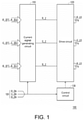
- FIG. 1 shows a block diagram of a light beam generating device of an embodiment of the invention.
- a light beam generating device 100 may be disposed in a projector.
- the function of the light beam generating device 100 is to receive a color control signal 101 and generate a target light beam having a target color.
- the light beam generating device 100 includes a current signal generating circuit 110, a drive circuit 120, and a control circuit 130.
- the current signal generating circuit 110 is coupled to the drive circuit 120 and configured to generate a plurality of current signals according to the color control signal 101 corresponding to the target color. Specifically, the current signal generating circuit 110 may receive current signals R_I(1) to R_I(a) and select one of the current signals R_I(1) to R_I(a) as a first current signal R_I according to the color control signal 101. Similarly, the current signal generating circuit 110 may receive current signals G_I(1) to G_I(b) and select one of the current signals G_I(1) to G_I(b) as a second current signal G_I according to the color control signal 101.
- the current signal generating circuit 110 may receive current signals B_I(1) to B_I(c) and select one of the current signals B_I(1) to B_I(c) as a third current signal B_I according to the color control signal 101.
- a, b, and c are positive integers greater than 1.
- the drive circuit 120 is coupled to the current signal generating circuit 110 to receive the first current signal R_I, the second current signal G_I, and the third current signal B_I.
- the drive circuit 120 may include a plurality of drivers (not shown) respectively coupled to a plurality of light-emitting elements.
- the plurality of drivers may respectively drive the plurality of light-emitting elements according to the first current signal R_I, the second current signal G_I, and the third current signal B_I.
- the drivers may drive different brightness levels or the length of time of light emission in a period according to the duty cycle value of the current signal.
- the drivers when the drivers receive a current signal having a large duty cycle value, the drivers drive the light-emitting elements with a larger current or drive the light-emitting elements to emit light with a longer light-emitting time in a period.
- the plurality of light-emitting elements are driven to collectively generate a target light beam.
- the number of the plurality of drivers included in the drive circuit 120 is three.
- the number of the plurality of light-emitting elements is also three, respectively a first light-emitting element R_LD, a second light-emitting element G_LD, and a third light-emitting element B_LD.
- the first light-emitting element R_LD is driven to emit red light.
- the second light-emitting element G_LD is driven to emit a target light beam to generate a target color, and the target color is, for example, green light.
- the third light emitting element B_LD is driven to emit blue light.
- the light-emitting intensity of each light-emitting element is positively correlated with the current value of the corresponding current signal.
- Each light-emitting element may be a laser diode (LD) or a general light-emitting diode (LED).
- the control circuit 130 is coupled to the drive circuit 120.
- the control circuit 130 receives the color control signal 101 and controls whether the plurality of drivers in the drive circuit 120 are enabled according to the color control signal 101.
- the color control signal 101 is provided to the current signal generating circuit 110.
- the color control signal 101 may be represented as three bits, respectively a first bit R EN, a second bit G_EN, and a third bit B_EN.
- the current signal generating circuit 110 may output the first current signal R_I, the second current signal G_I, and the third current signal B_I according to the color control signal 101.
- each driver in the drive circuit 120 may be enabled or disabled according to the color control signal 101.
- the light beam generating device of the invention 100 adopts a plurality of light sources.
- the light beam generating device 100 may generate a plurality of current signals according to the color control signal 101 to respectively drive a plurality of light-emitting elements to collectively generate a target light beam.
- the light beam generating device 100 may also determine whether each driver is enabled or disabled according to the color control signal 101. That is to say, in addition to controlling the size of the drive current of the light-emitting elements via the color control signal 101, the color control signal 101 may also be used to determine which driver(s) to enable.
- the light beam generating device 100 may generate the target light beam by using a single light source or mixing a plurality of light sources.
- the first light-emitting element R_LD and the third light-emitting element B_LD may be driven at the same time to collectively generate red light.
- the first light-emitting element R_LD and the second light-emitting element G_LD may be driven at the same time to collectively generate red light. Therefore, compared to using a single light source to generate a color screen, in the invention, light may be mixed by two or even three light sources, so that the placement of a color gamut may be adjusted better.
- each bit of the color control signal 101 is level 0 or level 1.
- the three bits of the color control signal 101 may be 000, 001, 010, 011, 100, 101, 110, or 111 (corresponding to 8 states). "1” means at a high logic level, and "0" means at a low logic level.
- the color control signal 101 is configured as "100" to indicate red light timing, "010” to indicate green light timing, and "001" to indicate blue light timing.
- the current signal generating circuit 110 may receive a plurality of groups of current signals, and select and output a corresponding current signal from each group of current signals according to the bit value of the color control signal 101. Each current signal in each group of current signals may be a pulse width modulation (PWM) signal.
- PWM pulse width modulation
- the color control signal 101 may be used as a basis for the current signal generating circuit 110 to select which PWM signal to output (determining the light-emitting intensity of the light-emitting elements).
- each current signal in each group of current signals may also be a direct current signal.
- FIG. 2 shows a block diagram of a light beam generating device of another embodiment of the invention.
- the current signal generating circuit 110 may include three selection circuits 111 to 113 to be respectively coupled to three drivers 121 to 123 in the drive circuit 120.
- the selection circuit 111 has a plurality of input terminals and one output terminal inside. A plurality of input terminals of the selection circuit 111 respectively receive the current signals R_I(1) to R_I(a) (the number of input terminals is consistent with the value of a).
- the duty cycle values represented by the current signals R_I(1) to R_I(a) are different from each other.
- the selection circuit 111 may select one of the output current signals R_I(1) to R_I(a) according to the color control signal 101.
- the architecture and operation mode of the selection circuits 111 and 113 are similar to those of the selection circuit 111, and are therefore not repeated herein.
- the selection circuits 111 to 113 may be data selectors or multiplexers (MUX).
- the circuit structures inside the selection circuits 111 to 113 may be the same.
- the selection circuits 111 to 113 are all multiplexer circuit architectures of three control signals, and the selection circuits 111 to 113 may select one of the current signals R_I(1) to R_I(a), G_I(1) to G_I(b), and B_I(1) to B_I(c) respectively received by a plurality of input terminals for output, wherein the current signals R_I(1) to R_I(a), G_I(1) to G_I(b), and B_I(1) to B_I(c) received by each of the input terminals of each of the selection circuits 111 to 113 may correspond to different duty cycle values.
- the selection circuits 111 to 113 receive the first bit R_EN, the second bit G_EN, and the third bit B_EN in the same configuration, and when the color control signal 101 is in the same state, for example, when the color control signal 101 is "000", the selection circuits 111 to 113 all select and output the current signal of the first input terminal.
- the selection circuit 111 outputs the current signal R_I(1) by coupling the output terminal to an input terminal 111_1.
- the selection circuit 112 outputs the current signal G_I(1) by coupling the output terminal to an input terminal 112_1.
- the selection circuit 111 outputs the current signal B_I(1) by coupling the output terminal to an input terminal 113_1.
- the duty cycle values represented by the current signals R_I(1), G_I(1), and B_I(1) may be different from each other.
- the selection circuits 111 to 113 may all select and output the PWM signals of second input terminals 111_2, 112_2, and 113_2.
- the selection circuits 111 to 113 may all select and output the PWM signals of third input terminals (not shown).
- the case where the color control signal 101 is "010", "011”!111" may be analogized.
- the duty cycle values of the PWM signals received by the input terminals at the same positions of the selection circuits 111 to 113 may be the same, and the selection circuits 111 to 113 receive the first bit R_EN, the second bit G_EN, and the third bit B_EN with different configurations.
- the duty cycle values of the PWM signals received by the first input terminals of the selection circuits 111 to 113 are all 0%.
- the output terminals of the selection circuits 111 to 113 may be connected to input terminals at different positions via the circuit designs thereof to output current signals with different duty cycle values.
- the duty cycle values represented by the plurality of current signals R_I(1) to R_I(a), G_I(1) to G_I(b), and B_I(1) to B_I(c) received by each of the selection circuits 111 to 113 in the 8 states of the color control signal 101 may be designed. That is, when the color control signal 101 is in the same state, different input terminals are outputted.
- the color control signals corresponding to the three primary colors, the first current signal R_I, the second current signal G_I, and the third current signal B_I may be as shown in the following Table (1).
- the values shown in Table (1) are for reference only, and designers may design according to actual requirements, so the values should not be a limitation of the invention.
- the color control signal 101 being "010" may be designed as green light timing
- the first current signal R_I, the second current signal G_I, and the third current signal B_I may be current signals corresponding to duty cycle values of 30%, 90%, and 20%, respectively.
- the second light-emitting element G_LD has the largest light-emitting intensity, and the light-emitting intensities of the first light-emitting element R_LD and the third light-emitting element B_LD are much smaller in comparison.
- color gamut placement may be better controlled.
- each of the selection circuits 111 to 113 includes four input terminals to illustrate the "plurality of' input terminals of each of the selection circuits 111 to 113.
- this does not mean that each of the selection circuits 111 to 113 may only have four input terminals.
- the number of input terminals of the selection circuits 111 to 113 may be other values, for example, 8.
- the number of input terminals of the selection circuits 111 to 113 may be the same as each other, or may be different.
- the drive circuit 120 includes the three drivers 121 to 123.
- the driver 121 is coupled to the selection circuit 111 to receive the first current signal R_I, thereby driving the first light-emitting element R_LD.
- the driver 122 is coupled to the selection circuit 112 to receive the second current signal G_I, thereby driving the second light-emitting element G_LD.
- the driver 123 is coupled to the selection circuit 113 to receive the third current signal B_I, thereby driving the third light-emitting element B_LD.
- the control circuit 130 includes two OR gates 131 and 132.
- the OR gate 131 receives the first bit R_EN and the second bit G_EN of the color control signal 101 to perform an OR operation, and generates control signals R_EN_1 and G_EN_1, thereby controlling whether the drivers 121 and 122 are enabled.
- the OR gate 132 receives the second bit G EN and the third bit B_EN of the color control signal 101 to perform an OR operation, and generates a control signal B_EN_1, thereby controlling whether the driver 123 is enabled.
- the color control signal 101 indicates red light timing with "100".
- the first bit R_EN of the color control signal 101 is at a high voltage level
- the second bit G_EN and the third bit B_EN are both at a low voltage level.
- the OR gate 131 receives the "1" of the first bit R EN and the "0" of the second bit G EN for calculation and outputs "1", and therefore the drivers 121 and 122 are enabled.
- the OR gate 132 receives the "0" of the second bit G EN and the "0" of the third bit B_EN for calculation and outputs "0", and therefore the driver 123 is disabled.
- the color control signal 101 indicates green light timing with "010".
- the first bit R_EN and the third bit B_EN of the color control signal 101 are both at a low voltage level, and the second bit G EN is at a high voltage level.
- the OR gate 131 receives the "0" of the first bit R_EN and the “1” of the second bit G_EN for calculation and outputs "1", and therefore the drivers 121 and 122 are enabled.
- the OR gate 132 receives the "1" of the second bit G_EN and the "0" of the third bit B_EN for calculation and outputs "1", and therefore the driver 123 is enabled. In other words, during green light timing, the drivers 121 to 123 are all enabled.
- the color control signal 101 indicates blue light timing with "001".
- the first bit R_EN and the second bit G_EN of the color control signal 101 are both at a low voltage level, and the third bit B EN is at a high voltage level.
- the OR gate 131 receives the "0" of the first bit R EN and the "0" of the second bit G_EN for calculation and outputs "1", and therefore the drivers 121 and 122 are disabled.
- the OR gate 132 receives the "0" of the second bit G EN and the "1" of the third bit B_EN for calculation and outputs "1", and therefore the driver 123 is enabled. In other words, during blue light timing, only the driver 123 is enabled.
- a single light source (only the driver 123 is enabled) is used to generate blue light.
- the size of the drive current provided to the first light-emitting element R_LD and the second light-emitting element G_LD is 0 (via the selection action of the current signal generating circuit 110) to ensure that blue light is generated via a single light source (i.e., the third light-emitting element B_LD).
- blue light may also be generated in a light mixing manner.
- the color control signal 101 may be four timings, wherein the fourth timing corresponds to compensated color light.
- a color image red screen, blue screen, green screen, and compensation screen
- the color intensity of the first three sub-screens may be reduced and compensated by the fourth sub-screen.
- the four bits of the color control signal 101 may respectively correspond to red light, green light, blue light, and warm color light, and are denoted as RGBM.
- the four timings of the color control signal 101 may correspond to red light, green light, blue light, and yellow light, respectively, and are denoted as RGBY.
- the four timings of the color control signal 101 may correspond to red light, green light, blue light, and white light, respectively, and are denoted as RGBW.
- Warm light, yellow light, or white light may be obtained by mixing the light beams of the first light-emitting element R_LD, the second light-emitting element G_LD, and the third light-emitting element B_LD.
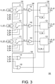
- FIG. 3 shows a block diagram of a light beam generating device of another embodiment of the invention. Please refer to FIG. 3 .
- the difference between the embodiments of FIG. 3 and FIG. 2 is only that a current amplifying circuit 140 is added in FIG. 3 .
- the current amplifying circuit 140 is coupled between the current signal generating circuit 110 and the drive circuit 120.
- the current amplifying circuit 140 has amplifiers 141 to 143 that respectively receive current signals outputted by the selection circuits 111 to 113.
- the amplifiers 141 to 143 are configured to amplify the current signals outputted by the selection circuits 111 to 113, and output the amplified current signals to the drivers 121 to 123, respectively.
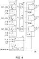
- FIG. 4 shows a block diagram of a light beam generating device of another embodiment of the invention. Please refer to FIG. 4 .
- the difference between the embodiments of FIG. 4 and FIG. 3 is that an AND gate 133 is added to the control circuit 130 of FIG. 4 .
- the AND gate 133 receives the output signal of the OR gate 132 and a general-purpose input/output signal DDP_GPIO (1/99).
- the general-purpose input/output signal DDP_GPIO (1/99) is a flexible software-controlled digital signal.
- the configuration object of the AND gate 133 is explained as follows.
- the projector may modulate light by controlling a light valve.
- the light valve is a digital micro-mirror device (DMD) having a plurality of micro reflective mirrors.
- DMD digital micro-mirror device
- the light valve guides the light beam to one direction by adjusting the DMD. In this way, the light beam is guided into the projection mirror and the light beam is projected by the projector.
- the light valve adjusts the DMD to guide the light beam to other directions different from the direction in the ON state. Therefore, the light beam is not guided into the projection lens, and the projector is stopped from projecting the light beam.
- the DMD needs to swing or swing to the OFF state when the light valve is closed, and the issue of light scurry may occur.
- the light source may be turned off via the AND gate 133 during this time interval.
- the input and output signal DDP_GPIO(1/99) may be at a low voltage level within 1% of the period to disable the driver 123 (because the blue light timing is arranged after the red light timing and the green light timing).
- the drivers 121 to 123 may also all be disabled via circuit design, as illustrated in FIG. 5 .
- FIG. 5 shows a block diagram of a light beam generating device of another embodiment of the invention. Please refer to FIG. 5 .
- the difference between the embodiments of FIG. 5 and FIG. 3 is only that AND gates 133 to 135 are added to the control circuit 130 of FIG. 5 .
- the AND gate 133 receives the output signal of the OR gate 131 and the general-purpose input/output signal DDP_GPIO (1/99), and generates an output signal to the driver 121.
- the AND gate 134 receives the output signal of the OR gate 131 and the general-purpose input/output signal DDP_GPIO (1/99), and generates an output signal to the driver 122.
- the AND gate 135 receives the output signal of the OR gate 132 and the general-purpose input/output signal DDP_GPIO (1/99), and generates an output signal to the driver 123. Therefore, when the general-purpose input/output signal DDP_GPIO (1/99) is at a low voltage level, the drivers 121 to 123 are all disabled to ensure that no light source is generated.
- FIG. 6 shows a block diagram of a light beam generating device of another embodiment of the invention. Please refer to FIG. 6 .
- the difference between the embodiments of FIG. 6 and FIG. 3 is only that the AND gates 133 to 135 and a protection circuit 136 are added to the control circuit 130 of FIG. 6 .
- the AND gate 133 receives the output signal of the OR gate 131 and the output signal of the protection circuit 136, and generates an output signal to the driver 121.
- the protection circuit 136 is configured to receive a signal DS, and the signal DS indicates the rotating speed of a diffuser wheel. The use of the diffuser wheel may make the display screen more uniform.
- the output signal of the protection circuit 136 is at a low voltage level to disable the drivers 121 to 123 to ensure that no light source is generated. In this way, it is possible to avoid the issue that the diffuser wheel is burned out when the light source is continuously generated but the diffuser wheel does not rotate.
- the light beam generating device 100 may be designed to receive any other protection indication signal to disable the drivers 121 to 123 with consideration for the rainbow effect and noise issue.
- the protection indication signal may be related to but not limited to protecting other optical elements such as a color wheel.
- FIG. 7 shows a block diagram of a light beam generating device of another embodiment of the invention. Please refer to FIG. 7 .
- the difference between the embodiments of FIG. 7 and FIG. 3 is only that AND gates 133 to 136 are added to the control circuit 130 of FIG. 7 .
- the AND gate 133 receives the output signal of the OR gate 131 and a verification signal ST1, and generates an output signal to the driver 121.
- the AND gate 134 receives the output signal of the OR gate 131 and a verification signal ST2, and generates an output signal to the driver 122.
- the AND gate 135 receives the output signal of the OR gate 132 and the general-purpose input/output signal DDP_GPIO (1/99), and generates an output signal to the AND gate 136.
- the AND gate 136 receives the output signal of the AND gate 135 and a verification signal ST3, and generates an output signal to the driver 123.
- the production stage of the projector needs to be individually verified for the light sources (R/G/B). Via this mechanism, the light sources may be individually verified during the production stage of the projector.
- FIG. 7 may be modified according to actual needs of users.
- the embodiment shown in FIG. 7 may omit the AND gate 135, so that the output signal of the OR gate 132 may be used as an input signal of the AND gate 136.
- the AND gates 135 and 136 in FIG. 7 may be integrated into one AND gate.
- the AND gate has three input terminals to respectively receive the output signal of the OR gate 132, the input/output signal DDP_GPIO (1/99), and the verification signal ST3.
- FIG. 8 shows a flow chart of the steps of a light beam generating method of another embodiment of the invention.
- the light beam generating method is configured for a light beam generating device and configured to receive a color control signal and generate a target light beam having a target color.
- the steps of the light beam generating method include: generating a plurality of current signals via the current signal generating circuit 110 of the light beam generating device 100 according to the color control signal 101 corresponding to a target color (step S810); driving a plurality of light-emitting elements respectively via a plurality of drivers of the drive circuit 120 of the light beam generating device 100 according to the plurality of current signals, wherein the plurality of light-emitting elements collectively generate a target light beam, so that the plurality of light-emitting elements collectively generate the target light beam (step S820); and controlling whether each of the drivers is enabled via the control circuit 130 of the light beam generating device 100 according to the color control signal 101 (step S830).
- the light beam generating device of the invention directly adopts three primary color light sources. Therefore, the light beam generating device of the invention does not need a phosphor wheel or a filter wheel, thus fundamentally solving the issue of low fluorescence conversion efficiency. At the same time, the issue of rainbow effect and the issue of noise during the operation of the phosphor wheel and the filter wheel may also be avoided.
- the light beam generating device of the invention may also determine the size of the drive current of the light-emitting elements and whether each of the drivers is enabled according to the color control signal. Thereby, the light beam generating device may generate the target light beam by using a single light source or mixing a plurality of light sources, so that the placement of a color gamut may be better adjusted.
- the term "the invention”, “the present invention” or the like does not necessarily limit the claim scope to a specific embodiment, and the reference to particularly preferred exemplary embodiments of the invention does not imply a limitation on the invention, and no such limitation is to be inferred.
- the invention is limited only by the scope of the appended claims. Moreover, these claims may refer to use "first”, “second”, etc. following with noun or element. Such terms should be understood as a nomenclature and should not be construed as giving the limitation on the number of the elements modified by such nomenclature unless specific number has been given.
- the abstract of the disclosure is provided to comply with the rules requiring an abstract, which will allow a searcher to quickly ascertain the subject matter of the technical disclosure of any patent issued from this disclosure.
Landscapes
- Physics & Mathematics (AREA)
- Engineering & Computer Science (AREA)
- Multimedia (AREA)
- Signal Processing (AREA)
- General Physics & Mathematics (AREA)
- Optics & Photonics (AREA)
- Control Of Indicators Other Than Cathode Ray Tubes (AREA)
Abstract
Description
- This application claims the priority benefit of
China application serial no. 202010674679.8, filed on July 14, 2020 - The invention relates to a light beam generating device of a projector, and in particular to a light beam generating device adopting a plurality of light sources.
- In terms of the light source architecture of a projector, a blue laser diode (LD) is usually used as the laser light source. Blue laser is irradiated onto a phosphor wheel to excite the phosphor of each color to respectively generate different colors of light, such as green light and yellow light. Red light is obtained by filtering yellow light via a filter wheel.
- However, the conversion efficiency of using laser to excite phosphors to generate fluorescence is lower, resulting in a higher proportion of laser energy being wasted, and a large amount of heat energy that is difficult to dissipate is also generated in the process. Under the development trend of larger projection sizes, the requirements for projection brightness are higher. Therefore, under the condition of continuously increasing laser excitation power, the issue of low fluorescence conversion efficiency is more prominent. Therefore, it is necessary to propose an effective solution to the issue of low fluorescence conversion rate.
- The information disclosed in this Background section is only for enhancement of understanding of the background of the described technology and therefore it may contain information that does not form the prior art that is already known to a person of ordinary skill in the art. Further, the information disclosed in the Background section does not mean that one or more problems to be resolved by one or more embodiments of the invention was acknowledged by a person of ordinary skill in the art.
- The invention provides a light beam generating device that may solve the issue of low fluorescence conversion rate.
- The object is solved by the features of the independent claims. Preferred embodiments are given in the dependent claims.
- The light beam generating device of the invention is configured to receive a color control signal and generate a target light beam having a target color. The light beam generating device includes a plurality of drivers, a current signal generating circuit, and a control circuit. The plurality of drivers are configured to respectively drive a plurality of light-emitting elements according to a plurality of current signals, wherein the plurality of light-emitting elements collectively generate the target light beam. The current signal generating circuit is coupled to the plurality of drivers and configured to generate the plurality of current signals according to the color control signal corresponding to the target color. The control circuit is coupled to the plurality of drivers and configured to control whether each of the drivers is enabled according to the color control signal.
- The invention provides a projection device including the light beam generating device.
- The light beam generating method of the invention is configured for a light beam generating device and configured receive a color control signal and generate a target light beam having a target color, including: generating a plurality of current signals via a current signal generating circuit of the light beam generating device according to the color control signal corresponding to the target color; driving a plurality of light-emitting elements respectively via a plurality of drivers of the light beam generating device according to the plurality of current signals, wherein the plurality of light-emitting elements collectively generate the target light beam; and controlling whether each of the drivers is enabled via a control circuit of the light beam generating device according to the color control signal.
- In one or more embodiments, which could be combined with other embodiments, the plurality of drivers may comprise a first driver, a second driver, and a third driver.
- In one or more embodiments, which could be combined with other embodiments, the color control signal may comprise three bits, respectively a first bit, a second bit, and a third bit to respectively correspond to three colored lights of different wavelengths.
- In one or more embodiments, which could be combined with other embodiments, the control circuit may comprise: a first OR gate configured to perform an OR operation on the first bit and the second bit
- Preferably, an output signal of the first OR gate may control whether the first driver and the second driver are enabled.
- Preferably, a second OR gate may be provided configured to perform an OR operation on the second bit and the third bit.
- Preferably, an output signal of the second OR gate may control whether the third driver is enabled.
- In one or more embodiments, which could be combined with other embodiments, the current signal generating circuit may comprise a plurality of selection circuits respectively coupled to the plurality of drivers.
- In one or more embodiments, which could be combined with other embodiments, each of the selection circuits may be configured to select a current signal from the plurality of current signals to be provided to a corresponding driver according to the color control signal.
- In one or more embodiments, which could be combined with other embodiments, the current signal generating circuit may comprise a first selection circuit coupled to the first driver and which may be configured to select a current signal from the plurality of current signals as a first current signal according to the color control signal.
- In one or more embodiments, which could be combined with other embodiments, the current signal generating circuit may comprise a second selection circuit coupled to the second driver and which may be configured to select a current signal from the plurality of current signals as a second current signal according to the color control signal.
- In one or more embodiments, which could be combined with other embodiments, the current signal generating circuit may comprise a third selection circuit coupled to the third driver and which may be configured to select a current signal from the plurality of current signals as a third current signal according to the color control signal.
- In one or more embodiments, which could be combined with other embodiments, the first driver, the second driver, and the third driver may drive corresponding light-emitting elements according to the first current signal, the second current signal, and the third current signal, respectively.
- In one or more embodiments, which could be combined with other embodiments, the current signal generating circuit may comprise
- In one or more embodiments, which could be combined with other embodiments, the light beam generating device may further comprise a current amplifying circuit coupled between the current signal generating circuit and the plurality of drivers and which may be configured to amplify the plurality of current signals to be provided to the plurality of drivers.
- In one or more embodiments, which could be combined with other embodiments, whether at least one of the plurality of drivers is enabled may be also controlled by an off signal.
- Preferably, the off signal may indicate a time interval during which a digital micromirror device is turned off.
- In one or more embodiments, which could be combined with other embodiments, whether the plurality of drivers are enabled may be also controlled by a protection signal.
- Preferably, the protection signal may be related to a rotating speed value of a diffusion wheel.
- In one or more embodiments, which could be combined with other embodiments, whether each of the drivers is enabled may be also controlled by a verification signal, so that an enable time of each of the drivers is staggered.
- The object is also solved by a projection device comprising the light beam generating device as described above.
- The object is also solved by a light beam generating method configured for a light beam generating device, wherein the light beam generating method is configured to receive a color control signal and generate a target light beam having a target color, comprising: generating a plurality of current signals via a current signal generating circuit of the light beam generating device according to the color control signal corresponding to the target color; driving a plurality of light-emitting elements respectively via a plurality of drivers of the light beam generating device according to the plurality of current signals, wherein the plurality of light-emitting elements collectively generate the target light beam; and controlling whether each of the drivers is enabled via a control circuit of the light beam generating device according to the color control signal.
- In one or more embodiments, which could be combined with other embodiments, a number of the plurality of drivers may be three.
- In one or more embodiments, which could be combined with other embodiments, the color control signal may comprise at least three bits.
- Preferably, three of the at least three bits respectively may instruct the plurality of drivers to generate a red light beam, a green light beam, and a blue light beam to form the target color.
- In one or more embodiments, which could be combined with other embodiments, the light beam generating method may further comprise enabling two of the drivers via the control circuit when a first bit of the at least three bits is at a first logic level and a second bit of the at least three bits and a third bit of the at least three bits are both at a second logic level, wherein the target light is a red light.
- In one or more embodiments, which could be combined with other embodiments, the light beam generating method may further comprise enabling all of the drivers via the control circuit when the second bit is at the first logic level and the first bit and the third bit are both at the second logic level, wherein the target color is a green light.
- In one or more embodiments, which could be combined with other embodiments, the light beam generating method may further comprise enabling only one of the drivers via the control circuit when the third bit is at the first logic level and the first bit and the second bit are both at the second logic level, wherein the target color is a blue light.
- In one or more embodiments, which could be combined with other embodiments, the light beam generating method may further comprise performing an OR operation on the first bit and the second bit via the control circuit to generate a first operation result, wherein whether the first driver and the second driver are enabled is controlled by the first operation result; and performing an OR operation on the second bit and the third bit via the control circuit to generate a second operation result, wherein whether the third driver is enabled is controlled by the second operation result.
- In one or more embodiments, which could be combined with other embodiments, the current signal generating circuit comprises a plurality of selection circuits to be respectively coupled to the plurality of drivers, and the light beam generating method may further comprise selecting a current signal from the plurality of current signals via each of the selection circuits according to the color control signal to be provided to a corresponding driver.
- In one or more embodiments, which could be combined with other embodiments, the plurality of drivers may comprise a first driver, a second driver, and a third driver.
- In one or more embodiments, which could be combined with other embodiments, the current signal generating circuit may comprise a first selection circuit, a second selection circuit, and a third selection circuit respectively coupled to the first driver, the second driver, and the third driver, and the light beam generating method may further comprise selecting a current signal from the plurality of current signals as a first current signal via the first selection circuit according to the color control signal; selecting a current signal from the plurality of current signals as a second current signal via the second selection circuit according to the color control signal; selecting a current signal from the plurality of current signals as a third current signal via the third selection circuit according to the color control signal.
- Preferably, the first driver, the second driver, and the third driver may drive corresponding light-emitting elements according to the first current signal, the second current signal, and the third current signal, respectively.
- In one or more embodiments, which could be combined with other embodiments, the light beam generating device may further comprises a current amplifying circuit coupled between the current signal generating circuit and the plurality of drivers.
- Preferably, the light beam generating method may further comprise amplifying the plurality of current signals via the current amplifying circuit to be provided to the plurality of drivers.
- In one or more embodiments, which could be combined with other embodiments, whether at least one of the plurality of drivers is enabled may be also controlled by an off signal, and the off signal may indicate a time interval during which a digital micromirror device is turned off.
- In one or more embodiments, which could be combined with other embodiments, whether the plurality of drivers are enabled may be also controlled by a protection signal, and the protection signal is related to a rotating speed value of a diffusion wheel.
- In one or more embodiments, which could be combined with other embodiments, whether each of the drivers is enabled may be also controlled by a verification signal, so that an enable time of each of the drivers is staggered.
- Based on the above, the light beam generating device of the invention directly adopts a plurality of light sources. Therefore, the light beam generating device of the invention may eliminate the phosphor wheel or the filter wheel, thus fundamentally solving the issue of low fluorescence conversion efficiency. Furthermore, the light beam generating device of the invention may also determine the size of the drive current of the light-emitting elements and whether each of the drivers is enabled according to the color control signal. Thereby, the light beam generating device may generate the target light beam by using a single light source or mixing a plurality of light sources, so that the placement of a color gamut may be better adjusted.
- In order to make the above features and advantages of the invention better understood, embodiments are specifically provided below with reference to figures for detailed description as follows.
- Other objectives, features and advantages of the present invention will be further understood from the further technological features disclosed by the embodiments of the present invention wherein there are shown and described preferred embodiments of this invention, simply by way of illustration of modes best suited to carry out the invention.
- The accompanying drawings are included to provide a further understanding of the invention, and are incorporated in and constitute a part of this specification. The drawings illustrate embodiments of the invention and, together with the description, serve to explain the principles of the invention.
-
FIG. 1 shows a block diagram of a light beam generating device of an embodiment of the invention. -
FIG. 2 shows a block diagram of a light beam generating device of another embodiment of the invention. -
FIG. 3 shows a block diagram of a light beam generating device of another embodiment of the invention. -
FIG. 4 shows a block diagram of a light beam generating device of another embodiment of the invention. -
FIG. 5 shows a block diagram of a light beam generating device of another embodiment of the invention. -
FIG. 6 shows a block diagram of a light beam generating device of another embodiment of the invention. -
FIG. 7 shows a block diagram of a light beam generating device of another embodiment of the invention. -
FIG. 8 shows a flow chart of the steps of a light beam generating method of another embodiment of the invention. - It is to be understood that other embodiment may be utilized and structural changes may be made without departing from the scope of the present invention. Also, it is to be understood that the phraseology and terminology used herein are for the purpose of description and should not be regarded as limiting. The use of "including," "comprising," or "having" and variations thereof herein is meant to encompass the items listed thereafter and equivalents thereof as well as additional items. Unless limited otherwise, the terms "connected," "coupled," and "mounted," and variations thereof herein are used broadly and encompass direct and indirect connections, couplings, and mountings.
- The foregoing and other technical content, features, and effects of the invention will be clearly presented in the following detailed description of a preferred embodiment with reference to the accompanying figures. In addition, the terminology mentioned in the embodiments, such as: up, down, left, right, front, rear, etc., are only directions referring to the figures. Therefore, the directional terms used are used for illustration, not for limiting the invention.
-
FIG. 1 shows a block diagram of a light beam generating device of an embodiment of the invention. Please refer toFIG. 1 , a lightbeam generating device 100 may be disposed in a projector. The function of the lightbeam generating device 100 is to receive acolor control signal 101 and generate a target light beam having a target color. The lightbeam generating device 100 includes a currentsignal generating circuit 110, adrive circuit 120, and acontrol circuit 130. - The current
signal generating circuit 110 is coupled to thedrive circuit 120 and configured to generate a plurality of current signals according to thecolor control signal 101 corresponding to the target color. Specifically, the currentsignal generating circuit 110 may receive current signals R_I(1) to R_I(a) and select one of the current signals R_I(1) to R_I(a) as a first current signal R_I according to thecolor control signal 101. Similarly, the currentsignal generating circuit 110 may receive current signals G_I(1) to G_I(b) and select one of the current signals G_I(1) to G_I(b) as a second current signal G_I according to thecolor control signal 101. The currentsignal generating circuit 110 may receive current signals B_I(1) to B_I(c) and select one of the current signals B_I(1) to B_I(c) as a third current signal B_I according to thecolor control signal 101. In particular, a, b, and c are positive integers greater than 1. - The
drive circuit 120 is coupled to the currentsignal generating circuit 110 to receive the first current signal R_I, the second current signal G_I, and the third current signal B_I. Thedrive circuit 120 may include a plurality of drivers (not shown) respectively coupled to a plurality of light-emitting elements. The plurality of drivers may respectively drive the plurality of light-emitting elements according to the first current signal R_I, the second current signal G_I, and the third current signal B_I. Specifically, the drivers may drive different brightness levels or the length of time of light emission in a period according to the duty cycle value of the current signal. For example, when the drivers receive a current signal having a large duty cycle value, the drivers drive the light-emitting elements with a larger current or drive the light-emitting elements to emit light with a longer light-emitting time in a period. The plurality of light-emitting elements are driven to collectively generate a target light beam. In the present embodiment, the number of the plurality of drivers included in thedrive circuit 120 is three. In addition, the number of the plurality of light-emitting elements is also three, respectively a first light-emitting element R_LD, a second light-emitting element G_LD, and a third light-emitting element B_LD. The first light-emitting element R_LD is driven to emit red light. The second light-emitting element G_LD is driven to emit a target light beam to generate a target color, and the target color is, for example, green light. The third light emitting element B_LD is driven to emit blue light. The light-emitting intensity of each light-emitting element is positively correlated with the current value of the corresponding current signal. Each light-emitting element may be a laser diode (LD) or a general light-emitting diode (LED). - The
control circuit 130 is coupled to thedrive circuit 120. Thecontrol circuit 130 receives thecolor control signal 101 and controls whether the plurality of drivers in thedrive circuit 120 are enabled according to thecolor control signal 101. Thecolor control signal 101 is provided to the currentsignal generating circuit 110. In the present embodiment, thecolor control signal 101 may be represented as three bits, respectively a first bit R EN, a second bit G_EN, and a third bit B_EN. The currentsignal generating circuit 110 may output the first current signal R_I, the second current signal G_I, and the third current signal B_I according to thecolor control signal 101. Moreover, each driver in thedrive circuit 120 may be enabled or disabled according to thecolor control signal 101. - As shown in
FIG. 1 , the light beam generating device of theinvention 100 adopts a plurality of light sources. The lightbeam generating device 100 may generate a plurality of current signals according to thecolor control signal 101 to respectively drive a plurality of light-emitting elements to collectively generate a target light beam. It should be mentioned that the lightbeam generating device 100 may also determine whether each driver is enabled or disabled according to thecolor control signal 101. That is to say, in addition to controlling the size of the drive current of the light-emitting elements via thecolor control signal 101, thecolor control signal 101 may also be used to determine which driver(s) to enable. Thereby, the lightbeam generating device 100 may generate the target light beam by using a single light source or mixing a plurality of light sources. In an embodiment, the first light-emitting element R_LD and the third light-emitting element B_LD may be driven at the same time to collectively generate red light. In an embodiment, the first light-emitting element R_LD and the second light-emitting element G_LD may be driven at the same time to collectively generate red light. Therefore, compared to using a single light source to generate a color screen, in the invention, light may be mixed by two or even three light sources, so that the placement of a color gamut may be adjusted better. - In the present embodiment, each bit of the
color control signal 101 is level 0 orlevel 1. The three bits of thecolor control signal 101 may be 000, 001, 010, 011, 100, 101, 110, or 111 (corresponding to 8 states). "1" means at a high logic level, and "0" means at a low logic level. For example, thecolor control signal 101 is configured as "100" to indicate red light timing, "010" to indicate green light timing, and "001" to indicate blue light timing. The currentsignal generating circuit 110 may receive a plurality of groups of current signals, and select and output a corresponding current signal from each group of current signals according to the bit value of thecolor control signal 101. Each current signal in each group of current signals may be a pulse width modulation (PWM) signal. Thecolor control signal 101 may be used as a basis for the currentsignal generating circuit 110 to select which PWM signal to output (determining the light-emitting intensity of the light-emitting elements). In addition, each current signal in each group of current signals may also be a direct current signal. -
FIG. 2 shows a block diagram of a light beam generating device of another embodiment of the invention. Please refer toFIG. 2 , the currentsignal generating circuit 110 may include threeselection circuits 111 to 113 to be respectively coupled to threedrivers 121 to 123 in thedrive circuit 120. Theselection circuit 111 has a plurality of input terminals and one output terminal inside. A plurality of input terminals of theselection circuit 111 respectively receive the current signals R_I(1) to R_I(a) (the number of input terminals is consistent with the value of a). The duty cycle values represented by the current signals R_I(1) to R_I(a) are different from each other. Theselection circuit 111 may select one of the output current signals R_I(1) to R_I(a) according to thecolor control signal 101. The architecture and operation mode of theselection circuits selection circuit 111, and are therefore not repeated herein. Theselection circuits 111 to 113 may be data selectors or multiplexers (MUX). - In the present embodiment, the circuit structures inside the
selection circuits 111 to 113 may be the same. Specifically, theselection circuits 111 to 113 are all multiplexer circuit architectures of three control signals, and theselection circuits 111 to 113 may select one of the current signals R_I(1) to R_I(a), G_I(1) to G_I(b), and B_I(1) to B_I(c) respectively received by a plurality of input terminals for output, wherein the current signals R_I(1) to R_I(a), G_I(1) to G_I(b), and B_I(1) to B_I(c) received by each of the input terminals of each of theselection circuits 111 to 113 may correspond to different duty cycle values. - For example, referring to
FIG. 2 , theselection circuits 111 to 113 receive the first bit R_EN, the second bit G_EN, and the third bit B_EN in the same configuration, and when thecolor control signal 101 is in the same state, for example, when thecolor control signal 101 is "000", theselection circuits 111 to 113 all select and output the current signal of the first input terminal. In other words, theselection circuit 111 outputs the current signal R_I(1) by coupling the output terminal to an input terminal 111_1. Theselection circuit 112 outputs the current signal G_I(1) by coupling the output terminal to an input terminal 112_1. Theselection circuit 111 outputs the current signal B_I(1) by coupling the output terminal to an input terminal 113_1. The duty cycle values represented by the current signals R_I(1), G_I(1), and B_I(1) may be different from each other. When thecolor control signal 101 is "001", theselection circuits 111 to 113 may all select and output the PWM signals of second input terminals 111_2, 112_2, and 113_2. When thecolor control signal 101 is "010", theselection circuits 111 to 113 may all select and output the PWM signals of third input terminals (not shown). The case where thecolor control signal 101 is "010", "011"..."111" may be analogized. - In another embodiment, the duty cycle values of the PWM signals received by the input terminals at the same positions of the
selection circuits 111 to 113 may be the same, and theselection circuits 111 to 113 receive the first bit R_EN, the second bit G_EN, and the third bit B_EN with different configurations. For example, the duty cycle values of the PWM signals received by the first input terminals of theselection circuits 111 to 113 are all 0%. However, under the samecolor control signal 101, the output terminals of theselection circuits 111 to 113 may be connected to input terminals at different positions via the circuit designs thereof to output current signals with different duty cycle values. The duty cycle values represented by the plurality of current signals R_I(1) to R_I(a), G_I(1) to G_I(b), and B_I(1) to B_I(c) received by each of theselection circuits 111 to 113 in the 8 states of thecolor control signal 101 may be designed. That is, when thecolor control signal 101 is in the same state, different input terminals are outputted. - In the present embodiment, the color control signals corresponding to the three primary colors, the first current signal R_I, the second current signal G_I, and the third current signal B_I may be as shown in the following Table (1). The values shown in Table (1) are for reference only, and designers may design according to actual requirements, so the values should not be a limitation of the invention. For example, the
color control signal 101 being "010" may be designed as green light timing, and the first current signal R_I, the second current signal G_I, and the third current signal B_I may be current signals corresponding to duty cycle values of 30%, 90%, and 20%, respectively. In other words, the second light-emitting element G_LD has the largest light-emitting intensity, and the light-emitting intensities of the first light-emitting element R_LD and the third light-emitting element B_LD are much smaller in comparison. Via the light-emitting assistance of the first light-emitting element R_LD and the third light-emitting element B_LD, color gamut placement may be better controlled.Table (1) Color control Signal Duty cycle value corresponding to current signal (%) R_I G_I B_I Red light 100 90 20 0 Green light 010 30 90 20 Blue light 001 0 0 100 - It should be noted that due to the limitation of the drawing space,
FIG. 2 only shows that each of theselection circuits 111 to 113 includes four input terminals to illustrate the "plurality of' input terminals of each of theselection circuits 111 to 113. However, this does not mean that each of theselection circuits 111 to 113 may only have four input terminals. In fact, the number of input terminals of theselection circuits 111 to 113 may be other values, for example, 8. In addition, the number of input terminals of theselection circuits 111 to 113 may be the same as each other, or may be different. - The
drive circuit 120 includes the threedrivers 121 to 123. Thedriver 121 is coupled to theselection circuit 111 to receive the first current signal R_I, thereby driving the first light-emitting element R_LD. Thedriver 122 is coupled to theselection circuit 112 to receive the second current signal G_I, thereby driving the second light-emitting element G_LD. Thedriver 123 is coupled to theselection circuit 113 to receive the third current signal B_I, thereby driving the third light-emitting element B_LD. For example, but not limited to, thecontrol circuit 130 includes two ORgates gate 131 receives the first bit R_EN and the second bit G_EN of thecolor control signal 101 to perform an OR operation, and generates control signals R_EN_1 and G_EN_1, thereby controlling whether thedrivers gate 132 receives the second bit G EN and the third bit B_EN of thecolor control signal 101 to perform an OR operation, and generates a control signal B_EN_1, thereby controlling whether thedriver 123 is enabled. - For example, the
color control signal 101 indicates red light timing with "100". At this time, the first bit R_EN of thecolor control signal 101 is at a high voltage level, and the second bit G_EN and the third bit B_EN are both at a low voltage level. The ORgate 131 receives the "1" of the first bit R EN and the "0" of the second bit G EN for calculation and outputs "1", and therefore thedrivers gate 132 receives the "0" of the second bit G EN and the "0" of the third bit B_EN for calculation and outputs "0", and therefore thedriver 123 is disabled. - The
color control signal 101 indicates green light timing with "010". At this time, the first bit R_EN and the third bit B_EN of thecolor control signal 101 are both at a low voltage level, and the second bit G EN is at a high voltage level. The ORgate 131 receives the "0" of the first bit R_EN and the "1" of the second bit G_EN for calculation and outputs "1", and therefore thedrivers gate 132 receives the "1" of the second bit G_EN and the "0" of the third bit B_EN for calculation and outputs "1", and therefore thedriver 123 is enabled. In other words, during green light timing, thedrivers 121 to 123 are all enabled. - The
color control signal 101 indicates blue light timing with "001". At this time, the first bit R_EN and the second bit G_EN of thecolor control signal 101 are both at a low voltage level, and the third bit B EN is at a high voltage level. The ORgate 131 receives the "0" of the first bit R EN and the "0" of the second bit G_EN for calculation and outputs "1", and therefore thedrivers gate 132 receives the "0" of the second bit G EN and the "1" of the third bit B_EN for calculation and outputs "1", and therefore thedriver 123 is enabled. In other words, during blue light timing, only thedriver 123 is enabled. It should be noted that, in order to pursue maximum brightness under blue light timing, in the present embodiment, a single light source (only thedriver 123 is enabled) is used to generate blue light. In addition, in blue light timing, the size of the drive current provided to the first light-emitting element R_LD and the second light-emitting element G_LD is 0 (via the selection action of the current signal generating circuit 110) to ensure that blue light is generated via a single light source (i.e., the third light-emitting element B_LD). In other embodiments, blue light may also be generated in a light mixing manner. - In another embodiment, the
color control signal 101 may be four timings, wherein the fourth timing corresponds to compensated color light. In other words, a color image (red screen, blue screen, green screen, and compensation screen) is formed via four sub-screens. The color intensity of the first three sub-screens may be reduced and compensated by the fourth sub-screen. For example, the four bits of thecolor control signal 101 may respectively correspond to red light, green light, blue light, and warm color light, and are denoted as RGBM. In other embodiments, the four timings of thecolor control signal 101 may correspond to red light, green light, blue light, and yellow light, respectively, and are denoted as RGBY. Or, the four timings of thecolor control signal 101 may correspond to red light, green light, blue light, and white light, respectively, and are denoted as RGBW. Warm light, yellow light, or white light may be obtained by mixing the light beams of the first light-emitting element R_LD, the second light-emitting element G_LD, and the third light-emitting element B_LD. -
FIG. 3 shows a block diagram of a light beam generating device of another embodiment of the invention. Please refer toFIG. 3 . The difference between the embodiments ofFIG. 3 andFIG. 2 is only that acurrent amplifying circuit 140 is added inFIG. 3 . Thecurrent amplifying circuit 140 is coupled between the currentsignal generating circuit 110 and thedrive circuit 120. Thecurrent amplifying circuit 140 hasamplifiers 141 to 143 that respectively receive current signals outputted by theselection circuits 111 to 113. Theamplifiers 141 to 143 are configured to amplify the current signals outputted by theselection circuits 111 to 113, and output the amplified current signals to thedrivers 121 to 123, respectively. -
FIG. 4 shows a block diagram of a light beam generating device of another embodiment of the invention. Please refer toFIG. 4 . The difference between the embodiments ofFIG. 4 andFIG. 3 is that an ANDgate 133 is added to thecontrol circuit 130 ofFIG. 4 . The ANDgate 133 receives the output signal of theOR gate 132 and a general-purpose input/output signal DDP_GPIO (1/99). The general-purpose input/output signal DDP_GPIO (1/99) is a flexible software-controlled digital signal. The configuration object of the ANDgate 133 is explained as follows. - In the prior art, the projector may modulate light by controlling a light valve. The light valve is a digital micro-mirror device (DMD) having a plurality of micro reflective mirrors. When the light valve is in the ON state, the light valve guides the light beam to one direction by adjusting the DMD. In this way, the light beam is guided into the projection mirror and the light beam is projected by the projector. When the light valve is operated in the OFF state, the light valve adjusts the DMD to guide the light beam to other directions different from the direction in the ON state. Therefore, the light beam is not guided into the projection lens, and the projector is stopped from projecting the light beam.
- However, the DMD needs to swing or swing to the OFF state when the light valve is closed, and the issue of light scurry may occur. To avoid this issue, the light source may be turned off via the AND
gate 133 during this time interval. In the present embodiment, the input and output signal DDP_GPIO(1/99) may be at a low voltage level within 1% of the period to disable the driver 123 (because the blue light timing is arranged after the red light timing and the green light timing). However, this should not be a limitation of the invention. In another embodiment, thedrivers 121 to 123 may also all be disabled via circuit design, as illustrated inFIG. 5 . -
FIG. 5 shows a block diagram of a light beam generating device of another embodiment of the invention. Please refer toFIG. 5 . The difference between the embodiments ofFIG. 5 andFIG. 3 is only that ANDgates 133 to 135 are added to thecontrol circuit 130 ofFIG. 5 . The ANDgate 133 receives the output signal of theOR gate 131 and the general-purpose input/output signal DDP_GPIO (1/99), and generates an output signal to thedriver 121. The ANDgate 134 receives the output signal of theOR gate 131 and the general-purpose input/output signal DDP_GPIO (1/99), and generates an output signal to thedriver 122. The ANDgate 135 receives the output signal of theOR gate 132 and the general-purpose input/output signal DDP_GPIO (1/99), and generates an output signal to thedriver 123. Therefore, when the general-purpose input/output signal DDP_GPIO (1/99) is at a low voltage level, thedrivers 121 to 123 are all disabled to ensure that no light source is generated. -
FIG. 6 shows a block diagram of a light beam generating device of another embodiment of the invention. Please refer toFIG. 6 . The difference between the embodiments ofFIG. 6 andFIG. 3 is only that the ANDgates 133 to 135 and aprotection circuit 136 are added to thecontrol circuit 130 ofFIG. 6 . The ANDgate 133 receives the output signal of theOR gate 131 and the output signal of theprotection circuit 136, and generates an output signal to thedriver 121. Theprotection circuit 136 is configured to receive a signal DS, and the signal DS indicates the rotating speed of a diffuser wheel. The use of the diffuser wheel may make the display screen more uniform. When the signal DS indicates that the rotating speed of the diffuser wheel is 0, the output signal of theprotection circuit 136 is at a low voltage level to disable thedrivers 121 to 123 to ensure that no light source is generated. In this way, it is possible to avoid the issue that the diffuser wheel is burned out when the light source is continuously generated but the diffuser wheel does not rotate. Those skilled in the art may understand that the lightbeam generating device 100 may be designed to receive any other protection indication signal to disable thedrivers 121 to 123 with consideration for the rainbow effect and noise issue. The protection indication signal may be related to but not limited to protecting other optical elements such as a color wheel. -
FIG. 7 shows a block diagram of a light beam generating device of another embodiment of the invention. Please refer toFIG. 7 . The difference between the embodiments ofFIG. 7 andFIG. 3 is only that ANDgates 133 to 136 are added to thecontrol circuit 130 ofFIG. 7 . The ANDgate 133 receives the output signal of theOR gate 131 and a verification signal ST1, and generates an output signal to thedriver 121. The ANDgate 134 receives the output signal of theOR gate 131 and a verification signal ST2, and generates an output signal to thedriver 122. The ANDgate 135 receives the output signal of theOR gate 132 and the general-purpose input/output signal DDP_GPIO (1/99), and generates an output signal to the ANDgate 136. The ANDgate 136 receives the output signal of the ANDgate 135 and a verification signal ST3, and generates an output signal to thedriver 123. The production stage of the projector needs to be individually verified for the light sources (R/G/B). Via this mechanism, the light sources may be individually verified during the production stage of the projector. - It should be noted that the embodiments of
FIG. 3 to FIG. 7 may be modified according to actual needs of users. For example, if the input/output signal DDP_GPIO (1/99) is not needed, the embodiment shown inFIG. 7 may omit the ANDgate 135, so that the output signal of theOR gate 132 may be used as an input signal of the ANDgate 136. Alternatively, the ANDgates FIG. 7 may be integrated into one AND gate. The AND gate has three input terminals to respectively receive the output signal of theOR gate 132, the input/output signal DDP_GPIO (1/99), and the verification signal ST3. -
FIG. 8 shows a flow chart of the steps of a light beam generating method of another embodiment of the invention. The light beam generating method is configured for a light beam generating device and configured to receive a color control signal and generate a target light beam having a target color. Referring toFIG. 1 andFIG. 8 at the same time, the steps of the light beam generating method include: generating a plurality of current signals via the currentsignal generating circuit 110 of the lightbeam generating device 100 according to thecolor control signal 101 corresponding to a target color (step S810); driving a plurality of light-emitting elements respectively via a plurality of drivers of thedrive circuit 120 of the lightbeam generating device 100 according to the plurality of current signals, wherein the plurality of light-emitting elements collectively generate a target light beam, so that the plurality of light-emitting elements collectively generate the target light beam (step S820); and controlling whether each of the drivers is enabled via thecontrol circuit 130 of the lightbeam generating device 100 according to the color control signal 101 (step S830). - Based on the above, different from the prior art that uses a single laser light source with a phosphor wheel and a filter wheel (color wheel) to generate three primary color light sources, the light beam generating device of the invention directly adopts three primary color light sources. Therefore, the light beam generating device of the invention does not need a phosphor wheel or a filter wheel, thus fundamentally solving the issue of low fluorescence conversion efficiency. At the same time, the issue of rainbow effect and the issue of noise during the operation of the phosphor wheel and the filter wheel may also be avoided.
- Furthermore, the light beam generating device of the invention may also determine the size of the drive current of the light-emitting elements and whether each of the drivers is enabled according to the color control signal. Thereby, the light beam generating device may generate the target light beam by using a single light source or mixing a plurality of light sources, so that the placement of a color gamut may be better adjusted.
- The above are only preferred embodiments of the invention, and may not be used to limit the scope of implementation of the invention. That is to say, all simple equivalent changes and modifications made in accordance with the claims of the invention and the content of the specification are still within the scope of the patent of the invention. In addition, the solution of any embodiment or claim of the invention does not need to achieve all the objects or advantages or features disclosed in the invention. In addition, the abstract and the title of the invention are only used to assist the search of patent documents, not to limit the scope of the invention. In addition, terms such as "first" and "second" mentioned in the present specification or claims are only used to name the element or to distinguish different embodiments or ranges, and are not used to limit the upper or lower limit of the number of elements.
- The foregoing description of the preferred embodiments of the invention has been presented for purposes of illustration and description. It is not intended to be exhaustive or to limit the invention to the precise form or to exemplary embodiments disclosed. Accordingly, the foregoing description should be regarded as illustrative rather than restrictive. Obviously, many modifications and variations will be apparent to practitioners skilled in this art. The embodiments are chosen and described in order to best explain the principles of the invention and its best mode practical application, thereby to enable persons skilled in the art to understand the invention for various embodiments and with various modifications as are suited to the particular use or implementation contemplated. It is intended that the scope of the invention be defined by the claims appended hereto and their equivalents in which all terms are meant in their broadest reasonable sense unless otherwise indicated. Therefore, the term "the invention", "the present invention" or the like does not necessarily limit the claim scope to a specific embodiment, and the reference to particularly preferred exemplary embodiments of the invention does not imply a limitation on the invention, and no such limitation is to be inferred. The invention is limited only by the scope of the appended claims. Moreover, these claims may refer to use "first", "second", etc. following with noun or element. Such terms should be understood as a nomenclature and should not be construed as giving the limitation on the number of the elements modified by such nomenclature unless specific number has been given. The abstract of the disclosure is provided to comply with the rules requiring an abstract, which will allow a searcher to quickly ascertain the subject matter of the technical disclosure of any patent issued from this disclosure. It is submitted with the understanding that it will not be used to interpret or limit the scope or meaning of the claims. Any advantages and benefits described may not apply to all embodiments of the invention. It should be appreciated that variations may be made in the embodiments described by persons skilled in the art without departing from the scope of the present invention as defined by the following claims. Moreover, no element and component in the present disclosure is intended to be dedicated to the public regardless of whether the element or component is explicitly recited in the following claims.
Claims (15)
- A light beam generating device, wherein the light beam generating device is configured to receive a color control signal and generate a target light beam having a target color, and the light beam generating device comprises a plurality of drivers, a current signal generating circuit, and a control circuit, wherein:the plurality of drivers respectively drive a plurality of light-emitting elements according to a plurality of current signals, wherein the plurality of light-emitting elements collectively generate the target light beam;the current signal generating circuit is coupled to the plurality of drivers and configured to generate the plurality of current signals according to the color control signal corresponding to the target color; andthe control circuit is coupled to the plurality of drivers and configured to control whether each of the drivers is enabled according to the color control signal.
- The light beam generating device of claim 1, wherein the plurality of drivers comprise a first driver, a second driver, and a third driver, and the color control signal comprise three bits, respectively a first bit, a second bit, and a third bit to respectively correspond to three colored lights of different wavelengths, and the control circuit comprises:a first OR gate configured to perform an OR operation on the first bit and the second bit, wherein an output signal of the first OR gate controls whether the first driver and the second driver are enabled; anda second OR gate configured to perform an OR operation on the second bit and the third bit, wherein an output signal of the second OR gate controls whether the third driver is enabled.
- The light beam generating device of claim 1 or 2, wherein the current signal generating circuit comprises a plurality of selection circuits respectively coupled to the plurality of drivers, and each of the selection circuits is configured to select a current signal from the plurality of current signals to be provided to a corresponding driver according to the color control signal.
- The light beam generating device of any one of the preceding claims, wherein the plurality of drivers comprise a first driver, a second driver, and a third driver, and the current signal generating circuit comprises:a first selection circuit coupled to the first driver and configured to select a current signal from the plurality of current signals as a first current signal according to the color control signal;a second selection circuit coupled to the second driver and configured to select a current signal from the plurality of current signals as a second current signal according to the color control signal;a third selection circuit coupled to the third driver and configured to select a current signal from the plurality of current signals as a third current signal according to the color control signal,wherein the first driver, the second driver, and the third driver drive corresponding light-emitting elements according to the first current signal, the second current signal, and the third current signal, respectively.
- The light beam generating device of any one of the preceding claims, wherein the light beam generating device further comprises a current amplifying circuit coupled between the current signal generating circuit and the plurality of drivers and configured to amplify the plurality of current signals to be provided to the plurality of drivers.
- The light beam generating device of any one of the preceding claims, wherein whether at least one of the plurality of drivers is enabled is also controlled by an off signal, and the off signal indicates a time interval during which a digital micromirror device is turned off.
- The light beam generating device of any one of the preceding claims, wherein whether the plurality of drivers are enabled is also controlled by a protection signal, and the protection signal is related to a rotating speed value of a diffusion wheel.
- The light beam generating device of any one of the preceding claims, wherein whether each of the drivers is enabled is also controlled by a verification signal, so that an enable time of each of the drivers is staggered.
- A projection device comprising the light beam generating device of any one of the preceding claims.
- A light beam generating method configured for a light beam generating device, wherein the light beam generating method is configured to receive a color control signal and generate a target light beam having a target color, comprising:generating a plurality of current signals via a current signal generating circuit of the light beam generating device according to the color control signal corresponding to the target color;driving a plurality of light-emitting elements respectively via a plurality of drivers of the light beam generating device according to the plurality of current signals, wherein the plurality of light-emitting elements collectively generate the target light beam; andcontrolling whether each of the drivers is enabled via a control circuit of the light beam generating device according to the color control signal.
- The light beam generating method of claim 10, wherein a number of the plurality of drivers is three, the color control signal comprises at least three bits, three of the at least three bits respectively instruct the plurality of drivers to generate a red light beam, a green light beam, and a blue light beam to form the target color, and the light beam generating method further comprises:enabling two of the drivers via the control circuit when a first bit of the at least three bits is at a first logic level and a second bit of the at least three bits and a third bit of the at least three bits are both at a second logic level, wherein the target light is a red light.
- The light beam generating method of claim 10 or 11, wherein the light beam generating method further comprises:enabling all of the drivers via the control circuit when the second bit is at the first logic level and the first bit and the third bit are both at the second logic level, wherein the target color is a green light.
- The light beam generating method of any one of claims 10, 11 or 12, wherein the light beam generating method further comprises:enabling only one of the drivers via the control circuit when the third bit is at the first logic level and the first bit and the second bit are both at the second logic level, wherein the target color is a blue light.
- The light beam generating method of any one of claims 10, 11, 12 or 13, wherein the light beam generating method further comprises:performing an OR operation on the first bit and the second bit via the control circuit to generate a first operation result, wherein whether the first driver and the second driver are enabled is controlled by the first operation result; andperforming an OR operation on the second bit and the third bit via the control circuit to generate a second operation result, wherein whether the third driver is enabled is controlled by the second operation result.
- The light beam generating method of any one of claims 10, 11, 12, 13 or 14, wherein the current signal generating circuit comprises a plurality of selection circuits to be respectively coupled to the plurality of drivers, and the light beam generating method further comprises:selecting a current signal from the plurality of current signals via each of the selection circuits according to the color control signal to be provided to a corresponding driver.
Applications Claiming Priority (1)
| Application Number | Priority Date | Filing Date | Title |
|---|---|---|---|
| CN202010674679.8A CN113934094B (en) | 2020-07-14 | 2020-07-14 | Light beam generating device, projection device and light beam generating method |
Publications (2)
| Publication Number | Publication Date |
|---|---|
| EP3941039A1 true EP3941039A1 (en) | 2022-01-19 |
| EP3941039B1 EP3941039B1 (en) | 2024-04-10 |
Family
ID=76584353
Family Applications (1)
| Application Number | Title | Priority Date | Filing Date |
|---|---|---|---|
| EP21181028.8A Active EP3941039B1 (en) | 2020-07-14 | 2021-06-23 | Light beam generating device, projection device, and light beam generating method |
Country Status (3)
| Country | Link |
|---|---|
| US (1) | US11369014B2 (en) |
| EP (1) | EP3941039B1 (en) |
| CN (1) | CN113934094B (en) |
Cited By (1)
| Publication number | Priority date | Publication date | Assignee | Title |
|---|---|---|---|---|
| CN116794917A (en) * | 2022-03-18 | 2023-09-22 | 中强光电股份有限公司 | Projection device, illumination device thereof and light source driving method |
Families Citing this family (1)
| Publication number | Priority date | Publication date | Assignee | Title |
|---|---|---|---|---|
| CN115520087B (en) * | 2022-10-31 | 2024-08-06 | 重庆长安汽车股份有限公司 | Lighting effect entertainment interaction method, device, electronic device and medium for vehicle ground lamp |
Citations (3)
| Publication number | Priority date | Publication date | Assignee | Title |
|---|---|---|---|---|
| US20040036668A1 (en) * | 2002-08-21 | 2004-02-26 | Nec Viewtechnology, Ltd. | Video display device |
| US20120320103A1 (en) * | 2010-01-05 | 2012-12-20 | Jesme Ronald D | Controlling Light Sources for Colour Sequential Image Displaying |
| WO2020108391A1 (en) * | 2018-11-29 | 2020-06-04 | 青岛海信激光显示股份有限公司 | Laser projection display method, and laser projection apparatus |
Family Cites Families (10)
| Publication number | Priority date | Publication date | Assignee | Title |
|---|---|---|---|---|
| US7377657B2 (en) * | 2005-06-01 | 2008-05-27 | Jabil Circuit, Inc. | Image presentation device with light source controller |
| CN102141210A (en) | 2010-02-01 | 2011-08-03 | 深圳市光峰光电技术有限公司 | High color rendering index and high-brightness light lighting equipment and method for realizing multi color temperature regulation |
| JP5769046B2 (en) * | 2010-10-20 | 2015-08-26 | セイコーエプソン株式会社 | Light source control apparatus and method, and projector |
| US11016375B2 (en) * | 2016-01-26 | 2021-05-25 | Barco N.V. | Control of color primaries and white point in a laser-phosphor projector |
| CN108333857B (en) * | 2016-06-30 | 2021-03-09 | 海信集团有限公司 | Projection light source drive control circuit |
| CN108243542B (en) * | 2016-12-26 | 2021-07-27 | 精工爱普生株式会社 | Light emission control circuit, light source device and projection type image display device |
| CN108575029B (en) * | 2017-03-10 | 2020-03-10 | 中强光电股份有限公司 | Projector, light source controller and light source control method |
| CN110320733B (en) * | 2018-03-30 | 2021-10-15 | 中强光电股份有限公司 | Projection system, beam generating device and beam generating method thereof |
| CN111208697B (en) * | 2018-11-22 | 2021-07-27 | 中强光电股份有限公司 | Projection system and control method of driving current thereof |
| CN110401996B (en) | 2019-06-18 | 2021-11-19 | 苏州佳世达光电有限公司 | Projection device and photoelectric coupling circuit thereof |
-
2020
- 2020-07-14 CN CN202010674679.8A patent/CN113934094B/en active Active
-
2021
- 2021-02-03 US US17/167,050 patent/US11369014B2/en active Active
- 2021-06-23 EP EP21181028.8A patent/EP3941039B1/en active Active
Patent Citations (3)
| Publication number | Priority date | Publication date | Assignee | Title |
|---|---|---|---|---|
| US20040036668A1 (en) * | 2002-08-21 | 2004-02-26 | Nec Viewtechnology, Ltd. | Video display device |
| US20120320103A1 (en) * | 2010-01-05 | 2012-12-20 | Jesme Ronald D | Controlling Light Sources for Colour Sequential Image Displaying |
| WO2020108391A1 (en) * | 2018-11-29 | 2020-06-04 | 青岛海信激光显示股份有限公司 | Laser projection display method, and laser projection apparatus |
Cited By (1)
| Publication number | Priority date | Publication date | Assignee | Title |
|---|---|---|---|---|
| CN116794917A (en) * | 2022-03-18 | 2023-09-22 | 中强光电股份有限公司 | Projection device, illumination device thereof and light source driving method |
Also Published As
| Publication number | Publication date |
|---|---|
| CN113934094A (en) | 2022-01-14 |
| EP3941039B1 (en) | 2024-04-10 |
| US11369014B2 (en) | 2022-06-21 |
| CN113934094B (en) | 2023-06-02 |
| US20220022297A1 (en) | 2022-01-20 |
Similar Documents
| Publication | Publication Date | Title |
|---|---|---|
| CN106154720B (en) | A kind of projection light source wwhite balance control circuit | |
| JP5414533B2 (en) | Projection system and method of operating the same | |
| KR101623004B1 (en) | Light source unit and projector | |
| CN101925856B (en) | Multi-color light source | |
| WO2016161934A1 (en) | Projection system and method for controlling color gamut thereof | |
| US10831087B2 (en) | Illumination system and projection apparatus | |
| CN108957931B (en) | White balance adjusting method of laser light source and laser projection equipment | |
| JP2007218956A (en) | Projection type image display device | |
| CN110703553B (en) | Laser projection device | |
| JP5494610B2 (en) | Projection apparatus, projection control method, and program | |
| JPWO2004059608A1 (en) | Projection display device | |
| JP5750572B2 (en) | Projection-type image display device | |
| US11369014B2 (en) | Light beam generating device, projection device, and light beam generating method | |
| JP6379490B2 (en) | Light source driving device and display device | |
| JP6064455B2 (en) | Projection apparatus, projection method, and program | |
| WO2016161933A1 (en) | Projection display system and control method therefor | |
| JP2015219277A (en) | BACKLIGHT DEVICE, LIQUID CRYSTAL DISPLAY DEVICE HAVING THE SAME, AND METHOD FOR DRIVING BACKLIGHT DEVICE | |
| US20250233965A1 (en) | Projection apparatus and projection method | |
| US11323668B2 (en) | Projection device and controlling method of projection device | |
| EP3883240A1 (en) | Projection device and display method thereof | |
| US20090174723A1 (en) | Color display | |
| CN111357283A (en) | Digital spoke-enabled solid state light source when used with a color wheel | |
| KR20120012877A (en) | Device for driving LED light source | |
| US12160692B2 (en) | Projection apparatus, illumination apparatus thereof, and light source driving method thereof | |
| US12380820B2 (en) | Projection device, control circuit and control method thereof |
Legal Events
| Date | Code | Title | Description |
|---|---|---|---|
| PUAI | Public reference made under article 153(3) epc to a published international application that has entered the european phase |
Free format text: ORIGINAL CODE: 0009012 |
|
| STAA | Information on the status of an ep patent application or granted ep patent |
Free format text: STATUS: THE APPLICATION HAS BEEN PUBLISHED |
|
| AK | Designated contracting states |
Kind code of ref document: A1 Designated state(s): AL AT BE BG CH CY CZ DE DK EE ES FI FR GB GR HR HU IE IS IT LI LT LU LV MC MK MT NL NO PL PT RO RS SE SI SK SM TR |
|
| STAA | Information on the status of an ep patent application or granted ep patent |
Free format text: STATUS: REQUEST FOR EXAMINATION WAS MADE |
|
| 17P | Request for examination filed |
Effective date: 20220714 |
|
| RBV | Designated contracting states (corrected) |
Designated state(s): AL AT BE BG CH CY CZ DE DK EE ES FI FR GB GR HR HU IE IS IT LI LT LU LV MC MK MT NL NO PL PT RO RS SE SI SK SM TR |
|
| GRAP | Despatch of communication of intention to grant a patent |
Free format text: ORIGINAL CODE: EPIDOSNIGR1 |
|
| STAA | Information on the status of an ep patent application or granted ep patent |
Free format text: STATUS: GRANT OF PATENT IS INTENDED |
|
| INTG | Intention to grant announced |
Effective date: 20231115 |
|
| GRAS | Grant fee paid |
Free format text: ORIGINAL CODE: EPIDOSNIGR3 |
|
| GRAA | (expected) grant |
Free format text: ORIGINAL CODE: 0009210 |
|
| STAA | Information on the status of an ep patent application or granted ep patent |
Free format text: STATUS: THE PATENT HAS BEEN GRANTED |
|
| AK | Designated contracting states |
Kind code of ref document: B1 Designated state(s): AL AT BE BG CH CY CZ DE DK EE ES FI FR GB GR HR HU IE IS IT LI LT LU LV MC MK MT NL NO PL PT RO RS SE SI SK SM TR |
|
| REG | Reference to a national code |
Ref country code: GB Ref legal event code: FG4D |
|
| REG | Reference to a national code |
Ref country code: CH Ref legal event code: EP |
|
| REG | Reference to a national code |
Ref country code: DE Ref legal event code: R096 Ref document number: 602021011502 Country of ref document: DE |
|
| REG | Reference to a national code |
Ref country code: IE Ref legal event code: FG4D |
|
| REG | Reference to a national code |
Ref country code: LT Ref legal event code: MG9D |
|
| REG | Reference to a national code |
Ref country code: NL Ref legal event code: MP Effective date: 20240410 |
|
| REG | Reference to a national code |
Ref country code: AT Ref legal event code: MK05 Ref document number: 1676086 Country of ref document: AT Kind code of ref document: T Effective date: 20240410 |
|
| PG25 | Lapsed in a contracting state [announced via postgrant information from national office to epo] |
Ref country code: NL Free format text: LAPSE BECAUSE OF FAILURE TO SUBMIT A TRANSLATION OF THE DESCRIPTION OR TO PAY THE FEE WITHIN THE PRESCRIBED TIME-LIMIT Effective date: 20240410 |
|
| PG25 | Lapsed in a contracting state [announced via postgrant information from national office to epo] |
Ref country code: NL Free format text: LAPSE BECAUSE OF FAILURE TO SUBMIT A TRANSLATION OF THE DESCRIPTION OR TO PAY THE FEE WITHIN THE PRESCRIBED TIME-LIMIT Effective date: 20240410 |
|
| PG25 | Lapsed in a contracting state [announced via postgrant information from national office to epo] |
Ref country code: IS Free format text: LAPSE BECAUSE OF FAILURE TO SUBMIT A TRANSLATION OF THE DESCRIPTION OR TO PAY THE FEE WITHIN THE PRESCRIBED TIME-LIMIT Effective date: 20240810 |
|
| PG25 | Lapsed in a contracting state [announced via postgrant information from national office to epo] |
Ref country code: BG Free format text: LAPSE BECAUSE OF FAILURE TO SUBMIT A TRANSLATION OF THE DESCRIPTION OR TO PAY THE FEE WITHIN THE PRESCRIBED TIME-LIMIT Effective date: 20240410 |
|
| PG25 | Lapsed in a contracting state [announced via postgrant information from national office to epo] |
Ref country code: HR Free format text: LAPSE BECAUSE OF FAILURE TO SUBMIT A TRANSLATION OF THE DESCRIPTION OR TO PAY THE FEE WITHIN THE PRESCRIBED TIME-LIMIT Effective date: 20240410 Ref country code: FI Free format text: LAPSE BECAUSE OF FAILURE TO SUBMIT A TRANSLATION OF THE DESCRIPTION OR TO PAY THE FEE WITHIN THE PRESCRIBED TIME-LIMIT Effective date: 20240410 |
|
| PG25 | Lapsed in a contracting state [announced via postgrant information from national office to epo] |
Ref country code: GR Free format text: LAPSE BECAUSE OF FAILURE TO SUBMIT A TRANSLATION OF THE DESCRIPTION OR TO PAY THE FEE WITHIN THE PRESCRIBED TIME-LIMIT Effective date: 20240711 |
|
| PG25 | Lapsed in a contracting state [announced via postgrant information from national office to epo] |
Ref country code: PT Free format text: LAPSE BECAUSE OF FAILURE TO SUBMIT A TRANSLATION OF THE DESCRIPTION OR TO PAY THE FEE WITHIN THE PRESCRIBED TIME-LIMIT Effective date: 20240812 |
|
| PG25 | Lapsed in a contracting state [announced via postgrant information from national office to epo] |
Ref country code: ES Free format text: LAPSE BECAUSE OF FAILURE TO SUBMIT A TRANSLATION OF THE DESCRIPTION OR TO PAY THE FEE WITHIN THE PRESCRIBED TIME-LIMIT Effective date: 20240410 |
|
| PG25 | Lapsed in a contracting state [announced via postgrant information from national office to epo] |
Ref country code: AT Free format text: LAPSE BECAUSE OF FAILURE TO SUBMIT A TRANSLATION OF THE DESCRIPTION OR TO PAY THE FEE WITHIN THE PRESCRIBED TIME-LIMIT Effective date: 20240410 |
|
| PG25 | Lapsed in a contracting state [announced via postgrant information from national office to epo] |
Ref country code: PL Free format text: LAPSE BECAUSE OF FAILURE TO SUBMIT A TRANSLATION OF THE DESCRIPTION OR TO PAY THE FEE WITHIN THE PRESCRIBED TIME-LIMIT Effective date: 20240410 |
|
| PG25 | Lapsed in a contracting state [announced via postgrant information from national office to epo] |
Ref country code: LV Free format text: LAPSE BECAUSE OF FAILURE TO SUBMIT A TRANSLATION OF THE DESCRIPTION OR TO PAY THE FEE WITHIN THE PRESCRIBED TIME-LIMIT Effective date: 20240410 |
|
| PG25 | Lapsed in a contracting state [announced via postgrant information from national office to epo] |
Ref country code: PT Free format text: LAPSE BECAUSE OF FAILURE TO SUBMIT A TRANSLATION OF THE DESCRIPTION OR TO PAY THE FEE WITHIN THE PRESCRIBED TIME-LIMIT Effective date: 20240812 Ref country code: PL Free format text: LAPSE BECAUSE OF FAILURE TO SUBMIT A TRANSLATION OF THE DESCRIPTION OR TO PAY THE FEE WITHIN THE PRESCRIBED TIME-LIMIT Effective date: 20240410 Ref country code: NO Free format text: LAPSE BECAUSE OF FAILURE TO SUBMIT A TRANSLATION OF THE DESCRIPTION OR TO PAY THE FEE WITHIN THE PRESCRIBED TIME-LIMIT Effective date: 20240710 Ref country code: LV Free format text: LAPSE BECAUSE OF FAILURE TO SUBMIT A TRANSLATION OF THE DESCRIPTION OR TO PAY THE FEE WITHIN THE PRESCRIBED TIME-LIMIT Effective date: 20240410 Ref country code: IS Free format text: LAPSE BECAUSE OF FAILURE TO SUBMIT A TRANSLATION OF THE DESCRIPTION OR TO PAY THE FEE WITHIN THE PRESCRIBED TIME-LIMIT Effective date: 20240810 Ref country code: HR Free format text: LAPSE BECAUSE OF FAILURE TO SUBMIT A TRANSLATION OF THE DESCRIPTION OR TO PAY THE FEE WITHIN THE PRESCRIBED TIME-LIMIT Effective date: 20240410 Ref country code: GR Free format text: LAPSE BECAUSE OF FAILURE TO SUBMIT A TRANSLATION OF THE DESCRIPTION OR TO PAY THE FEE WITHIN THE PRESCRIBED TIME-LIMIT Effective date: 20240711 Ref country code: FI Free format text: LAPSE BECAUSE OF FAILURE TO SUBMIT A TRANSLATION OF THE DESCRIPTION OR TO PAY THE FEE WITHIN THE PRESCRIBED TIME-LIMIT Effective date: 20240410 Ref country code: ES Free format text: LAPSE BECAUSE OF FAILURE TO SUBMIT A TRANSLATION OF THE DESCRIPTION OR TO PAY THE FEE WITHIN THE PRESCRIBED TIME-LIMIT Effective date: 20240410 Ref country code: BG Free format text: LAPSE BECAUSE OF FAILURE TO SUBMIT A TRANSLATION OF THE DESCRIPTION OR TO PAY THE FEE WITHIN THE PRESCRIBED TIME-LIMIT Effective date: 20240410 Ref country code: AT Free format text: LAPSE BECAUSE OF FAILURE TO SUBMIT A TRANSLATION OF THE DESCRIPTION OR TO PAY THE FEE WITHIN THE PRESCRIBED TIME-LIMIT Effective date: 20240410 Ref country code: RS Free format text: LAPSE BECAUSE OF FAILURE TO SUBMIT A TRANSLATION OF THE DESCRIPTION OR TO PAY THE FEE WITHIN THE PRESCRIBED TIME-LIMIT Effective date: 20240710 |
|
| REG | Reference to a national code |
Ref country code: DE Ref legal event code: R097 Ref document number: 602021011502 Country of ref document: DE |
|
| PG25 | Lapsed in a contracting state [announced via postgrant information from national office to epo] |
Ref country code: DK Free format text: LAPSE BECAUSE OF FAILURE TO SUBMIT A TRANSLATION OF THE DESCRIPTION OR TO PAY THE FEE WITHIN THE PRESCRIBED TIME-LIMIT Effective date: 20240410 |
|
| PG25 | Lapsed in a contracting state [announced via postgrant information from national office to epo] |
Ref country code: EE Free format text: LAPSE BECAUSE OF FAILURE TO SUBMIT A TRANSLATION OF THE DESCRIPTION OR TO PAY THE FEE WITHIN THE PRESCRIBED TIME-LIMIT Effective date: 20240410 |
|
| PG25 | Lapsed in a contracting state [announced via postgrant information from national office to epo] |
Ref country code: CZ Free format text: LAPSE BECAUSE OF FAILURE TO SUBMIT A TRANSLATION OF THE DESCRIPTION OR TO PAY THE FEE WITHIN THE PRESCRIBED TIME-LIMIT Effective date: 20240410 |
|
| PG25 | Lapsed in a contracting state [announced via postgrant information from national office to epo] |
Ref country code: SK Free format text: LAPSE BECAUSE OF FAILURE TO SUBMIT A TRANSLATION OF THE DESCRIPTION OR TO PAY THE FEE WITHIN THE PRESCRIBED TIME-LIMIT Effective date: 20240410 Ref country code: RO Free format text: LAPSE BECAUSE OF FAILURE TO SUBMIT A TRANSLATION OF THE DESCRIPTION OR TO PAY THE FEE WITHIN THE PRESCRIBED TIME-LIMIT Effective date: 20240410 |
|
| PG25 | Lapsed in a contracting state [announced via postgrant information from national office to epo] |
Ref country code: SM Free format text: LAPSE BECAUSE OF FAILURE TO SUBMIT A TRANSLATION OF THE DESCRIPTION OR TO PAY THE FEE WITHIN THE PRESCRIBED TIME-LIMIT Effective date: 20240410 |
|
| PG25 | Lapsed in a contracting state [announced via postgrant information from national office to epo] |
Ref country code: SM Free format text: LAPSE BECAUSE OF FAILURE TO SUBMIT A TRANSLATION OF THE DESCRIPTION OR TO PAY THE FEE WITHIN THE PRESCRIBED TIME-LIMIT Effective date: 20240410 Ref country code: SK Free format text: LAPSE BECAUSE OF FAILURE TO SUBMIT A TRANSLATION OF THE DESCRIPTION OR TO PAY THE FEE WITHIN THE PRESCRIBED TIME-LIMIT Effective date: 20240410 Ref country code: RO Free format text: LAPSE BECAUSE OF FAILURE TO SUBMIT A TRANSLATION OF THE DESCRIPTION OR TO PAY THE FEE WITHIN THE PRESCRIBED TIME-LIMIT Effective date: 20240410 Ref country code: EE Free format text: LAPSE BECAUSE OF FAILURE TO SUBMIT A TRANSLATION OF THE DESCRIPTION OR TO PAY THE FEE WITHIN THE PRESCRIBED TIME-LIMIT Effective date: 20240410 Ref country code: DK Free format text: LAPSE BECAUSE OF FAILURE TO SUBMIT A TRANSLATION OF THE DESCRIPTION OR TO PAY THE FEE WITHIN THE PRESCRIBED TIME-LIMIT Effective date: 20240410 Ref country code: CZ Free format text: LAPSE BECAUSE OF FAILURE TO SUBMIT A TRANSLATION OF THE DESCRIPTION OR TO PAY THE FEE WITHIN THE PRESCRIBED TIME-LIMIT Effective date: 20240410 Ref country code: MC Free format text: LAPSE BECAUSE OF FAILURE TO SUBMIT A TRANSLATION OF THE DESCRIPTION OR TO PAY THE FEE WITHIN THE PRESCRIBED TIME-LIMIT Effective date: 20240410 |
|
| REG | Reference to a national code |
Ref country code: CH Ref legal event code: PL |
|
| PG25 | Lapsed in a contracting state [announced via postgrant information from national office to epo] |
Ref country code: IT Free format text: LAPSE BECAUSE OF FAILURE TO SUBMIT A TRANSLATION OF THE DESCRIPTION OR TO PAY THE FEE WITHIN THE PRESCRIBED TIME-LIMIT Effective date: 20240410 |
|
| PLBE | No opposition filed within time limit |
Free format text: ORIGINAL CODE: 0009261 |
|
| STAA | Information on the status of an ep patent application or granted ep patent |
Free format text: STATUS: NO OPPOSITION FILED WITHIN TIME LIMIT |
|
| PG25 | Lapsed in a contracting state [announced via postgrant information from national office to epo] |
Ref country code: LU Free format text: LAPSE BECAUSE OF NON-PAYMENT OF DUE FEES Effective date: 20240623 |
|
| 26N | No opposition filed |
Effective date: 20250113 |
|
| PG25 | Lapsed in a contracting state [announced via postgrant information from national office to epo] |
Ref country code: IE Free format text: LAPSE BECAUSE OF NON-PAYMENT OF DUE FEES Effective date: 20240623 |
|
| PG25 | Lapsed in a contracting state [announced via postgrant information from national office to epo] |
Ref country code: CH Free format text: LAPSE BECAUSE OF NON-PAYMENT OF DUE FEES Effective date: 20240630 Ref country code: SI Free format text: LAPSE BECAUSE OF FAILURE TO SUBMIT A TRANSLATION OF THE DESCRIPTION OR TO PAY THE FEE WITHIN THE PRESCRIBED TIME-LIMIT Effective date: 20240410 Ref country code: BE Free format text: LAPSE BECAUSE OF NON-PAYMENT OF DUE FEES Effective date: 20240630 |
|
| REG | Reference to a national code |
Ref country code: BE Ref legal event code: MM Effective date: 20240630 |
|
| PG25 | Lapsed in a contracting state [announced via postgrant information from national office to epo] |
Ref country code: SE Free format text: LAPSE BECAUSE OF FAILURE TO SUBMIT A TRANSLATION OF THE DESCRIPTION OR TO PAY THE FEE WITHIN THE PRESCRIBED TIME-LIMIT Effective date: 20240410 |
|
| PG25 | Lapsed in a contracting state [announced via postgrant information from national office to epo] |
Ref country code: CY Free format text: LAPSE BECAUSE OF FAILURE TO SUBMIT A TRANSLATION OF THE DESCRIPTION OR TO PAY THE FEE WITHIN THE PRESCRIBED TIME-LIMIT; INVALID AB INITIO Effective date: 20210623 |
|
| PG25 | Lapsed in a contracting state [announced via postgrant information from national office to epo] |
Ref country code: HU Free format text: LAPSE BECAUSE OF FAILURE TO SUBMIT A TRANSLATION OF THE DESCRIPTION OR TO PAY THE FEE WITHIN THE PRESCRIBED TIME-LIMIT; INVALID AB INITIO Effective date: 20210623 |
|
| PG25 | Lapsed in a contracting state [announced via postgrant information from national office to epo] |
Ref country code: TR Free format text: LAPSE BECAUSE OF FAILURE TO SUBMIT A TRANSLATION OF THE DESCRIPTION OR TO PAY THE FEE WITHIN THE PRESCRIBED TIME-LIMIT Effective date: 20240410 |
|
| PG25 | Lapsed in a contracting state [announced via postgrant information from national office to epo] |
Ref country code: LT Free format text: LAPSE BECAUSE OF FAILURE TO SUBMIT A TRANSLATION OF THE DESCRIPTION OR TO PAY THE FEE WITHIN THE PRESCRIBED TIME-LIMIT Effective date: 20240410 |
|
| PGFP | Annual fee paid to national office [announced via postgrant information from national office to epo] |
Ref country code: GB Payment date: 20260623 Year of fee payment: 6 |
|
| PGFP | Annual fee paid to national office [announced via postgrant information from national office to epo] |
Ref country code: DE Payment date: 20260629 Year of fee payment: 6 |
|
| PGFP | Annual fee paid to national office [announced via postgrant information from national office to epo] |
Ref country code: FR Payment date: 20260622 Year of fee payment: 6 |