EP3940906A1 - Insulating protective cover body - Google Patents
Insulating protective cover body Download PDFInfo
- Publication number
- EP3940906A1 EP3940906A1 EP19919465.5A EP19919465A EP3940906A1 EP 3940906 A1 EP3940906 A1 EP 3940906A1 EP 19919465 A EP19919465 A EP 19919465A EP 3940906 A1 EP3940906 A1 EP 3940906A1
- Authority
- EP
- European Patent Office
- Prior art keywords
- conductor
- protective cover
- cover body
- insulating protective
- body according
- Prior art date
- Legal status (The legal status is an assumption and is not a legal conclusion. Google has not performed a legal analysis and makes no representation as to the accuracy of the status listed.)
- Granted
Links
Images









Classifications
-
- H—ELECTRICITY
- H02—GENERATION; CONVERSION OR DISTRIBUTION OF ELECTRIC POWER
- H02G—INSTALLATION OF ELECTRIC CABLES OR LINES, OR OF COMBINED OPTICAL AND ELECTRIC CABLES OR LINES
- H02G5/00—Installations of bus-bars
- H02G5/10—Cooling
-
- H—ELECTRICITY
- H02—GENERATION; CONVERSION OR DISTRIBUTION OF ELECTRIC POWER
- H02B—BOARDS, SUBSTATIONS OR SWITCHING ARRANGEMENTS FOR THE SUPPLY OR DISTRIBUTION OF ELECTRIC POWER
- H02B1/00—Frameworks, boards, panels, desks, casings; Details of substations or switching arrangements
- H02B1/20—Bus-bar or other wiring layouts, e.g. in cubicles, in switchyards
-
- H—ELECTRICITY
- H02—GENERATION; CONVERSION OR DISTRIBUTION OF ELECTRIC POWER
- H02G—INSTALLATION OF ELECTRIC CABLES OR LINES, OR OF COMBINED OPTICAL AND ELECTRIC CABLES OR LINES
- H02G5/00—Installations of bus-bars
Definitions
- the present disclosure relates to an insulating protective cover body.
- a plurality of conductors are disposed inside a switchboard used for power receiving/distributing equipment. Fixation portions at which the respective conductors are fixed to the inside of the switchboard, and connection portions connecting the conductors to each other, are disposed inside the switchboard. Insulating protective cover bodies are disposed so as to cover the fixation portions and the connection portions in order to protect the fixation portions and the connection portions from a hand of a person, dust, and the like.
- an insulating protective cover body is made of a dip-molded insulating resin, has a lower end portion serving as a matching surface along horizontal buses, and covers an exposed portion of a connection portion of the horizontal buses (see, for example, Patent Document 1).
- the matching surface is fastened by means of ring-shaped clips.
- connection portion of the horizontal buses is covered by the insulating protective cover body, the connection portion can be protected from a hand of a person, dust, and the like.
- the insulating protective cover body is fastened at the matching surface thereof by means of the ring-shaped clips, and firm fixation by means of the ring-shaped clips leads to absence of a gap between the connection portion of the conductors and the insulating protective cover body.
- no ventilation path can be ensured, whereby a problem arises in that heat dissipation performance deteriorates.
- the present disclosure has been made to solve the aforementioned problems, and an object of the present disclosure is to obtain an insulating protective cover body in which heat dissipation performance is ensured.
- An insulating protective cover body is an insulating protective cover body that surrounds and covers a connection portion at which a first conductor and a second conductor extending in a direction are connected to each other, and has conductor insertion holes provided so as to oppose to each other, the first conductor being inserted in one of the conductor insertion holes, the second conductor being inserted in another one of the conductor insertion holes, wherein the insulating protective cover body is made of a flexible material openable and closable at a cut portion thereof disposed along the direction in which the first conductor and the second conductor extend, and a space serving as a ventilation path in communication with outside is formed between an inner surface of the insulating protective cover body and each of the first conductor and the second conductor.
- the insulating protective cover body according to the present disclosure makes it possible to ensure heat dissipation performance.
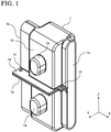
- FIG. 1 is a perspective view of an insulating protective cover body according to embodiment 1.
- FIG. 2 is a top view of the insulating protective cover body attached to a first conductor and a second conductor.
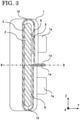
- FIG. 3 is a cross-sectional view taken at the alternate long and short dash line A-A in FIG. 2 .
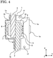
- FIG. 4 is a cross-sectional view taken at the alternate long and short dash line B-B in FIG. 3 .
- FIG. 5 is a partial perspective cross-sectional view of the insulating protective cover body attached to the first conductor and the second conductor.
- FIG. 6 is a front view of the first conductor and the second conductor to be covered by the insulating protective cover body.
- An insulating protective cover body 1 is a cover body made of a flexible material openable and closable at a cut portion thereof disposed along the direction in which a first conductor and a second conductor extend.
- first conductor 2 and a second conductor 3 shown in FIG. 6 the first conductor 2 and the second conductor 3 are connected at two locations by means of conductor connection bolts 4 and conductor connection nuts 7 (not shown in FIG. 6 ) via spring washers 5 and large washers 6.
- the spring washers 5 are used to prevent the conductor connection bolts 4 from loosening, and the large washers 6 are used to increase the areas in which forces of fastening the conductor connection bolts 4 are applied.
- the insulating protective cover body 1 surrounds and covers a connection portion 8 at which the first conductor 2 and the second conductor 3 extending in a direction are connected so as to overlap with each other, and has conductor insertion holes provided so as to oppose to each other, the first conductor 2 being inserted in one of the conductor insertion holes, the second conductor 3 being inserted in another one of the conductor insertion holes.
- This insulating protective cover body 1 will be described below.
- the insulating protective cover body 1 is formed from, for example, vinyl chloride. As shown in FIG. 1 , the insulating protective cover body 1 has a first conductor insertion hole 1b and a second conductor insertion hole 1c opposing to each other, and the first conductor insertion hole 1b and the second conductor insertion hole 1c penetrate inside the insulating protective cover body 1. When the insulating protective cover body 1 covers the connection portion 8 shown in FIG. 6 , the first conductor 2 is inserted from the first conductor insertion hole 1b and the second conductor 3 is inserted from the second conductor insertion hole 1c, as shown in FIG. 2 .
- the insulating protective cover body 1 is formed in such a dimension and a shape that a space serving as a ventilation path 10 in communication with outside is formed between an inner surface 1g of the insulating protective cover body 1 and each of the first conductor 2 and the second conductor 3. Heat generated at each of the first conductor 2, the second conductor 3, and the connection portion 8 is dissipated to outside through the ventilation path 10. Therefore, increases in the temperatures of the first conductor 2, the second conductor 3, and the insulating protective cover body 1 are suppressed.
- the insulating protective cover body 1 includes, at positions thereof opposing to the conductor connection bolts 4 of the connection portion 8, conductor connection bolt cap portions 1a which protrude outward from an outer surface 1h and which have inner sides that are tubular cavity portions 11. Each conductor connection bolt cap portion 1a is fitted to the corresponding conductor connection bolt 4 and formed according to the size of the conductor connection bolt 4. As shown in FIG. 5 , conductor connection bolt fixing projections 1i projecting along a side surface of each cavity portion 11 are disposed. The conductor connection bolt 4 is held by bringing a side surface thereof into contact with the conductor connection bolt fixing projections 1i, and thus the insulating protective cover body 1 does not easily come off from the connection portion 8.
- the cut portion includes a first insulating protective cover body cut portion 1d and a second insulating protective cover body cut portion 1e having cut surfaces which face-to-face oppose to each other.
- the first insulating protective cover body cut portion 1d and the second insulating protective cover body cut portion 1e are provided with insulating protective cover body fastening holes 1f penetrating therethrough.
- Each insulating protective cover body fastening hole 1f is a hole through which the insulating protective cover body 1 is fixed by means of a pin, a bolt, or the like.
- the insulating protective cover body 1 is fixed to the connection portion 8 by using both the conductor connection bolt cap portions 1a and the insulating protective cover body fastening holes 1f, and thus is prevented from coming off owing to vibrations or impact.
- first insulating protective cover body cut portion 1d and the second insulating protective cover body cut portion 1e are gripped so as to open these cut portions, and the connection portion 8 is covered by the insulating protective cover body 1 such that the first conductor 2 and the second conductor 3 shown in FIG. 6 are respectively inserted in the first conductor insertion hole 1b and the second conductor insertion hole 1c.
- the first insulating protective cover body cut portion 1d and the second insulating protective cover body cut portion 1e are closed, and each cavity portion 11 and the corresponding conductor connection bolt 4 are fitted to each other.
- the conductor connection bolt 4 is held by the conductor connection bolt fixing projections 1i so that the insulating protective cover body 1 is stably subjected to primary fixation to the connection portion 8.
- the positions of the insulating protective cover body fastening holes 1f of both the first insulating protective cover body cut portion 1d and the second insulating protective cover body cut portion 1e are matched with each other, and secondary fixation is performed through the insulating protective cover body fastening holes 1f by means of pins or bolts.
- the insulating protective cover body 1 can be subjected to primary fixation by fitting each conductor connection bolt 4 to the corresponding conductor connection bolt cap portion 1a. Therefore, convenience in an attaching operation is improved, and the operation can be performed with one hand in a small space.
- the insulating protective cover body 1 is formed in such a dimension and a shape that the space serving as the ventilation path 10 in communication with outside is formed between the inner surface 1g of the insulating protective cover body 1 and each of the first conductor 2 and the second conductor 3.
- the insulating protective cover body 1 includes the conductor connection bolt cap portions 1a to be fitted to the conductor connection bolts 4 of the connection portion 8 of the conductors.
- the insulating protective cover body 1 can be easily subjected to primary fixation to the connection portion 8.
- the insulating protective cover body 1 can be easily prevented from coming off from the connection portion 8 at the time of primary fixation.
- first insulating protective cover body cut portion 1d and the second insulating protective cover body cut portion 1e are provided with the insulating protective cover body fastening holes 1f penetrating therethrough, and thus secondary fixation can be easily performed through the insulating protective cover body fastening holes 1f by means of pins or bolts, whereby the insulating protective cover body 1 can be prevented from coming off from the connection portion 8.
- each conductor connection bolt cap portion 1a and the corresponding conductor connection bolt 4 are fitted to each other, and thus an attaching operation for the insulating protective cover body 1 can be performed without disposing another member.
- FIG. 7 is a perspective view of the insulating protective cover body 1.
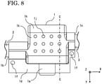
- FIG. 8 is a top view of the insulating protective cover body 1 attached to the first conductor 2 and the second conductor 3.
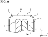
- FIG. 9 is a partial cross-sectional view taken at the alternate long and short dash line C-C in FIG. 8 .
- the insulating protective cover body 1 according to embodiment 2 has a configuration in which ventilation holes 1j are provided in addition to the components of the insulating protective cover body 1 described in embodiment 1.
- the insulating protective cover body 1 is provided with the ventilation holes 1j through which the space serving as the ventilation path 10 and outside are in communication with each other.
- the ventilation holes 1j are provided on each of one side and another side of the insulating protective cover body 1 which oppose to each other.
- 12 ventilation holes 1j are provided in an upper surface 1k on the one side, and 12 ventilation holes 1j (not shown) are provided in the same manner also in a lower surface 11 on the other side. Since the ventilation holes 1j are provided, the outside of the insulating protective cover body 1 and the ventilation path 10 are in close communication with each other. Thus, dissipation of heat generated at each of the first conductor 2, the second conductor 3, and the connection portion 8 to outside is facilitated.
- the ventilation holes 1j are provided in the upper surface 1k and the lower surface 11, air flows are formed such that: air heated inside the ventilation path 10 is discharged from the upper surface 1k; and outside air is introduced from the lower surface 11. Therefore, heat dissipation is further facilitated.
- the present disclosure is not limited to this configuration and may be a configuration in which the ventilation holes 1j are provided in another outer surface 1h. Further, the direction in which the insulating protective cover body 1 is disposed, is not limited to the direction shown in FIG. 7 .
- the ventilation holes 1j through which the space serving as the ventilation path 10 and outside are in communication with each other are provided, dissipation of heat generated at the connection portion 8 to outside can be facilitated.
- the ventilation holes 1j are provided in the upper surface 1k and the lower surface 11, air flows are formed from the lower surface 11 toward the upper surface 1k, and heat dissipation can be further facilitated.
- FIG. 10 is a cross-sectional view of the insulating protective cover body 1 attached to the first conductor 2 and the second conductor 3.
- FIG. 11 is a cross-sectional view taken at the alternate long and short dash line D-D in FIG. 10 .
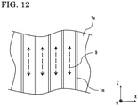
- FIG. 12 is a partial plan view of the inner surface 1g of the insulating protective cover body 1.
- the insulating protective cover body 1 according to embodiment 3 has a configuration in which linear projections 1m which are projections are disposed on the inner surface 1g in addition to the components of the insulating protective cover body 1 described in embodiment 1.
- the linear projections 1m are a plurality of linear protrusions disposed in a direction intersecting with the direction in which the first conductor 2 and the second conductor 3 extend.
- the linear protrusions are disposed between the first conductor insertion hole 1b which is the one of the conductor insertion holes and the second conductor insertion hole 1c which is the other one of the conductor insertion holes. Since the linear projections 1m are provided, the first conductor 2 and the second conductor 3 can be assuredly separated from the inner surface 1g. Since the first conductor 2 and the second conductor 3 are separated from the inner surface 1g so that air spaces are interposed therebetween, increase in the temperature of the insulating protective cover body 1 is suppressed.
- the plurality of linear projections 1m which are projections are disposed, on the inner surface 1g, between the first conductor insertion hole 1b and the second conductor insertion hole 1c.
- the first conductor 2 and the second conductor 3 are assuredly separated from the inner surface 1g, whereby increase in the temperature of the insulating protective cover body 1 can be suppressed.
- the air flows 9 are formed along the linear projections 1m, dissipation of heat generated at each of the first conductor 2, the second conductor 3, and the connection portion 8 to outside is facilitated.
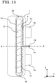
- FIG. 13 is a cross-sectional view of the insulating protective cover body 1 attached to the first conductor 2 and the second conductor 3.
- FIG. 14 is a cross-sectional view taken at the alternate long and short dash line E-E in FIG. 13 .
- FIG. 15 is a partial plan view of the inner surface 1g of the insulating protective cover body 1.
- the insulating protective cover body 1 according to embodiment 4 has a configuration in which hemispheric projections 1n which are projections are disposed on the inner surface 1g in addition to the components of the insulating protective cover body 1 described in embodiment 1.
- the hemispheric projections 1n are hemispheric protrusions arranged in a staggered pattern between the first conductor insertion hole 1b which is the one of the conductor insertion holes and the second conductor insertion hole 1c which is the other one of the conductor insertion holes. Since the hemispheric projections 1n are provided, the first conductor 2 and the second conductor 3 can be assuredly separated from the inner surface 1g. Since the first conductor 2 and the second conductor 3 are separated from the inner surface 1g so that air spaces are interposed therebetween, increase in the temperature of the insulating protective cover body 1 is suppressed.
- the hemispheric projections 1n which are projections are arranged, on the inner surface 1g, in a staggered pattern between the first conductor insertion hole 1b and the second conductor insertion hole 1c.
- the first conductor 2 and the second conductor 3 are assuredly separated from the inner surface 1g, whereby increase in the temperature of the insulating protective cover body 1 can be suppressed.
- the air flows 9 are formed along the paths between the hemispheric projections 1n, dissipation of heat generated at each of the first conductor 2, the second conductor 3, and the connection portion 8 to outside is facilitated.
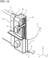
- FIG. 16 is a perspective cross-sectional view showing, in a partially cut manner, the insulating protective cover body according to embodiment 5 in a state of being attached to the first conductor 2 and the second conductor 3.
- the insulating protective cover body 1 according to embodiment 5 has a configuration in which the linear projections 1m described in embodiment 3 are disposed on the inner surface 1g in addition to the components of the insulating protective cover body 1 including the ventilation holes 1j described in embodiment 2.
- the ventilation holes 1j through which the space serving as the ventilation path 10 and outside are in communication with each other are provided in each of the upper surface 1k and the lower surface 11.
- the linear projections 1m are a plurality of linear protrusions disposed between the first conductor insertion hole 1b and the second conductor insertion hole 1c. Since both the ventilation holes 1j and the linear projections 1m are provided to the insulating protective cover body 1, the air flows 9 from the ventilation holes 1j (not shown) in the lower surface 11 toward the ventilation holes 1j in the upper surface 1k are formed along the linear projections 1m.
- air in the ventilation path 10 can be more efficiently circulated, whereby dissipation of heat generated at each of the first conductor 2, the second conductor 3, and the connection portion 8 to outside is facilitated.
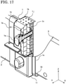
- the present disclosure is not limited to this configuration and may be a configuration in which, as shown in FIG. 17 , the hemispheric projections 1n described in embodiment 4 are disposed on the inner surface 1g in addition to the components of the insulating protective cover body 1 including the ventilation holes 1j described in embodiment 2.
- the air flows 9 from the ventilation holes 1j in the lower surface 11 toward the ventilation holes 1j in the upper surface 1k are formed along the paths between the hemispheric projections In.
- air in the ventilation path 10 can be more efficiently circulated, whereby dissipation of heat generated at the connection portion 8 to outside is facilitated.
- the linear projections 1m are disposed on the inner surface 1g in addition to the components of the insulating protective cover body 1 including the ventilation holes 1j. Consequently, the air flows 9 from the ventilation holes 1j in the lower surface 11 toward the ventilation holes 1j in the upper surface 1k are formed along the linear projections 1m.
- air in the ventilation path 10 can be more efficiently circulated, whereby dissipation of heat generated at each of the first conductor 2, the second conductor 3, and the connection portion 8 to outside can be facilitated.
- the insulating protective cover body is used for insulation and protection of the connection portion of the conductors.
- the present disclosure is not limited this case.
- the insulating protective cover body can be used also for structures shown in FIG. 18 and FIG. 19 .
- An insulating protective cover body 1 shown in FIG. 18 covers a portion at which an insulator 12 is disposed to maintain the insulation distance between the first conductor 2 and the second conductor 3.
- a cut portion 13 is disposed at a lower portion of the insulating protective cover body 1.
- An insulating protective cover body 1 shown in FIG. 19 covers an exposed conductor 15 between conductor supports 14. In either of the examples, ventilation holes 1j and projections (not shown) are provided.
Landscapes
- Engineering & Computer Science (AREA)
- Power Engineering (AREA)
- Insulating Bodies (AREA)
- Patch Boards (AREA)
- Installation Of Bus-Bars (AREA)
- Connections By Means Of Piercing Elements, Nuts, Or Screws (AREA)
Abstract
Description
- The present disclosure relates to an insulating protective cover body.
- A plurality of conductors are disposed inside a switchboard used for power receiving/distributing equipment. Fixation portions at which the respective conductors are fixed to the inside of the switchboard, and connection portions connecting the conductors to each other, are disposed inside the switchboard. Insulating protective cover bodies are disposed so as to cover the fixation portions and the connection portions in order to protect the fixation portions and the connection portions from a hand of a person, dust, and the like.
- Regarding a conventional insulating protective cover body, a configuration has been disclosed in which an insulating protective cover body is made of a dip-molded insulating resin, has a lower end portion serving as a matching surface along horizontal buses, and covers an exposed portion of a connection portion of the horizontal buses (see, for example, Patent Document 1). The matching surface is fastened by means of ring-shaped clips.
- In addition, regarding another conventional insulating protective cover body, a configuration has been disclosed in which a drum-shaped projection is disposed at a head portion of a fixing bolt for fixing a conductor to the inside of a switchboard, and in which an insulator cap for covering the entire head portion of the fixing bolt is fitted to the projection (see, for example, Patent Document 2).
-
- Patent Document 1:
Japanese Laid-Open Patent Publication No. 63-141272 - Patent Document 2:
Japanese Laid-Open Patent Publication No. 3-270621 - In association with technological development, devices such as switchboards have been required to have increased capacities and reduced sizes in order to handle higher current with smaller devices. In a device that causes current to flow such as a switchboard, increase in the current-carrying capacity thereof leads to increase in the heat generation amount of a conductor of the device according to an electrical resistance that is intrinsic to the conductor, and, in association with heat generation by the conductor, the temperature of the device increases. In addition, reduction in the size of the device leads to reduction in the area for heat dissipation, and thus heat dissipation performance deteriorates and the temperature further increases. Moreover, contact resistance is generated at a connection portion, and thus the temperature thereof easily increases. Therefore, it is important to ensure heat dissipation performance for capacity increase and size reduction.
- In the above-described
Patent Document 1, since the connection portion of the horizontal buses is covered by the insulating protective cover body, the connection portion can be protected from a hand of a person, dust, and the like. However, the insulating protective cover body is fastened at the matching surface thereof by means of the ring-shaped clips, and firm fixation by means of the ring-shaped clips leads to absence of a gap between the connection portion of the conductors and the insulating protective cover body. Thus, no ventilation path can be ensured, whereby a problem arises in that heat dissipation performance deteriorates. Meanwhile, loose fastening by means of the ring-shaped clips to ensure a ventilation path raises a concern that the ring-shaped clips and the insulating protective cover body are detached from the disposition positions owing to vibrations or the like. Further, no means for primary fixation of the insulating protective cover body is present at the time of fastening, and fastening is performed with both hands. Thus, a wide space is necessary, whereby a problem arises in that this configuration is not suitable for size reduction of a device. - In the above-described
Patent Document 2, since the entire head portion of the fixing bolt is covered by the insulator cap, a fixation portion can be protected from a hand of a person, dust, and the like. However, the insulator cap is brought into close contact with the projection and covers the entire head portion of the fixing bolt. Thus, no ventilation path can be ensured, whereby a problem arises in that heat dissipation performance deteriorates. Further, another member, i.e., the drum-shaped projection, is needed on the conductor side. Moreover, the insulator cap is fixed by being only fitted to the projection, and thus there is a concern that the cap comes off owing to elapse of time, vibrations, or the like. - The present disclosure has been made to solve the aforementioned problems, and an object of the present disclosure is to obtain an insulating protective cover body in which heat dissipation performance is ensured.
- An insulating protective cover body according to the present disclosure is an insulating protective cover body that surrounds and covers a connection portion at which a first conductor and a second conductor extending in a direction are connected to each other, and has conductor insertion holes provided so as to oppose to each other, the first conductor being inserted in one of the conductor insertion holes, the second conductor being inserted in another one of the conductor insertion holes, wherein the insulating protective cover body is made of a flexible material openable and closable at a cut portion thereof disposed along the direction in which the first conductor and the second conductor extend, and a space serving as a ventilation path in communication with outside is formed between an inner surface of the insulating protective cover body and each of the first conductor and the second conductor.
- The insulating protective cover body according to the present disclosure makes it possible to ensure heat dissipation performance.
-
- [
FIG. 1] FIG. 1 is a perspective view of an insulating protective cover body according toembodiment 1. - [
FIG. 2] FIG. 2 is a top view of the insulating protective cover body according toembodiment 1 attached to a first conductor and a second conductor. - [
FIG. 3] FIG. 3 is a cross-sectional view taken at the alternate long and short dash line A-A inFIG. 2 . - [
FIG. 4] FIG. 4 is a cross-sectional view taken at the alternate long and short dash line B-B inFIG. 3 . - [
FIG. 5] FIG. 5 is a partial perspective cross-sectional view of the insulating protective cover body according toembodiment 1 attached to the first conductor and the second conductor. - [
FIG. 6] FIG. 6 is a front view of the first conductor and the second conductor to be covered by the insulating protective cover body. - [
FIG. 7] FIG. 7 is a perspective view of an insulating protective cover body according toembodiment 2. - [
FIG. 8] FIG. 8 is a top view of the insulating protective cover body according toembodiment 2 attached to the first conductor and the second conductor. - [
FIG. 9] FIG. 9 is a partial cross-sectional view taken at the alternate long and short dash line C-C inFIG. 8 . - [
FIG. 10] FIG. 10 is a cross-sectional view of an insulating protective cover body according toembodiment 3 attached to the first conductor and the second conductor. - [
FIG. 11] FIG. 11 is a cross-sectional view taken at the alternate long and short dash line D-D inFIG. 10 . - [
FIG. 12] FIG. 12 is a partial plan view of an inner surface of the insulating protective cover body according toembodiment 3. - [
FIG. 13] FIG. 13 is a cross-sectional view of an insulating protective cover body according toembodiment 4 attached to the first conductor and the second conductor. - [
FIG. 14] FIG. 14 is a cross-sectional view taken at the alternate long and short dash line E-E inFIG. 13 . - [
FIG. 15] FIG. 15 is a partial plan view of the inner surface of the insulating protective cover body according toembodiment 4. - [
FIG. 16] FIG. 16 is a perspective cross-sectional view showing, in a partially cut manner, an insulating protective cover body according toembodiment 5 in a state of being attached to the first conductor and the second conductor. - [
FIG. 17] FIG. 17 is a perspective cross-sectional view showing, in a partially cut manner, another insulating protective cover body according toembodiment 5 in the state of being attached to the first conductor and the second conductor. - [
FIG. 18] FIG. 18 is a perspective cross-sectional view showing, in a partially cut manner, an example in which the insulating protective cover body is used. - [
FIG. 19] FIG. 19 is a perspective cross-sectional view showing, in a partially cut manner, another example in which the insulating protective cover body is used. - Hereinafter, insulating protective cover bodies according to embodiments of the present disclosure will be described with reference to the drawings. Description will be given while the same or corresponding members and parts in the drawings are denoted by the same reference characters.
-
FIG. 1 is a perspective view of an insulating protective cover body according toembodiment 1.FIG. 2 is a top view of the insulating protective cover body attached to a first conductor and a second conductor.FIG. 3 is a cross-sectional view taken at the alternate long and short dash line A-A inFIG. 2 .FIG. 4 is a cross-sectional view taken at the alternate long and short dash line B-B inFIG. 3 .FIG. 5 is a partial perspective cross-sectional view of the insulating protective cover body attached to the first conductor and the second conductor.FIG. 6 is a front view of the first conductor and the second conductor to be covered by the insulating protective cover body. An insulatingprotective cover body 1 is a cover body made of a flexible material openable and closable at a cut portion thereof disposed along the direction in which a first conductor and a second conductor extend. Regarding afirst conductor 2 and asecond conductor 3 shown inFIG. 6 , thefirst conductor 2 and thesecond conductor 3 are connected at two locations by means ofconductor connection bolts 4 and conductor connection nuts 7 (not shown inFIG. 6 ) viaspring washers 5 andlarge washers 6. Thespring washers 5 are used to prevent theconductor connection bolts 4 from loosening, and thelarge washers 6 are used to increase the areas in which forces of fastening theconductor connection bolts 4 are applied. The insulatingprotective cover body 1 surrounds and covers aconnection portion 8 at which thefirst conductor 2 and thesecond conductor 3 extending in a direction are connected so as to overlap with each other, and has conductor insertion holes provided so as to oppose to each other, thefirst conductor 2 being inserted in one of the conductor insertion holes, thesecond conductor 3 being inserted in another one of the conductor insertion holes. This insulatingprotective cover body 1 will be described below. - The insulating
protective cover body 1 is formed from, for example, vinyl chloride. As shown inFIG. 1 , the insulatingprotective cover body 1 has a firstconductor insertion hole 1b and a secondconductor insertion hole 1c opposing to each other, and the firstconductor insertion hole 1b and the secondconductor insertion hole 1c penetrate inside the insulatingprotective cover body 1. When the insulatingprotective cover body 1 covers theconnection portion 8 shown inFIG. 6 , thefirst conductor 2 is inserted from the firstconductor insertion hole 1b and thesecond conductor 3 is inserted from the secondconductor insertion hole 1c, as shown inFIG. 2 . The insulatingprotective cover body 1 is formed in such a dimension and a shape that a space serving as aventilation path 10 in communication with outside is formed between aninner surface 1g of the insulatingprotective cover body 1 and each of thefirst conductor 2 and thesecond conductor 3. Heat generated at each of thefirst conductor 2, thesecond conductor 3, and theconnection portion 8 is dissipated to outside through theventilation path 10. Therefore, increases in the temperatures of thefirst conductor 2, thesecond conductor 3, and the insulatingprotective cover body 1 are suppressed. - The insulating
protective cover body 1 includes, at positions thereof opposing to theconductor connection bolts 4 of theconnection portion 8, conductor connectionbolt cap portions 1a which protrude outward from anouter surface 1h and which have inner sides that aretubular cavity portions 11. Each conductor connectionbolt cap portion 1a is fitted to the correspondingconductor connection bolt 4 and formed according to the size of theconductor connection bolt 4. As shown inFIG. 5 , conductor connection bolt fixing projections 1i projecting along a side surface of eachcavity portion 11 are disposed. Theconductor connection bolt 4 is held by bringing a side surface thereof into contact with the conductor connection bolt fixing projections 1i, and thus the insulatingprotective cover body 1 does not easily come off from theconnection portion 8. - The cut portion includes a first insulating protective cover body cut
portion 1d and a second insulating protective cover body cutportion 1e having cut surfaces which face-to-face oppose to each other. The first insulating protective cover body cutportion 1d and the second insulating protective cover body cutportion 1e are provided with insulating protective coverbody fastening holes 1f penetrating therethrough. Each insulating protective coverbody fastening hole 1f is a hole through which the insulatingprotective cover body 1 is fixed by means of a pin, a bolt, or the like. The insulatingprotective cover body 1 is fixed to theconnection portion 8 by using both the conductor connectionbolt cap portions 1a and the insulating protective coverbody fastening holes 1f, and thus is prevented from coming off owing to vibrations or impact. - Next, an operation of attaching the insulating
protective cover body 1 to theconnection portion 8 will be described. Either or both of the first insulating protective cover body cutportion 1d and the second insulating protective cover body cutportion 1e are gripped so as to open these cut portions, and theconnection portion 8 is covered by the insulatingprotective cover body 1 such that thefirst conductor 2 and thesecond conductor 3 shown inFIG. 6 are respectively inserted in the firstconductor insertion hole 1b and the secondconductor insertion hole 1c. Next, the first insulating protective cover body cutportion 1d and the second insulating protective cover body cutportion 1e are closed, and eachcavity portion 11 and the correspondingconductor connection bolt 4 are fitted to each other. Theconductor connection bolt 4 is held by the conductor connection bolt fixing projections 1i so that the insulatingprotective cover body 1 is stably subjected to primary fixation to theconnection portion 8. Lastly, the positions of the insulating protective cover body fastening holes 1f of both the first insulating protective cover body cutportion 1d and the second insulating protective cover body cutportion 1e are matched with each other, and secondary fixation is performed through the insulating protective coverbody fastening holes 1f by means of pins or bolts. In this manner, the insulatingprotective cover body 1 can be subjected to primary fixation by fitting eachconductor connection bolt 4 to the corresponding conductor connectionbolt cap portion 1a. Therefore, convenience in an attaching operation is improved, and the operation can be performed with one hand in a small space. - As described above, the insulating
protective cover body 1 according toembodiment 1 is formed in such a dimension and a shape that the space serving as theventilation path 10 in communication with outside is formed between theinner surface 1g of the insulatingprotective cover body 1 and each of thefirst conductor 2 and thesecond conductor 3. Thus, heat generated at each of thefirst conductor 2, thesecond conductor 3, and theconnection portion 8 can be easily dissipated to outside, whereby heat dissipation performance can be ensured. In addition, the insulatingprotective cover body 1 includes the conductor connectionbolt cap portions 1a to be fitted to theconductor connection bolts 4 of theconnection portion 8 of the conductors. Thus, the insulatingprotective cover body 1 can be easily subjected to primary fixation to theconnection portion 8. Therefore, convenience in an attaching operation is improved, and an attaching operation for the insulatingprotective cover body 1 can be performed with one hand in a small space. In addition, the plurality of conductor connection bolt fixing projections 1i are disposed on the side surface of thecavity portion 11 of each conductor connectionbolt cap portion 1a, and thus the insulatingprotective cover body 1 can be easily prevented from coming off from theconnection portion 8 at the time of primary fixation. In addition, the insulatingprotective cover body 1 includes the first insulating protective cover body cutportion 1d and the second insulating protective cover body cutportion 1e which face-to-face oppose to each other, and thus the insulatingprotective cover body 1 can be easily opened and closed by gripping either or both of the first insulating protective cover body cutportion 1d and the second insulating protective cover body cutportion 1e. In addition, the first insulating protective cover body cutportion 1d and the second insulating protective cover body cutportion 1e are provided with the insulating protective coverbody fastening holes 1f penetrating therethrough, and thus secondary fixation can be easily performed through the insulating protective coverbody fastening holes 1f by means of pins or bolts, whereby the insulatingprotective cover body 1 can be prevented from coming off from theconnection portion 8. In addition, each conductor connectionbolt cap portion 1a and the correspondingconductor connection bolt 4 are fitted to each other, and thus an attaching operation for the insulatingprotective cover body 1 can be performed without disposing another member. - An insulating
protective cover body 1 according toembodiment 2 will be described.FIG. 7 is a perspective view of the insulatingprotective cover body 1.FIG. 8 is a top view of the insulatingprotective cover body 1 attached to thefirst conductor 2 and thesecond conductor 3.FIG. 9 is a partial cross-sectional view taken at the alternate long and short dash line C-C inFIG. 8 . The insulatingprotective cover body 1 according toembodiment 2 has a configuration in whichventilation holes 1j are provided in addition to the components of the insulatingprotective cover body 1 described inembodiment 1. - The insulating
protective cover body 1 is provided with theventilation holes 1j through which the space serving as theventilation path 10 and outside are in communication with each other. Theventilation holes 1j are provided on each of one side and another side of the insulatingprotective cover body 1 which oppose to each other. InFIG. 7 ,12 ventilation holes 1j are provided in anupper surface 1k on the one side, and 12ventilation holes 1j (not shown) are provided in the same manner also in alower surface 11 on the other side. Since theventilation holes 1j are provided, the outside of the insulatingprotective cover body 1 and theventilation path 10 are in close communication with each other. Thus, dissipation of heat generated at each of thefirst conductor 2, thesecond conductor 3, and theconnection portion 8 to outside is facilitated. In addition, since theventilation holes 1j are provided in theupper surface 1k and thelower surface 11, air flows are formed such that: air heated inside theventilation path 10 is discharged from theupper surface 1k; and outside air is introduced from thelower surface 11. Therefore, heat dissipation is further facilitated. - It is noted that although a configuration in which the
ventilation holes 1j are provided in theupper surface 1k and thelower surface 11 has been described above, the present disclosure is not limited to this configuration and may be a configuration in which theventilation holes 1j are provided in anotherouter surface 1h. Further, the direction in which the insulatingprotective cover body 1 is disposed, is not limited to the direction shown inFIG. 7 . - As described above, in the insulating
protective cover body 1 according toembodiment 2, since theventilation holes 1j through which the space serving as theventilation path 10 and outside are in communication with each other are provided, dissipation of heat generated at theconnection portion 8 to outside can be facilitated. In addition, since theventilation holes 1j are provided in theupper surface 1k and thelower surface 11, air flows are formed from thelower surface 11 toward theupper surface 1k, and heat dissipation can be further facilitated. - An insulating
protective cover body 1 according toembodiment 3 will be described.FIG. 10 is a cross-sectional view of the insulatingprotective cover body 1 attached to thefirst conductor 2 and thesecond conductor 3.FIG. 11 is a cross-sectional view taken at the alternate long and short dash line D-D inFIG. 10 .FIG. 12 is a partial plan view of theinner surface 1g of the insulatingprotective cover body 1. The insulatingprotective cover body 1 according toembodiment 3 has a configuration in whichlinear projections 1m which are projections are disposed on theinner surface 1g in addition to the components of the insulatingprotective cover body 1 described inembodiment 1. - The
linear projections 1m are a plurality of linear protrusions disposed in a direction intersecting with the direction in which thefirst conductor 2 and thesecond conductor 3 extend. The linear protrusions are disposed between the firstconductor insertion hole 1b which is the one of the conductor insertion holes and the secondconductor insertion hole 1c which is the other one of the conductor insertion holes. Since thelinear projections 1m are provided, thefirst conductor 2 and thesecond conductor 3 can be assuredly separated from theinner surface 1g. Since thefirst conductor 2 and thesecond conductor 3 are separated from theinner surface 1g so that air spaces are interposed therebetween, increase in the temperature of the insulatingprotective cover body 1 is suppressed. In addition, since air flows 9 are formed along thelinear projections 1m as indicated by the broken-line arrows inFIG. 12 , dissipation of heat generated at each of thefirst conductor 2, thesecond conductor 3, and theconnection portion 8 to outside is facilitated. - As described above, in the insulating
protective cover body 1 according toembodiment 3, the plurality oflinear projections 1m which are projections are disposed, on theinner surface 1g, between the firstconductor insertion hole 1b and the secondconductor insertion hole 1c. Thus, thefirst conductor 2 and thesecond conductor 3 are assuredly separated from theinner surface 1g, whereby increase in the temperature of the insulatingprotective cover body 1 can be suppressed. In addition, since the air flows 9 are formed along thelinear projections 1m, dissipation of heat generated at each of thefirst conductor 2, thesecond conductor 3, and theconnection portion 8 to outside is facilitated. - An insulating
protective cover body 1 according toembodiment 4 will be described.FIG. 13 is a cross-sectional view of the insulatingprotective cover body 1 attached to thefirst conductor 2 and thesecond conductor 3.FIG. 14 is a cross-sectional view taken at the alternate long and short dash line E-E inFIG. 13 .FIG. 15 is a partial plan view of theinner surface 1g of the insulatingprotective cover body 1. The insulatingprotective cover body 1 according toembodiment 4 has a configuration in whichhemispheric projections 1n which are projections are disposed on theinner surface 1g in addition to the components of the insulatingprotective cover body 1 described inembodiment 1. - The
hemispheric projections 1n are hemispheric protrusions arranged in a staggered pattern between the firstconductor insertion hole 1b which is the one of the conductor insertion holes and the secondconductor insertion hole 1c which is the other one of the conductor insertion holes. Since thehemispheric projections 1n are provided, thefirst conductor 2 and thesecond conductor 3 can be assuredly separated from theinner surface 1g. Since thefirst conductor 2 and thesecond conductor 3 are separated from theinner surface 1g so that air spaces are interposed therebetween, increase in the temperature of the insulatingprotective cover body 1 is suppressed. In addition, since air flows 9 are formed along paths between thehemispheric projections 1n as indicated by the broken-line arrow inFIG. 15 , dissipation of heat generated at theconnection portion 8 to outside is facilitated. In addition, hemispheric shapes are less prone to deformation due to thermal contraction after processing, and thus are easily designed. - As described above, in the insulating
protective cover body 1 according toembodiment 4, thehemispheric projections 1n which are projections are arranged, on theinner surface 1g, in a staggered pattern between the firstconductor insertion hole 1b and the secondconductor insertion hole 1c. Thus, thefirst conductor 2 and thesecond conductor 3 are assuredly separated from theinner surface 1g, whereby increase in the temperature of the insulatingprotective cover body 1 can be suppressed. In addition, since the air flows 9 are formed along the paths between thehemispheric projections 1n, dissipation of heat generated at each of thefirst conductor 2, thesecond conductor 3, and theconnection portion 8 to outside is facilitated. - An insulating
protective cover body 1 according toembodiment 5 will be described.FIG. 16 is a perspective cross-sectional view showing, in a partially cut manner, the insulating protective cover body according toembodiment 5 in a state of being attached to thefirst conductor 2 and thesecond conductor 3. The insulatingprotective cover body 1 according toembodiment 5 has a configuration in which thelinear projections 1m described inembodiment 3 are disposed on theinner surface 1g in addition to the components of the insulatingprotective cover body 1 including theventilation holes 1j described inembodiment 2. - In the insulating
protective cover body 1, theventilation holes 1j through which the space serving as theventilation path 10 and outside are in communication with each other are provided in each of theupper surface 1k and thelower surface 11. Thelinear projections 1m are a plurality of linear protrusions disposed between the firstconductor insertion hole 1b and the secondconductor insertion hole 1c. Since both theventilation holes 1j and thelinear projections 1m are provided to the insulatingprotective cover body 1, the air flows 9 from the ventilation holes 1j (not shown) in thelower surface 11 toward theventilation holes 1j in theupper surface 1k are formed along thelinear projections 1m. Thus, air in theventilation path 10 can be more efficiently circulated, whereby dissipation of heat generated at each of thefirst conductor 2, thesecond conductor 3, and theconnection portion 8 to outside is facilitated. - It is noted that although a configuration in which both the
ventilation holes 1j and thelinear projections 1m are provided to the insulatingprotective cover body 1 has been described above, the present disclosure is not limited to this configuration and may be a configuration in which, as shown inFIG. 17 , thehemispheric projections 1n described inembodiment 4 are disposed on theinner surface 1g in addition to the components of the insulatingprotective cover body 1 including theventilation holes 1j described inembodiment 2. In this configuration as well, the air flows 9 from theventilation holes 1j in thelower surface 11 toward theventilation holes 1j in theupper surface 1k are formed along the paths between the hemispheric projections In. Thus, air in theventilation path 10 can be more efficiently circulated, whereby dissipation of heat generated at theconnection portion 8 to outside is facilitated. - As described above, in the insulating
protective cover body 1 according toembodiment 5, thelinear projections 1m are disposed on theinner surface 1g in addition to the components of the insulatingprotective cover body 1 including theventilation holes 1j. Consequently, the air flows 9 from theventilation holes 1j in thelower surface 11 toward theventilation holes 1j in theupper surface 1k are formed along thelinear projections 1m. Thus, air in theventilation path 10 can be more efficiently circulated, whereby dissipation of heat generated at each of thefirst conductor 2, thesecond conductor 3, and theconnection portion 8 to outside can be facilitated. - In each of the above-described embodiments, a case where the insulating protective cover body is used for insulation and protection of the connection portion of the conductors, has been described. However, the present disclosure is not limited this case. For example, it is needless to say that the insulating protective cover body can be used also for structures shown in
FIG. 18 andFIG. 19 . An insulatingprotective cover body 1 shown inFIG. 18 covers a portion at which aninsulator 12 is disposed to maintain the insulation distance between thefirst conductor 2 and thesecond conductor 3. Acut portion 13 is disposed at a lower portion of the insulatingprotective cover body 1. An insulatingprotective cover body 1 shown inFIG. 19 covers an exposedconductor 15 between conductor supports 14. In either of the examples,ventilation holes 1j and projections (not shown) are provided. - Although the disclosure is described above in terms of various exemplary embodiments and implementations, it should be understood that the various features, aspects, and functionality described in one or more of the individual embodiments are not limited in their applicability to the particular embodiment with which they are described, but instead can be applied, alone or in various combinations to one or more of the embodiments of the disclosure.
- It is therefore understood that numerous modifications which have not been exemplified can be devised without departing from the scope of the specification of the present disclosure. For example, at least one of the constituent parts may be modified, added, or eliminated. At least one of the constituent parts mentioned in at least one of the preferred embodiments may be selected and combined with the constituent parts mentioned in another preferred embodiment.
-
- 1
- insulating protective cover body
- 1a
- conductor connection bolt cap portion
- 1b
- first conductor insertion hole
- 1c
- second conductor insertion hole
- 1d
- first insulating protective cover body cut portion
- 1e
- second insulating protective cover body cut portion
- 1f
- insulating protective cover body fastening hole
- 1g
- inner surface
- 1h
- outer surface
- 1i
- conductor connection bolt fixing projection
- 1j
- ventilation hole
- 1k
- upper surface
- 11
- lower surface
- 1m
- linear projection
- 1n
- hemispheric projection
- 2
- first conductor
- 3
- second conductor
- 4
- conductor connection bolt
- 5
- spring washer
- 6
- large washer
- 7
- conductor connection nut
- 8
- connection portion
- 9
- air flow
- 10
- ventilation path
- 11
- cavity portion
- 12
- insulator
- 13
- cut portion
- 14
- conductor support
- 15
- conductor
Claims (10)
- An insulating protective cover body thatsurrounds and covers a connection portion at which a first conductor and a second conductor extending in a direction are connected to each other, andcomprises conductor insertion holes provided so as to oppose to each other, the first conductor being inserted in one of the conductor insertion holes, the second conductor being inserted in another one of the conductor insertion holes, whereinthe insulating protective cover body is made of a flexible material openable and closable at a cut portion thereof disposed along the direction in which the first conductor and the second conductor extend, anda space serving as a ventilation path in communication with outside is formed between an inner surface of the insulating protective cover body and each of the first conductor and the second conductor.
- The insulating protective cover body according to claim 1, further comprising, at a position thereof opposing to a conductor connection bolt of the connection portion, a conductor connection bolt cap portion which protrudes outward and which has an inner side that is a tubular cavity portion.
- The insulating protective cover body according to claim 2, wherein a conductor connection bolt fixing projection projecting along a side surface of the cavity portion is disposed.
- The insulating protective cover body according to any one of claims 1 to 3, further comprising a ventilation hole through which the space and outside are in communication with each other.
- The insulating protective cover body according to claim 4, wherein the ventilation hole is provided in each of one side and another side that oppose to each other.
- The insulating protective cover body according to any one of claims 1 to 5, wherein a projection is disposed on the inner surface.
- The insulating protective cover body according to claim 6, wherein the projection is each of linear projections that are disposed, as a plurality of linear protrusions, in a direction intersecting with the direction in which the first conductor and the second conductor extend, the linear projections being disposed between the one of the conductor insertion holes and the other one of the conductor insertion holes.
- The insulating protective cover body according to claim 6, wherein the projection is each of hemispheric projections that are arranged, as hemispheric protrusions, in a staggered pattern between the one of the conductor insertion holes and the other one of the conductor insertion holes.
- The insulating protective cover body according to any one of claims 1 to 8, wherein the cut portion has cut surfaces that face-to-face oppose to each other.
- The insulating protective cover body according to claim 9, wherein the cut portion is provided with insulating protective cover body fastening holes penetrating the cut surfaces.
Applications Claiming Priority (1)
| Application Number | Priority Date | Filing Date | Title |
|---|---|---|---|
| PCT/JP2019/010017 WO2020183611A1 (en) | 2019-03-12 | 2019-03-12 | Insulating protective cover body |
Publications (3)
| Publication Number | Publication Date |
|---|---|
| EP3940906A1 true EP3940906A1 (en) | 2022-01-19 |
| EP3940906A4 EP3940906A4 (en) | 2022-03-23 |
| EP3940906B1 EP3940906B1 (en) | 2024-07-31 |
Family
ID=68611062
Family Applications (1)
| Application Number | Title | Priority Date | Filing Date |
|---|---|---|---|
| EP19919465.5A Active EP3940906B1 (en) | 2019-03-12 | 2019-03-12 | Insulating protective cover body |
Country Status (3)
| Country | Link |
|---|---|
| EP (1) | EP3940906B1 (en) |
| JP (1) | JP6608568B1 (en) |
| WO (1) | WO2020183611A1 (en) |
Family Cites Families (13)
| Publication number | Priority date | Publication date | Assignee | Title |
|---|---|---|---|---|
| JPS51137681U (en) * | 1975-04-30 | 1976-11-06 | ||
| JPS52145795A (en) * | 1976-05-31 | 1977-12-05 | Hitachi Ltd | Insulating cover of conductor |
| JPS5853482U (en) * | 1981-10-08 | 1983-04-11 | 株式会社東芝 | Busbar branch insulator |
| JPS6017573U (en) * | 1983-07-14 | 1985-02-06 | 株式会社明電舎 | Insulating cover for connections on insulated busbars |
| JPS61224220A (en) * | 1985-03-28 | 1986-10-04 | 三菱電機株式会社 | Insulation cover for vertical bus |
| WO1988002942A1 (en) * | 1986-10-20 | 1988-04-21 | De Laeter, Julie, Ellen | Insulation of installations |
| JPS63141272A (en) | 1986-12-01 | 1988-06-13 | 富士電機株式会社 | Bus connection insulating apparatus |
| JPH03270621A (en) | 1990-03-19 | 1991-12-02 | Fuji Electric Co Ltd | Insulating structure at fixing section of insulator-coated conductor |
| JP5089830B2 (en) * | 2010-11-18 | 2012-12-05 | 三菱電機株式会社 | Bushing |
| CN102969658A (en) * | 2012-11-02 | 2013-03-13 | 博耳(无锡)电力成套有限公司 | Insulation device for perpendicular connection of low-voltage busbar |
| CN203423382U (en) * | 2013-07-15 | 2014-02-05 | 上海沪长电气科技有限公司 | Switch cabinet bus-bar insulation protection box |
| US9646738B2 (en) * | 2015-10-02 | 2017-05-09 | Rockwell Automation Technologies, Inc. | System for isolating power conductors using folded insulated sheets |
| WO2017183067A1 (en) * | 2016-04-18 | 2017-10-26 | 三菱電機株式会社 | Insulating protection cover body |
-
2019
- 2019-03-12 EP EP19919465.5A patent/EP3940906B1/en active Active
- 2019-03-12 WO PCT/JP2019/010017 patent/WO2020183611A1/en not_active Ceased
- 2019-03-12 JP JP2019541380A patent/JP6608568B1/en active Active
Also Published As
| Publication number | Publication date |
|---|---|
| JPWO2020183611A1 (en) | 2021-03-18 |
| EP3940906A4 (en) | 2022-03-23 |
| JP6608568B1 (en) | 2019-11-20 |
| WO2020183611A1 (en) | 2020-09-17 |
| EP3940906B1 (en) | 2024-07-31 |
Similar Documents
| Publication | Publication Date | Title |
|---|---|---|
| JP5905452B2 (en) | Fuse assembly | |
| EP2612340B1 (en) | Battery pack with connecting device | |
| KR102119153B1 (en) | Battery module | |
| US10749323B2 (en) | Electrical junction box | |
| US20170063069A1 (en) | Electrical connection box and wire harness | |
| JP6581958B2 (en) | Voltage detection structure and voltage detection module | |
| JP2012090520A (en) | Heat transfer apparatus for use in electrical devices | |
| KR20190129233A (en) | Insulating cover for bus bar | |
| CN107112151B (en) | Electrical systems, electrical switchgear and their protective components | |
| EP3940906A1 (en) | Insulating protective cover body | |
| EP1424755A1 (en) | Conductor connection structure | |
| US11705602B2 (en) | Battery pack having interlock structure | |
| JP3638612B2 (en) | Electric drive vehicle | |
| US10460885B2 (en) | Electrical system, and electrical switching apparatus and guard member therefor | |
| WO2016203589A1 (en) | Connection structure and connection-part protection member | |
| CA2977995C (en) | Electrical system, and electrical switching apparatus and guard member therefor | |
| KR101898962B1 (en) | Gas Insulated Switchgeer | |
| KR102181175B1 (en) | Insulating member and distributing board having the same | |
| KR102668406B1 (en) | busduct joint | |
| CN111095607A (en) | System for protecting and insulating motor vehicle bus bars | |
| US12112910B2 (en) | Protective device for a high-voltage cable, high-voltage cable, high-voltage on-board power supply and motor vehicle | |
| CN111095606A (en) | System for fastening bus bars of motor vehicles | |
| JPH046129Y2 (en) | ||
| JP2018092868A (en) | Terminal box insulation tool | |
| JP6229037B2 (en) | Shield connector |
Legal Events
| Date | Code | Title | Description |
|---|---|---|---|
| STAA | Information on the status of an ep patent application or granted ep patent |
Free format text: STATUS: THE INTERNATIONAL PUBLICATION HAS BEEN MADE |
|
| PUAI | Public reference made under article 153(3) epc to a published international application that has entered the european phase |
Free format text: ORIGINAL CODE: 0009012 |
|
| STAA | Information on the status of an ep patent application or granted ep patent |
Free format text: STATUS: REQUEST FOR EXAMINATION WAS MADE |
|
| 17P | Request for examination filed |
Effective date: 20210712 |
|
| AK | Designated contracting states |
Kind code of ref document: A1 Designated state(s): AL AT BE BG CH CY CZ DE DK EE ES FI FR GB GR HR HU IE IS IT LI LT LU LV MC MK MT NL NO PL PT RO RS SE SI SK SM TR |
|
| REG | Reference to a national code |
Ref country code: DE Ref legal event code: R079 Free format text: PREVIOUS MAIN CLASS: H02G0005060000 Ipc: H02G0005100000 Ref document number: 602019056376 Country of ref document: DE |
|
| A4 | Supplementary search report drawn up and despatched |
Effective date: 20220222 |
|
| RIC1 | Information provided on ipc code assigned before grant |
Ipc: H02G 5/00 20060101ALI20220216BHEP Ipc: H02B 1/20 20060101ALI20220216BHEP Ipc: H02G 5/10 20060101AFI20220216BHEP |
|
| DAV | Request for validation of the european patent (deleted) | ||
| DAX | Request for extension of the european patent (deleted) | ||
| GRAP | Despatch of communication of intention to grant a patent |
Free format text: ORIGINAL CODE: EPIDOSNIGR1 |
|
| STAA | Information on the status of an ep patent application or granted ep patent |
Free format text: STATUS: GRANT OF PATENT IS INTENDED |
|
| INTG | Intention to grant announced |
Effective date: 20231110 |
|
| GRAJ | Information related to disapproval of communication of intention to grant by the applicant or resumption of examination proceedings by the epo deleted |
Free format text: ORIGINAL CODE: EPIDOSDIGR1 |
|
| STAA | Information on the status of an ep patent application or granted ep patent |
Free format text: STATUS: REQUEST FOR EXAMINATION WAS MADE |
|
| GRAP | Despatch of communication of intention to grant a patent |
Free format text: ORIGINAL CODE: EPIDOSNIGR1 |
|
| STAA | Information on the status of an ep patent application or granted ep patent |
Free format text: STATUS: GRANT OF PATENT IS INTENDED |
|
| INTC | Intention to grant announced (deleted) | ||
| INTG | Intention to grant announced |
Effective date: 20240229 |
|
| GRAS | Grant fee paid |
Free format text: ORIGINAL CODE: EPIDOSNIGR3 |
|
| GRAA | (expected) grant |
Free format text: ORIGINAL CODE: 0009210 |
|
| STAA | Information on the status of an ep patent application or granted ep patent |
Free format text: STATUS: THE PATENT HAS BEEN GRANTED |
|
| AK | Designated contracting states |
Kind code of ref document: B1 Designated state(s): AL AT BE BG CH CY CZ DE DK EE ES FI FR GB GR HR HU IE IS IT LI LT LU LV MC MK MT NL NO PL PT RO RS SE SI SK SM TR |
|
| REG | Reference to a national code |
Ref country code: CH Ref legal event code: EP Ref country code: GB Ref legal event code: FG4D |
|
| REG | Reference to a national code |
Ref country code: DE Ref legal event code: R096 Ref document number: 602019056376 Country of ref document: DE |
|
| REG | Reference to a national code |
Ref country code: IE Ref legal event code: FG4D |
|
| REG | Reference to a national code |
Ref country code: LT Ref legal event code: MG9D |
|
| REG | Reference to a national code |
Ref country code: NL Ref legal event code: MP Effective date: 20240731 |
|
| PG25 | Lapsed in a contracting state [announced via postgrant information from national office to epo] |
Ref country code: PT Free format text: LAPSE BECAUSE OF FAILURE TO SUBMIT A TRANSLATION OF THE DESCRIPTION OR TO PAY THE FEE WITHIN THE PRESCRIBED TIME-LIMIT Effective date: 20241202 |
|
| REG | Reference to a national code |
Ref country code: AT Ref legal event code: MK05 Ref document number: 1709400 Country of ref document: AT Kind code of ref document: T Effective date: 20240731 |
|
| PG25 | Lapsed in a contracting state [announced via postgrant information from national office to epo] |
Ref country code: PT Free format text: LAPSE BECAUSE OF FAILURE TO SUBMIT A TRANSLATION OF THE DESCRIPTION OR TO PAY THE FEE WITHIN THE PRESCRIBED TIME-LIMIT Effective date: 20241202 |
|
| PG25 | Lapsed in a contracting state [announced via postgrant information from national office to epo] |
Ref country code: NO Free format text: LAPSE BECAUSE OF FAILURE TO SUBMIT A TRANSLATION OF THE DESCRIPTION OR TO PAY THE FEE WITHIN THE PRESCRIBED TIME-LIMIT Effective date: 20241031 |
|
| PG25 | Lapsed in a contracting state [announced via postgrant information from national office to epo] |
Ref country code: NL Free format text: LAPSE BECAUSE OF FAILURE TO SUBMIT A TRANSLATION OF THE DESCRIPTION OR TO PAY THE FEE WITHIN THE PRESCRIBED TIME-LIMIT Effective date: 20240731 Ref country code: FI Free format text: LAPSE BECAUSE OF FAILURE TO SUBMIT A TRANSLATION OF THE DESCRIPTION OR TO PAY THE FEE WITHIN THE PRESCRIBED TIME-LIMIT Effective date: 20240731 Ref country code: GR Free format text: LAPSE BECAUSE OF FAILURE TO SUBMIT A TRANSLATION OF THE DESCRIPTION OR TO PAY THE FEE WITHIN THE PRESCRIBED TIME-LIMIT Effective date: 20241101 Ref country code: PL Free format text: LAPSE BECAUSE OF FAILURE TO SUBMIT A TRANSLATION OF THE DESCRIPTION OR TO PAY THE FEE WITHIN THE PRESCRIBED TIME-LIMIT Effective date: 20240731 |
|
| PG25 | Lapsed in a contracting state [announced via postgrant information from national office to epo] |
Ref country code: BG Free format text: LAPSE BECAUSE OF FAILURE TO SUBMIT A TRANSLATION OF THE DESCRIPTION OR TO PAY THE FEE WITHIN THE PRESCRIBED TIME-LIMIT Effective date: 20240731 |
|
| PG25 | Lapsed in a contracting state [announced via postgrant information from national office to epo] |
Ref country code: LV Free format text: LAPSE BECAUSE OF FAILURE TO SUBMIT A TRANSLATION OF THE DESCRIPTION OR TO PAY THE FEE WITHIN THE PRESCRIBED TIME-LIMIT Effective date: 20240731 |
|
| PG25 | Lapsed in a contracting state [announced via postgrant information from national office to epo] |
Ref country code: IS Free format text: LAPSE BECAUSE OF FAILURE TO SUBMIT A TRANSLATION OF THE DESCRIPTION OR TO PAY THE FEE WITHIN THE PRESCRIBED TIME-LIMIT Effective date: 20241130 Ref country code: AT Free format text: LAPSE BECAUSE OF FAILURE TO SUBMIT A TRANSLATION OF THE DESCRIPTION OR TO PAY THE FEE WITHIN THE PRESCRIBED TIME-LIMIT Effective date: 20240731 |
|
| PG25 | Lapsed in a contracting state [announced via postgrant information from national office to epo] |
Ref country code: HR Free format text: LAPSE BECAUSE OF FAILURE TO SUBMIT A TRANSLATION OF THE DESCRIPTION OR TO PAY THE FEE WITHIN THE PRESCRIBED TIME-LIMIT Effective date: 20240731 |
|
| PG25 | Lapsed in a contracting state [announced via postgrant information from national office to epo] |
Ref country code: ES Free format text: LAPSE BECAUSE OF FAILURE TO SUBMIT A TRANSLATION OF THE DESCRIPTION OR TO PAY THE FEE WITHIN THE PRESCRIBED TIME-LIMIT Effective date: 20240731 Ref country code: RS Free format text: LAPSE BECAUSE OF FAILURE TO SUBMIT A TRANSLATION OF THE DESCRIPTION OR TO PAY THE FEE WITHIN THE PRESCRIBED TIME-LIMIT Effective date: 20241031 |
|
| PG25 | Lapsed in a contracting state [announced via postgrant information from national office to epo] |
Ref country code: RS Free format text: LAPSE BECAUSE OF FAILURE TO SUBMIT A TRANSLATION OF THE DESCRIPTION OR TO PAY THE FEE WITHIN THE PRESCRIBED TIME-LIMIT Effective date: 20241031 Ref country code: PL Free format text: LAPSE BECAUSE OF FAILURE TO SUBMIT A TRANSLATION OF THE DESCRIPTION OR TO PAY THE FEE WITHIN THE PRESCRIBED TIME-LIMIT Effective date: 20240731 Ref country code: NO Free format text: LAPSE BECAUSE OF FAILURE TO SUBMIT A TRANSLATION OF THE DESCRIPTION OR TO PAY THE FEE WITHIN THE PRESCRIBED TIME-LIMIT Effective date: 20241031 Ref country code: NL Free format text: LAPSE BECAUSE OF FAILURE TO SUBMIT A TRANSLATION OF THE DESCRIPTION OR TO PAY THE FEE WITHIN THE PRESCRIBED TIME-LIMIT Effective date: 20240731 Ref country code: LV Free format text: LAPSE BECAUSE OF FAILURE TO SUBMIT A TRANSLATION OF THE DESCRIPTION OR TO PAY THE FEE WITHIN THE PRESCRIBED TIME-LIMIT Effective date: 20240731 Ref country code: IS Free format text: LAPSE BECAUSE OF FAILURE TO SUBMIT A TRANSLATION OF THE DESCRIPTION OR TO PAY THE FEE WITHIN THE PRESCRIBED TIME-LIMIT Effective date: 20241130 Ref country code: HR Free format text: LAPSE BECAUSE OF FAILURE TO SUBMIT A TRANSLATION OF THE DESCRIPTION OR TO PAY THE FEE WITHIN THE PRESCRIBED TIME-LIMIT Effective date: 20240731 Ref country code: GR Free format text: LAPSE BECAUSE OF FAILURE TO SUBMIT A TRANSLATION OF THE DESCRIPTION OR TO PAY THE FEE WITHIN THE PRESCRIBED TIME-LIMIT Effective date: 20241101 Ref country code: FI Free format text: LAPSE BECAUSE OF FAILURE TO SUBMIT A TRANSLATION OF THE DESCRIPTION OR TO PAY THE FEE WITHIN THE PRESCRIBED TIME-LIMIT Effective date: 20240731 Ref country code: ES Free format text: LAPSE BECAUSE OF FAILURE TO SUBMIT A TRANSLATION OF THE DESCRIPTION OR TO PAY THE FEE WITHIN THE PRESCRIBED TIME-LIMIT Effective date: 20240731 Ref country code: BG Free format text: LAPSE BECAUSE OF FAILURE TO SUBMIT A TRANSLATION OF THE DESCRIPTION OR TO PAY THE FEE WITHIN THE PRESCRIBED TIME-LIMIT Effective date: 20240731 Ref country code: AT Free format text: LAPSE BECAUSE OF FAILURE TO SUBMIT A TRANSLATION OF THE DESCRIPTION OR TO PAY THE FEE WITHIN THE PRESCRIBED TIME-LIMIT Effective date: 20240731 |
|
| PG25 | Lapsed in a contracting state [announced via postgrant information from national office to epo] |
Ref country code: DK Free format text: LAPSE BECAUSE OF FAILURE TO SUBMIT A TRANSLATION OF THE DESCRIPTION OR TO PAY THE FEE WITHIN THE PRESCRIBED TIME-LIMIT Effective date: 20240731 Ref country code: SM Free format text: LAPSE BECAUSE OF FAILURE TO SUBMIT A TRANSLATION OF THE DESCRIPTION OR TO PAY THE FEE WITHIN THE PRESCRIBED TIME-LIMIT Effective date: 20240731 Ref country code: RO Free format text: LAPSE BECAUSE OF FAILURE TO SUBMIT A TRANSLATION OF THE DESCRIPTION OR TO PAY THE FEE WITHIN THE PRESCRIBED TIME-LIMIT Effective date: 20240731 |
|
| PG25 | Lapsed in a contracting state [announced via postgrant information from national office to epo] |
Ref country code: EE Free format text: LAPSE BECAUSE OF FAILURE TO SUBMIT A TRANSLATION OF THE DESCRIPTION OR TO PAY THE FEE WITHIN THE PRESCRIBED TIME-LIMIT Effective date: 20240731 |
|
| PG25 | Lapsed in a contracting state [announced via postgrant information from national office to epo] |
Ref country code: CZ Free format text: LAPSE BECAUSE OF FAILURE TO SUBMIT A TRANSLATION OF THE DESCRIPTION OR TO PAY THE FEE WITHIN THE PRESCRIBED TIME-LIMIT Effective date: 20240731 |
|
| PG25 | Lapsed in a contracting state [announced via postgrant information from national office to epo] |
Ref country code: IT Free format text: LAPSE BECAUSE OF FAILURE TO SUBMIT A TRANSLATION OF THE DESCRIPTION OR TO PAY THE FEE WITHIN THE PRESCRIBED TIME-LIMIT Effective date: 20240731 Ref country code: SK Free format text: LAPSE BECAUSE OF FAILURE TO SUBMIT A TRANSLATION OF THE DESCRIPTION OR TO PAY THE FEE WITHIN THE PRESCRIBED TIME-LIMIT Effective date: 20240731 |
|
| REG | Reference to a national code |
Ref country code: DE Ref legal event code: R097 Ref document number: 602019056376 Country of ref document: DE |
|
| PLBE | No opposition filed within time limit |
Free format text: ORIGINAL CODE: 0009261 |
|
| STAA | Information on the status of an ep patent application or granted ep patent |
Free format text: STATUS: NO OPPOSITION FILED WITHIN TIME LIMIT |
|
| 26N | No opposition filed |
Effective date: 20250501 |
|
| PG25 | Lapsed in a contracting state [announced via postgrant information from national office to epo] |
Ref country code: SE Free format text: LAPSE BECAUSE OF FAILURE TO SUBMIT A TRANSLATION OF THE DESCRIPTION OR TO PAY THE FEE WITHIN THE PRESCRIBED TIME-LIMIT Effective date: 20240731 |
|
| P01 | Opt-out of the competence of the unified patent court (upc) registered |
Free format text: CASE NUMBER: UPC_APP_4938_3940906/2025 Effective date: 20250827 |
|
| PG25 | Lapsed in a contracting state [announced via postgrant information from national office to epo] |
Ref country code: MC Free format text: LAPSE BECAUSE OF FAILURE TO SUBMIT A TRANSLATION OF THE DESCRIPTION OR TO PAY THE FEE WITHIN THE PRESCRIBED TIME-LIMIT Effective date: 20240731 |
|
| REG | Reference to a national code |
Ref country code: CH Ref legal event code: H13 Free format text: ST27 STATUS EVENT CODE: U-0-0-H10-H13 (AS PROVIDED BY THE NATIONAL OFFICE) Effective date: 20251023 |
|
| PG25 | Lapsed in a contracting state [announced via postgrant information from national office to epo] |
Ref country code: LU Free format text: LAPSE BECAUSE OF NON-PAYMENT OF DUE FEES Effective date: 20250312 |
|
| GBPC | Gb: european patent ceased through non-payment of renewal fee |
Effective date: 20250312 |
|
| REG | Reference to a national code |
Ref country code: BE Ref legal event code: MM Effective date: 20250331 |
|
| PG25 | Lapsed in a contracting state [announced via postgrant information from national office to epo] |
Ref country code: GB Free format text: LAPSE BECAUSE OF NON-PAYMENT OF DUE FEES Effective date: 20250312 |
|
| PG25 | Lapsed in a contracting state [announced via postgrant information from national office to epo] |
Ref country code: FR Free format text: LAPSE BECAUSE OF NON-PAYMENT OF DUE FEES Effective date: 20250331 |
|
| PG25 | Lapsed in a contracting state [announced via postgrant information from national office to epo] |
Ref country code: BE Free format text: LAPSE BECAUSE OF NON-PAYMENT OF DUE FEES Effective date: 20250331 |
|
| PG25 | Lapsed in a contracting state [announced via postgrant information from national office to epo] |
Ref country code: CH Free format text: LAPSE BECAUSE OF NON-PAYMENT OF DUE FEES Effective date: 20250331 |
|
| PG25 | Lapsed in a contracting state [announced via postgrant information from national office to epo] |
Ref country code: IE Free format text: LAPSE BECAUSE OF NON-PAYMENT OF DUE FEES Effective date: 20250312 |
|
| PGFP | Annual fee paid to national office [announced via postgrant information from national office to epo] |
Ref country code: DE Payment date: 20260128 Year of fee payment: 8 |