EP3940884B1 - Foldable terminal device - Google Patents
Foldable terminal device Download PDFInfo
- Publication number
- EP3940884B1 EP3940884B1 EP20773290.0A EP20773290A EP3940884B1 EP 3940884 B1 EP3940884 B1 EP 3940884B1 EP 20773290 A EP20773290 A EP 20773290A EP 3940884 B1 EP3940884 B1 EP 3940884B1
- Authority
- EP
- European Patent Office
- Prior art keywords
- terminal device
- antenna element
- antenna
- frequency band
- connection point
- Prior art date
- Legal status (The legal status is an assumption and is not a legal conclusion. Google has not performed a legal analysis and makes no representation as to the accuracy of the status listed.)
- Active
Links
Images



Classifications
-
- H—ELECTRICITY
- H01—ELECTRIC ELEMENTS
- H01Q—ANTENNAS, i.e. RADIO AERIALS
- H01Q1/00—Details of, or arrangements associated with, antennas
- H01Q1/36—Structural form of radiating elements, e.g. cone, spiral, umbrella; Particular materials used therewith
-
- H—ELECTRICITY
- H01—ELECTRIC ELEMENTS
- H01Q—ANTENNAS, i.e. RADIO AERIALS
- H01Q1/00—Details of, or arrangements associated with, antennas
- H01Q1/52—Means for reducing coupling between antennas; Means for reducing coupling between an antenna and another structure
- H01Q1/521—Means for reducing coupling between antennas; Means for reducing coupling between an antenna and another structure reducing the coupling between adjacent antennas
-
- H—ELECTRICITY
- H01—ELECTRIC ELEMENTS
- H01Q—ANTENNAS, i.e. RADIO AERIALS
- H01Q1/00—Details of, or arrangements associated with, antennas
- H01Q1/12—Supports; Mounting means
- H01Q1/22—Supports; Mounting means by structural association with other equipment or articles
-
- H—ELECTRICITY
- H01—ELECTRIC ELEMENTS
- H01Q—ANTENNAS, i.e. RADIO AERIALS
- H01Q1/00—Details of, or arrangements associated with, antennas
- H01Q1/50—Structural association of antennas with earthing switches, lead-in devices or lightning protectors
-
- H—ELECTRICITY
- H01—ELECTRIC ELEMENTS
- H01Q—ANTENNAS, i.e. RADIO AERIALS
- H01Q5/00—Arrangements for simultaneous operation of antennas on two or more different wavebands, e.g. dual-band or multi-band arrangements
- H01Q5/30—Arrangements for providing operation on different wavebands
- H01Q5/307—Individual or coupled radiating elements, each element being fed in an unspecified way
- H01Q5/314—Individual or coupled radiating elements, each element being fed in an unspecified way using frequency dependent circuits or components, e.g. trap circuits or capacitors
- H01Q5/328—Individual or coupled radiating elements, each element being fed in an unspecified way using frequency dependent circuits or components, e.g. trap circuits or capacitors between a radiating element and ground
-
- H—ELECTRICITY
- H01—ELECTRIC ELEMENTS
- H01Q—ANTENNAS, i.e. RADIO AERIALS
- H01Q5/00—Arrangements for simultaneous operation of antennas on two or more different wavebands, e.g. dual-band or multi-band arrangements
- H01Q5/30—Arrangements for providing operation on different wavebands
- H01Q5/307—Individual or coupled radiating elements, each element being fed in an unspecified way
- H01Q5/342—Individual or coupled radiating elements, each element being fed in an unspecified way for different propagation modes
- H01Q5/35—Individual or coupled radiating elements, each element being fed in an unspecified way for different propagation modes using two or more simultaneously fed points
-
- H—ELECTRICITY
- H01—ELECTRIC ELEMENTS
- H01Q—ANTENNAS, i.e. RADIO AERIALS
- H01Q5/00—Arrangements for simultaneous operation of antennas on two or more different wavebands, e.g. dual-band or multi-band arrangements
- H01Q5/30—Arrangements for providing operation on different wavebands
- H01Q5/307—Individual or coupled radiating elements, each element being fed in an unspecified way
- H01Q5/342—Individual or coupled radiating elements, each element being fed in an unspecified way for different propagation modes
- H01Q5/357—Individual or coupled radiating elements, each element being fed in an unspecified way for different propagation modes using a single feed point
-
- H—ELECTRICITY
- H01—ELECTRIC ELEMENTS
- H01Q—ANTENNAS, i.e. RADIO AERIALS
- H01Q5/00—Arrangements for simultaneous operation of antennas on two or more different wavebands, e.g. dual-band or multi-band arrangements
- H01Q5/30—Arrangements for providing operation on different wavebands
- H01Q5/378—Combination of fed elements with parasitic elements
-
- H—ELECTRICITY
- H01—ELECTRIC ELEMENTS
- H01Q—ANTENNAS, i.e. RADIO AERIALS
- H01Q9/00—Electrically-short antennas having dimensions not more than twice the operating wavelength and consisting of conductive active radiating elements
- H01Q9/04—Resonant antennas
- H01Q9/0407—Substantially flat resonant element parallel to ground plane, e.g. patch antenna
- H01Q9/045—Substantially flat resonant element parallel to ground plane, e.g. patch antenna with particular feeding means
- H01Q9/0457—Substantially flat resonant element parallel to ground plane, e.g. patch antenna with particular feeding means electromagnetically coupled to the feed line
-
- H—ELECTRICITY
- H04—ELECTRIC COMMUNICATION TECHNIQUE
- H04B—TRANSMISSION
- H04B1/00—Details of transmission systems, not covered by a single one of groups H04B3/00 - H04B13/00; Details of transmission systems not characterised by the medium used for transmission
- H04B1/005—Details of transmission systems, not covered by a single one of groups H04B3/00 - H04B13/00; Details of transmission systems not characterised by the medium used for transmission adapting radio receivers, transmitters andtransceivers for operation on two or more bands, i.e. frequency ranges
- H04B1/0064—Details of transmission systems, not covered by a single one of groups H04B3/00 - H04B13/00; Details of transmission systems not characterised by the medium used for transmission adapting radio receivers, transmitters andtransceivers for operation on two or more bands, i.e. frequency ranges with separate antennas for the more than one band
-
- H—ELECTRICITY
- H04—ELECTRIC COMMUNICATION TECHNIQUE
- H04M—TELEPHONIC COMMUNICATION
- H04M1/00—Substation equipment, e.g. for use by subscribers
- H04M1/02—Constructional features of telephone sets
- H04M1/0202—Portable telephone sets, e.g. cordless phones, mobile phones or bar type handsets
- H04M1/0206—Portable telephones comprising a plurality of mechanically joined movable body parts, e.g. hinged housings
- H04M1/0208—Portable telephones comprising a plurality of mechanically joined movable body parts, e.g. hinged housings characterized by the relative motions of the body parts
- H04M1/0214—Foldable telephones, i.e. with body parts pivoting to an open position around an axis parallel to the plane they define in closed position
-
- H—ELECTRICITY
- H01—ELECTRIC ELEMENTS
- H01Q—ANTENNAS, i.e. RADIO AERIALS
- H01Q1/00—Details of, or arrangements associated with, antennas
- H01Q1/12—Supports; Mounting means
- H01Q1/22—Supports; Mounting means by structural association with other equipment or articles
- H01Q1/24—Supports; Mounting means by structural association with other equipment or articles with receiving set
- H01Q1/241—Supports; Mounting means by structural association with other equipment or articles with receiving set used in mobile communications, e.g. GSM
- H01Q1/242—Supports; Mounting means by structural association with other equipment or articles with receiving set used in mobile communications, e.g. GSM specially adapted for hand-held use
- H01Q1/243—Supports; Mounting means by structural association with other equipment or articles with receiving set used in mobile communications, e.g. GSM specially adapted for hand-held use with built-in antennas
Definitions
- This application relates to the field of electronic devices, and more specifically, to a foldable terminal device.
- structure types of the terminal device begin to increase.
- the most common structure types are bar-type terminal devices and foldable terminal devices.
- Designs of antennas in the terminal device vary according to the structure types of the terminal device.
- the foldable terminal device has two parts that are relatively movable (for example, relatively sliding and relatively rotating).
- one part 1 may rotate relative to a side of another part 2.
- one part may slide on a surface of another part. Therefore, the foldable terminal device may have a bar-type mode in which a cover is opened and a folded mode in which a cover is closed.
- the foldable terminal device includes the part 1 and the part 2. After the part 1 rotates relative to one end of the part 2, a surface of the part 1 is in contact with and coincides with a surface of the part 2, and the two surfaces cannot be exposed. In this case, the foldable terminal device is in the folded mode in which the cover is closed.
- the foldable terminal device may be in the bar-type mode in which the cover is opened.
- the foldable terminal device includes a part 3 and a part 4. After the part 3 slides on the part 4, a projection area that is of a surface of the part 3 and that is on the part 4 coincides with a surface of the part 4. In this case, the foldable terminal device is in the folded mode in which the cover is closed. However, after the part 3 slides on the part 4, the projection area no longer coincides with the surface of the part 4. In this case, the foldable terminal device may be in the bar-type mode in which the cover is opened.
- CN 109361062 A discloses a mobile terminal which solves the problem that the radiation capability of the antenna is poor when the mobile terminal is in the folded state.
- US 2017/0110786 A1 discloses an electronic device that is configurable to be transitioned from a first operating mode having a first form factor to a second operating mode having a second form factor.
- EP 3 920 327 A1 discloses an antenna apparatus which can be used in an electronic device having a flexible display which can be bent at a rotating shaft.
- the flexible display includes a primary screen and a secondary screen, and the primary screen and the secondary screen are connected by using the rotating shaft.
- This application provides a foldable terminal device, to provide a foldable terminal device with a simple structure and high antenna performance.
- a foldable terminal device as defined in claim 1 is provided.
- a foldable terminal device as defined in claim 2 is provided.
- the second part when the foldable terminal device is in a folded mode, the second part is relatively close to the first part, and an electronic element disposed in the second part affects an electronic element disposed in the first part.
- This application uses such impact in a way that the second antenna element disposed in the second part and the first antenna element disposed in the first part are coupled for feeding and operate in a same frequency band. In this way, signal interference caused by a distance change can be avoided, and use performance of antennas can be improved. Because the first antenna element and the second antenna element are not directly electrically connected by using a conducting wire, but are electrically connected in a coupling manner, existence of the second antenna element does not additionally introduce a problem of wiring difficulty.
- the first antenna element includes: a first antenna radiator, including a first connection point and a second connection point.
- the first connection point of the first antenna radiator is grounded, and the second connection point of the first antenna radiator is electrically connected to the first feed source.
- the second antenna element includes: a second antenna radiator, configured to couple to the first antenna radiator for coupled feeding when the foldable terminal device is folded, and including a third connection point and a fourth connection point, where both the third connection point of the second antenna radiator and the fourth connection point of the second antenna radiator are grounded, and a first tuning element, electrically connected between a ground and the third connection point of the second antenna radiator, and configured to adjust the operating frequency band of the second antenna element to include the operating frequency band of the first antenna element.
- the operating frequency band of the second antenna element may be slightly different from the operating frequency band of the first antenna element, and a coincidence degree between the operating frequency band of the second antenna element and the operating frequency band of the first antenna element does not meet a requirement.
- the operating frequency band of the second antenna element is adjusted by using a tuning element, so that coupling feeding efficiency between the first antenna radiator and the second antenna radiator can be improved.
- a distance between the first connection point of the first antenna radiator and the third connection point of the second antenna radiator is less than a first preset threshold, and a distance between the second connection point of the first antenna radiator and the fourth connection point of the second antenna radiator is less than a second preset threshold; or a distance between the first connection point of the first antenna radiator and the fourth connection point of the second antenna radiator is less than the first preset threshold, and a distance between the second connection point of the first antenna radiator and the third connection point of the second antenna radiator is less than the second preset threshold.
- a distance between the first antenna radiator and the second antenna radiator is relatively close, so that coupling feeding efficiency between the first antenna radiator and the second antenna radiator can be improved.
- the first part includes a first frame
- the second part includes a second frame
- the first antenna element is disposed around the first frame
- the second antenna element is disposed around the second frame, and when the foldable terminal device is folded, the first frame and the second frame are located on a same side of the foldable terminal device.
- the first antenna element and the second antenna element are disposed on the same side of the foldable terminal device, so that coupling feeding efficiency between the first antenna radiator and the second antenna radiator can be improved.
- the first antenna radiator is the first frame
- the second antenna radiator is the second frame
- a structure of the foldable terminal device can be simplified.
- a distance between the first antenna radiator and the second antenna radiator is relatively close, so that coupling feeding efficiency between the first antenna radiator and the second antenna radiator can be improved.
- the first antenna element and the second antenna element are disposed on the same side of the foldable terminal device, so that coupling feeding efficiency between the first antenna radiator and the second antenna radiator can be improved.
- the first antenna radiator is the first frame
- the second antenna radiator is the second frame
- a structure of the foldable terminal device can be simplified.
- the first antenna element is fed by the first feed source and operates on a first frequency band.
- the foldable terminal device further includes: a third feed source, where the first antenna element is fed by the third feed source and operates on a second frequency band; a first filtering element, electrically connected between the first feed source and the first antenna element, and configured to filter a signal of the second frequency band; and a second filtering element, electrically connected between the third feed source and the first antenna element, and configured to filter a signal of the first frequency band.
- a filter is configured to filter a signal of a specific frequency band, to avoid interference between different frequency bands, so that the first antenna element can operate in a plurality of frequency bands.
- the foldable terminal device further includes: a second tuning element, electrically connected to the first antenna element, and configured to adjust the second frequency band.
- a tuning element may enable the first antenna element to multiplex a plurality of antennas, so that the first antenna element can operate in a plurality of frequency bands.
- the second antenna element is coupled to and fed by the first antenna element and operates on a third frequency band
- the third frequency band is the same as the first frequency band.
- the foldable terminal device further includes: a fourth feed source, where the second antenna element is fed by the fourth feed source and operates on a fourth frequency band; a third filtering element, electrically connected between the ground and the second antenna element, and configured to filter a signal of the fourth frequency band; and a fourth filtering element, electrically connected between the fourth feed source and the second antenna element, and configured to filter a signal of the third frequency band.
- the filter is configured to filter a signal of a specific frequency band, to avoid interference between different frequency bands, so that the second antenna element can operate in a plurality of frequency bands.
- the foldable terminal device further includes: a third tuning element, electrically connected to the second antenna element, and configured to adjust the fourth frequency band.
- the tuning element may enable the second antenna element to multiplex a plurality of antennas, so that the second antenna element can operate in a plurality of frequency bands.
- the first antenna element when the foldable terminal device is unfolded, the first antenna element is fed by the first feed source and operates on the first frequency band; and the second antenna element does not operate or operates on another frequency band different from the first frequency band.
- the first antenna element When a distance between the first antenna element and the second antenna element is relatively long, the first antenna element may operate independently, and use performance of the foldable terminal device is not changed.
- the operating frequency band of the first antenna element includes an operating frequency band of a near field communication NFC antenna.
- Both a first part side and a second part side of the foldable terminal device may be used in an NFC application scenario, thereby improving use performance of the foldable terminal device.
- an antenna position in the foldable terminal device may also move relatively.
- the foldable terminal device is in an bar-type mode, a distance between antennas is relatively long, and impact between the antennas is relatively small.
- the distance between the antennas is relatively close, and the impact between the antennas (for example, interference between the antennas and impact on antenna performance) cannot be ignored.
- Antennas with a same operating frequency band are disposed on the two movable parts of the foldable terminal device, and the antennas may be fed by a same feed source through a feeding line. This introduces a problem of complex arrangement of feeding lines.
- This application uses such impact in a way that the second antenna element disposed in the second part and the first antenna element disposed in the first part are coupled for feeding and operate in a same frequency band. In this way, signal interference caused by a distance change can be avoided, and use performance of antennas can be improved. Because the first antenna element and the second antenna element are not directly electrically connected by using a conducting wire, but are electrically connected in a coupling manner, existence of the second antenna element does not additionally introduce a problem of wiring difficulty.
- the foldable terminal device provided in this embodiment of this application may be a further improvement on the basis of an existing foldable terminal device.
- one outer frame of the foldable terminal device may approach another outer frame of the foldable terminal device from a relatively far distance.
- the foldable terminal device usually includes a slide-type terminal device and a flip-type terminal device.
- a common foldable terminal device in daily life includes a foldable mobile phone.
- a flip-type mobile phone is used as an example.
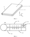
- the flip-type mobile phone 10 includes an outer housing 11, a rotating shaft 12, and an inner housing 13.
- An outer screen is mounted on the outer housing 11, and an inner screen is mounted on the inner housing 13.
- the housing in this application includes a display surface and a reverse surface of the display surface.
- the housing has two surfaces. One surface may display a user interface, and the other surface may integrate circuits to connect to and communicate with another module of the mobile phone.
- the outer screen and the inner screen may be considered as two screens.
- the outer screen and the inner screen may form an entire screen, that is, the outer screen and the inner screen may actually be an entire flexible screen, but when folded, the outer screen and the inner screen are visually located on the two housings and form two screens.
- the outer screen and the inner screen may be independent and are located on two housings connected by using the rotating shaft 12.
- the foldable terminal device provided in this embodiment of this application is applicable to both a flexible screen and a non-flexible screen, and a screen material is not limited in this application.
- FIG. 1 is a schematic form, and the mobile phone further includes another part or module, but is not shown in FIG. 1 . Because this application mainly relates to a locking apparatus for controlling opening and closing between the outer housing 11 and the inner housing 13 shown in FIG. 1, FIG. 1 shows only a part of the terminal device mainly involved in this application.
- FIG. 2 is a schematic diagram of another foldable terminal device in an unfolded mode.
- FIG. 2 is a schematic diagram of appearance of the electronic device at six different angles: a front surface, a back surface, a bottom surface, a top surface, a left surface, and a right surface.
- 14 in the front view is a flexible screen component of the electronic device.
- 15 and 16 in the rear view are housings of the electronic device, for example, a first housing and a second housing.
- a dashed-line box shows a bending area 17 of the electronic device.
- FIG. 3 is a schematic diagram of the foldable terminal device in a folded mode.
- the bending structure 17 deforms, and the first housing 15 and the second housing 16 are stacked.
- the bending structure 17 may be a known bending structure used on a foldable terminal. Details are not described herein.
- a component such as a common rotating shaft that can implement rotatable connection may also be used to perform the rotatable connection.
- the bending area 17 may be disposed longitudinally, and a flexible screen may be folded left and right along the longitudinally disposed bending area, as shown in FIG. 2 .
- the bending area 17 may be disposed horizontally, and the flexible screen may be folded up and down along the horizontally disposed bending area, as shown in FIG. 9 .
- a left screen when the foldable terminal device is unfolded, a left screen may be folded in a direction facing a right screen, or may be folded in a direction opposite to the right screen.
- the flexible screen component 14 shown in FIG. 3 is located on an outer surface of the foldable terminal device after folding is used for description. This is not limited in this application.
- FIG. 1 to FIG. 3 use an example in which the terminal device is a mobile phone.
- the terminal device in the technical solutions of the embodiments of this application may refer to user equipment, an access terminal, a user unit, a user station, a mobile station, a mobile console, a remote station, a remote terminal, a mobile device, a user terminal, a terminal, a wireless communications device, a user agent, or a user apparatus.
- the terminal device may alternatively be a cellular phone, a cordless phone, a session initiation protocol (session initiation protocol, SIP) phone, a wireless local loop (wireless local loop, WLL) station, a personal digital assistant (personal digital assistant, PDA), a handheld device having a wireless communication function, a computing device, another processing device connected to a wireless modem, a vehicle-mounted device, a wearable device, a terminal device in a future 5G network, or a terminal device in a future evolved public land mobile network (public land mobile network, PLMN).
- SIP session initiation protocol
- WLL wireless local loop
- PDA personal digital assistant
- PLMN public land mobile network
- the terminal device includes a hardware layer, an operating system layer running above the hardware layer, and an application layer running above the operating system layer.
- the hardware layer includes hardware such as a central processing unit (central processing unit, CPU), a memory management unit (memory management unit, MMU), and a memory (which is also referred to as a main memory).
- the operating system may be any one or more computer operating systems that implement service processing by using a process (process), for example, a Linux operating system, a Unix operating system, an Android operating system, an iOS operating system, or a Windows operating system.
- the application layer includes applications such as a browser, an address book, word processing software, and instant messaging software.
- aspects or features of this application may be implemented as a method, an apparatus or a product that uses standard programming and/or engineering technologies.
- the term "product" used in this application covers a computer program that can be accessed from any computer-readable component, carrier or medium.
- the computer-readable medium may include but is not limited to: a magnetic storage component (for example, a hard disk, a floppy disk, or a magnetic tape), an optical disc (for example, a compact disc (compact disc, CD), and a digital versatile disc (digital versatile disc, DVD)), a smart card and a flash memory component (for example, erasable programmable read-only memory (erasable programmable read-only memory, EPROM), a card, a stick, or a key drive).
- a magnetic storage component for example, a hard disk, a floppy disk, or a magnetic tape
- an optical disc for example, a compact disc (compact disc, CD), and a digital versatile disc (digital versatile disc, DVD)
- various storage media described in this specification may indicate one or more devices and/or other machine-readable media that are configured to store information.
- machine-readable media may include but is not limited to a radio channel, and various other media that can store, contain, and/or carry instructions and/or data.
- the foldable terminal device may have a folded mode and a bar-type mode.
- the folded mode may mean that one frame of the foldable terminal device approaches another frame of the foldable terminal device from a relatively far distance, and is sometimes referred to as a cover-closed mode.
- the bar-type mode may be, for example, an initial mode before the occurrence of the above-described "approaching" process, and may sometimes be referred to as a cover-opened mode.
- the foldable terminal device In the two different modes, relative positions of electronic elements in the foldable terminal device are different. In the folded mode and in the bar-type mode, the foldable terminal device sometimes has different use performance. Changing relative positions of antennas in the foldable terminal device usually causes a change in use performance of the antennas. This affects user experience.
- this application provides a foldable terminal device, to unify use performance of the foldable terminal device and improve user experience.
- FIG. 4 is a schematic structural diagram of a foldable terminal device 200 according to an embodiment of this application.
- the foldable terminal device 200 includes a first part 201 and a second part 202 that are foldable. It should be understood that, when the foldable terminal device 200 is in a folded mode, a frame of the first part 201 may be close to a frame of the second part 202, and the first part 201 and the second part 202 are configured to be folded.
- the first part 201 is configured with a first antenna element 210
- the second part 202 is configured with a second antenna element 220.
- the terminal device 200 further includes a first feed source 231 that feeds the first antenna element 210, so that the first antenna element 210 can operate in an operating frequency band.
- the second antenna element 220 is coupled to the first antenna element 210 for coupled feeding, so that the second antenna element 220 can operate in the operating frequency band of the first antenna element 210.
- first part 201 and the “second part 202" may be two components on the foldable terminal device 200, for example, may be a display 1 and a display 2, or may be a frame 1 and a frame 2.
- the "first part 201" and the “second part 202" may alternatively be two areas of the foldable terminal device 200, for example, may be a top area and a bottom area of the foldable terminal device 200, or for another example, may be an exposed area and an included area of the foldable terminal device 200.
- an “antenna element” is an entity module that has a function of receiving a signal or sending a signal.
- One antenna element may operate in one or more frequency bands.
- first antenna element 210 and the second antenna element 220 in the foldable terminal device 200 are not limited.
- the first antenna element 210 may be located at an earpiece end of the foldable terminal device 200, and the second antenna element 220 may be located at a microphone end of the foldable terminal device 200.
- the first antenna element 210 may be located at the microphone end of the foldable terminal device 200, and the second antenna element 220 may be located at the earpiece end of the foldable terminal device 200. It should be understood that, in this embodiment of this application, a position of the first antenna element 210 and a position of the second antenna element 220 may be exchanged.
- the first part 201 includes a first frame
- the second part 202 includes a second frame
- the first antenna element 210 is disposed around the first frame
- the second antenna element 220 is disposed around the second frame, and when the foldable terminal device 200 is folded, the first frame and the second frame are located on a same side of the foldable terminal device 200.
- FIG. 5 is a schematic diagram of the foldable terminal device 200 in a bar-type mode.
- the first antenna element 210 is disposed near the first frame on the left of the top of the foldable terminal device 200
- the second antenna element 220 is disposed near the second frame on the right of the top of the foldable terminal device 200.
- both the first frame and the second frame are located on the top of the foldable terminal device 200, that is, located on the same side of the foldable terminal device 200.
- FIG. 6 is a schematic diagram of the foldable terminal device 200 in a bar-type mode.
- the first antenna element 210 is disposed near the first frame on the left of the center of the foldable terminal device 200
- the second antenna element 220 is disposed near the second frame on the right of the center of the foldable terminal device 200.
- both the first frame and the second frame are located on the same side of the foldable terminal device 200.
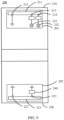
- FIG. 9 is a schematic diagram of the foldable terminal device 200 in a bar-type mode.
- the first antenna element 210 is disposed near the first frame on the top of the foldable terminal device 200
- the second antenna element 220 is disposed near the second frame on the bottom of the foldable terminal device 200.
- both the first frame and the second frame are located on the top of the foldable terminal device 200, that is, located on the same side of the foldable terminal device 200.
- FIG. 10 is a schematic diagram of the foldable terminal device 200 in a bar-type mode.
- the first antenna element 210 is disposed near the first frame on the left of the bottom of the foldable terminal device 200
- the second antenna element 220 is disposed near the second frame on the right of the bottom of the foldable terminal device 200.
- both the first frame and the second frame are located on the bottom of the foldable terminal device 200, that is, located on the same side of the foldable terminal device 200.
- the first frame and the second frame are located on the same side of the foldable terminal device 200.
- the first antenna element 210 is relatively close to the second antenna element 220, so that a coupling feeding effect is better.
- the first antenna element 210 and the second antenna element 220 are relatively close to the frames of the foldable terminal device 200, so that signals can be easily radiated.
- the first antenna element 210 and the second antenna element 220 may not be disposed at positions on the foldable terminal device 200 that are near the frames.
- Coupling feeding generally means that two circuit elements conduct electrical energy in a coupling manner.
- the dashed line in FIG. 4 shows that the first antenna element 210 is coupled to the second antenna element 220 for coupled feeding, that is, the first antenna element 210 conducts electrical energy to the second antenna element 220 in a coupling manner.
- “coupling feeding” may refer to implementing, in a coupling manner, feeding that meets a preset condition. For example, when the antenna is normally used, parameters such as coupling feeding efficiency and coupling feeding strength meet preset conditions.
- the first antenna element 210 is fed by the first feed source 231, so that the first antenna element 210 can operate in a frequency band 1.
- the second antenna element 220 is coupled to and fed by the first antenna element 210, so that the second antenna element 220 can operate in the frequency band 1.
- the first antenna element 210 is fed by the first feed source 231, so that the first antenna element 210 can operate in the frequency band 1, and the first antenna element 210 is further fed by another feed source, so that the first antenna element 210 can operate in a frequency band 2.
- the second antenna element 220 is coupled to and fed by the first antenna element 210, so that the second antenna element 220 can operate in the frequency band 1 or operate in the frequency band 2.
- the second antenna element 220 can also operate in another frequency band.
- the foldable terminal device 200 includes a feed source 1 that feeds the second antenna element 220, so that the second antenna element 220 can operate in a frequency band 3.
- the second antenna element 220 is coupled to and fed by the first antenna element 210, so that the second antenna element 220 can operate in the operating frequency band of the first antenna element 210.
- an operating frequency band of the second antenna element 220 there are a plurality of manners of implementing an operating frequency band of the second antenna element 220 to be the same as that of the first antenna element 210.
- an electronic element that can play a tuning function such as an inductor or a capacitor may be used to adjust the operating frequency band of the second antenna element 220 to be the same as that of the first antenna element 210.
- the manner of implementing the operating frequency band of the second antenna element 220 to be the same as that of the first antenna element 210 may be similar to that in the current technology. To avoid repetition, description is omitted herein.
- the operating frequency band of the first antenna element 210 may include, for example, a frequency band of 2.4 GHz to 2.5 GHz that is used for communication of wireless fidelity (wireless fidelity, WiFi), Bluetooth (bluetooth ® ), and the like.
- the operating frequency band of the first antenna element 210 may further include, for example, a near field communication (near field communication, NFC) frequency band of 13.56 MHz.
- the operating frequency band of the first antenna element 210 may further include, for example, frequency bands of 600 MHz to 960 MHz and 1700 MHz to 3500 MHz that are used for a high-speed data network (cellular) 2G, a high-speed data network 3G, and a high-speed data network 4G.
- the operating frequency band of the first antenna element 210 may further include an operating frequency band used for a future 5G network.
- the first antenna element 210 configured in the first part 201 may normally operate in a specific frequency band.
- the second part 202 is relatively close to the first part 201, and an electronic element disposed in the second part 202 affects an electronic element disposed in the first part 201.
- This application uses such impact in a way that the second antenna element 220 disposed in the second part 202 and the first antenna element 210 disposed in the first part 201 are coupled for feeding and operate in a same frequency band. In this way, signal interference caused by a distance change can be avoided, and use performance of antennas can be improved.
- first antenna element 210 and the second antenna element 220 operate in the NFC frequency band, a near field communication read-write (read-write) capability and a card emulation (card emulation) capability of the foldable terminal device 200 can be improved. Because the first antenna element 210 and the second antenna element 220 are not directly electrically connected by using a conducting wire, but are electrically connected in a coupling manner, existence of the second antenna element 220 does not additionally introduce a problem of wiring difficulty.
- the first antenna element 210 includes a first antenna radiator 211.
- the first antenna radiator 211 includes a first connection point 212 and a second connection point 213.
- the first connection point 212 of the first antenna radiator 211 is grounded, and the second connection point 213 of the second antenna radiator 221 is electrically connected to the first feed source 231.
- the second antenna element 220 includes a second antenna radiator 221 and a first tuning element, and the second antenna radiator 221 is configured to couple to the first antenna radiator 211 for coupled feeding when the foldable terminal device 200 is folded.
- the second antenna radiator 221 includes a third connection point 222 and a fourth connection point 223. Both the third connection point 222 of the second antenna radiator 221 and the fourth connection point 223 of the second antenna radiator 221 are grounded.
- the first tuning element is electrically connected between a ground and the third connection point 222 of the second antenna radiator 221, and is configured to adjust the operating frequency band of the second antenna element 220 to include the operating frequency band of the first antenna element 210.
- the first antenna element 210 of the foldable terminal device 200 includes the first antenna radiator 211 configured to receive or send a signal.
- the first antenna radiator 211 includes one or more connection points.
- the first connection point 212 of the first antenna radiator 211 is grounded, and the second connection point 213 of the first antenna radiator 211 is electrically connected to the first feed source 231, so that the first feed source 231 feeds the first antenna element 210. Therefore, an area of the first antenna radiator 211 from the first connection point 212 to the second connection point 213 can operate in an operating frequency band.
- the second antenna element 220 of the foldable terminal device 200 includes the second antenna radiator 221 configured to receive or send a signal.
- the second antenna radiator 221 includes one or more connection points.
- the third connection point 222 of the second antenna radiator 221 is grounded, the fourth connection point 223 of the second antenna radiator 221 is electrically connected to one end of a tuning element, and the other end of the tuning element is grounded.
- the second antenna radiator 221 is coupled to the first antenna radiator 211 for coupled feeding. Therefore, an area of the second antenna radiator 221 from the third connection point 222 to the fourth connection point 223 can operate in the operating frequency band of the first antenna radiator 211, so that the second antenna element 220 operates on the operating frequency band of the first antenna element 210.
- connection points of the first antenna radiator 211 may be used to indicate a connection position at which the first antenna radiator 211 is electrically connected to another element.
- connection points of the second antenna radiator 221 may be used to indicate a connection position at which the second antenna radiator 221 is electrically connected to another element.
- the foldable terminal device 200 may have another possible implementation.
- the foldable terminal device 200 further includes a second feed source 234.
- the first antenna element 210 is fed by the first feed source 231 and the second feed source 234.
- the first antenna element 210 includes the first antenna radiator 211.
- the first antenna radiator 211 includes the first connection point 212 and the second connection point 213.
- the first connection point 212 of the first antenna radiator 211 is electrically connected to the second feed source 234, and the second connection point 213 of the second antenna radiator 221 is electrically connected to the first feed source 231.
- the second antenna element 220 includes the second antenna radiator 221 and a first tuning element, and the second antenna radiator 221 is configured to couple to the first antenna radiator 211 for coupled feeding.
- the second antenna radiator 221 includes the third connection point 222 and the fourth connection point 223.
- the first tuning element is electrically connected between a ground and the third connection point 222 of the second antenna radiator 221, and is configured to adjust the operating frequency band of the second antenna element 220 to include the operating frequency band of the first antenna element 210.
- the foldable terminal device 200 further includes the second feed source 234.
- the first antenna element 210 is fed by the first feed source 231 and the second feed source 234.
- the first antenna element 210 includes the first antenna radiator 211 configured to receive or send a signal.
- the first antenna radiator 211 includes one or more connection points.
- the first connection point 212 of the first antenna radiator 211 is electrically connected to the second feed source 234, and the second connection point 213 of the first antenna radiator 211 is electrically connected to the first feed source 231, where the first feed source 231 and the second feed source 234 are two feed sources providing differential signals for the first antenna radiator together, so that the first feed source 231 and the second feed source 234 feed the first antenna element 210.
- the second antenna element 220 of the foldable terminal device 200 includes the second antenna radiator 221 configured to receive or send a signal.
- the second antenna radiator 221 includes one or more connection points.
- the third connection point 222 of the second antenna radiator 221 is grounded, the fourth connection point 223 of the second antenna radiator 221 is electrically connected to one end of a tuning element, and the other end of the tuning element is grounded.
- the second antenna radiator 221 is coupled to the first antenna radiator 211 for coupled feeding. Therefore, an area of the second antenna radiator 221 from the third connection point 222 to the fourth connection point 223 can operate in the operating frequency band of the first antenna radiator 211, so that the second antenna element 220 operates on the operating frequency band of the first antenna element 210.
- distances from most point positions of the area of the first antenna radiator 211 from the first connection point 212 to the second connection point 213 to the area of the second antenna radiator 221 from the third connection point 222 to the fourth connection point 223 should be as close as possible.
- distances from most point positions of the area of the second antenna radiator 221 from the third connection point 222 to the fourth connection point 223 to the area of the first antenna radiator 211 from the first connection point 212 to the second connection point 213 should be as close as possible.
- a distance between the first connection point 212 of the first antenna radiator 211 and the third connection point 222 of the second antenna radiator 221 is less than a first preset threshold, and a distance between the second connection point 213 of the first antenna radiator 211 and the fourth connection point 223 of the second antenna radiator 221 is less than a second preset threshold; or a distance between the first connection point 212 of the first antenna radiator 211 and the fourth connection point 223 of the second antenna radiator 221 is less than the first preset threshold, and a distance between the second connection point 213 of the first antenna radiator 211 and the third connection point 222 of the second antenna radiator 221 is less than the second preset threshold.
- both the first preset threshold and the second preset threshold may be preset based on a specific situation. This is not limited in this embodiment of this application.
- the first antenna radiator 211 and the second antenna radiator 221 are disposed in parallel or approximately parallel on the foldable terminal device 200.
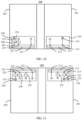
- the foldable terminal device 200 is viewed from a side surface of the foldable terminal device 200 and from an angle at which a longest side of the first antenna radiator 211 or the second antenna radiator 221 can be observed, as shown in FIG. 7 and FIG. 8.
- FIG. 7 shows a case in which a distance between the first connection point 212 of the first antenna radiator 211 and the third connection point 222 of the second antenna radiator 221 is less than a first preset threshold, and a distance between the second connection point 213 of the first antenna radiator 211 and the fourth connection point 223 of the second antenna radiator 221 is less than a second preset threshold.
- the first connection point 212 of the first antenna radiator 211 is correspondingly disposed right above the third connection point 222 of the second antenna radiator 221, and the second connection point 213 of the first antenna radiator 211 is correspondingly disposed right above the fourth connection point 223 of the second antenna radiator 221.
- a projection area of the area of the first antenna radiator 211 from the first connection point 212 to the second connection point 213 on the second antenna radiator 221 coincides with the area of the second antenna radiator 221 from the third connection point 222 to the fourth connection point 223.
- first connection point 212 of the first antenna radiator 211 is aligned with the third connection point 222 of the second antenna radiator 221
- second connection point 213 of the first antenna radiator 211 is aligned with the fourth connection point 223 of the second antenna radiator 221.
- FIG. 8 shows a case in which a distance between the first connection point 212 of the first antenna radiator 211 and the fourth connection point 223 of the second antenna radiator 221 is less than a first preset threshold, and a distance between the second connection point 213 of the first antenna radiator 211 and the third connection point 222 of the second antenna radiator 221 is less than a second preset threshold.
- the first connection point 212 of the first antenna radiator 211 is correspondingly disposed right above the fourth connection point 223 of the second antenna radiator 221, and the second connection point 213 of the first antenna radiator 211 is correspondingly disposed right above the third connection point 222 of the second antenna radiator 221.
- a projection area of the area of the first antenna radiator 211 from the first connection point 212 to the second connection point 213 on the second antenna radiator 221 coincides with an area of the second antenna radiator 221 from the fourth connection point 223 to the third connection point 222.
- the first connection point 212 of the first antenna radiator 211 is aligned with the fourth connection point 223 of the second antenna radiator 221
- the second connection point 213 of the first antenna radiator 211 is aligned with the third connection point 222 of the second antenna radiator 221.
- the first antenna element 210 is fed by the first feed source 231 and operates on a first frequency band.
- the foldable terminal device 200 further includes: a third feed source 232, where the first antenna element 210 is fed by the third feed source 232 and operates on a second frequency band; a first filtering element, electrically connected between the first feed source 231 and the first antenna element 210, and configured to filter a signal of the second frequency band; and a second filtering element, electrically connected between the third feed source 232 and the first antenna element 210, and configured to filter a signal of the first frequency band.
- the first antenna element 210 can multiplex a plurality of antennas, so as to operate in a plurality of frequency bands.
- the first feed source 231 provides a feed for the first antenna element 210, so that the first antenna element 210 can operate in the first frequency band.
- the first antenna element 210 further includes a fifth connection point 214
- the foldable terminal device 200 further includes the third feed source 232 electrically connected to the fifth connection point 214 of the first antenna element 210.
- the third feed source 232 provides a feed for the first antenna element 210, so that the first antenna element 210 can operate in the second frequency band.
- An area of the first antenna element 210 from the first connection point 212 to the second connection point 213 may be configured to radiate a signal of the first frequency band
- an area of the first antenna element 210 from the first connection point 212 to the fifth connection point 214 may be configured to radiate a signal of the second frequency band.
- the first filtering element is connected in series on a connection path on which the second connection point 213 of the first antenna element 210 is electrically connected to the first feed source 231, and the first filtering element is configured to filter the signal of the second frequency band; and the second filtering element is connected in series on a connection path on which the fifth connection point 214 of the first antenna element 210 is electrically connected to the third feed source 232, and the second filtering element is configured to filter the signal of the first frequency band.
- the filtering element in this application may be an element such as a capacitor or an inductor, or may be a filtering apparatus configured with a plurality of elements.
- the first frequency band is a low frequency band, for example, may be 10 MHz to 50 MHz
- the second frequency band is a high frequency band, for example, may be more than 600 MHz
- the first filtering element may be an inductor
- the second filtering element may be a capacitor.
- the second antenna element 220 may be coupled to the first antenna element 210 for coupled feeding, and operates on the first frequency band or the second frequency band.
- the foldable terminal device 200 further includes: a second tuning element 241, electrically connected to the first antenna element 210, and configured to adjust the second frequency band.
- the second tuning element 241 is electrically connected to the first antenna element 210, and is configured to adjust the second frequency band.
- the second frequency band may be adjusted from the high frequency band to a medium-high frequency band.
- the second antenna element 220 is coupled to and fed by the first antenna element 210 and operates on a third frequency band.
- the foldable terminal device 200 further includes: a fourth feed source 233, a third filtering element, and a fourth filtering element.
- the second antenna element 220 is fed by the fourth feed source 233 and operates on a fourth frequency band.
- the third filtering element is electrically connected between a ground and the second antenna element 220, and is configured to filter a signal of the fourth frequency band.
- the fourth filtering element is electrically connected between the fourth feed source 233 and the second antenna element 220, and is configured to filter a signal of the third frequency band.
- the first antenna element 210 can multiplex a plurality of antennas, so as to operate in a plurality of frequency bands.
- the first antenna element 210 provides a feed for the second antenna element 220, so that the second antenna element 220 can operate in the third frequency band.
- the second antenna element 220 further includes a sixth connection point 224, and the foldable connection device further includes the fourth feed source 233 electrically connected to the sixth connection point 224 of the second antenna element 220.
- the fourth feed source 233 provides a feed for the second antenna element 220, so that the second antenna element 220 can operate in the fourth frequency band.
- An area of the second antenna element 220 from the third connection point 222 to the fourth connection point 223 may be configured to radiate a signal of the third frequency band
- an area of the second antenna element 220 from the third connection point 222 to the sixth connection point 224 may be configured to radiate a signal of the fourth frequency band.
- the third filtering element is connected in series on a connection path on which the fourth connection point 223 of the second antenna element 220 is electrically connected to a ground, and the third filtering element is configured to filter the signal of the fourth frequency band; and the fourth filtering element is connected in series on a connection path on which the sixth connection point 224 of the second antenna element 220 is electrically connected to the third feed source 232, and the fourth filtering element is configured to filter the signal of the third frequency band.
- FIG. 10 is used as an example, if the third frequency band is a low frequency band, for example, may be 10 MHz to 50 MHz, and the fourth frequency band is a high frequency band, for example, may be more than 600 MHz, the third filtering element may be an inductor, and the fourth filtering element may be a capacitor.
- the first tuning element may be configured to not only tune an operating frequency band of the second antenna element to include an operating frequency band of the first antenna element, but also filter the fourth frequency band.
- the first tuning element 240 shown in FIG. 10 may be the third filtering element.
- the second antenna element 220 can operate in the operating frequency band of the first antenna element 210 and the fourth frequency band.
- the foldable terminal device 200 further includes: a third tuning element 242, electrically connected to the second antenna element 220, and configured to adjust the fourth frequency band.
- the third tuning element 242 is electrically connected to the second antenna element 220, and is configured to adjust the fourth frequency band.
- the fourth frequency band may be adjusted from the high frequency band to a medium-high frequency band.
- FIG. 11 is a foldable terminal device 200 according to this application.
- the first feed source 231 provides a feed for the first antenna element 210, so that the first antenna element 210 can operate in the first frequency band.
- the first antenna element 210 further includes a fifth connection point 214, and the foldable terminal device 200 further includes the third feed source 232 electrically connected to the fifth connection point 214 of the first antenna element 210.
- the third feed source 232 provides a feed for the first antenna element 210, so that the first antenna element 210 can operate in the second frequency band.
- An area of the first antenna element 210 from the first connection point 212 to the second connection point 213 may be configured to radiate a signal of the first frequency band
- an area of the first antenna element 210 from the first connection point 212 to the fifth connection point 214 may be configured to radiate a signal of the second frequency band.
- the first filtering element is connected in series on a connection path on which the second connection point 213 of the first antenna element 210 is electrically connected to the first feed source 231, and the first filtering element is configured to filter the signal of the second frequency band; and the second filtering element is connected in series on a connection path on which the fifth connection point 214 of the first antenna element 210 is electrically connected to the third feed source 232, and the second filtering element is configured to filter the signal of the first frequency band.
- the first antenna element 210 provides a feed for the second antenna element 220, so that the second antenna element 220 can operate in the third frequency band.
- the second antenna element 220 further includes a sixth connection point 224
- the foldable terminal device further includes the fourth feed source 233 electrically connected to the sixth connection point 224 of the second antenna element 220.
- the fourth feed source 233 provides a feed for the second antenna element 220, so that the second antenna element 220 can operate in the fourth frequency band.
- An area of the second antenna element 220 from the third connection point 222 to the fourth connection point 223 may be configured to radiate a signal of the third frequency band
- an area of the second antenna element 220 from the third connection point 222 to the sixth connection point 224 may be configured to radiate a signal of the fourth frequency band.
- the third filtering element is connected in series on a connection path on which the fourth connection point 223 of the second antenna element 220 is electrically connected to a ground, and the third filtering element is configured to filter the signal of the fourth frequency band; and the fourth filtering element is connected in series on a connection path on which the sixth connection point 224 of the second antenna element 220 is electrically connected to the third feed source 232, and the fourth filtering element is configured to filter the signal of the third frequency band.
- the disclosed system, apparatus, and method may be implemented in other manners.
- the described apparatus embodiment is merely an example.
- the unit division is merely logical function division and may be other division in actual implementation.
- a plurality of units or components may be combined or integrated into another system, or some features may be ignored or not performed.
- the displayed or discussed mutual couplings or direct couplings or communication connections may be implemented through some interfaces.
- the indirect couplings or communication connections between the apparatuses or units may be implemented in electronic, mechanical, or other forms.
- the units described as separate parts may or may not be physically separate, and parts displayed as units may or may not be physical units, may be located in one position, or may be distributed on a plurality of network units. Some or all of the units may be selected based on actual requirements to achieve the objectives of the solutions of the embodiments.
- function units in the embodiments of this application may be integrated into one processing unit, or each of the units may exist alone physically, or two or more units are integrated into one unit.
- the functions When the functions are implemented in the form of a software function unit and sold or used as an independent product, the functions may be stored in a computer-readable storage medium. Based on such an understanding, the technical solutions of this application essentially, or the part contributing to the prior art, or some of the technical solutions may be implemented in a form of a software product.
- the computer software product is stored in a storage medium, and includes several instructions for instructing a computer device (which may be a personal computer, a server, or a network device) to perform all or some of the steps of the methods described in the embodiments of this application.
- the foregoing storage medium includes: any medium that can store program code, such as a USB flash drive, a removable hard disk, a read-only memory (read-only memory, ROM), a random access memory (random access memory, RAM), a magnetic disk, or an optical disc.
- program code such as a USB flash drive, a removable hard disk, a read-only memory (read-only memory, ROM), a random access memory (random access memory, RAM), a magnetic disk, or an optical disc.
Landscapes
- Engineering & Computer Science (AREA)
- Signal Processing (AREA)
- Computer Networks & Wireless Communication (AREA)
- Physics & Mathematics (AREA)
- Electromagnetism (AREA)
- Telephone Set Structure (AREA)
- Support Of Aerials (AREA)
- Details Of Aerials (AREA)
Description
- This application relates to the field of electronic devices, and more specifically, to a foldable terminal device.
- As usage scenarios of a terminal device continuously increase, structure types of the terminal device begin to increase. The most common structure types are bar-type terminal devices and foldable terminal devices. Designs of antennas in the terminal device vary according to the structure types of the terminal device.
- The foldable terminal device has two parts that are relatively movable (for example, relatively sliding and relatively rotating). For example, one part 1 may rotate relative to a side of another part 2. For another example, one part may slide on a surface of another part. Therefore, the foldable terminal device may have a bar-type mode in which a cover is opened and a folded mode in which a cover is closed. For example, the foldable terminal device includes the part 1 and the part 2. After the part 1 rotates relative to one end of the part 2, a surface of the part 1 is in contact with and coincides with a surface of the part 2, and the two surfaces cannot be exposed. In this case, the foldable terminal device is in the folded mode in which the cover is closed. However, after the part 1 rotates relative to one end of the part 2, the two surfaces are no longer in contact and are exposed. In this case, the foldable terminal device may be in the bar-type mode in which the cover is opened. For another example, the foldable terminal device includes a part 3 and a part 4. After the part 3 slides on the part 4, a projection area that is of a surface of the part 3 and that is on the part 4 coincides with a surface of the part 4. In this case, the foldable terminal device is in the folded mode in which the cover is closed. However, after the part 3 slides on the part 4, the projection area no longer coincides with the surface of the part 4. In this case, the foldable terminal device may be in the bar-type mode in which the cover is opened.
- However, in the two modes, use performance of antennas that are of the two relatively movable parts and that have different relative positions and a same operating frequency band is likely to change. This affects stability of antenna signals. To ensure stable use of an antenna in the two modes, a plurality of antennas with a same operating frequency band usually need to be disposed on the two relatively movable parts of the terminal device. Therefore, antenna arrangement and connection methods become complex.
-
CN 109361062 A discloses a mobile terminal which solves the problem that the radiation capability of the antenna is poor when the mobile terminal is in the folded state. -
US 2017/0110786 A1 discloses an electronic device that is configurable to be transitioned from a first operating mode having a first form factor to a second operating mode having a second form factor. -
EP 3 920 327 A1 discloses an antenna apparatus which can be used in an electronic device having a flexible display which can be bent at a rotating shaft. The flexible display includes a primary screen and a secondary screen, and the primary screen and the secondary screen are connected by using the rotating shaft. - This application provides a foldable terminal device, to provide a foldable terminal device with a simple structure and high antenna performance.
- According to a first aspect, a foldable terminal device as defined in claim 1 is provided. According to a second aspect, a foldable terminal device as defined in claim 2 is provided.
- In these aspects of this application, when the foldable terminal device is in a folded mode, the second part is relatively close to the first part, and an electronic element disposed in the second part affects an electronic element disposed in the first part. This application uses such impact in a way that the second antenna element disposed in the second part and the first antenna element disposed in the first part are coupled for feeding and operate in a same frequency band. In this way, signal interference caused by a distance change can be avoided, and use performance of antennas can be improved. Because the first antenna element and the second antenna element are not directly electrically connected by using a conducting wire, but are electrically connected in a coupling manner, existence of the second antenna element does not additionally introduce a problem of wiring difficulty.
- With reference to the first and second aspects, the first antenna element includes: a first antenna radiator, including a first connection point and a second connection point. The first connection point of the first antenna radiator is grounded, and the second connection point of the first antenna radiator is electrically connected to the first feed source. The second antenna element includes: a second antenna radiator, configured to couple to the first antenna radiator for coupled feeding when the foldable terminal device is folded, and including a third connection point and a fourth connection point, where both the third connection point of the second antenna radiator and the fourth connection point of the second antenna radiator are grounded, and a first tuning element, electrically connected between a ground and the third connection point of the second antenna radiator, and configured to adjust the operating frequency band of the second antenna element to include the operating frequency band of the first antenna element.
- When the first antenna element and the second antenna element are coupled for feeding, the operating frequency band of the second antenna element may be slightly different from the operating frequency band of the first antenna element, and a coincidence degree between the operating frequency band of the second antenna element and the operating frequency band of the first antenna element does not meet a requirement. The operating frequency band of the second antenna element is adjusted by using a tuning element, so that coupling feeding efficiency between the first antenna radiator and the second antenna radiator can be improved.
- With reference to the first and second aspects, when the foldable terminal device is folded, a distance between the first connection point of the first antenna radiator and the third connection point of the second antenna radiator is less than a first preset threshold, and a distance between the second connection point of the first antenna radiator and the fourth connection point of the second antenna radiator is less than a second preset threshold; or a distance between the first connection point of the first antenna radiator and the fourth connection point of the second antenna radiator is less than the first preset threshold, and a distance between the second connection point of the first antenna radiator and the third connection point of the second antenna radiator is less than the second preset threshold.
- A distance between the first antenna radiator and the second antenna radiator is relatively close, so that coupling feeding efficiency between the first antenna radiator and the second antenna radiator can be improved.
- With reference to the first and second aspects, the first part includes a first frame, and the second part includes a second frame; and the first antenna element is disposed around the first frame, the second antenna element is disposed around the second frame, and when the foldable terminal device is folded, the first frame and the second frame are located on a same side of the foldable terminal device.
- The first antenna element and the second antenna element are disposed on the same side of the foldable terminal device, so that coupling feeding efficiency between the first antenna radiator and the second antenna radiator can be improved.
- With reference to the first and second aspects, the first antenna radiator is the first frame, and the second antenna radiator is the second frame.
- By using a frame as an antenna radiator, a structure of the foldable terminal device can be simplified.
- A distance between the first antenna radiator and the second antenna radiator is relatively close, so that coupling feeding efficiency between the first antenna radiator and the second antenna radiator can be improved.
- The first antenna element and the second antenna element are disposed on the same side of the foldable terminal device, so that coupling feeding efficiency between the first antenna radiator and the second antenna radiator can be improved.
- With reference to the first and second aspects, the first antenna radiator is the first frame, and the second antenna radiator is the second frame.
- By using a frame as an antenna radiator, a structure of the foldable terminal device can be simplified.
- With reference to the first and second aspects, the first antenna element is fed by the first feed source and operates on a first frequency band. The foldable terminal device further includes: a third feed source, where the first antenna element is fed by the third feed source and operates on a second frequency band; a first filtering element, electrically connected between the first feed source and the first antenna element, and configured to filter a signal of the second frequency band; and a second filtering element, electrically connected between the third feed source and the first antenna element, and configured to filter a signal of the first frequency band.
- A filter is configured to filter a signal of a specific frequency band, to avoid interference between different frequency bands, so that the first antenna element can operate in a plurality of frequency bands.
- With reference to the first aspect, in some implementations of the first aspect, the foldable terminal device further includes: a second tuning element, electrically connected to the first antenna element, and configured to adjust the second frequency band.
- A tuning element may enable the first antenna element to multiplex a plurality of antennas, so that the first antenna element can operate in a plurality of frequency bands.
- With reference to the first and second aspects, the second antenna element is coupled to and fed by the first antenna element and operates on a third frequency band, and the third frequency band is the same as the first frequency band. The foldable terminal device further includes: a fourth feed source, where the second antenna element is fed by the fourth feed source and operates on a fourth frequency band; a third filtering element, electrically connected between the ground and the second antenna element, and configured to filter a signal of the fourth frequency band; and a fourth filtering element, electrically connected between the fourth feed source and the second antenna element, and configured to filter a signal of the third frequency band.
- The filter is configured to filter a signal of a specific frequency band, to avoid interference between different frequency bands, so that the second antenna element can operate in a plurality of frequency bands.
- With reference to the first and second aspects, the foldable terminal device further includes: a third tuning element, electrically connected to the second antenna element, and configured to adjust the fourth frequency band.
- The tuning element may enable the second antenna element to multiplex a plurality of antennas, so that the second antenna element can operate in a plurality of frequency bands.
- With reference to the first and second aspects, when the foldable terminal device is unfolded, the first antenna element is fed by the first feed source and operates on the first frequency band; and the second antenna element does not operate or operates on another frequency band different from the first frequency band.
- When a distance between the first antenna element and the second antenna element is relatively long, the first antenna element may operate independently, and use performance of the foldable terminal device is not changed.
- With reference to the first and second aspects, the operating frequency band of the first antenna element includes an operating frequency band of a near field communication NFC antenna.
- Both a first part side and a second part side of the foldable terminal device may be used in an NFC application scenario, thereby improving use performance of the foldable terminal device.
- Because two movable parts of the foldable terminal device may move relatively, an antenna position in the foldable terminal device may also move relatively. When the foldable terminal device is in an bar-type mode, a distance between antennas is relatively long, and impact between the antennas is relatively small. However, when the foldable terminal device is in a folded mode, the distance between the antennas is relatively close, and the impact between the antennas (for example, interference between the antennas and impact on antenna performance) cannot be ignored. Antennas with a same operating frequency band are disposed on the two movable parts of the foldable terminal device, and the antennas may be fed by a same feed source through a feeding line. This introduces a problem of complex arrangement of feeding lines. This application uses such impact in a way that the second antenna element disposed in the second part and the first antenna element disposed in the first part are coupled for feeding and operate in a same frequency band. In this way, signal interference caused by a distance change can be avoided, and use performance of antennas can be improved. Because the first antenna element and the second antenna element are not directly electrically connected by using a conducting wire, but are electrically connected in a coupling manner, existence of the second antenna element does not additionally introduce a problem of wiring difficulty.
-
-
FIG. 1 is a schematic diagram of a foldable terminal device; -
FIG. 2 is a schematic diagram of a foldable terminal device; -
FIG. 3 is a schematic diagram of a foldable terminal device; -
FIG. 4 is a schematic structural diagram of a foldable terminal device according to an embodiment of this application; -
FIG. 5 is a schematic structural diagram of a foldable terminal device according to an embodiment of this application useful for understanding the invention; -
FIG. 6 is a schematic structural diagram of a foldable terminal device according to an embodiment of this application useful for understanding the invention; -
FIG. 7 is a schematic view diagram of a foldable terminal device according to an embodiment of this application; -
FIG. 8 is a schematic view diagram of a foldable terminal device according to an embodiment of this application; -
FIG. 9 is a schematic structural diagram of a foldable terminal device according to an embodiment of this application forming part of the claimed invention; -
FIG. 10 is a schematic structural diagram of a foldable terminal device according to an embodiment of this application forming part of the claimed invention; and -
FIG. 11 is a schematic structural diagram of a foldable terminal device according to an embodiment of this application forming part of the claimed invention. - The following describes technical solutions of this application with reference to the accompanying drawings.
- Terms used in the following embodiments are merely intended to describe specific embodiments, but are not intended to limit this application. Terms "one", "a", "the", "the foregoing", "this", and "the one" of singular forms used in this specification and the appended claims of this application are also intended to include plural forms like "one or more", unless otherwise specified in the context clearly. It should be further understood that, in the embodiments of this application, "one or more" means one, two, or more. In addition, "and/or" describes an association relationship between associated objects, and indicates that three relationships may exist. For example, A and/or B may indicate the following cases: only A exists, both A and B exist, and only B exists, where A and B may be singular or plural. The character "/" generally indicates an "or" relationship between the associated objects.
- Reference to "an embodiment", "some embodiments", or the like described in this specification indicates that one or more embodiments of this application include a specific feature, structure, or characteristic described with reference to the embodiments. Therefore, in this specification, statements, such as "in an embodiment", "in some embodiments", "in some other embodiments", and "in other embodiments", that appear at different places do not necessarily mean referring to a same embodiment, instead, the statements mean referring to "one or more but not all of the embodiments", unless otherwise specifically emphasized in other ways. Terms "include", "comprise", "have", and variants of the terms all mean "include but are not limited to", unless otherwise specifically emphasized in other ways.
- The following describes specific implementations of the embodiments of this application in more detail with reference to specific examples. It should be noted that the examples below are merely intended to help a person skilled in the art understand the embodiments of this application, instead of limiting the embodiments of this application to a specific value or a specific scenario shown in the example.
- The foldable terminal device provided in this embodiment of this application may be a further improvement on the basis of an existing foldable terminal device. Generally, one outer frame of the foldable terminal device may approach another outer frame of the foldable terminal device from a relatively far distance. The foldable terminal device usually includes a slide-type terminal device and a flip-type terminal device. A common foldable terminal device in daily life includes a foldable mobile phone.
- A flip-type mobile phone is used as an example. As shown in
FIG. 1 , the flip-typemobile phone 10 includes anouter housing 11, a rotatingshaft 12, and aninner housing 13. An outer screen is mounted on theouter housing 11, and an inner screen is mounted on theinner housing 13. - It should be understood that the housing in this application includes a display surface and a reverse surface of the display surface. In other words, the housing has two surfaces. One surface may display a user interface, and the other surface may integrate circuits to connect to and communicate with another module of the mobile phone.
- Optionally, when the
outer housing 11 and theinner housing 13 are in a mode in which the flip-typemobile phone 10 is not flipped open (that is, the outer screen and the inner screen are folded to each other), the outer screen and the inner screen may be considered as two screens. When the flip-typemobile phone 10 is flipped open (that is, the outer screen and the inner screen are not folded to each other), the outer screen and the inner screen may form an entire screen, that is, the outer screen and the inner screen may actually be an entire flexible screen, but when folded, the outer screen and the inner screen are visually located on the two housings and form two screens. - Optionally, regardless of a mode of the flip-type
mobile phone 10, the outer screen and the inner screen may be independent and are located on two housings connected by using the rotatingshaft 12. - It should be understood that the foldable terminal device provided in this embodiment of this application is applicable to both a flexible screen and a non-flexible screen, and a screen material is not limited in this application.
- It should be further understood that
FIG. 1 is a schematic form, and the mobile phone further includes another part or module, but is not shown inFIG. 1 . Because this application mainly relates to a locking apparatus for controlling opening and closing between theouter housing 11 and theinner housing 13 shown inFIG. 1, FIG. 1 shows only a part of the terminal device mainly involved in this application. -
FIG. 2 is a schematic diagram of another foldable terminal device in an unfolded mode.FIG. 2 is a schematic diagram of appearance of the electronic device at six different angles: a front surface, a back surface, a bottom surface, a top surface, a left surface, and a right surface. 14 in the front view is a flexible screen component of the electronic device. 15 and 16 in the rear view are housings of the electronic device, for example, a first housing and a second housing. A dashed-line box shows a bendingarea 17 of the electronic device. -
FIG. 3 is a schematic diagram of the foldable terminal device in a folded mode. As shown inFIG. 3 , when the two housings rotate to be in the folded mode (an angle is 0 degrees), the bendingstructure 17 deforms, and thefirst housing 15 and thesecond housing 16 are stacked. The bendingstructure 17 may be a known bending structure used on a foldable terminal. Details are not described herein. In addition, when thefirst housing 15 is rotatably connected to thesecond housing 16, a component such as a common rotating shaft that can implement rotatable connection may also be used to perform the rotatable connection. - It should be understood that, for the foldable terminal device, the bending
area 17 may be disposed longitudinally, and a flexible screen may be folded left and right along the longitudinally disposed bending area, as shown inFIG. 2 . Alternatively, the bendingarea 17 may be disposed horizontally, and the flexible screen may be folded up and down along the horizontally disposed bending area, as shown inFIG. 9 . - It should be further understood that, when the foldable terminal device is unfolded, a left screen may be folded in a direction facing a right screen, or may be folded in a direction opposite to the right screen. In the description of this embodiment of this application, an example in which the
flexible screen component 14 shown inFIG. 3 is located on an outer surface of the foldable terminal device after folding is used for description. This is not limited in this application. - It should be further understood that
FIG. 1 to FIG. 3 use an example in which the terminal device is a mobile phone. Actually, the terminal device in the technical solutions of the embodiments of this application may refer to user equipment, an access terminal, a user unit, a user station, a mobile station, a mobile console, a remote station, a remote terminal, a mobile device, a user terminal, a terminal, a wireless communications device, a user agent, or a user apparatus. The terminal device may alternatively be a cellular phone, a cordless phone, a session initiation protocol (session initiation protocol, SIP) phone, a wireless local loop (wireless local loop, WLL) station, a personal digital assistant (personal digital assistant, PDA), a handheld device having a wireless communication function, a computing device, another processing device connected to a wireless modem, a vehicle-mounted device, a wearable device, a terminal device in a future 5G network, or a terminal device in a future evolved public land mobile network (public land mobile network, PLMN). This is not limited in the embodiments of this application. - In the embodiments of this application, the terminal device includes a hardware layer, an operating system layer running above the hardware layer, and an application layer running above the operating system layer. The hardware layer includes hardware such as a central processing unit (central processing unit, CPU), a memory management unit (memory management unit, MMU), and a memory (which is also referred to as a main memory). The operating system may be any one or more computer operating systems that implement service processing by using a process (process), for example, a Linux operating system, a Unix operating system, an Android operating system, an iOS operating system, or a Windows operating system. The application layer includes applications such as a browser, an address book, word processing software, and instant messaging software.
- In addition, aspects or features of this application may be implemented as a method, an apparatus or a product that uses standard programming and/or engineering technologies. The term "product" used in this application covers a computer program that can be accessed from any computer-readable component, carrier or medium. For example, the computer-readable medium may include but is not limited to: a magnetic storage component (for example, a hard disk, a floppy disk, or a magnetic tape), an optical disc (for example, a compact disc (compact disc, CD), and a digital versatile disc (digital versatile disc, DVD)), a smart card and a flash memory component (for example, erasable programmable read-only memory (erasable programmable read-only memory, EPROM), a card, a stick, or a key drive). In addition, various storage media described in this specification may indicate one or more devices and/or other machine-readable media that are configured to store information. The term "machine-readable media" may include but is not limited to a radio channel, and various other media that can store, contain, and/or carry instructions and/or data.
- The foldable terminal device may have a folded mode and a bar-type mode. The folded mode may mean that one frame of the foldable terminal device approaches another frame of the foldable terminal device from a relatively far distance, and is sometimes referred to as a cover-closed mode. The bar-type mode may be, for example, an initial mode before the occurrence of the above-described "approaching" process, and may sometimes be referred to as a cover-opened mode.
- In the two different modes, relative positions of electronic elements in the foldable terminal device are different. In the folded mode and in the bar-type mode, the foldable terminal device sometimes has different use performance. Changing relative positions of antennas in the foldable terminal device usually causes a change in use performance of the antennas. This affects user experience.
- To resolve the foregoing disadvantage, this application provides a foldable terminal device, to unify use performance of the foldable terminal device and improve user experience.
-
FIG. 4 is a schematic structural diagram of a foldableterminal device 200 according to an embodiment of this application. The foldableterminal device 200 includes afirst part 201 and asecond part 202 that are foldable. It should be understood that, when the foldableterminal device 200 is in a folded mode, a frame of thefirst part 201 may be close to a frame of thesecond part 202, and thefirst part 201 and thesecond part 202 are configured to be folded. - The
first part 201 is configured with afirst antenna element 210, and thesecond part 202 is configured with asecond antenna element 220. Theterminal device 200 further includes afirst feed source 231 that feeds thefirst antenna element 210, so that thefirst antenna element 210 can operate in an operating frequency band. - When the foldable
terminal device 200 is folded, thesecond antenna element 220 is coupled to thefirst antenna element 210 for coupled feeding, so that thesecond antenna element 220 can operate in the operating frequency band of thefirst antenna element 210. - It should be understood that the "
first part 201" and the "second part 202" may be two components on the foldableterminal device 200, for example, may be a display 1 and a display 2, or may be a frame 1 and a frame 2. The "first part 201" and the "second part 202" may alternatively be two areas of the foldableterminal device 200, for example, may be a top area and a bottom area of the foldableterminal device 200, or for another example, may be an exposed area and an included area of the foldableterminal device 200. - In this embodiment of this application, an "antenna element" is an entity module that has a function of receiving a signal or sending a signal. One antenna element may operate in one or more frequency bands.
- In this embodiment of this application, specific positions of the
first antenna element 210 and thesecond antenna element 220 in the foldableterminal device 200 are not limited. For example, thefirst antenna element 210 may be located at an earpiece end of the foldableterminal device 200, and thesecond antenna element 220 may be located at a microphone end of the foldableterminal device 200. Alternatively, thefirst antenna element 210 may be located at the microphone end of the foldableterminal device 200, and thesecond antenna element 220 may be located at the earpiece end of the foldableterminal device 200. It should be understood that, in this embodiment of this application, a position of thefirst antenna element 210 and a position of thesecond antenna element 220 may be exchanged. - Optionally, the
first part 201 includes a first frame, and thesecond part 202 includes a second frame; and thefirst antenna element 210 is disposed around the first frame, thesecond antenna element 220 is disposed around the second frame, and when the foldableterminal device 200 is folded, the first frame and the second frame are located on a same side of the foldableterminal device 200. -
FIG. 5 is a schematic diagram of the foldableterminal device 200 in a bar-type mode. Thefirst antenna element 210 is disposed near the first frame on the left of the top of the foldableterminal device 200, and thesecond antenna element 220 is disposed near the second frame on the right of the top of the foldableterminal device 200. When the foldableterminal device 200 is folded along a bendable middle area, both the first frame and the second frame are located on the top of the foldableterminal device 200, that is, located on the same side of the foldableterminal device 200. -
FIG. 6 is a schematic diagram of the foldableterminal device 200 in a bar-type mode. Thefirst antenna element 210 is disposed near the first frame on the left of the center of the foldableterminal device 200, and thesecond antenna element 220 is disposed near the second frame on the right of the center of the foldableterminal device 200. When the foldableterminal device 200 is folded along the bendable middle area, both the first frame and the second frame are located on the same side of the foldableterminal device 200. -
FIG. 9 is a schematic diagram of the foldableterminal device 200 in a bar-type mode. Thefirst antenna element 210 is disposed near the first frame on the top of the foldableterminal device 200, and thesecond antenna element 220 is disposed near the second frame on the bottom of the foldableterminal device 200. When the foldableterminal device 200 is folded along the bendable middle area, both the first frame and the second frame are located on the top of the foldableterminal device 200, that is, located on the same side of the foldableterminal device 200. -
FIG. 10 is a schematic diagram of the foldableterminal device 200 in a bar-type mode. Thefirst antenna element 210 is disposed near the first frame on the left of the bottom of the foldableterminal device 200, and thesecond antenna element 220 is disposed near the second frame on the right of the bottom of the foldableterminal device 200. When the foldableterminal device 200 is folded along the bendable middle area, both the first frame and the second frame are located on the bottom of the foldableterminal device 200, that is, located on the same side of the foldableterminal device 200. - When the foldable
terminal device 200 is folded, the first frame and the second frame are located on the same side of the foldableterminal device 200. In this case, thefirst antenna element 210 is relatively close to thesecond antenna element 220, so that a coupling feeding effect is better. In addition, thefirst antenna element 210 and thesecond antenna element 220 are relatively close to the frames of the foldableterminal device 200, so that signals can be easily radiated. - In this embodiment of this application, the
first antenna element 210 and thesecond antenna element 220 may not be disposed at positions on the foldableterminal device 200 that are near the frames. - Coupling feeding generally means that two circuit elements conduct electrical energy in a coupling manner. The dashed line in
FIG. 4 shows that thefirst antenna element 210 is coupled to thesecond antenna element 220 for coupled feeding, that is, thefirst antenna element 210 conducts electrical energy to thesecond antenna element 220 in a coupling manner. To meet use performance of the antenna, in this embodiment of this application, "coupling feeding" may refer to implementing, in a coupling manner, feeding that meets a preset condition. For example, when the antenna is normally used, parameters such as coupling feeding efficiency and coupling feeding strength meet preset conditions. - It should be understood that, that the
second antenna element 220 operates on the operating frequency band of thefirst antenna element 210 may mean that thesecond antenna element 220 operates on a part or all of the operating frequency band of thefirst antenna element 210. For example, when the foldableterminal device 200 is folded, thefirst antenna element 210 is fed by thefirst feed source 231, so that thefirst antenna element 210 can operate in a frequency band 1. Thesecond antenna element 220 is coupled to and fed by thefirst antenna element 210, so that thesecond antenna element 220 can operate in the frequency band 1. For another example, thefirst antenna element 210 is fed by thefirst feed source 231, so that thefirst antenna element 210 can operate in the frequency band 1, and thefirst antenna element 210 is further fed by another feed source, so that thefirst antenna element 210 can operate in a frequency band 2. When the foldableterminal device 200 is folded, thesecond antenna element 220 is coupled to and fed by thefirst antenna element 210, so that thesecond antenna element 220 can operate in the frequency band 1 or operate in the frequency band 2. - It should be understood that, in addition to operating on the operating frequency band of the
first antenna element 210, thesecond antenna element 220 can also operate in another frequency band. For example, the foldableterminal device 200 includes a feed source 1 that feeds thesecond antenna element 220, so that thesecond antenna element 220 can operate in a frequency band 3. In addition, when the foldableterminal device 200 is folded, thesecond antenna element 220 is coupled to and fed by thefirst antenna element 210, so that thesecond antenna element 220 can operate in the operating frequency band of thefirst antenna element 210. - There are a plurality of manners of implementing an operating frequency band of the
second antenna element 220 to be the same as that of thefirst antenna element 210. For example, an electronic element that can play a tuning function such as an inductor or a capacitor may be used to adjust the operating frequency band of thesecond antenna element 220 to be the same as that of thefirst antenna element 210. The manner of implementing the operating frequency band of thesecond antenna element 220 to be the same as that of thefirst antenna element 210 may be similar to that in the current technology. To avoid repetition, description is omitted herein. - It should be understood that the operating frequency band of the
first antenna element 210 may include, for example, a frequency band of 2.4 GHz to 2.5 GHz that is used for communication of wireless fidelity (wireless fidelity, WiFi), Bluetooth (bluetooth®), and the like. The operating frequency band of thefirst antenna element 210 may further include, for example, a near field communication (near field communication, NFC) frequency band of 13.56 MHz. The operating frequency band of thefirst antenna element 210 may further include, for example, frequency bands of 600 MHz to 960 MHz and 1700 MHz to 3500 MHz that are used for a high-speed data network (cellular) 2G, a high-speed data network 3G, and a high-speed data network 4G. The operating frequency band of thefirst antenna element 210 may further include an operating frequency band used for a future 5G network. - When the foldable
terminal device 200 is in a bar-type mode, because thesecond part 202 is relatively far away from thefirst part 201, thefirst antenna element 210 configured in thefirst part 201 may normally operate in a specific frequency band. However, when the foldableterminal device 200 is in a folded mode, thesecond part 202 is relatively close to thefirst part 201, and an electronic element disposed in thesecond part 202 affects an electronic element disposed in thefirst part 201. This application uses such impact in a way that thesecond antenna element 220 disposed in thesecond part 202 and thefirst antenna element 210 disposed in thefirst part 201 are coupled for feeding and operate in a same frequency band. In this way, signal interference caused by a distance change can be avoided, and use performance of antennas can be improved. For example, if both thefirst antenna element 210 and thesecond antenna element 220 operate in the NFC frequency band, a near field communication read-write (read-write) capability and a card emulation (card emulation) capability of the foldableterminal device 200 can be improved. Because thefirst antenna element 210 and thesecond antenna element 220 are not directly electrically connected by using a conducting wire, but are electrically connected in a coupling manner, existence of thesecond antenna element 220 does not additionally introduce a problem of wiring difficulty. - Optionally, the
first antenna element 210 includes afirst antenna radiator 211. Thefirst antenna radiator 211 includes afirst connection point 212 and asecond connection point 213. Thefirst connection point 212 of thefirst antenna radiator 211 is grounded, and thesecond connection point 213 of thesecond antenna radiator 221 is electrically connected to thefirst feed source 231. Thesecond antenna element 220 includes asecond antenna radiator 221 and a first tuning element, and thesecond antenna radiator 221 is configured to couple to thefirst antenna radiator 211 for coupled feeding when the foldableterminal device 200 is folded. Thesecond antenna radiator 221 includes athird connection point 222 and afourth connection point 223. Both thethird connection point 222 of thesecond antenna radiator 221 and thefourth connection point 223 of thesecond antenna radiator 221 are grounded. The first tuning element is electrically connected between a ground and thethird connection point 222 of thesecond antenna radiator 221, and is configured to adjust the operating frequency band of thesecond antenna element 220 to include the operating frequency band of thefirst antenna element 210. - As shown in
FIG. 5 , thefirst antenna element 210 of the foldableterminal device 200 includes thefirst antenna radiator 211 configured to receive or send a signal. Thefirst antenna radiator 211 includes one or more connection points. Thefirst connection point 212 of thefirst antenna radiator 211 is grounded, and thesecond connection point 213 of thefirst antenna radiator 211 is electrically connected to thefirst feed source 231, so that thefirst feed source 231 feeds thefirst antenna element 210. Therefore, an area of thefirst antenna radiator 211 from thefirst connection point 212 to thesecond connection point 213 can operate in an operating frequency band. Thesecond antenna element 220 of the foldableterminal device 200 includes thesecond antenna radiator 221 configured to receive or send a signal. Thesecond antenna radiator 221 includes one or more connection points. Thethird connection point 222 of thesecond antenna radiator 221 is grounded, thefourth connection point 223 of thesecond antenna radiator 221 is electrically connected to one end of a tuning element, and the other end of the tuning element is grounded. When the foldableterminal device 200 is folded, thesecond antenna radiator 221 is coupled to thefirst antenna radiator 211 for coupled feeding. Therefore, an area of thesecond antenna radiator 221 from thethird connection point 222 to thefourth connection point 223 can operate in the operating frequency band of thefirst antenna radiator 211, so that thesecond antenna element 220 operates on the operating frequency band of thefirst antenna element 210. - It should be understood that the one or more connection points of the
first antenna radiator 211 may be used to indicate a connection position at which thefirst antenna radiator 211 is electrically connected to another element. Similarly, the one or more connection points of thesecond antenna radiator 221 may be used to indicate a connection position at which thesecond antenna radiator 221 is electrically connected to another element. - In addition to the case shown in
FIG. 5 , for an element layout, a circuit connection manner, and the like of the foldableterminal device 200, the foldableterminal device 200 provided in this application may have another possible implementation. - Optionally, the foldable
terminal device 200 further includes asecond feed source 234. Thefirst antenna element 210 is fed by thefirst feed source 231 and thesecond feed source 234. Thefirst antenna element 210 includes thefirst antenna radiator 211. Thefirst antenna radiator 211 includes thefirst connection point 212 and thesecond connection point 213. Thefirst connection point 212 of thefirst antenna radiator 211 is electrically connected to thesecond feed source 234, and thesecond connection point 213 of thesecond antenna radiator 221 is electrically connected to thefirst feed source 231. Thesecond antenna element 220 includes thesecond antenna radiator 221 and a first tuning element, and thesecond antenna radiator 221 is configured to couple to thefirst antenna radiator 211 for coupled feeding. Thesecond antenna radiator 221 includes thethird connection point 222 and thefourth connection point 223. Both thethird connection point 222 of thesecond antenna radiator 221 and thefourth connection point 223 of thesecond antenna radiator 221 are grounded. The first tuning element is electrically connected between a ground and thethird connection point 222 of thesecond antenna radiator 221, and is configured to adjust the operating frequency band of thesecond antenna element 220 to include the operating frequency band of thefirst antenna element 210. - As shown in
FIG. 6 , the foldableterminal device 200 further includes thesecond feed source 234. Thefirst antenna element 210 is fed by thefirst feed source 231 and thesecond feed source 234. Thefirst antenna element 210 includes thefirst antenna radiator 211 configured to receive or send a signal. Thefirst antenna radiator 211 includes one or more connection points. Thefirst connection point 212 of thefirst antenna radiator 211 is electrically connected to thesecond feed source 234, and thesecond connection point 213 of thefirst antenna radiator 211 is electrically connected to thefirst feed source 231, where thefirst feed source 231 and thesecond feed source 234 are two feed sources providing differential signals for the first antenna radiator together, so that thefirst feed source 231 and thesecond feed source 234 feed thefirst antenna element 210. Therefore, an area of thefirst antenna radiator 211 from thefirst connection point 212 to thesecond connection point 213 can operate in an operating frequency band. Thesecond antenna element 220 of the foldableterminal device 200 includes thesecond antenna radiator 221 configured to receive or send a signal. Thesecond antenna radiator 221 includes one or more connection points. Thethird connection point 222 of thesecond antenna radiator 221 is grounded, thefourth connection point 223 of thesecond antenna radiator 221 is electrically connected to one end of a tuning element, and the other end of the tuning element is grounded. When the foldableterminal device 200 is folded, thesecond antenna radiator 221 is coupled to thefirst antenna radiator 211 for coupled feeding. Therefore, an area of thesecond antenna radiator 221 from thethird connection point 222 to thefourth connection point 223 can operate in the operating frequency band of thefirst antenna radiator 211, so that thesecond antenna element 220 operates on the operating frequency band of thefirst antenna element 210. - It should be understood that, to improve coupling feeding efficiency between the
first antenna radiator 211 and thesecond antenna radiator 221, when the foldableterminal device 200 is folded, distances from most point positions of the area of thefirst antenna radiator 211 from thefirst connection point 212 to thesecond connection point 213 to the area of thesecond antenna radiator 221 from thethird connection point 222 to thefourth connection point 223 should be as close as possible. Correspondingly, distances from most point positions of the area of thesecond antenna radiator 221 from thethird connection point 222 to thefourth connection point 223 to the area of thefirst antenna radiator 211 from thefirst connection point 212 to thesecond connection point 213 should be as close as possible. - Optionally, when the foldable
terminal device 200 is folded, a distance between thefirst connection point 212 of thefirst antenna radiator 211 and thethird connection point 222 of thesecond antenna radiator 221 is less than a first preset threshold, and a distance between thesecond connection point 213 of thefirst antenna radiator 211 and thefourth connection point 223 of thesecond antenna radiator 221 is less than a second preset threshold; or a distance between thefirst connection point 212 of thefirst antenna radiator 211 and thefourth connection point 223 of thesecond antenna radiator 221 is less than the first preset threshold, and a distance between thesecond connection point 213 of thefirst antenna radiator 211 and thethird connection point 222 of thesecond antenna radiator 221 is less than the second preset threshold. - It should be understood that both the first preset threshold and the second preset threshold may be preset based on a specific situation. This is not limited in this embodiment of this application.
- The
first antenna radiator 211 and thesecond antenna radiator 221 are disposed in parallel or approximately parallel on the foldableterminal device 200. The foldableterminal device 200 is viewed from a side surface of the foldableterminal device 200 and from an angle at which a longest side of thefirst antenna radiator 211 or thesecond antenna radiator 221 can be observed, as shown inFIG. 7 and FIG. 8. FIG. 7 shows a case in which a distance between thefirst connection point 212 of thefirst antenna radiator 211 and thethird connection point 222 of thesecond antenna radiator 221 is less than a first preset threshold, and a distance between thesecond connection point 213 of thefirst antenna radiator 211 and thefourth connection point 223 of thesecond antenna radiator 221 is less than a second preset threshold. Thefirst connection point 212 of thefirst antenna radiator 211 is correspondingly disposed right above thethird connection point 222 of thesecond antenna radiator 221, and thesecond connection point 213 of thefirst antenna radiator 211 is correspondingly disposed right above thefourth connection point 223 of thesecond antenna radiator 221. In this case, a projection area of the area of thefirst antenna radiator 211 from thefirst connection point 212 to thesecond connection point 213 on thesecond antenna radiator 221 coincides with the area of thesecond antenna radiator 221 from thethird connection point 222 to thefourth connection point 223. In other words, thefirst connection point 212 of thefirst antenna radiator 211 is aligned with thethird connection point 222 of thesecond antenna radiator 221, and thesecond connection point 213 of thefirst antenna radiator 211 is aligned with thefourth connection point 223 of thesecond antenna radiator 221. -
FIG. 8 shows a case in which a distance between thefirst connection point 212 of thefirst antenna radiator 211 and thefourth connection point 223 of thesecond antenna radiator 221 is less than a first preset threshold, and a distance between thesecond connection point 213 of thefirst antenna radiator 211 and thethird connection point 222 of thesecond antenna radiator 221 is less than a second preset threshold. Thefirst connection point 212 of thefirst antenna radiator 211 is correspondingly disposed right above thefourth connection point 223 of thesecond antenna radiator 221, and thesecond connection point 213 of thefirst antenna radiator 211 is correspondingly disposed right above thethird connection point 222 of thesecond antenna radiator 221. In this case, a projection area of the area of thefirst antenna radiator 211 from thefirst connection point 212 to thesecond connection point 213 on thesecond antenna radiator 221 coincides with an area of thesecond antenna radiator 221 from thefourth connection point 223 to thethird connection point 222. In other words, thefirst connection point 212 of thefirst antenna radiator 211 is aligned with thefourth connection point 223 of thesecond antenna radiator 221, and thesecond connection point 213 of thefirst antenna radiator 211 is aligned with thethird connection point 222 of thesecond antenna radiator 221. - Optionally, the
first antenna element 210 is fed by thefirst feed source 231 and operates on a first frequency band. The foldableterminal device 200 further includes: athird feed source 232, where thefirst antenna element 210 is fed by thethird feed source 232 and operates on a second frequency band; a first filtering element, electrically connected between thefirst feed source 231 and thefirst antenna element 210, and configured to filter a signal of the second frequency band; and a second filtering element, electrically connected between thethird feed source 232 and thefirst antenna element 210, and configured to filter a signal of the first frequency band. - The
first antenna element 210 can multiplex a plurality of antennas, so as to operate in a plurality of frequency bands. - As shown in
FIG. 9 , thefirst feed source 231 provides a feed for thefirst antenna element 210, so that thefirst antenna element 210 can operate in the first frequency band. Thefirst antenna element 210 further includes afifth connection point 214, and the foldableterminal device 200 further includes thethird feed source 232 electrically connected to thefifth connection point 214 of thefirst antenna element 210. Thethird feed source 232 provides a feed for thefirst antenna element 210, so that thefirst antenna element 210 can operate in the second frequency band. An area of thefirst antenna element 210 from thefirst connection point 212 to thesecond connection point 213 may be configured to radiate a signal of the first frequency band, and an area of thefirst antenna element 210 from thefirst connection point 212 to thefifth connection point 214 may be configured to radiate a signal of the second frequency band. To avoid interference generated between different frequency bands, the first filtering element is connected in series on a connection path on which thesecond connection point 213 of thefirst antenna element 210 is electrically connected to thefirst feed source 231, and the first filtering element is configured to filter the signal of the second frequency band; and the second filtering element is connected in series on a connection path on which thefifth connection point 214 of thefirst antenna element 210 is electrically connected to thethird feed source 232, and the second filtering element is configured to filter the signal of the first frequency band. - It should be understood that the filtering element in this application may be an element such as a capacitor or an inductor, or may be a filtering apparatus configured with a plurality of elements.
- Still using
FIG. 9 as an example, if the first frequency band is a low frequency band, for example, may be 10 MHz to 50 MHz, and the second frequency band is a high frequency band, for example, may be more than 600 MHz, the first filtering element may be an inductor, and the second filtering element may be a capacitor. - When the foldable
terminal device 200 is folded, thesecond antenna element 220 may be coupled to thefirst antenna element 210 for coupled feeding, and operates on the first frequency band or the second frequency band. - Optionally, the foldable
terminal device 200 further includes: asecond tuning element 241, electrically connected to thefirst antenna element 210, and configured to adjust the second frequency band. - As shown in
FIG. 11 , thesecond tuning element 241 is electrically connected to thefirst antenna element 210, and is configured to adjust the second frequency band. For example, the second frequency band may be adjusted from the high frequency band to a medium-high frequency band. - Optionally, the
second antenna element 220 is coupled to and fed by thefirst antenna element 210 and operates on a third frequency band. The foldableterminal device 200 further includes: afourth feed source 233, a third filtering element, and a fourth filtering element. Thesecond antenna element 220 is fed by thefourth feed source 233 and operates on a fourth frequency band. The third filtering element is electrically connected between a ground and thesecond antenna element 220, and is configured to filter a signal of the fourth frequency band. The fourth filtering element is electrically connected between thefourth feed source 233 and thesecond antenna element 220, and is configured to filter a signal of the third frequency band. - The
first antenna element 210 can multiplex a plurality of antennas, so as to operate in a plurality of frequency bands. - As shown in
FIG. 10 , thefirst antenna element 210 provides a feed for thesecond antenna element 220, so that thesecond antenna element 220 can operate in the third frequency band. Thesecond antenna element 220 further includes asixth connection point 224, and the foldable connection device further includes thefourth feed source 233 electrically connected to thesixth connection point 224 of thesecond antenna element 220. Thefourth feed source 233 provides a feed for thesecond antenna element 220, so that thesecond antenna element 220 can operate in the fourth frequency band. An area of thesecond antenna element 220 from thethird connection point 222 to thefourth connection point 223 may be configured to radiate a signal of the third frequency band, and an area of thesecond antenna element 220 from thethird connection point 222 to thesixth connection point 224 may be configured to radiate a signal of the fourth frequency band. To avoid interference generated between different frequency bands, the third filtering element is connected in series on a connection path on which thefourth connection point 223 of thesecond antenna element 220 is electrically connected to a ground, and the third filtering element is configured to filter the signal of the fourth frequency band; and the fourth filtering element is connected in series on a connection path on which thesixth connection point 224 of thesecond antenna element 220 is electrically connected to thethird feed source 232, and the fourth filtering element is configured to filter the signal of the third frequency band. -
FIG. 10 is used as an example, if the third frequency band is a low frequency band, for example, may be 10 MHz to 50 MHz, and the fourth frequency band is a high frequency band, for example, may be more than 600 MHz, the third filtering element may be an inductor, and the fourth filtering element may be a capacitor. - Because a
first tuning element 240 is connected in series between thefourth connection point 223 of thesecond antenna element 220 and the ground, in some cases, the first tuning element may be configured to not only tune an operating frequency band of the second antenna element to include an operating frequency band of the first antenna element, but also filter the fourth frequency band. Thefirst tuning element 240 shown inFIG. 10 may be the third filtering element. - When the foldable
terminal device 200 is folded, thesecond antenna element 220 can operate in the operating frequency band of thefirst antenna element 210 and the fourth frequency band. - Optionally, the foldable
terminal device 200 further includes: athird tuning element 242, electrically connected to thesecond antenna element 220, and configured to adjust the fourth frequency band. - As shown in
FIG. 11 , thethird tuning element 242 is electrically connected to thesecond antenna element 220, and is configured to adjust the fourth frequency band. For example, the fourth frequency band may be adjusted from the high frequency band to a medium-high frequency band. -
FIG. 11 is a foldableterminal device 200 according to this application. Thefirst feed source 231 provides a feed for thefirst antenna element 210, so that thefirst antenna element 210 can operate in the first frequency band. Thefirst antenna element 210 further includes afifth connection point 214, and the foldableterminal device 200 further includes thethird feed source 232 electrically connected to thefifth connection point 214 of thefirst antenna element 210. Thethird feed source 232 provides a feed for thefirst antenna element 210, so that thefirst antenna element 210 can operate in the second frequency band. An area of thefirst antenna element 210 from thefirst connection point 212 to thesecond connection point 213 may be configured to radiate a signal of the first frequency band, and an area of thefirst antenna element 210 from thefirst connection point 212 to thefifth connection point 214 may be configured to radiate a signal of the second frequency band. To avoid interference generated between different frequency bands, the first filtering element is connected in series on a connection path on which thesecond connection point 213 of thefirst antenna element 210 is electrically connected to thefirst feed source 231, and the first filtering element is configured to filter the signal of the second frequency band; and the second filtering element is connected in series on a connection path on which thefifth connection point 214 of thefirst antenna element 210 is electrically connected to thethird feed source 232, and the second filtering element is configured to filter the signal of the first frequency band. Thefirst antenna element 210 provides a feed for thesecond antenna element 220, so that thesecond antenna element 220 can operate in the third frequency band. Thesecond antenna element 220 further includes asixth connection point 224, and the foldable terminal device further includes thefourth feed source 233 electrically connected to thesixth connection point 224 of thesecond antenna element 220. Thefourth feed source 233 provides a feed for thesecond antenna element 220, so that thesecond antenna element 220 can operate in the fourth frequency band. An area of thesecond antenna element 220 from thethird connection point 222 to thefourth connection point 223 may be configured to radiate a signal of the third frequency band, and an area of thesecond antenna element 220 from thethird connection point 222 to thesixth connection point 224 may be configured to radiate a signal of the fourth frequency band. To avoid interference generated between different frequency bands, the third filtering element is connected in series on a connection path on which thefourth connection point 223 of thesecond antenna element 220 is electrically connected to a ground, and the third filtering element is configured to filter the signal of the fourth frequency band; and the fourth filtering element is connected in series on a connection path on which thesixth connection point 224 of thesecond antenna element 220 is electrically connected to thethird feed source 232, and the fourth filtering element is configured to filter the signal of the third frequency band. - A person of ordinary skill in the art may be aware that, in combination with the examples described in the embodiments disclosed in this specification, units and algorithm steps may be implemented by electronic hardware or a combination of computer software and electronic hardware. Whether the functions are performed by hardware or software depends on particular applications and design constraint conditions of the technical solutions. A person skilled in the art may use different methods to implement the described functions for each particular application, but it should not be considered that the implementation goes beyond the scope of this application.
- It may be clearly understood by a person skilled in the art that, for the purpose of convenient and brief description, for a detailed working process of the foregoing system, apparatus, and unit, refer to a corresponding process in the foregoing method embodiments, and details are not described herein again.
- In the several embodiments provided in this application, it should be understood that the disclosed system, apparatus, and method may be implemented in other manners. For example, the described apparatus embodiment is merely an example. For example, the unit division is merely logical function division and may be other division in actual implementation. For example, a plurality of units or components may be combined or integrated into another system, or some features may be ignored or not performed. In addition, the displayed or discussed mutual couplings or direct couplings or communication connections may be implemented through some interfaces. The indirect couplings or communication connections between the apparatuses or units may be implemented in electronic, mechanical, or other forms.
- The units described as separate parts may or may not be physically separate, and parts displayed as units may or may not be physical units, may be located in one position, or may be distributed on a plurality of network units. Some or all of the units may be selected based on actual requirements to achieve the objectives of the solutions of the embodiments.
- In addition, function units in the embodiments of this application may be integrated into one processing unit, or each of the units may exist alone physically, or two or more units are integrated into one unit.
- When the functions are implemented in the form of a software function unit and sold or used as an independent product, the functions may be stored in a computer-readable storage medium. Based on such an understanding, the technical solutions of this application essentially, or the part contributing to the prior art, or some of the technical solutions may be implemented in a form of a software product. The computer software product is stored in a storage medium, and includes several instructions for instructing a computer device (which may be a personal computer, a server, or a network device) to perform all or some of the steps of the methods described in the embodiments of this application. The foregoing storage medium includes: any medium that can store program code, such as a USB flash drive, a removable hard disk, a read-only memory (read-only memory, ROM), a random access memory (random access memory, RAM), a magnetic disk, or an optical disc.
- The foregoing descriptions are merely specific implementations of this application, but are not intended to limit the protection scope of this application. Any variation or replacement readily figured out by a person skilled in the art within the technical scope disclosed in this application shall fall within the protection scope of this application as defined by
the claims.
Claims (10)
- A foldable terminal device (200), comprising:a first feed source (231); anda first part (201) and a second part (202) that are foldable with respect to each other; ; whereinthe first part (201) is configured with:a first antenna element (210), fed by the first feed source (231), and configured to operate in a first frequency band; andthe second part (202) is configured with:a second antenna element (220), coupled to the first antenna element (210) for coupled feeding when the foldable terminal device (200) is folded,wherein when the foldable terminal device (200) is folded, the second antenna element (220) is configured to operate in the first frequency band, andcharacterized in that the foldable terminal device (200) further comprises:a third feed source (232), wherein the first antenna element (210) is fed by the third feed source (232) and configured to operate on a second frequency band;a first filtering element, electrically connected between the first feed source (231) and the first antenna element (210), and configured to filter a signal of the second frequency band; anda second filtering element, electrically connected between the third feed source (232) and the first antenna element (210), and configured to filter a signal of the first frequency band.
- A foldable terminal device (200), comprising:a first feed source (231); anda first part (201) and a second part (202) that are foldable with respect to each other; ; whereinthe first part (201) is configured with:a first antenna element (210) operating in a first frequency band, fed by the first feed source (231); andthe second part (202) is configured with:a second antenna element (220), coupled to the first antenna element (210) for coupled feeding when the foldable terminal device (200) is folded,wherein when the foldable terminal device (200) is folded, the second antenna element (220) is configured to operate in the first frequency band, andcharacterized in that the foldable terminal device (200) further comprises:a fourth feed source (233), wherein the second antenna element (220) is fed by the fourth feed source (233) and configured to operate on a fourth frequency band;a third filtering element, electrically connected between a ground and the second antenna element (220), and configured to filter a signal of the fourth frequency band; anda fourth filtering element, electrically connected between the fourth feed source (233) and the second antenna element (220), and configured to filter a signal of the first frequency band.
- The foldable terminal device according to claim 1 or 2, wherein
the first antenna element comprises:a first antenna radiator (211), comprising a first connection point (212) and a second connection point (213), wherein the first connection point (212) of the first antenna radiator (211) is grounded, and the second connection point (213) of the first antenna radiator (211) is electrically connected to the first feed source; andthe second antenna element comprises:a second antenna radiator (221), configured to couple to the first antenna radiator (211) for coupled feeding when the foldable terminal device is folded, and comprising a third connection point (222) and a fourth connection point (223), wherein both the third connection point (222) of the second antenna radiator (221) and the fourth connection point (223) of the second antenna radiator (221) are grounded; anda first tuning element, electrically connected between a ground and the third connection point (222) of the second antenna radiator (221), and configured to adjust the operating frequency band of the second antenna element. - The foldable terminal device according to claim 3, wherein when the foldable terminal device is folded,a distance between the first connection point of the first antenna radiator and the third connection point of the second antenna radiator is less than a first preset threshold, and a distance between the second connection point of the first antenna radiator and the fourth connection point of the second antenna radiator is less than a second preset threshold; ora distance between the first connection point of the first antenna radiator and the fourth connection point of the second antenna radiator is less than the first preset threshold, and a distance between the second connection point of the first antenna radiator and the third connection point of the second antenna radiator is less than the second preset threshold.
- The foldable terminal device according to claim 3 or 4, wherein the first part comprises a first frame, and the second part comprises a second frame; and the first antenna element is disposed around the first frame, the second antenna element is disposed around the second frame, and when the foldable terminal device is folded, the first frame and the second frame are located on a same side of the foldable terminal device.
- The foldable terminal device according to claim 5, wherein the first antenna radiator is the first frame, and the second antenna radiator is the second frame.
- The foldable terminal device according to claim 1, wherein the foldable terminal device further comprises:
a second tuning element (241), electrically connected to the first antenna element, and configured to adjust the second frequency band. - The foldable terminal device according to claim 2, wherein the foldable terminal device further comprises:
a third tuning element (242), electrically connected to the second antenna element, and configured to adjust the fourth frequency band. - The foldable terminal device according to any one of claims 1 to 8, wherein the first feed source is configured to feed the first antenna element when the foldable terminal device is unfolded and the first antenna element is configured to operate on the first frequency band when the foldable terminal device is unfolded; and the second antenna element is not configured to operate or is configured to operate on another frequency band different from the first frequency band when the foldable terminal device is unfolded.
- The foldable terminal device according to any one of claims 1 to 9, wherein the operating frequency band of the first antenna element comprises an operating frequency band of a near field communication NFC antenna.
Priority Applications (1)
| Application Number | Priority Date | Filing Date | Title |
|---|---|---|---|
| EP25169772.8A EP4607699A3 (en) | 2019-03-15 | 2020-03-07 | Foldable terminal device |
Applications Claiming Priority (2)
| Application Number | Priority Date | Filing Date | Title |
|---|---|---|---|
| CN201910199761.7A CN111697315B (en) | 2019-03-15 | 2019-03-15 | A foldable terminal device |
| PCT/CN2020/078321 WO2020187066A1 (en) | 2019-03-15 | 2020-03-07 | Foldable terminal device |
Related Child Applications (2)
| Application Number | Title | Priority Date | Filing Date |
|---|---|---|---|
| EP25169772.8A Division-Into EP4607699A3 (en) | 2019-03-15 | 2020-03-07 | Foldable terminal device |
| EP25169772.8A Division EP4607699A3 (en) | 2019-03-15 | 2020-03-07 | Foldable terminal device |
Publications (3)
| Publication Number | Publication Date |
|---|---|
| EP3940884A1 EP3940884A1 (en) | 2022-01-19 |
| EP3940884A4 EP3940884A4 (en) | 2022-05-04 |
| EP3940884B1 true EP3940884B1 (en) | 2025-05-21 |
Family
ID=72475415
Family Applications (2)
| Application Number | Title | Priority Date | Filing Date |
|---|---|---|---|
| EP20773290.0A Active EP3940884B1 (en) | 2019-03-15 | 2020-03-07 | Foldable terminal device |
| EP25169772.8A Pending EP4607699A3 (en) | 2019-03-15 | 2020-03-07 | Foldable terminal device |
Family Applications After (1)
| Application Number | Title | Priority Date | Filing Date |
|---|---|---|---|
| EP25169772.8A Pending EP4607699A3 (en) | 2019-03-15 | 2020-03-07 | Foldable terminal device |
Country Status (4)
| Country | Link |
|---|---|
| US (1) | US11916289B2 (en) |
| EP (2) | EP3940884B1 (en) |
| CN (2) | CN114824756B (en) |
| WO (1) | WO2020187066A1 (en) |
Families Citing this family (20)
| Publication number | Priority date | Publication date | Assignee | Title |
|---|---|---|---|---|
| CN111613873B (en) * | 2019-02-22 | 2022-11-25 | 华为技术有限公司 | Antenna device and electronic apparatus |
| CN114079142A (en) * | 2020-08-19 | 2022-02-22 | 中兴通讯股份有限公司 | Terminal |
| KR102844894B1 (en) * | 2020-10-21 | 2025-08-11 | 삼성전자주식회사 | A foldable electronic device comprising an antenna |
| US11595873B2 (en) * | 2020-11-20 | 2023-02-28 | Motorola Mobility Llc | Prioritizing radio frequency (RF) band connection in marginal coverage areas based on housing position of a communication device |
| CN114696093B (en) * | 2020-12-30 | 2025-05-06 | 华为技术有限公司 | Antenna device and electronic equipment |
| CN112928436B (en) * | 2021-02-01 | 2023-05-26 | 维沃移动通信有限公司 | Electronic equipment |
| CN115812187A (en) | 2021-05-20 | 2023-03-17 | 京东方科技集团股份有限公司 | Foldable display device and manufacturing method thereof |
| EP4351221A4 (en) * | 2021-07-30 | 2024-10-02 | Samsung Electronics Co., Ltd. | ELECTRONIC DEVICE AND COMMUNICATION CONTROL METHOD THEREOF |
| US12418612B2 (en) * | 2021-10-22 | 2025-09-16 | Samsung Electronics Co., Ltd. | Electronic device for changing operation of wireless communication based on change of angle of housing and method therefor |
| CN113991282A (en) * | 2021-10-22 | 2022-01-28 | Oppo广东移动通信有限公司 | Antenna assembly and electronic equipment |
| EP4372909A4 (en) | 2021-11-01 | 2024-12-11 | Samsung Electronics Co., Ltd. | ELECTRONIC DEVICE COMPRISING AN ANTENNA |
| CN116345122B (en) * | 2021-12-22 | 2025-05-20 | 荣耀终端股份有限公司 | Foldable electronic device and antenna system thereof |
| CN114583443B (en) * | 2022-04-11 | 2024-07-26 | 维沃移动通信有限公司 | Folding device |
| CN117117458A (en) * | 2022-05-17 | 2023-11-24 | Oppo广东移动通信有限公司 | Electronic equipment |
| CN115249889B (en) * | 2022-09-21 | 2023-02-28 | 荣耀终端有限公司 | Foldable electronic device |
| CN115528411B (en) * | 2022-10-26 | 2025-06-20 | 维沃移动通信有限公司 | Electronic devices |
| CN116315584A (en) * | 2023-01-20 | 2023-06-23 | 华为技术有限公司 | A foldable electronic device |
| CN116232370B (en) * | 2023-03-09 | 2025-01-28 | 上海商米科技集团股份有限公司 | Control method, device and terminal device for reducing terminal device antenna interference |
| CN119651127B (en) * | 2023-12-25 | 2025-11-04 | 华为技术有限公司 | Foldable electronic device |
| CN119009493B (en) * | 2024-09-13 | 2026-03-24 | 复旦大学 | An antenna used in foldable electronic devices |
Citations (1)
| Publication number | Priority date | Publication date | Assignee | Title |
|---|---|---|---|---|
| CN109449569A (en) * | 2018-09-30 | 2019-03-08 | 维沃移动通信有限公司 | A kind of antenna element and terminal device |
Family Cites Families (19)
| Publication number | Priority date | Publication date | Assignee | Title |
|---|---|---|---|---|
| JP2005039696A (en) | 2003-07-18 | 2005-02-10 | Nec Corp | Portable radio |
| KR100575787B1 (en) | 2004-06-15 | 2006-05-03 | 엘지전자 주식회사 | Mobile communication terminal with diversity antenna for reception of satellite digital multimedia broadcasting |
| JPWO2009031229A1 (en) | 2007-09-06 | 2010-12-09 | パナソニック株式会社 | Antenna element |
| US8059039B2 (en) * | 2008-09-25 | 2011-11-15 | Apple Inc. | Clutch barrel antenna for wireless electronic devices |
| JP2012039465A (en) * | 2010-08-09 | 2012-02-23 | Panasonic Corp | Portable radio device |
| KR102305113B1 (en) | 2014-04-07 | 2021-09-28 | 삼성전자주식회사 | Assist device for electronic device with antenna |
| CN104199326B (en) | 2014-08-25 | 2017-06-27 | 联想(北京)有限公司 | A kind of control method, controller and electronic equipment |
| CN106033841A (en) * | 2015-03-19 | 2016-10-19 | 联想(北京)有限公司 | Antenna device, electronic equipment and control method for antenna device |
| US9912067B2 (en) * | 2015-09-03 | 2018-03-06 | Board Of Regents, The University Of Texas System | Eliminating reciprocity constraints in radiating and scattering systems with spatio temporal modulation |
| US10193213B2 (en) * | 2015-10-14 | 2019-01-29 | Microsoft Technology Licensing, Llc | Self-adaptive antenna systems for electronic devices having multiple form factors |
| KR102396992B1 (en) * | 2015-12-07 | 2022-05-12 | 삼성전자 주식회사 | Electronic device including antenna |
| US10553944B2 (en) * | 2016-11-29 | 2020-02-04 | AMI Research & Development, LLC | Slot line volumetric antenna |
| CN108933325A (en) | 2017-05-23 | 2018-12-04 | 中兴通讯股份有限公司 | Antenna assembly, antenna switching method, readable storage medium storing program for executing and double screen terminal |
| US11121474B2 (en) * | 2017-11-10 | 2021-09-14 | Raytheon Company | Additive manufacturing technology (AMT) low profile radiator |
| CN109193117B (en) * | 2018-09-13 | 2021-01-08 | 维沃移动通信有限公司 | Mobile terminal and antenna control method |
| CN109361062B (en) * | 2018-11-12 | 2021-05-14 | 维沃移动通信有限公司 | Mobile terminal |
| CN111613873B (en) * | 2019-02-22 | 2022-11-25 | 华为技术有限公司 | Antenna device and electronic apparatus |
| CN113764885B (en) * | 2020-06-05 | 2022-12-30 | 华为技术有限公司 | Electronic device |
| CN116937137A (en) * | 2020-08-28 | 2023-10-24 | 华为技术有限公司 | Antenna structure and electronic equipment |
-
2019
- 2019-03-15 CN CN202210356905.7A patent/CN114824756B/en active Active
- 2019-03-15 CN CN201910199761.7A patent/CN111697315B/en active Active
-
2020
- 2020-03-07 WO PCT/CN2020/078321 patent/WO2020187066A1/en not_active Ceased
- 2020-03-07 EP EP20773290.0A patent/EP3940884B1/en active Active
- 2020-03-07 US US17/439,178 patent/US11916289B2/en active Active
- 2020-03-07 EP EP25169772.8A patent/EP4607699A3/en active Pending
Patent Citations (1)
| Publication number | Priority date | Publication date | Assignee | Title |
|---|---|---|---|---|
| CN109449569A (en) * | 2018-09-30 | 2019-03-08 | 维沃移动通信有限公司 | A kind of antenna element and terminal device |
Also Published As
| Publication number | Publication date |
|---|---|
| US20220166132A1 (en) | 2022-05-26 |
| EP4607699A2 (en) | 2025-08-27 |
| CN114824756A (en) | 2022-07-29 |
| CN111697315A (en) | 2020-09-22 |
| EP3940884A1 (en) | 2022-01-19 |
| WO2020187066A1 (en) | 2020-09-24 |
| US11916289B2 (en) | 2024-02-27 |
| CN114824756B (en) | 2023-07-07 |
| CN111697315B (en) | 2022-04-12 |
| EP3940884A4 (en) | 2022-05-04 |
| EP4607699A3 (en) | 2025-11-05 |
Similar Documents
| Publication | Publication Date | Title |
|---|---|---|
| US11916289B2 (en) | Foldable terminal device | |
| CN113013593B (en) | Antenna assembly and electronic equipment | |
| CN112751174B (en) | Antenna assembly and electronic equipment | |
| KR101759994B1 (en) | Mobile terminal | |
| US7069043B2 (en) | Wireless communication device with two internal antennas | |
| US11038257B2 (en) | Antenna structure and communications terminal | |
| TWI642230B (en) | Mobile device | |
| CN110165373A (en) | Antenna assembly and electronic equipment | |
| EP3449530B1 (en) | Antenna device and electronic device including the same | |
| JPH0897617A (en) | Electronic system with rf circuit incorporated to movable housing element | |
| KR20080112999A (en) | Mobile wireless communications device and associated method comprising conductive, electrically floating beam shaping elements | |
| CN107394404A (en) | A kind of antenna structure and mobile terminal | |
| CN106025508B (en) | Antenna device and terminal equipment | |
| TW201906228A (en) | Mobile device | |
| KR101036541B1 (en) | Mobile radio communication antenna assembly and related method having antenna element and floating directing element on flexible substrate | |
| CN203481380U (en) | Antenna used for mobile terminal, mobile terminal shell and the mobile terminal | |
| CN108321497A (en) | Antenna system and terminal | |
| JP4197684B2 (en) | Portable radio | |
| JP4189433B1 (en) | Portable radio | |
| JP2002135023A (en) | Portable radio | |
| CN117220012A (en) | Antenna structures and electronic equipment | |
| EP1523061A1 (en) | Telecommunications card for mobile telephone network and wireless local area network | |
| CN223927650U (en) | Antenna assembly and electronic equipment | |
| CN223378433U (en) | Antenna assemblies and electronic devices | |
| US20250350040A1 (en) | Electronic Device |
Legal Events
| Date | Code | Title | Description |
|---|---|---|---|
| STAA | Information on the status of an ep patent application or granted ep patent |
Free format text: STATUS: THE INTERNATIONAL PUBLICATION HAS BEEN MADE |
|
| PUAI | Public reference made under article 153(3) epc to a published international application that has entered the european phase |
Free format text: ORIGINAL CODE: 0009012 |
|
| STAA | Information on the status of an ep patent application or granted ep patent |
Free format text: STATUS: REQUEST FOR EXAMINATION WAS MADE |
|
| 17P | Request for examination filed |
Effective date: 20210830 |
|
| AK | Designated contracting states |
Kind code of ref document: A1 Designated state(s): AL AT BE BG CH CY CZ DE DK EE ES FI FR GB GR HR HU IE IS IT LI LT LU LV MC MK MT NL NO PL PT RO RS SE SI SK SM TR |
|
| A4 | Supplementary search report drawn up and despatched |
Effective date: 20220405 |
|
| RIC1 | Information provided on ipc code assigned before grant |
Ipc: H01Q 9/04 20060101ALI20220330BHEP Ipc: H01Q 5/357 20150101ALI20220330BHEP Ipc: H01Q 5/35 20150101ALI20220330BHEP Ipc: H01Q 1/24 20060101ALI20220330BHEP Ipc: H01Q 5/378 20150101ALI20220330BHEP Ipc: H01Q 5/328 20150101ALI20220330BHEP Ipc: H01Q 1/22 20060101AFI20220330BHEP |
|
| DAV | Request for validation of the european patent (deleted) | ||
| DAX | Request for extension of the european patent (deleted) | ||
| REG | Reference to a national code |
Ref country code: DE Ref legal event code: R079 Free format text: PREVIOUS MAIN CLASS: H01Q0001220000 Ipc: H01Q0005328000 Ref country code: DE Ref legal event code: R079 Ref document number: 602020051675 Country of ref document: DE Free format text: PREVIOUS MAIN CLASS: H01Q0001220000 Ipc: H01Q0005328000 |
|
| GRAP | Despatch of communication of intention to grant a patent |
Free format text: ORIGINAL CODE: EPIDOSNIGR1 |
|
| RIC1 | Information provided on ipc code assigned before grant |
Ipc: H01Q 9/04 20060101ALI20241129BHEP Ipc: H01Q 5/357 20150101ALI20241129BHEP Ipc: H01Q 5/35 20150101ALI20241129BHEP Ipc: H01Q 1/24 20060101ALI20241129BHEP Ipc: H01Q 5/378 20150101ALI20241129BHEP Ipc: H01Q 5/328 20150101AFI20241129BHEP |
|
| STAA | Information on the status of an ep patent application or granted ep patent |
Free format text: STATUS: GRANT OF PATENT IS INTENDED |
|
| INTG | Intention to grant announced |
Effective date: 20250109 |
|
| GRAS | Grant fee paid |
Free format text: ORIGINAL CODE: EPIDOSNIGR3 |
|
| GRAA | (expected) grant |
Free format text: ORIGINAL CODE: 0009210 |
|
| STAA | Information on the status of an ep patent application or granted ep patent |
Free format text: STATUS: THE PATENT HAS BEEN GRANTED |
|
| AK | Designated contracting states |
Kind code of ref document: B1 Designated state(s): AL AT BE BG CH CY CZ DE DK EE ES FI FR GB GR HR HU IE IS IT LI LT LU LV MC MK MT NL NO PL PT RO RS SE SI SK SM TR |
|
| REG | Reference to a national code |
Ref country code: GB Ref legal event code: FG4D |
|
| REG | Reference to a national code |
Ref country code: CH Ref legal event code: EP |
|
| REG | Reference to a national code |
Ref country code: DE Ref legal event code: R096 Ref document number: 602020051675 Country of ref document: DE |
|
| REG | Reference to a national code |
Ref country code: IE Ref legal event code: FG4D |
|
| REG | Reference to a national code |
Ref country code: NL Ref legal event code: MP Effective date: 20250521 |
|
| PG25 | Lapsed in a contracting state [announced via postgrant information from national office to epo] |
Ref country code: PT Free format text: LAPSE BECAUSE OF FAILURE TO SUBMIT A TRANSLATION OF THE DESCRIPTION OR TO PAY THE FEE WITHIN THE PRESCRIBED TIME-LIMIT Effective date: 20250922 Ref country code: FI Free format text: LAPSE BECAUSE OF FAILURE TO SUBMIT A TRANSLATION OF THE DESCRIPTION OR TO PAY THE FEE WITHIN THE PRESCRIBED TIME-LIMIT Effective date: 20250521 Ref country code: ES Free format text: LAPSE BECAUSE OF FAILURE TO SUBMIT A TRANSLATION OF THE DESCRIPTION OR TO PAY THE FEE WITHIN THE PRESCRIBED TIME-LIMIT Effective date: 20250521 |
|
| REG | Reference to a national code |
Ref country code: LT Ref legal event code: MG9D |
|
| PG25 | Lapsed in a contracting state [announced via postgrant information from national office to epo] |
Ref country code: NO Free format text: LAPSE BECAUSE OF FAILURE TO SUBMIT A TRANSLATION OF THE DESCRIPTION OR TO PAY THE FEE WITHIN THE PRESCRIBED TIME-LIMIT Effective date: 20250821 Ref country code: GR Free format text: LAPSE BECAUSE OF FAILURE TO SUBMIT A TRANSLATION OF THE DESCRIPTION OR TO PAY THE FEE WITHIN THE PRESCRIBED TIME-LIMIT Effective date: 20250822 |
|
| PG25 | Lapsed in a contracting state [announced via postgrant information from national office to epo] |
Ref country code: NL Free format text: LAPSE BECAUSE OF FAILURE TO SUBMIT A TRANSLATION OF THE DESCRIPTION OR TO PAY THE FEE WITHIN THE PRESCRIBED TIME-LIMIT Effective date: 20250521 Ref country code: PL Free format text: LAPSE BECAUSE OF FAILURE TO SUBMIT A TRANSLATION OF THE DESCRIPTION OR TO PAY THE FEE WITHIN THE PRESCRIBED TIME-LIMIT Effective date: 20250521 |
|
| PG25 | Lapsed in a contracting state [announced via postgrant information from national office to epo] |
Ref country code: BG Free format text: LAPSE BECAUSE OF FAILURE TO SUBMIT A TRANSLATION OF THE DESCRIPTION OR TO PAY THE FEE WITHIN THE PRESCRIBED TIME-LIMIT Effective date: 20250521 |
|
| PG25 | Lapsed in a contracting state [announced via postgrant information from national office to epo] |
Ref country code: HR Free format text: LAPSE BECAUSE OF FAILURE TO SUBMIT A TRANSLATION OF THE DESCRIPTION OR TO PAY THE FEE WITHIN THE PRESCRIBED TIME-LIMIT Effective date: 20250521 |
|
| PG25 | Lapsed in a contracting state [announced via postgrant information from national office to epo] |
Ref country code: RS Free format text: LAPSE BECAUSE OF FAILURE TO SUBMIT A TRANSLATION OF THE DESCRIPTION OR TO PAY THE FEE WITHIN THE PRESCRIBED TIME-LIMIT Effective date: 20250821 |
|
| PG25 | Lapsed in a contracting state [announced via postgrant information from national office to epo] |
Ref country code: IS Free format text: LAPSE BECAUSE OF FAILURE TO SUBMIT A TRANSLATION OF THE DESCRIPTION OR TO PAY THE FEE WITHIN THE PRESCRIBED TIME-LIMIT Effective date: 20250921 |
|
| PG25 | Lapsed in a contracting state [announced via postgrant information from national office to epo] |
Ref country code: LV Free format text: LAPSE BECAUSE OF FAILURE TO SUBMIT A TRANSLATION OF THE DESCRIPTION OR TO PAY THE FEE WITHIN THE PRESCRIBED TIME-LIMIT Effective date: 20250521 |
|
| REG | Reference to a national code |
Ref country code: AT Ref legal event code: MK05 Ref document number: 1797620 Country of ref document: AT Kind code of ref document: T Effective date: 20250521 |
|
| PG25 | Lapsed in a contracting state [announced via postgrant information from national office to epo] |
Ref country code: AT Free format text: LAPSE BECAUSE OF FAILURE TO SUBMIT A TRANSLATION OF THE DESCRIPTION OR TO PAY THE FEE WITHIN THE PRESCRIBED TIME-LIMIT Effective date: 20250521 Ref country code: SM Free format text: LAPSE BECAUSE OF FAILURE TO SUBMIT A TRANSLATION OF THE DESCRIPTION OR TO PAY THE FEE WITHIN THE PRESCRIBED TIME-LIMIT Effective date: 20250521 Ref country code: DK Free format text: LAPSE BECAUSE OF FAILURE TO SUBMIT A TRANSLATION OF THE DESCRIPTION OR TO PAY THE FEE WITHIN THE PRESCRIBED TIME-LIMIT Effective date: 20250521 |
|
| PG25 | Lapsed in a contracting state [announced via postgrant information from national office to epo] |
Ref country code: CZ Free format text: LAPSE BECAUSE OF FAILURE TO SUBMIT A TRANSLATION OF THE DESCRIPTION OR TO PAY THE FEE WITHIN THE PRESCRIBED TIME-LIMIT Effective date: 20250521 |
|
| PG25 | Lapsed in a contracting state [announced via postgrant information from national office to epo] |
Ref country code: EE Free format text: LAPSE BECAUSE OF FAILURE TO SUBMIT A TRANSLATION OF THE DESCRIPTION OR TO PAY THE FEE WITHIN THE PRESCRIBED TIME-LIMIT Effective date: 20250521 |
|
| PG25 | Lapsed in a contracting state [announced via postgrant information from national office to epo] |
Ref country code: RO Free format text: LAPSE BECAUSE OF FAILURE TO SUBMIT A TRANSLATION OF THE DESCRIPTION OR TO PAY THE FEE WITHIN THE PRESCRIBED TIME-LIMIT Effective date: 20250521 Ref country code: SK Free format text: LAPSE BECAUSE OF FAILURE TO SUBMIT A TRANSLATION OF THE DESCRIPTION OR TO PAY THE FEE WITHIN THE PRESCRIBED TIME-LIMIT Effective date: 20250521 |
|
| PG25 | Lapsed in a contracting state [announced via postgrant information from national office to epo] |
Ref country code: IT Free format text: LAPSE BECAUSE OF FAILURE TO SUBMIT A TRANSLATION OF THE DESCRIPTION OR TO PAY THE FEE WITHIN THE PRESCRIBED TIME-LIMIT Effective date: 20250521 |
|
| REG | Reference to a national code |
Ref country code: DE Ref legal event code: R097 Ref document number: 602020051675 Country of ref document: DE |
|
| PLBE | No opposition filed within time limit |
Free format text: ORIGINAL CODE: 0009261 |
|
| STAA | Information on the status of an ep patent application or granted ep patent |
Free format text: STATUS: NO OPPOSITION FILED WITHIN TIME LIMIT |
|
| REG | Reference to a national code |
Ref country code: CH Ref legal event code: L10 Free format text: ST27 STATUS EVENT CODE: U-0-0-L10-L00 (AS PROVIDED BY THE NATIONAL OFFICE) Effective date: 20260402 |
|
| PGFP | Annual fee paid to national office [announced via postgrant information from national office to epo] |
Ref country code: GB Payment date: 20260202 Year of fee payment: 7 |
|
| PGFP | Annual fee paid to national office [announced via postgrant information from national office to epo] |
Ref country code: DE Payment date: 20260204 Year of fee payment: 7 |
|
| PGFP | Annual fee paid to national office [announced via postgrant information from national office to epo] |
Ref country code: FR Payment date: 20260209 Year of fee payment: 7 |
|
| 26N | No opposition filed |
Effective date: 20260224 |