EP3940839A1 - Battery case - Google Patents
Battery case Download PDFInfo
- Publication number
- EP3940839A1 EP3940839A1 EP21182648.2A EP21182648A EP3940839A1 EP 3940839 A1 EP3940839 A1 EP 3940839A1 EP 21182648 A EP21182648 A EP 21182648A EP 3940839 A1 EP3940839 A1 EP 3940839A1
- Authority
- EP
- European Patent Office
- Prior art keywords
- battery
- battery case
- lining
- cork
- enclosure
- Prior art date
- Legal status (The legal status is an assumption and is not a legal conclusion. Google has not performed a legal analysis and makes no representation as to the accuracy of the status listed.)
- Withdrawn
Links
Images



Classifications
-
- H—ELECTRICITY
- H01—ELECTRIC ELEMENTS
- H01M—PROCESSES OR MEANS, e.g. BATTERIES, FOR THE DIRECT CONVERSION OF CHEMICAL ENERGY INTO ELECTRICAL ENERGY
- H01M50/00—Constructional details or processes of manufacture of the non-active parts of electrochemical cells other than fuel cells, e.g. hybrid cells
- H01M50/20—Mountings; Secondary casings or frames; Racks, modules or packs; Suspension devices; Shock absorbers; Transport or carrying devices; Holders
- H01M50/244—Secondary casings; Racks; Suspension devices; Carrying devices; Holders characterised by their mounting method
-
- H—ELECTRICITY
- H01—ELECTRIC ELEMENTS
- H01M—PROCESSES OR MEANS, e.g. BATTERIES, FOR THE DIRECT CONVERSION OF CHEMICAL ENERGY INTO ELECTRICAL ENERGY
- H01M10/00—Secondary cells; Manufacture thereof
- H01M10/60—Heating or cooling; Temperature control
- H01M10/61—Types of temperature control
- H01M10/613—Cooling or keeping cold
-
- H—ELECTRICITY
- H01—ELECTRIC ELEMENTS
- H01M—PROCESSES OR MEANS, e.g. BATTERIES, FOR THE DIRECT CONVERSION OF CHEMICAL ENERGY INTO ELECTRICAL ENERGY
- H01M10/00—Secondary cells; Manufacture thereof
- H01M10/60—Heating or cooling; Temperature control
- H01M10/62—Heating or cooling; Temperature control specially adapted for specific applications
-
- H—ELECTRICITY
- H01—ELECTRIC ELEMENTS
- H01M—PROCESSES OR MEANS, e.g. BATTERIES, FOR THE DIRECT CONVERSION OF CHEMICAL ENERGY INTO ELECTRICAL ENERGY
- H01M10/00—Secondary cells; Manufacture thereof
- H01M10/60—Heating or cooling; Temperature control
- H01M10/62—Heating or cooling; Temperature control specially adapted for specific applications
- H01M10/625—Vehicles
-
- H—ELECTRICITY
- H01—ELECTRIC ELEMENTS
- H01M—PROCESSES OR MEANS, e.g. BATTERIES, FOR THE DIRECT CONVERSION OF CHEMICAL ENERGY INTO ELECTRICAL ENERGY
- H01M10/00—Secondary cells; Manufacture thereof
- H01M10/60—Heating or cooling; Temperature control
- H01M10/65—Means for temperature control structurally associated with the cells
- H01M10/658—Means for temperature control structurally associated with the cells by thermal insulation or shielding
-
- H—ELECTRICITY
- H01—ELECTRIC ELEMENTS
- H01M—PROCESSES OR MEANS, e.g. BATTERIES, FOR THE DIRECT CONVERSION OF CHEMICAL ENERGY INTO ELECTRICAL ENERGY
- H01M50/00—Constructional details or processes of manufacture of the non-active parts of electrochemical cells other than fuel cells, e.g. hybrid cells
- H01M50/20—Mountings; Secondary casings or frames; Racks, modules or packs; Suspension devices; Shock absorbers; Transport or carrying devices; Holders
- H01M50/218—Mountings; Secondary casings or frames; Racks, modules or packs; Suspension devices; Shock absorbers; Transport or carrying devices; Holders characterised by the material
-
- H—ELECTRICITY
- H01—ELECTRIC ELEMENTS
- H01M—PROCESSES OR MEANS, e.g. BATTERIES, FOR THE DIRECT CONVERSION OF CHEMICAL ENERGY INTO ELECTRICAL ENERGY
- H01M50/00—Constructional details or processes of manufacture of the non-active parts of electrochemical cells other than fuel cells, e.g. hybrid cells
- H01M50/20—Mountings; Secondary casings or frames; Racks, modules or packs; Suspension devices; Shock absorbers; Transport or carrying devices; Holders
- H01M50/218—Mountings; Secondary casings or frames; Racks, modules or packs; Suspension devices; Shock absorbers; Transport or carrying devices; Holders characterised by the material
- H01M50/22—Mountings; Secondary casings or frames; Racks, modules or packs; Suspension devices; Shock absorbers; Transport or carrying devices; Holders characterised by the material of the casings or racks
- H01M50/227—Organic material
-
- H—ELECTRICITY
- H01—ELECTRIC ELEMENTS
- H01M—PROCESSES OR MEANS, e.g. BATTERIES, FOR THE DIRECT CONVERSION OF CHEMICAL ENERGY INTO ELECTRICAL ENERGY
- H01M50/00—Constructional details or processes of manufacture of the non-active parts of electrochemical cells other than fuel cells, e.g. hybrid cells
- H01M50/20—Mountings; Secondary casings or frames; Racks, modules or packs; Suspension devices; Shock absorbers; Transport or carrying devices; Holders
- H01M50/218—Mountings; Secondary casings or frames; Racks, modules or packs; Suspension devices; Shock absorbers; Transport or carrying devices; Holders characterised by the material
- H01M50/22—Mountings; Secondary casings or frames; Racks, modules or packs; Suspension devices; Shock absorbers; Transport or carrying devices; Holders characterised by the material of the casings or racks
- H01M50/229—Composite material consisting of a mixture of organic and inorganic materials
-
- H—ELECTRICITY
- H01—ELECTRIC ELEMENTS
- H01M—PROCESSES OR MEANS, e.g. BATTERIES, FOR THE DIRECT CONVERSION OF CHEMICAL ENERGY INTO ELECTRICAL ENERGY
- H01M50/00—Constructional details or processes of manufacture of the non-active parts of electrochemical cells other than fuel cells, e.g. hybrid cells
- H01M50/20—Mountings; Secondary casings or frames; Racks, modules or packs; Suspension devices; Shock absorbers; Transport or carrying devices; Holders
- H01M50/218—Mountings; Secondary casings or frames; Racks, modules or packs; Suspension devices; Shock absorbers; Transport or carrying devices; Holders characterised by the material
- H01M50/22—Mountings; Secondary casings or frames; Racks, modules or packs; Suspension devices; Shock absorbers; Transport or carrying devices; Holders characterised by the material of the casings or racks
- H01M50/231—Mountings; Secondary casings or frames; Racks, modules or packs; Suspension devices; Shock absorbers; Transport or carrying devices; Holders characterised by the material of the casings or racks having a layered structure
-
- H—ELECTRICITY
- H01—ELECTRIC ELEMENTS
- H01M—PROCESSES OR MEANS, e.g. BATTERIES, FOR THE DIRECT CONVERSION OF CHEMICAL ENERGY INTO ELECTRICAL ENERGY
- H01M50/00—Constructional details or processes of manufacture of the non-active parts of electrochemical cells other than fuel cells, e.g. hybrid cells
- H01M50/20—Mountings; Secondary casings or frames; Racks, modules or packs; Suspension devices; Shock absorbers; Transport or carrying devices; Holders
- H01M50/233—Mountings; Secondary casings or frames; Racks, modules or packs; Suspension devices; Shock absorbers; Transport or carrying devices; Holders characterised by physical properties of casings or racks, e.g. dimensions
-
- H—ELECTRICITY
- H01—ELECTRIC ELEMENTS
- H01M—PROCESSES OR MEANS, e.g. BATTERIES, FOR THE DIRECT CONVERSION OF CHEMICAL ENERGY INTO ELECTRICAL ENERGY
- H01M50/00—Constructional details or processes of manufacture of the non-active parts of electrochemical cells other than fuel cells, e.g. hybrid cells
- H01M50/20—Mountings; Secondary casings or frames; Racks, modules or packs; Suspension devices; Shock absorbers; Transport or carrying devices; Holders
- H01M50/233—Mountings; Secondary casings or frames; Racks, modules or packs; Suspension devices; Shock absorbers; Transport or carrying devices; Holders characterised by physical properties of casings or racks, e.g. dimensions
- H01M50/24—Mountings; Secondary casings or frames; Racks, modules or packs; Suspension devices; Shock absorbers; Transport or carrying devices; Holders characterised by physical properties of casings or racks, e.g. dimensions adapted for protecting batteries from their environment, e.g. from corrosion
-
- H—ELECTRICITY
- H01—ELECTRIC ELEMENTS
- H01M—PROCESSES OR MEANS, e.g. BATTERIES, FOR THE DIRECT CONVERSION OF CHEMICAL ENERGY INTO ELECTRICAL ENERGY
- H01M50/00—Constructional details or processes of manufacture of the non-active parts of electrochemical cells other than fuel cells, e.g. hybrid cells
- H01M50/20—Mountings; Secondary casings or frames; Racks, modules or packs; Suspension devices; Shock absorbers; Transport or carrying devices; Holders
- H01M50/233—Mountings; Secondary casings or frames; Racks, modules or packs; Suspension devices; Shock absorbers; Transport or carrying devices; Holders characterised by physical properties of casings or racks, e.g. dimensions
- H01M50/242—Mountings; Secondary casings or frames; Racks, modules or packs; Suspension devices; Shock absorbers; Transport or carrying devices; Holders characterised by physical properties of casings or racks, e.g. dimensions adapted for protecting batteries against vibrations, collision impact or swelling
-
- H—ELECTRICITY
- H01—ELECTRIC ELEMENTS
- H01M—PROCESSES OR MEANS, e.g. BATTERIES, FOR THE DIRECT CONVERSION OF CHEMICAL ENERGY INTO ELECTRICAL ENERGY
- H01M50/00—Constructional details or processes of manufacture of the non-active parts of electrochemical cells other than fuel cells, e.g. hybrid cells
- H01M50/20—Mountings; Secondary casings or frames; Racks, modules or packs; Suspension devices; Shock absorbers; Transport or carrying devices; Holders
- H01M50/249—Mountings; Secondary casings or frames; Racks, modules or packs; Suspension devices; Shock absorbers; Transport or carrying devices; Holders specially adapted for aircraft or vehicles, e.g. cars or trains
-
- H—ELECTRICITY
- H01—ELECTRIC ELEMENTS
- H01M—PROCESSES OR MEANS, e.g. BATTERIES, FOR THE DIRECT CONVERSION OF CHEMICAL ENERGY INTO ELECTRICAL ENERGY
- H01M50/00—Constructional details or processes of manufacture of the non-active parts of electrochemical cells other than fuel cells, e.g. hybrid cells
- H01M50/30—Arrangements for facilitating escape of gases
- H01M50/383—Flame arresting or ignition-preventing means
-
- H—ELECTRICITY
- H01—ELECTRIC ELEMENTS
- H01M—PROCESSES OR MEANS, e.g. BATTERIES, FOR THE DIRECT CONVERSION OF CHEMICAL ENERGY INTO ELECTRICAL ENERGY
- H01M2220/00—Batteries for particular applications
- H01M2220/20—Batteries in motive systems, e.g. vehicle, ship, plane
-
- Y—GENERAL TAGGING OF NEW TECHNOLOGICAL DEVELOPMENTS; GENERAL TAGGING OF CROSS-SECTIONAL TECHNOLOGIES SPANNING OVER SEVERAL SECTIONS OF THE IPC; TECHNICAL SUBJECTS COVERED BY FORMER USPC CROSS-REFERENCE ART COLLECTIONS [XRACs] AND DIGESTS
- Y02—TECHNOLOGIES OR APPLICATIONS FOR MITIGATION OR ADAPTATION AGAINST CLIMATE CHANGE
- Y02E—REDUCTION OF GREENHOUSE GAS [GHG] EMISSIONS, RELATED TO ENERGY GENERATION, TRANSMISSION OR DISTRIBUTION
- Y02E60/00—Enabling technologies; Technologies with a potential or indirect contribution to GHG emissions mitigation
- Y02E60/10—Energy storage using batteries
Definitions
- the present disclosure relates to a battery case having a protective lining, particularly but not exclusively for an aircraft.
- battery packs made up of a number of series- and/or parallel- connected battery modules. These battery packs may, for example, be used to power one or more motors used to propel the aircraft and/or to provide power to one or more ancillary systems.
- Heating of battery cells beyond their normal operating range can occur for various reasons.
- a fault may develop in one or more of the modules, or the modules could be exposed to an external source of heat such as a fire, direct sunshine or exhaust gas from a gas turbine engine. Heat from one battery module can spread to others, which could lead to thermal runaway of an entire battery pack. Excessive heating and thermal runaway creates a risk of fire and with it damage to the battery, damage to the surrounding structure of the aircraft and risk of electric shock, for example by causing damage to electrical insulation and structures that support the cells and bus bars.
- BMS Battery Management System
- ASW Alumino Silicate Wool
- the present disclosure provides a battery case with a protective lining that may find particular application in aircraft, particularly but not exclusively more electric, purely electric or hybrid electric aircraft.
- a battery case for housing a battery.
- the battery case comprises an enclosure having a cavity for housing the battery.
- An internal surface of the enclosure facing the cavity includes a protective lining comprising cork and a phenolic binder.
- the battery may be any suitable collection of battery cells, for example a battery pack; one or more channels of a multi-channel battery pack; one or more modules of a multi-module battery pack; or any other sub-unit of a battery pack, channel or module.
- a phenolic binder is a phenolic resin (also called a phenol formaldehyde resin) used to bind or hold material, in this case cork which may be in a granular form, together.
- the protective lining may cover substantially all or only part of the internal surface of the enclosure.
- the protective lining may be the sole or one of a plurality of layers on the internal surface of the enclosure.
- the battery case may comprise one or more internal walls so that the cavity has a plurality of regions separated by the internal walls.
- One or a plurality of surfaces of at least one of the internal walls may include a protective lining comprising cork and a phenolic binder.
- At least a portion of the protective lining may be bonded to a carrier material.
- the portion of the lining that is bonded the carrier material may be bent or curved to conform to a shape of the, or part of the, enclosure.
- the protective lining may include at least a first lining portion covering a first section of the internal surface and comprising cork and a phenolic binder; a second lining portion covering a second section of the internal surface and comprising cork and a phenolic binder; and a joint at an interface between the first and second lining portions.
- the joint may comprise a phenolic cork putty and/or a plurality of overlapping layers of the protective lining.
- the enclosure may comprise a composite material having a cork core.
- the enclosure may have a top internal surface and a bottom internal surface opposite the top internal surface.
- the bottom internal surface may not be lined with the protective lining or may be lined with a thinner lining than the top internal surface.
- a battery assembly comprising: a battery case according to the first aspect; and a battery within the cavity of the battery case.
- the battery may define one or more flame or vent directions in which battery cells of the battery vent flames or other thermal products.
- the protective lining of the battery case may include at least one joint, each joint joining two or more adjacent lining portions of the protective lining. Each of the at least one joints may be located so as not to coincide with any of the one more flame directions of the battery pack. For cylindrical cells, the flame directions may be parallel to the longitudinal axes of the cylinders.
- an aircraft comprising the battery assembly of the second aspect.
- the aircraft may be configured so that the battery case is a structural component of the aircraft.
- a method of fabricating a battery assembly comprises: obtaining a battery case assembly which, when assembled, includes an enclosure having a cavity for housing a battery; and applying a protective lining comprising cork and a phenolic binder to a surface of the battery case assembly.
- a protective lining comprising cork and a phenolic binder to a surface of the battery case assembly.
- the surface is an internal surface of the enclosure.
- Applying the protective lining to the surface may comprise: obtaining a generally flat piece of protective lining comprising cork and a phenolic binder; bending the generally flat piece of the protective lining into a curved piece of protective lining; and applying the curved piece of protective lining to the surface of the battery case assembly.
- a carrier material Prior to bending the generally flat piece of the protective lining, a carrier material may be bonded to the generally flat piece of the protective lining.
- Bending the generally flat piece of the protective lining into a curved piece of protective lining may comprise applying one or more cycles of heating and compression to the generally flat piece of the protective lining.
- Applying the protective lining to the surface may comprise spraying a cork and phenolic binder mixture onto the surface.
- Applying the protective lining to the surface may comprise machining a piece of lining material to conform to a shape of the surface and applying the machined piece to the surface.
- a gas turbine engine is generally indicated at 10, having a principal and rotational axis 11.
- the engine 10 comprises, in axial flow series, an air intake 12, a propulsive fan 13, an intermediate pressure compressor 14, a high-pressure compressor 15, combustion equipment 16, a high-pressure turbine 17, an intermediate pressure turbine 18, a low-pressure turbine 19 and an exhaust nozzle 20.
- a nacelle 21 generally surrounds the engine 10 and defines both the intake 12 and the exhaust nozzle 20.
- the gas turbine engine 10 works in the conventional manner so that air entering the intake 12 is accelerated by the fan 13 to produce two air flows: a first air flow into the intermediate pressure compressor 14 and a second air flow which passes through a bypass duct 22 to provide propulsive thrust.
- the intermediate pressure compressor 14 compresses the air flow directed into it before delivering that air to the high pressure compressor 15 where further compression takes place.
- the compressed air exhausted from the high-pressure compressor 15 is directed into the combustion equipment 16 where it is mixed with fuel and the mixture combusted.
- the resultant hot combustion products then expand through, and thereby drive the high, intermediate and low-pressure turbines 17, 18, 19 before being exhausted through the nozzle 20 to provide additional propulsive thrust.
- the high 17, intermediate 18 and low 19 pressure turbines drive respectively the high pressure compressor 15, intermediate pressure compressor 14 and fan 13, each by suitable interconnecting shaft.
- gas turbine engines to which the present disclosure may be applied may have alternative configurations.
- such engines may have an alternative number of interconnecting shafts (e.g. two) and/or an alternative number of compressors and/or turbines.
- the engine may comprise a gearbox provided in the drive train from a turbine to a compressor and/or fan.
- the gas turbine engine may also incorporate or interface with one or more batteries, for example to power ancillary electrical systems and/or to cooperate with one or more electric machines involved in the transfer of mechanical power to and from one or more of the interconnecting shafts.
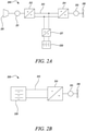
- the propulsion system of a hybrid electric aircraft is generally indicated at 200 and incorporates both an engine 210, such as the gas turbine engine 10 described above with reference to Figure 1 , and a battery 230. Both the engine 210 and the battery 230 are used as energy sources to power a motor-driven propeller 216, as well as ancillary electrical systems (not shown).
- the propulsion system 200 of the hybrid electric aircraft will typically further comprise a generator 211, an AC/DC converter 212, a high voltage DC (HVDC) distribution bus 213, a DC/AC converter 214, a motor 215 that drives the propeller 216, and a DC/DC converter 217.
- HVDC high voltage DC
- a shaft of the engine 210 is coupled to and drives the rotation of a shaft of the generator 211 which thereby produces alternating current.
- the AC/DC converter 212 which faces the generator 211, converts the alternating current into direct current which is fed to various electrical systems via the HVDC distribution bus 213. These electrical systems include the motor 215 that drives the propeller 216.
- the motor 215 will typically be a synchronous motor that interfaces with the HVDC distribution bus 213 via the DC/AC converter 214.
- the battery 230 which may be made up of a number of lithium ion battery modules connected in series and/or parallel, is connected to the HVDC distribution bus 213 via the DC/DC converter 217.
- the DC/DC converter 217 converts between a voltage of the battery 230 and a voltage of the HVDC distribution bus 213. In this way, the battery 230 can replace or supplement the power provided by the engine 210 (by discharging and thereby feeding the HVDC distribution bus 213) or can be charged using the power provided by the engine 210 (by being fed by the HVDC distribution bus 213).
- a battery will also appear in the propulsion system of a purely electric aircraft, generally indicated as 300 in Figure 2B .
- the battery 330 feeds a HVDC distribution bus 313, possibly via DC/DC converter (not shown), which delivers power to one or more synchronous motors 315 via a DC/AC converter 314.
- the one or more motors 315 drive the one or more propellers 316 that propel that aircraft.
- Batteries used in these applications may have high terminal voltages, for example 500V to 3kV.
- the use of high voltages advantageously allows for a reduction in the weight of the power distribution cabling, but it does create risk factors.
- a fault within one or more of the battery modules could lead to thermal runaway, creating a risk of fire and electric shock.
- cells may vent thermal products including flames, gas jets, projectiles and heat.
- a battery case may be used to help contain the risk of thermal events in the battery pack, but the case itself is not immune to damage.
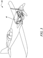
- Figure 3 shows a purely electric aircraft 100 that includes a high-voltage battery housed within a battery case 40. It can be seen that the battery case 40 is structurally connected to the airframe of the aircraft 100 such that mechanical loads will be transmitted through the battery case 40. Damage to a structural battery case 40, for example fire damage following thermal runaway in the battery, could have particularly severe consequences as it could damage the structural integrity of the airframe.
- a battery case is provided with a protective internal lining formed of ablative cork and a phenolic binder. It has been found that a lining of cork with a phenolic binder provides a battery case with surprisingly enhanced thermal and mechanical protection, without adding significant mass to the battery case.
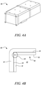
- FIGs 4A and 4B show a battery case 40 which, in use, houses a high-voltage battery 30, parts of which are visible in Figures 5 and 6B .
- the battery case 40 includes an enclosure or housing 41 that defines an internal cavity 42 for containing the battery 30.
- the enclosure 41 may be of any suitable construction given the application requirements, for example given the size and shape of the battery 30 to be used.
- the enclosure 41 may also formed of any suitable material or materials.
- the enclosure 41 comprises or is formed of a composite material, and this may particularly desirable where the battery case 40 is to be a structural component of a vehicle, for example an aircraft.
- an internal surface 43, 44 of the enclosure 41 facing the cavity 42 is provided with a protective lining 50.
- the protective lining 50 is formed of a cork material combined with a phenolic binder.
- the internal lining 50 protects the battery case 40 (for example the composite material of the case) against flame, gas jet, projectiles and heat rejected from batteries during any thermal runaway event that may occur during use, and also provides additional electrical insulation. It has been found that a lining comprising cork and phenolic binder is particularly effective in preventing the case 40 (for example the composite and associated resin system of the case 40) from exceeding its glass transition temperature (T g ), beyond which its mechanical properties would significantly change. This may be achieved through several mechanisms, for example:
- the combined cork and phenolic binder lining 50 may be formed in a number of different ways, including but not limited to mixing ground cork with a phenolic resin.
- the mixture may then be applied to the surface, for example by spraying the mixture through a nozzle.
- the mixture may be set it in the form of a sheet.
- the sheet of lining material can then be applied and bonded to the internal surface 43 using a suitable heat-resistant bonding agent.
- Suitable bonding agents include but are not limited to heat-resistant silicone and resin films.
- a phenolic resin film is used, and this may improve the heat and fire-resistance of the lining 50 and also reduce reactions between the lining 50 and bonding agent during curing.
- portions of the lining 50 may first be bonded to a carrier material (e.g., Kevlar (Registered Trade Mark) or another synthetic fibre) and the combined carrier and lining 50 bonded to the internal surface 43 of the enclosure 40.
- a carrier material e.g., Kevlar (Registered Trade Mark) or another synthetic fibre
- the thickness of the protective lining 50 may vary according to application requirements, with greater thicknesses providing additional protection against fire and thermal products but also additional mass.
- the thickness may typically be about 2-4mm, and in one specific example is about 3mm, though greater, lesser and non-uniform thicknesses could be used.
- the enclosure 41 includes a top internal surface 44 and a bottom internal surface 45 opposite the top internal surface 44.
- top surface and “bottom” surface are used with reference to the orientation of the battery case 40 when oriented as intended for normal use. Normal use may, for instance, be the level flight of an aircraft in which the battery case 40 is to be located.
- the bottom internal surface 45 is not lined with the thermally protective lining 50 or is lined with a thinner lining than the top internal surface 44. This may reduce the cost, mass and complexity of the battery case 50 without negatively affecting its performance, since flames vented by the cells of the battery pack will generally rise and not strike the bottom internal surface 45.
- the battery case 40 may also include one or more internal walls or barriers 46a, 46b that divide the cavity 42 into two or more regions 42a, 42b, 42c.
- the battery 30 comprises three independent battery channels and each one of the three regions 42a, 42b, 42c houses one of the battery channels.
- the internal walls 46a, 46b help electrically and thermally insulate the regions 42a, 42b, 42c from each other, and one or both sides of one or more of the internal walls 46a, 46b may conveniently be lined with the protective lining 50 of cork and phenolic binder.
- the thickness of the protective lining 50 on the internal walls 46a, 46b may be the same as or similar to the thickness of the protective lining on the internal surface of the enclosure 41.
- the protective lining 50 may include one or more joints 53, 54 where two adjacent portions 51, 52 of the lining 50 meet.
- the provision of joints 53, 54 may be necessary because of the geometry of enclosure 41, for example where the enclosure 41 has corners or curves which cannot be satisfactorily covered by a single, typically flat, portion of the lining 50.
- joints 53, 54 may be utilized due to size constraints, for example where a single sheet of protective lining 50 of a size sufficient to cover an entire section of the enclosure 40 is unavailable.
- a joint 54 is provided at the interface between two portions 51, 52 of the lining which cover a substantially planar section of the internal surface enclosure 41.
- Joints 53, 54 between adjacent lining portions 51, 52 may be formed in a variety of different ways, and may be adapted to reduce the extent to which the joints are points of thermal and mechanical weakness. Examples include, but are not limited to:
- a lining 50 of cork and a phenolic binder has a relatively large minimum bend radius.
- the minimum bend radius may be somewhat reduced by first bonding a substantially flat portion of the lining material 50 to a carrier material, for example a relatively strong and flexible carrier material such as Kevlar (Registered Trade Mark).
- the lining material 50 may be subject to a combined heat and compression cycle, for example around a jig, prior to its application so that the lining 50 can more flexibly applied to the internal surface 41 of the enclosure 40.
- FIG. 6B shows part of a high-voltage battery 30 such as may be used in an electric aircraft or hybrid electric aircraft.
- the battery 30 includes a large number of series and parallel connected lithium-ion battery cells, in particular 4.2V 18650 cylindrical cells, held within a carrier frame.
- cells may vent thermal products including flames, gas jets, projectiles and heat. This release is typically directional. For instance, cylindrical cells will typically vent in a direction parallel to the axis of the cylinder and from one on the flat ends of the cylinder.
- the battery 30 may be designed and constructed so as to reduce the impact of the release of the thermal products.
- the cell venting directions may be oriented away from the core of the battery. In other words, the cells should vent outward away from the battery. This will discourage the spread of thermal events through the battery and instead direct the thermal products towards the internal lining 50 which is adapted to protect the battery case 40.
- the battery case 40 may be designed such that any joints 53, 54 in the internal lining are located so as not to coincide with any of the cell venting directions.
- the joints 53, 54 may be relatively thermally and mechanically weak compared to the rest of the lining 50.
- the precise locations to be avoided will depend on the type of cells used and the design of the battery 30, but can be readily defined for a given battery 30.
- FIG. 7A this illustrates a method of fabricating a battery case 40 with a protective lining in accordance with the present disclosure.
- a battery case assembly which, when assembled, includes an enclosure 41 having a cavity 42 for housing a battery is obtained.
- the assembly can, for example, include one or more integrally formed walls such as those shown in Figure 6 which, when assembled together, form a complete battery case 40 such as the one shown in Figure 4A .
- the assembly and its parts can be of any suitable construction and of any suitable material, as discussed above.
- a thermally protective lining 50 comprising cork and a phenolic binder is applied to a surface of the battery case assembly.
- the surface to which the lining 50 is applied is a surface which, when the assembly is assembled, is an internal surface 43 of the enclosure 41 that faces the cavity 42.
- the protective lining 50 may be pre-prepared and then applied to the surface using a bonding agent, as discussed above. In some cases the protective lining may be cut or machined to shape prior to its application, or may be sprayed onto the surface.
- Portions of lining 50 may be applied to multiple surfaces of the battery case assembly, for example to all internal surfaces of the enclosure 41. Where adjacent portions of lining meet, joints 53, 54 may be provided as described above with reference to Figures 4B and 6A . The joints 53, 54 may be provided only at locations that do not coincide with one or more predetermined flame directions of the battery 30 that is to be housed within the enclosure 41.
- the parts of the battery case assembly may be assembled together to form the battery case 40.
- the case 40 or its parts may be subject to one or more additional processing steps such as curing.
- Figure 7B is a flow chart illustrating how a portion of the lining 50 may be applied to a curved surface of the battery case assembly.
- the protective lining comprises cork and a phenolic binder, as discussed above. It may, for example, be a relatively thin sheet of the material formed by setting a mixture of cork granules and phenolic resin.
- the generally flat piece of protective lining is bonded to a carrier material.
- the carrier material may be a relatively flexible, strong and lightweight material, for example Kevlar (Registered Trade Mark) or another synthetic fibre material. It may be bonded in any suitable way, for example using a phenolic resin or another bonding agent.
- the use of a carrier material may increase the strength of the lining, decreasing the bend radius below which the lining may fracture.
- the generally flat piece of protective lining is bent into a curved piece of lining that will conform to a predefined curved shape of a surface of the battery case assembly. Bending the generally flat piece of protective lining may, for example, include placing the lining over a jig and subjecting the lining to cycles of combined heat and compression until a desired degree of bend or curvature is achieved.
- the curved piece of protective lining is applied to a correspondingly curved surface of the battery case assembly.
- the lining may be applied using a bonding agent.
- the carrier may be removed prior to applying the lining to the surface or may be retained as part of the lining.
Landscapes
- Chemical & Material Sciences (AREA)
- Chemical Kinetics & Catalysis (AREA)
- Electrochemistry (AREA)
- General Chemical & Material Sciences (AREA)
- Engineering & Computer Science (AREA)
- Manufacturing & Machinery (AREA)
- Aviation & Aerospace Engineering (AREA)
- Composite Materials (AREA)
- Inorganic Chemistry (AREA)
- Materials Engineering (AREA)
- Battery Mounting, Suspending (AREA)
Abstract
Description
- The present disclosure relates to a battery case having a protective lining, particularly but not exclusively for an aircraft.
- Future aerospace applications such as more electric, hybrid electric and purely electric aircraft will likely use high voltage battery packs made up of a number of series- and/or parallel- connected battery modules. These battery packs may, for example, be used to power one or more motors used to propel the aircraft and/or to provide power to one or more ancillary systems.
- Heating of battery cells beyond their normal operating range can occur for various reasons. For example, a fault may develop in one or more of the modules, or the modules could be exposed to an external source of heat such as a fire, direct sunshine or exhaust gas from a gas turbine engine. Heat from one battery module can spread to others, which could lead to thermal runaway of an entire battery pack. Excessive heating and thermal runaway creates a risk of fire and with it damage to the battery, damage to the surrounding structure of the aircraft and risk of electric shock, for example by causing damage to electrical insulation and structures that support the cells and bus bars.
- Clearly it is desirable to protect against the consequences of excessive cell heating. To this end, practical systems, particularly those in the automotive sector, typically use a combination of protective measures. This usually includes a Battery Management System (BMS) which monitors the temperatures of the battery cells and, for example, controls a breaker to isolate modules that are overheating. Other measures include the use of protective materials in the vehicle, for example thermal and flame barrier materials such as stainless steel and titanium; intumescent materials made from mineral fibres; and insulating materials such as Alumino Silicate Wool (ASW).
- The present disclosure provides a battery case with a protective lining that may find particular application in aircraft, particularly but not exclusively more electric, purely electric or hybrid electric aircraft.
- According to a first aspect there is provided a battery case for housing a battery. The battery case comprises an enclosure having a cavity for housing the battery. An internal surface of the enclosure facing the cavity includes a protective lining comprising cork and a phenolic binder.
- It will be understood that the battery may be any suitable collection of battery cells, for example a battery pack; one or more channels of a multi-channel battery pack; one or more modules of a multi-module battery pack; or any other sub-unit of a battery pack, channel or module.
- It will be understood that a phenolic binder is a phenolic resin (also called a phenol formaldehyde resin) used to bind or hold material, in this case cork which may be in a granular form, together.
- The protective lining may cover substantially all or only part of the internal surface of the enclosure. The protective lining may be the sole or one of a plurality of layers on the internal surface of the enclosure.
- The battery case may comprise one or more internal walls so that the cavity has a plurality of regions separated by the internal walls. One or a plurality of surfaces of at least one of the internal walls may include a protective lining comprising cork and a phenolic binder.
- At least a portion of the protective lining may be bonded to a carrier material. The portion of the lining that is bonded the carrier material may be bent or curved to conform to a shape of the, or part of the, enclosure.
- The protective lining may include at least a first lining portion covering a first section of the internal surface and comprising cork and a phenolic binder; a second lining portion covering a second section of the internal surface and comprising cork and a phenolic binder; and a joint at an interface between the first and second lining portions.
- The joint may comprise a phenolic cork putty and/or a plurality of overlapping layers of the protective lining.
- The enclosure may comprise a composite material having a cork core.
- The enclosure may have a top internal surface and a bottom internal surface opposite the top internal surface. The bottom internal surface may not be lined with the protective lining or may be lined with a thinner lining than the top internal surface.
- According to a second aspect, there is provided a battery assembly, comprising: a battery case according to the first aspect; and a battery within the cavity of the battery case.
- The battery may define one or more flame or vent directions in which battery cells of the battery vent flames or other thermal products. The protective lining of the battery case may include at least one joint, each joint joining two or more adjacent lining portions of the protective lining. Each of the at least one joints may be located so as not to coincide with any of the one more flame directions of the battery pack. For cylindrical cells, the flame directions may be parallel to the longitudinal axes of the cylinders.
- According to a third aspect, there is provided an aircraft comprising the battery assembly of the second aspect. The aircraft may be configured so that the battery case is a structural component of the aircraft.
- According to a fourth aspect, there is provided a method of fabricating a battery assembly. The method comprises: obtaining a battery case assembly which, when assembled, includes an enclosure having a cavity for housing a battery; and applying a protective lining comprising cork and a phenolic binder to a surface of the battery case assembly. When the battery case assembly is assembled, the surface is an internal surface of the enclosure.
- Applying the protective lining to the surface may comprise: obtaining a generally flat piece of protective lining comprising cork and a phenolic binder; bending the generally flat piece of the protective lining into a curved piece of protective lining; and applying the curved piece of protective lining to the surface of the battery case assembly.
- Prior to bending the generally flat piece of the protective lining, a carrier material may be bonded to the generally flat piece of the protective lining.
- Bending the generally flat piece of the protective lining into a curved piece of protective lining may comprise applying one or more cycles of heating and compression to the generally flat piece of the protective lining.
- Applying the protective lining to the surface may comprise spraying a cork and phenolic binder mixture onto the surface.
- Applying the protective lining to the surface may comprise machining a piece of lining material to conform to a shape of the surface and applying the machined piece to the surface.
- The skilled person will appreciate that except where mutually exclusive, a feature described in relation to any one of the above aspects may be applied mutatis mutandis to any other aspect. Furthermore except where mutually exclusive any feature described herein may be applied to any aspect and/or combined with any other feature described herein.
- Embodiments will now be described by way of example only, with reference to the Figures, in which:
-
Figure 1 is a sectional side view of a gas turbine engine; -
Figure 2A is a schematic illustration of a hybrid electric aircraft propulsion system; -
Figure 2B is a schematic illustration of a purely electric aircraft propulsion system; -
Figure 3 is a perspective view of an aircraft incorporating a battery case as a structural component. -
Figure 4A is a perspective view of a battery case; -
Figure 4B is a cross-sectional view of a portion of a battery case with a protective lining; -
Figure 5 is a perspective view of a battery case illustrating internal walls; -
Figure 6A is a cross-sectional view illustrating a joint in a protective lining; -
Figure 6B is a perspective view of a battery; -
Figure 7A is a flow chart illustrating a method of fabricating a battery case; and -
Figure 7B is a flow chart illustrating further optional details of the method ofFigure 7A . - With reference to
Figure 1 , a gas turbine engine is generally indicated at 10, having a principal androtational axis 11. Theengine 10 comprises, in axial flow series, anair intake 12, apropulsive fan 13, anintermediate pressure compressor 14, a high-pressure compressor 15,combustion equipment 16, a high-pressure turbine 17, anintermediate pressure turbine 18, a low-pressure turbine 19 and anexhaust nozzle 20. Anacelle 21 generally surrounds theengine 10 and defines both theintake 12 and theexhaust nozzle 20. - The
gas turbine engine 10 works in the conventional manner so that air entering theintake 12 is accelerated by thefan 13 to produce two air flows: a first air flow into theintermediate pressure compressor 14 and a second air flow which passes through a bypass duct 22 to provide propulsive thrust. Theintermediate pressure compressor 14 compresses the air flow directed into it before delivering that air to thehigh pressure compressor 15 where further compression takes place. - The compressed air exhausted from the high-
pressure compressor 15 is directed into thecombustion equipment 16 where it is mixed with fuel and the mixture combusted. The resultant hot combustion products then expand through, and thereby drive the high, intermediate and low-pressure turbines nozzle 20 to provide additional propulsive thrust. The high 17, intermediate 18 and low 19 pressure turbines drive respectively thehigh pressure compressor 15,intermediate pressure compressor 14 andfan 13, each by suitable interconnecting shaft. - Other gas turbine engines to which the present disclosure may be applied may have alternative configurations. By way of example such engines may have an alternative number of interconnecting shafts (e.g. two) and/or an alternative number of compressors and/or turbines. Further the engine may comprise a gearbox provided in the drive train from a turbine to a compressor and/or fan. The gas turbine engine may also incorporate or interface with one or more batteries, for example to power ancillary electrical systems and/or to cooperate with one or more electric machines involved in the transfer of mechanical power to and from one or more of the interconnecting shafts.
- Now referring to
Figure 2A , the propulsion system of a hybrid electric aircraft is generally indicated at 200 and incorporates both anengine 210, such as thegas turbine engine 10 described above with reference toFigure 1 , and abattery 230. Both theengine 210 and thebattery 230 are used as energy sources to power a motor-drivenpropeller 216, as well as ancillary electrical systems (not shown). Thepropulsion system 200 of the hybrid electric aircraft will typically further comprise agenerator 211, an AC/DC converter 212, a high voltage DC (HVDC)distribution bus 213, a DC/AC converter 214, amotor 215 that drives thepropeller 216, and a DC/DC converter 217. - A shaft of the
engine 210 is coupled to and drives the rotation of a shaft of thegenerator 211 which thereby produces alternating current. The AC/DC converter 212, which faces thegenerator 211, converts the alternating current into direct current which is fed to various electrical systems via theHVDC distribution bus 213. These electrical systems include themotor 215 that drives thepropeller 216. Themotor 215 will typically be a synchronous motor that interfaces with theHVDC distribution bus 213 via the DC/AC converter 214. - The
battery 230, which may be made up of a number of lithium ion battery modules connected in series and/or parallel, is connected to theHVDC distribution bus 213 via the DC/DC converter 217. The DC/DC converter 217 converts between a voltage of thebattery 230 and a voltage of theHVDC distribution bus 213. In this way, thebattery 230 can replace or supplement the power provided by the engine 210 (by discharging and thereby feeding the HVDC distribution bus 213) or can be charged using the power provided by the engine 210 (by being fed by the HVDC distribution bus 213). - A battery will also appear in the propulsion system of a purely electric aircraft, generally indicated as 300 in
Figure 2B . Thebattery 330 feeds aHVDC distribution bus 313, possibly via DC/DC converter (not shown), which delivers power to one or moresynchronous motors 315 via a DC/AC converter 314. The one ormore motors 315 drive the one ormore propellers 316 that propel that aircraft. - Batteries used in these applications may have high terminal voltages, for example 500V to 3kV. The use of high voltages advantageously allows for a reduction in the weight of the power distribution cabling, but it does create risk factors. For example, a fault within one or more of the battery modules could lead to thermal runaway, creating a risk of fire and electric shock. Further, during a thermal event, cells may vent thermal products including flames, gas jets, projectiles and heat. A battery case may be used to help contain the risk of thermal events in the battery pack, but the case itself is not immune to damage.
- These risks may be particularly acute where the battery case is a structural member of the airframe. By way of an example,
Figure 3 shows a purelyelectric aircraft 100 that includes a high-voltage battery housed within abattery case 40. It can be seen that thebattery case 40 is structurally connected to the airframe of theaircraft 100 such that mechanical loads will be transmitted through thebattery case 40. Damage to astructural battery case 40, for example fire damage following thermal runaway in the battery, could have particularly severe consequences as it could damage the structural integrity of the airframe. - In accordance with the present disclosure, a battery case is provided with a protective internal lining formed of ablative cork and a phenolic binder. It has been found that a lining of cork with a phenolic binder provides a battery case with surprisingly enhanced thermal and mechanical protection, without adding significant mass to the battery case.
-
Figures 4A and 4B show abattery case 40 which, in use, houses a high-voltage battery 30, parts of which are visible inFigures 5 and6B . - The
battery case 40 includes an enclosure orhousing 41 that defines aninternal cavity 42 for containing thebattery 30. Theenclosure 41 may be of any suitable construction given the application requirements, for example given the size and shape of thebattery 30 to be used. Theenclosure 41 may also formed of any suitable material or materials. In some examples, theenclosure 41 comprises or is formed of a composite material, and this may particularly desirable where thebattery case 40 is to be a structural component of a vehicle, for example an aircraft. - As can be seen in
Figure 4B , aninternal surface enclosure 41 facing thecavity 42 is provided with aprotective lining 50. Theprotective lining 50 is formed of a cork material combined with a phenolic binder. - The
internal lining 50 protects the battery case 40 (for example the composite material of the case) against flame, gas jet, projectiles and heat rejected from batteries during any thermal runaway event that may occur during use, and also provides additional electrical insulation. It has been found that a lining comprising cork and phenolic binder is particularly effective in preventing the case 40 (for example the composite and associated resin system of the case 40) from exceeding its glass transition temperature (Tg), beyond which its mechanical properties would significantly change. This may be achieved through several mechanisms, for example: - As an ablative material, with the cork material protecting the
case 40 through loss of mass. This mechanical removal and pyrolysis of gas takes energy from the system, while also possibly exposing fresh, cooler material behind. - The cork material may provide a low density insulator through its natural microstructure, which may be made up of pentagonal or hexagonal prisms containing an air-like gas.
- When exposed to a flame source, the lining material chars, forming a stronger surface layer, which also acts to seal the surface and help to snub out fire, reducing the risk of the material igniting.
- The combined cork and phenolic binder lining 50 may be formed in a number of different ways, including but not limited to mixing ground cork with a phenolic resin. The mixture may then be applied to the surface, for example by spraying the mixture through a nozzle. In another example, the mixture may be set it in the form of a sheet. The sheet of lining material can then be applied and bonded to the
internal surface 43 using a suitable heat-resistant bonding agent. - Suitable bonding agents include but are not limited to heat-resistant silicone and resin films. In one particular example a phenolic resin film is used, and this may improve the heat and fire-resistance of the
lining 50 and also reduce reactions between the lining 50 and bonding agent during curing. In some examples, described in more detail below, portions of the lining 50 may first be bonded to a carrier material (e.g., Kevlar (Registered Trade Mark) or another synthetic fibre) and the combined carrier and lining 50 bonded to theinternal surface 43 of theenclosure 40. - The thickness of the
protective lining 50 may vary according to application requirements, with greater thicknesses providing additional protection against fire and thermal products but also additional mass. The thickness may typically be about 2-4mm, and in one specific example is about 3mm, though greater, lesser and non-uniform thicknesses could be used. - Now referring to
Figure 4B andFigure 5 , theenclosure 41 includes a topinternal surface 44 and a bottominternal surface 45 opposite the topinternal surface 44. It will be understood that the designations "top" surface and "bottom" surface are used with reference to the orientation of thebattery case 40 when oriented as intended for normal use. Normal use may, for instance, be the level flight of an aircraft in which thebattery case 40 is to be located. In some examples, the bottominternal surface 45 is not lined with the thermallyprotective lining 50 or is lined with a thinner lining than the topinternal surface 44. This may reduce the cost, mass and complexity of thebattery case 50 without negatively affecting its performance, since flames vented by the cells of the battery pack will generally rise and not strike the bottominternal surface 45. - Referring to
Figure 5 , thebattery case 40 may also include one or more internal walls orbarriers cavity 42 into two ormore regions battery 30 comprises three independent battery channels and each one of the threeregions internal walls regions internal walls protective lining 50 of cork and phenolic binder. The thickness of theprotective lining 50 on theinternal walls enclosure 41. - Now referring to
Figure 4B andFigure 6A , it can be seen that theprotective lining 50 may include one ormore joints adjacent portions joints enclosure 41, for example where theenclosure 41 has corners or curves which cannot be satisfactorily covered by a single, typically flat, portion of thelining 50. This is illustrated inFigure 4B where a joint 53 is present in a corner of theenclosure 41. In other examples, joints 53, 54 may be utilized due to size constraints, for example where a single sheet ofprotective lining 50 of a size sufficient to cover an entire section of theenclosure 40 is unavailable. This is illustrated inFigure 6A , where a joint 54 is provided at the interface between twoportions internal surface enclosure 41. -
Joints adjacent lining portions -
Adjacent portions protective lining 50 may be positioned close together and the joint 53, 54 filled with a heat-resistant material. Examples of heat-resistant materials include high temperatures silicone, resins such as FST (Fire, Smoke and Toxicity) rated resins and phenolic resins, and/or phenolic cork putty. A phenolic cork putty may be formed by mixing ground cork with a phenolic resin to form a paste, which can be used to seal the joint 53, 54 prior to curing. - A joint 53, 54 may comprise multiple overlapping layers of the
protective lining 50. InFigure 6A , this is achieved by shaping (e.g., tapering) and/or bending the terminating ends of theadjacent portions region 54 having two overlappinglayers 54i, 54ii. Any space between the overlappinglayers 54i, 54ii may be filled with a sealing material, for example a heat-resistant resin or phenolic cork putty. - Multiple layers may be provided in other ways, for example bonding or taping one or more separate, additional sections of lining
material 50 over the joint region. - Filling and/or bonding material used to fill the joint 53, 54 may be applied so as to stop short of an exposed edge of the joint. This is illustrated in
Figure 6A , where aregion 541 of the joint 54 adjacent an exposededge 542 is left free of filling material so as to reduce the risk its exposure to the heat and flame. - Exposed edges of a joint, such as the
edge 542 inFigure 6A , may be treated with an additional flame retardant coating. - While one or
more joints internal surface 43 of theenclosure 41, the need for joints may be reduced by bending or otherwise curving sections ofprotective lining 50 such that the lining 50 can conform to a non-planar region of theenclosure 40. Generally speaking, a lining 50 of cork and a phenolic binder has a relatively large minimum bend radius. However the minimum bend radius may be somewhat reduced by first bonding a substantially flat portion of thelining material 50 to a carrier material, for example a relatively strong and flexible carrier material such as Kevlar (Registered Trade Mark). Additionally or alternatively, the liningmaterial 50 may be subject to a combined heat and compression cycle, for example around a jig, prior to its application so that the lining 50 can more flexibly applied to theinternal surface 41 of theenclosure 40. -
Figure 6B shows part of a high-voltage battery 30 such as may be used in an electric aircraft or hybrid electric aircraft. In this example thebattery 30 includes a large number of series and parallel connected lithium-ion battery cells, in particular 4.2V 18650 cylindrical cells, held within a carrier frame. - During a thermal event, cells may vent thermal products including flames, gas jets, projectiles and heat. This release is typically directional. For instance, cylindrical cells will typically vent in a direction parallel to the axis of the cylinder and from one on the flat ends of the cylinder.
- The
battery 30 may be designed and constructed so as to reduce the impact of the release of the thermal products. For instance, as can be seen inFigure 6B , the cell venting directions may be oriented away from the core of the battery. In other words, the cells should vent outward away from the battery. This will discourage the spread of thermal events through the battery and instead direct the thermal products towards theinternal lining 50 which is adapted to protect thebattery case 40. - Furthermore, the
battery case 40 may be designed such that anyjoints joints lining 50. Thus, by locating all of thejoints lining 50 and thus thebattery case 40 are reduced. The precise locations to be avoided will depend on the type of cells used and the design of thebattery 30, but can be readily defined for a givenbattery 30. - Now turning to
Figure 7A , this illustrates a method of fabricating abattery case 40 with a protective lining in accordance with the present disclosure. - At 61, a battery case assembly which, when assembled, includes an
enclosure 41 having acavity 42 for housing a battery is obtained. The assembly can, for example, include one or more integrally formed walls such as those shown inFigure 6 which, when assembled together, form acomplete battery case 40 such as the one shown inFigure 4A . The assembly and its parts can be of any suitable construction and of any suitable material, as discussed above. - At 62, a thermally
protective lining 50 comprising cork and a phenolic binder is applied to a surface of the battery case assembly. The surface to which thelining 50 is applied is a surface which, when the assembly is assembled, is aninternal surface 43 of theenclosure 41 that faces thecavity 42. Theprotective lining 50 may be pre-prepared and then applied to the surface using a bonding agent, as discussed above. In some cases the protective lining may be cut or machined to shape prior to its application, or may be sprayed onto the surface. - Portions of lining 50 may be applied to multiple surfaces of the battery case assembly, for example to all internal surfaces of the
enclosure 41. Where adjacent portions of lining meet,joints Figures 4B and6A . Thejoints battery 30 that is to be housed within theenclosure 41. - After applying the lining 50 to all of the desired surfaces of the assembly, the parts of the battery case assembly may be assembled together to form the
battery case 40. Optionally, prior to or after assembly of the case, thecase 40 or its parts may be subject to one or more additional processing steps such as curing. -
Figure 7B is a flow chart illustrating how a portion of the lining 50 may be applied to a curved surface of the battery case assembly. - At 621, a generally flat piece of protective lining is obtained. The protective lining comprises cork and a phenolic binder, as discussed above. It may, for example, be a relatively thin sheet of the material formed by setting a mixture of cork granules and phenolic resin.
- Optionally, at 622, the generally flat piece of protective lining is bonded to a carrier material. The carrier material may be a relatively flexible, strong and lightweight material, for example Kevlar (Registered Trade Mark) or another synthetic fibre material. It may be bonded in any suitable way, for example using a phenolic resin or another bonding agent. The use of a carrier material may increase the strength of the lining, decreasing the bend radius below which the lining may fracture.
- At 623, the generally flat piece of protective lining is bent into a curved piece of lining that will conform to a predefined curved shape of a surface of the battery case assembly. Bending the generally flat piece of protective lining may, for example, include placing the lining over a jig and subjecting the lining to cycles of combined heat and compression until a desired degree of bend or curvature is achieved.
- At 624, the curved piece of protective lining is applied to a correspondingly curved surface of the battery case assembly. As discussed above, the lining may be applied using a bonding agent. Where the protective lining was bonded to a carrier material, the carrier may be removed prior to applying the lining to the surface or may be retained as part of the lining.
- Various modifications may be made to the
battery case 40 and methods described above. For example: - An external surface of the
enclosure 41 may also be provided with a protective lining of cork and phenolic binder. - Another aircraft component may be provided with a protective lining of cork and phenolic binder to protect the component against battery fire.
- The
enclosure 41 may be made of a composite material having a cork core. - One or more additional layers, in addition to the cork and phenolic binder layer, may be provided on the
internal surface 43 of theenclosure 41. - Rather than applying a sheet of the protective material, suitably sized and shaped pieces may be machined and applied. This may allow for the coverage of more complex geometries.
- Rather than applying a sheet or machined piece of protective lining, a mixture of cork and binder may be applied to a surface of the battery case by spraying. As the viscosity of the mixture will typically be quite high, the use of a relatively large spray nozzle (of the order of ten to hundreds of millimetres in diameter) and a propellant may be preferable. The viscosity of the mixture can be varied by changing the ratio of the cork granules and resin, and/or by changing the size of the cork granules.
- Alternative, non-phenolic, binders may be used. Entirely different, non-cork based, protective linings may be used in combination with the principles described herein, for example the use of joints that do not coincide with cell venting directions.
- It will be understood that the invention is not limited to the embodiments above-described and various modifications and improvements can be made without departing from the concepts described herein. Except where mutually exclusive, any of the features may be employed separately or in combination with any other features and the disclosure extends to and includes all combinations and subcombinations of one or more features described herein.
Claims (15)
- A battery case (40) for housing a battery assembly (30), comprising:
an enclosure (41) having a cavity (42) for housing the battery assembly, wherein an internal surface (43) of the enclosure facing the cavity includes a protective lining (50) comprising cork and a phenolic binder. - The battery case (40) of claim 1, comprising one or more internal walls (46a, 46b) so that the cavity (42) has a plurality of regions (42a, 42b, 42c) separated by the internal walls, at least one of the internal walls including a protective lining (50) comprising cork and a phenolic binder.
- The battery case (40) of claim 1 or claim 2, wherein at least a portion of the protective lining (50) is bonded to a carrier material.
- The battery case (40) of claim 3, wherein the portion of the lining (50) that is bonded the carrier material is bent or curved to conform to a shape of at least a portion of the enclosure (41).
- The battery case (40) of any one of the preceding claims, wherein the protective lining (50) includes at least a first lining portion (51) covering a first section of the internal surface (41) and comprising cork and a phenolic binder; a second lining portion (52) covering a second section of the internal surface and comprising cork and a phenolic binder; and a joint (53, 54) at an interface between the first and second lining portions.
- The battery case (40) of claim 5, wherein the joint (53, 54) comprises a phenolic cork putty.
- The battery case (40) of claim 5 or 6, wherein the joint (54) comprises a plurality of overlapping layers (54i, 54ii) of the protective lining (50).
- The battery case (40) of any one of the preceding claims, wherein the enclosure (41) comprises a composite material having a cork core.
- The battery case (40) of any one of the preceding claims, wherein the enclosure (41) has a top internal surface (44) and a bottom internal surface (45) opposite the top internal surface, and wherein the bottom internal surface is not lined with the thermally protective lining (50) or is lined with a thinner lining than the top internal surface.
- The battery case (40) of any one of the preceding claims, wherein an external surface of the enclosure (41) is also lined with a thermally protective lining (50) comprising cork and a phenolic binder
- A battery assembly, comprising:a battery case (40) as claimed in any one of claims 1 to 10; anda battery (30) within the cavity (42) of the battery case.
- The assembly of claim 11, wherein:the battery (30) defines one or more flame directions in which battery cells of the battery vent flames;the protective lining (50) of the battery case (40) includes at least one joint (53, 54), each joint provided at an interface between two or more adjacent lining portions (51, 52) of the protective lining; andeach of the at least one joints is located so as not to coincide with any of the one or more flame directions of the battery pack.
- An aircraft (100) comprising a battery assembly as claimed in claim 11 or claim 12.
- The aircraft (100) of claim 13, configured so that the battery case (40) is a structural component of the aircraft.
- A method of fabricating a battery case (40) having a protective lining, the method comprising:obtaining (61) a battery case assembly which, when assembled, includes an enclosure (40) having a cavity (42) for housing a battery (30); andapplying (62) a protective lining (50) comprising cork and a phenolic binder to a surface of the battery case assembly,wherein, when the battery case assembly is assembled, the surface is an internal surface (41) of the enclosure.
Applications Claiming Priority (1)
| Application Number | Priority Date | Filing Date | Title |
|---|---|---|---|
| GB2010945.0A GB2597652B (en) | 2020-07-16 | 2020-07-16 | Battery case |
Publications (1)
| Publication Number | Publication Date |
|---|---|
| EP3940839A1 true EP3940839A1 (en) | 2022-01-19 |
Family
ID=72338919
Family Applications (1)
| Application Number | Title | Priority Date | Filing Date |
|---|---|---|---|
| EP21182648.2A Withdrawn EP3940839A1 (en) | 2020-07-16 | 2021-06-30 | Battery case |
Country Status (4)
| Country | Link |
|---|---|
| US (1) | US12586852B2 (en) |
| EP (1) | EP3940839A1 (en) |
| CN (1) | CN113948809A (en) |
| GB (1) | GB2597652B (en) |
Citations (4)
| Publication number | Priority date | Publication date | Assignee | Title |
|---|---|---|---|---|
| US4204899A (en) * | 1978-09-12 | 1980-05-27 | The United States Of America As Represented By The Administrator Of The National Aeronautics And Space Administration | Cork-resin ablative insulation for complex surfaces and method for applying the same |
| WO2010119431A2 (en) * | 2009-04-16 | 2010-10-21 | Unilin, Bvba | Board material, methods for manufacturing board material and panel which contains such board material. |
| US20150221914A1 (en) * | 2014-02-03 | 2015-08-06 | Pyrophobic Systems, Ltd. | Intumescent Battery Housing |
| US20190348725A1 (en) * | 2016-11-29 | 2019-11-14 | Samsung Sdi Co., Ltd. | Wall structure of battery cell, battery sub-module, battery module, or a battery system |
Family Cites Families (9)
| Publication number | Priority date | Publication date | Assignee | Title |
|---|---|---|---|---|
| US2121791A (en) * | 1934-09-14 | 1938-06-28 | Crown Cork & Seal Co | Cork composition and method of making |
| US5829669A (en) * | 1997-02-06 | 1998-11-03 | Sonoco Products Company | Tubular container and methods and apparatus for manufacturing same |
| KR100601534B1 (en) | 2004-07-28 | 2006-07-19 | 삼성에스디아이 주식회사 | Battery exterior material and lithium polymer battery using same |
| US8261931B2 (en) * | 2008-10-28 | 2012-09-11 | Caterpillar Inc. | Fluid tank having a heat-activated adhesive joint |
| DE102010048365B4 (en) * | 2010-10-13 | 2012-08-23 | Airbus Operations Gmbh | Fabric and aircraft fuselage with such a sheet |
| US8425196B2 (en) * | 2011-01-28 | 2013-04-23 | General Electric Company | Wind turbine blades with a hardened substrate construction |
| KR101655564B1 (en) | 2014-11-06 | 2016-09-07 | 주식회사 엘지화학 | Pouch case for secondary battery and pouch-type secondary battery comprising the same |
| DE102014018752A1 (en) * | 2014-12-16 | 2016-06-16 | Daimler Ag | Battery device with cork insulation |
| US10933971B2 (en) * | 2017-12-08 | 2021-03-02 | Wing Aviation Llc | Injection molded wing structure for aerial vehicles |
-
2020
- 2020-07-16 GB GB2010945.0A patent/GB2597652B/en active Active
-
2021
- 2021-06-16 CN CN202110666808.3A patent/CN113948809A/en active Pending
- 2021-06-30 EP EP21182648.2A patent/EP3940839A1/en not_active Withdrawn
- 2021-07-12 US US17/305,634 patent/US12586852B2/en active Active
Patent Citations (4)
| Publication number | Priority date | Publication date | Assignee | Title |
|---|---|---|---|---|
| US4204899A (en) * | 1978-09-12 | 1980-05-27 | The United States Of America As Represented By The Administrator Of The National Aeronautics And Space Administration | Cork-resin ablative insulation for complex surfaces and method for applying the same |
| WO2010119431A2 (en) * | 2009-04-16 | 2010-10-21 | Unilin, Bvba | Board material, methods for manufacturing board material and panel which contains such board material. |
| US20150221914A1 (en) * | 2014-02-03 | 2015-08-06 | Pyrophobic Systems, Ltd. | Intumescent Battery Housing |
| US20190348725A1 (en) * | 2016-11-29 | 2019-11-14 | Samsung Sdi Co., Ltd. | Wall structure of battery cell, battery sub-module, battery module, or a battery system |
Also Published As
| Publication number | Publication date |
|---|---|
| US12586852B2 (en) | 2026-03-24 |
| CN113948809A (en) | 2022-01-18 |
| GB2597652A (en) | 2022-02-09 |
| GB202010945D0 (en) | 2020-09-02 |
| GB2597652B (en) | 2023-02-08 |
| US20220021059A1 (en) | 2022-01-20 |
Similar Documents
| Publication | Publication Date | Title |
|---|---|---|
| EP3823080B1 (en) | Battery module | |
| EP3293366B1 (en) | Reinforced fan containment case for a gas turbine engine | |
| CN112839868B (en) | Aircraft wing spar with integrated power unit and associated systems and methods | |
| EP2946925B1 (en) | Fire resistant electrical panel | |
| JP5865999B2 (en) | Stacked noodles for high-performance pull-off against composite stringers | |
| EP0107727B1 (en) | Heat insulating blanket | |
| EP2959521B1 (en) | Aircraft including mitigation system for rechargeable batteries | |
| US20150175272A1 (en) | Reinforced primary structure for an attachment pylon | |
| CN103183128A (en) | Internal shield, aircraft with the internal shield, and correlation methods | |
| CN115799738A (en) | Hybrid composite system for battery casings with improved thermal performance | |
| US20050226714A1 (en) | Method and apparatus for fabricating gas turbine engines | |
| EP4510312A1 (en) | Battery and electrical device | |
| EP2874810A1 (en) | Fire guards and materials therefor | |
| US20160211495A1 (en) | Fire guards and materials therefor | |
| US12586852B2 (en) | Battery case | |
| EP3187695A1 (en) | A wrap comprising sheets of graphene for a casing of a rotating member, corresponding turbofan engine and method of asssaembling a turbofan engine | |
| GB2620459A (en) | Enclosure | |
| GB2519067A (en) | Fire guards and materials therefor | |
| GB2625255A (en) | Electric vehicle battery pack | |
| US20260005359A1 (en) | Enclosure | |
| US20250083790A1 (en) | System for the thermal management of an external electric-power-generating nacelle equipping an electrically powered airship, nacelle and airship equipped with said system | |
| US20250229906A1 (en) | Laminate Structure with Integrated Power Distribution | |
| EP4553960A1 (en) | Battery pack module | |
| GB2632824A (en) | A battery pack | |
| US20250349961A1 (en) | Integrated battery in composite panels |
Legal Events
| Date | Code | Title | Description |
|---|---|---|---|
| PUAI | Public reference made under article 153(3) epc to a published international application that has entered the european phase |
Free format text: ORIGINAL CODE: 0009012 |
|
| STAA | Information on the status of an ep patent application or granted ep patent |
Free format text: STATUS: THE APPLICATION HAS BEEN PUBLISHED |
|
| AK | Designated contracting states |
Kind code of ref document: A1 Designated state(s): AL AT BE BG CH CY CZ DE DK EE ES FI FR GB GR HR HU IE IS IT LI LT LU LV MC MK MT NL NO PL PT RO RS SE SI SK SM TR |
|
| STAA | Information on the status of an ep patent application or granted ep patent |
Free format text: STATUS: REQUEST FOR EXAMINATION WAS MADE |
|
| 17P | Request for examination filed |
Effective date: 20220616 |
|
| RBV | Designated contracting states (corrected) |
Designated state(s): AL AT BE BG CH CY CZ DE DK EE ES FI FR GB GR HR HU IE IS IT LI LT LU LV MC MK MT NL NO PL PT RO RS SE SI SK SM TR |
|
| STAA | Information on the status of an ep patent application or granted ep patent |
Free format text: STATUS: THE APPLICATION HAS BEEN WITHDRAWN |
|
| 18W | Application withdrawn |
Effective date: 20240215 |