EP3940594A2 - Wireless tag communication device and sheet processing apparatus - Google Patents
Wireless tag communication device and sheet processing apparatus Download PDFInfo
- Publication number
- EP3940594A2 EP3940594A2 EP21180807.6A EP21180807A EP3940594A2 EP 3940594 A2 EP3940594 A2 EP 3940594A2 EP 21180807 A EP21180807 A EP 21180807A EP 3940594 A2 EP3940594 A2 EP 3940594A2
- Authority
- EP
- European Patent Office
- Prior art keywords
- radiation
- wireless tag
- length
- radiation region
- regions
- Prior art date
- Legal status (The legal status is an assumption and is not a legal conclusion. Google has not performed a legal analysis and makes no representation as to the accuracy of the status listed.)
- Granted
Links
Images






Classifications
-
- G—PHYSICS
- G03—PHOTOGRAPHY; CINEMATOGRAPHY; ANALOGOUS TECHNIQUES USING WAVES OTHER THAN OPTICAL WAVES; ELECTROGRAPHY; HOLOGRAPHY
- G03G—ELECTROGRAPHY; ELECTROPHOTOGRAPHY; MAGNETOGRAPHY
- G03G21/00—Arrangements not provided for by groups G03G13/00 - G03G19/00, e.g. cleaning, elimination of residual charge
- G03G21/16—Mechanical means for facilitating the maintenance of the apparatus, e.g. modular arrangements
- G03G21/18—Mechanical means for facilitating the maintenance of the apparatus, e.g. modular arrangements using a processing cartridge, whereby the process cartridge comprises at least two image processing means in a single unit
- G03G21/1875—Mechanical means for facilitating the maintenance of the apparatus, e.g. modular arrangements using a processing cartridge, whereby the process cartridge comprises at least two image processing means in a single unit provided with identifying means or means for storing process- or use parameters, e.g. lifetime of the cartridge
- G03G21/1896—Mechanical means for facilitating the maintenance of the apparatus, e.g. modular arrangements using a processing cartridge, whereby the process cartridge comprises at least two image processing means in a single unit provided with identifying means or means for storing process- or use parameters, e.g. lifetime of the cartridge mechanical or optical identification means, e.g. protrusions, bar codes
-
- G—PHYSICS
- G06—COMPUTING OR CALCULATING; COUNTING
- G06K—GRAPHICAL DATA READING; PRESENTATION OF DATA; RECORD CARRIERS; HANDLING RECORD CARRIERS
- G06K17/00—Methods or arrangements for effecting co-operative working between equipments covered by two or more of main groups G06K1/00 - G06K15/00, e.g. automatic card files incorporating conveying and reading operations
- G06K17/0022—Methods or arrangements for effecting co-operative working between equipments covered by two or more of main groups G06K1/00 - G06K15/00, e.g. automatic card files incorporating conveying and reading operations arrangements or provisions for transferring data to distant stations, e.g. from a sensing device
- G06K17/0025—Methods or arrangements for effecting co-operative working between equipments covered by two or more of main groups G06K1/00 - G06K15/00, e.g. automatic card files incorporating conveying and reading operations arrangements or provisions for transferring data to distant stations, e.g. from a sensing device the arrangement consisting of a wireless interrogation device in combination with a device for optically marking the record carrier
-
- G—PHYSICS
- G06—COMPUTING OR CALCULATING; COUNTING
- G06K—GRAPHICAL DATA READING; PRESENTATION OF DATA; RECORD CARRIERS; HANDLING RECORD CARRIERS
- G06K7/00—Methods or arrangements for sensing record carriers, e.g. for reading patterns
- G06K7/10—Methods or arrangements for sensing record carriers, e.g. for reading patterns by electromagnetic radiation, e.g. optical sensing; by corpuscular radiation
- G06K7/10009—Methods or arrangements for sensing record carriers, e.g. for reading patterns by electromagnetic radiation, e.g. optical sensing; by corpuscular radiation sensing by radiation using wavelengths larger than 0.1 mm, e.g. radio-waves or microwaves
- G06K7/10366—Methods or arrangements for sensing record carriers, e.g. for reading patterns by electromagnetic radiation, e.g. optical sensing; by corpuscular radiation sensing by radiation using wavelengths larger than 0.1 mm, e.g. radio-waves or microwaves the interrogation device being adapted for miscellaneous applications
- G06K7/10415—Methods or arrangements for sensing record carriers, e.g. for reading patterns by electromagnetic radiation, e.g. optical sensing; by corpuscular radiation sensing by radiation using wavelengths larger than 0.1 mm, e.g. radio-waves or microwaves the interrogation device being adapted for miscellaneous applications the interrogation device being fixed in its position, such as an access control device for reading wireless access cards, or a wireless ATM
- G06K7/10425—Methods or arrangements for sensing record carriers, e.g. for reading patterns by electromagnetic radiation, e.g. optical sensing; by corpuscular radiation sensing by radiation using wavelengths larger than 0.1 mm, e.g. radio-waves or microwaves the interrogation device being adapted for miscellaneous applications the interrogation device being fixed in its position, such as an access control device for reading wireless access cards, or a wireless ATM the interrogation device being arranged for interrogation of record carriers passing by the interrogation device
- G06K7/10435—Methods or arrangements for sensing record carriers, e.g. for reading patterns by electromagnetic radiation, e.g. optical sensing; by corpuscular radiation sensing by radiation using wavelengths larger than 0.1 mm, e.g. radio-waves or microwaves the interrogation device being adapted for miscellaneous applications the interrogation device being fixed in its position, such as an access control device for reading wireless access cards, or a wireless ATM the interrogation device being arranged for interrogation of record carriers passing by the interrogation device the interrogation device being positioned close to a conveyor belt or the like on which moving record carriers are passing
-
- G—PHYSICS
- G03—PHOTOGRAPHY; CINEMATOGRAPHY; ANALOGOUS TECHNIQUES USING WAVES OTHER THAN OPTICAL WAVES; ELECTROGRAPHY; HOLOGRAPHY
- G03G—ELECTROGRAPHY; ELECTROPHOTOGRAPHY; MAGNETOGRAPHY
- G03G15/00—Apparatus for electrographic processes using a charge pattern
- G03G15/50—Machine control of apparatus for electrographic processes using a charge pattern, e.g. regulating differents parts of the machine, multimode copiers, microprocessor control
- G03G15/5016—User-machine interface; Display panels; Control console
-
- G—PHYSICS
- G06—COMPUTING OR CALCULATING; COUNTING
- G06K—GRAPHICAL DATA READING; PRESENTATION OF DATA; RECORD CARRIERS; HANDLING RECORD CARRIERS
- G06K19/00—Record carriers for use with machines and with at least a part designed to carry digital markings
- G06K19/06—Record carriers for use with machines and with at least a part designed to carry digital markings characterised by the kind of the digital marking, e.g. shape, nature, code
- G06K19/067—Record carriers with conductive marks, printed circuits or semiconductor circuit elements, e.g. credit or identity cards also with resonating or responding marks without active components
- G06K19/07—Record carriers with conductive marks, printed circuits or semiconductor circuit elements, e.g. credit or identity cards also with resonating or responding marks without active components with integrated circuit chips
- G06K19/0723—Record carriers with conductive marks, printed circuits or semiconductor circuit elements, e.g. credit or identity cards also with resonating or responding marks without active components with integrated circuit chips the record carrier comprising an arrangement for non-contact communication, e.g. wireless communication circuits on transponder cards, non-contact smart cards or RFIDs
-
- G—PHYSICS
- G06—COMPUTING OR CALCULATING; COUNTING
- G06K—GRAPHICAL DATA READING; PRESENTATION OF DATA; RECORD CARRIERS; HANDLING RECORD CARRIERS
- G06K19/00—Record carriers for use with machines and with at least a part designed to carry digital markings
- G06K19/06—Record carriers for use with machines and with at least a part designed to carry digital markings characterised by the kind of the digital marking, e.g. shape, nature, code
- G06K19/067—Record carriers with conductive marks, printed circuits or semiconductor circuit elements, e.g. credit or identity cards also with resonating or responding marks without active components
- G06K19/07—Record carriers with conductive marks, printed circuits or semiconductor circuit elements, e.g. credit or identity cards also with resonating or responding marks without active components with integrated circuit chips
- G06K19/077—Constructional details, e.g. mounting of circuits in the carrier
- G06K19/07749—Constructional details, e.g. mounting of circuits in the carrier the record carrier being capable of non-contact communication, e.g. constructional details of the antenna of a non-contact smart card
- G06K19/07773—Antenna details
-
- G—PHYSICS
- G06—COMPUTING OR CALCULATING; COUNTING
- G06K—GRAPHICAL DATA READING; PRESENTATION OF DATA; RECORD CARRIERS; HANDLING RECORD CARRIERS
- G06K7/00—Methods or arrangements for sensing record carriers, e.g. for reading patterns
- G06K7/10—Methods or arrangements for sensing record carriers, e.g. for reading patterns by electromagnetic radiation, e.g. optical sensing; by corpuscular radiation
- G06K7/10009—Methods or arrangements for sensing record carriers, e.g. for reading patterns by electromagnetic radiation, e.g. optical sensing; by corpuscular radiation sensing by radiation using wavelengths larger than 0.1 mm, e.g. radio-waves or microwaves
- G06K7/10316—Methods or arrangements for sensing record carriers, e.g. for reading patterns by electromagnetic radiation, e.g. optical sensing; by corpuscular radiation sensing by radiation using wavelengths larger than 0.1 mm, e.g. radio-waves or microwaves using at least one antenna particularly designed for interrogating the wireless record carriers
-
- G—PHYSICS
- G06—COMPUTING OR CALCULATING; COUNTING
- G06K—GRAPHICAL DATA READING; PRESENTATION OF DATA; RECORD CARRIERS; HANDLING RECORD CARRIERS
- G06K7/00—Methods or arrangements for sensing record carriers, e.g. for reading patterns
- G06K7/10—Methods or arrangements for sensing record carriers, e.g. for reading patterns by electromagnetic radiation, e.g. optical sensing; by corpuscular radiation
- G06K7/10009—Methods or arrangements for sensing record carriers, e.g. for reading patterns by electromagnetic radiation, e.g. optical sensing; by corpuscular radiation sensing by radiation using wavelengths larger than 0.1 mm, e.g. radio-waves or microwaves
- G06K7/10316—Methods or arrangements for sensing record carriers, e.g. for reading patterns by electromagnetic radiation, e.g. optical sensing; by corpuscular radiation sensing by radiation using wavelengths larger than 0.1 mm, e.g. radio-waves or microwaves using at least one antenna particularly designed for interrogating the wireless record carriers
- G06K7/10356—Methods or arrangements for sensing record carriers, e.g. for reading patterns by electromagnetic radiation, e.g. optical sensing; by corpuscular radiation sensing by radiation using wavelengths larger than 0.1 mm, e.g. radio-waves or microwaves using at least one antenna particularly designed for interrogating the wireless record carriers using a plurality of antennas, e.g. configurations including means to resolve interference between the plurality of antennas
-
- G—PHYSICS
- G06—COMPUTING OR CALCULATING; COUNTING
- G06K—GRAPHICAL DATA READING; PRESENTATION OF DATA; RECORD CARRIERS; HANDLING RECORD CARRIERS
- G06K7/00—Methods or arrangements for sensing record carriers, e.g. for reading patterns
- G06K7/10—Methods or arrangements for sensing record carriers, e.g. for reading patterns by electromagnetic radiation, e.g. optical sensing; by corpuscular radiation
- G06K7/10009—Methods or arrangements for sensing record carriers, e.g. for reading patterns by electromagnetic radiation, e.g. optical sensing; by corpuscular radiation sensing by radiation using wavelengths larger than 0.1 mm, e.g. radio-waves or microwaves
- G06K7/10366—Methods or arrangements for sensing record carriers, e.g. for reading patterns by electromagnetic radiation, e.g. optical sensing; by corpuscular radiation sensing by radiation using wavelengths larger than 0.1 mm, e.g. radio-waves or microwaves the interrogation device being adapted for miscellaneous applications
-
- G—PHYSICS
- G06—COMPUTING OR CALCULATING; COUNTING
- G06K—GRAPHICAL DATA READING; PRESENTATION OF DATA; RECORD CARRIERS; HANDLING RECORD CARRIERS
- G06K7/00—Methods or arrangements for sensing record carriers, e.g. for reading patterns
- G06K7/10—Methods or arrangements for sensing record carriers, e.g. for reading patterns by electromagnetic radiation, e.g. optical sensing; by corpuscular radiation
- G06K7/10009—Methods or arrangements for sensing record carriers, e.g. for reading patterns by electromagnetic radiation, e.g. optical sensing; by corpuscular radiation sensing by radiation using wavelengths larger than 0.1 mm, e.g. radio-waves or microwaves
- G06K7/10366—Methods or arrangements for sensing record carriers, e.g. for reading patterns by electromagnetic radiation, e.g. optical sensing; by corpuscular radiation sensing by radiation using wavelengths larger than 0.1 mm, e.g. radio-waves or microwaves the interrogation device being adapted for miscellaneous applications
- G06K7/10415—Methods or arrangements for sensing record carriers, e.g. for reading patterns by electromagnetic radiation, e.g. optical sensing; by corpuscular radiation sensing by radiation using wavelengths larger than 0.1 mm, e.g. radio-waves or microwaves the interrogation device being adapted for miscellaneous applications the interrogation device being fixed in its position, such as an access control device for reading wireless access cards, or a wireless ATM
- G06K7/10425—Methods or arrangements for sensing record carriers, e.g. for reading patterns by electromagnetic radiation, e.g. optical sensing; by corpuscular radiation sensing by radiation using wavelengths larger than 0.1 mm, e.g. radio-waves or microwaves the interrogation device being adapted for miscellaneous applications the interrogation device being fixed in its position, such as an access control device for reading wireless access cards, or a wireless ATM the interrogation device being arranged for interrogation of record carriers passing by the interrogation device
-
- H—ELECTRICITY
- H01—ELECTRIC ELEMENTS
- H01Q—ANTENNAS, i.e. RADIO AERIALS
- H01Q1/00—Details of, or arrangements associated with, antennas
- H01Q1/12—Supports; Mounting means
- H01Q1/22—Supports; Mounting means by structural association with other equipment or articles
- H01Q1/2208—Supports; Mounting means by structural association with other equipment or articles associated with components used in interrogation type services, i.e. in systems for information exchange between an interrogator/reader and a tag/transponder, e.g. in Radio Frequency Identification [RFID] systems
-
- H—ELECTRICITY
- H01—ELECTRIC ELEMENTS
- H01Q—ANTENNAS, i.e. RADIO AERIALS
- H01Q1/00—Details of, or arrangements associated with, antennas
- H01Q1/36—Structural form of radiating elements, e.g. cone, spiral, umbrella; Particular materials used therewith
- H01Q1/38—Structural form of radiating elements, e.g. cone, spiral, umbrella; Particular materials used therewith formed by a conductive layer on an insulating support
-
- H—ELECTRICITY
- H04—ELECTRIC COMMUNICATION TECHNIQUE
- H04B—TRANSMISSION
- H04B1/00—Details of transmission systems, not covered by a single one of groups H04B3/00 - H04B13/00; Details of transmission systems not characterised by the medium used for transmission
- H04B1/38—Transceivers, i.e. devices in which transmitter and receiver form a structural unit and in which at least one part is used for functions of transmitting and receiving
- H04B1/40—Circuits
-
- H—ELECTRICITY
- H04—ELECTRIC COMMUNICATION TECHNIQUE
- H04N—PICTORIAL COMMUNICATION, e.g. TELEVISION
- H04N1/00—Scanning, transmission or reproduction of documents or the like, e.g. facsimile transmission; Details thereof
- H04N1/024—Details of scanning heads ; Means for illuminating the original
- H04N1/02418—Details of scanning heads ; Means for illuminating the original for picture information pick up and reproduction
- H04N1/02472—Details of scanning heads ; Means for illuminating the original for picture information pick up and reproduction using a single head, i.e. for pick up and reproduction
Definitions
- Embodiments described herein relate generally to a wireless tag communication device and a sheet processing apparatus.
- an image forming apparatus that forms an image on a sheet on which a wireless tag, such as a radio frequency identifier (RFID), is attached.
- a wireless tag such as a radio frequency identifier (RFID)
- RFID radio frequency identifier
- Such an image forming apparatus has an antenna capable of transmitting and receiving a radio wave to exchange information with the wireless tag.
- the antenna radiates a radio wave that can be received the wireless tag. More particularly, the radio wave emitted from the antenna needs to have a polarization plane that matches a polarization plane that can be received by the wireless tag.
- the radio wave needs to have a frequency within a frequency band that can be received by the wireless tag.
- the typical frequency band that can be received by a wireless tag may vary from country to country according to local standards or protocols.
- an image forming apparatus capable of radiating radio waves only in a particular frequency band used in a specific country may not be able to communicate with a wireless tag used in another country.
- the differences in the types of usable wireless tags are not just dependent on the end-use country, and differences may also exist according to end-use application environments which may vary region to region even within a country. Such a problem associated with different potential wireless tag types may be more broadly found in any apparatus for processing a sheet or wireless tags.
- One of the objects of the present invention is to improve prior art techniques and overcome at least some of the prior art problems as for instance above illustrated.
- a wireless tag communication device comprising: an antenna with a plurality of radiation regions through from which a polarized radio wave is emitted and including a first radiation region extending along a first direction crossing a conveyance direction of a wireless tag along a conveyance mechanism and having a first length in the first direction, a second radiation region extending along the first direction and having a second length that is different from the first length in the first direction, a third radiation region extending along the conveyance direction and having a third length in the conveyance direction, and a fourth radiation region extending along the conveyance direction and having a fourth length that is different from the third length in the conveyance direction; and a controller configured to cause at least one of the first, second, third, or fourth radiation regions to emit a polarized wave towards the wireless tag, wherein each of the first and second radiation regions partially overlaps both the third radiation region and the fourth radiation region.
- each of the plurality of radiation regions has a rectangular shape.
- the plurality of radiation regions further include a fifth radiation region extending along the first direction and having a fifth length that is different from the first and second lengths in the first direction.
- the fifth radiation region partially overlaps both the third radiation region and the fourth radiation region.
- the plurality of radiation regions further include a sixth radiation region extending along the conveyance direction and having a sixth length that is different from the third and fourth lengths in the conveyance direction.
- the sixth radiation region partially overlaps each of the first, second, and fifth radiation regions.
- one side of each of the first and second radiation regions is aligned along the conveyance direction.
- one side of each of the third and fourth radiation regions is aligned along the first direction.
- the antenna further includes a first contact through which power is supplied, and the first contact is disposed on a portion of one of the plurality of radiation regions that overlaps another one of the plurality of radiation regions.
- the antenna further includes a second contact through which power is supplied, the second contact is disposed on a portion of different one of the plurality of radiation regions from the one of the plurality of radiation regions on which the first contact is disposed, and the second contact overlaps another one of the plurality of radiation regions different from the first contact.
- a sheet processing apparatus comprising: a sheet conveyance path configured to convey a sheet having a wireless tag; and a wireless tag communication device configured to communicate with the wireless tag and including an antenna with a plurality of radiation regions from which a polarized radio wave is emitted and including a first radiation region extending along a first direction perpendicular to a conveyance direction of the wireless tag along the conveyance path and having a first length in the first direction, a second radiation region extending along the first direction and having a second length that is different from the first length in the first direction, a third radiation region extending along the conveyance direction and having a third length in the conveyance direction, and a fourth radiation region extending along the conveyance direction and having a fourth length that is different from the third length in the conveyance direction, and a controller configured to cause at least one of the first, second, third and, fourth radiation regions to emit a polarized wave toward the wireless tag, wherein each of the first and second radiation regions partially overlap
- each of the plurality of radiation regions has a rectangular shape.
- the plurality of radiation regions further include a fifth radiation region extending along the first direction and having a fifth length that is different from the first and second lengths in the first direction.
- the fifth radiation region partially overlaps both the third radiation and the fourth radiation region.
- the plurality of radiation regions further include a sixth radiation region extending along the conveyance direction and having a sixth length that is different from the third and fourth lengths in the conveyance direction.
- the sixth radiation region partially overlaps each of the first, second, and fifth radiation regions.
- one side of each of the first and second radiation regions is aligned along the conveyance direction.
- one side of each of the third and fourth radiation regions is aligned along the first direction.
- the antenna further includes a first contact through which power is supplied, and the first contact is disposed on a portion of one of the plurality of radiation regions that overlaps another one of the plurality of radiation regions.
- an antenna for a wireless tag communicating device configured to communicate with a wireless tag conveyed by a conveyance mechanism, the antenna comprising a plurality of radiation regions from which a polarized radio wave is emitted, the plurality of radiation regions including a first radiation region extending along a first direction perpendicular to a conveyance direction of the wireless tag and having a first length in the first direction, a second radiation region extending along the first direction and having a second length that is different from the first length in the first direction, a third radiation region extending along the conveyance direction and having a third length in the conveyance direction, and a fourth radiation region extending along the conveyance direction and having a fourth length that is different from the third length in the conveyance direction, wherein each of the first and second radiation regions partially overlaps both the third radiation region and the fourth radiation region.
- Embodiments provide a wireless tag communication device and a sheet processing apparatus that can exchange information with a wide variety wireless tag types.
- the radiation regions include a first radiation region extending along a first direction crossing a conveyance direction of the wireless tag and having a first length in the first direction, a second radiation region extending along the first direction and having a second length that is different from the first length in the first direction, a third radiation region extending along the conveyance direction and having a third length in the conveyance direction, and a fourth radiation region extending along the conveyance direction and having a fourth length that is different from the third length in the conveyance direction.
- the device further comprises a controller configured to cause at least one of the first, second, third and, fourth radiation regions to emit a polarized wave towards the wireless tag.
- Each of the first and second radiation regions partially overlaps both the third radiation region and the fourth radiation region.
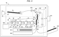
- FIG. 1 is a diagram illustrating an image forming apparatus 10 according to an embodiment.
- the image forming apparatus 10 is also referred to as a sheet processing apparatus or an image processing apparatus.
- the image forming apparatus 10 includes a control panel 13, a wireless tag communication device 201, and a printer unit 18.
- the printer unit 18 includes a control unit 100, paper feed cassettes 161 and 162, and the like.
- the control unit 100 is a control circuit or a controller configured to control the control panel 13, the wireless tag communication device 201, and the printer unit 18.
- the control unit 100 controls conveyance of a sheet in the printer unit 18.
- the control of the sheet conveyance includes controlling a sheet conveyance timing, a sheet stop position, a sheet conveyance speed, and the like.
- the control panel 13 includes an input key and a display unit.
- the input key receives input from a user.
- the display unit is a touch panel type.
- the display unit in such a case receives input from the user and displays information to the user according to the input(s).
- the control panel 13 displays items related to an operation of the image forming apparatus 10 on the display unit.
- the control panel 13 notifies the control unit 100 of the items selected by the user.
- the paper feed cassettes 161 and 162 accommodate sheets on which a wireless tag can be attached.
- the paper feed cassettes 161 and 162 can also accommodate a sheet on which a wireless tag is not attached.
- the sheet is provided with a wireless tag.
- a material such as paper or a plastic film is used for the sheet.
- the printer unit 18 performs an image forming operation. For example, the printer unit 18 forms an image indicated by image data on a sheet. In the following description, forming of an image on a sheet is simply referred to as printing.
- the printer unit 18 includes an intermediate transfer belt 21.
- the intermediate transfer belt 21 is supported by a driven roller 41, a backup roller 40, and the like.
- the printer unit 18 rotates the intermediate transfer belt 21 in a direction of arrow m shown in FIG. 1 .
- the printer unit 18 includes four sets of image forming stations 221, 222, 223, and 224.
- the image forming stations 221, 222, 223 and 224 are used for image forming of Y (yellow), M (magenta), C (cyan), and K (black), respectively.
- the image forming stations 221, 222, 223, and 224 are arranged below the intermediate transfer belt 21 along the intermediate transfer belt 21.
- the Y (yellow) image forming station 221 will be described as an example. Since the image forming stations 222, 223, and 224 have substantially the same configuration as the image forming station 221, detailed description thereof will be omitted.
- the image forming station 221 includes an electrostatic charger 26, an exposure scanning head 27, a developing device 28, and a photoreceptor cleaner 29.
- the electrostatic charger 26, the exposure scanning head 27, the developing device 28, and the photoreceptor cleaner 29 are arranged around a photoreceptor drum 24 that rotates in a direction of arrow n.
- the image forming station 221 includes a primary transfer roller 30.
- the primary transfer roller 30 faces the photoreceptor drum 24 via the intermediate transfer belt 21.
- the image forming station 221 charges the photoreceptor drum 24 with the electrostatic charger 26 and then selectively exposes the photoreceptor drum 24 with the exposure scanning head 27.
- the image forming station 221 thus forms an electrostatic latent image on the photoreceptor drum 24.
- the developing device 28 develops the electrostatic latent image on the photoreceptor drum 24 using a two-component developer formed of a toner and a carrier.
- the primary transfer roller 30 primarily transfers a toner image formed on the photoreceptor drum 24 onto the intermediate transfer belt 21.
- Each of the image forming stations 221, 222, 223, and 224 forms a color toner image on the intermediate transfer belt 21 by the primary transfer roller 30.
- the color toner image is formed by sequentially superimposing toner images of Y (yellow), M (magenta), C (cyan), and K (black) .
- the photoreceptor cleaner 29 removes the toner remaining on the photoreceptor drum 24 after the primary transfer.
- the printer unit 18 includes a secondary transfer roller 32.
- the secondary transfer roller 32 faces a backup roller 40 via the intermediate transfer belt 21.
- the secondary transfer roller 32 collectively and secondarily transfers the color toner image on the intermediate transfer belt 21 onto the sheet.
- the term "toner image” may be either a color toner image or a toner image of only one color.
- the toner image may be a toner image using decolorable toner.
- a conveyance path 331 is a conveyance path of the sheet extending from a confluence portion 441 to a branch portion 442.
- a conveyance path 332 is a conveyance path that passes through a double-sided printing device 38 and extends from the branch portion 442 to the confluence portion 441.
- a conveyance path 333 is a conveyance path of the sheet extending from the branch portion 442 to a paper discharge tray 20.
- the tip of the sheet picked up from a paper feed cassette 161, a paper feed cassette 162, or a manual feed tray 163 is abutted against a portion where two stopped registration rollers 31 are in contact with each other. An inclination of the sheet abutted against the registration roller 31 is corrected.
- the control unit 100 starts rotation of the registration roller 31 according to a position of the toner image on the rotating intermediate transfer belt 21 and moves the sheet to the secondary transfer roller 32.
- the control unit 100 controls the secondary transfer roller 32 to secondarily transfer the toner image formed on the intermediate transfer belt 21 to the sheet.
- the control unit 100 causes the sheet to be conveyed along the conveyance path 331 and controls a fixing device 34 to form and fix a toner image onto the sheet.
- the control unit 100 causes the sheet to be discharged via the conveyance path 333.
- control unit 100 causes the sheet on which an image formed to be conveyed through the conveyance path 333. After the entire sheet passes through the branch portion 442, the control unit 100 causes the sheet to be switched back and conveyed through the conveyance path 332. After that, the control unit 100 causes the sheet to be conveyed through the double-sided printing device 38, the confluence portion 441, the registration roller 31, and the conveyance path 331. Then, the control unit 100 controls the fixing device 34 to form and fix an image onto the back surface of the sheet. The control unit 100 causes the sheet to be discharged through the conveyance path 333.
- the wireless tag communication device 201 can communicate with the control unit 100.
- the wireless tag communication device 201 reads information from the wireless tag and writes information to the wireless tag by communicating with the wireless tag on the sheet.
- the wireless tag communication device 201 transmits a signal towards a direction of arrow k shown in FIG. 1 .
- the signal is specifically a modulated radio wave.
- Information is written to the wireless tag of the sheet by the signal transmitted by the wireless tag communication device 201.
- an electrostatic latent image is formed on the photoreceptor drum 24 by the exposure scanning head 27 before secondarily transferred by the secondary transfer roller 32.
- the electrostatic latent image formed on the photoreceptor drum 24 is primarily transferred to the intermediate transfer belt 21 as a toner image. Furthermore, the toner image primarily transferred to the intermediate transfer belt 21 is secondarily transferred to the wireless tag sheet conveyed to the registration roller 31.
- the image forming apparatus 10 includes the control unit 100, the control panel 13, the printer unit 18, and the wireless tag communication device 201.
- the control unit 100 includes a processing device 51 (e.g., a processor) and a storage device 52.
- the processing device 51 controls the control panel 13, the printer unit 18, and the wireless tag communication device 201 according to an image processing program stored in the storage device 52.
- the control unit 100 outputs conveyance start information indicating that the sheet conveyance has been started.
- the processing device 51 is, for example, a central processing unit (CPU), an application specific integrated circuit (ASIC), or the like.
- the storage device 52 is a read only memory (ROM), a random access memory (RAM), a hard disk drive (HDD), a solid-state drive (SSD), or the like.
- ROM read only memory
- RAM random access memory
- HDD hard disk drive
- SSD solid-state drive
- a data reception unit 53 receives, from a host, print data (for example, data described in a page description language) indicating an image to be printed.
- the host in this context is, for example, a personal computer (PC).
- the data reception unit 53 stores the print data received from the host in the storage device 52.
- An image data loading unit 54 converts the stored print data to data (for example, raster data) that can be printed by the printer unit 18 according to the printing parameters for the print data, and stores the converted data in the storage device 52.
- data for example, raster data
- the printer unit 18 includes the fixing device 34, the secondary transfer roller 32, and the developing device 28.
- the printer unit 18 forms an image on a sheet based on the converted data stored in the storage device 52.
- FIG. 3 is a diagram illustrating potential locations of a sheet in the image forming apparatus 10.
- a sheet Sb is a sheet placed in the paper feed cassette 161.
- a sheet Sc is a sheet placed on the paper discharge tray 20.
- a sheet Sd is a sheet placed on the manual feed tray 163.
- the sheet Sa is a sheet being conveyed along the conveyance path 331.
- the wireless tag is provided on each sheet.
- the sheet (hereinafter, also referred to as "target sheet”) on which information is to be written to the wireless tag is a sheet being conveyed along the conveyance path 331.
- the sheet Sa is the target sheet.
- the wireless tag communication device 201 transmits a signal towards the direction of arrow k. That is, the k-direction is a transmission direction of the signal transmitted by the wireless tag communication device 201. For that reason, the k-direction is also a propagation direction of the radio wave radiated by the wireless tag communication device 201.
- Each wireless tag that receives the signal operates according to the received signal.
- the wireless tag stores, for example, information indicated by the received signal.
- the wireless tag responds to, for example, the wireless tag communication device 201. Responding specifically means transmitting a signal.
- the wireless tag communication device 201 receives the signal transmitted from the wireless tag provided on each sheet.
- one of the wireless tags that receives the signal is the wireless tag provided on the sheet Sa.
- the sheet Sa is being conveyed.
- the wireless tag has a rectangular shape in a plane perpendicular to the k-direction having a longer side and a shorter side, and, when wavelengths of the radio waves are the same, a polarized wave whose polarization plane is parallel to the longer side (major axis) interacts more strongly with the wireless tag than a polarized wave whose polarization plane is perpendicular to the longer side.
- Stronger interaction in this context means that the probability that the radio wave passes through the wireless tag without generating a response is low or, alternatively, the probability that the radio wave reaching the wireless tag will be absorbed or reflected by the wireless tag is high.
- a radio wave whose polarization plane is parallel to the longer side of the wireless tag is desirably used for exchanging information with the wireless tag from the viewpoint of reducing power consumption and the frequency of communication errors.
- a communication error in this context means that information cannot be appropriately exchanged between the wireless tag communication device 201 and the wireless tag.
- FIG. 4 is a diagram illustrating relationships between a location of a wireless tag on a sheet and a conveyance direction of the sheet.
- each of wireless tags Ta, Tb, Tc, and Td is provided on the sheet Sa being conveyed along the conveyance path 331.
- the tag Ta is an example of the wireless tag provided on the sheet Sa so that the longer side of the tag Ta is perpendicular to the conveyance direction and perpendicular to the longer side of the paper surface.
- the tag Tb is an example of the wireless tag provided on the sheet Sa so that the longer side of the tag Tb is parallel to the conveyance direction and parallel to the longer side of the sheet Sa.
- the tag Tc is an example of the wireless tag provided on the sheet Sa so that the longer side of the tag Tc is perpendicular to the conveyance direction and parallel to the longer side of the sheet Sa.
- the tag Td is an example of the wireless tag provided on the sheet Sa so that the longer side of the tag Td is parallel to the conveyance direction and perpendicular to the longer side of the sheet Sa.
- FIG. 4 illustrates an example in which one wireless tag is arranged on one sheet, a plurality of radio tags may be arranged on one sheet.
- the sheet conveyance direction is, for example, a direction perpendicular to the k-direction in FIG. 3 and a direction from the bottom to the top on the paper surface of FIG. 3 . Since the wireless tag is provided on the sheet, the sheet conveyance direction is also the wireless tag conveyance direction.
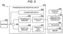
- FIG. 5 is a diagram illustrating the wireless tag communication device 201.
- the wireless tag communication device 201 includes an antenna 600, a wireless tag communication controller 501, a transmission and reception circuit 502, and an interface circuit 503.
- the antenna 600 transmits a signal.
- the antenna 600 receives an incoming signal.
- the carrier of the signal transmitted by the antenna 600 is a radio wave.
- the carrier of the signal received by the antenna 600 is a radio wave.
- the wireless tag communication controller 501 includes a processor 901 such as a CPU and a memory 902.
- the processor 901 of the wireless tag communication controller 501 executes a program(s) stored in the memory 902.
- the wireless tag communication controller 501 controls the operation of each circuit or unit included in the wireless tag communication device 201.
- a write threshold value (e.g., a signal strength value below which writing is not attempted)can be stored in the memory 902 in advance.
- the wireless tag communication controller 501 receives, for example, sheet conveyance start information.
- the wireless tag communication controller 501 controls transmission of a signal by controlling each circuit included in the wireless tag communication device 201, for example.
- the wireless tag communication controller 501 causes the signal received by the antenna 600 to be demodulated, for example, by controlling each circuit included in the wireless tag communication device 201.
- the wireless tag communication controller 501 measures, for example, the elapsed time since receiving the conveyance start information.
- the transmission and reception circuit 502 includes a modulation circuit 504, a transmission amplifier 505, a reception amplifier 506, a demodulation circuit 507, a circulator 508, and a changeover switch 509.
- the modulation circuit 504 modulates the radio wave radiated by the wireless tag communication device 201. More specifically, a voltage modulated by the control of the wireless tag communication controller 501 is applied to the modulation circuit 504, and the modulation circuit 504 generates a modulated current by application of the voltage. After the current generated by the modulation circuit 504 flows through the transmission amplifier 505, the antenna 600 transmits the radio wave. As described above, the radio wave is modulated by the modulation circuit 504 and radiated from the antenna 600, and therefore the transmitted radio wave from antenna 600 incorporates a signal to be transmitted by the wireless tag communication device 201.
- the transmission amplifier 505 controls intensity of the signal transmitted by the wireless tag communication device 201.
- the circulator 508 separates the signal transmitted by the antenna 600 from the signal received by the antenna 600.
- the changeover switch 509 switches a voltage application destination, that is, the target to which the current modulated by the modulation circuit 504 and amplified by the transmission amplifier 505 flows. Specifically, the changeover switch 509 switches a connection destination of the transmission amplifier 505 to one of power-feeding lines 641 and 642, which will be described later.
- the changeover switch 509 is a radio frequency (RF) switch such as a single pole double throw switch.
- RF radio frequency
- the reception amplifier 506 controls the intensity of the signal received by the antenna 600 to a predetermined intensity.
- the demodulation circuit 507 demodulates the signal received by the antenna 600.
- the interface circuit 503 is a circuit that electrically connects the wireless tag communication controller 501 and the control unit 100.
- FIG. 6 is a diagram illustrating a side view of the antenna 600.
- the antenna 600 is a microstrip antenna including a ground conductor plate 610, a dielectric substrate 620, and a radiation element 630.
- the ground conductor plate 610 is a grounded conductor.
- the dielectric substrate 620 is a dielectric material in contact with the ground conductor plate 610.
- the radiation element 630 is a conductor positioned on a side of the dielectric substrate 620 on which the ground conductor plate 610 is not disposed, and is a conductor in contact with the dielectric substrate 620.
- the radiation element 630 is connected to the power-feeding lines 641 and 642 penetrating the dielectric substrate 620 and the ground conductor plate 610.
- the power-feeding lines 641 and 642 are conductive wires.
- the power-feeding lines 641 and 642 are referred to as a power-feeding line 640.
- One end of the power-feeding line 640 not in contact with the radiation element 630 is connected to the changeover switch 509.
- a plane perpendicular to the k-direction is referred to as an XY-plane.
- Two vectors on the XY-plane and orthogonal to each other a referenced in this description.
- One vector that is perpendicular to the conveyance direction of the sheet as conveyed on the conveyance path 331 is referred to as an X-vector.
- Another vector that is perpendicular to the X-vector (e.g., parallel to the conveyance direction) is referred to as a Y-vector.
- Shapes of the surfaces of the radiation element 630 perpendicular to the k-direction are substantially the same regardless of the position along the k-direction.
- the length of the radiation element 630 in the k-direction is preferably shorter than the wavelength of the radio wave to be radiated by the radiation element 630, and particularly preferably less than one-fourth of the wavelength.
- FIG. 7 is a diagram illustrating a shape (hereinafter referred to as "radiation element shape") of the radiation element 630 in the XY-plane .
- the direction orthogonal to plane of the paper surface of FIG. 7 is parallel to the k-direction.
- a plane (hereinafter referred to as a "radiation element plane") surrounded by the radiation element shape has a first radiation region 701, a second radiation region 702, a third radiation region 703, and a fourth radiation region 704. That is, the first radiation region 701, the second radiation region 702, the third radiation region 703, and the fourth radiation region 704 are positioned in the same plane.
- the first radiation region 701 and the second radiation region 702 are regions having a shape that satisfies the condition that the length in the direction of the X-vector is longer than the length in the direction of the Y-vector.
- the third radiation region 703 and the fourth radiation region 704 are regions having a shape that satisfies the condition that the length in the direction of the Y-vector is longer than the length in the direction of the X-vector.
- the first radiation region 701 and the second radiation region 702 are regions having different lengths in the X-vector direction, and are regions that do not come into contact or overlap each other.
- the first radiation region 701 shares a part with the third radiation region 703 and the fourth radiation region 704.
- the second radiation region 702 shares a part with the third radiation region 703 and the fourth radiation region 704.
- the third radiation region 703 and the fourth radiation region 704 are regions having different lengths in the direction of the Y-vector, and are regions that do not come into contact or overlap each other.
- the third radiation region 703 shares a part thereof with the first radiation region 701 and the second radiation region 702.
- the fourth radiation region 704 shares a part thereof with the first radiation region 701 and the second radiation region 702.
- FIG. 8 is a top view illustrating the radiation element 630.
- the direction perpendicular to the paper surface of FIG. 8 is parallel to the k-direction.
- a region 711 in FIG. 8 corresponds to the first radiation region 701.
- a region 712 in FIG. 8 corresponds to the second radiation region 702.
- a region 721 in FIG. 8 corresponds to the third radiation region 703.
- a region 722 in FIG. 8 corresponds to the fourth radiation region 704.
- the radiation element plane may include the first radiation region 711, the second radiation region 712, the third radiation region 721, and the fourth radiation region 722, and may further include a first type additional region 713 and/or a second type additional region 723 in addition to the first radiation region 711, the second radiation region 712, the third radiation region 721, and the fourth radiation region 722. That is, the first radiation region 711, the second radiation region 712, the third radiation region 721, the fourth radiation region 722, the first type additional region 713, and the second type additional region 723 are positioned in the same plane.
- the first type additional region 713 is a region having a shape that satisfies the condition that the length in the direction of the X-vector is longer than the length in the direction of the Y-vector, and is a region different from the first radiation region 711 and the second radiation region 712.
- the first type additional region 713 is a region that does not come into contact with or overlap other first type additional regions.
- the first type additional region 713 is a region that does not come into contact with or overlap the first radiation region 711 and the second radiation region 712.
- the first type additional region 713 shares a part thereof with the third radiation region 721, the fourth radiation region 722, and the second type additional region 723.
- the second type additional region 723 is a region having a shape that satisfies the condition that the length in the direction of the Y-vector is longer than the length in the direction of the X-vector, and is a region different from the third radiation region 721 and the fourth radiation region 722.
- the second type additional region 723 is a region that does not come into contact with or overlap other second type additional regions.
- the second type additional region 723 is a region that does not come into contact with or overlap the third radiation region 721 and the fourth radiation region 722.
- the second type additional region 723 shares a part thereof with the first radiation region 711, the second radiation region 712, and the first type additional region 713.
- the number of first type additional regions 713 in the radiation element plane does not need to be one, and may be two or more.
- the number of second type additional regions 723 in the radiation element plane does not need to be one, and may be two or more.
- the radiation element 630 includes power-feeding points 731 and 732. More specifically, at the power-feeding point 731, the power-feeding line 641 and the radiation element 630 are in contact with each other, and at the power-feeding point 732, the power-feeding line 642 and the radiation element 630 are in contact with each other.
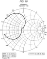
- FIGS. 9 and 10 are diagrams illustrating frequency response characteristics of the wireless tag communication device 201 regarding the radio wave transmitted and received by the wireless tag communication device 201, acquired through an experiment. More specifically, FIGS. 9 and 10 are diagrams the frequency response characteristics of the wireless tag communication device 201 regarding the radio wave transmitted and received by the wireless tag communication device 201 including the radiation element 630 of FIG. 8 . In particular, FIG. 10 illustrates the experimental results shown by the Smith chart. As the frequency response characteristics, values of the S parameter were measured.
- the conductivity was 5.8 ⁇ 10 7 (S/m) .
- the lengths of the regions 711, 712, and 713 in the direction of the X-vector were 77 mm, 72 mm, and 67 mm, respectively, and the lengths of the regions 711, 712, and 713 in the direction of the Y-vector were 10 mm, 21 mm, and 20 mm, respectively.
- the lengths of the regions 721, 722, and 723 in the direction of the X-vector were 10 mm, 21 mm, and 20 mm, respectively, and the lengths of the regions 721, 722, and 723 in the direction of the Y-vector were 67 mm, 72 mm, and 77 mm, respectively.
- the material of the dielectric substrate 620 was flame retardant type 4 (FR4), and a dielectric constant was 4.6.
- the length in the k-direction was 1.53 mm.
- the total length of the ground conductor plate 610 and the radiation element 630 in the k-direction was 0.07 mm.
- the plane of the dielectric substrate 620 in contact with the radiation element 630 had a length of 130 mm in the direction of the X-vector and a length of 130 mm in the direction of the Y-vector.
- the material of the ground conductor plate 610 was copper. For that reason, the conductivity was 5.8 ⁇ 10 7 (S/m).
- the length of the ground conductor plate 610 in the k-direction was 0.035 mm.
- the plane of the ground conductor plate 610 in contact with the dielectric substrate 620 had a length of 130 mm in the direction of the X-vector and a length of 130 mm in the direction of the Y-vector.
- FIGS. 9 and 10 illustrate shows a range of approximately 42 MHz in width centered on 920 MHz where S parameter S11 is -10 dB or less.
- comparative experiment a square patch antenna was used instead of the antenna 600.
- the square patch antennas used in the comparative experiment differed only in that the shape of the conductor radiating the radio wave in the XY-plane was square instead of the shape illustrated in FIG. 8 .
- the length of one side of the shape in the XY-plane of the square patch antenna used in the comparative experiment was 75 mm.
- FIG. 11 is a diagram illustrating frequency response characteristics of a wireless tag communication device having the comparative square patch antenna.
- FIG. 11 illustrates a range of approximately 10 MHz in width centered on 920 MHz where the S parameter S11 is -10 dB or less.
- FIGS. 9 , 10 and 11 illustrate that the antenna 600 is an antenna having a wider band than the square patch antenna.
- a radiation region in the radiation element 630 has a shape in which the length in the direction of a predetermined side is longer than the length in the direction of another side orthogonal to the predetermined side. That is, the shape of the radiation region has a longer side and a shorter side. Such a shape is similar to that of the antenna element.
- each radiation region radiates a polarized wave whose polarization plane is parallel to the longer side of the radiation region and having a resonance frequency determined by the length of the longer side .
- the resonance frequency is a frequency of a radio wave having a wavelength, a half of which is equal to the length of the longer side.
- the first radiation region 711 in FIG. 8 has a shape whose longer side is parallel to the X-axis and shorter side is parallel to the Y-axis. For that reason, the first radiation region 711 in FIG. 8 radiates the radio wave whose polarization plane is parallel to the X-axis and whose wavelength is equal to twice the length of the longer side of the first radiation region 711.
- the third radiation region 721 in FIG. 8 has a shape whose longer side is parallel to the Y-axis and shorter side is parallel to the X-axis. For that reason, the third radiation region 721 in FIG. 8 radiates the radio wave whose polarization plane is parallel to the Y-axis and whose wavelength is equal to twice the length of the longer side of the third radiation region 721.
- the radiation element 630 having a plurality of shapes of radiation regions can radiate a plurality of types of radio waves having different combinations of polarization planes and wavelengths. That is, the antenna 600 can emit a radio wave of a wider band than an antenna having only a single shape of radiation region such as a square patch antenna, and can radiate a plurality of radio waves having different polarization planes unlike the antenna having only one type of radiation region.
- adjacent radiation regions whose longer sides are parallel are electrically connected by a part of radiation regions whose longer sides cross the longer sides of the adjacent radiation regions.
- the first radiation region 711 and the second radiation region 712 are conducted by a part of the third radiation region 721, a part of the fourth radiation region 722, and a part of the second type additional radiation region 723 along the y-axis.
- a radiation region positioned in the space between adjacent radiation regions whose longer sides are parallel and which conducts the adjacent radiation regions is referred to as a conducting region.
- a part of the third radiation region 721 that conducts the first radiation region 711 and the second radiation region 712 along the y-axis is such a conducting portion.
- the first radiation region 711 and the second radiation region 712 can radiate not only the radio wave having a wavelength corresponding to the length of the longer side of each region but also the radio wave having a wavelength corresponding to the length of the longer side of a region obtained by adding the conducting portion to each region.
- the antenna 600 can radiate the radio waves in a wider band than an antenna having just a plurality of types of radiation regions in a state where the plurality of radiation regions spatially separated from each other.
- the antenna 600 can switch and radiate radio waves whose polarization planes are orthogonal to each other while having a structure in which a part of a plurality of radiation regions having longer sides extending towards different directions is shared. That is, the antenna 600 does not have a structure in which a plurality of radiation elements having longer sides extending towards different directions are spatially separated in order to radiate radio waves whose polarization planes are different. For that reason, the antenna 600 can reduce an occupancy area of the radiation element 630 for radiating radio waves having different polarization planes.
- the wireless tag communication device 201 configured as described above includes the antenna 600 capable of radiating a plurality of types of polarized waves having a plurality of polarization planes or different frequencies. For that reason, the probability that the polarized wave radiated by the wireless tag communication device 201 is received by the radio tag is higher than the probability that the polarized wave radiated by a conventional device that radiates only one type of polarized wave is received by the radio tag. For that reason, the wireless tag communication device 201 can reduce the chance that information cannot be exchanged with the wireless tag due to the difference in the type of the wireless tag.
- the image forming apparatus 10 configured in this way can reduce the chance that information cannot be exchanged with the wireless tag due to the difference in the type of the wireless tag.
- This is not limited to the image forming apparatus 10, but the same applies to another sheet processing apparatus provided with the wireless tag communication device 201.
- the image forming apparatus 10 may be a bar code printer used for managing a receipt and shipment of goods, or a reader that reads a sheet attached to goods displayed or sold in a retail store such as an apparel store.
- the sheet provided with the wireless tag is a sheet or a tag attached to goods.
- One end of the longer side of the first radiation region 711 and one end of the longer side of the second radiation region 712 do not necessarily need to be aligned as illustrated in FIG. 8 . That is, one end of the longer side of the first radiation region 711 and one end of the longer side of the second radiation region 712 may have a positional relationship as illustrated in FIG. 7 .
- one end of the longer side of one first type additional region and one ends of the longer sides of other first type additional regions do not necessarily need to be aligned.
- the ends are aligned, the effect that the gain is higher is obtained.
- the ends are not aligned, the number of sides of the radiation region increases and the power is dispersed. For that reason, when the ends are not aligned, power flowing in the longer side direction is reduced as compared with the case where the ends are aligned.
- the ends are aligned rather than the ends are not aligned.
- a distance between the radiation regions parallel to each other in the longer side direction is desirably within several mm.
- the same power flows through each radiation element, and the resonance frequency corresponding to each radiation region can be obtained at the same time. Therefore, a wider frequency band is supported by the wireless tag communication device 201.
- One end of the longer side of the third radiation region 721 and one end of the longer side of the fourth radiation region 722 do not necessarily need to be aligned as illustrated in FIG. 8 . That is, one end of the longer side of the third radiation region 721 and one end of the longer side of the fourth radiation region 722 may have a positional relationship as illustrated in FIG. 7 .
- one end of the longer side of one second type additional region and one ends of the longer sides of other second type additional regions do not necessarily need to be aligned.
- the ends are aligned, the effect that the gain is higher is obtained.
- the ends are not aligned, the number of sides of the radiation region increases and the power is dispersed. For that reason, when the ends are not aligned, power flowing in the longer side direction is reduced as compared with the case where the ends are aligned.
- the ends are aligned rather than the ends are not aligned.
- the third length may be substantially the same as or different from either the first length or the second length.
- the fourth length may be substantially the same as or different from one which is either the first length or the second length and is not substantially the same as the third length.
- the first length means the length of the longer side of the first radiation region 711.
- the second length means the length of the longer side of the second radiation region 712.
- the third length means the length of the longer side of the third radiation region 721.
- the fourth length means the length of the longer side of the fourth radiation region 722.
- the direction of the longer side of the radiation region does not necessarily need to be perpendicular or parallel to the sheet conveyance direction.
- the direction of the longer side of the radiation region may be perpendicular or parallel to a direction (hereinafter referred to as "reference direction") forming a predetermined angle with the sheet conveyance direction.
- reference direction a direction (hereinafter referred to as "reference direction") forming a predetermined angle with the sheet conveyance direction.
- reference direction forming a predetermined angle with the sheet conveyance direction.
- the X-axis direction in FIGS. 7 and 8 may be perpendicular to the reference direction
- the Y-axis direction in FIGS. 7 and 8 may be parallel to the reference direction.
- Whether the wireless tag communication device 201 exchanges information with the wireless tag using the power-feeding lines 641 or 642 may be determined in advance by a user or may be determined by the wireless tag communication device 201 by executing a predetermined process .
- the user makes such a determines in advance, for example, the user specifies one of the power-feeding lines 641 or 642, that radiates the polarized wave whose polarization plane is parallel to the direction of the wireless tag on the sheet to be processed, for information exchange.
- the wireless tag communication device 201 makes the determination, the following predetermined process is performed. For example, first, under the control of the wireless tag communication controller 501, the power-feeding lines 641, 642 to which the voltage is applied are switched at a predetermined cycle before exchanging information with the wireless tag. Then, each time the power-feeding lines 641, 642 are switched, radiation of the radio wave and intensity of a reflected wave by the wireless tag of the radio wave are measured.
- the wireless tag communication controller 501 determines the switching timing.
- the reflected wave is a radio wave radiated by the wireless tag.
- the wireless tag communication controller 501 measures the reflected wave.
- the wireless tag communication controller 501 ends the switching process at the timing when the reflected wave having predetermined intensity or higher is observed.
- the wireless tag communication controller 501 determines one of the power-feeding lines 641, 642, which was the target of voltage application at the time when the switching was completed, as the one to be used for exchanging information with the wireless tag.
- the functions of the image forming apparatus 10 and/or the wireless tag communication controller 501 described above may be realized by a computer.
- the functions may be implemented by a program(s) stored in a computer-readable recording medium, copied from the recording medium to a computer system, and executed by a processor or controller.
- a "computer system” as used herein includes an operating system (OS) and hardware such as peripheral devices.
- a "computer-readable recording medium” refers to a storage medium or device such as a portable medium such as a flexible disk, a magneto-optical disk, a ROM, or a CD-ROM, a hard disk built in the computer system, and the like.
- the "computer-readable recording medium” may be cloud-based system, a server, or client, and/or accessible via a communication line such as a network or the Internet or the like.
- a program as-described above may be a program for performing only some parts of the functions described above, and some or all the functions may be performed in conjunction with a program already recorded in the computer system.
- the risk that information cannot be exchanged with a wireless tag due to tag type incompatibilities, differences, or the like can be reduced by use of a wireless tag communication device corresponding to the wireless tag communication device 201.
Landscapes
- Engineering & Computer Science (AREA)
- Physics & Mathematics (AREA)
- Health & Medical Sciences (AREA)
- Toxicology (AREA)
- General Physics & Mathematics (AREA)
- Theoretical Computer Science (AREA)
- Computer Networks & Wireless Communication (AREA)
- Computer Vision & Pattern Recognition (AREA)
- Electromagnetism (AREA)
- Artificial Intelligence (AREA)
- General Health & Medical Sciences (AREA)
- Microelectronics & Electronic Packaging (AREA)
- Computer Hardware Design (AREA)
- Signal Processing (AREA)
- General Engineering & Computer Science (AREA)
- Near-Field Transmission Systems (AREA)
- Waveguide Aerials (AREA)
- Control Or Security For Electrophotography (AREA)
- Facsimiles In General (AREA)
- Variable-Direction Aerials And Aerial Arrays (AREA)
- Multimedia (AREA)
Abstract
Description
- This application is based upon and claims the benefit of priority from
Japanese Patent Application No. 2020-122404, filed July 16, 2020 - Embodiments described herein relate generally to a wireless tag communication device and a sheet processing apparatus.
- There is an image forming apparatus that forms an image on a sheet on which a wireless tag, such as a radio frequency identifier (RFID), is attached. Such an image forming apparatus has an antenna capable of transmitting and receiving a radio wave to exchange information with the wireless tag. The antenna radiates a radio wave that can be received the wireless tag. More particularly, the radio wave emitted from the antenna needs to have a polarization plane that matches a polarization plane that can be received by the wireless tag. In addition, the radio wave needs to have a frequency within a frequency band that can be received by the wireless tag.
- However, there are various different types of wireless tags that can be attached to a sheet. For example, the typical frequency band that can be received by a wireless tag may vary from country to country according to local standards or protocols. In such a case, an image forming apparatus capable of radiating radio waves only in a particular frequency band used in a specific country may not be able to communicate with a wireless tag used in another country. The differences in the types of usable wireless tags are not just dependent on the end-use country, and differences may also exist according to end-use application environments which may vary region to region even within a country. Such a problem associated with different potential wireless tag types may be more broadly found in any apparatus for processing a sheet or wireless tags.
- One of the objects of the present invention is to improve prior art techniques and overcome at least some of the prior art problems as for instance above illustrated.
- According to a first aspect of the present invention, it is provided a wireless tag communication device, comprising: an antenna with a plurality of radiation regions through from which a polarized radio wave is emitted and including a first radiation region extending along a first direction crossing a conveyance direction of a wireless tag along a conveyance mechanism and having a first length in the first direction, a second radiation region extending along the first direction and having a second length that is different from the first length in the first direction, a third radiation region extending along the conveyance direction and having a third length in the conveyance direction, and a fourth radiation region extending along the conveyance direction and having a fourth length that is different from the third length in the conveyance direction; and a controller configured to cause at least one of the first, second, third, or fourth radiation regions to emit a polarized wave towards the wireless tag, wherein each of the first and second radiation regions partially overlaps both the third radiation region and the fourth radiation region.
- Optionally, in the wireless tag communication according to the first aspect of the invention, each of the plurality of radiation regions has a rectangular shape.
- Optionally, in the wireless tag communication according to the first aspect of the invention, the plurality of radiation regions further include a fifth radiation region extending along the first direction and having a fifth length that is different from the first and second lengths in the first direction.
- Optionally, in the wireless tag communication according to the first aspect of the invention, the fifth radiation region partially overlaps both the third radiation region and the fourth radiation region.
- Optionally, in the wireless tag communication according to the first aspect of the invention, the plurality of radiation regions further include a sixth radiation region extending along the conveyance direction and having a sixth length that is different from the third and fourth lengths in the conveyance direction.
- Optionally, in the wireless tag communication according to the first aspect of the invention, the sixth radiation region partially overlaps each of the first, second, and fifth radiation regions.
- Optionally, in the wireless tag communication according to the first aspect of the invention, one side of each of the first and second radiation regions is aligned along the conveyance direction.
- Optionally, in the wireless tag communication according to the first aspect of the invention, one side of each of the third and fourth radiation regions is aligned along the first direction.
- Optionally, in the wireless tag communication according to the first aspect of the invention, the antenna further includes a first contact through which power is supplied, and the first contact is disposed on a portion of one of the plurality of radiation regions that overlaps another one of the plurality of radiation regions.
- Optionally, in the wireless tag communication according to the first aspect of the invention, the antenna further includes a second contact through which power is supplied, the second contact is disposed on a portion of different one of the plurality of radiation regions from the one of the plurality of radiation regions on which the first contact is disposed, and the second contact overlaps another one of the plurality of radiation regions different from the first contact.
- According to a second aspect of the invention, it is provided a sheet processing apparatus, comprising: a sheet conveyance path configured to convey a sheet having a wireless tag; and a wireless tag communication device configured to communicate with the wireless tag and including an antenna with a plurality of radiation regions from which a polarized radio wave is emitted and including a first radiation region extending along a first direction perpendicular to a conveyance direction of the wireless tag along the conveyance path and having a first length in the first direction, a second radiation region extending along the first direction and having a second length that is different from the first length in the first direction, a third radiation region extending along the conveyance direction and having a third length in the conveyance direction, and a fourth radiation region extending along the conveyance direction and having a fourth length that is different from the third length in the conveyance direction, and a controller configured to cause at least one of the first, second, third and, fourth radiation regions to emit a polarized wave toward the wireless tag, wherein each of the first and second radiation regions partially overlaps both the third radiation region and the fourth radiation region.
- Optionally, in the sheet processing apparatus according to the second aspect of the invention, each of the plurality of radiation regions has a rectangular shape.
- Optionally, in the sheet processing apparatus according to the second aspect of the invention, the plurality of radiation regions further include a fifth radiation region extending along the first direction and having a fifth length that is different from the first and second lengths in the first direction.
- Optionally, in the sheet processing apparatus according to the second aspect of the invention, the fifth radiation region partially overlaps both the third radiation and the fourth radiation region.
- Optionally, in the sheet processing apparatus according to the second aspect of the invention, the plurality of radiation regions further include a sixth radiation region extending along the conveyance direction and having a sixth length that is different from the third and fourth lengths in the conveyance direction.
- Optionally, in the sheet processing apparatus according to the second aspect of the invention, the sixth radiation region partially overlaps each of the first, second, and fifth radiation regions.
- Optionally, in the sheet processing apparatus according to the second aspect of the invention, one side of each of the first and second radiation regions is aligned along the conveyance direction.
- Optionally, in the sheet processing apparatus according to the second aspect of the invention, one side of each of the third and fourth radiation regions is aligned along the first direction.
- Optionally, in the sheet processing apparatus according to the second aspect of the invention, the antenna further includes a first contact through which power is supplied, and the first contact is disposed on a portion of one of the plurality of radiation regions that overlaps another one of the plurality of radiation regions.
- According to a third aspect of the invention, it is provided an antenna for a wireless tag communicating device configured to communicate with a wireless tag conveyed by a conveyance mechanism, the antenna comprising a plurality of radiation regions from which a polarized radio wave is emitted, the plurality of radiation regions including a first radiation region extending along a first direction perpendicular to a conveyance direction of the wireless tag and having a first length in the first direction, a second radiation region extending along the first direction and having a second length that is different from the first length in the first direction, a third radiation region extending along the conveyance direction and having a third length in the conveyance direction, and a fourth radiation region extending along the conveyance direction and having a fourth length that is different from the third length in the conveyance direction, wherein each of the first and second radiation regions partially overlaps both the third radiation region and the fourth radiation region.
-
-
FIG. 1 is a diagram illustrating an image forming apparatus according to an embodiment. -
FIG. 2 is a functional block diagram of an image forming apparatus. -
FIG. 3 is a diagram illustrating locations of a sheet in an image forming apparatus. -
FIG. 4 is a diagram illustrating relationships between a location of a wireless tag on a sheet and a conveyance direction of the sheet. -
FIG. 5 is a diagram illustrating a wireless tag communication device. -
FIG. 6 is a diagram illustrating a side view of an antenna. -
FIG. 7 is a diagram illustrating a shape of a radiation element. -
FIG. 8 is a top view illustrating a radiation element. -
FIG. 9 is a diagram illustrating frequency response characteristics of a wireless tag communication device. -
FIG. 10 is a diagram illustrating frequency response characteristics of a wireless tag communication device. -
Fig. 11 is a diagram illustrating frequency response characteristics of a comparative wireless tag communication device. - Embodiments provide a wireless tag communication device and a sheet processing apparatus that can exchange information with a wide variety wireless tag types.
- In general, according to one embodiment, a wireless tag communication device for communicating with a wireless tag being conveyed by a conveyance mechanism includes an antenna with a plurality of radiation regions or elements from which a polarized radio wave can be emitted. The radiation regions include a first radiation region extending along a first direction crossing a conveyance direction of the wireless tag and having a first length in the first direction, a second radiation region extending along the first direction and having a second length that is different from the first length in the first direction, a third radiation region extending along the conveyance direction and having a third length in the conveyance direction, and a fourth radiation region extending along the conveyance direction and having a fourth length that is different from the third length in the conveyance direction. The device further comprises a controller configured to cause at least one of the first, second, third and, fourth radiation regions to emit a polarized wave towards the wireless tag. Each of the first and second radiation regions partially overlaps both the third radiation region and the fourth radiation region.
- Hereinafter, a wireless tag communication device and a sheet processing apparatus according to one or more embodiments will be described with reference to the drawings.
- In the following description, the same reference numerals are used to identify like features. The duplicated description of repeated features may be omitted.
-
FIG. 1 is a diagram illustrating animage forming apparatus 10 according to an embodiment. Theimage forming apparatus 10 is also referred to as a sheet processing apparatus or an image processing apparatus. - In
FIG. 1 , theimage forming apparatus 10 includes acontrol panel 13, a wirelesstag communication device 201, and aprinter unit 18. Theprinter unit 18 includes acontrol unit 100,paper feed cassettes control unit 100 is a control circuit or a controller configured to control thecontrol panel 13, the wirelesstag communication device 201, and theprinter unit 18. Thecontrol unit 100 controls conveyance of a sheet in theprinter unit 18. The control of the sheet conveyance includes controlling a sheet conveyance timing, a sheet stop position, a sheet conveyance speed, and the like. - The
control panel 13 includes an input key and a display unit. For example, the input key receives input from a user. For example, the display unit is a touch panel type. The display unit in such a case receives input from the user and displays information to the user according to the input(s). For example, thecontrol panel 13 displays items related to an operation of theimage forming apparatus 10 on the display unit. Thecontrol panel 13 notifies thecontrol unit 100 of the items selected by the user. - The
paper feed cassettes paper feed cassettes - The
printer unit 18 performs an image forming operation. For example, theprinter unit 18 forms an image indicated by image data on a sheet. In the following description, forming of an image on a sheet is simply referred to as printing. Theprinter unit 18 includes anintermediate transfer belt 21. Theintermediate transfer belt 21 is supported by a drivenroller 41, abackup roller 40, and the like. Theprinter unit 18 rotates theintermediate transfer belt 21 in a direction of arrow m shown inFIG. 1 . - The
printer unit 18 includes four sets ofimage forming stations image forming stations image forming stations intermediate transfer belt 21 along theintermediate transfer belt 21. - Hereinafter, among the
image forming stations image forming station 221 will be described as an example. Since theimage forming stations image forming station 221, detailed description thereof will be omitted. - The
image forming station 221 includes anelectrostatic charger 26, anexposure scanning head 27, a developingdevice 28, and aphotoreceptor cleaner 29. Theelectrostatic charger 26, theexposure scanning head 27, the developingdevice 28, and thephotoreceptor cleaner 29 are arranged around aphotoreceptor drum 24 that rotates in a direction of arrow n. - The
image forming station 221 includes aprimary transfer roller 30. Theprimary transfer roller 30 faces thephotoreceptor drum 24 via theintermediate transfer belt 21. - The
image forming station 221 charges thephotoreceptor drum 24 with theelectrostatic charger 26 and then selectively exposes thephotoreceptor drum 24 with theexposure scanning head 27. Theimage forming station 221 thus forms an electrostatic latent image on thephotoreceptor drum 24. The developingdevice 28 develops the electrostatic latent image on thephotoreceptor drum 24 using a two-component developer formed of a toner and a carrier. - The
primary transfer roller 30 primarily transfers a toner image formed on thephotoreceptor drum 24 onto theintermediate transfer belt 21. Each of theimage forming stations intermediate transfer belt 21 by theprimary transfer roller 30. The color toner image is formed by sequentially superimposing toner images of Y (yellow), M (magenta), C (cyan), and K (black) . Thephotoreceptor cleaner 29 removes the toner remaining on thephotoreceptor drum 24 after the primary transfer. - The
printer unit 18 includes asecondary transfer roller 32. Thesecondary transfer roller 32 faces abackup roller 40 via theintermediate transfer belt 21. Thesecondary transfer roller 32 collectively and secondarily transfers the color toner image on theintermediate transfer belt 21 onto the sheet. In the following description, the term "toner image" may be either a color toner image or a toner image of only one color. The toner image may be a toner image using decolorable toner. - A
conveyance path 331 is a conveyance path of the sheet extending from aconfluence portion 441 to abranch portion 442. Aconveyance path 332 is a conveyance path that passes through a double-sided printing device 38 and extends from thebranch portion 442 to theconfluence portion 441. Aconveyance path 333 is a conveyance path of the sheet extending from thebranch portion 442 to apaper discharge tray 20. - The tip of the sheet picked up from a
paper feed cassette 161, apaper feed cassette 162, or amanual feed tray 163 is abutted against a portion where two stoppedregistration rollers 31 are in contact with each other. An inclination of the sheet abutted against theregistration roller 31 is corrected. Thecontrol unit 100 starts rotation of theregistration roller 31 according to a position of the toner image on the rotatingintermediate transfer belt 21 and moves the sheet to thesecondary transfer roller 32. Thecontrol unit 100 controls thesecondary transfer roller 32 to secondarily transfer the toner image formed on theintermediate transfer belt 21 to the sheet. Thecontrol unit 100 causes the sheet to be conveyed along theconveyance path 331 and controls a fixingdevice 34 to form and fix a toner image onto the sheet. Thecontrol unit 100 causes the sheet to be discharged via theconveyance path 333. - In the case of double-sided printing, the
control unit 100 causes the sheet on which an image formed to be conveyed through theconveyance path 333. After the entire sheet passes through thebranch portion 442, thecontrol unit 100 causes the sheet to be switched back and conveyed through theconveyance path 332. After that, thecontrol unit 100 causes the sheet to be conveyed through the double-sided printing device 38, theconfluence portion 441, theregistration roller 31, and theconveyance path 331. Then, thecontrol unit 100 controls the fixingdevice 34 to form and fix an image onto the back surface of the sheet. Thecontrol unit 100 causes the sheet to be discharged through theconveyance path 333. - The wireless
tag communication device 201 can communicate with thecontrol unit 100. The wirelesstag communication device 201 reads information from the wireless tag and writes information to the wireless tag by communicating with the wireless tag on the sheet. The wirelesstag communication device 201 transmits a signal towards a direction of arrow k shown inFIG. 1 . The signal is specifically a modulated radio wave. Information is written to the wireless tag of the sheet by the signal transmitted by the wirelesstag communication device 201. - When an image is formed in the
printer unit 18, an electrostatic latent image is formed on thephotoreceptor drum 24 by theexposure scanning head 27 before secondarily transferred by thesecondary transfer roller 32. The electrostatic latent image formed on thephotoreceptor drum 24 is primarily transferred to theintermediate transfer belt 21 as a toner image. Furthermore, the toner image primarily transferred to theintermediate transfer belt 21 is secondarily transferred to the wireless tag sheet conveyed to theregistration roller 31. - Next, a functional block diagram of the
image forming apparatus 10 will be described with reference toFIG. 2 . - In
FIG. 2 , theimage forming apparatus 10 includes thecontrol unit 100, thecontrol panel 13, theprinter unit 18, and the wirelesstag communication device 201. - The
control unit 100 includes a processing device 51 (e.g., a processor) and astorage device 52. Theprocessing device 51 controls thecontrol panel 13, theprinter unit 18, and the wirelesstag communication device 201 according to an image processing program stored in thestorage device 52. Thecontrol unit 100 outputs conveyance start information indicating that the sheet conveyance has been started. - The
processing device 51 is, for example, a central processing unit (CPU), an application specific integrated circuit (ASIC), or the like. - The
storage device 52 is a read only memory (ROM), a random access memory (RAM), a hard disk drive (HDD), a solid-state drive (SSD), or the like. - A
data reception unit 53 receives, from a host, print data (for example, data described in a page description language) indicating an image to be printed. The host in this context is, for example, a personal computer (PC). Thedata reception unit 53 stores the print data received from the host in thestorage device 52. - An image
data loading unit 54 converts the stored print data to data (for example, raster data) that can be printed by theprinter unit 18 according to the printing parameters for the print data, and stores the converted data in thestorage device 52. - The
printer unit 18 includes the fixingdevice 34, thesecondary transfer roller 32, and the developingdevice 28. Theprinter unit 18 forms an image on a sheet based on the converted data stored in thestorage device 52. -
FIG. 3 is a diagram illustrating potential locations of a sheet in theimage forming apparatus 10. InFIG. 3 , a sheet Sb is a sheet placed in thepaper feed cassette 161. A sheet Sc is a sheet placed on thepaper discharge tray 20. A sheet Sd is a sheet placed on themanual feed tray 163. - The sheet Sa is a sheet being conveyed along the
conveyance path 331. The wireless tag is provided on each sheet. - In
FIG. 3 , the sheet (hereinafter, also referred to as "target sheet") on which information is to be written to the wireless tag is a sheet being conveyed along theconveyance path 331. Thus, the sheet Sa is the target sheet. - In the state illustrated in
FIG. 3 , the wirelesstag communication device 201 transmits a signal towards the direction of arrow k. That is, the k-direction is a transmission direction of the signal transmitted by the wirelesstag communication device 201. For that reason, the k-direction is also a propagation direction of the radio wave radiated by the wirelesstag communication device 201. - Each wireless tag that receives the signal operates according to the received signal. The wireless tag stores, for example, information indicated by the received signal. The wireless tag responds to, for example, the wireless
tag communication device 201. Responding specifically means transmitting a signal. The wirelesstag communication device 201 receives the signal transmitted from the wireless tag provided on each sheet. In the case ofFIG. 3 , one of the wireless tags that receives the signal is the wireless tag provided on the sheet Sa. InFIG. 3 , the sheet Sa is being conveyed. - The wireless tag has a rectangular shape in a plane perpendicular to the k-direction having a longer side and a shorter side, and, when wavelengths of the radio waves are the same, a polarized wave whose polarization plane is parallel to the longer side (major axis) interacts more strongly with the wireless tag than a polarized wave whose polarization plane is perpendicular to the longer side.
- Stronger interaction in this context means that the probability that the radio wave passes through the wireless tag without generating a response is low or, alternatively, the probability that the radio wave reaching the wireless tag will be absorbed or reflected by the wireless tag is high. For this reason, in the wireless
tag communication device 201, a radio wave whose polarization plane is parallel to the longer side of the wireless tag is desirably used for exchanging information with the wireless tag from the viewpoint of reducing power consumption and the frequency of communication errors. A communication error in this context means that information cannot be appropriately exchanged between the wirelesstag communication device 201 and the wireless tag. -
FIG. 4 is a diagram illustrating relationships between a location of a wireless tag on a sheet and a conveyance direction of the sheet. InFIG. 4 , each of wireless tags Ta, Tb, Tc, and Td is provided on the sheet Sa being conveyed along theconveyance path 331. The tag Ta is an example of the wireless tag provided on the sheet Sa so that the longer side of the tag Ta is perpendicular to the conveyance direction and perpendicular to the longer side of the paper surface. The tag Tb is an example of the wireless tag provided on the sheet Sa so that the longer side of the tag Tb is parallel to the conveyance direction and parallel to the longer side of the sheet Sa. The tag Tc is an example of the wireless tag provided on the sheet Sa so that the longer side of the tag Tc is perpendicular to the conveyance direction and parallel to the longer side of the sheet Sa. The tag Td is an example of the wireless tag provided on the sheet Sa so that the longer side of the tag Td is parallel to the conveyance direction and perpendicular to the longer side of the sheet Sa. AlthoughFIG. 4 illustrates an example in which one wireless tag is arranged on one sheet, a plurality of radio tags may be arranged on one sheet. - The sheet conveyance direction is, for example, a direction perpendicular to the k-direction in
FIG. 3 and a direction from the bottom to the top on the paper surface ofFIG. 3 . Since the wireless tag is provided on the sheet, the sheet conveyance direction is also the wireless tag conveyance direction. -
FIG. 5 is a diagram illustrating the wirelesstag communication device 201. - The wireless
tag communication device 201 includes anantenna 600, a wirelesstag communication controller 501, a transmission andreception circuit 502, and aninterface circuit 503. - The
antenna 600 transmits a signal. Theantenna 600 receives an incoming signal. The carrier of the signal transmitted by theantenna 600 is a radio wave. The carrier of the signal received by theantenna 600 is a radio wave. - The wireless
tag communication controller 501 includes aprocessor 901 such as a CPU and amemory 902. Theprocessor 901 of the wirelesstag communication controller 501 executes a program(s) stored in thememory 902. The wirelesstag communication controller 501 controls the operation of each circuit or unit included in the wirelesstag communication device 201. A write threshold value (e.g., a signal strength value below which writing is not attempted)can be stored in thememory 902 in advance. - The wireless
tag communication controller 501 receives, for example, sheet conveyance start information. The wirelesstag communication controller 501 controls transmission of a signal by controlling each circuit included in the wirelesstag communication device 201, for example. The wirelesstag communication controller 501 causes the signal received by theantenna 600 to be demodulated, for example, by controlling each circuit included in the wirelesstag communication device 201. The wirelesstag communication controller 501 measures, for example, the elapsed time since receiving the conveyance start information. - The transmission and
reception circuit 502 includes amodulation circuit 504, atransmission amplifier 505, areception amplifier 506, ademodulation circuit 507, acirculator 508, and achangeover switch 509. - The
modulation circuit 504 modulates the radio wave radiated by the wirelesstag communication device 201. More specifically, a voltage modulated by the control of the wirelesstag communication controller 501 is applied to themodulation circuit 504, and themodulation circuit 504 generates a modulated current by application of the voltage. After the current generated by themodulation circuit 504 flows through thetransmission amplifier 505, theantenna 600 transmits the radio wave. As described above, the radio wave is modulated by themodulation circuit 504 and radiated from theantenna 600, and therefore the transmitted radio wave fromantenna 600 incorporates a signal to be transmitted by the wirelesstag communication device 201. - The
transmission amplifier 505 controls intensity of the signal transmitted by the wirelesstag communication device 201. Thecirculator 508 separates the signal transmitted by theantenna 600 from the signal received by theantenna 600. - The
changeover switch 509 switches a voltage application destination, that is, the target to which the current modulated by themodulation circuit 504 and amplified by thetransmission amplifier 505 flows. Specifically, thechangeover switch 509 switches a connection destination of thetransmission amplifier 505 to one of power-feedinglines changeover switch 509 is a radio frequency (RF) switch such as a single pole double throw switch. The operation of thechangeover switch 509 is controlled by the wirelesstag communication controller 501. Thechangeover switch 509 switches, under the control of the wirelesstag communication controller 501, the voltage application destination. - The
reception amplifier 506 controls the intensity of the signal received by theantenna 600 to a predetermined intensity. Thedemodulation circuit 507 demodulates the signal received by theantenna 600. - The
interface circuit 503 is a circuit that electrically connects the wirelesstag communication controller 501 and thecontrol unit 100. -
FIG. 6 is a diagram illustrating a side view of theantenna 600. Theantenna 600 is a microstrip antenna including aground conductor plate 610, adielectric substrate 620, and aradiation element 630. Theground conductor plate 610 is a grounded conductor. Thedielectric substrate 620 is a dielectric material in contact with theground conductor plate 610. - The
radiation element 630 is a conductor positioned on a side of thedielectric substrate 620 on which theground conductor plate 610 is not disposed, and is a conductor in contact with thedielectric substrate 620. Theradiation element 630 is connected to the power-feedinglines dielectric substrate 620 and theground conductor plate 610. The power-feedinglines lines radiation element 630 radiates the radio wave generated by the current generated by the applied voltage. The radiated radio wave is a signal. A wave vector of the radio wave radiated by theradiation element 630 is the vector directed towards the k-direction. Hereinafter, when the power-feeding line 641 and the power-feeding line 642 are not distinguished, the power-feedinglines feeding line 640. One end of the power-feeding line 640 not in contact with theradiation element 630 is connected to thechangeover switch 509. - For the sake of simplicity, a plane perpendicular to the k-direction is referred to as an XY-plane. Two vectors on the XY-plane and orthogonal to each other a referenced in this description. One vector that is perpendicular to the conveyance direction of the sheet as conveyed on the
conveyance path 331 is referred to as an X-vector. Another vector that is perpendicular to the X-vector (e.g., parallel to the conveyance direction) is referred to as a Y-vector. - Shapes of the surfaces of the
radiation element 630 perpendicular to the k-direction are substantially the same regardless of the position along the k-direction. The length of theradiation element 630 in the k-direction is preferably shorter than the wavelength of the radio wave to be radiated by theradiation element 630, and particularly preferably less than one-fourth of the wavelength. -
FIG. 7 is a diagram illustrating a shape (hereinafter referred to as "radiation element shape") of theradiation element 630 in the XY-plane . The direction orthogonal to plane of the paper surface ofFIG. 7 is parallel to the k-direction. - A plane (hereinafter referred to as a "radiation element plane") surrounded by the radiation element shape has a
first radiation region 701, asecond radiation region 702, athird radiation region 703, and afourth radiation region 704. That is, thefirst radiation region 701, thesecond radiation region 702, thethird radiation region 703, and thefourth radiation region 704 are positioned in the same plane. Thefirst radiation region 701 and thesecond radiation region 702 are regions having a shape that satisfies the condition that the length in the direction of the X-vector is longer than the length in the direction of the Y-vector. Thethird radiation region 703 and thefourth radiation region 704 are regions having a shape that satisfies the condition that the length in the direction of the Y-vector is longer than the length in the direction of the X-vector. - The
first radiation region 701 and thesecond radiation region 702 are regions having different lengths in the X-vector direction, and are regions that do not come into contact or overlap each other. Thefirst radiation region 701 shares a part with thethird radiation region 703 and thefourth radiation region 704. Thesecond radiation region 702 shares a part with thethird radiation region 703 and thefourth radiation region 704. - The
third radiation region 703 and thefourth radiation region 704 are regions having different lengths in the direction of the Y-vector, and are regions that do not come into contact or overlap each other. Thethird radiation region 703 shares a part thereof with thefirst radiation region 701 and thesecond radiation region 702. Thefourth radiation region 704 shares a part thereof with thefirst radiation region 701 and thesecond radiation region 702. -
FIG. 8 is a top view illustrating theradiation element 630. The direction perpendicular to the paper surface ofFIG. 8 is parallel to the k-direction. - A
region 711 inFIG. 8 corresponds to thefirst radiation region 701. Aregion 712 inFIG. 8 corresponds to thesecond radiation region 702. Aregion 721 inFIG. 8 corresponds to thethird radiation region 703. Aregion 722 inFIG. 8 corresponds to thefourth radiation region 704. - In
FIG. 8 , the radiation element plane may include thefirst radiation region 711, thesecond radiation region 712, thethird radiation region 721, and thefourth radiation region 722, and may further include a first typeadditional region 713 and/or a second typeadditional region 723 in addition to thefirst radiation region 711, thesecond radiation region 712, thethird radiation region 721, and thefourth radiation region 722. That is, thefirst radiation region 711, thesecond radiation region 712, thethird radiation region 721, thefourth radiation region 722, the first typeadditional region 713, and the second typeadditional region 723 are positioned in the same plane. - The first type
additional region 713 is a region having a shape that satisfies the condition that the length in the direction of the X-vector is longer than the length in the direction of the Y-vector, and is a region different from thefirst radiation region 711 and thesecond radiation region 712. The first typeadditional region 713 is a region that does not come into contact with or overlap other first type additional regions. The first typeadditional region 713 is a region that does not come into contact with or overlap thefirst radiation region 711 and thesecond radiation region 712. The first typeadditional region 713 shares a part thereof with thethird radiation region 721, thefourth radiation region 722, and the second typeadditional region 723. - The second type
additional region 723 is a region having a shape that satisfies the condition that the length in the direction of the Y-vector is longer than the length in the direction of the X-vector, and is a region different from thethird radiation region 721 and thefourth radiation region 722. The second typeadditional region 723 is a region that does not come into contact with or overlap other second type additional regions. The second typeadditional region 723 is a region that does not come into contact with or overlap thethird radiation region 721 and thefourth radiation region 722. The second typeadditional region 723 shares a part thereof with thefirst radiation region 711, thesecond radiation region 712, and the first typeadditional region 713. - The number of first type
additional regions 713 in the radiation element plane does not need to be one, and may be two or more. The number of second typeadditional regions 723 in the radiation element plane does not need to be one, and may be two or more. - The
radiation element 630 includes power-feedingpoints feeding point 731, the power-feeding line 641 and theradiation element 630 are in contact with each other, and at the power-feeding point 732, the power-feeding line 642 and theradiation element 630 are in contact with each other. -
FIGS. 9 and10 are diagrams illustrating frequency response characteristics of the wirelesstag communication device 201 regarding the radio wave transmitted and received by the wirelesstag communication device 201, acquired through an experiment. More specifically,FIGS. 9 and10 are diagrams the frequency response characteristics of the wirelesstag communication device 201 regarding the radio wave transmitted and received by the wirelesstag communication device 201 including theradiation element 630 ofFIG. 8 . In particular,FIG. 10 illustrates the experimental results shown by the Smith chart. As the frequency response characteristics, values of the S parameter were measured. - In the experiment, a material of the
radiation element 630 was copper. For that reason, the conductivity was 5.8×10⁷ (S/m) . In the experiment, the lengths of theregions regions regions regions - In the experiment, the material of the
dielectric substrate 620 was flame retardant type 4 (FR4), and a dielectric constant was 4.6. The length in the k-direction was 1.53 mm. The total length of theground conductor plate 610 and theradiation element 630 in the k-direction was 0.07 mm. In the experiment, the plane of thedielectric substrate 620 in contact with theradiation element 630 had a length of 130 mm in the direction of the X-vector and a length of 130 mm in the direction of the Y-vector. - In the experiment, the material of the
ground conductor plate 610 was copper. For that reason, the conductivity was 5.8×10⁷ (S/m). In the experiment, the length of theground conductor plate 610 in the k-direction was 0.035 mm. In the experiment, the plane of theground conductor plate 610 in contact with thedielectric substrate 620 had a length of 130 mm in the direction of the X-vector and a length of 130 mm in the direction of the Y-vector. -
FIGS. 9 and10 illustrate shows a range of approximately 42 MHz in width centered on 920 MHz where S parameter S11 is -10 dB or less. - Next, the results of an experiment (hereinafter referred to as "comparative experiment") for comparison with the results of the experiment in
FIGS. 9 and10 will be described with reference toFIG. 11 . In the comparative experiment, a square patch antenna was used instead of theantenna 600. The square patch antennas used in the comparative experiment differed only in that the shape of the conductor radiating the radio wave in the XY-plane was square instead of the shape illustrated inFIG. 8 . The length of one side of the shape in the XY-plane of the square patch antenna used in the comparative experiment was 75 mm. -
FIG. 11 is a diagram illustrating frequency response characteristics of a wireless tag communication device having the comparative square patch antenna.FIG. 11 illustrates a range of approximately 10 MHz in width centered on 920 MHz where the S parameter S11 is -10 dB or less. - The results shown in
FIGS. 9 ,10 and11 illustrate that theantenna 600 is an antenna having a wider band than the square patch antenna. - Here, the reason why the
antenna 600 has a wider band than the square patch antenna will be explained. Hereinafter, for the sake of simplicity, when thefirst radiation region 711, thesecond radiation region 712, thethird radiation region 721, thefourth radiation region 722, the first typeadditional region 713, and the second typeadditional region 723 are not distinguished, these regions are referred to as radiation regions. A radiation region in theradiation element 630 has a shape in which the length in the direction of a predetermined side is longer than the length in the direction of another side orthogonal to the predetermined side. That is, the shape of the radiation region has a longer side and a shorter side. Such a shape is similar to that of the antenna element. For that reason, each radiation region radiates a polarized wave whose polarization plane is parallel to the longer side of the radiation region and having a resonance frequency determined by the length of the longer side . Specifically, the resonance frequency is a frequency of a radio wave having a wavelength, a half of which is equal to the length of the longer side. - For example, the
first radiation region 711 inFIG. 8 has a shape whose longer side is parallel to the X-axis and shorter side is parallel to the Y-axis. For that reason, thefirst radiation region 711 inFIG. 8 radiates the radio wave whose polarization plane is parallel to the X-axis and whose wavelength is equal to twice the length of the longer side of thefirst radiation region 711. For example, thethird radiation region 721 inFIG. 8 has a shape whose longer side is parallel to the Y-axis and shorter side is parallel to the X-axis. For that reason, thethird radiation region 721 inFIG. 8 radiates the radio wave whose polarization plane is parallel to the Y-axis and whose wavelength is equal to twice the length of the longer side of thethird radiation region 721. - For that reason, the
radiation element 630 having a plurality of shapes of radiation regions can radiate a plurality of types of radio waves having different combinations of polarization planes and wavelengths. That is, theantenna 600 can emit a radio wave of a wider band than an antenna having only a single shape of radiation region such as a square patch antenna, and can radiate a plurality of radio waves having different polarization planes unlike the antenna having only one type of radiation region. - In the
radiation element 630, adjacent radiation regions whose longer sides are parallel are electrically connected by a part of radiation regions whose longer sides cross the longer sides of the adjacent radiation regions. For example, inFIG. 8 , thefirst radiation region 711 and thesecond radiation region 712 are conducted by a part of thethird radiation region 721, a part of thefourth radiation region 722, and a part of the second typeadditional radiation region 723 along the y-axis. Hereinafter, a radiation region positioned in the space between adjacent radiation regions whose longer sides are parallel and which conducts the adjacent radiation regions is referred to as a conducting region. For example, a part of thethird radiation region 721 that conducts thefirst radiation region 711 and thesecond radiation region 712 along the y-axis is such a conducting portion. - For that reason, the
first radiation region 711 and thesecond radiation region 712 can radiate not only the radio wave having a wavelength corresponding to the length of the longer side of each region but also the radio wave having a wavelength corresponding to the length of the longer side of a region obtained by adding the conducting portion to each region. For that reason, theantenna 600 can radiate the radio waves in a wider band than an antenna having just a plurality of types of radiation regions in a state where the plurality of radiation regions spatially separated from each other. - Furthermore, the
antenna 600 can switch and radiate radio waves whose polarization planes are orthogonal to each other while having a structure in which a part of a plurality of radiation regions having longer sides extending towards different directions is shared. That is, theantenna 600 does not have a structure in which a plurality of radiation elements having longer sides extending towards different directions are spatially separated in order to radiate radio waves whose polarization planes are different. For that reason, theantenna 600 can reduce an occupancy area of theradiation element 630 for radiating radio waves having different polarization planes. - The wireless
tag communication device 201 configured as described above includes theantenna 600 capable of radiating a plurality of types of polarized waves having a plurality of polarization planes or different frequencies. For that reason, the probability that the polarized wave radiated by the wirelesstag communication device 201 is received by the radio tag is higher than the probability that the polarized wave radiated by a conventional device that radiates only one type of polarized wave is received by the radio tag. For that reason, the wirelesstag communication device 201 can reduce the chance that information cannot be exchanged with the wireless tag due to the difference in the type of the wireless tag. - For that reason, the
image forming apparatus 10 configured in this way can reduce the chance that information cannot be exchanged with the wireless tag due to the difference in the type of the wireless tag. This is not limited to theimage forming apparatus 10, but the same applies to another sheet processing apparatus provided with the wirelesstag communication device 201. - The
image forming apparatus 10 may be a bar code printer used for managing a receipt and shipment of goods, or a reader that reads a sheet attached to goods displayed or sold in a retail store such as an apparel store. In such a case, the sheet provided with the wireless tag is a sheet or a tag attached to goods. - One end of the longer side of the
first radiation region 711 and one end of the longer side of thesecond radiation region 712 do not necessarily need to be aligned as illustrated inFIG. 8 . That is, one end of the longer side of thefirst radiation region 711 and one end of the longer side of thesecond radiation region 712 may have a positional relationship as illustrated inFIG. 7 . The same applies to the first typeadditional region 713. That is, one end of the longer side of thefirst radiation region 711 and one end of the longer side of the first typeadditional region 713 do not necessarily need to be aligned, and one end of the longer side of thesecond radiation region 712 and one end of the longer side of the first typeadditional region 713 do not necessarily need to be aligned. - When a plurality of first type additional regions exist, one end of the longer side of one first type additional region and one ends of the longer sides of other first type additional regions do not necessarily need to be aligned. However, when the ends are aligned, the effect that the gain is higher is obtained. When the ends are not aligned, the number of sides of the radiation region increases and the power is dispersed. For that reason, when the ends are not aligned, power flowing in the longer side direction is reduced as compared with the case where the ends are aligned. As described above, since the radiation region radiates the radio wave having the resonance frequency determined by the length of the longer side, the greater the power flowing in the longer side direction, the higher the gain can be obtained. For that reason, desirably, the ends are aligned rather than the ends are not aligned.
- A distance between the radiation regions parallel to each other in the longer side direction is desirably within several mm. When the distance is within several mm, the same power flows through each radiation element, and the resonance frequency corresponding to each radiation region can be obtained at the same time. Therefore, a wider frequency band is supported by the wireless
tag communication device 201. - One end of the longer side of the
third radiation region 721 and one end of the longer side of thefourth radiation region 722 do not necessarily need to be aligned as illustrated inFIG. 8 . That is, one end of the longer side of thethird radiation region 721 and one end of the longer side of thefourth radiation region 722 may have a positional relationship as illustrated inFIG. 7 . The same applies to the second typeadditional region 723. That is, one end of the longer side of thethird radiation region 721 and one end of the longer side of the second typeadditional region 723 do not necessarily need to be aligned, and one end of the longer side of thefourth radiation region 722 and one end of the longer side of the second typeadditional region 723 do not necessarily need to be aligned. When a plurality of second type additional regions exist, one end of the longer side of one second type additional region and one ends of the longer sides of other second type additional regions do not necessarily need to be aligned. However, when the ends are aligned, the effect that the gain is higher is obtained. When the ends are not aligned, the number of sides of the radiation region increases and the power is dispersed. For that reason, when the ends are not aligned, power flowing in the longer side direction is reduced as compared with the case where the ends are aligned. As described above, since the radiation region radiates the radio wave having the resonance frequency determined by the length of the longer side, the greater the power flowing in the longer side direction, the higher the gain can be obtained. For that reason, desirably, the ends are aligned rather than the ends are not aligned. - The third length may be substantially the same as or different from either the first length or the second length. The fourth length may be substantially the same as or different from one which is either the first length or the second length and is not substantially the same as the third length. The first length means the length of the longer side of the
first radiation region 711. The second length means the length of the longer side of thesecond radiation region 712. The third length means the length of the longer side of thethird radiation region 721. The fourth length means the length of the longer side of thefourth radiation region 722. - The direction of the longer side of the radiation region does not necessarily need to be perpendicular or parallel to the sheet conveyance direction. The direction of the longer side of the radiation region may be perpendicular or parallel to a direction (hereinafter referred to as "reference direction") forming a predetermined angle with the sheet conveyance direction. For example, the X-axis direction in
FIGS. 7 and8 may be perpendicular to the reference direction, and the Y-axis direction inFIGS. 7 and8 may be parallel to the reference direction. - Whether the wireless
tag communication device 201 exchanges information with the wireless tag using the power-feedinglines tag communication device 201 by executing a predetermined process . When the user makes such a determines in advance, for example, the user specifies one of the power-feedinglines - When the wireless
tag communication device 201 makes the determination, the following predetermined process is performed. For example, first, under the control of the wirelesstag communication controller 501, the power-feedinglines lines tag communication controller 501 determines the switching timing. The reflected wave is a radio wave radiated by the wireless tag. The wirelesstag communication controller 501 measures the reflected wave. The wirelesstag communication controller 501 ends the switching process at the timing when the reflected wave having predetermined intensity or higher is observed. The wirelesstag communication controller 501 determines one of the power-feedinglines - The functions of the
image forming apparatus 10 and/or the wirelesstag communication controller 501 described above may be realized by a computer. In such a case, the functions may be implemented by a program(s) stored in a computer-readable recording medium, copied from the recording medium to a computer system, and executed by a processor or controller. A "computer system" as used herein includes an operating system (OS) and hardware such as peripheral devices. A "computer-readable recording medium" refers to a storage medium or device such as a portable medium such as a flexible disk, a magneto-optical disk, a ROM, or a CD-ROM, a hard disk built in the computer system, and the like. The "computer-readable recording medium" may be cloud-based system, a server, or client, and/or accessible via a communication line such as a network or the Internet or the like.. A program as-described above may be a program for performing only some parts of the functions described above, and some or all the functions may be performed in conjunction with a program already recorded in the computer system. - According to at least one embodiment described above, the risk that information cannot be exchanged with a wireless tag due to tag type incompatibilities, differences, or the like can be reduced by use of a wireless tag communication device corresponding to the wireless
tag communication device 201. - While certain embodiments have been described, these embodiments have been presented by way of example only, and are not intended to limit the scope of the inventions. Indeed, the novel embodiments described herein may be embodied in a variety of other forms; furthermore, various omissions, substitutions and changes in the form of the embodiments described herein may be made without departing from the scope of the inventions as defined by the appended claims. The accompanying claims and their equivalents are intended to cover such forms or modifications as would fall within the scope of the inventions.
Claims (12)
the antenna further includes a first contact through which power is supplied, and
the first contact is disposed on a portion of one of the plurality of radiation regions that overlaps another one of the plurality of radiation regions.
the antenna further includes a second contact through which power is supplied,
the second contact is disposed on a portion of different one of the plurality of radiation regions from the one of the plurality of radiation regions on which the first contact is disposed, and
the second contact overlaps another one of the plurality of radiation regions different from the first contact.
Applications Claiming Priority (1)
| Application Number | Priority Date | Filing Date | Title |
|---|---|---|---|
| JP2020122404A JP7443178B2 (en) | 2020-07-16 | 2020-07-16 | Wireless tag communication device and sheet processing device |
Publications (3)
| Publication Number | Publication Date |
|---|---|
| EP3940594A2 true EP3940594A2 (en) | 2022-01-19 |
| EP3940594A3 EP3940594A3 (en) | 2022-04-20 |
| EP3940594B1 EP3940594B1 (en) | 2023-12-13 |
Family
ID=76553583
Family Applications (1)
| Application Number | Title | Priority Date | Filing Date |
|---|---|---|---|
| EP21180807.6A Active EP3940594B1 (en) | 2020-07-16 | 2021-06-22 | Wireless tag communication device and sheet processing apparatus |
Country Status (4)
| Country | Link |
|---|---|
| US (2) | US11699049B2 (en) |
| EP (1) | EP3940594B1 (en) |
| JP (1) | JP7443178B2 (en) |
| CN (1) | CN113946113A (en) |
Families Citing this family (1)
| Publication number | Priority date | Publication date | Assignee | Title |
|---|---|---|---|---|
| JP2025109347A (en) * | 2024-01-12 | 2025-07-25 | 東芝テック株式会社 | Radio tag communication system |
Family Cites Families (15)
| Publication number | Priority date | Publication date | Assignee | Title |
|---|---|---|---|---|
| FR2772517B1 (en) * | 1997-12-11 | 2000-01-07 | Alsthom Cge Alcatel | MULTIFREQUENCY ANTENNA MADE ACCORDING TO MICRO-TAPE TECHNIQUE AND DEVICE INCLUDING THIS ANTENNA |
| JP2005210521A (en) * | 2004-01-23 | 2005-08-04 | Sony Corp | Antenna device |
| JP2005311994A (en) | 2004-03-22 | 2005-11-04 | Nozomi Hasebe | Dual frequency resonant microstrip antenna |
| JP3935162B2 (en) | 2004-04-28 | 2007-06-20 | 東芝テック株式会社 | RF tag reader / writer and printer |
| WO2006050412A1 (en) * | 2004-11-02 | 2006-05-11 | Sensormatic Electronics Corporation | Rfid near field microstrip antenna |
| AU2005302152A1 (en) * | 2004-11-02 | 2006-05-11 | Sensormatic Electronics, LLC | RFID near field meanderline-like microstrip antenna |
| US20080074269A1 (en) * | 2006-09-21 | 2008-03-27 | Zih Corp. | Rfid system and associated antenna-coupler |
| JP2008090770A (en) * | 2006-10-05 | 2008-04-17 | Nec Tokin Corp | Mobile body identification device |
| JP2009088625A (en) * | 2007-09-27 | 2009-04-23 | Dx Antenna Co Ltd | Antenna |
| US8118233B2 (en) | 2009-05-29 | 2012-02-21 | Lexmark International, Inc. | Printing device for printing of radio frequency identification (RFID) labels |
| TW201405945A (en) * | 2012-07-24 | 2014-02-01 | Univ Nat Kaohsiung Marine | Dual polarized RFID antenna |
| JP2015194815A (en) * | 2014-03-31 | 2015-11-05 | サトーホールディングス株式会社 | Ic tag issuing device and shield plate |
| JP2017175246A (en) * | 2016-03-22 | 2017-09-28 | Tdk株式会社 | Antenna device and portable radio apparatus with the same |
| EP3367504B1 (en) * | 2017-02-27 | 2019-01-23 | Sick AG | Antenna for an rfid reading device and method for transferring and/or receiving rfid signals |
| CN209447215U (en) * | 2019-04-28 | 2019-09-27 | 成都德杉科技有限公司 | A kind of cross polarization RFID label tag based on tree-shaped gap |
-
2020
- 2020-07-16 JP JP2020122404A patent/JP7443178B2/en active Active
-
2021
- 2021-04-06 CN CN202110369130.2A patent/CN113946113A/en active Pending
- 2021-05-19 US US17/325,121 patent/US11699049B2/en active Active
- 2021-06-22 EP EP21180807.6A patent/EP3940594B1/en active Active
-
2023
- 2023-05-22 US US18/321,665 patent/US12164991B2/en active Active
Also Published As
| Publication number | Publication date |
|---|---|
| CN113946113A (en) | 2022-01-18 |
| EP3940594B1 (en) | 2023-12-13 |
| US11699049B2 (en) | 2023-07-11 |
| US12164991B2 (en) | 2024-12-10 |
| JP2022018943A (en) | 2022-01-27 |
| US20230297792A1 (en) | 2023-09-21 |
| US20220021771A1 (en) | 2022-01-20 |
| EP3940594A3 (en) | 2022-04-20 |
| JP7443178B2 (en) | 2024-03-05 |
Similar Documents
| Publication | Publication Date | Title |
|---|---|---|
| US11665292B2 (en) | Sheet conveyance device and program for sheet conveyance device | |
| JP3867085B2 (en) | Wireless communication device, RF tag reader / writer, and printer | |
| US11991333B2 (en) | Sheet conveyance device and method for writing to a wireless tag | |
| US11870963B2 (en) | Image forming apparatus | |
| US20210232882A1 (en) | Radio tag communication device, radio tag communication method, and image forming apparatus | |
| US12223381B2 (en) | Image forming device | |
| US12164991B2 (en) | Wireless tag communication device and sheet processing apparatus | |
| JP2006020083A5 (en) | ||
| US11196886B2 (en) | Image processing device, method for determining sheet orientation, and sheet | |
| US20250316885A1 (en) | Microstrip antenna, wireless tag communication device, and sheet processing device | |
| JP7558682B2 (en) | Image forming device | |
| EP3525283B1 (en) | Antenna device and reading system | |
| US12474667B2 (en) | Image forming apparatus | |
| US8118233B2 (en) | Printing device for printing of radio frequency identification (RFID) labels | |
| US20250232146A1 (en) | Wireless tag communication system | |
| US12361232B2 (en) | Image forming apparatus, system, and method that changes output intensity or received threshold based on an image forming operation | |
| JP2002049283A (en) | Image forming apparatus, communication control method, and storage medium |
Legal Events
| Date | Code | Title | Description |
|---|---|---|---|
| PUAI | Public reference made under article 153(3) epc to a published international application that has entered the european phase |
Free format text: ORIGINAL CODE: 0009012 |
|
| STAA | Information on the status of an ep patent application or granted ep patent |
Free format text: STATUS: THE APPLICATION HAS BEEN PUBLISHED |
|
| AK | Designated contracting states |
Kind code of ref document: A2 Designated state(s): AL AT BE BG CH CY CZ DE DK EE ES FI FR GB GR HR HU IE IS IT LI LT LU LV MC MK MT NL NO PL PT RO RS SE SI SK SM TR |
|
| PUAL | Search report despatched |
Free format text: ORIGINAL CODE: 0009013 |
|
| AK | Designated contracting states |
Kind code of ref document: A3 Designated state(s): AL AT BE BG CH CY CZ DE DK EE ES FI FR GB GR HR HU IE IS IT LI LT LU LV MC MK MT NL NO PL PT RO RS SE SI SK SM TR |
|
| RIC1 | Information provided on ipc code assigned before grant |
Ipc: H01Q 1/22 20060101ALI20220311BHEP Ipc: G06K 7/10 20060101ALI20220311BHEP Ipc: G06K 17/00 20060101AFI20220311BHEP |
|
| STAA | Information on the status of an ep patent application or granted ep patent |
Free format text: STATUS: REQUEST FOR EXAMINATION WAS MADE |
|
| 17P | Request for examination filed |
Effective date: 20221006 |
|
| RBV | Designated contracting states (corrected) |
Designated state(s): AL AT BE BG CH CY CZ DE DK EE ES FI FR GB GR HR HU IE IS IT LI LT LU LV MC MK MT NL NO PL PT RO RS SE SI SK SM TR |
|
| GRAP | Despatch of communication of intention to grant a patent |
Free format text: ORIGINAL CODE: EPIDOSNIGR1 |
|
| STAA | Information on the status of an ep patent application or granted ep patent |
Free format text: STATUS: GRANT OF PATENT IS INTENDED |
|
| RIC1 | Information provided on ipc code assigned before grant |
Ipc: H01Q 1/38 20060101ALI20230613BHEP Ipc: H01Q 1/22 20060101ALI20230613BHEP Ipc: G06K 7/10 20060101ALI20230613BHEP Ipc: G06K 17/00 20060101AFI20230613BHEP |
|
| INTG | Intention to grant announced |
Effective date: 20230711 |
|
| GRAS | Grant fee paid |
Free format text: ORIGINAL CODE: EPIDOSNIGR3 |
|
| GRAA | (expected) grant |
Free format text: ORIGINAL CODE: 0009210 |
|
| STAA | Information on the status of an ep patent application or granted ep patent |
Free format text: STATUS: THE PATENT HAS BEEN GRANTED |
|
| AK | Designated contracting states |
Kind code of ref document: B1 Designated state(s): AL AT BE BG CH CY CZ DE DK EE ES FI FR GB GR HR HU IE IS IT LI LT LU LV MC MK MT NL NO PL PT RO RS SE SI SK SM TR |
|
| REG | Reference to a national code |
Ref country code: GB Ref legal event code: FG4D |
|
| REG | Reference to a national code |
Ref country code: CH Ref legal event code: EP |
|
| REG | Reference to a national code |
Ref country code: DE Ref legal event code: R096 Ref document number: 602021007615 Country of ref document: DE |
|
| REG | Reference to a national code |
Ref country code: IE Ref legal event code: FG4D |
|
| PG25 | Lapsed in a contracting state [announced via postgrant information from national office to epo] |
Ref country code: GR Free format text: LAPSE BECAUSE OF FAILURE TO SUBMIT A TRANSLATION OF THE DESCRIPTION OR TO PAY THE FEE WITHIN THE PRESCRIBED TIME-LIMIT Effective date: 20240314 |
|
| REG | Reference to a national code |
Ref country code: LT Ref legal event code: MG9D |
|
| PG25 | Lapsed in a contracting state [announced via postgrant information from national office to epo] |
Ref country code: LT Free format text: LAPSE BECAUSE OF FAILURE TO SUBMIT A TRANSLATION OF THE DESCRIPTION OR TO PAY THE FEE WITHIN THE PRESCRIBED TIME-LIMIT Effective date: 20231213 |
|
| REG | Reference to a national code |
Ref country code: NL Ref legal event code: MP Effective date: 20231213 |
|
| PG25 | Lapsed in a contracting state [announced via postgrant information from national office to epo] |
Ref country code: ES Free format text: LAPSE BECAUSE OF FAILURE TO SUBMIT A TRANSLATION OF THE DESCRIPTION OR TO PAY THE FEE WITHIN THE PRESCRIBED TIME-LIMIT Effective date: 20231213 |
|
| PG25 | Lapsed in a contracting state [announced via postgrant information from national office to epo] |
Ref country code: LT Free format text: LAPSE BECAUSE OF FAILURE TO SUBMIT A TRANSLATION OF THE DESCRIPTION OR TO PAY THE FEE WITHIN THE PRESCRIBED TIME-LIMIT Effective date: 20231213 Ref country code: GR Free format text: LAPSE BECAUSE OF FAILURE TO SUBMIT A TRANSLATION OF THE DESCRIPTION OR TO PAY THE FEE WITHIN THE PRESCRIBED TIME-LIMIT Effective date: 20240314 Ref country code: ES Free format text: LAPSE BECAUSE OF FAILURE TO SUBMIT A TRANSLATION OF THE DESCRIPTION OR TO PAY THE FEE WITHIN THE PRESCRIBED TIME-LIMIT Effective date: 20231213 Ref country code: BG Free format text: LAPSE BECAUSE OF FAILURE TO SUBMIT A TRANSLATION OF THE DESCRIPTION OR TO PAY THE FEE WITHIN THE PRESCRIBED TIME-LIMIT Effective date: 20240313 |
|
| REG | Reference to a national code |
Ref country code: AT Ref legal event code: MK05 Ref document number: 1641071 Country of ref document: AT Kind code of ref document: T Effective date: 20231213 |
|
| PG25 | Lapsed in a contracting state [announced via postgrant information from national office to epo] |
Ref country code: NL Free format text: LAPSE BECAUSE OF FAILURE TO SUBMIT A TRANSLATION OF THE DESCRIPTION OR TO PAY THE FEE WITHIN THE PRESCRIBED TIME-LIMIT Effective date: 20231213 |
|
| PG25 | Lapsed in a contracting state [announced via postgrant information from national office to epo] |
Ref country code: SE Free format text: LAPSE BECAUSE OF FAILURE TO SUBMIT A TRANSLATION OF THE DESCRIPTION OR TO PAY THE FEE WITHIN THE PRESCRIBED TIME-LIMIT Effective date: 20231213 Ref country code: RS Free format text: LAPSE BECAUSE OF FAILURE TO SUBMIT A TRANSLATION OF THE DESCRIPTION OR TO PAY THE FEE WITHIN THE PRESCRIBED TIME-LIMIT Effective date: 20231213 Ref country code: NO Free format text: LAPSE BECAUSE OF FAILURE TO SUBMIT A TRANSLATION OF THE DESCRIPTION OR TO PAY THE FEE WITHIN THE PRESCRIBED TIME-LIMIT Effective date: 20240313 Ref country code: NL Free format text: LAPSE BECAUSE OF FAILURE TO SUBMIT A TRANSLATION OF THE DESCRIPTION OR TO PAY THE FEE WITHIN THE PRESCRIBED TIME-LIMIT Effective date: 20231213 Ref country code: LV Free format text: LAPSE BECAUSE OF FAILURE TO SUBMIT A TRANSLATION OF THE DESCRIPTION OR TO PAY THE FEE WITHIN THE PRESCRIBED TIME-LIMIT Effective date: 20231213 Ref country code: HR Free format text: LAPSE BECAUSE OF FAILURE TO SUBMIT A TRANSLATION OF THE DESCRIPTION OR TO PAY THE FEE WITHIN THE PRESCRIBED TIME-LIMIT Effective date: 20231213 |
|
| PG25 | Lapsed in a contracting state [announced via postgrant information from national office to epo] |
Ref country code: IS Free format text: LAPSE BECAUSE OF FAILURE TO SUBMIT A TRANSLATION OF THE DESCRIPTION OR TO PAY THE FEE WITHIN THE PRESCRIBED TIME-LIMIT Effective date: 20240413 |
|
| PG25 | Lapsed in a contracting state [announced via postgrant information from national office to epo] |
Ref country code: CZ Free format text: LAPSE BECAUSE OF FAILURE TO SUBMIT A TRANSLATION OF THE DESCRIPTION OR TO PAY THE FEE WITHIN THE PRESCRIBED TIME-LIMIT Effective date: 20231213 Ref country code: AT Free format text: LAPSE BECAUSE OF FAILURE TO SUBMIT A TRANSLATION OF THE DESCRIPTION OR TO PAY THE FEE WITHIN THE PRESCRIBED TIME-LIMIT Effective date: 20231213 |
|
| PG25 | Lapsed in a contracting state [announced via postgrant information from national office to epo] |
Ref country code: SK Free format text: LAPSE BECAUSE OF FAILURE TO SUBMIT A TRANSLATION OF THE DESCRIPTION OR TO PAY THE FEE WITHIN THE PRESCRIBED TIME-LIMIT Effective date: 20231213 |
|
| PG25 | Lapsed in a contracting state [announced via postgrant information from national office to epo] |
Ref country code: SM Free format text: LAPSE BECAUSE OF FAILURE TO SUBMIT A TRANSLATION OF THE DESCRIPTION OR TO PAY THE FEE WITHIN THE PRESCRIBED TIME-LIMIT Effective date: 20231213 Ref country code: SK Free format text: LAPSE BECAUSE OF FAILURE TO SUBMIT A TRANSLATION OF THE DESCRIPTION OR TO PAY THE FEE WITHIN THE PRESCRIBED TIME-LIMIT Effective date: 20231213 Ref country code: RO Free format text: LAPSE BECAUSE OF FAILURE TO SUBMIT A TRANSLATION OF THE DESCRIPTION OR TO PAY THE FEE WITHIN THE PRESCRIBED TIME-LIMIT Effective date: 20231213 Ref country code: IT Free format text: LAPSE BECAUSE OF FAILURE TO SUBMIT A TRANSLATION OF THE DESCRIPTION OR TO PAY THE FEE WITHIN THE PRESCRIBED TIME-LIMIT Effective date: 20231213 Ref country code: IS Free format text: LAPSE BECAUSE OF FAILURE TO SUBMIT A TRANSLATION OF THE DESCRIPTION OR TO PAY THE FEE WITHIN THE PRESCRIBED TIME-LIMIT Effective date: 20240413 Ref country code: EE Free format text: LAPSE BECAUSE OF FAILURE TO SUBMIT A TRANSLATION OF THE DESCRIPTION OR TO PAY THE FEE WITHIN THE PRESCRIBED TIME-LIMIT Effective date: 20231213 Ref country code: CZ Free format text: LAPSE BECAUSE OF FAILURE TO SUBMIT A TRANSLATION OF THE DESCRIPTION OR TO PAY THE FEE WITHIN THE PRESCRIBED TIME-LIMIT Effective date: 20231213 Ref country code: AT Free format text: LAPSE BECAUSE OF FAILURE TO SUBMIT A TRANSLATION OF THE DESCRIPTION OR TO PAY THE FEE WITHIN THE PRESCRIBED TIME-LIMIT Effective date: 20231213 |
|
| PG25 | Lapsed in a contracting state [announced via postgrant information from national office to epo] |
Ref country code: PL Free format text: LAPSE BECAUSE OF FAILURE TO SUBMIT A TRANSLATION OF THE DESCRIPTION OR TO PAY THE FEE WITHIN THE PRESCRIBED TIME-LIMIT Effective date: 20231213 Ref country code: PT Free format text: LAPSE BECAUSE OF FAILURE TO SUBMIT A TRANSLATION OF THE DESCRIPTION OR TO PAY THE FEE WITHIN THE PRESCRIBED TIME-LIMIT Effective date: 20240415 |
|
| PG25 | Lapsed in a contracting state [announced via postgrant information from national office to epo] |
Ref country code: PT Free format text: LAPSE BECAUSE OF FAILURE TO SUBMIT A TRANSLATION OF THE DESCRIPTION OR TO PAY THE FEE WITHIN THE PRESCRIBED TIME-LIMIT Effective date: 20240415 Ref country code: PL Free format text: LAPSE BECAUSE OF FAILURE TO SUBMIT A TRANSLATION OF THE DESCRIPTION OR TO PAY THE FEE WITHIN THE PRESCRIBED TIME-LIMIT Effective date: 20231213 |
|
| REG | Reference to a national code |
Ref country code: DE Ref legal event code: R097 Ref document number: 602021007615 Country of ref document: DE |
|
| PG25 | Lapsed in a contracting state [announced via postgrant information from national office to epo] |
Ref country code: DK Free format text: LAPSE BECAUSE OF FAILURE TO SUBMIT A TRANSLATION OF THE DESCRIPTION OR TO PAY THE FEE WITHIN THE PRESCRIBED TIME-LIMIT Effective date: 20231213 |
|
| PLBE | No opposition filed within time limit |
Free format text: ORIGINAL CODE: 0009261 |
|
| STAA | Information on the status of an ep patent application or granted ep patent |
Free format text: STATUS: NO OPPOSITION FILED WITHIN TIME LIMIT |
|
| PG25 | Lapsed in a contracting state [announced via postgrant information from national office to epo] |
Ref country code: SI Free format text: LAPSE BECAUSE OF FAILURE TO SUBMIT A TRANSLATION OF THE DESCRIPTION OR TO PAY THE FEE WITHIN THE PRESCRIBED TIME-LIMIT Effective date: 20231213 |
|
| PG25 | Lapsed in a contracting state [announced via postgrant information from national office to epo] |
Ref country code: SI Free format text: LAPSE BECAUSE OF FAILURE TO SUBMIT A TRANSLATION OF THE DESCRIPTION OR TO PAY THE FEE WITHIN THE PRESCRIBED TIME-LIMIT Effective date: 20231213 Ref country code: DK Free format text: LAPSE BECAUSE OF FAILURE TO SUBMIT A TRANSLATION OF THE DESCRIPTION OR TO PAY THE FEE WITHIN THE PRESCRIBED TIME-LIMIT Effective date: 20231213 |
|
| 26N | No opposition filed |
Effective date: 20240916 |
|
| PG25 | Lapsed in a contracting state [announced via postgrant information from national office to epo] |
Ref country code: MC Free format text: LAPSE BECAUSE OF FAILURE TO SUBMIT A TRANSLATION OF THE DESCRIPTION OR TO PAY THE FEE WITHIN THE PRESCRIBED TIME-LIMIT Effective date: 20231213 |
|
| REG | Reference to a national code |
Ref country code: CH Ref legal event code: PL |
|
| PG25 | Lapsed in a contracting state [announced via postgrant information from national office to epo] |
Ref country code: LU Free format text: LAPSE BECAUSE OF NON-PAYMENT OF DUE FEES Effective date: 20240622 |
|
| PG25 | Lapsed in a contracting state [announced via postgrant information from national office to epo] |
Ref country code: IE Free format text: LAPSE BECAUSE OF NON-PAYMENT OF DUE FEES Effective date: 20240622 |
|
| PG25 | Lapsed in a contracting state [announced via postgrant information from national office to epo] |
Ref country code: BE Free format text: LAPSE BECAUSE OF NON-PAYMENT OF DUE FEES Effective date: 20240630 Ref country code: CH Free format text: LAPSE BECAUSE OF NON-PAYMENT OF DUE FEES Effective date: 20240630 |
|
| REG | Reference to a national code |
Ref country code: BE Ref legal event code: MM Effective date: 20240630 |
|
| PG25 | Lapsed in a contracting state [announced via postgrant information from national office to epo] |
Ref country code: FI Free format text: LAPSE BECAUSE OF FAILURE TO SUBMIT A TRANSLATION OF THE DESCRIPTION OR TO PAY THE FEE WITHIN THE PRESCRIBED TIME-LIMIT Effective date: 20231213 |
|
| PG25 | Lapsed in a contracting state [announced via postgrant information from national office to epo] |
Ref country code: CY Free format text: LAPSE BECAUSE OF FAILURE TO SUBMIT A TRANSLATION OF THE DESCRIPTION OR TO PAY THE FEE WITHIN THE PRESCRIBED TIME-LIMIT; INVALID AB INITIO Effective date: 20210622 |
|
| PG25 | Lapsed in a contracting state [announced via postgrant information from national office to epo] |
Ref country code: HU Free format text: LAPSE BECAUSE OF FAILURE TO SUBMIT A TRANSLATION OF THE DESCRIPTION OR TO PAY THE FEE WITHIN THE PRESCRIBED TIME-LIMIT; INVALID AB INITIO Effective date: 20210622 |
|
| PG25 | Lapsed in a contracting state [announced via postgrant information from national office to epo] |
Ref country code: TR Free format text: LAPSE BECAUSE OF FAILURE TO SUBMIT A TRANSLATION OF THE DESCRIPTION OR TO PAY THE FEE WITHIN THE PRESCRIBED TIME-LIMIT Effective date: 20231213 |
|
| PGFP | Annual fee paid to national office [announced via postgrant information from national office to epo] |
Ref country code: GB Payment date: 20260408 Year of fee payment: 6 |
|
| PGFP | Annual fee paid to national office [announced via postgrant information from national office to epo] |
Ref country code: DE Payment date: 20260331 Year of fee payment: 6 |
|
| PGFP | Annual fee paid to national office [announced via postgrant information from national office to epo] |
Ref country code: FR Payment date: 20260401 Year of fee payment: 6 |