EP3940593A1 - Image forming apparatus, method for deriving correction data, and computer-readable carrier medium - Google Patents
Image forming apparatus, method for deriving correction data, and computer-readable carrier medium Download PDFInfo
- Publication number
- EP3940593A1 EP3940593A1 EP21180468.7A EP21180468A EP3940593A1 EP 3940593 A1 EP3940593 A1 EP 3940593A1 EP 21180468 A EP21180468 A EP 21180468A EP 3940593 A1 EP3940593 A1 EP 3940593A1
- Authority
- EP
- European Patent Office
- Prior art keywords
- patches
- correction
- image forming
- sheet
- scanning direction
- Prior art date
- Legal status (The legal status is an assumption and is not a legal conclusion. Google has not performed a legal analysis and makes no representation as to the accuracy of the status listed.)
- Granted
Links
Images






Classifications
-
- H—ELECTRICITY
- H04—ELECTRIC COMMUNICATION TECHNIQUE
- H04N—PICTORIAL COMMUNICATION, e.g. TELEVISION
- H04N1/00—Scanning, transmission or reproduction of documents or the like, e.g. facsimile transmission; Details thereof
- H04N1/46—Colour picture communication systems
- H04N1/50—Picture reproducers
- H04N1/506—Reproducing the colour component signals picture-sequentially, e.g. with reproducing heads spaced apart from one another in the subscanning direction
-
- B—PERFORMING OPERATIONS; TRANSPORTING
- B41—PRINTING; LINING MACHINES; TYPEWRITERS; STAMPS
- B41J—TYPEWRITERS; SELECTIVE PRINTING MECHANISMS, i.e. MECHANISMS PRINTING OTHERWISE THAN FROM A FORME; CORRECTION OF TYPOGRAPHICAL ERRORS
- B41J2/00—Typewriters or selective printing mechanisms characterised by the printing or marking process for which they are designed
- B41J2/315—Typewriters or selective printing mechanisms characterised by the printing or marking process for which they are designed characterised by selective application of heat to a heat sensitive printing or impression-transfer material
- B41J2/32—Typewriters or selective printing mechanisms characterised by the printing or marking process for which they are designed characterised by selective application of heat to a heat sensitive printing or impression-transfer material using thermal heads
- B41J2/35—Typewriters or selective printing mechanisms characterised by the printing or marking process for which they are designed characterised by selective application of heat to a heat sensitive printing or impression-transfer material using thermal heads providing current or voltage to the thermal head
- B41J2/355—Control circuits for heating-element selection
- B41J2/36—Print density control
- B41J2/362—Correcting density variation
-
- B—PERFORMING OPERATIONS; TRANSPORTING
- B41—PRINTING; LINING MACHINES; TYPEWRITERS; STAMPS
- B41J—TYPEWRITERS; SELECTIVE PRINTING MECHANISMS, i.e. MECHANISMS PRINTING OTHERWISE THAN FROM A FORME; CORRECTION OF TYPOGRAPHICAL ERRORS
- B41J2/00—Typewriters or selective printing mechanisms characterised by the printing or marking process for which they are designed
- B41J2/005—Typewriters or selective printing mechanisms characterised by the printing or marking process for which they are designed characterised by bringing liquid or particles selectively into contact with a printing material
- B41J2/01—Ink jet
-
- B—PERFORMING OPERATIONS; TRANSPORTING
- B41—PRINTING; LINING MACHINES; TYPEWRITERS; STAMPS
- B41J—TYPEWRITERS; SELECTIVE PRINTING MECHANISMS, i.e. MECHANISMS PRINTING OTHERWISE THAN FROM A FORME; CORRECTION OF TYPOGRAPHICAL ERRORS
- B41J2/00—Typewriters or selective printing mechanisms characterised by the printing or marking process for which they are designed
- B41J2/005—Typewriters or selective printing mechanisms characterised by the printing or marking process for which they are designed characterised by bringing liquid or particles selectively into contact with a printing material
- B41J2/01—Ink jet
- B41J2/015—Ink jet characterised by the jet generation process
- B41J2/04—Ink jet characterised by the jet generation process generating single droplets or particles on demand
- B41J2/045—Ink jet characterised by the jet generation process generating single droplets or particles on demand by pressure, e.g. electromechanical transducers
- B41J2/04501—Control methods or devices therefor, e.g. driver circuits, control circuits
- B41J2/04508—Control methods or devices therefor, e.g. driver circuits, control circuits aiming at correcting other parameters
-
- B—PERFORMING OPERATIONS; TRANSPORTING
- B41—PRINTING; LINING MACHINES; TYPEWRITERS; STAMPS
- B41J—TYPEWRITERS; SELECTIVE PRINTING MECHANISMS, i.e. MECHANISMS PRINTING OTHERWISE THAN FROM A FORME; CORRECTION OF TYPOGRAPHICAL ERRORS
- B41J2/00—Typewriters or selective printing mechanisms characterised by the printing or marking process for which they are designed
- B41J2/005—Typewriters or selective printing mechanisms characterised by the printing or marking process for which they are designed characterised by bringing liquid or particles selectively into contact with a printing material
- B41J2/01—Ink jet
- B41J2/015—Ink jet characterised by the jet generation process
- B41J2/04—Ink jet characterised by the jet generation process generating single droplets or particles on demand
- B41J2/045—Ink jet characterised by the jet generation process generating single droplets or particles on demand by pressure, e.g. electromechanical transducers
- B41J2/04501—Control methods or devices therefor, e.g. driver circuits, control circuits
- B41J2/04541—Specific driving circuit
-
- B—PERFORMING OPERATIONS; TRANSPORTING
- B41—PRINTING; LINING MACHINES; TYPEWRITERS; STAMPS
- B41J—TYPEWRITERS; SELECTIVE PRINTING MECHANISMS, i.e. MECHANISMS PRINTING OTHERWISE THAN FROM A FORME; CORRECTION OF TYPOGRAPHICAL ERRORS
- B41J29/00—Details of, or accessories for, typewriters or selective printing mechanisms not otherwise provided for
- B41J29/38—Drives, motors, controls or automatic cut-off devices for the entire printing mechanism
- B41J29/393—Devices for controlling or analysing the entire machine ; Controlling or analysing mechanical parameters involving printing of test patterns
-
- G—PHYSICS
- G06—COMPUTING OR CALCULATING; COUNTING
- G06K—GRAPHICAL DATA READING; PRESENTATION OF DATA; RECORD CARRIERS; HANDLING RECORD CARRIERS
- G06K15/00—Arrangements for producing a permanent visual presentation of the output data, e.g. computer output printers
- G06K15/02—Arrangements for producing a permanent visual presentation of the output data, e.g. computer output printers using printers
- G06K15/027—Test patterns and calibration
-
- B—PERFORMING OPERATIONS; TRANSPORTING
- B41—PRINTING; LINING MACHINES; TYPEWRITERS; STAMPS
- B41J—TYPEWRITERS; SELECTIVE PRINTING MECHANISMS, i.e. MECHANISMS PRINTING OTHERWISE THAN FROM A FORME; CORRECTION OF TYPOGRAPHICAL ERRORS
- B41J25/00—Actions or mechanisms not otherwise provided for
- B41J2025/008—Actions or mechanisms not otherwise provided for comprising a plurality of print heads placed around a drum
-
- B—PERFORMING OPERATIONS; TRANSPORTING
- B41—PRINTING; LINING MACHINES; TYPEWRITERS; STAMPS
- B41J—TYPEWRITERS; SELECTIVE PRINTING MECHANISMS, i.e. MECHANISMS PRINTING OTHERWISE THAN FROM A FORME; CORRECTION OF TYPOGRAPHICAL ERRORS
- B41J29/00—Details of, or accessories for, typewriters or selective printing mechanisms not otherwise provided for
- B41J29/38—Drives, motors, controls or automatic cut-off devices for the entire printing mechanism
- B41J29/393—Devices for controlling or analysing the entire machine ; Controlling or analysing mechanical parameters involving printing of test patterns
- B41J2029/3935—Devices for controlling or analysing the entire machine ; Controlling or analysing mechanical parameters involving printing of test patterns by means of printed test patterns
Definitions
- Embodiments of the present disclosure relate to an image forming apparatus, a method for deriving correction data, and a computer-readable carrier medium carrying computer-readable program code that causes a computer to perform the method for deriving correction data.
- a typical inkjet image forming apparatus prints a correction chart including a plurality of density patterns on a recording medium and reads the recording medium with a reading device such as a charge-coupled device (CCD), to detect and correct a density unevenness.
- a reading device such as a charge-coupled device (CCD)
- a technique of printing, on a recording medium, a correction chart generated using a dither matrix and correcting the dither matrix or the like based on the density of the correction chart read with a reading device For example, there is disclosed a technique of printing, on a recording medium, a correction chart generated using a dither matrix and correcting the dither matrix or the like based on the density of the correction chart read with a reading device.
- a phenomenon called a flare may occur at a boundary of a density pattern having different densities, or at a boundary between the different densities, due to scattering or reflection of incident light. Such a flare causes erroneous reading of the densities, thus lowering the detection accuracy and the correction accuracy.
- the image forming apparatus includes an image forming device, a reading device, a generation unit, and a derivation unit.
- the image forming device includes a head.
- the head includes a plurality of nozzles and is configured to discharge ink droplets through the plurality of nozzles to form an image on a recording medium conveyed in a first direction.
- the reading device is configured to read the image formed on the recording medium.
- the generation unit is configured to generate a correction chart.
- the correction chart includes a plurality of patches and two marks. The plurality of patches is located in the first direction and represents different densities from each other.
- the two marks are located at different positions from each other in a second direction perpendicular to the first direction.
- the generation unit is configured to locate opposed end portions of the plurality of patches in the second direction outside the two marks in the second direction.
- the derivation unit is configured to derive correction data, based on read data provided by the reading device reading the correction chart formed on the recording medium.
- the read data includes read data of an area of the plurality of patches existing inside the two marks in the second direction.
- the derivation unit is configured to derive the correction data, based on the read data of the area of the plurality of patches existing inside the two marks in the second direction.
- suffixes Y, M, C, and K denote colors of yellow, magenta, cyan, and black, respectively. To simplify the description, these suffixes are omitted unless necessary.
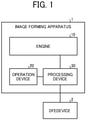
- FIG. 1 is a diagram illustrating an image forming system according to the present embodiment.
- the image forming system includes an image forming apparatus 1 and a digital front end (DFE) device 2.
- DFE digital front end
- the image forming apparatus 1 is an inkjet image forming apparatus.
- the image forming apparatus 1 includes an engine 10, an operation device 20, and a processing device 30.
- the engine 10 is a mechanical device to from an image.
- the engine 10 includes, e.g., an image forming device 12 and a reading device 133 (as illustrated in FIG. 2 ).
- the operation device 20 is a user interface to receive an operation for the image forming apparatus 1.
- the operation device 20 includes an input device, such as an operation key or a touch panel, and an output device such as a display device.
- the display device displays, e.g., an operation state or a screen related to the operation of the image forming apparatus 1.
- the processing device 30 is a controller to control the operation of the image forming apparatus 1.
- the processing device 30 is connected to the engine 10, the operation device 20, and the DFE device 2.
- the processing device 30 may be a computer device capable of executing applications on various operating systems.
- the DFE device 2 is a device that performs data processing for input to the image forming apparatus 1. For example, the DFE device 2 draws and expands print data generated in a format such as a page description language (PDL) to convert the print data into raster data. The DFE device 2 outputs the raster data to the image forming apparatus 1
- PDL page description language
- the processing device 30 causes the engine 10 to execute image formation (i.e., printing) according to the raster data generated by the DFE device 2.
- FIG. 1 illustrates the processing device 30 as a part of the image forming apparatus 1, the processing device 30 may be separate from the image forming apparatus 1.
- the processing device 30 may be implemented by an information processing device such as a personal computer (PC) and connected to the image forming apparatus 1 such that the processing device 30 can communicate with the image forming apparatus 1.
- FIG. 1 illustrates the DFE device 2 that is separate from the image forming apparatus 1, the DFE device 2 may be a part of the image forming apparatus 1 or may be provided together with the processing device 30 in a common apparatus such as an information processing device.
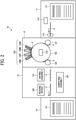
- FIG. 2 is a diagram illustrating an example of the configuration of the engine 10 of the image forming apparatus 1.
- the engine 10 includes a sheet feeding device 11, the image forming device 12, a drying device 13, and a sheet ejection device 14.
- the sheet feeding device 11 includes an input tray 111, a sheet feeder 112, and a registration roller pair 113.
- a plurality of sheets P serving as recording media is stackable on the input tray 111.
- the sheet feeder 112 separates and feeds the sheets P one at a time from the input tray 111.
- the registration roller pair 113 sends the sheet P to the image forming device 12.
- any sheet feeder may be used as the sheet feeder 112, such as a device with a roller or a device with air suction. After the leading end of the sheet P fed from the input tray 111 by the sheet feeder 112 reaches the registration roller pair 113, the registration roller pair 113 is driven at a given time to feed the sheet P to the image forming device 12. Note that the sheet feeding device 11 may have any configuration provided that the sheet feeding device 11 sends the sheet P to the image forming device 12.
- the image forming device 12 includes a receiving cylinder 121 and a sheet bearing drum 122.
- the receiving cylinder 121 conveys the fed sheet P to the sheet bearing drum 122.
- the sheet bearing drum 122 bears, on an outer circumferential surface of the sheet bearing drum 122, the sheet P conveyed by the receiving cylinder 121, to convey the sheet P to a position opposite an ink discharge device 123.
- the image forming device 12 further includes the ink discharge device 123 and a transfer cylinder 124.
- the ink discharge device 123 discharges ink droplets toward the sheet P borne on the sheet bearing drum 122.
- the transfer cylinder 124 conveys the sheet P bearing discharged ink droplets from the sheet bearing drum 122 to the drying device 13.
- the sheet P conveyed from the sheet feeding device 11 to the image forming device 12 is held by a sheet gripper provided on the surface of the receiving cylinder 121, the sheet P is conveyed along with the surface movement of the receiving cylinder 121.
- the sheet P thus conveyed by the receiving cylinder 121 is delivered to the sheet bearing drum 122 at a position opposite the sheet bearing drum 122.
- a sheet gripper is also provided on the surface of the sheet bearing drum 122 to grip the leading end of the sheet P.
- a plurality of suction holes is dispersedly formed on the surface of the sheet bearing drum 122.
- a suction device 125 generates a suction air flow toward the inside of the sheet bearing drum 122 for each of the suction holes.
- the leading end of the sheet P delivered from the receiving cylinder 121 to the sheet bearing drum 122 is held by the sheet gripper, while the sheet P is attracted to the surface of the sheet bearing drum 122 by the suction air flow. In this state, the sheet P is conveyed along with the surface movement of the sheet bearing drum 122.
- the ink discharge device 123 discharges ink droplets of four colors, namely, cyan (C), magenta (M), yellow (Y), and black (K), to form an image on the sheet P.
- the ink discharge device 123 includes heads 126C, 126M, 126Y, and 126K to discharge ink droplets of cyan, magenta, yellow, and black, respectively.
- each of the heads 126C, 126M, 126Y, and 126K has substantially the same configurations, differing from each other only in using different colors of recording liquid.
- each of the heads 126C, 126M, 126Y, and 126K includes a plurality of nozzles 126a and discharges ink droplets through the plurality of nozzles 126a.
- the heads 126 for each color are arranged side by side in a main scanning direction perpendicular to a sub-scanning direction such that the respective longitudinal ends of adjacent ones of the heads 126 overlap each other in the sub-scanning direction.
- the heads 126C, 126M, 126Y, and 126K may be simply referred to as the heads 126 when the heads 126C, 126M, 126Y, and 126K are not distinguished from each other.
- the sub-scanning direction is an example of a first direction.
- the main scanning direction is an example of a second direction.
- FIG. 3 is a diagram illustrating a configuration of one of the heads 126.
- the head 126 includes a nozzle array 126b in which a large number of nozzles 126a are arranged side by side in a line shape to form at least one nozzle array along the main scanning direction (i.e., X direction in FIG. 3 ).
- the head 126 includes the nozzle arrays 126b in a plurality of rows such as two rows along the sub-scanning direction (i.e., Y direction in FIG. 3 ), which is a direction two-dimensionally perpendicular to the main scanning direction.
- the nozzle arrays 126b in two rows are arranged side by side such that the nozzle array 126b in the front row (i.e., an upper nozzle array 126b in FIG. 3 ) and the nozzle array 126b in the rear row (i.e., a lower nozzle array 126b in FIG. 3 ) are located in a staggered manner.
- the nozzle arrays 126b are arranged side by side in the main scanning direction such that the respective longitudinal ends of adjacent ones of the nozzle arrays 126b overlap each other in the sub-scanning direction.
- the heads 126C, 126M, 126Y, and 126K illustrated in FIG. 1 are full-line inkjet heads.
- each of the nozzles 126a of the head 126 is provided with an actuator to discharge liquid.
- the drive signal drives the actuator, thus controlling the ink droplet discharge operation.
- the processing device 30 performs control to supply the drive signal to the actuator for each of the nozzles 126a of each of the heads 126. Specifically, the processing device 30 drives the actuator for each of the nozzles 126a to discharge ink droplets through the nozzle 126a to form an image on a sheet P.
- the heads 126C, 126M, 126Y, and 126K discharge ink droplets of cyan, magenta, yellow, and black, respectively, to form an image on the sheet P according to image data to be formed.
- the actuator for each of the nozzles 126a of the head 126 may be a shape deformation element actuator such as a piezo actuator, or may be another type of movable actuator.
- the actuator may be a heating actuator, such as a thermal actuator, which boils recording liquid with a heater and discharges the recording liquid from the nozzle 126a.
- the actuator may apply a voltage and discharges recording liquid by electrostatic attraction.
- the drying device 13 includes a drying assembly 131 and a conveying assembly 132.
- the drying assembly 131 dries ink droplets that has adhered to the sheet P in the image forming device 12.
- the conveying assembly 132 conveys the sheet P output from the image forming device 12 to the sheet ejection device 14.
- the conveying assembly 132 conveys the sheet P bearing the image formed by the image forming device 12 such that the sheet P passes through the drying assembly 131 to the sheet ejection device 14.
- the drying assembly 131 performs a drying process on the sheet P passing through the drying assembly 131. In the drying process, liquid components such as moisture in the ink droplets on the sheet P are evaporated and therefore the ink droplets adhere to the sheet P, while curling of the sheet P is prevented.
- the drying device 13 further includes the reading device 133.
- the reading device 133 includes an image sensor such as a charge-coupled device (CCD).
- CCD charge-coupled device
- the reading device 133 is disposed along a conveyance passage in the conveying assembly 132.
- the reading device 133 captures the sheet P conveyed along the conveyance passage, thus reading the image formed on the sheet P.
- the sheet ejection device 14 includes an output tray 141 on which a plurality of sheets P is stackable. The sheets P conveyed from the drying device 13 are sequentially stacked and held on the output tray 141. Note that the sheet ejection device 14 may have any configuration provided that the sheet ejection device 14 ejects the sheets P.
- FIG. 2 illustrates the engine 10 that includes the sheet feeding device 11, the image forming device 12, the drying device 13, and the sheet ejection device 14.
- the engine 10 may include another functional device as appropriate.
- the engine 10 may include a pre-processing device disposed between the sheet feeding device 11 and the image forming device 12 to perform pre-processing of image formation.
- the engine 10 may include a post-processing device disposed between the drying device 13 and the sheet ejection device 14 to perform post-processing of image formation.
- a device that performs a treatment liquid applying process of applying, to a sheet P, a treatment liquid that reacts with ink to prevent the ink from bleeding As an example of the post-processing device, a sheet reverse conveying device may be disposed to reverse a sheet P bearing an image formed by the image forming device 12 on one side of the sheet P and send the sheet P to the image forming device 12 again to form another image on another side of the sheet P.
- a post-processing device include, but are not limited to, a device that performs a process of binding a plurality of sheets P bearing images, a correction assembly that corrects deformation of sheets P, and a cooling assembly that cools down sheets P.
- FIG. 2 illustrates the reading device 133 disposed at a later stage of or downstream from the drying assembly 131 in a sheet conveying direction in which the sheet P is conveyed.
- the position at which the reading device 133 is disposed is not limited to the position illustrated in FIG. 2 .
- the reading device 133 may be disposed between the image forming device 12 and the drying device 13, or between the drying device 13 and the sheet ejection device 14.
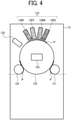
- the reading device 133 may be disposed inside the image forming device 12 as illustrated in FIG. 4 .
- FIG. 4 is a diagram illustrating another example of the configuration of the image forming device 12 described above.
- the reading device 133 is disposed at a later stage of or downstream from the ink discharge device 123 in the sheet conveying direction in which the sheet P is conveyed. Specifically, the reading device 133 is disposed near the sheet bearing drum 122 and at a later stage of or downstream from the ink discharge device 123 in the sheet conveying direction. In this case, the reading device 133 captures the sheet P bearing an image formed by the ink discharge device 123 while the sheet P is conveyed on the sheet bearing drum 122, thus reading the image formed on the sheet P.
- FIG. 5 is a diagram illustrating a hardware configuration of the processing device 30.
- the processing device 30 includes a central processing unit (CPU) 31, a memory 32, an engine interface 33, an operation device interface 34, a storage device 35, a DFE interface 36, and an image processing device 37.
- CPU central processing unit
- the CPU 31 is an example of a processor.
- the CPU 31 controls the operations of the processing device 30 and the image forming apparatus 1 as a whole.
- the memory 32 includes, e.g., a read only memory (ROM) and a random access memory (RAM).
- the memory 32 stores, e.g., setting information and various programs related to the operation of the processing device 30.
- the engine interface 33 is an interface to connect the engine 10 to the processing device 30. Under the control of the CPU 31, the engine interface 33 exchanges various kinds of data with the engine 10. For example, the engine interface 33 transmits, to the engine 10, a drive signal to control the operation of the image forming device 12. On the other hand, the engine interface 33 receives read data provided by the reading device 133 from the engine 10.
- the operation device interface 34 is an interface to connect the operation device 20 to the processing device 30. Under the control of the CPU 31, the operation device interface 34 exchanges various kinds of data with the operation device 20. For example, the operation device interface 34 receives an operation signal input via the operation device 20. On the other hand, the operation device interface 34 outputs and displays, on the operation device 20, a processing status.
- the storage device 35 is, e.g., a hard disk drive (HDD) or a solid state drive (SSD).
- the storage device 35 stores, e.g., setting information and various programs related to the operation of the processing device 30 (or the image forming apparatus 1).
- the storage device 35 also stores dither patterns described later.
- the storage device 35 stores, e.g., specification information 351, sheet information 352, and a correction parameter 353.
- FIG. 6 is a diagram illustrating an example of information stored in the storage device 35.
- the specification information 351 retains information indicating, e.g., specifications of the engine 10.
- the specification information 351 retains the printing speed and conveyance speed of the sheet P, the printing range in the main scanning direction, the printing resolutions in the main scanning direction and the sub-scanning direction, and the reading resolutions in the main scanning direction and the sub-scanning direction of the reading device 133.
- the specification information 351 retains flare characteristics indicating characteristics of a flare that occurs when the reading device 133 reads an image (e.g., a correction chart) printed on the sheet P.
- the flare indicates a phenomenon that occurs at a density boundary between different densities when the reading device 133 reads the sheet P.
- the reading device 133 reads a density value different from an actual density value, due to the influence of scattering or reflection of incident light. More specifically, the flare appears significantly at a boundary between a blank portion of the sheet P and a density patch described later or at a boundary between adjacent density patches.
- a density boundary of a density patch, or a density boundary between density patches may be referred to as an edge portion.
- FIGS. 7A and 7B illustrate the flare characteristics in the main scanning direction.
- FIG. 7A is a schematic diagram illustrating an edge portion in the main scanning direction (i.e., the X direction) on a sheet P.
- an area Pa indicates a blank portion of the sheet P; whereas an area Pb indicates an area in which a density pattern (corresponding to patches described later) is printed.
- the starting position of an arrow dX indicated by the broken line corresponds to the edge portion in the main scanning direction.
- FIG. 7B is a graph illustrating a relationship between the distance from the edge portion illustrated in FIG. 7A and the density difference (i.e., color difference) between the density detected from the area Pb and a reference density value.
- the horizontal axis represents a distance dX from the edge portion in the main scanning direction.
- the vertical axis represents a density difference ⁇ E (i.e., color difference) between the reference density value (i.e., reference color density) and the density value of the area Pb read by the reading device 133. Note that the horizontal axis indicates that the distance from the edge portion increases toward the right in FIG. 7B .
- FIGS. 8A and 8B illustrate the flare characteristics in the sub-scanning direction.
- FIG. 8A is a schematic diagram illustrating an edge portion in the sub-scanning direction (i.e., the Y direction) on a sheet P.
- an area Pa indicates a blank portion of the sheet P (or a density pattern adjacent to an area Pb); whereas the area Pb indicates an area in which a density pattern is printed.
- the starting position of an arrow dY indicated by the broken line corresponds to the edge portion in the sub-scanning direction.
- FIG. 8B is a graph illustrating a relationship between the distance from the edge portion illustrated in FIG. 8A and the density difference (i.e., color difference) between the density detected from the area Pb and a reference density value.
- the horizontal axis represents a distance dY from the edge portion in the sub-scanning direction.
- the vertical axis represents a density difference ⁇ E (i.e., color difference) between the reference density value (i.e., reference color density) and the density value of the area Pb read by the reading device 133. Note that the horizontal axis indicates that the distance from the edge portion increases toward the right in FIG. 8B .
- the density difference ⁇ E is relatively large near the edge portion and decreases as the distance from the edge portion increases.
- the influence of the flare appears significantly near the edge portion while the influence of the flare decreases as the distance from the edge portion increases.
- the specification information 351 stores, as flare characteristics, the tendencies of the flare in the main scanning direction and the sub-scanning direction when the reading device 133 reads the density image, that is, the influence of the flare relative to the distance from the edge portion.
- the specification information 351 retains, as flare characteristics, the graphs illustrated in FIGS. 7B and 8B and relational expressions from which approximate curves L1 and L2 representing the relationship between the distance from the edge portion and the density difference are derivable.
- the sheet information 352 retains information on the sheets P usable in the image forming apparatus 1.
- the sheet information 352 retains, for each type of the sheets P, characteristics such as the size (e.g., lengths in the main scanning direction and the sub-scanning direction) of the sheet P.
- the sheet information 352 may retain, for each type of the sheets P, the flare characteristics for the quality of the sheet P.
- the correction parameter 353 is an example of correction data.
- the correction parameter 353 retains a correction parameter related to correction of a density unevenness of an image formed by the image forming device 12.
- the correction parameter 353 retains a correction parameter for collecting a density unevenness of an image formed by the heads 126C, 126M, 126Y, and 126K (specifically, the nozzles 126a).
- the correction parameter may be a parameter for correcting a dither pattern or a parameter for controlling the discharge of ink droplets.
- the processing device 30 drives the heads 126C, 126M, 126Y, and 126 according to the correction parameter 353, thus causing the image forming device 12 to form an image at an appropriate density.
- the DFE interface 36 is an interface to connect the DFE device 2 to the processing device 30. Under the control of the CPU 31, the DFE interface 36 exchanges various kinds of data with the DFE device 2. For example, the DFE interface 36 transmits print data to be printed to the DFE device 2. The DFE interface 36 receives raster data generated by the DFE device 2 from the DFE device 2.
- the image processing device 37 executes various kinds of image processing. For example, under the control of the CPU 31, the image processing device 37 generates a correction chart representing a plurality of densities. A detailed description of the correction chart is deferred. In addition, under the control of the CPU 31, the image processing device 37 derives, from read data of the correction chart provided by the reading device 133, a correction parameter for correcting a density unevenness of an image formed by the image forming device 12.
- the image processing device 37 may be implemented by the CPU 31 executing a program. Alternatively, the image processing device 37 may be implemented by a processing circuit such as a graphics processing unit (GPU) independent of the CPU 31.
- a graphics processing unit GPU
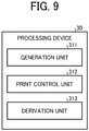
- FIG. 9 is a diagram illustrating an example of the functional configuration of the processing device 30.
- the processing device 30 includes a generation unit 311, a print control unit 312, and a derivation unit 313.
- Part or all of the generation unit 311, the print control unit 312, and the derivation unit 313 may be configured as software implemented by cooperation between the CPU 31 of the processing device 30 and various programs stored in the memory 32.
- part or all of the generation unit 311, the print control unit 312, and the derivation unit 313 may be configured as hardware implemented by, e.g., a dedicated circuit or dedicated circuits.
- the generation unit 311 and the derivation unit 313 may be implemented by programs executed by the CPU 31 and the image processing device 37.
- the generation unit 311 generates a correction chart for correcting an operation related to image formation, based on the specification information 351 and the sheet information 352. Specifically, the generation unit 311 generates a correction chart including a plurality of patches representing different densities from each other and located (or arrayed) in the sub-scanning direction.
- FIG. 10 is a diagram illustrating an example of the correction chart generated by the generation unit 311.
- the correction chart includes a plurality of patches A1 to A11 located in the sub-scanning direction (i.e., the Y direction in FIG. 10 ) and two marks M1 located at different positions from each other in the main scanning direction (i.e., the X direction in FIG. 10 ).
- the patches A1 to A11 are rectangular areas representing different densities from each other.
- the densities represented by the patches A1 to A11 are generated based on, e.g., a dither pattern.
- Dithering is a technique for artificially expressing, with fine dots, shades and colors that are physically unreproducible, as in the case of expressing more tones with a limited number of colors.
- the dither pattern is data as a basis for dot formation for such an artificial or pseudo expression.
- the patches A1 to A11 may be simply referred to as patches A when the patches A1 to A11 are not distinguished from each other.
- FIG. 10 illustrates a pattern in which the density is increased from the first patch A1 from which the printing starts to the last patch A11 at which the printing ends. That is, the patch A11 represents a highest density.
- FIG. 10 illustrates the correction chart including 11 densities (or tones), the number of tones and the density pattern are not limited to the number of tones and the density pattern illustrated in FIG. 10 .
- the length of the correction chart (i.e., the patches A) in the main scanning direction is determined according to the size of the sheet P to be used.
- the generation unit 311 reads, from the sheet information 352, the length in the main scanning direction for the type of the sheet P used for printing. Based on the length thus read, the generation unit 311 determines a length DX of the correction chart in the main scanning direction.
- the type of the sheet P used for printing may be set in advance or may be designated via the operation device 20.
- the length DX of the correction chart in the main scanning direction is not particularly limited provided that the length DX of the correction chart in the main scanning direction is equal to or less than the length of the sheet P in the main scanning direction.
- the length DX of the correction chart in the main scanning direction may be determined according to the unit of the heads 126 of the image forming device 12.
- the correction chart is printed without a so-called border so that the length DX of the correction chart in the main scanning direction is equal to the length of the sheet P in the main scanning direction.
- a blank space or margin of the sheet P is provided outside the correction chart (i.e., the patches A) in the main scanning direction so that the length DX of the correction chart in the main scanning direction is less than the length of the sheet P in the main scanning direction.
- the flare occurs at a boundary between the blank space (or margin) of the sheet P and the patches A in the main scanning direction.
- the generation unit 311 sets an invalid area, which is not used for density detection, in an edge portion of the patches A in the main scanning direction, based on the flare characteristics in the main scanning direction stored in the specification information 351. Specifically, the generation unit 311 specifies a distance dX1, at which the density difference ⁇ E is equal to or less than a threshold, from the edge portion, based on the flare characteristics in the main scanning direction. For example, the generation unit 311 specifies the distance dX1 at which the density difference ⁇ E is equal to or less than 1, based on the flare characteristics in the main scanning direction illustrated in FIGS. 7A and 7B .
- the generation unit 311 sets, as an invalid area B1 that is not used for density detection, an area from the edge portion of the patches A in the main scanning direction to a position separated from the edge portion by the distance dX1 inside the patches A.
- FIG. 10 illustrates an example in which the invalid area B1 is set at each end portion of the patches A in the main scanning direction. Then, the generation unit 311 locates marks M1 on the correction chart, based on the positions of the invalid areas B1 thus set.
- each of the marks M1 is located at a position to specify the invalid areas B1 or an area excluding the invalid areas B1 from the correction chart (such an area may be hereinafter referred to as a detection target area).
- each of the two marks M1 is located at a position, in a respective one of the opposed end portions of the plurality of patches A in the main scanning direction, according to a range of the flare that affects reading, by the reading device 133, of the plurality of patches A in the main scanning direction.
- the generation unit 311 locates the opposed end portions of the plurality of patches A in the main scanning direction outside the two marks M1 in the main scanning direction.
- Each of the marks M1 serves as an index for cutting out the correction chart from read data provided by the reading device 133 in a process described later.
- FIG. 10 illustrates an example in which the marks M1 are located outside the patches A (specifically, the patch A1) in the sub-scanning direction so as not to interfere with density detection
- the positions at which the marks M1 are located are not limited to the positions illustrated in FIG. 10 .
- FIG. 10 illustrates each of the marks M1 as a trim mark indicating a clipping position in the main scanning direction and the sub-scanning direction, that is, a corner of the detection target area
- the shape of the marks M1 is not limited to the shape illustrated in FIG. 10 .
- each of the marks M1 may indicate a clipping position in the main scanning direction.
- other marks may be located together with the marks M1.
- a mark may be located at a center position in the main scanning direction as illustrated in FIG. 10 .
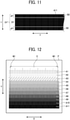
- the generation unit 311 also sets the length of the patches A in the sub-scanning direction (i.e., the Y direction) to a length including a range of the flare that affects reading, by the reading device 133, of the patches A in the sub-scanning direction.
- FIG. 11 is an enlarged view of the patch A11 as a part of the patches A illustrated in FIG. 10 .
- the generation unit 311 specifies a length dY1 of an invalid area B2 in the sub-scanning direction.
- the invalid area B2 is set for the individual patches A.
- the generation unit 311 specifies a distance dY1, at which the density difference ⁇ E is equal to or less than a threshold, from an edge portion, based on the flare characteristics in the sub-scanning direction.
- the generation unit 311 specifies the distance dY1 at which the density difference ⁇ E is equal to or less than 1, based on the flare characteristics in the sub-scanning direction illustrated in FIGS. 8A and 8B .
- the generation unit 311 determines, for each of the patches A, the length in the sub-scanning direction as DY', for example.
- the DY' is obtained by adding twice the distance dY1 to a given length DY in the sub-scanning direction.
- DY' DY + (dY1 ⁇ 2).
- the generation unit 311 sets, as the invalid area B2 that is not used for density detection, an area from the edge portion of each of the patches A in the sub-scanning direction to a position separated from the edge portion by the distance dY1 inside the corresponding patch A.
- the length DY in the sub-scanning direction is a fixed value defining a length sufficient to detect the density.
- the length DY in the sub-scanning direction may be varied according to, e.g., resolution as described later.
- the invalid areas B1 and B2 described above correspond to portions of the patches A significantly affected by the flare. Therefore, the detection accuracy is enhanced by detecting the density from a rest of the plurality of patches A excluding the invalid areas B1 and B2, that is, by detecting the density from the target area for density detection.
- the invalid area B2 in the sub-scanning direction may be set for each of the patches A, or may be set for some of the patches A. For example, since the influence of the flare increases as the density difference at the edge portions increases, the invalid area B2 may be set only for the patch A11 adjacent to the blank space or margin of the sheet P.
- the print control unit 312 causes the correction chart generated by the generation unit 311 to be printed on a sheet P. Specifically, the print control unit 312 causes the image forming device 12 to form the image of the correction chart generated by the generation unit 311 on the sheet P.
- FIG. 12 is a diagram illustrating an example of the correction chart printed on the sheet P.
- the correction chart printed on the sheet P includes the marks M1 described above.
- the reading device 133 reads the sheet P bearing the correction chart conveyed from the image forming device 12.
- the print control unit 312 may cause the image forming device 12 to directly print the correction chart generated by the generation unit 311.
- the print control unit 312 may cause the image forming device 12 to print the correction chart generated by the generation unit 311 and processed by, e.g., the DFE device 2.
- the derivation unit 313 derives a correction parameter related to the correction of the print density, based on read data provided by the reading device 133 reading the correction chart printed (or formed) on the sheet P. Specifically, the derivation unit 313 acquires the read data provided by the reading device 133 reading the correction chart printed under the control of the print control unit 312. The derivation unit 313 cuts out an area of the patches A existing inside the two marks M1 in the main scanning direction from the read data provided by the reading device 133. For example, when the sheet P in the state illustrated in FIG. 12 is read by the reading device 133, the derivation unit 313 cuts out, as a correction chart, the patches A (i.e., the patches A1 to A11) existing in a rectangular area C defined by the corners of the marks M1.
- the patches A i.e., the patches A1 to A11
- the derivation unit 313 detects the density represented by the corresponding patch A. Note that, in a case in which the invalid area B2 is set for the patch A in the sub-scanning direction, the derivation unit 313 detects the density of an area excluding the invalid area B2 from the patch A.
- the derivation unit 313 detects density from the read data of a rest of the patch A excluding the invalid area B2 of the length dY1 from each of the upper and lower ends of the patch A in the sub-scanning direction.
- the derivation unit 313 derives a correction parameter for correcting a density unevenness, based on the densities detected from the individual patches A. Then, the derivation unit 313 stores the correction parameter in the storage device 35.
- the derivation unit 313 compares a density value of each of the patches A in a correction chart as a reference prepared in advance (such a correction chart may be hereinafter referred to as a reference chart) with a detected density value or an average of detected density values, to detect the density unevenness by the unit of the heads 126 or the nozzles 126a and derives a correction parameter for correcting the density unevenness.
- the derivation unit 313 cuts out the area defined by the marks M1, thus removing the invalid areas B1 that are significantly affected by the flare. Based on the value of the length dY1 defining the invalid area B2 specified by the generation unit 311, the derivation unit 313 sets, as a target for density detection, the remaining area excluding the invalid areas B2 from the edge portions of the patch A in the sub-scanning direction.
- the derivation unit 313 detects the density from each of the patches A in a state in which the influence of the flare is reduced.
- the derivation unit 313 accurately detects the densities represented by the patches A, thus enhancing the accuracy of the correction parameter.
- the length DY of the patch A in the sub-scanning direction is fixed in the present embodiment, the length may be adjusted according to various conditions.
- the generation unit 311 adjusts the length DY of the correction chart in the sub-scanning direction, based on the ratio between a resolution as a reference in the sub-scanning direction (such a resolution may be hereinafter referred to as a reference resolution) and a reading resolution of the reading device 133 in the sub-scanning direction.
- a reference resolution is not particularly limited, and various conditions can be set.
- the reference resolution may be a resolution in the sub-scanning direction when the reference chart is read by an offline reading device different from the reading device 133.
- the reference resolution in the sub-scanning direction is 600 dots per inch (dpi); whereas a reading resolution of the reading device 133 in the sub-scanning direction stored in the specification information 351 is 300 dpi.
- the generation unit 311 adjusts the length DY of a given patch A in the sub-scanning direction to twice, based on the ratio between the reference resolution of 600 dpi and the reading resolution of 300 dpi of the reading device 133. Accordingly, the comparison with the reference chart is facilitated as the read data, in the sub-scanning direction, provided by the reading device 133 is handled in the same manner as the reference resolution.
- the generation unit 311 adjusts the length dY1 of the invalid area B2 in the sub-scanning direction by the same magnification as the magnification by which the length DY is adjusted. That is, the generation unit 311 adjusts the length DY' of the patch A including the invalid areas B2 in the sub-scanning direction, based on the reference resolution in the sub-scanning direction and the reading resolution of the reading device 133 in the sub-scanning direction.
- the generation unit 311 divides the plurality of patches A at a boundary in the sub-scanning direction into a size according to the sheet P to generate a plurality of correction charts.
- the derivation unit 313 derives a correction parameter, based on read data provided by the reading device (133) reading the plurality of correction charts.
- FIGS. 13A and 13B illustrate an example of division of the correction chart.
- the generation unit 311 divides the patches A into a plurality of groups so that each of the plurality of groups fits in one sheet P. Specifically, the generation unit 311 divides the patches A at an edge portion of one of the patches A in the sub-scanning direction, that is, at a density boundary.
- the generation unit 311 preferably divides the patches A into groups so that the divided patches A fit on a minimum number of sheets P to be used. Next, the generation unit 311 generates a correction chart for each of the divided or grouped patches A. Note that, for each of the correction charts thus generated, the generation unit 311 adds the marks M1 described above. Then, the print control unit 312 causes the image forming device 12 to print the generated correction charts on the respective sheets P.
- FIG. 13B illustrates an example of division of the patches A illustrated in FIG. 13A .
- FIG. 13B illustrates an example in which the patches A1 to A11 illustrated in FIG. 13A is divided into two at a density boundary between the patches A4 and A5 and a correction chart including the patches A1 to A4 and a correction chart including the patches A5 to A11 are printed on sheets P1 and P2, respectively.
- the derivation unit 313 performs the same processing as described above based on read data provided by the reading device 133 reading each of the sheets P1 and P2, to detect the density from the remaining area excluding the invalid areas B1 and B2 from the correction chart.
- the image forming apparatus 1 derives a correction parameter with a plurality of sheets P. That is, the image forming apparatus 1 forms a correction chart having a size according to the flare characteristics, without being affected by limitation in size of the sheet P.
- FIG. 14 a description is given of an operation of the image forming apparatus 1 (specifically, the processing device 30) related to the derivation of the correction parameter.
- FIG. 14 is a flowchart illustrating an example of the operation of the image forming apparatus 1 (specifically, the processing device 30).
- step S11 the generation unit 311 determines whether an execution of density correction is instructed.
- the generation unit 311 waits until the execution of density correction is instructed.
- the execution of density correction may be manually instructed through the operation device 20, or may be automatically instructed at the time of starting the image forming apparatus 1 or at given intervals.
- step S12 the generation unit 311 specifies the length dX1 in the main scanning direction and the length dY1 in the sub-scanning direction defining the invalid areas B1 and B2, respectively, based on the flare characteristics of the specification information 351.
- step S13 the generation unit 311 calculates the size of each of the patches A that constructs a correction chart, based on the size of a sheet P to be used, the result of operation in step S12, and the ratio between the reading resolution and the reference resolution, for example.
- step S14 the generation unit 311 determines whether the size of the correction chart in the sub-scanning direction (i.e., the length of the correction chart in the sub-scanning direction) calculated in step S13 fits in one sheet P.
- step S16 the generation unit 311 generates the correction chart including the marks M1 located at positions indicating the invalid areas B1, that is, at clipping positions of the correction chart.
- step S15 the generation unit 311 divides the patches A (as a plurality of patch areas) at a density boundary into a plurality of groups such that the size or length, in the sub-scanning direction, of a correction chart constructed of each group of the divided patches A falls within the size or length of the sheet P in the sub-scanning direction.
- step S16 the generation unit 311 generates a correction chart including the marks M1 for each group of the divided patches A.
- step S17 the print control unit 312 causes the image forming device 12 to print the correction chart generated in step S16 on the sheet P.
- the reading device 133 reads the sheet P bearing the correction chart.
- step S18 the derivation unit 313 acquires read data provided by the reading device 133.
- step S19 the derivation unit 313 cuts out the correction chart excluding the invalid areas B1 in the main scanning direction, according to the marks M1 included in the read data.
- step S20 the derivation unit 313 detects the density from the remaining area (i.e., target area) excluding the invalid areas B2, for each of the patches A included in the cut correction chart.
- step S21 the derivation unit 313 derives a correction parameter for correcting a density unevenness, based on the detection result in step S20.
- step S22 the derivation unit 313 stores the derived correction parameter as the correction parameter 353 in the storage device 35. Thus, the process ends.
- the image forming apparatus 1 (specifically, the processing device 30) generates a correction chart in which opposed end portions of the plurality of patches A in the main scanning direction are located outside the two marks M1 in the main scanning direction. Then, the image forming apparatus 1 (specifically, the processing device 30) derives correction data, based on read data provided by the reading device 133 reading the correction chart formed on a sheet P. Specifically, the read data includes read data of an area of the plurality of patches A existing inside the two marks M1 in the main scanning direction. The image forming apparatus 1 (specifically, the processing device 30) derives correction data, based on the read data of the area of the plurality of patches A existing inside the two marks M1 in the main scanning direction.
- the processing device 30 detects the density from each of the patches A while reducing the influence of the flare that occurs when the reading device 133 reads the patches A in the main scanning direction. Accordingly, the image forming apparatus 1 (specifically, the processing device 30) enhances the detection accuracy, resulting in derivation of an accurate correction parameter.
- the image forming apparatus 1 (specifically, the processing device 30) generates a correction chart including part or all of the plurality of patches A having a length in the sub-scanning direction including the range of the flare that affects reading, by the reading device 133, of the plurality of patches A in the sub-scanning direction. Then, the image forming apparatus 1 (specifically, the processing device 30) derives the correction data, based on read data provided by the reading device 133 reading the correction chart. Specifically, the read data includes read data of a remaining patches excluding the affected area in the sub-scanning direction from the correction chart. The image forming apparatus 1 (specifically, the processing device 30) derives correction data, based on the read data of the remaining patches excluding the affected area in the sub-scanning direction from the correction chart.
- the processing device 30 detects the density from each of the patches A while reducing the influence of the flare that occurs when the reading device 133 reads the patches A in the sub-scanning direction. Accordingly, the image forming apparatus 1 (specifically, the processing device 30) enhances the detection accuracy, resulting in derivation of an accurate correction parameter.
- the embodiment described above may be modified as appropriate by changing part of the configuration or functions of the image forming apparatus 1 (or the processing device 30).
- the variations described below may be individually implemented or may be combined as appropriate and implemented.
- the correction chart is generated with the marks M1 located at the positions indicating the invalid areas B1.
- the correction chart may be generated without the marks M1, as in the case of the invalid areas B2.
- the derivation unit 313 excludes the invalid area B1 from each edge portion of the patches A in the main scanning direction, based on the value of the length dX1 defining the invalid area B1 specified by the generation unit 311.
- the image forming apparatus 1 (specifically, the processing device 30) of the present variation attains substantially the same advantages attained in the embodiment described above, thus enhancing the detection accuracy, resulting in derivation of an accurate correction parameter.
- correction is performed with a correction chart while the influence of a flare is reduced.
- the present invention can be implemented in any convenient form, for example using dedicated hardware, or a mixture of dedicated hardware and software.
- the present invention may be implemented as computer software implemented by one or more networked processing apparatuses.
- the processing apparatuses include any suitably programmed apparatuses such as a general purpose computer, a personal digital assistant, a Wireless Application Protocol (WAP) or third-generation (3G)-compliant mobile telephone, and so on. Since the present invention can be implemented as software, each and every aspect of the present invention thus encompasses computer software implementable on a programmable device.
- the computer software can be provided to the programmable device using any conventional carrier medium (carrier means).
- the carrier medium includes a transient carrier medium such as an electrical, optical, microwave, acoustic or radio frequency signal carrying the computer code.
- transient medium is a Transmission Control Protocol/Internet Protocol (TCP/IP) signal carrying computer code over an IP network, such as the Internet.
- the carrier medium may also include a storage medium for storing processor readable code such as a floppy disk, a hard disk, a compact disc read-only memory (CD-ROM), a magnetic tape device, or a solid state memory device.
Landscapes
- Engineering & Computer Science (AREA)
- Multimedia (AREA)
- Signal Processing (AREA)
- General Engineering & Computer Science (AREA)
- Physics & Mathematics (AREA)
- General Physics & Mathematics (AREA)
- Theoretical Computer Science (AREA)
- Ink Jet (AREA)
- Accessory Devices And Overall Control Thereof (AREA)
- Particle Formation And Scattering Control In Inkjet Printers (AREA)
- Facsimile Image Signal Circuits (AREA)
Abstract
Description
- Embodiments of the present disclosure relate to an image forming apparatus, a method for deriving correction data, and a computer-readable carrier medium carrying computer-readable program code that causes a computer to perform the method for deriving correction data.
- A typical inkjet image forming apparatus prints a correction chart including a plurality of density patterns on a recording medium and reads the recording medium with a reading device such as a charge-coupled device (CCD), to detect and correct a density unevenness.
- For example, there is disclosed a technique of printing, on a recording medium, a correction chart generated using a dither matrix and correcting the dither matrix or the like based on the density of the correction chart read with a reading device.
- When a reading device reads a recording medium, a phenomenon called a flare may occur at a boundary of a density pattern having different densities, or at a boundary between the different densities, due to scattering or reflection of incident light. Such a flare causes erroneous reading of the densities, thus lowering the detection accuracy and the correction accuracy.
- In light of the above-described problems, it is a general object of the present invention to provide an image forming apparatus, a method for deriving correction data, and a computer-readable carrier medium carrying program code that causes a computer to perform the method for deriving correction data that allow a correction with a correction chart while reducing the influence of a flare.
- In order to achieve the above-mentioned object, there is provided an image forming apparatus according to claim 1. Advantageous embodiments are defined by the dependent claims. Advantageously, the image forming apparatus includes an image forming device, a reading device, a generation unit, and a derivation unit. The image forming device includes a head. The head includes a plurality of nozzles and is configured to discharge ink droplets through the plurality of nozzles to form an image on a recording medium conveyed in a first direction. The reading device is configured to read the image formed on the recording medium. The generation unit is configured to generate a correction chart. The correction chart includes a plurality of patches and two marks. The plurality of patches is located in the first direction and represents different densities from each other. The two marks are located at different positions from each other in a second direction perpendicular to the first direction. The generation unit is configured to locate opposed end portions of the plurality of patches in the second direction outside the two marks in the second direction. The derivation unit is configured to derive correction data, based on read data provided by the reading device reading the correction chart formed on the recording medium. The read data includes read data of an area of the plurality of patches existing inside the two marks in the second direction. The derivation unit is configured to derive the correction data, based on the read data of the area of the plurality of patches existing inside the two marks in the second direction.
- Accordingly, correction is performed with a correction chart while the influence of a flare is reduced.
- Advantageously, there is also provided a method for deriving correction data.
- Accordingly, correction is performed with a correction chart while the influence of a flare is reduced.
- A more complete appreciation of the disclosure and many of the attendant advantages and features thereof can be readily obtained and understood from the following detailed description with reference to the accompanying drawings, wherein:
-
FIG. 1 is a diagram illustrating an image forming system according to an embodiment; -
FIG. 2 is a diagram illustrating a configuration of an engine of an image forming apparatus according to an embodiment; -
FIG. 3 is a diagram illustrating a configuration of a head according to an embodiment; -
FIG. 4 is a diagram illustrating a configuration of an image forming device according to an embodiment; -
FIG. 5 is a diagram illustrating a hardware configuration of a processing device according to an embodiment; -
FIG. 6 is a diagram illustrating an example of information stored in a storage device according to an embodiment; -
FIG. 7A is a schematic diagram illustrating an edge portion in a main scanning direction on a sheet; -
FIG. 7B is a graph illustrating a relationship between the distance from the edge portion illustrated inFIG. 7A and the density difference between the density detected from an area and a reference density value; -
FIG. 8A is a schematic diagram illustrating an edge portion in a sub-scanning direction on a sheet; -
FIG. 8B is a graph illustrating a relationship between the distance from the edge portion illustrated inFIG. 8A and the density difference between the density detected from an area and a reference density value; -
FIG. 9 is a diagram illustrating a functional configuration of a processing device according to an embodiment; -
FIG. 10 is a diagram illustrating a correction chart generated by a generation unit according to an embodiment; -
FIG. 11 is an enlarged view of a part of patches illustrated inFIG. 10 ; -
FIG. 12 is a diagram illustrating a correction chart printed on a recording medium; -
FIG. 13A is a diagram illustrating a correction chart; -
FIG. 13B is a diagram illustrating an example of division of the correction chart illustrated inFIG. 13A ; and -
FIG. 14 is a flowchart illustrating an operation of a processing device of an image forming apparatus according to an embodiment. - The accompanying drawings are intended to depict embodiments of the present invention and should not be interpreted to limit the scope thereof. The accompanying drawings are not to be considered as drawn to scale unless explicitly noted. Also, identical or similar reference numerals designate identical or similar components throughout the several views.
- In describing embodiments illustrated in the drawings, specific terminology is employed for the sake of clarity. However, the disclosure of this specification is not intended to be limited to the specific terminology so selected and it is to be understood that each specific element includes all technical equivalents that have a similar function, operate in a similar manner, and achieve a similar result. As used herein, the singular forms "a," "an," and "the" are intended to include the plural forms as well, unless the context clearly indicates otherwise.
- In a later-described comparative example, embodiment, and exemplary variation, for the sake of simplicity, like reference numerals are given to identical or corresponding constituent elements such as parts and materials having the same functions, and redundant descriptions thereof are omitted unless otherwise required.
- It is to be noted that, in the following description, suffixes Y, M, C, and K denote colors of yellow, magenta, cyan, and black, respectively. To simplify the description, these suffixes are omitted unless necessary.
- Referring to the drawings, wherein like reference numerals designate identical or corresponding parts throughout the several views, embodiments of the present disclosure are described below.
- Initially with reference to
FIG. 1 , a description is given of an image forming system according to an embodiment of the present disclosure. -
FIG. 1 is a diagram illustrating an image forming system according to the present embodiment. - As illustrated in
FIG. 1 , the image forming system includes an image forming apparatus 1 and a digital front end (DFE)device 2. - The image forming apparatus 1 is an inkjet image forming apparatus. The image forming apparatus 1 includes an
engine 10, anoperation device 20, and aprocessing device 30. - The
engine 10 is a mechanical device to from an image. Theengine 10 includes, e.g., animage forming device 12 and a reading device 133 (as illustrated inFIG. 2 ). Theoperation device 20 is a user interface to receive an operation for the image forming apparatus 1. Theoperation device 20 includes an input device, such as an operation key or a touch panel, and an output device such as a display device. The display device displays, e.g., an operation state or a screen related to the operation of the image forming apparatus 1. - The
processing device 30 is a controller to control the operation of the image forming apparatus 1. Theprocessing device 30 is connected to theengine 10, theoperation device 20, and theDFE device 2. Theprocessing device 30 may be a computer device capable of executing applications on various operating systems. - The
DFE device 2 is a device that performs data processing for input to the image forming apparatus 1. For example, theDFE device 2 draws and expands print data generated in a format such as a page description language (PDL) to convert the print data into raster data. TheDFE device 2 outputs the raster data to the image forming apparatus 1 - (specifically, the processing device 30). The
processing device 30 causes theengine 10 to execute image formation (i.e., printing) according to the raster data generated by theDFE device 2. - Although
FIG. 1 illustrates theprocessing device 30 as a part of the image forming apparatus 1, theprocessing device 30 may be separate from the image forming apparatus 1. In this case, theprocessing device 30 may be implemented by an information processing device such as a personal computer (PC) and connected to the image forming apparatus 1 such that theprocessing device 30 can communicate with the image forming apparatus 1. AlthoughFIG. 1 illustrates theDFE device 2 that is separate from the image forming apparatus 1, theDFE device 2 may be a part of the image forming apparatus 1 or may be provided together with theprocessing device 30 in a common apparatus such as an information processing device. - Referring now to
FIG. 2 , a description is given of a configuration of theengine 10 described above. -
FIG. 2 is a diagram illustrating an example of the configuration of theengine 10 of the image forming apparatus 1. - As illustrated in
FIG. 2 , theengine 10 includes asheet feeding device 11, theimage forming device 12, a dryingdevice 13, and asheet ejection device 14. - The
sheet feeding device 11 includes aninput tray 111, asheet feeder 112, and aregistration roller pair 113. A plurality of sheets P serving as recording media is stackable on theinput tray 111. Thesheet feeder 112 separates and feeds the sheets P one at a time from theinput tray 111. Theregistration roller pair 113 sends the sheet P to theimage forming device 12. - Any sheet feeder may be used as the
sheet feeder 112, such as a device with a roller or a device with air suction. After the leading end of the sheet P fed from theinput tray 111 by thesheet feeder 112 reaches theregistration roller pair 113, theregistration roller pair 113 is driven at a given time to feed the sheet P to theimage forming device 12. Note that thesheet feeding device 11 may have any configuration provided that thesheet feeding device 11 sends the sheet P to theimage forming device 12. - The
image forming device 12 includes a receivingcylinder 121 and asheet bearing drum 122. The receivingcylinder 121 conveys the fed sheet P to thesheet bearing drum 122. Thesheet bearing drum 122 bears, on an outer circumferential surface of thesheet bearing drum 122, the sheet P conveyed by the receivingcylinder 121, to convey the sheet P to a position opposite anink discharge device 123. Theimage forming device 12 further includes theink discharge device 123 and atransfer cylinder 124. Theink discharge device 123 discharges ink droplets toward the sheet P borne on thesheet bearing drum 122. Thetransfer cylinder 124 conveys the sheet P bearing discharged ink droplets from thesheet bearing drum 122 to the dryingdevice 13. - As the leading end of the sheet P conveyed from the
sheet feeding device 11 to theimage forming device 12 is held by a sheet gripper provided on the surface of the receivingcylinder 121, the sheet P is conveyed along with the surface movement of the receivingcylinder 121. The sheet P thus conveyed by the receivingcylinder 121 is delivered to thesheet bearing drum 122 at a position opposite thesheet bearing drum 122. - A sheet gripper is also provided on the surface of the
sheet bearing drum 122 to grip the leading end of the sheet P. A plurality of suction holes is dispersedly formed on the surface of thesheet bearing drum 122. Asuction device 125 generates a suction air flow toward the inside of thesheet bearing drum 122 for each of the suction holes. The leading end of the sheet P delivered from the receivingcylinder 121 to thesheet bearing drum 122 is held by the sheet gripper, while the sheet P is attracted to the surface of thesheet bearing drum 122 by the suction air flow. In this state, the sheet P is conveyed along with the surface movement of thesheet bearing drum 122. - The
ink discharge device 123 discharges ink droplets of four colors, namely, cyan (C), magenta (M), yellow (Y), and black (K), to form an image on the sheet P. Theink discharge device 123 includesheads - The
heads FIG. 3 , each of theheads nozzles 126a and discharges ink droplets through the plurality ofnozzles 126a. Theheads 126 for each color are arranged side by side in a main scanning direction perpendicular to a sub-scanning direction such that the respective longitudinal ends of adjacent ones of theheads 126 overlap each other in the sub-scanning direction. Theheads heads 126 when theheads - Referring now to
FIG. 3 , a detailed description is given of theheads 126 described above. -
FIG. 3 is a diagram illustrating a configuration of one of theheads 126. - As illustrated in
FIG. 3 , thehead 126 includes anozzle array 126b in which a large number ofnozzles 126a are arranged side by side in a line shape to form at least one nozzle array along the main scanning direction (i.e., X direction inFIG. 3 ). - The
head 126 includes thenozzle arrays 126b in a plurality of rows such as two rows along the sub-scanning direction (i.e., Y direction inFIG. 3 ), which is a direction two-dimensionally perpendicular to the main scanning direction. Thenozzle arrays 126b in two rows are arranged side by side such that thenozzle array 126b in the front row (i.e., anupper nozzle array 126b inFIG. 3 ) and thenozzle array 126b in the rear row (i.e., alower nozzle array 126b inFIG. 3 ) are located in a staggered manner. That is, thenozzle arrays 126b are arranged side by side in the main scanning direction such that the respective longitudinal ends of adjacent ones of thenozzle arrays 126b overlap each other in the sub-scanning direction. In other words, theheads FIG. 1 are full-line inkjet heads. - The individual discharge operations of the
heads 126 are controlled by drive signals according to image data. Specifically, each of thenozzles 126a of thehead 126 is provided with an actuator to discharge liquid. The drive signal drives the actuator, thus controlling the ink droplet discharge operation. - The
processing device 30 performs control to supply the drive signal to the actuator for each of thenozzles 126a of each of theheads 126. Specifically, theprocessing device 30 drives the actuator for each of thenozzles 126a to discharge ink droplets through thenozzle 126a to form an image on a sheet P. With such a configuration, when the sheet P borne on thesheet bearing drum 122 passes an area opposite theink discharge device 123, theheads - Note that the actuator for each of the
nozzles 126a of thehead 126 may be a shape deformation element actuator such as a piezo actuator, or may be another type of movable actuator. The actuator may be a heating actuator, such as a thermal actuator, which boils recording liquid with a heater and discharges the recording liquid from thenozzle 126a. Alternatively, the actuator may apply a voltage and discharges recording liquid by electrostatic attraction. - Referring back to
FIG. 2 , the dryingdevice 13 includes a dryingassembly 131 and a conveyingassembly 132. The dryingassembly 131 dries ink droplets that has adhered to the sheet P in theimage forming device 12. The conveyingassembly 132 conveys the sheet P output from theimage forming device 12 to thesheet ejection device 14. - The conveying
assembly 132 conveys the sheet P bearing the image formed by theimage forming device 12 such that the sheet P passes through the dryingassembly 131 to thesheet ejection device 14. The dryingassembly 131 performs a drying process on the sheet P passing through the dryingassembly 131. In the drying process, liquid components such as moisture in the ink droplets on the sheet P are evaporated and therefore the ink droplets adhere to the sheet P, while curling of the sheet P is prevented. - The drying
device 13 further includes thereading device 133. Thereading device 133 includes an image sensor such as a charge-coupled device (CCD). Thereading device 133 is disposed along a conveyance passage in the conveyingassembly 132. Thereading device 133 captures the sheet P conveyed along the conveyance passage, thus reading the image formed on the sheet P. - The
sheet ejection device 14 includes anoutput tray 141 on which a plurality of sheets P is stackable. The sheets P conveyed from the dryingdevice 13 are sequentially stacked and held on theoutput tray 141. Note that thesheet ejection device 14 may have any configuration provided that thesheet ejection device 14 ejects the sheets P. -
FIG. 2 illustrates theengine 10 that includes thesheet feeding device 11, theimage forming device 12, the dryingdevice 13, and thesheet ejection device 14. Theengine 10 may include another functional device as appropriate. For example, theengine 10 may include a pre-processing device disposed between thesheet feeding device 11 and theimage forming device 12 to perform pre-processing of image formation. Theengine 10 may include a post-processing device disposed between the dryingdevice 13 and thesheet ejection device 14 to perform post-processing of image formation. - As an example of the pre-processing device, a device that performs a treatment liquid applying process of applying, to a sheet P, a treatment liquid that reacts with ink to prevent the ink from bleeding. As an example of the post-processing device, a sheet reverse conveying device may be disposed to reverse a sheet P bearing an image formed by the
image forming device 12 on one side of the sheet P and send the sheet P to theimage forming device 12 again to form another image on another side of the sheet P. Other examples of the post-processing device include, but are not limited to, a device that performs a process of binding a plurality of sheets P bearing images, a correction assembly that corrects deformation of sheets P, and a cooling assembly that cools down sheets P. -
FIG. 2 illustrates thereading device 133 disposed at a later stage of or downstream from the dryingassembly 131 in a sheet conveying direction in which the sheet P is conveyed. However, the position at which thereading device 133 is disposed is not limited to the position illustrated inFIG. 2 . For example, thereading device 133 may be disposed between theimage forming device 12 and the dryingdevice 13, or between the dryingdevice 13 and thesheet ejection device 14. Alternatively, thereading device 133 may be disposed inside theimage forming device 12 as illustrated inFIG. 4 . -
FIG. 4 is a diagram illustrating another example of the configuration of theimage forming device 12 described above. - In the present example, the
reading device 133 is disposed at a later stage of or downstream from theink discharge device 123 in the sheet conveying direction in which the sheet P is conveyed. Specifically, thereading device 133 is disposed near thesheet bearing drum 122 and at a later stage of or downstream from theink discharge device 123 in the sheet conveying direction. In this case, thereading device 133 captures the sheet P bearing an image formed by theink discharge device 123 while the sheet P is conveyed on thesheet bearing drum 122, thus reading the image formed on the sheet P. - Referring now to
FIG. 5 , a description is given of a configuration of theprocessing device 30 described above. -
FIG. 5 is a diagram illustrating a hardware configuration of theprocessing device 30. - As illustrated in
FIG. 5 , theprocessing device 30 includes a central processing unit (CPU) 31, amemory 32, anengine interface 33, anoperation device interface 34, astorage device 35, aDFE interface 36, and animage processing device 37. - The
CPU 31 is an example of a processor. TheCPU 31 controls the operations of theprocessing device 30 and the image forming apparatus 1 as a whole. Thememory 32 includes, e.g., a read only memory (ROM) and a random access memory (RAM). Thememory 32 stores, e.g., setting information and various programs related to the operation of theprocessing device 30. - The
engine interface 33 is an interface to connect theengine 10 to theprocessing device 30. Under the control of theCPU 31, theengine interface 33 exchanges various kinds of data with theengine 10. For example, theengine interface 33 transmits, to theengine 10, a drive signal to control the operation of theimage forming device 12. On the other hand, theengine interface 33 receives read data provided by thereading device 133 from theengine 10. - The
operation device interface 34 is an interface to connect theoperation device 20 to theprocessing device 30. Under the control of theCPU 31, theoperation device interface 34 exchanges various kinds of data with theoperation device 20. For example, theoperation device interface 34 receives an operation signal input via theoperation device 20. On the other hand, theoperation device interface 34 outputs and displays, on theoperation device 20, a processing status. - The
storage device 35 is, e.g., a hard disk drive (HDD) or a solid state drive (SSD). Thestorage device 35 stores, e.g., setting information and various programs related to the operation of the processing device 30 (or the image forming apparatus 1). Thestorage device 35 also stores dither patterns described later. - In addition, as illustrated in
FIG. 6 , thestorage device 35 stores, e.g.,specification information 351,sheet information 352, and acorrection parameter 353. -
FIG. 6 is a diagram illustrating an example of information stored in thestorage device 35. - The
specification information 351 retains information indicating, e.g., specifications of theengine 10. For example, thespecification information 351 retains the printing speed and conveyance speed of the sheet P, the printing range in the main scanning direction, the printing resolutions in the main scanning direction and the sub-scanning direction, and the reading resolutions in the main scanning direction and the sub-scanning direction of thereading device 133. - The
specification information 351 retains flare characteristics indicating characteristics of a flare that occurs when thereading device 133 reads an image (e.g., a correction chart) printed on the sheet P. Here, the flare indicates a phenomenon that occurs at a density boundary between different densities when thereading device 133 reads the sheet P. When the flare occurs, thereading device 133 reads a density value different from an actual density value, due to the influence of scattering or reflection of incident light. More specifically, the flare appears significantly at a boundary between a blank portion of the sheet P and a density patch described later or at a boundary between adjacent density patches. Hereinafter, a density boundary of a density patch, or a density boundary between density patches, may be referred to as an edge portion. - Referring now to
FIGS. 7A to 8B , a description is given of the flare characteristics of the image forming apparatus 1 (specifically, the engine 10). -
FIGS. 7A and 7B illustrate the flare characteristics in the main scanning direction. - Specifically,
FIG. 7A is a schematic diagram illustrating an edge portion in the main scanning direction (i.e., the X direction) on a sheet P. InFIG. 7A , an area Pa indicates a blank portion of the sheet P; whereas an area Pb indicates an area in which a density pattern (corresponding to patches described later) is printed. Here, the starting position of an arrow dX indicated by the broken line corresponds to the edge portion in the main scanning direction. -
FIG. 7B is a graph illustrating a relationship between the distance from the edge portion illustrated inFIG. 7A and the density difference (i.e., color difference) between the density detected from the area Pb and a reference density value. Here, the horizontal axis represents a distance dX from the edge portion in the main scanning direction. The vertical axis represents a density difference ΔE (i.e., color difference) between the reference density value (i.e., reference color density) and the density value of the area Pb read by thereading device 133. Note that the horizontal axis indicates that the distance from the edge portion increases toward the right inFIG. 7B . -
FIGS. 8A and 8B illustrate the flare characteristics in the sub-scanning direction. - Specifically,
FIG. 8A is a schematic diagram illustrating an edge portion in the sub-scanning direction (i.e., the Y direction) on a sheet P. InFIG. 8A , an area Pa indicates a blank portion of the sheet P (or a density pattern adjacent to an area Pb); whereas the area Pb indicates an area in which a density pattern is printed. Here, the starting position of an arrow dY indicated by the broken line corresponds to the edge portion in the sub-scanning direction. -
FIG. 8B is a graph illustrating a relationship between the distance from the edge portion illustrated inFIG. 8A and the density difference (i.e., color difference) between the density detected from the area Pb and a reference density value. Here, the horizontal axis represents a distance dY from the edge portion in the sub-scanning direction. The vertical axis represents a density difference ΔE (i.e., color difference) between the reference density value (i.e., reference color density) and the density value of the area Pb read by thereading device 133. Note that the horizontal axis indicates that the distance from the edge portion increases toward the right inFIG. 8B . - As illustrated in
FIGS. 7B to 8B , the density difference ΔE is relatively large near the edge portion and decreases as the distance from the edge portion increases. In other words, in each of the main scanning direction and the sub-scanning direction, the influence of the flare appears significantly near the edge portion while the influence of the flare decreases as the distance from the edge portion increases. - The
specification information 351 stores, as flare characteristics, the tendencies of the flare in the main scanning direction and the sub-scanning direction when thereading device 133 reads the density image, that is, the influence of the flare relative to the distance from the edge portion. For example, thespecification information 351 retains, as flare characteristics, the graphs illustrated inFIGS. 7B and8B and relational expressions from which approximate curves L1 and L2 representing the relationship between the distance from the edge portion and the density difference are derivable. - Referring back to
FIG. 6 , thesheet information 352 retains information on the sheets P usable in the image forming apparatus 1. For example, thesheet information 352 retains, for each type of the sheets P, characteristics such as the size (e.g., lengths in the main scanning direction and the sub-scanning direction) of the sheet P. In a case in which the flare characteristics change depending on the qualities of the sheets P (e.g., plain paper or glossy paper), thesheet information 352 may retain, for each type of the sheets P, the flare characteristics for the quality of the sheet P. - The
correction parameter 353 is an example of correction data. Thecorrection parameter 353 retains a correction parameter related to correction of a density unevenness of an image formed by theimage forming device 12. Specifically, thecorrection parameter 353 retains a correction parameter for collecting a density unevenness of an image formed by theheads nozzles 126a). For example, the correction parameter may be a parameter for correcting a dither pattern or a parameter for controlling the discharge of ink droplets. Note that theprocessing device 30 drives theheads correction parameter 353, thus causing theimage forming device 12 to form an image at an appropriate density. - Referring back to
FIG. 5 , theDFE interface 36 is an interface to connect theDFE device 2 to theprocessing device 30. Under the control of theCPU 31, theDFE interface 36 exchanges various kinds of data with theDFE device 2. For example, theDFE interface 36 transmits print data to be printed to theDFE device 2. TheDFE interface 36 receives raster data generated by theDFE device 2 from theDFE device 2. - The
image processing device 37 executes various kinds of image processing. For example, under the control of theCPU 31, theimage processing device 37 generates a correction chart representing a plurality of densities. A detailed description of the correction chart is deferred. In addition, under the control of theCPU 31, theimage processing device 37 derives, from read data of the correction chart provided by thereading device 133, a correction parameter for correcting a density unevenness of an image formed by theimage forming device 12. - The
image processing device 37 may be implemented by theCPU 31 executing a program. Alternatively, theimage processing device 37 may be implemented by a processing circuit such as a graphics processing unit (GPU) independent of theCPU 31. - Referring now to
FIG. 9 , a description is given of a functional configuration of theprocessing device 30. -
FIG. 9 is a diagram illustrating an example of the functional configuration of theprocessing device 30. - As illustrated in
FIG. 9 , theprocessing device 30 includes ageneration unit 311, aprint control unit 312, and aderivation unit 313. - Part or all of the
generation unit 311, theprint control unit 312, and thederivation unit 313 may be configured as software implemented by cooperation between theCPU 31 of theprocessing device 30 and various programs stored in thememory 32. Alternatively, part or all of thegeneration unit 311, theprint control unit 312, and thederivation unit 313 may be configured as hardware implemented by, e.g., a dedicated circuit or dedicated circuits. For example, thegeneration unit 311 and thederivation unit 313 may be implemented by programs executed by theCPU 31 and theimage processing device 37. - The
generation unit 311 generates a correction chart for correcting an operation related to image formation, based on thespecification information 351 and thesheet information 352. Specifically, thegeneration unit 311 generates a correction chart including a plurality of patches representing different densities from each other and located (or arrayed) in the sub-scanning direction. - Referring now to
FIG. 10 , a description is given of the correction chart generated by thegeneration unit 311. -
FIG. 10 is a diagram illustrating an example of the correction chart generated by thegeneration unit 311. - As illustrated in
FIG. 10 , the correction chart includes a plurality of patches A1 to A11 located in the sub-scanning direction (i.e., the Y direction inFIG. 10 ) and two marks M1 located at different positions from each other in the main scanning direction (i.e., the X direction inFIG. 10 ). - The patches A1 to A11 are rectangular areas representing different densities from each other. The densities represented by the patches A1 to A11 are generated based on, e.g., a dither pattern. Dithering is a technique for artificially expressing, with fine dots, shades and colors that are physically unreproducible, as in the case of expressing more tones with a limited number of colors. The dither pattern is data as a basis for dot formation for such an artificial or pseudo expression. Hereinafter, the patches A1 to A11 may be simply referred to as patches A when the patches A1 to A11 are not distinguished from each other.
-
FIG. 10 illustrates a pattern in which the density is increased from the first patch A1 from which the printing starts to the last patch A11 at which the printing ends. That is, the patch A11 represents a highest density. AlthoughFIG. 10 illustrates the correction chart including 11 densities (or tones), the number of tones and the density pattern are not limited to the number of tones and the density pattern illustrated inFIG. 10 . - Here, the length of the correction chart (i.e., the patches A) in the main scanning direction is determined according to the size of the sheet P to be used. Specifically, the
generation unit 311 reads, from thesheet information 352, the length in the main scanning direction for the type of the sheet P used for printing. Based on the length thus read, thegeneration unit 311 determines a length DX of the correction chart in the main scanning direction. The type of the sheet P used for printing may be set in advance or may be designated via theoperation device 20. - The length DX of the correction chart in the main scanning direction is not particularly limited provided that the length DX of the correction chart in the main scanning direction is equal to or less than the length of the sheet P in the main scanning direction. The length DX of the correction chart in the main scanning direction may be determined according to the unit of the
heads 126 of theimage forming device 12. For example, the correction chart is printed without a so-called border so that the length DX of the correction chart in the main scanning direction is equal to the length of the sheet P in the main scanning direction. By contrast, a blank space or margin of the sheet P is provided outside the correction chart (i.e., the patches A) in the main scanning direction so that the length DX of the correction chart in the main scanning direction is less than the length of the sheet P in the main scanning direction. In this case, the flare occurs at a boundary between the blank space (or margin) of the sheet P and the patches A in the main scanning direction. - Therefore, the
generation unit 311 sets an invalid area, which is not used for density detection, in an edge portion of the patches A in the main scanning direction, based on the flare characteristics in the main scanning direction stored in thespecification information 351. Specifically, thegeneration unit 311 specifies a distance dX1, at which the density difference ΔE is equal to or less than a threshold, from the edge portion, based on the flare characteristics in the main scanning direction. For example, thegeneration unit 311 specifies the distance dX1 at which the density difference ΔE is equal to or less than 1, based on the flare characteristics in the main scanning direction illustrated inFIGS. 7A and 7B . - Next, the
generation unit 311 sets, as an invalid area B1 that is not used for density detection, an area from the edge portion of the patches A in the main scanning direction to a position separated from the edge portion by the distance dX1 inside the patches A.FIG. 10 illustrates an example in which the invalid area B1 is set at each end portion of the patches A in the main scanning direction. Then, thegeneration unit 311 locates marks M1 on the correction chart, based on the positions of the invalid areas B1 thus set. - Here, each of the marks M1 is located at a position to specify the invalid areas B1 or an area excluding the invalid areas B1 from the correction chart (such an area may be hereinafter referred to as a detection target area). In other words, each of the two marks M1 is located at a position, in a respective one of the opposed end portions of the plurality of patches A in the main scanning direction, according to a range of the flare that affects reading, by the
reading device 133, of the plurality of patches A in the main scanning direction. Thus, thegeneration unit 311 locates the opposed end portions of the plurality of patches A in the main scanning direction outside the two marks M1 in the main scanning direction. Each of the marks M1 serves as an index for cutting out the correction chart from read data provided by thereading device 133 in a process described later. - Although
FIG. 10 illustrates an example in which the marks M1 are located outside the patches A (specifically, the patch A1) in the sub-scanning direction so as not to interfere with density detection, the positions at which the marks M1 are located are not limited to the positions illustrated inFIG. 10 . AlthoughFIG. 10 illustrates each of the marks M1 as a trim mark indicating a clipping position in the main scanning direction and the sub-scanning direction, that is, a corner of the detection target area, the shape of the marks M1 is not limited to the shape illustrated inFIG. 10 . For example, each of the marks M1 may indicate a clipping position in the main scanning direction. Optionally, other marks may be located together with the marks M1. For example, a mark may be located at a center position in the main scanning direction as illustrated inFIG. 10 . - The
generation unit 311 also sets the length of the patches A in the sub-scanning direction (i.e., the Y direction) to a length including a range of the flare that affects reading, by thereading device 133, of the patches A in the sub-scanning direction. - Referring now to
FIG. 11 , a description is given of a process for setting the length of the patches A in the sub-scanning direction. -
FIG. 11 is an enlarged view of the patch A11 as a part of the patches A illustrated inFIG. 10 . - First, based on the flare characteristics in the sub-scanning direction stored in the
specification information 351, thegeneration unit 311 specifies a length dY1 of an invalid area B2 in the sub-scanning direction. The invalid area B2 is set for the individual patches A. Specifically, thegeneration unit 311 specifies a distance dY1, at which the density difference ΔE is equal to or less than a threshold, from an edge portion, based on the flare characteristics in the sub-scanning direction. For example, thegeneration unit 311 specifies the distance dY1 at which the density difference ΔE is equal to or less than 1, based on the flare characteristics in the sub-scanning direction illustrated inFIGS. 8A and 8B . - Next, the
generation unit 311 determines, for each of the patches A, the length in the sub-scanning direction as DY', for example. The DY' is obtained by adding twice the distance dY1 to a given length DY in the sub-scanning direction. In short, DY' = DY + (dY1 × 2). Then, as illustrated inFIG. 11 , thegeneration unit 311 sets, as the invalid area B2 that is not used for density detection, an area from the edge portion of each of the patches A in the sub-scanning direction to a position separated from the edge portion by the distance dY1 inside the corresponding patch A. Note that the length DY in the sub-scanning direction is a fixed value defining a length sufficient to detect the density. However, the length DY in the sub-scanning direction may be varied according to, e.g., resolution as described later. - Here, the invalid areas B1 and B2 described above correspond to portions of the patches A significantly affected by the flare. Therefore, the detection accuracy is enhanced by detecting the density from a rest of the plurality of patches A excluding the invalid areas B1 and B2, that is, by detecting the density from the target area for density detection.
- Note that the invalid area B2 in the sub-scanning direction may be set for each of the patches A, or may be set for some of the patches A. For example, since the influence of the flare increases as the density difference at the edge portions increases, the invalid area B2 may be set only for the patch A11 adjacent to the blank space or margin of the sheet P.
- Referring back to
FIG. 9 , theprint control unit 312 causes the correction chart generated by thegeneration unit 311 to be printed on a sheet P. Specifically, theprint control unit 312 causes theimage forming device 12 to form the image of the correction chart generated by thegeneration unit 311 on the sheet P. -
FIG. 12 is a diagram illustrating an example of the correction chart printed on the sheet P. - As illustrated in
FIG. 12 , the correction chart printed on the sheet P includes the marks M1 described above. Thereading device 133 reads the sheet P bearing the correction chart conveyed from theimage forming device 12. - Note that the
print control unit 312 may cause theimage forming device 12 to directly print the correction chart generated by thegeneration unit 311. Alternatively, theprint control unit 312 may cause theimage forming device 12 to print the correction chart generated by thegeneration unit 311 and processed by, e.g., theDFE device 2. - The
derivation unit 313 derives a correction parameter related to the correction of the print density, based on read data provided by thereading device 133 reading the correction chart printed (or formed) on the sheet P. Specifically, thederivation unit 313 acquires the read data provided by thereading device 133 reading the correction chart printed under the control of theprint control unit 312. Thederivation unit 313 cuts out an area of the patches A existing inside the two marks M1 in the main scanning direction from the read data provided by thereading device 133. For example, when the sheet P in the state illustrated inFIG. 12 is read by thereading device 133, thederivation unit 313 cuts out, as a correction chart, the patches A (i.e., the patches A1 to A11) existing in a rectangular area C defined by the corners of the marks M1. - Next, from each of the patches A constructing the extracted correction chart, the
derivation unit 313 detects the density represented by the corresponding patch A. Note that, in a case in which the invalid area B2 is set for the patch A in the sub-scanning direction, thederivation unit 313 detects the density of an area excluding the invalid area B2 from the patch A. - For example, in a case in which the length of the patch A in the sub-scanning direction is DY' (= DY + (dY1 × 2)) as illustrated in
FIG. 11 , thederivation unit 313 detects density from the read data of a rest of the patch A excluding the invalid area B2 of the length dY1 from each of the upper and lower ends of the patch A in the sub-scanning direction. Thederivation unit 313 derives a correction parameter for correcting a density unevenness, based on the densities detected from the individual patches A. Then, thederivation unit 313 stores the correction parameter in thestorage device 35. - Note that the way of deriving the correction parameter is not particularly limited. For example, the
derivation unit 313 compares a density value of each of the patches A in a correction chart as a reference prepared in advance (such a correction chart may be hereinafter referred to as a reference chart) with a detected density value or an average of detected density values, to detect the density unevenness by the unit of theheads 126 or thenozzles 126a and derives a correction parameter for correcting the density unevenness. - Here, in the main scanning direction of the patches A printed on the sheet P, the
derivation unit 313 cuts out the area defined by the marks M1, thus removing the invalid areas B1 that are significantly affected by the flare. Based on the value of the length dY1 defining the invalid area B2 specified by thegeneration unit 311, thederivation unit 313 sets, as a target for density detection, the remaining area excluding the invalid areas B2 from the edge portions of the patch A in the sub-scanning direction. - Thus, the
derivation unit 313 detects the density from each of the patches A in a state in which the influence of the flare is reduced. Thederivation unit 313 accurately detects the densities represented by the patches A, thus enhancing the accuracy of the correction parameter. - Although the length DY of the patch A in the sub-scanning direction is fixed in the present embodiment, the length may be adjusted according to various conditions.
- For example, the
generation unit 311 adjusts the length DY of the correction chart in the sub-scanning direction, based on the ratio between a resolution as a reference in the sub-scanning direction (such a resolution may be hereinafter referred to as a reference resolution) and a reading resolution of thereading device 133 in the sub-scanning direction. Here, the reference resolution is not particularly limited, and various conditions can be set. For example, the reference resolution may be a resolution in the sub-scanning direction when the reference chart is read by an offline reading device different from thereading device 133. - As an example, the reference resolution in the sub-scanning direction is 600 dots per inch (dpi); whereas a reading resolution of the
reading device 133 in the sub-scanning direction stored in thespecification information 351 is 300 dpi. In this case, thegeneration unit 311 adjusts the length DY of a given patch A in the sub-scanning direction to twice, based on the ratio between the reference resolution of 600 dpi and the reading resolution of 300 dpi of thereading device 133. Accordingly, the comparison with the reference chart is facilitated as the read data, in the sub-scanning direction, provided by thereading device 133 is handled in the same manner as the reference resolution. - Similarly, in this case, the
generation unit 311 adjusts the length dY1 of the invalid area B2 in the sub-scanning direction by the same magnification as the magnification by which the length DY is adjusted. That is, thegeneration unit 311 adjusts the length DY' of the patch A including the invalid areas B2 in the sub-scanning direction, based on the reference resolution in the sub-scanning direction and the reading resolution of thereading device 133 in the sub-scanning direction. - Note that, adding the invalid areas B2 to one or more patches A or adjusting the length DY (or DY') in the sub-scanning direction may hamper one sheet P in accommodating all the patches A as a correction chart. In such a case, the
generation unit 311 divides the plurality of patches A at a boundary in the sub-scanning direction into a size according to the sheet P to generate a plurality of correction charts. Thederivation unit 313 derives a correction parameter, based on read data provided by the reading device (133) reading the plurality of correction charts. -
FIGS. 13A and 13B illustrate an example of division of the correction chart. - As illustrated in
FIG. 13A , in a case in which all the patches A (i.e., the patches A1-A11) do not fit in one sheet P as a correction chart, thegeneration unit 311 divides the patches A into a plurality of groups so that each of the plurality of groups fits in one sheet P. Specifically, thegeneration unit 311 divides the patches A at an edge portion of one of the patches A in the sub-scanning direction, that is, at a density boundary. - Here, the
generation unit 311 preferably divides the patches A into groups so that the divided patches A fit on a minimum number of sheets P to be used. Next, thegeneration unit 311 generates a correction chart for each of the divided or grouped patches A. Note that, for each of the correction charts thus generated, thegeneration unit 311 adds the marks M1 described above. Then, theprint control unit 312 causes theimage forming device 12 to print the generated correction charts on the respective sheets P. -
FIG. 13B illustrates an example of division of the patches A illustrated inFIG. 13A . - Specifically,
FIG. 13B illustrates an example in which the patches A1 to A11 illustrated inFIG. 13A is divided into two at a density boundary between the patches A4 and A5 and a correction chart including the patches A1 to A4 and a correction chart including the patches A5 to A11 are printed on sheets P1 and P2, respectively. - Note that the
derivation unit 313 performs the same processing as described above based on read data provided by thereading device 133 reading each of the sheets P1 and P2, to detect the density from the remaining area excluding the invalid areas B1 and B2 from the correction chart. - Thus, even in a case in which the length of the correction chart in the sub-scanning direction is equal to or greater than the length of the sheet P in the sub-scanning direction, the image forming apparatus 1 derives a correction parameter with a plurality of sheets P. That is, the image forming apparatus 1 forms a correction chart having a size according to the flare characteristics, without being affected by limitation in size of the sheet P.
- Referring now to
FIG. 14 , a description is given of an operation of the image forming apparatus 1 (specifically, the processing device 30) related to the derivation of the correction parameter. -
FIG. 14 is a flowchart illustrating an example of the operation of the image forming apparatus 1 (specifically, the processing device 30). - First, in step S11, the
generation unit 311 determines whether an execution of density correction is instructed. - When the execution of density correction is not instructed (NO in step S11), the
generation unit 311 waits until the execution of density correction is instructed. Here, the execution of density correction may be manually instructed through theoperation device 20, or may be automatically instructed at the time of starting the image forming apparatus 1 or at given intervals. - By contrast, when the execution of density correction is instructed, in other words, in response to an instruction of the execution of density correction (YES in step S11), in step S12, the
generation unit 311 specifies the length dX1 in the main scanning direction and the length dY1 in the sub-scanning direction defining the invalid areas B1 and B2, respectively, based on the flare characteristics of thespecification information 351. - Subsequently, in step S13, the
generation unit 311 calculates the size of each of the patches A that constructs a correction chart, based on the size of a sheet P to be used, the result of operation in step S12, and the ratio between the reading resolution and the reference resolution, for example. - Next, in step S14, the
generation unit 311 determines whether the size of the correction chart in the sub-scanning direction (i.e., the length of the correction chart in the sub-scanning direction) calculated in step S13 fits in one sheet P. - When the
generation unit 311 determines that the size of the correction chart in the sub-scanning direction fits in one sheet P (YES in step S14), in step S16, thegeneration unit 311 generates the correction chart including the marks M1 located at positions indicating the invalid areas B1, that is, at clipping positions of the correction chart. - On the other hand, when the
generation unit 311 determines that the size of the correction chart in the sub-scanning direction does not fit in one sheet P (NO in step S14), in step S15, thegeneration unit 311 divides the patches A (as a plurality of patch areas) at a density boundary into a plurality of groups such that the size or length, in the sub-scanning direction, of a correction chart constructed of each group of the divided patches A falls within the size or length of the sheet P in the sub-scanning direction. Next, in step S16, thegeneration unit 311 generates a correction chart including the marks M1 for each group of the divided patches A. - Subsequently, in step S17, the
print control unit 312 causes theimage forming device 12 to print the correction chart generated in step S16 on the sheet P. As the correction chart is printed on the sheet P in step S17, thereading device 133 reads the sheet P bearing the correction chart. - In step S18, the
derivation unit 313 acquires read data provided by thereading device 133. - In step S19, the
derivation unit 313 cuts out the correction chart excluding the invalid areas B1 in the main scanning direction, according to the marks M1 included in the read data. - Next, in step S20, the
derivation unit 313 detects the density from the remaining area (i.e., target area) excluding the invalid areas B2, for each of the patches A included in the cut correction chart. - Subsequently, in step S21, the
derivation unit 313 derives a correction parameter for correcting a density unevenness, based on the detection result in step S20. - Then, in step S22, the
derivation unit 313 stores the derived correction parameter as thecorrection parameter 353 in thestorage device 35. Thus, the process ends. - As described above, the image forming apparatus 1 (specifically, the processing device 30) generates a correction chart in which opposed end portions of the plurality of patches A in the main scanning direction are located outside the two marks M1 in the main scanning direction. Then, the image forming apparatus 1 (specifically, the processing device 30) derives correction data, based on read data provided by the
reading device 133 reading the correction chart formed on a sheet P. Specifically, the read data includes read data of an area of the plurality of patches A existing inside the two marks M1 in the main scanning direction. The image forming apparatus 1 (specifically, the processing device 30) derives correction data, based on the read data of the area of the plurality of patches A existing inside the two marks M1 in the main scanning direction. - That is, in the image forming apparatus 1, the
processing device 30 detects the density from each of the patches A while reducing the influence of the flare that occurs when thereading device 133 reads the patches A in the main scanning direction. Accordingly, the image forming apparatus 1 (specifically, the processing device 30) enhances the detection accuracy, resulting in derivation of an accurate correction parameter. - The image forming apparatus 1 (specifically, the processing device 30) generates a correction chart including part or all of the plurality of patches A having a length in the sub-scanning direction including the range of the flare that affects reading, by the
reading device 133, of the plurality of patches A in the sub-scanning direction. Then, the image forming apparatus 1 (specifically, the processing device 30) derives the correction data, based on read data provided by thereading device 133 reading the correction chart. Specifically, the read data includes read data of a remaining patches excluding the affected area in the sub-scanning direction from the correction chart. The image forming apparatus 1 (specifically, the processing device 30) derives correction data, based on the read data of the remaining patches excluding the affected area in the sub-scanning direction from the correction chart. - That is, in the image forming apparatus 1, the
processing device 30 detects the density from each of the patches A while reducing the influence of the flare that occurs when thereading device 133 reads the patches A in the sub-scanning direction. Accordingly, the image forming apparatus 1 (specifically, the processing device 30) enhances the detection accuracy, resulting in derivation of an accurate correction parameter. - The embodiment described above may be modified as appropriate by changing part of the configuration or functions of the image forming apparatus 1 (or the processing device 30). A description is now given of variations of the embodiment described above as other embodiments. Hereinafter, differences from the above-described embodiment will be mainly described. A detailed description of the variations redundant with the embodiment described above is herein omitted unless otherwise required. The variations described below may be individually implemented or may be combined as appropriate and implemented.
- Now, a description is given of a first variation.
- In the embodiment described above, the correction chart is generated with the marks M1 located at the positions indicating the invalid areas B1. However, the correction chart may be generated without the marks M1, as in the case of the invalid areas B2. In such a case, similarly to the process of excluding the invalid area B2, the
derivation unit 313 excludes the invalid area B1 from each edge portion of the patches A in the main scanning direction, based on the value of the length dX1 defining the invalid area B1 specified by thegeneration unit 311. - Accordingly, the image forming apparatus 1 (specifically, the processing device 30) of the present variation attains substantially the same advantages attained in the embodiment described above, thus enhancing the detection accuracy, resulting in derivation of an accurate correction parameter.
- According to the embodiments of the present disclosure, correction is performed with a correction chart while the influence of a flare is reduced.
- The above-described embodiments are illustrative and do not limit the present invention. Thus, numerous additional modifications and variations are possible in light of the above teachings. For example, elements and/or features of different illustrative embodiments may be combined with each other and/or substituted for each other within the scope of the present invention.
- Any one of the above-described operations may be performed in various other ways, for example, in an order different from the one described above.
- The present invention can be implemented in any convenient form, for example using dedicated hardware, or a mixture of dedicated hardware and software. The present invention may be implemented as computer software implemented by one or more networked processing apparatuses. The processing apparatuses include any suitably programmed apparatuses such as a general purpose computer, a personal digital assistant, a Wireless Application Protocol (WAP) or third-generation (3G)-compliant mobile telephone, and so on. Since the present invention can be implemented as software, each and every aspect of the present invention thus encompasses computer software implementable on a programmable device. The computer software can be provided to the programmable device using any conventional carrier medium (carrier means). The carrier medium includes a transient carrier medium such as an electrical, optical, microwave, acoustic or radio frequency signal carrying the computer code. An example of such a transient medium is a Transmission Control Protocol/Internet Protocol (TCP/IP) signal carrying computer code over an IP network, such as the Internet. The carrier medium may also include a storage medium for storing processor readable code such as a floppy disk, a hard disk, a compact disc read-only memory (CD-ROM), a magnetic tape device, or a solid state memory device.
Claims (7)
- An image forming apparatus (1) comprising:an image forming device (12) including a head, the head including a plurality of nozzles and being configured to discharge ink droplets through the plurality of nozzles to form an image on a recording medium conveyed in a first direction;a reading device (133) configured to read the image formed on the recording medium;a generation unit (311) configured to generate a correction chart, the correction chart including:a plurality of patches located in the first direction and representing different densities from each other; andtwo marks located at different positions from each other in a second direction perpendicular to the first direction,the generation unit (311) being configured to locate opposed end portions of the plurality of patches in the second direction outside the two marks in the second direction; anda derivation unit (313) configured to derive correction data, based on read data provided by the reading device (133) reading the correction chart formed on the recording medium, the read data including read data of an area of the plurality of patches existing inside the two marks in the second direction,the derivation unit (313) being configured to derive the correction data, based on the read data of the area of the plurality of patches existing inside the two marks in the second direction.
- The image forming apparatus (1) according to claim 1,
wherein the generation unit (311) is configured to locate each of the two marks at a position, in a respective one of the opposed end portions of the plurality of patches in the second direction, according to a range of a flare that affects reading, by the reading device (133), of the plurality of patches in the second direction. - The image forming apparatus (1) according to claim 1 or 2,
wherein the generation unit (311) is configured to set a length of part or all of the plurality of patches in the first direction to a length including a range of a flare that affects reading, by the reading device (133), of the plurality of patches in the first direction,
wherein the read data provided by the reading device (133) further includes read data of a rest of the plurality of patches excluding the range in the first direction, and
wherein the derivation unit (313) is configured to derive the correction data, based on the read data of the rest of the plurality of patches excluding the range in the first direction. - The image forming apparatus (1) according to claim 3,
wherein the generation unit (311) is configured to set a length, in the first direction, of one of the plurality of patches representing a highest density to a length including the range. - The image forming apparatus (1) according to any one of claims 1 to 4, wherein the generation unit (311) is configured, in a case in which the correction chart does not fit in the recording medium, to divide the plurality of patches at a boundary in the first direction into a size according to the recording medium to generate a plurality of correction charts, and
wherein the derivation unit (313) is configured to derive the correction data, based on read data provided by the reading device (133) reading the plurality of correction charts. - A method for deriving correction data, the method comprising:generating (S16) a correction chart, the correction chart including:a plurality of patches located in a first direction in which a recording medium is conveyed,the plurality of patches representing different densities from each other; andtwo marks located at different positions from each other in a second direction perpendicular to the first direction,the generating (S16) including locating opposed end portions of the plurality of patches in the second direction outside the two marks in the second direction; andderiving (S21) correction data, based on read data provided by a reading device reading the correction chart formed on the recording medium, the read data including read data of an area of the plurality of patches existing inside the two marks in the second direction,the deriving (S21) including deriving the correction data, based on the read data of the area of the plurality of patches existing inside the two marks in the second direction.
- A computer-readable carrier medium carrying computer-readable program code that causes a computer to perform the method for deriving correction data according to claim 6.
Applications Claiming Priority (1)
| Application Number | Priority Date | Filing Date | Title |
|---|---|---|---|
| JP2020121390A JP7608743B2 (en) | 2020-07-15 | 2020-07-15 | Image forming apparatus, correction data derivation method and program |
Publications (2)
| Publication Number | Publication Date |
|---|---|
| EP3940593A1 true EP3940593A1 (en) | 2022-01-19 |
| EP3940593B1 EP3940593B1 (en) | 2024-01-10 |
Family
ID=76532119
Family Applications (1)
| Application Number | Title | Priority Date | Filing Date |
|---|---|---|---|
| EP21180468.7A Active EP3940593B1 (en) | 2020-07-15 | 2021-06-18 | Image forming apparatus, method for deriving correction data, and computer-readable carrier medium |
Country Status (4)
| Country | Link |
|---|---|
| US (1) | US11820157B2 (en) |
| EP (1) | EP3940593B1 (en) |
| JP (1) | JP7608743B2 (en) |
| CN (1) | CN113942305B (en) |
Citations (4)
| Publication number | Priority date | Publication date | Assignee | Title |
|---|---|---|---|---|
| US5185673A (en) * | 1991-06-12 | 1993-02-09 | Hewlett-Packard Company | Automated image calibration |
| US20030053154A1 (en) * | 2001-09-19 | 2003-03-20 | Yoshikatsu Kamisuwa | Image checking system |
| US20120223989A1 (en) * | 2011-03-02 | 2012-09-06 | Ricoh Company, Limited | Image forming apparatus, image correcting method, and computer-readable storage medium |
| US20170064142A1 (en) * | 2015-09-02 | 2017-03-02 | Seiko Epson Corporation | Method for correcting density irregularity, printing apparatus, and imaging module |
Family Cites Families (15)
| Publication number | Priority date | Publication date | Assignee | Title |
|---|---|---|---|---|
| US7095531B2 (en) * | 2003-11-06 | 2006-08-22 | Xerox Corporation | Systems and methods for compensating for streaks in images |
| JP4828241B2 (en) | 2006-01-25 | 2011-11-30 | 大日本スクリーン製造株式会社 | Printing apparatus, dither matrix generation method, and dither matrix |
| JP2008134280A (en) | 2006-11-27 | 2008-06-12 | Ricoh Co Ltd | Image forming apparatus and image forming method |
| JP2010036452A (en) | 2008-08-05 | 2010-02-18 | Fuji Xerox Co Ltd | Image forming apparatus and density deviation correcting program |
| JP5729101B2 (en) | 2011-04-11 | 2015-06-03 | 株式会社リコー | Image processing apparatus, image forming apparatus, image processing method, image processing program, and recording medium |
| JP2013136170A (en) | 2011-12-28 | 2013-07-11 | Dainippon Screen Mfg Co Ltd | Inkjet printer and chart |
| JP6119280B2 (en) | 2013-02-08 | 2017-04-26 | 株式会社リコー | Dither matrix generation method, image processing method, image processing apparatus, and program |
| JP5855607B2 (en) * | 2013-06-28 | 2016-02-09 | 富士フイルム株式会社 | Image recording method, apparatus and program |
| JP2016086223A (en) | 2014-10-23 | 2016-05-19 | 株式会社リコー | Image processing apparatus, image processing method, image processing program, and image forming apparatus |
| JP6451301B2 (en) | 2014-12-22 | 2019-01-16 | コニカミノルタ株式会社 | Image forming apparatus |
| JP6142882B2 (en) | 2015-01-28 | 2017-06-07 | コニカミノルタ株式会社 | Image forming apparatus |
| US10477068B2 (en) | 2016-03-18 | 2019-11-12 | Ricoh Company, Ltd. | Image processing apparatus for primary color and spot halftoning |
| JP6878843B2 (en) | 2016-11-11 | 2021-06-02 | 株式会社リコー | Inkjet device |
| US10460217B2 (en) | 2017-03-16 | 2019-10-29 | Ricoh Company, Ltd. | Information processing device, information processing method, and computer-readable recording medium |
| JP6954008B2 (en) | 2017-11-01 | 2021-10-27 | 株式会社リコー | Image inspection equipment, image inspection system and image inspection method |
-
2020
- 2020-07-15 JP JP2020121390A patent/JP7608743B2/en active Active
-
2021
- 2021-06-18 EP EP21180468.7A patent/EP3940593B1/en active Active
- 2021-06-22 US US17/354,950 patent/US11820157B2/en active Active
- 2021-07-12 CN CN202110782628.1A patent/CN113942305B/en active Active
Patent Citations (4)
| Publication number | Priority date | Publication date | Assignee | Title |
|---|---|---|---|---|
| US5185673A (en) * | 1991-06-12 | 1993-02-09 | Hewlett-Packard Company | Automated image calibration |
| US20030053154A1 (en) * | 2001-09-19 | 2003-03-20 | Yoshikatsu Kamisuwa | Image checking system |
| US20120223989A1 (en) * | 2011-03-02 | 2012-09-06 | Ricoh Company, Limited | Image forming apparatus, image correcting method, and computer-readable storage medium |
| US20170064142A1 (en) * | 2015-09-02 | 2017-03-02 | Seiko Epson Corporation | Method for correcting density irregularity, printing apparatus, and imaging module |
Also Published As
| Publication number | Publication date |
|---|---|
| CN113942305A (en) | 2022-01-18 |
| JP7608743B2 (en) | 2025-01-07 |
| JP2022018339A (en) | 2022-01-27 |
| US11820157B2 (en) | 2023-11-21 |
| US20220016902A1 (en) | 2022-01-20 |
| CN113942305B (en) | 2023-05-30 |
| EP3940593B1 (en) | 2024-01-10 |
Similar Documents
| Publication | Publication Date | Title |
|---|---|---|
| US9152890B2 (en) | Image recording method and apparatus, and recording medium | |
| US9242457B2 (en) | Control apparatus, control method, and program | |
| JP6049268B2 (en) | Inkjet recording device | |
| US7390073B2 (en) | Method and apparatus for performing alignment for printing with a printhead | |
| US8646862B2 (en) | System and method for detection and compensation of inoperable inkjets in an inkjet printing apparatus | |
| US8967751B2 (en) | Image processing apparatus and image processing method | |
| US10336066B2 (en) | Printer and control method of a printer | |
| JP2024046494A (en) | Image formation device | |
| US20180297359A1 (en) | Printer and control method | |
| JP6171289B2 (en) | Image processing method, image processing apparatus, and program | |
| JP2014100854A (en) | Apparatus and method for image formation and method of calculating correction value | |
| US20110193905A1 (en) | Printing device | |
| JP4513346B2 (en) | Printing apparatus, printing method, and printing system | |
| EP3940593B1 (en) | Image forming apparatus, method for deriving correction data, and computer-readable carrier medium | |
| JP2014104679A (en) | Ink jet recording device and control method of ink jet recording device | |
| EP4420882A1 (en) | Automatic tuning compensation mechanism | |
| US20180264854A1 (en) | Image forming apparatus, control method thereof, and examination method | |
| EP3102417B1 (en) | Ink jet printing method and printer | |
| JP5816041B2 (en) | Color inkjet printer | |
| US7880928B2 (en) | Color image process controls methods and systems | |
| EP4716205A2 (en) | Image formation control method and image forming apparatus | |
| US20250353294A1 (en) | Image forming apparatus | |
| JP7451038B2 (en) | Printing system and printing method | |
| JP7434852B2 (en) | Method of producing printing device and printing device | |
| US11954821B1 (en) | Altering pixels to scale images |
Legal Events
| Date | Code | Title | Description |
|---|---|---|---|
| PUAI | Public reference made under article 153(3) epc to a published international application that has entered the european phase |
Free format text: ORIGINAL CODE: 0009012 |
|
| STAA | Information on the status of an ep patent application or granted ep patent |
Free format text: STATUS: REQUEST FOR EXAMINATION WAS MADE |
|
| 17P | Request for examination filed |
Effective date: 20210618 |
|
| AK | Designated contracting states |
Kind code of ref document: A1 Designated state(s): AL AT BE BG CH CY CZ DE DK EE ES FI FR GB GR HR HU IE IS IT LI LT LU LV MC MK MT NL NO PL PT RO RS SE SI SK SM TR |
|
| GRAP | Despatch of communication of intention to grant a patent |
Free format text: ORIGINAL CODE: EPIDOSNIGR1 |
|
| STAA | Information on the status of an ep patent application or granted ep patent |
Free format text: STATUS: GRANT OF PATENT IS INTENDED |
|
| INTG | Intention to grant announced |
Effective date: 20230823 |
|
| P01 | Opt-out of the competence of the unified patent court (upc) registered |
Effective date: 20230926 |
|
| GRAS | Grant fee paid |
Free format text: ORIGINAL CODE: EPIDOSNIGR3 |
|
| GRAA | (expected) grant |
Free format text: ORIGINAL CODE: 0009210 |
|
| STAA | Information on the status of an ep patent application or granted ep patent |
Free format text: STATUS: THE PATENT HAS BEEN GRANTED |
|
| AK | Designated contracting states |
Kind code of ref document: B1 Designated state(s): AL AT BE BG CH CY CZ DE DK EE ES FI FR GB GR HR HU IE IS IT LI LT LU LV MC MK MT NL NO PL PT RO RS SE SI SK SM TR |
|
| REG | Reference to a national code |
Ref country code: GB Ref legal event code: FG4D |
|
| REG | Reference to a national code |
Ref country code: CH Ref legal event code: EP |
|
| REG | Reference to a national code |
Ref country code: DE Ref legal event code: R096 Ref document number: 602021008456 Country of ref document: DE |
|
| REG | Reference to a national code |
Ref country code: IE Ref legal event code: FG4D |
|
| REG | Reference to a national code |
Ref country code: LT Ref legal event code: MG9D |
|
| REG | Reference to a national code |
Ref country code: NL Ref legal event code: MP Effective date: 20240110 |
|
| REG | Reference to a national code |
Ref country code: AT Ref legal event code: MK05 Ref document number: 1649475 Country of ref document: AT Kind code of ref document: T Effective date: 20240110 |
|
| PG25 | Lapsed in a contracting state [announced via postgrant information from national office to epo] |
Ref country code: NL Free format text: LAPSE BECAUSE OF FAILURE TO SUBMIT A TRANSLATION OF THE DESCRIPTION OR TO PAY THE FEE WITHIN THE PRESCRIBED TIME-LIMIT Effective date: 20240110 |
|
| PG25 | Lapsed in a contracting state [announced via postgrant information from national office to epo] |
Ref country code: NL Free format text: LAPSE BECAUSE OF FAILURE TO SUBMIT A TRANSLATION OF THE DESCRIPTION OR TO PAY THE FEE WITHIN THE PRESCRIBED TIME-LIMIT Effective date: 20240110 |
|
| PG25 | Lapsed in a contracting state [announced via postgrant information from national office to epo] |
Ref country code: IS Free format text: LAPSE BECAUSE OF FAILURE TO SUBMIT A TRANSLATION OF THE DESCRIPTION OR TO PAY THE FEE WITHIN THE PRESCRIBED TIME-LIMIT Effective date: 20240510 |
|
| PG25 | Lapsed in a contracting state [announced via postgrant information from national office to epo] |
Ref country code: LT Free format text: LAPSE BECAUSE OF FAILURE TO SUBMIT A TRANSLATION OF THE DESCRIPTION OR TO PAY THE FEE WITHIN THE PRESCRIBED TIME-LIMIT Effective date: 20240110 |
|
| PG25 | Lapsed in a contracting state [announced via postgrant information from national office to epo] |
Ref country code: GR Free format text: LAPSE BECAUSE OF FAILURE TO SUBMIT A TRANSLATION OF THE DESCRIPTION OR TO PAY THE FEE WITHIN THE PRESCRIBED TIME-LIMIT Effective date: 20240411 |
|
| PG25 | Lapsed in a contracting state [announced via postgrant information from national office to epo] |
Ref country code: RS Free format text: LAPSE BECAUSE OF FAILURE TO SUBMIT A TRANSLATION OF THE DESCRIPTION OR TO PAY THE FEE WITHIN THE PRESCRIBED TIME-LIMIT Effective date: 20240410 Ref country code: HR Free format text: LAPSE BECAUSE OF FAILURE TO SUBMIT A TRANSLATION OF THE DESCRIPTION OR TO PAY THE FEE WITHIN THE PRESCRIBED TIME-LIMIT Effective date: 20240110 |
|
| PG25 | Lapsed in a contracting state [announced via postgrant information from national office to epo] |
Ref country code: ES Free format text: LAPSE BECAUSE OF FAILURE TO SUBMIT A TRANSLATION OF THE DESCRIPTION OR TO PAY THE FEE WITHIN THE PRESCRIBED TIME-LIMIT Effective date: 20240110 |
|
| PG25 | Lapsed in a contracting state [announced via postgrant information from national office to epo] |
Ref country code: AT Free format text: LAPSE BECAUSE OF FAILURE TO SUBMIT A TRANSLATION OF THE DESCRIPTION OR TO PAY THE FEE WITHIN THE PRESCRIBED TIME-LIMIT Effective date: 20240110 |
|
| PG25 | Lapsed in a contracting state [announced via postgrant information from national office to epo] |
Ref country code: RS Free format text: LAPSE BECAUSE OF FAILURE TO SUBMIT A TRANSLATION OF THE DESCRIPTION OR TO PAY THE FEE WITHIN THE PRESCRIBED TIME-LIMIT Effective date: 20240410 Ref country code: NO Free format text: LAPSE BECAUSE OF FAILURE TO SUBMIT A TRANSLATION OF THE DESCRIPTION OR TO PAY THE FEE WITHIN THE PRESCRIBED TIME-LIMIT Effective date: 20240410 Ref country code: LT Free format text: LAPSE BECAUSE OF FAILURE TO SUBMIT A TRANSLATION OF THE DESCRIPTION OR TO PAY THE FEE WITHIN THE PRESCRIBED TIME-LIMIT Effective date: 20240110 Ref country code: IS Free format text: LAPSE BECAUSE OF FAILURE TO SUBMIT A TRANSLATION OF THE DESCRIPTION OR TO PAY THE FEE WITHIN THE PRESCRIBED TIME-LIMIT Effective date: 20240510 Ref country code: HR Free format text: LAPSE BECAUSE OF FAILURE TO SUBMIT A TRANSLATION OF THE DESCRIPTION OR TO PAY THE FEE WITHIN THE PRESCRIBED TIME-LIMIT Effective date: 20240110 Ref country code: GR Free format text: LAPSE BECAUSE OF FAILURE TO SUBMIT A TRANSLATION OF THE DESCRIPTION OR TO PAY THE FEE WITHIN THE PRESCRIBED TIME-LIMIT Effective date: 20240411 Ref country code: ES Free format text: LAPSE BECAUSE OF FAILURE TO SUBMIT A TRANSLATION OF THE DESCRIPTION OR TO PAY THE FEE WITHIN THE PRESCRIBED TIME-LIMIT Effective date: 20240110 Ref country code: BG Free format text: LAPSE BECAUSE OF FAILURE TO SUBMIT A TRANSLATION OF THE DESCRIPTION OR TO PAY THE FEE WITHIN THE PRESCRIBED TIME-LIMIT Effective date: 20240110 Ref country code: AT Free format text: LAPSE BECAUSE OF FAILURE TO SUBMIT A TRANSLATION OF THE DESCRIPTION OR TO PAY THE FEE WITHIN THE PRESCRIBED TIME-LIMIT Effective date: 20240110 |
|
| PG25 | Lapsed in a contracting state [announced via postgrant information from national office to epo] |
Ref country code: PL Free format text: LAPSE BECAUSE OF FAILURE TO SUBMIT A TRANSLATION OF THE DESCRIPTION OR TO PAY THE FEE WITHIN THE PRESCRIBED TIME-LIMIT Effective date: 20240110 Ref country code: PT Free format text: LAPSE BECAUSE OF FAILURE TO SUBMIT A TRANSLATION OF THE DESCRIPTION OR TO PAY THE FEE WITHIN THE PRESCRIBED TIME-LIMIT Effective date: 20240510 |
|
| PG25 | Lapsed in a contracting state [announced via postgrant information from national office to epo] |
Ref country code: SE Free format text: LAPSE BECAUSE OF FAILURE TO SUBMIT A TRANSLATION OF THE DESCRIPTION OR TO PAY THE FEE WITHIN THE PRESCRIBED TIME-LIMIT Effective date: 20240110 Ref country code: PT Free format text: LAPSE BECAUSE OF FAILURE TO SUBMIT A TRANSLATION OF THE DESCRIPTION OR TO PAY THE FEE WITHIN THE PRESCRIBED TIME-LIMIT Effective date: 20240510 Ref country code: PL Free format text: LAPSE BECAUSE OF FAILURE TO SUBMIT A TRANSLATION OF THE DESCRIPTION OR TO PAY THE FEE WITHIN THE PRESCRIBED TIME-LIMIT Effective date: 20240110 Ref country code: LV Free format text: LAPSE BECAUSE OF FAILURE TO SUBMIT A TRANSLATION OF THE DESCRIPTION OR TO PAY THE FEE WITHIN THE PRESCRIBED TIME-LIMIT Effective date: 20240110 |
|
| PG25 | Lapsed in a contracting state [announced via postgrant information from national office to epo] |
Ref country code: DK Free format text: LAPSE BECAUSE OF FAILURE TO SUBMIT A TRANSLATION OF THE DESCRIPTION OR TO PAY THE FEE WITHIN THE PRESCRIBED TIME-LIMIT Effective date: 20240110 |
|
| REG | Reference to a national code |
Ref country code: DE Ref legal event code: R097 Ref document number: 602021008456 Country of ref document: DE |
|
| PG25 | Lapsed in a contracting state [announced via postgrant information from national office to epo] |
Ref country code: SM Free format text: LAPSE BECAUSE OF FAILURE TO SUBMIT A TRANSLATION OF THE DESCRIPTION OR TO PAY THE FEE WITHIN THE PRESCRIBED TIME-LIMIT Effective date: 20240110 |
|
| PG25 | Lapsed in a contracting state [announced via postgrant information from national office to epo] |
Ref country code: EE Free format text: LAPSE BECAUSE OF FAILURE TO SUBMIT A TRANSLATION OF THE DESCRIPTION OR TO PAY THE FEE WITHIN THE PRESCRIBED TIME-LIMIT Effective date: 20240110 Ref country code: CZ Free format text: LAPSE BECAUSE OF FAILURE TO SUBMIT A TRANSLATION OF THE DESCRIPTION OR TO PAY THE FEE WITHIN THE PRESCRIBED TIME-LIMIT Effective date: 20240110 |
|
| PG25 | Lapsed in a contracting state [announced via postgrant information from national office to epo] |
Ref country code: SK Free format text: LAPSE BECAUSE OF FAILURE TO SUBMIT A TRANSLATION OF THE DESCRIPTION OR TO PAY THE FEE WITHIN THE PRESCRIBED TIME-LIMIT Effective date: 20240110 |
|
| PG25 | Lapsed in a contracting state [announced via postgrant information from national office to epo] |
Ref country code: SM Free format text: LAPSE BECAUSE OF FAILURE TO SUBMIT A TRANSLATION OF THE DESCRIPTION OR TO PAY THE FEE WITHIN THE PRESCRIBED TIME-LIMIT Effective date: 20240110 Ref country code: SK Free format text: LAPSE BECAUSE OF FAILURE TO SUBMIT A TRANSLATION OF THE DESCRIPTION OR TO PAY THE FEE WITHIN THE PRESCRIBED TIME-LIMIT Effective date: 20240110 Ref country code: RO Free format text: LAPSE BECAUSE OF FAILURE TO SUBMIT A TRANSLATION OF THE DESCRIPTION OR TO PAY THE FEE WITHIN THE PRESCRIBED TIME-LIMIT Effective date: 20240110 Ref country code: EE Free format text: LAPSE BECAUSE OF FAILURE TO SUBMIT A TRANSLATION OF THE DESCRIPTION OR TO PAY THE FEE WITHIN THE PRESCRIBED TIME-LIMIT Effective date: 20240110 Ref country code: DK Free format text: LAPSE BECAUSE OF FAILURE TO SUBMIT A TRANSLATION OF THE DESCRIPTION OR TO PAY THE FEE WITHIN THE PRESCRIBED TIME-LIMIT Effective date: 20240110 Ref country code: CZ Free format text: LAPSE BECAUSE OF FAILURE TO SUBMIT A TRANSLATION OF THE DESCRIPTION OR TO PAY THE FEE WITHIN THE PRESCRIBED TIME-LIMIT Effective date: 20240110 |
|
| PLBE | No opposition filed within time limit |
Free format text: ORIGINAL CODE: 0009261 |
|
| STAA | Information on the status of an ep patent application or granted ep patent |
Free format text: STATUS: NO OPPOSITION FILED WITHIN TIME LIMIT |
|
| PG25 | Lapsed in a contracting state [announced via postgrant information from national office to epo] |
Ref country code: IT Free format text: LAPSE BECAUSE OF FAILURE TO SUBMIT A TRANSLATION OF THE DESCRIPTION OR TO PAY THE FEE WITHIN THE PRESCRIBED TIME-LIMIT Effective date: 20240110 |
|
| 26N | No opposition filed |
Effective date: 20241011 |
|
| PG25 | Lapsed in a contracting state [announced via postgrant information from national office to epo] |
Ref country code: IT Free format text: LAPSE BECAUSE OF FAILURE TO SUBMIT A TRANSLATION OF THE DESCRIPTION OR TO PAY THE FEE WITHIN THE PRESCRIBED TIME-LIMIT Effective date: 20240110 |
|
| PG25 | Lapsed in a contracting state [announced via postgrant information from national office to epo] |
Ref country code: MC Free format text: LAPSE BECAUSE OF FAILURE TO SUBMIT A TRANSLATION OF THE DESCRIPTION OR TO PAY THE FEE WITHIN THE PRESCRIBED TIME-LIMIT Effective date: 20240110 |
|
| REG | Reference to a national code |
Ref country code: CH Ref legal event code: PL |
|
| PG25 | Lapsed in a contracting state [announced via postgrant information from national office to epo] |
Ref country code: LU Free format text: LAPSE BECAUSE OF NON-PAYMENT OF DUE FEES Effective date: 20240618 |
|
| PG25 | Lapsed in a contracting state [announced via postgrant information from national office to epo] |
Ref country code: IE Free format text: LAPSE BECAUSE OF NON-PAYMENT OF DUE FEES Effective date: 20240618 |
|
| PG25 | Lapsed in a contracting state [announced via postgrant information from national office to epo] |
Ref country code: SI Free format text: LAPSE BECAUSE OF FAILURE TO SUBMIT A TRANSLATION OF THE DESCRIPTION OR TO PAY THE FEE WITHIN THE PRESCRIBED TIME-LIMIT Effective date: 20240110 Ref country code: BE Free format text: LAPSE BECAUSE OF NON-PAYMENT OF DUE FEES Effective date: 20240630 Ref country code: CH Free format text: LAPSE BECAUSE OF NON-PAYMENT OF DUE FEES Effective date: 20240630 |
|
| REG | Reference to a national code |
Ref country code: BE Ref legal event code: MM Effective date: 20240630 |
|
| PGFP | Annual fee paid to national office [announced via postgrant information from national office to epo] |
Ref country code: DE Payment date: 20250618 Year of fee payment: 5 |
|
| PGFP | Annual fee paid to national office [announced via postgrant information from national office to epo] |
Ref country code: GB Payment date: 20250618 Year of fee payment: 5 |
|
| PGFP | Annual fee paid to national office [announced via postgrant information from national office to epo] |
Ref country code: FR Payment date: 20250627 Year of fee payment: 5 |
|
| PG25 | Lapsed in a contracting state [announced via postgrant information from national office to epo] |
Ref country code: FI Free format text: LAPSE BECAUSE OF FAILURE TO SUBMIT A TRANSLATION OF THE DESCRIPTION OR TO PAY THE FEE WITHIN THE PRESCRIBED TIME-LIMIT Effective date: 20240110 |
|
| PG25 | Lapsed in a contracting state [announced via postgrant information from national office to epo] |
Ref country code: CY Free format text: LAPSE BECAUSE OF FAILURE TO SUBMIT A TRANSLATION OF THE DESCRIPTION OR TO PAY THE FEE WITHIN THE PRESCRIBED TIME-LIMIT; INVALID AB INITIO Effective date: 20210618 |
|
| PG25 | Lapsed in a contracting state [announced via postgrant information from national office to epo] |
Ref country code: HU Free format text: LAPSE BECAUSE OF FAILURE TO SUBMIT A TRANSLATION OF THE DESCRIPTION OR TO PAY THE FEE WITHIN THE PRESCRIBED TIME-LIMIT; INVALID AB INITIO Effective date: 20210618 |