EP3940422B1 - Information processing device and mobile robot - Google Patents
Information processing device and mobile robot Download PDFInfo
- Publication number
- EP3940422B1 EP3940422B1 EP19919202.2A EP19919202A EP3940422B1 EP 3940422 B1 EP3940422 B1 EP 3940422B1 EP 19919202 A EP19919202 A EP 19919202A EP 3940422 B1 EP3940422 B1 EP 3940422B1
- Authority
- EP
- European Patent Office
- Prior art keywords
- self
- map
- reliability
- current
- information
- Prior art date
- Legal status (The legal status is an assumption and is not a legal conclusion. Google has not performed a legal analysis and makes no representation as to the accuracy of the status listed.)
- Active
Links
Images


Classifications
-
- G—PHYSICS
- G01—MEASURING; TESTING
- G01C—MEASURING DISTANCES, LEVELS OR BEARINGS; SURVEYING; NAVIGATION; GYROSCOPIC INSTRUMENTS; PHOTOGRAMMETRY OR VIDEOGRAMMETRY
- G01C21/00—Navigation; Navigational instruments not provided for in groups G01C1/00 - G01C19/00
- G01C21/26—Navigation; Navigational instruments not provided for in groups G01C1/00 - G01C19/00 specially adapted for navigation in a road network
- G01C21/28—Navigation; Navigational instruments not provided for in groups G01C1/00 - G01C19/00 specially adapted for navigation in a road network with correlation of data from several navigational instruments
- G01C21/30—Map- or contour-matching
-
- G—PHYSICS
- G01—MEASURING; TESTING
- G01C—MEASURING DISTANCES, LEVELS OR BEARINGS; SURVEYING; NAVIGATION; GYROSCOPIC INSTRUMENTS; PHOTOGRAMMETRY OR VIDEOGRAMMETRY
- G01C21/00—Navigation; Navigational instruments not provided for in groups G01C1/00 - G01C19/00
- G01C21/38—Electronic maps specially adapted for navigation; Updating thereof
- G01C21/3804—Creation or updating of map data
- G01C21/3833—Creation or updating of map data characterised by the source of data
- G01C21/3837—Data obtained from a single source
-
- G—PHYSICS
- G01—MEASURING; TESTING
- G01C—MEASURING DISTANCES, LEVELS OR BEARINGS; SURVEYING; NAVIGATION; GYROSCOPIC INSTRUMENTS; PHOTOGRAMMETRY OR VIDEOGRAMMETRY
- G01C21/00—Navigation; Navigational instruments not provided for in groups G01C1/00 - G01C19/00
- G01C21/38—Electronic maps specially adapted for navigation; Updating thereof
- G01C21/3804—Creation or updating of map data
- G01C21/3833—Creation or updating of map data characterised by the source of data
- G01C21/3848—Data obtained from both position sensors and additional sensors
-
- G—PHYSICS
- G01—MEASURING; TESTING
- G01S—RADIO DIRECTION-FINDING; RADIO NAVIGATION; DETERMINING DISTANCE OR VELOCITY BY USE OF RADIO WAVES; LOCATING OR PRESENCE-DETECTING BY USE OF THE REFLECTION OR RERADIATION OF RADIO WAVES; ANALOGOUS ARRANGEMENTS USING OTHER WAVES
- G01S17/00—Systems using the reflection or reradiation of electromagnetic waves other than radio waves, e.g. lidar systems
- G01S17/02—Systems using the reflection of electromagnetic waves other than radio waves
- G01S17/06—Systems determining position data of a target
- G01S17/08—Systems determining position data of a target for measuring distance only
-
- G—PHYSICS
- G01—MEASURING; TESTING
- G01S—RADIO DIRECTION-FINDING; RADIO NAVIGATION; DETERMINING DISTANCE OR VELOCITY BY USE OF RADIO WAVES; LOCATING OR PRESENCE-DETECTING BY USE OF THE REFLECTION OR RERADIATION OF RADIO WAVES; ANALOGOUS ARRANGEMENTS USING OTHER WAVES
- G01S17/00—Systems using the reflection or reradiation of electromagnetic waves other than radio waves, e.g. lidar systems
- G01S17/88—Lidar systems specially adapted for specific applications
- G01S17/89—Lidar systems specially adapted for specific applications for mapping or imaging
-
- G—PHYSICS
- G01—MEASURING; TESTING
- G01S—RADIO DIRECTION-FINDING; RADIO NAVIGATION; DETERMINING DISTANCE OR VELOCITY BY USE OF RADIO WAVES; LOCATING OR PRESENCE-DETECTING BY USE OF THE REFLECTION OR RERADIATION OF RADIO WAVES; ANALOGOUS ARRANGEMENTS USING OTHER WAVES
- G01S7/00—Details of systems according to groups G01S13/00, G01S15/00, G01S17/00
- G01S7/48—Details of systems according to groups G01S13/00, G01S15/00, G01S17/00 of systems according to group G01S17/00
- G01S7/4808—Evaluating distance, position or velocity data
-
- G—PHYSICS
- G05—CONTROLLING; REGULATING
- G05D—SYSTEMS FOR CONTROLLING OR REGULATING NON-ELECTRIC VARIABLES
- G05D1/00—Control of position, course, altitude or attitude of land, water, air or space vehicles, e.g. using automatic pilots
- G05D1/02—Control of position or course in two dimensions
- G05D1/021—Control of position or course in two dimensions specially adapted to land vehicles
- G05D1/0231—Control of position or course in two dimensions specially adapted to land vehicles using optical position detecting means
- G05D1/0246—Control of position or course in two dimensions specially adapted to land vehicles using optical position detecting means using a video camera in combination with image processing means
- G05D1/0248—Control of position or course in two dimensions specially adapted to land vehicles using optical position detecting means using a video camera in combination with image processing means in combination with a laser
-
- G—PHYSICS
- G05—CONTROLLING; REGULATING
- G05D—SYSTEMS FOR CONTROLLING OR REGULATING NON-ELECTRIC VARIABLES
- G05D1/00—Control of position, course, altitude or attitude of land, water, air or space vehicles, e.g. using automatic pilots
- G05D1/02—Control of position or course in two dimensions
- G05D1/021—Control of position or course in two dimensions specially adapted to land vehicles
- G05D1/0268—Control of position or course in two dimensions specially adapted to land vehicles using internal positioning means
- G05D1/0272—Control of position or course in two dimensions specially adapted to land vehicles using internal positioning means comprising means for registering the travel distance, e.g. revolutions of wheels
-
- G—PHYSICS
- G05—CONTROLLING; REGULATING
- G05D—SYSTEMS FOR CONTROLLING OR REGULATING NON-ELECTRIC VARIABLES
- G05D1/00—Control of position, course, altitude or attitude of land, water, air or space vehicles, e.g. using automatic pilots
- G05D1/02—Control of position or course in two dimensions
- G05D1/021—Control of position or course in two dimensions specially adapted to land vehicles
- G05D1/0268—Control of position or course in two dimensions specially adapted to land vehicles using internal positioning means
- G05D1/0274—Control of position or course in two dimensions specially adapted to land vehicles using internal positioning means using mapping information stored in a memory device
-
- G—PHYSICS
- G05—CONTROLLING; REGULATING
- G05D—SYSTEMS FOR CONTROLLING OR REGULATING NON-ELECTRIC VARIABLES
- G05D1/00—Control of position, course, altitude or attitude of land, water, air or space vehicles, e.g. using automatic pilots
- G05D1/20—Control system inputs
- G05D1/24—Arrangements for determining position or orientation
- G05D1/246—Arrangements for determining position or orientation using environment maps, e.g. simultaneous localisation and mapping [SLAM]
-
- G—PHYSICS
- G06—COMPUTING OR CALCULATING; COUNTING
- G06T—IMAGE DATA PROCESSING OR GENERATION, IN GENERAL
- G06T7/00—Image analysis
- G06T7/50—Depth or shape recovery
- G06T7/55—Depth or shape recovery from multiple images
- G06T7/579—Depth or shape recovery from multiple images from motion
-
- B—PERFORMING OPERATIONS; TRANSPORTING
- B60—VEHICLES IN GENERAL
- B60W—CONJOINT CONTROL OF VEHICLE SUB-UNITS OF DIFFERENT TYPE OR DIFFERENT FUNCTION; CONTROL SYSTEMS SPECIALLY ADAPTED FOR HYBRID VEHICLES; ROAD VEHICLE DRIVE CONTROL SYSTEMS FOR PURPOSES NOT RELATED TO THE CONTROL OF A PARTICULAR SUB-UNIT
- B60W2420/00—Indexing codes relating to the type of sensors based on the principle of their operation
- B60W2420/40—Photo, light or radio wave sensitive means, e.g. infrared sensors
- B60W2420/408—Radar; Laser, e.g. lidar
-
- B—PERFORMING OPERATIONS; TRANSPORTING
- B60—VEHICLES IN GENERAL
- B60W—CONJOINT CONTROL OF VEHICLE SUB-UNITS OF DIFFERENT TYPE OR DIFFERENT FUNCTION; CONTROL SYSTEMS SPECIALLY ADAPTED FOR HYBRID VEHICLES; ROAD VEHICLE DRIVE CONTROL SYSTEMS FOR PURPOSES NOT RELATED TO THE CONTROL OF A PARTICULAR SUB-UNIT
- B60W2530/00—Input parameters relating to vehicle conditions or values, not covered by groups B60W2510/00 or B60W2520/00
- B60W2530/18—Distance travelled
-
- G—PHYSICS
- G06—COMPUTING OR CALCULATING; COUNTING
- G06T—IMAGE DATA PROCESSING OR GENERATION, IN GENERAL
- G06T2207/00—Indexing scheme for image analysis or image enhancement
- G06T2207/10—Image acquisition modality
- G06T2207/10028—Range image; Depth image; 3D point clouds
-
- G—PHYSICS
- G06—COMPUTING OR CALCULATING; COUNTING
- G06T—IMAGE DATA PROCESSING OR GENERATION, IN GENERAL
- G06T2207/00—Indexing scheme for image analysis or image enhancement
- G06T2207/30—Subject of image; Context of image processing
- G06T2207/30248—Vehicle exterior or interior
- G06T2207/30252—Vehicle exterior; Vicinity of vehicle
Definitions
- the present invention relates to an information processing device and a mobile robot.
- SLAM simultaneous localization and mapping
- an occupied grid map or a point cloud map produced based on the presence or absence of an object in a movement area of the mobile body is used in some cases.
- a plane or a space in the movement area is divided into multiple sections (cells) and is stored, and a cell value corresponding to the presence or absence of the object is assigned to each divided section.
- the point cloud map represents, as a point (coordinates) discretized into each minute region, the object present in the plane or the space in the movement area, and as the map, utilizes point cloud data which is the group of these points.
- a movement path from a current location to the destination is obtained, and the mobile body travels to the destination along such a movement path.
- the movement path is calculated using a map (an existing map) produced in advance, and the mobile body travels while checking (estimating) a self-position on the existing map.
- Such self-position estimation on the existing map is an essential technique for autonomous traveling of the mobile body.
- a method in which positioning of the mobile body on the environmental map prepared in advance is performed using distance data (detection information) obtained from the output of a distance sensor and the self-position is estimated thereafter is generally employed.
- distance data detection information
- a method called an iterative closest point (ICP) is employed as the method for positioning the mobile body.
- ICP iterative closest point
- the position of the mobile body is determined by checking against a characteristic portion of the environmental map based on a geometrical characteristic of the group of points extracted from the point cloud data (see, e.g., Patent Literature 1).
- the periphery of the mobile body is observed by the distance sensor, and in this manner, multiple three-dimensional points indicating an object surface are acquired. Based on such an observation result, characteristic amounts of the multiple three-dimensional points are calculated. Multiple ones of the three-dimensional points of which characteristic amounts are equal to or greater than a characteristic amount threshold are extracted from both of a close range and a long range. The self-position is estimated by matching among the extracted multiple three-dimensional points and the multiple three-dimensional points on the environmental map.
- an odometry As the technique of estimating the self-position of the mobile body, there is a method called an odometry.
- a movement amount (the detection information) is calculated using a wheel rotation angle, and the self-position is estimated based on the movement amount.
- the position of the mobile body is determined by checking of self-position information based on the movement amount against the environmental map.
- an odometry error is caused in a case where the vehicle turns or a wheel idles. This degrades the accuracy of estimation of the self-position.
- Document CN105953798 B relates to the technical field of positioning and navigation of mobile robots, and in particular to a determination method and apparatus for poses of a mobile robot.
- Patent Literatures 1 and 2 estimates the self-position of the mobile body by matching of the detection information with the environmental map prepared in advance, and for this reason, it is difficult to make matching with the environmental map or the accuracy of matching is degraded in a case where the environment has changed. In some cases, the accuracy of estimation of the self-position is significantly degraded.
- An object of the present invention is to provide an information processing device and a mobile robot capable of ensuring the accuracy of estimation of a self-position even with an environmental change and maintaining the consistency of the self-position on a map.
- the information processing device of the present invention is an information processing device for estimating a self-position of a mobile body based on a map of environment where the mobile body travels.
- the information processing device includes a detection section configured to detect, as detection information, a distance to an object at the periphery of the mobile body and the direction of the object and a control section configured to control the detection section.
- the control section includes a storage configured to store the detection information, which has been detected by the detection section, in chronological order and store a map, a map producer configured to produce a map of the periphery of the mobile body based on the detection information stored in the storage and store the map in the storage, an existing map self-position estimator configured to estimate a current self-position of the mobile body based on an existing map previously produced and stored in the storage, a current map self-position estimator configured to estimate the current self-position of the mobile body based on a current map being currently produced and stored in the storage, a reliability evaluator configured to evaluate the reliability of each self-position estimated by the existing map self-position estimator and the current map self-position estimator, and a self-position updater configured to update either one of the self-positions based on the reliability evaluated by the reliability evaluator.
- the self-position updater updates either one of the self-positions estimated by the existing map self-position estimator and the current map self-position estimator based on the reliability of each of the self-positions evaluated by the reliability evaluator.
- the consistency of each of the self-positions estimated by the existing map self-position estimator and the current map self-position estimator can be established.
- the reliability of the self-position is evaluated based on both of the existing map and the current map so that the accuracy of estimation of the self-position according to an environmental change can be improved.
- the self-position updater preferably calculates a movement amount of each of the self-positions estimated by the existing map self-position estimator and the current map self-position estimator, and preferably updates either one of the self-positions based on the calculated movement amount.
- the self-position updater calculates the movement amount of each of the self-positions estimated by the existing map self-position estimator and the current map self-position estimator, and updates either one of the self-positions based on the calculated movement amount.
- the consistency of each self-position can be established even in a case where the existing map and the current map are different from each other in a shape. That is, even at the same location, the shapes of the existing map and the current map are not coincident with each other in many cases due to a different traveling path of the mobile robot and different sensor noise. With a difference in a map shape, a map consistency cannot be always established even when the self-position on one map is directly used for the other map.
- the movement amount of the self-position on the existing map and the current map is calculated, and each self-position is updated based on such a movement amount.
- the accuracy of estimation of the self-position can be enhanced while an error is reduced.
- the self-position updater preferably updates the self-position evaluated as a lower reliability by the reliability evaluator based on the self-position evaluated as a higher reliability.
- the self-position updater updates the self-position evaluated as a lower reliability by the reliability evaluator based on the self-position evaluated as a higher reliability.
- the accuracy of estimation of each self-position can be improved.
- the reliability evaluator preferably sets a weight indicating the reliability of each self-position to a greater weight as the reliability of each self-position increases, and preferably sets the weight to a smaller weight as the reliability of each self-position decreases.
- the self-position updater preferably updates at least either one of the self-positions based on the weight set by the reliability evaluator.
- the self-position updater updates at least either one of the self-positions estimated by the existing map self-position estimator and the current map self-position estimator based on the weight indicating the reliability of each self-position and set by the reliability evaluator.
- the reliability of each self-position can be evaluated in a stepwise manner, and the consistency of each self-position can be established with a favorable efficiency.
- the mobile robot of the present invention includes the above-described information processing device and a mobile section configured to move the mobile body.
- the mobile robot includes the information processing device and the mobile section.
- the self-position updater included in the control section of the information processing device updates either one of the self-positions estimated by the existing map self-position estimator and the current map self-position estimator based on the reliability of each self-position evaluated by the reliability evaluator, and therefore, the consistency of each of the self-positions estimated by the existing map self-position estimator and the current map self-position estimator can be established.
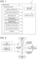
- Fig. 1 is a block diagram of a mobile robot 1 according to one embodiment of the present invention.
- the mobile robot 1 as a mobile body of the present embodiment includes, as shown in Fig. 1 , a control section 2, a detection section 3, and a mobile section 4.
- the control section 2 and the detection section 3 form an information processing device.
- the detection section 3 has a laser scanner configured to emit beams to the periphery of the mobile robot 1 to detect the presence or absence of an object, and acquires detection information on each emitted beam.
- the mobile robot 1 estimates a self-position by a SLAM technique and an odometry.
- the mobile section 4 has a driver such as a motor and a wheel to be rotatably driven by the driver, and causes the mobile robot 1 to autonomously travel and to acquire a movement amount (the detection information) by means of a wheel rotation angle to estimate the self-position by the odometry.
- a driver such as a motor and a wheel to be rotatably driven by the driver
- the control section 2 includes an arithmetic section such as a CPU and a storage section such as a ROM or a RAM to control operation of the mobile robot 1, and includes a mobile controller 21 configured to control the mobile section 4 and a detection controller 22 configured to control the detection section 3. Further, the control section 2 includes a map producer 23 configured to produce a map of the periphery of the mobile robot 1 as described later and an existing map self-position estimator 24 and a current map self-position estimator 25 configured to estimate the self-position of the mobile robot 1.
- control section 2 includes a reliability evaluator 26 configured to evaluate the reliability of each of the self-positions estimated by the existing map self-position estimator 24 and the current map self-position estimator 25, a self-position updater 27 configured to update either one of the self-positions based on the reliability evaluated by the reliability evaluator 26, and a storage 28 configured to store the detection information acquired by the detection section 3, the map produced by the map producer 23, various types of data and the like.
- a reliability evaluator 26 configured to evaluate the reliability of each of the self-positions estimated by the existing map self-position estimator 24 and the current map self-position estimator 25, a self-position updater 27 configured to update either one of the self-positions based on the reliability evaluated by the reliability evaluator 26, and a storage 28 configured to store the detection information acquired by the detection section 3, the map produced by the map producer 23, various types of data and the like.
- the map produced by the map producer 23 an optional map such as an occupied grid map or a point cloud map can be utilized.
- the detection section 3 includes the laser scanner (light detection and ranging (LIDAR)) configured to circumferentially emit laser light such as infrared laser to measure a distance to the object.
- This laser scanner takes sensor center and orientation which are the self-position as a reference position (x, y, ⁇ ) T , and detects the presence or absence and position of the object based on an angle (a direction) about the sensor center.
- a detection value for a single cycle e.g., a single rotation, 360°
- a predetermined resolution e.g. 1°
- the mobile section 4 detects the rotation angle of the wheel rotatably driven by the driver, thereby acquiring the movement amount of the mobile robot 1 and storing such a movement amount as odometry information (the detection information) in the storage 28.
- the self-position is estimated based on the scan information and the odometry information as the detection information while a current map is sequentially produced by the SLAM technique.
- the self-position is estimated in such a manner that an existing map (a reference map) produced previously, repeatedly updated by a later-described method, and stored in the storage 28 and the detection information are checked against each other.
- the existing map is not necessarily the map previously produced, repeatedly updated by the later-described method, and stored in the storage 28, and may be one transferred from the outside of the mobile robot 1, for example. In other words, it may only be required that the existing map is previously produced and is stored in the storage 28.
- Fig. 2 is a conceptual diagram showing operation of the mobile robot 1 in map production and self-position estimation.
- the mobile robot 1 estimates the self-position by the SLAM and the LOC.
- the SLAM the current map is produced, and the self-position is estimated based on the produced current map.
- the LOC the self-position is estimated by checking against the reference map (the existing map). After self-position estimation by the SLAM and the LOC, the reliability of each self-position is evaluated and updated.
- the mobile robot 1 of the present embodiment estimates the self-position on the current map and the reference map by the SLAM and the LOC in parallel.
- Figs. 3 and 4 are conceptual diagrams showing the state of the mobile robot 1 in self-position estimation.
- (A) is a point cloud showing the object on the current map or the reference map
- (B) is a point cloud in the scan information detected by the detection section 3
- (C) shows a state in which the point clouds of (A) and (B) overlap with each other.
- the case of using scan matching by an ICP as a positioning method will be described herein by way of example.
- the self-position of the mobile robot 1 is determined by positioning by the ICP based on the shape of the point cloud on the current map or the reference map and the shape of the point cloud in the scan information.
- the self-position (the movement amount) of the mobile robot 1 is estimated such that the degree of overlap between a current map (or a previously-produced reference map) produced at the first position and scan information scanned at the second position is optimal.
- the sequentially-produced current map and the scan information are checked against each other, and in this manner, the current map is repeatedly updated while the self-position is estimated.
- the LOC the previously-produced reference map and the scan information are checked against each other, and in this manner, the self-position on the reference map is estimated.
- Fig. 3 shows the state of scan matching by the SLAM, and shows a favorable matching state in which the point cloud on the current map and the point cloud in the scan information favorably overlap with each other.
- Fig. 4 shows the state of scan matching by the LOC, and shows an unfavorable matching state in which the point cloud on the reference map and the point cloud in the scan information partially shift from each other. That is, the scan information at portions indicated by positions A1, A2 in Fig. 4(B) shifts from the reference map of Fig. 4(A) , and this shows the probability of a change between the position or shape of the object present on the previously-produced reference map and the current position or shape of the object.
- the matching score is calculated for the estimated self-position, and the reliability is set based on the matching score.
- the reliability of each of the self-positions estimated by the SLAM and the LOC is evaluated, and either one of the self-positions is updated based on the evaluated reliability.
- the method for evaluating the reliability of each self-position and updating the self-position by the SLAM and the LOC as described above will be described later.
- the current map is produced and the self-position is estimated by the SLAM, and the self-position is estimated with reference to the reference map by the LOC.
- a better one of the self-positions estimated by these techniques is employed.
- the SLAM on the current map and self-position estimation on the reference map are performed in parallel, and therefore, the effect of these techniques complementing each other is obtained. That is, even when either one of the SLAM or the LOC fails to estimate the self-position, if the other one of the SLAM or the LOC successfully estimates the self-position, the mobile robot 1 can return to an accurate position, and therefore, robustness is improved.
- the scan information or the odometry information as measurement data is in an unfavorable state, a great error in the self-position estimated by the SLAM is caused. This might lead to distortion of the produced current map. In this case, it is difficult for the mobile robot 1 to return to the accurate position even with normal scan information. For this reason, the LOC is used in combination so that the reference map can be taken as a reference. With the normal scan information, the probability of accurately estimating the self-position can be increased. Further, when the mobile robot 1 moves out of the area of the reference map, scan matching cannot be performed due to the absence of the map, and for this reason, the self-position is estimated only based on the odometry information by the LOC.
- the SLAM is used in combination so that the position of the mobile robot 1 can be continuously estimated.
- the LOC takes the self-position estimated by the SLAM, and in this manner, the self-position can be obtained with a higher accuracy than that in the case of only the odometry information. This also leads to the effect of the mobile robot 1 easily returning to the accurate position when the mobile robot 1 returns to the inside of the area of the reference map.
- Fig. 5 is a flowchart showing operation of the mobile robot 1. Note that description of operation relating to traveling of the mobile robot 1 will be omitted and description will be made herein focusing on the steps of estimating the self-position and producing the current map during traveling.
- the detection section 3 is drivably controlled by the detection controller 22 to start detection of the peripheral object (a detection information acquisition step: a step ST11).
- the detection controller 22 acquires the scan information (the detection information) obtained by detection of the peripheral object by the detection section 3, and stores the acquired scan information in the storage 28. Further, the detection controller 22 acquires the odometry information (the detection information) obtained by detection of the movement amount from the rotation angle of the wheel of the mobile section 4, and stores the acquired odometry information in the storage 28.
- the control section 2 estimates the self-position of the mobile robot 1 based on the scan information and the odometry information stored in the storage 28, the produced current map, and the reference map (the existing map) stored in the storage 28 (a self-position estimation step: a step ST12).
- steps ST21 to ST23 as the steps of estimating the self-position by the SLAM and steps ST31 to ST33 as the steps of estimating the self-position by the LOC are executed in parallel.
- the control section 2 causes the current map self-position estimator 25 to estimate the current self-position of the mobile robot 1 based on the current map produced so far, the scan information, and the odometry information. Further, the control section 2 causes the map producer 23 to produce the current map, and stores the produced current map in the storage 28 (a current map production step and a self-position estimation step based on the current map: the step ST21). Next, the current map self-position estimator 25 calculates the movement amount between the calculated self-position and the self-position at a previous time point based on these self-positions (a movement amount calculation step: the step ST22).
- the control section 2 causes the reliability evaluator 26 to evaluate the reliability of the self-position (a reliability evaluation step: the step ST23).
- the reliability evaluator 26 calculates the reliability of the self-position based on the result of scan matching as described above. For example, the reliability may be determined from the matching score, or may be determined from the number of matched points. The reliability increases as the matching score decreases in the former case, and proper conversion is performed such that the reliability increases as the number of points increases in the latter case. In a case where the reliability is lower than a predetermined threshold, the reliability may be zero.
- the control section 2 causes the existing map self-position estimator 24 to estimate the current self-position of the mobile robot 1 based on the reference map, the scan information, and the odometry information stored in the storage 28 (a self-position estimation step based on the reference map: the step ST31).
- the existing map self-position estimator 24 calculates the movement amount between the calculated self-position and the self-position at a previous time point based on these self-positions (a movement amount calculation step: the step ST32).
- the control section 2 causes the reliability evaluator 26 to evaluate the reliability of the self-position (a reliability evaluation step: the step ST33).
- the reliability evaluator 26 calculates the reliability of the self-position based on the result of scan matching as described above. For example, the reliability may be determined from the matching score, or may be determined from the number of matched points. The reliability increases as the matching score decreases in the former case, and proper conversion is performed such that the reliability increases as the number of points increases in the latter case. In a case where the reliability is lower than a predetermined threshold, the reliability may be zero.
- the control section 2 causes the self-position updater 27 to update at least either one of the self-positions based on the weight on each of the self-positions obtained by the SLAM and the LOC (a self-position updating step: a step ST14).
- the self-position updater 27 updates each self-position based on the movement amount of each self-position calculated at the movement amount calculation step (the steps ST23, ST32) and the weight set to each self-position at the weighting step (the step ST13). Note that at the self-position updating step (the step ST14), the self-position with a lower reliability may be updated (rewritten) with the self-position with a higher reliability regardless of the weight on each self-position.
- This case is equivalent to the case where the reliability lower than the threshold is set to zero as described above.
- the reliability of each of the self-positions obtained by the SLAM and the LOC is higher than the threshold
- the self-position estimated by each of these techniques may be directly used. Note that in a case where the reliability of one of the self-positions becomes lower than the threshold, such a self-position is rewritten with the other self-position.
- control section 2 determines, at a step ST15, whether or not traveling of the mobile robot 1 is to be continued. If traveling is continued at the step ST15, the process returns to the detection information acquisition step (the step ST11) to repeat the above-described steps. If traveling is not continued at the step ST15, the control section 2 stops traveling of the mobile robot 1 and stops operation of each section.
- the mobile robot examples include a mobile robot such as a service robot or a home robot. More specifically, the examples include a cleaning robot, a security robot, a conveyance robot, and a guide robot. Further, the mobile body may be a self-driving car or a service car. In addition, a movement area of the mobile body is not limited to a two-dimensional planar space, and may be a three-dimensional space. In this case, the mobile body may be a flying body such as a drone. That is, in the above-described embodiment, the example using 2D-SLAM has been described as the SLAM technique. However, the information processing device of the present invention is also applicable to 3D-SLAM targeted for the three-dimensional space.
- the mobile robot 1 includes the control section 2, and the control section 2 is provided with the map producer 23, the self-position estimators 24, 25 and the like.
- the information processing device is not necessarily provided in the mobile robot 1, and may be provided at other types of equipment communicable with the mobile robot 1 and it may be configured such that the mobile robot 1 autonomously travels based on a map produced by the other types of equipment.
- the mobile body does not necessarily include the mobile section, and may be configured to detect the periphery thereof while a user is manually moving, e.g., a wagon on which the detection section is placed.
- the point cloud map is used as the reference map (the existing map) and the current map, but each of these maps is not limited to the point cloud map and may be the occupied grid map or other maps.
- the detection section having the laser scanner has been described by way of example, but the present invention is not limited to such a detection section, and any other detection section such as various distance sensors or imaging devices can be utilized.
- the odometry information is acquired based on the rotation angle of the wheel of the mobile section, but the present invention is not limited to such a configuration and a movement amount measured by an optical section or a rotation angle measured by a gyroscope or an inertial measurement unit (IMU) may be utilized for the odometry information.
- IMU inertial measurement unit
- the self-position updater 27 calculates the movement amount of each of the self-positions estimated by the SLAM and the LOC, and updates either one of the self-positions based on the calculated movement amount.
- the self-position updater 27 may update, regardless of the movement amount, the self-position with the estimated self-positions overlapping with each other on the reference map or the current map. That is, in the above-described embodiment, the self-position is updated after the movement amount has been calculated from each self-position because it is difficult to cause the self-positions to overlap with each other on the reference map or the current map due to a difference in shape between these maps.
- the self-positions can directly overlap with each other on these maps, and therefore, the self-position can be updated without calculation of the movement amount.
- the maps are combined by pose graph combination according to the self-positions estimated by the SLAM and the LOC.
- the map combination method is not limited to use of the pose graphs, and other combination methods may be employed.
- the present invention can be suitably utilized for an information processing device and a mobile robot capable of ensuring the accuracy of estimation of a self-position even with an environmental change and maintaining the consistency of the self-position on a map.
Landscapes
- Engineering & Computer Science (AREA)
- Radar, Positioning & Navigation (AREA)
- Remote Sensing (AREA)
- Physics & Mathematics (AREA)
- General Physics & Mathematics (AREA)
- Automation & Control Theory (AREA)
- Electromagnetism (AREA)
- Aviation & Aerospace Engineering (AREA)
- Computer Networks & Wireless Communication (AREA)
- Computer Vision & Pattern Recognition (AREA)
- Theoretical Computer Science (AREA)
- Optics & Photonics (AREA)
- Multimedia (AREA)
- Control Of Position, Course, Altitude, Or Attitude Of Moving Bodies (AREA)
- Optical Radar Systems And Details Thereof (AREA)
- General Factory Administration (AREA)
Description
- The present invention relates to an information processing device and a mobile robot.
- Typically, a technique called simultaneous localization and mapping (SLAM) and employed for self-position estimation and environmental map production has been used as the technique of causing an autonomously-travelable mobile body such as a mobile robot or a self-driving car to autonomously travel. As an environmental map, an occupied grid map or a point cloud map produced based on the presence or absence of an object in a movement area of the mobile body is used in some cases. In the occupied grid map, a plane or a space in the movement area is divided into multiple sections (cells) and is stored, and a cell value corresponding to the presence or absence of the object is assigned to each divided section. The point cloud map represents, as a point (coordinates) discretized into each minute region, the object present in the plane or the space in the movement area, and as the map, utilizes point cloud data which is the group of these points.
- In a case where the mobile body autonomously travels to a destination, a movement path from a current location to the destination is obtained, and the mobile body travels to the destination along such a movement path. In this case, for efficient movement, the movement path is calculated using a map (an existing map) produced in advance, and the mobile body travels while checking (estimating) a self-position on the existing map. Such self-position estimation on the existing map is an essential technique for autonomous traveling of the mobile body.
- As the technique of estimating the self-position of the mobile body, a method in which positioning of the mobile body on the environmental map prepared in advance is performed using distance data (detection information) obtained from the output of a distance sensor and the self-position is estimated thereafter is generally employed. For example, as the method for positioning the mobile body, a method called an iterative closest point (ICP) is employed. In this method, the position of the mobile body is determined by checking against a characteristic portion of the environmental map based on a geometrical characteristic of the group of points extracted from the point cloud data (see, e.g., Patent Literature 1). In the self-position estimation method described in
Patent Literature 1, the periphery of the mobile body is observed by the distance sensor, and in this manner, multiple three-dimensional points indicating an object surface are acquired. Based on such an observation result, characteristic amounts of the multiple three-dimensional points are calculated. Multiple ones of the three-dimensional points of which characteristic amounts are equal to or greater than a characteristic amount threshold are extracted from both of a close range and a long range. The self-position is estimated by matching among the extracted multiple three-dimensional points and the multiple three-dimensional points on the environmental map. - As the technique of estimating the self-position of the mobile body, there is a method called an odometry. In this method, a movement amount (the detection information) is calculated using a wheel rotation angle, and the self-position is estimated based on the movement amount. In this method, the position of the mobile body is determined by checking of self-position information based on the movement amount against the environmental map. However, in the self-position estimation method based on the odometry, an odometry error is caused in a case where the vehicle turns or a wheel idles. This degrades the accuracy of estimation of the self-position. For this reason, a technique has been proposed, in which self-position estimation based on the odometry and positioning based on the ICP by means of the distance sensor as described above are used in combination to improve the accuracy of estimation of the self-position (see, e.g., Patent Literature 2).
-
- PATENT LITERATURE 1:
JP-A-2017-083230 - PATENT LITERATURE 2:
JP-A-2018-084492 - Document
CN105953798 B relates to the technical field of positioning and navigation of mobile robots, and in particular to a determination method and apparatus for poses of a mobile robot. - Document
WO2018/166287 A1 andUS2020/081136 A relate to the technical field of unmanned aerial vehicle (UAV), and in particular, to a positioning method and a positioning device of a UAV. - The invention is set out in the appended set of claims.
- However, any of the typical techniques described in
Patent Literatures - An object of the present invention is to provide an information processing device and a mobile robot capable of ensuring the accuracy of estimation of a self-position even with an environmental change and maintaining the consistency of the self-position on a map.
- The information processing device of the present invention is an information processing device for estimating a self-position of a mobile body based on a map of environment where the mobile body travels. The information processing device includes a detection section configured to detect, as detection information, a distance to an object at the periphery of the mobile body and the direction of the object and a control section configured to control the detection section. The control section includes a storage configured to store the detection information, which has been detected by the detection section, in chronological order and store a map, a map producer configured to produce a map of the periphery of the mobile body based on the detection information stored in the storage and store the map in the storage, an existing map self-position estimator configured to estimate a current self-position of the mobile body based on an existing map previously produced and stored in the storage, a current map self-position estimator configured to estimate the current self-position of the mobile body based on a current map being currently produced and stored in the storage, a reliability evaluator configured to evaluate the reliability of each self-position estimated by the existing map self-position estimator and the current map self-position estimator, and a self-position updater configured to update either one of the self-positions based on the reliability evaluated by the reliability evaluator.
- According to such an aspect of the present invention, the self-position updater updates either one of the self-positions estimated by the existing map self-position estimator and the current map self-position estimator based on the reliability of each of the self-positions evaluated by the reliability evaluator. Thus, the consistency of each of the self-positions estimated by the existing map self-position estimator and the current map self-position estimator can be established. Thus, even in a case where the environment where the mobile body repeatedly moves has been changed, the reliability of the self-position is evaluated based on both of the existing map and the current map so that the accuracy of estimation of the self-position according to an environmental change can be improved.
- In the present invention, the self-position updater preferably calculates a movement amount of each of the self-positions estimated by the existing map self-position estimator and the current map self-position estimator, and preferably updates either one of the self-positions based on the calculated movement amount.
- According to such a configuration, the self-position updater calculates the movement amount of each of the self-positions estimated by the existing map self-position estimator and the current map self-position estimator, and updates either one of the self-positions based on the calculated movement amount. Thus, the consistency of each self-position can be established even in a case where the existing map and the current map are different from each other in a shape. That is, even at the same location, the shapes of the existing map and the current map are not coincident with each other in many cases due to a different traveling path of the mobile robot and different sensor noise. With a difference in a map shape, a map consistency cannot be always established even when the self-position on one map is directly used for the other map. On the other hand, the movement amount of the self-position on the existing map and the current map is calculated, and each self-position is updated based on such a movement amount. Thus, the accuracy of estimation of the self-position can be enhanced while an error is reduced.
- In the present invention, the self-position updater preferably updates the self-position evaluated as a lower reliability by the reliability evaluator based on the self-position evaluated as a higher reliability.
- According to such a configuration, the self-position updater updates the self-position evaluated as a lower reliability by the reliability evaluator based on the self-position evaluated as a higher reliability. Thus, the accuracy of estimation of each self-position can be improved.
- In the present invention, the reliability evaluator preferably sets a weight indicating the reliability of each self-position to a greater weight as the reliability of each self-position increases, and preferably sets the weight to a smaller weight as the reliability of each self-position decreases. The self-position updater preferably updates at least either one of the self-positions based on the weight set by the reliability evaluator.
- According to such a configuration, the self-position updater updates at least either one of the self-positions estimated by the existing map self-position estimator and the current map self-position estimator based on the weight indicating the reliability of each self-position and set by the reliability evaluator. Thus, the reliability of each self-position can be evaluated in a stepwise manner, and the consistency of each self-position can be established with a favorable efficiency.
- The mobile robot of the present invention includes the above-described information processing device and a mobile section configured to move the mobile body.
- According to such an aspect of the present invention, the mobile robot includes the information processing device and the mobile section. The self-position updater included in the control section of the information processing device updates either one of the self-positions estimated by the existing map self-position estimator and the current map self-position estimator based on the reliability of each self-position evaluated by the reliability evaluator, and therefore, the consistency of each of the self-positions estimated by the existing map self-position estimator and the current map self-position estimator can be established.
-
-
Fig. 1 is a block diagram of a mobile robot according to one embodiment of the present invention. -
Fig. 2 is a conceptual diagram showing operation of the mobile robot in map production and self-position estimation. -
Fig. 3 is a conceptual diagram showing the state of the mobile robot in self-position estimation. -
Fig. 4 is a conceptual diagram showing the state of the mobile robot in self-position estimation. -
Fig. 5 is a flowchart showing operation of the mobile robot. - Hereinafter, one embodiment of the present invention will be described based on
Figs. 1 to 5 . -
Fig. 1 is a block diagram of amobile robot 1 according to one embodiment of the present invention. - The
mobile robot 1 as a mobile body of the present embodiment includes, as shown inFig. 1 , acontrol section 2, adetection section 3, and amobile section 4. Thecontrol section 2 and thedetection section 3 form an information processing device. Thedetection section 3 has a laser scanner configured to emit beams to the periphery of themobile robot 1 to detect the presence or absence of an object, and acquires detection information on each emitted beam. Themobile robot 1 estimates a self-position by a SLAM technique and an odometry. Themobile section 4 has a driver such as a motor and a wheel to be rotatably driven by the driver, and causes themobile robot 1 to autonomously travel and to acquire a movement amount (the detection information) by means of a wheel rotation angle to estimate the self-position by the odometry. - The
control section 2 includes an arithmetic section such as a CPU and a storage section such as a ROM or a RAM to control operation of themobile robot 1, and includes amobile controller 21 configured to control themobile section 4 and adetection controller 22 configured to control thedetection section 3. Further, thecontrol section 2 includes amap producer 23 configured to produce a map of the periphery of themobile robot 1 as described later and an existing map self-position estimator 24 and a current map self-position estimator 25 configured to estimate the self-position of themobile robot 1. In addition, thecontrol section 2 includes areliability evaluator 26 configured to evaluate the reliability of each of the self-positions estimated by the existing map self-position estimator 24 and the current map self-position estimator 25, a self-position updater 27 configured to update either one of the self-positions based on the reliability evaluated by thereliability evaluator 26, and astorage 28 configured to store the detection information acquired by thedetection section 3, the map produced by themap producer 23, various types of data and the like. As the map produced by themap producer 23, an optional map such as an occupied grid map or a point cloud map can be utilized. Hereinafter, the case of producing the point cloud map will be described. - For example, the
detection section 3 includes the laser scanner (light detection and ranging (LIDAR)) configured to circumferentially emit laser light such as infrared laser to measure a distance to the object. This laser scanner takes sensor center and orientation which are the self-position as a reference position (x, y, θ)T, and detects the presence or absence and position of the object based on an angle (a direction) about the sensor center. In such object detection (hereinafter sometimes merely referred to as a scan), a detection value for a single cycle (e.g., a single rotation, 360°) of the laser scanner is taken as a single unit (a single scan) based on the beams emitted with a predetermined resolution (e.g., 1°) in detection for the single cycle, and as scan information (the detection information), is stored in chronological order in thestorage 28. - The
mobile section 4 detects the rotation angle of the wheel rotatably driven by the driver, thereby acquiring the movement amount of themobile robot 1 and storing such a movement amount as odometry information (the detection information) in thestorage 28. In themobile robot 1 of the present embodiment, the self-position is estimated based on the scan information and the odometry information as the detection information while a current map is sequentially produced by the SLAM technique. In addition, the self-position is estimated in such a manner that an existing map (a reference map) produced previously, repeatedly updated by a later-described method, and stored in thestorage 28 and the detection information are checked against each other. Hereinafter, self-position estimation by the SLAM technique will be sometimes merely referred to as "SLAM," and self-position estimation by checking against the reference map will be sometimes merely referred to as "LOC" (localization). A technique for self-position estimation and map production by use of both of the SLAM and the LOC in combination will be described with reference toFigs. 2 to 5 . - Note that the existing map is not necessarily the map previously produced, repeatedly updated by the later-described method, and stored in the
storage 28, and may be one transferred from the outside of themobile robot 1, for example. In other words, it may only be required that the existing map is previously produced and is stored in thestorage 28. -
Fig. 2 is a conceptual diagram showing operation of themobile robot 1 in map production and self-position estimation. As shown inFig. 2 , when themobile robot 1 acquires the scan information from thedetection section 3 and the odometry information from themobile section 4, themobile robot 1 estimates the self-position by the SLAM and the LOC. In the SLAM, the current map is produced, and the self-position is estimated based on the produced current map. In the LOC, the self-position is estimated by checking against the reference map (the existing map). After self-position estimation by the SLAM and the LOC, the reliability of each self-position is evaluated and updated. As described above, themobile robot 1 of the present embodiment estimates the self-position on the current map and the reference map by the SLAM and the LOC in parallel. -
Figs. 3 and4 are conceptual diagrams showing the state of themobile robot 1 in self-position estimation. In each ofFigs. 3 and4, (A) is a point cloud showing the object on the current map or the reference map, (B) is a point cloud in the scan information detected by thedetection section 3, and (C) shows a state in which the point clouds of (A) and (B) overlap with each other. The case of using scan matching by an ICP as a positioning method will be described herein by way of example. For example, the self-position of themobile robot 1 is determined by positioning by the ICP based on the shape of the point cloud on the current map or the reference map and the shape of the point cloud in the scan information. In scan matching, when themobile robot 1 has moved from a first position to a second position, the self-position (the movement amount) of themobile robot 1 is estimated such that the degree of overlap between a current map (or a previously-produced reference map) produced at the first position and scan information scanned at the second position is optimal. In the SLAM, the sequentially-produced current map and the scan information are checked against each other, and in this manner, the current map is repeatedly updated while the self-position is estimated. On the other hand, in the LOC, the previously-produced reference map and the scan information are checked against each other, and in this manner, the self-position on the reference map is estimated. -
Fig. 3 shows the state of scan matching by the SLAM, and shows a favorable matching state in which the point cloud on the current map and the point cloud in the scan information favorably overlap with each other.Fig. 4 shows the state of scan matching by the LOC, and shows an unfavorable matching state in which the point cloud on the reference map and the point cloud in the scan information partially shift from each other. That is, the scan information at portions indicated by positions A1, A2 inFig. 4(B) shifts from the reference map ofFig. 4(A) , and this shows the probability of a change between the position or shape of the object present on the previously-produced reference map and the current position or shape of the object. However, there is a probability that in the LOC based on the reference map, the self-position cannot be accurately estimated according to an environmental change such as an object position change as described above. For this reason, in, e.g., scan matching by the ICP as described above, the score of matching of the scan information with the reference map is calculated by Expression (1) below. This matching score G(x) decreases as the state of matching becomes better as inFig. 3 , and increases as the state of matching becomes worse as inFig. 4 .
[Expression 1]
- In Expression (1),
- x: a robot position (x, y, θ)T at a time point t,
- R, t: a rotation matrix and a translation component of x represented by Expression (2) below,
- pi: an i-th point in a scan at the time point t, and
- qji: a point in a scan at a time point t - 1 corresponding to pi, ji is the number of a point corresponding to i.
- As described above, the matching score is calculated for the estimated self-position, and the reliability is set based on the matching score. In this manner, the reliability of each of the self-positions estimated by the SLAM and the LOC is evaluated, and either one of the self-positions is updated based on the evaluated reliability. The method for evaluating the reliability of each self-position and updating the self-position by the SLAM and the LOC as described above will be described later.
- In the
mobile robot 1 of the present embodiment, the current map is produced and the self-position is estimated by the SLAM, and the self-position is estimated with reference to the reference map by the LOC. A better one of the self-positions estimated by these techniques is employed. According to such a self-position estimation method, the SLAM on the current map and self-position estimation on the reference map are performed in parallel, and therefore, the effect of these techniques complementing each other is obtained. That is, even when either one of the SLAM or the LOC fails to estimate the self-position, if the other one of the SLAM or the LOC successfully estimates the self-position, themobile robot 1 can return to an accurate position, and therefore, robustness is improved. - If the scan information or the odometry information as measurement data is in an unfavorable state, a great error in the self-position estimated by the SLAM is caused. This might lead to distortion of the produced current map. In this case, it is difficult for the
mobile robot 1 to return to the accurate position even with normal scan information. For this reason, the LOC is used in combination so that the reference map can be taken as a reference. With the normal scan information, the probability of accurately estimating the self-position can be increased. Further, when themobile robot 1 moves out of the area of the reference map, scan matching cannot be performed due to the absence of the map, and for this reason, the self-position is estimated only based on the odometry information by the LOC. Only with the odometry information, there is a probability that a position error is accumulated and the self-position is lost. For this reason, the SLAM is used in combination so that the position of themobile robot 1 can be continuously estimated. Thus, the LOC takes the self-position estimated by the SLAM, and in this manner, the self-position can be obtained with a higher accuracy than that in the case of only the odometry information. This also leads to the effect of themobile robot 1 easily returning to the accurate position when themobile robot 1 returns to the inside of the area of the reference map. - Next, operation of the
mobile robot 1 will be described in detail with reference toFig. 5. Fig. 5 is a flowchart showing operation of themobile robot 1. Note that description of operation relating to traveling of themobile robot 1 will be omitted and description will be made herein focusing on the steps of estimating the self-position and producing the current map during traveling. - When the mobile section is drivably controlled by the
mobile controller 21 of thecontrol section 2 and themobile robot 1 starts traveling accordingly, thedetection section 3 is drivably controlled by thedetection controller 22 to start detection of the peripheral object (a detection information acquisition step: a step ST11). At the detection information acquisition step (the step ST11), thedetection controller 22 acquires the scan information (the detection information) obtained by detection of the peripheral object by thedetection section 3, and stores the acquired scan information in thestorage 28. Further, thedetection controller 22 acquires the odometry information (the detection information) obtained by detection of the movement amount from the rotation angle of the wheel of themobile section 4, and stores the acquired odometry information in thestorage 28. - The
control section 2 estimates the self-position of themobile robot 1 based on the scan information and the odometry information stored in thestorage 28, the produced current map, and the reference map (the existing map) stored in the storage 28 (a self-position estimation step: a step ST12). At the self-position estimation step (the step ST12), steps ST21 to ST23 as the steps of estimating the self-position by the SLAM and steps ST31 to ST33 as the steps of estimating the self-position by the LOC are executed in parallel. - As the steps of estimating the self-position by the SLAM, the
control section 2 causes the current map self-position estimator 25 to estimate the current self-position of themobile robot 1 based on the current map produced so far, the scan information, and the odometry information. Further, thecontrol section 2 causes themap producer 23 to produce the current map, and stores the produced current map in the storage 28 (a current map production step and a self-position estimation step based on the current map: the step ST21). Next, the current map self-position estimator 25 calculates the movement amount between the calculated self-position and the self-position at a previous time point based on these self-positions (a movement amount calculation step: the step ST22). When the current self-position is estimated by the SLAM as described above, thecontrol section 2 causes thereliability evaluator 26 to evaluate the reliability of the self-position (a reliability evaluation step: the step ST23). At the reliability evaluation step (the step ST23), thereliability evaluator 26 calculates the reliability of the self-position based on the result of scan matching as described above. For example, the reliability may be determined from the matching score, or may be determined from the number of matched points. The reliability increases as the matching score decreases in the former case, and proper conversion is performed such that the reliability increases as the number of points increases in the latter case. In a case where the reliability is lower than a predetermined threshold, the reliability may be zero. - As the steps of estimating the self-position by the LOC, the
control section 2 causes the existing map self-position estimator 24 to estimate the current self-position of themobile robot 1 based on the reference map, the scan information, and the odometry information stored in the storage 28 (a self-position estimation step based on the reference map: the step ST31). Next, the existing map self-position estimator 24 calculates the movement amount between the calculated self-position and the self-position at a previous time point based on these self-positions (a movement amount calculation step: the step ST32). When the current self-position is estimated by the LOC as described above, thecontrol section 2 causes thereliability evaluator 26 to evaluate the reliability of the self-position (a reliability evaluation step: the step ST33). At the reliability evaluation step (the step ST33), thereliability evaluator 26 calculates the reliability of the self-position based on the result of scan matching as described above. For example, the reliability may be determined from the matching score, or may be determined from the number of matched points. The reliability increases as the matching score decreases in the former case, and proper conversion is performed such that the reliability increases as the number of points increases in the latter case. In a case where the reliability is lower than a predetermined threshold, the reliability may be zero. - When each self-position is estimated by the SLAM and the LOC and the reliability of each self-position is evaluated as described above, the
control section 2 causes thereliability evaluator 26 to set, based on the reliability of each of the self-positions obtained by the SLAM and the LOC, a greater weight to each self-position as the reliability increases (a weighting step: a step ST13). That is, when the reliability of the self-position obtained by the SLAM is 80% and the reliability of the self-position obtained by the LOC is 60%, the weight on the self-position obtained by the SLAM is set as 0.57 (= 80/(80 + 60)) and the weight on the self-position obtained by the LOC is set as 0.43 (= 60/(80 + 60)), for example. - Next, the
control section 2 causes the self-position updater 27 to update at least either one of the self-positions based on the weight on each of the self-positions obtained by the SLAM and the LOC (a self-position updating step: a step ST14). The self-position updater 27 updates each self-position based on the movement amount of each self-position calculated at the movement amount calculation step (the steps ST23, ST32) and the weight set to each self-position at the weighting step (the step ST13). Note that at the self-position updating step (the step ST14), the self-position with a lower reliability may be updated (rewritten) with the self-position with a higher reliability regardless of the weight on each self-position. This case is equivalent to the case where the reliability lower than the threshold is set to zero as described above. In a case where the reliability of each of the self-positions obtained by the SLAM and the LOC is higher than the threshold, the self-position estimated by each of these techniques may be directly used. Note that in a case where the reliability of one of the self-positions becomes lower than the threshold, such a self-position is rewritten with the other self-position. - Next, the
control section 2 determines, at a step ST15, whether or not traveling of themobile robot 1 is to be continued. If traveling is continued at the step ST15, the process returns to the detection information acquisition step (the step ST11) to repeat the above-described steps. If traveling is not continued at the step ST15, thecontrol section 2 stops traveling of themobile robot 1 and stops operation of each section. - According to the present embodiment as described above, the following features/advantageous effects can be provided.
- (1) The
mobile robot 1 causes the self-position updater 27 to update either one of the self-positions based on the reliability of each self-position estimated by the SLAM and the LOC and evaluated by thereliability evaluator 26 of thecontrol section 2. Thus, consistency between the self-positions estimated by the existing map self-position estimator 24 and the current map self-position estimator 25 can be established. Thus, even in a case where environment where themobile robot 1 repeatedly moves has been changed, themobile robot 1 evaluates the reliability of the self-position based on both of the reference map and the current map so that the accuracy of estimation of the self-position according to an environmental change can be improved. - (2) The self-
position updater 27 of thecontrol section 2 calculates the movement amount of each of the self-positions estimated by the SLAM and the LOC, and updates either one of the self-positions based on the calculated movement amount. Thus, the consistency of each self-position can be established even in a case where the reference map and the current map are different from each other in a shape, and the accuracy of estimation of the self-position can be enhanced while an error is reduced. - (3) The self-
position updater 27 updates at least either one of the self-positions estimated by the SLAM and the LOC based on the weight indicating the reliability of each self-position and set by thereliability evaluator 26. Thus, the reliability of each self-position can be evaluated in a stepwise manner, and the consistency of each self-position can be established with a favorable efficiency. The self-position updater 27 may rewrite the self-position with a lower reliability with the self-position with a higher reliability regardless of the weight on each self-position. This can reduce a calculation cost. - Note that the present invention is not limited to the above-described embodiment, and variations, modifications and the like within such a scope that the object of the present invention can be achieved are included in the present invention.
- For example, in the above-described embodiment, no specific example of the
mobile robot 1 has been described. Examples of the mobile robot (the mobile body) include a mobile robot such as a service robot or a home robot. More specifically, the examples include a cleaning robot, a security robot, a conveyance robot, and a guide robot. Further, the mobile body may be a self-driving car or a service car. In addition, a movement area of the mobile body is not limited to a two-dimensional planar space, and may be a three-dimensional space. In this case, the mobile body may be a flying body such as a drone. That is, in the above-described embodiment, the example using 2D-SLAM has been described as the SLAM technique. However, the information processing device of the present invention is also applicable to 3D-SLAM targeted for the three-dimensional space. - In the above-described embodiment, the
mobile robot 1 includes thecontrol section 2, and thecontrol section 2 is provided with themap producer 23, the self-position estimators mobile robot 1, and may be provided at other types of equipment communicable with themobile robot 1 and it may be configured such that themobile robot 1 autonomously travels based on a map produced by the other types of equipment. Moreover, the mobile body does not necessarily include the mobile section, and may be configured to detect the periphery thereof while a user is manually moving, e.g., a wagon on which the detection section is placed. - In the above-described embodiment, the point cloud map is used as the reference map (the existing map) and the current map, but each of these maps is not limited to the point cloud map and may be the occupied grid map or other maps. Moreover, in the above-described embodiment, the detection section having the laser scanner has been described by way of example, but the present invention is not limited to such a detection section, and any other detection section such as various distance sensors or imaging devices can be utilized. Further, in the above-described embodiment, the odometry information is acquired based on the rotation angle of the wheel of the mobile section, but the present invention is not limited to such a configuration and a movement amount measured by an optical section or a rotation angle measured by a gyroscope or an inertial measurement unit (IMU) may be utilized for the odometry information.
- In the above-described embodiment, the self-
position updater 27 calculates the movement amount of each of the self-positions estimated by the SLAM and the LOC, and updates either one of the self-positions based on the calculated movement amount. However, the self-position updater 27 may update, regardless of the movement amount, the self-position with the estimated self-positions overlapping with each other on the reference map or the current map. That is, in the above-described embodiment, the self-position is updated after the movement amount has been calculated from each self-position because it is difficult to cause the self-positions to overlap with each other on the reference map or the current map due to a difference in shape between these maps. However, as long as map coordinate systems of the reference map and the current map can be properly converted to each other, the self-positions (coordinate values) can directly overlap with each other on these maps, and therefore, the self-position can be updated without calculation of the movement amount. In addition, in the above-described embodiment, the maps are combined by pose graph combination according to the self-positions estimated by the SLAM and the LOC. However, the map combination method is not limited to use of the pose graphs, and other combination methods may be employed. - As described above, the present invention can be suitably utilized for an information processing device and a mobile robot capable of ensuring the accuracy of estimation of a self-position even with an environmental change and maintaining the consistency of the self-position on a map.
-
- 1
- Mobile Robot
- 2
- Control Section
- 3
- Detection Section
- 4
- Mobile Section
- 23
- Map Producer
- 24
- Existing Map Self-Position Estimator
- 25
- Current Map Self-Position Estimator
- 26
- Reliability Evaluator
- 27
- Self-Position Updater
- 28
- Storage

Claims (5)
- An information processing device for estimating a self-position of a mobile body based on a map of environment where the mobile body travels, comprising:a detection section (3) including at least one of a laser scanner, a distance sensor, and an imaging device configured to detect, as detection information, a distance to an object at a periphery of the mobile body and a direction of the object; anda control section (2) configured to control the detection section (3),wherein the control section (2) includesa storage (28) configured to store the detection information, which has been detected by the detection section (3), in chronological order and store a map,a map producer (23) configured to produce a map of the periphery of the mobile body based on the detection information stored in the storage (28) and store the map in the storage (28),characterized by:an existing map self-position estimator (24) configured to estimate a current self-position of the mobile body by matching an existing map previously produced and stored in the storage (28) with the detection information, the matching being made based on the shape of a point cloud on the existing map and the shape of a point cloud in the scan information detected by the detection section, using an iterative closest point algorithm,a current map self-position estimator (25) configured to estimate the current self-position of the mobile body by matching a current map being currently produced and stored in the storage (28) with the detection information, the matching being made based on the shape of a point cloud on the current map and the shape of the point cloud in the scan information detected by the detection section, using an iterative closest point algorithm,a reliability evaluator (26) configured to evaluate a reliability of each self-position estimated by the existing map self-position estimator (24) and the current map self-position estimator (25), anda self-position updater (27) configured to update either one of the self-positions based on the reliability evaluated by the reliability evaluator (26).
- The information processing device according to claim 1, wherein
the self-position updater (27) calculates a movement amount of each of the self-positions estimated by the existing map self-position estimator (24) and the current map self-position estimator (25), and updates either one of the self-positions based on the calculated movement amount. - The information processing device according to claim 1 or 2, wherein
the self-position updater (27) updates the self-position evaluated as a lower reliability by the reliability evaluator (26) based on the self-position evaluated as a higher reliability. - The information processing device according to any one of claims 1 to 3, whereinthe reliability evaluator (26) sets a weight indicating the reliability of each self-position to a greater weight as the reliability of each self-position increases, and sets the weight to a smaller weight as the reliability of each self-position decreases, andthe self-position updater (27) updates at least either one of the self-positions based on the weight set by the reliability evaluator (26).
- A mobile robot (1) comprising:the information processing device according to any one of claims 1 to 4; anda mobile section (4) configured to move the mobile body.
Applications Claiming Priority (1)
| Application Number | Priority Date | Filing Date | Title |
|---|---|---|---|
| PCT/JP2019/010328 WO2020183659A1 (en) | 2019-03-13 | 2019-03-13 | Information processing device and mobile robot |
Publications (3)
| Publication Number | Publication Date |
|---|---|
| EP3940422A1 EP3940422A1 (en) | 2022-01-19 |
| EP3940422A4 EP3940422A4 (en) | 2022-10-26 |
| EP3940422B1 true EP3940422B1 (en) | 2025-02-19 |
Family
ID=72426087
Family Applications (1)
| Application Number | Title | Priority Date | Filing Date |
|---|---|---|---|
| EP19919202.2A Active EP3940422B1 (en) | 2019-03-13 | 2019-03-13 | Information processing device and mobile robot |
Country Status (6)
| Country | Link |
|---|---|
| US (1) | US12265396B2 (en) |
| EP (1) | EP3940422B1 (en) |
| JP (1) | JP7133251B2 (en) |
| CN (1) | CN113454487B (en) |
| TW (1) | TWI772743B (en) |
| WO (1) | WO2020183659A1 (en) |
Families Citing this family (9)
| Publication number | Priority date | Publication date | Assignee | Title |
|---|---|---|---|---|
| US12085951B2 (en) * | 2019-06-14 | 2024-09-10 | Lg Electronics Inc. | Method of updating map in fusion SLAM and robot implementing same |
| CN114867989B (en) * | 2019-12-04 | 2024-12-27 | 日本先锋公司 | Information processing device, control method, program product and storage medium |
| JP7283579B2 (en) * | 2019-12-09 | 2023-05-30 | 日本電気株式会社 | Self-position estimation device, self-position estimation method and program |
| JP2022012173A (en) * | 2020-07-01 | 2022-01-17 | ソニーグループ株式会社 | Information processing device, information processing system, information processing method, and program |
| WO2022097765A1 (en) * | 2020-11-04 | 2022-05-12 | 주식회사 다비오 | Terminal device for indoor positioning based on object recognition, service server, and method therefor |
| TWI801829B (en) * | 2021-03-26 | 2023-05-11 | 大陸商信泰光學(深圳)有限公司 | Transfer apparatuses and methods thereof |
| JP7782547B2 (en) | 2021-03-26 | 2025-12-09 | ソニーグループ株式会社 | Information processing device, information processing method, and mobile device |
| EP4359822A4 (en) * | 2021-08-09 | 2024-10-30 | Zhejiang Huaray Technology Co., Ltd. | SYSTEMS AND METHODS FOR DETERMINING THE POSTURE OF A MOBILE PERSON |
| JP7424438B1 (en) | 2022-09-22 | 2024-01-30 | いすゞ自動車株式会社 | Vehicle position estimation device |
Family Cites Families (31)
| Publication number | Priority date | Publication date | Assignee | Title |
|---|---|---|---|---|
| KR100843085B1 (en) * | 2006-06-20 | 2008-07-02 | 삼성전자주식회사 | Grid map preparation method and device of mobile robot and method and device for area separation |
| AU2009211435A1 (en) * | 2008-02-04 | 2009-08-13 | Tele Atlas B.V. | Method for map matching with sensor detected objects |
| GB2463481A (en) * | 2008-09-12 | 2010-03-17 | Geotate Bv | Means for estimating the location of an event using a satellite positioning system |
| JP5720292B2 (en) * | 2011-02-17 | 2015-05-20 | 富士通株式会社 | Estimated position evaluation system and program |
| GB201202344D0 (en) | 2012-02-10 | 2012-03-28 | Isis Innovation | Method of locating a sensor and related apparatus |
| US9215560B1 (en) * | 2012-07-12 | 2015-12-15 | two forty four a.m. LLC | System and method for device-centric location detection and geofencing |
| JP6136543B2 (en) * | 2013-05-01 | 2017-05-31 | 村田機械株式会社 | Autonomous mobile |
| JP6520048B2 (en) * | 2014-10-30 | 2019-05-29 | 村田機械株式会社 | Moving body |
| JP6553350B2 (en) * | 2014-11-26 | 2019-07-31 | アイシン精機株式会社 | Moving body |
| CN111380545B (en) * | 2015-02-10 | 2024-11-12 | 御眼视觉技术有限公司 | Method, server, autonomous vehicle and medium for autonomous vehicle navigation |
| DE112015006585B4 (en) * | 2015-06-04 | 2019-05-16 | Mitsubishi Electric Corporation | Driving assistance device, driving assistance server and driving assistance system |
| US10948302B2 (en) * | 2015-08-03 | 2021-03-16 | Tomtom Global Content B.V. | Methods and systems for generating and using localization reference data |
| JP6849330B2 (en) | 2015-08-28 | 2021-03-24 | パナソニック インテレクチュアル プロパティ コーポレーション オブ アメリカPanasonic Intellectual Property Corporation of America | Map generation method, self-position estimation method, robot system, and robot |
| JP6528641B2 (en) | 2015-10-26 | 2019-06-12 | トヨタ自動車株式会社 | Self-position estimation method |
| CA2981783A1 (en) * | 2015-10-30 | 2017-05-04 | Komatsu Ltd. | Control system of work machine, work machine, management system of work machine, and method of managing work machine |
| US10444758B2 (en) * | 2015-12-01 | 2019-10-15 | Ricoh Company, Ltd. | Autonomous traveling device |
| KR102415062B1 (en) * | 2015-12-07 | 2022-07-01 | 한화테크윈 주식회사 | Surveillance method |
| CN105953798B (en) * | 2016-04-19 | 2018-09-18 | 深圳市神州云海智能科技有限公司 | The pose of mobile robot determines method and apparatus |
| TWI622783B (en) * | 2016-05-24 | 2018-05-01 | 曦恩體感科技股份有限公司 | Hybrid positioning method and electronic device thereof |
| JP6834401B2 (en) | 2016-11-24 | 2021-02-24 | 日産自動車株式会社 | Self-position estimation method and self-position estimation device |
| JP6882664B2 (en) | 2017-02-07 | 2021-06-02 | 富士通株式会社 | Mobile body position estimation system, mobile body position estimation terminal device, information storage device, and mobile body position estimation method |
| CN106896391A (en) | 2017-03-14 | 2017-06-27 | 北京京东尚科信息技术有限公司 | The localization method and device of unmanned plane |
| CN106931975B (en) * | 2017-04-14 | 2019-10-22 | 北京航空航天大学 | A multi-strategy path planning method for mobile robots based on semantic maps |
| US10444759B2 (en) | 2017-06-14 | 2019-10-15 | Zoox, Inc. | Voxel based ground plane estimation and object segmentation |
| EP3656138A4 (en) * | 2017-07-17 | 2021-05-12 | Kaarta, Inc. | Aligning measured signal data with slam localization data and uses thereof |
| JP6669199B2 (en) * | 2017-07-18 | 2020-03-18 | 株式会社Soken | Sensor calibration device and sensor calibration program |
| DE102017117148A1 (en) * | 2017-07-28 | 2019-01-31 | RobArt GmbH | MAGNETOMETER FOR ROBOT NAVIGATION |
| JP7147142B2 (en) * | 2017-09-15 | 2022-10-05 | ソニーグループ株式会社 | CONTROL DEVICE, CONTROL METHOD, PROGRAM, AND MOVING OBJECT |
| KR102031348B1 (en) * | 2018-04-13 | 2019-11-08 | 주식회사 랜도르아키텍쳐 | Autonomous Working System, Method and Computer Readable Recording Medium |
| US20210271257A1 (en) * | 2018-07-06 | 2021-09-02 | Sony Corporation | Information processing device, optimum time estimation method, self-position estimation method, and record medium recording computer program |
| CN109118940A (en) * | 2018-09-14 | 2019-01-01 | 杭州国辰机器人科技有限公司 | A kind of mobile robot composition based on map splicing |
-
2019
- 2019-03-13 CN CN201980092682.4A patent/CN113454487B/en active Active
- 2019-03-13 JP JP2021504716A patent/JP7133251B2/en active Active
- 2019-03-13 EP EP19919202.2A patent/EP3940422B1/en active Active
- 2019-03-13 US US17/435,250 patent/US12265396B2/en active Active
- 2019-03-13 WO PCT/JP2019/010328 patent/WO2020183659A1/en not_active Ceased
-
2020
- 2020-02-10 TW TW109104044A patent/TWI772743B/en active
Also Published As
| Publication number | Publication date |
|---|---|
| EP3940422A4 (en) | 2022-10-26 |
| US20220137638A1 (en) | 2022-05-05 |
| US12265396B2 (en) | 2025-04-01 |
| CN113454487B (en) | 2024-05-28 |
| TWI772743B (en) | 2022-08-01 |
| WO2020183659A1 (en) | 2020-09-17 |
| CN113454487A (en) | 2021-09-28 |
| TW202036030A (en) | 2020-10-01 |
| JP7133251B2 (en) | 2022-09-08 |
| EP3940422A1 (en) | 2022-01-19 |
| JPWO2020183659A1 (en) | 2021-11-25 |
Similar Documents
| Publication | Publication Date | Title |
|---|---|---|
| EP3940422B1 (en) | Information processing device and mobile robot | |
| US12287210B2 (en) | Vehicle position estimation device, vehicle position estimation method, and computer-readable recording medium for storing computer program programmed to perform said method | |
| JP2025123269A (en) | Judgment device | |
| US12085653B2 (en) | Position estimation device, estimation device, control method, program and storage media | |
| EP2821876A2 (en) | Route planning method, route planning unit, and autonomous mobile device | |
| US12146746B2 (en) | Information processing device, control method, program and storage medium | |
| US12174021B2 (en) | Measurement accuracy calculation device, self-position estimation device, control method, program and storage medium | |
| CN113554705B (en) | A robust lidar positioning method under changing scenarios | |
| US20070271003A1 (en) | Robot using absolute azimuth and mapping method thereof | |
| US12169411B2 (en) | Information processing device for constructing an occupied map for a mobile robot | |
| JP2019152575A (en) | Object tracking device, object tracking method, and computer program for object tracking | |
| JP7040308B2 (en) | Travel control device and travel control method for automatic guided vehicles | |
| CN116678423B (en) | Multi-source fusion positioning method, device and vehicle | |
| JP7255676B2 (en) | Carrier system, carrier, and control method | |
| JP2022144549A (en) | Control system and control method for automated guided vehicle | |
| Hernández et al. | Probabilistic sonar scan matching for an AUV | |
| JP2020042409A (en) | Traveling vehicle system | |
| WO2018221456A1 (en) | Route searching device, control method, program, and storage medium | |
| JP2020077162A (en) | Traveling vehicle | |
| HK40052965A (en) | Information processing device and mobile robot | |
| US20250216848A1 (en) | Mobile robot with optimal control strategies under sensor uncertainties | |
| Gonzalez et al. | Replanning with uncertainty in position: Sensor updates vs. prior map updates | |
| JP2023182325A (en) | Mobile self-position estimation device | |
| HK40052965B (en) | Information processing device and mobile robot | |
| WO2024034335A1 (en) | Self-position estimation system |
Legal Events
| Date | Code | Title | Description |
|---|---|---|---|
| STAA | Information on the status of an ep patent application or granted ep patent |
Free format text: STATUS: THE INTERNATIONAL PUBLICATION HAS BEEN MADE |
|
| PUAI | Public reference made under article 153(3) epc to a published international application that has entered the european phase |
Free format text: ORIGINAL CODE: 0009012 |
|
| STAA | Information on the status of an ep patent application or granted ep patent |
Free format text: STATUS: REQUEST FOR EXAMINATION WAS MADE |
|
| 17P | Request for examination filed |
Effective date: 20211011 |
|
| AK | Designated contracting states |
Kind code of ref document: A1 Designated state(s): AL AT BE BG CH CY CZ DE DK EE ES FI FR GB GR HR HU IE IS IT LI LT LU LV MC MK MT NL NO PL PT RO RS SE SI SK SM TR |
|
| DAV | Request for validation of the european patent (deleted) | ||
| DAX | Request for extension of the european patent (deleted) | ||
| REG | Reference to a national code |
Ref legal event code: R079 Free format text: PREVIOUS MAIN CLASS: G01S0017890000 Ref country code: DE Ref legal event code: R079 Ref document number: 602019066337 Country of ref document: DE Free format text: PREVIOUS MAIN CLASS: G01S0017890000 Ipc: G01C0021000000 |
|
| A4 | Supplementary search report drawn up and despatched |
Effective date: 20220928 |
|
| RIC1 | Information provided on ipc code assigned before grant |
Ipc: G05D 1/02 20200101ALI20220922BHEP Ipc: G01S 17/89 20200101ALI20220922BHEP Ipc: G01S 7/48 20060101ALI20220922BHEP Ipc: G01C 21/30 20060101ALI20220922BHEP Ipc: G01C 21/00 20060101AFI20220922BHEP |
|
| STAA | Information on the status of an ep patent application or granted ep patent |
Free format text: STATUS: EXAMINATION IS IN PROGRESS |
|
| 17Q | First examination report despatched |
Effective date: 20240117 |
|
| REG | Reference to a national code |
Ref country code: DE Free format text: PREVIOUS MAIN CLASS: G01C0021000000 Ref country code: DE Ref legal event code: R079 Ref document number: 602019066337 Country of ref document: DE Free format text: PREVIOUS MAIN CLASS: G01C0021000000 Ipc: G01C0021300000 |
|
| RIC1 | Information provided on ipc code assigned before grant |
Ipc: G05D 1/00 20060101ALI20240704BHEP Ipc: G01S 17/89 20200101ALI20240704BHEP Ipc: G01S 7/48 20060101ALI20240704BHEP Ipc: G01C 21/00 20060101ALI20240704BHEP Ipc: G01C 21/30 20060101AFI20240704BHEP |
|
| GRAP | Despatch of communication of intention to grant a patent |
Free format text: ORIGINAL CODE: EPIDOSNIGR1 |
|
| STAA | Information on the status of an ep patent application or granted ep patent |
Free format text: STATUS: GRANT OF PATENT IS INTENDED |
|
| INTG | Intention to grant announced |
Effective date: 20240913 |
|
| GRAS | Grant fee paid |
Free format text: ORIGINAL CODE: EPIDOSNIGR3 |
|
| GRAA | (expected) grant |
Free format text: ORIGINAL CODE: 0009210 |
|
| STAA | Information on the status of an ep patent application or granted ep patent |
Free format text: STATUS: THE PATENT HAS BEEN GRANTED |
|
| P01 | Opt-out of the competence of the unified patent court (upc) registered |
Free format text: CASE NUMBER: APP_775/2025 Effective date: 20250108 |
|
| AK | Designated contracting states |
Kind code of ref document: B1 Designated state(s): AL AT BE BG CH CY CZ DE DK EE ES FI FR GB GR HR HU IE IS IT LI LT LU LV MC MK MT NL NO PL PT RO RS SE SI SK SM TR |
|
| REG | Reference to a national code |
Ref country code: GB Ref legal event code: FG4D |
|
| REG | Reference to a national code |
Ref country code: CH Ref legal event code: EP |
|
| REG | Reference to a national code |
Ref country code: IE Ref legal event code: FG4D |
|
| REG | Reference to a national code |
Ref country code: DE Ref legal event code: R096 Ref document number: 602019066337 Country of ref document: DE |
|
| REG | Reference to a national code |
Ref country code: NL Ref legal event code: MP Effective date: 20250219 |
|
| PG25 | Lapsed in a contracting state [announced via postgrant information from national office to epo] |
Ref country code: RS Free format text: LAPSE BECAUSE OF FAILURE TO SUBMIT A TRANSLATION OF THE DESCRIPTION OR TO PAY THE FEE WITHIN THE PRESCRIBED TIME-LIMIT Effective date: 20250519 |
|
| PG25 | Lapsed in a contracting state [announced via postgrant information from national office to epo] |
Ref country code: FI Free format text: LAPSE BECAUSE OF FAILURE TO SUBMIT A TRANSLATION OF THE DESCRIPTION OR TO PAY THE FEE WITHIN THE PRESCRIBED TIME-LIMIT Effective date: 20250219 |
|
| PG25 | Lapsed in a contracting state [announced via postgrant information from national office to epo] |
Ref country code: PL Free format text: LAPSE BECAUSE OF FAILURE TO SUBMIT A TRANSLATION OF THE DESCRIPTION OR TO PAY THE FEE WITHIN THE PRESCRIBED TIME-LIMIT Effective date: 20250219 |
|
| PG25 | Lapsed in a contracting state [announced via postgrant information from national office to epo] |
Ref country code: ES Free format text: LAPSE BECAUSE OF FAILURE TO SUBMIT A TRANSLATION OF THE DESCRIPTION OR TO PAY THE FEE WITHIN THE PRESCRIBED TIME-LIMIT Effective date: 20250219 |
|
| REG | Reference to a national code |
Ref country code: LT Ref legal event code: MG9D |
|
| PG25 | Lapsed in a contracting state [announced via postgrant information from national office to epo] |
Ref country code: NO Free format text: LAPSE BECAUSE OF FAILURE TO SUBMIT A TRANSLATION OF THE DESCRIPTION OR TO PAY THE FEE WITHIN THE PRESCRIBED TIME-LIMIT Effective date: 20250519 Ref country code: IS Free format text: LAPSE BECAUSE OF FAILURE TO SUBMIT A TRANSLATION OF THE DESCRIPTION OR TO PAY THE FEE WITHIN THE PRESCRIBED TIME-LIMIT Effective date: 20250619 |
|
| PG25 | Lapsed in a contracting state [announced via postgrant information from national office to epo] |
Ref country code: NL Free format text: LAPSE BECAUSE OF FAILURE TO SUBMIT A TRANSLATION OF THE DESCRIPTION OR TO PAY THE FEE WITHIN THE PRESCRIBED TIME-LIMIT Effective date: 20250219 |
|
| PG25 | Lapsed in a contracting state [announced via postgrant information from national office to epo] |
Ref country code: HR Free format text: LAPSE BECAUSE OF FAILURE TO SUBMIT A TRANSLATION OF THE DESCRIPTION OR TO PAY THE FEE WITHIN THE PRESCRIBED TIME-LIMIT Effective date: 20250219 |
|
| PG25 | Lapsed in a contracting state [announced via postgrant information from national office to epo] |
Ref country code: PT Free format text: LAPSE BECAUSE OF FAILURE TO SUBMIT A TRANSLATION OF THE DESCRIPTION OR TO PAY THE FEE WITHIN THE PRESCRIBED TIME-LIMIT Effective date: 20250620 Ref country code: LV Free format text: LAPSE BECAUSE OF FAILURE TO SUBMIT A TRANSLATION OF THE DESCRIPTION OR TO PAY THE FEE WITHIN THE PRESCRIBED TIME-LIMIT Effective date: 20250219 |
|
| PG25 | Lapsed in a contracting state [announced via postgrant information from national office to epo] |
Ref country code: GR Free format text: LAPSE BECAUSE OF FAILURE TO SUBMIT A TRANSLATION OF THE DESCRIPTION OR TO PAY THE FEE WITHIN THE PRESCRIBED TIME-LIMIT Effective date: 20250520 Ref country code: BG Free format text: LAPSE BECAUSE OF FAILURE TO SUBMIT A TRANSLATION OF THE DESCRIPTION OR TO PAY THE FEE WITHIN THE PRESCRIBED TIME-LIMIT Effective date: 20250219 |
|
| REG | Reference to a national code |
Ref country code: AT Ref legal event code: MK05 Ref document number: 1768639 Country of ref document: AT Kind code of ref document: T Effective date: 20250219 |
|
| PG25 | Lapsed in a contracting state [announced via postgrant information from national office to epo] |
Ref country code: SE Free format text: LAPSE BECAUSE OF FAILURE TO SUBMIT A TRANSLATION OF THE DESCRIPTION OR TO PAY THE FEE WITHIN THE PRESCRIBED TIME-LIMIT Effective date: 20250219 |
|
| PG25 | Lapsed in a contracting state [announced via postgrant information from national office to epo] |
Ref country code: SM Free format text: LAPSE BECAUSE OF FAILURE TO SUBMIT A TRANSLATION OF THE DESCRIPTION OR TO PAY THE FEE WITHIN THE PRESCRIBED TIME-LIMIT Effective date: 20250219 |
|
| PG25 | Lapsed in a contracting state [announced via postgrant information from national office to epo] |
Ref country code: DK Free format text: LAPSE BECAUSE OF FAILURE TO SUBMIT A TRANSLATION OF THE DESCRIPTION OR TO PAY THE FEE WITHIN THE PRESCRIBED TIME-LIMIT Effective date: 20250219 |
|
| PG25 | Lapsed in a contracting state [announced via postgrant information from national office to epo] |
Ref country code: IT Free format text: LAPSE BECAUSE OF FAILURE TO SUBMIT A TRANSLATION OF THE DESCRIPTION OR TO PAY THE FEE WITHIN THE PRESCRIBED TIME-LIMIT Effective date: 20250219 |
|
| PG25 | Lapsed in a contracting state [announced via postgrant information from national office to epo] |
Ref country code: AT Free format text: LAPSE BECAUSE OF FAILURE TO SUBMIT A TRANSLATION OF THE DESCRIPTION OR TO PAY THE FEE WITHIN THE PRESCRIBED TIME-LIMIT Effective date: 20250219 |
|
| PG25 | Lapsed in a contracting state [announced via postgrant information from national office to epo] |
Ref country code: CZ Free format text: LAPSE BECAUSE OF FAILURE TO SUBMIT A TRANSLATION OF THE DESCRIPTION OR TO PAY THE FEE WITHIN THE PRESCRIBED TIME-LIMIT Effective date: 20250219 Ref country code: EE Free format text: LAPSE BECAUSE OF FAILURE TO SUBMIT A TRANSLATION OF THE DESCRIPTION OR TO PAY THE FEE WITHIN THE PRESCRIBED TIME-LIMIT Effective date: 20250219 |
|
| REG | Reference to a national code |
Ref country code: CH Ref legal event code: H13 Free format text: ST27 STATUS EVENT CODE: U-0-0-H10-H13 (AS PROVIDED BY THE NATIONAL OFFICE) Effective date: 20251023 |
|
| PG25 | Lapsed in a contracting state [announced via postgrant information from national office to epo] |
Ref country code: RO Free format text: LAPSE BECAUSE OF FAILURE TO SUBMIT A TRANSLATION OF THE DESCRIPTION OR TO PAY THE FEE WITHIN THE PRESCRIBED TIME-LIMIT Effective date: 20250219 |
|
| PG25 | Lapsed in a contracting state [announced via postgrant information from national office to epo] |
Ref country code: SK Free format text: LAPSE BECAUSE OF FAILURE TO SUBMIT A TRANSLATION OF THE DESCRIPTION OR TO PAY THE FEE WITHIN THE PRESCRIBED TIME-LIMIT Effective date: 20250219 |
|
| PG25 | Lapsed in a contracting state [announced via postgrant information from national office to epo] |
Ref country code: LU Free format text: LAPSE BECAUSE OF NON-PAYMENT OF DUE FEES Effective date: 20250313 |
|
| REG | Reference to a national code |
Ref country code: DE Ref legal event code: R097 Ref document number: 602019066337 Country of ref document: DE |
|
| REG | Reference to a national code |
Ref country code: BE Ref legal event code: MM Effective date: 20250331 |
|
| PG25 | Lapsed in a contracting state [announced via postgrant information from national office to epo] |
Ref country code: MC Free format text: LAPSE BECAUSE OF FAILURE TO SUBMIT A TRANSLATION OF THE DESCRIPTION OR TO PAY THE FEE WITHIN THE PRESCRIBED TIME-LIMIT Effective date: 20250219 |
|
| PLBE | No opposition filed within time limit |
Free format text: ORIGINAL CODE: 0009261 |
|
| STAA | Information on the status of an ep patent application or granted ep patent |
Free format text: STATUS: NO OPPOSITION FILED WITHIN TIME LIMIT |
|
| PG25 | Lapsed in a contracting state [announced via postgrant information from national office to epo] |
Ref country code: BE Free format text: LAPSE BECAUSE OF NON-PAYMENT OF DUE FEES Effective date: 20250331 |
|
| PG25 | Lapsed in a contracting state [announced via postgrant information from national office to epo] |
Ref country code: CH Free format text: LAPSE BECAUSE OF NON-PAYMENT OF DUE FEES Effective date: 20250331 |
|
| PG25 | Lapsed in a contracting state [announced via postgrant information from national office to epo] |
Ref country code: IE Free format text: LAPSE BECAUSE OF NON-PAYMENT OF DUE FEES Effective date: 20250313 |
|
| 26N | No opposition filed |
Effective date: 20251120 |
|
| GBPC | Gb: european patent ceased through non-payment of renewal fee |
Effective date: 20250519 |
|
| PG25 | Lapsed in a contracting state [announced via postgrant information from national office to epo] |
Ref country code: GB Free format text: LAPSE BECAUSE OF NON-PAYMENT OF DUE FEES Effective date: 20250519 |
|
| PGFP | Annual fee paid to national office [announced via postgrant information from national office to epo] |
Ref country code: DE Payment date: 20260227 Year of fee payment: 8 |
|
| PGFP | Annual fee paid to national office [announced via postgrant information from national office to epo] |
Ref country code: FR Payment date: 20260330 Year of fee payment: 8 |