EP3940389A1 - Accommodation case, accommodation case stack, and method for operating microfluidic device - Google Patents
Accommodation case, accommodation case stack, and method for operating microfluidic device Download PDFInfo
- Publication number
- EP3940389A1 EP3940389A1 EP20769994.3A EP20769994A EP3940389A1 EP 3940389 A1 EP3940389 A1 EP 3940389A1 EP 20769994 A EP20769994 A EP 20769994A EP 3940389 A1 EP3940389 A1 EP 3940389A1
- Authority
- EP
- European Patent Office
- Prior art keywords
- accommodation case
- accommodation
- wall part
- power supply
- power
- Prior art date
- Legal status (The legal status is an assumption and is not a legal conclusion. Google has not performed a legal analysis and makes no representation as to the accuracy of the status listed.)
- Pending
Links
Images




Classifications
-
- C—CHEMISTRY; METALLURGY
- C12—BIOCHEMISTRY; BEER; SPIRITS; WINE; VINEGAR; MICROBIOLOGY; ENZYMOLOGY; MUTATION OR GENETIC ENGINEERING
- C12M—APPARATUS FOR ENZYMOLOGY OR MICROBIOLOGY; APPARATUS FOR CULTURING MICROORGANISMS FOR PRODUCING BIOMASS, FOR GROWING CELLS OR FOR OBTAINING FERMENTATION OR METABOLIC PRODUCTS, i.e. BIOREACTORS OR FERMENTERS
- C12M43/00—Combinations of bioreactors or fermenters with other apparatus
- C12M43/08—Bioreactors or fermenters combined with devices or plants for production of electricity
-
- B—PERFORMING OPERATIONS; TRANSPORTING
- B01—PHYSICAL OR CHEMICAL PROCESSES OR APPARATUS IN GENERAL
- B01L—CHEMICAL OR PHYSICAL LABORATORY APPARATUS FOR GENERAL USE
- B01L3/00—Containers or dishes for laboratory use, e.g. laboratory glassware; Droppers
- B01L3/50—Containers for the purpose of retaining a material to be analysed, e.g. test tubes
- B01L3/502—Containers for the purpose of retaining a material to be analysed, e.g. test tubes with fluid transport, e.g. in multi-compartment structures
- B01L3/5027—Containers for the purpose of retaining a material to be analysed, e.g. test tubes with fluid transport, e.g. in multi-compartment structures by integrated microfluidic structures, i.e. dimensions of channels and chambers are such that surface tension forces are important, e.g. lab-on-a-chip
- B01L3/502715—Containers for the purpose of retaining a material to be analysed, e.g. test tubes with fluid transport, e.g. in multi-compartment structures by integrated microfluidic structures, i.e. dimensions of channels and chambers are such that surface tension forces are important, e.g. lab-on-a-chip characterised by interfacing components, e.g. fluidic, electrical, optical or mechanical interfaces
-
- B—PERFORMING OPERATIONS; TRANSPORTING
- B01—PHYSICAL OR CHEMICAL PROCESSES OR APPARATUS IN GENERAL
- B01L—CHEMICAL OR PHYSICAL LABORATORY APPARATUS FOR GENERAL USE
- B01L1/00—Enclosures; Chambers
- B01L1/02—Air-pressure chambers; Air-locks therefor
- B01L1/025—Environmental chambers
-
- B—PERFORMING OPERATIONS; TRANSPORTING
- B01—PHYSICAL OR CHEMICAL PROCESSES OR APPARATUS IN GENERAL
- B01L—CHEMICAL OR PHYSICAL LABORATORY APPARATUS FOR GENERAL USE
- B01L9/00—Supporting devices; Holding devices
- B01L9/52—Supports specially adapted for flat sample carriers, e.g. for plates, slides, chips
- B01L9/527—Supports specially adapted for flat sample carriers, e.g. for plates, slides, chips for microfluidic devices, e.g. used for lab-on-a-chip
-
- C—CHEMISTRY; METALLURGY
- C12—BIOCHEMISTRY; BEER; SPIRITS; WINE; VINEGAR; MICROBIOLOGY; ENZYMOLOGY; MUTATION OR GENETIC ENGINEERING
- C12M—APPARATUS FOR ENZYMOLOGY OR MICROBIOLOGY; APPARATUS FOR CULTURING MICROORGANISMS FOR PRODUCING BIOMASS, FOR GROWING CELLS OR FOR OBTAINING FERMENTATION OR METABOLIC PRODUCTS, i.e. BIOREACTORS OR FERMENTERS
- C12M23/00—Constructional details, e.g. recesses, hinges
- C12M23/02—Form or structure of the vessel
- C12M23/16—Microfluidic devices; Capillary tubes
-
- H—ELECTRICITY
- H02—GENERATION; CONVERSION OR DISTRIBUTION OF ELECTRIC POWER
- H02J—ELECTRIC POWER NETWORKS; CIRCUIT ARRANGEMENTS OR SYSTEMS FOR SUPPLYING OR DISTRIBUTING ELECTRIC POWER; SYSTEMS FOR STORING ELECTRIC ENERGY
- H02J50/00—Circuit arrangements or systems for wireless supply or distribution of electric power
- H02J50/005—Mechanical details of housing or structure aiming to accommodate the power transfer means, e.g. mechanical integration of coils, antennas or transducers into emitting or receiving devices
-
- H—ELECTRICITY
- H02—GENERATION; CONVERSION OR DISTRIBUTION OF ELECTRIC POWER
- H02J—ELECTRIC POWER NETWORKS; CIRCUIT ARRANGEMENTS OR SYSTEMS FOR SUPPLYING OR DISTRIBUTING ELECTRIC POWER; SYSTEMS FOR STORING ELECTRIC ENERGY
- H02J50/00—Circuit arrangements or systems for wireless supply or distribution of electric power
- H02J50/10—Circuit arrangements or systems for wireless supply or distribution of electric power using inductive coupling
-
- H—ELECTRICITY
- H02—GENERATION; CONVERSION OR DISTRIBUTION OF ELECTRIC POWER
- H02J—ELECTRIC POWER NETWORKS; CIRCUIT ARRANGEMENTS OR SYSTEMS FOR SUPPLYING OR DISTRIBUTING ELECTRIC POWER; SYSTEMS FOR STORING ELECTRIC ENERGY
- H02J50/00—Circuit arrangements or systems for wireless supply or distribution of electric power
- H02J50/50—Circuit arrangements or systems for wireless supply or distribution of electric power using additional energy repeaters between transmitting devices and receiving devices
- H02J50/502—Circuit arrangements or systems for wireless supply or distribution of electric power using additional energy repeaters between transmitting devices and receiving devices the energy repeater being integrated together with the emitter or the receiver
-
- H—ELECTRICITY
- H02—GENERATION; CONVERSION OR DISTRIBUTION OF ELECTRIC POWER
- H02J—ELECTRIC POWER NETWORKS; CIRCUIT ARRANGEMENTS OR SYSTEMS FOR SUPPLYING OR DISTRIBUTING ELECTRIC POWER; SYSTEMS FOR STORING ELECTRIC ENERGY
- H02J50/00—Circuit arrangements or systems for wireless supply or distribution of electric power
- H02J50/70—Circuit arrangements or systems for wireless supply or distribution of electric power involving the reduction of electric, magnetic or electromagnetic leakage fields
-
- B—PERFORMING OPERATIONS; TRANSPORTING
- B01—PHYSICAL OR CHEMICAL PROCESSES OR APPARATUS IN GENERAL
- B01L—CHEMICAL OR PHYSICAL LABORATORY APPARATUS FOR GENERAL USE
- B01L2200/00—Solutions for specific problems relating to chemical or physical laboratory apparatus
- B01L2200/02—Adapting objects or devices to another
- B01L2200/025—Align devices or objects to ensure defined positions relative to each other
-
- B—PERFORMING OPERATIONS; TRANSPORTING
- B01—PHYSICAL OR CHEMICAL PROCESSES OR APPARATUS IN GENERAL
- B01L—CHEMICAL OR PHYSICAL LABORATORY APPARATUS FOR GENERAL USE
- B01L2200/00—Solutions for specific problems relating to chemical or physical laboratory apparatus
- B01L2200/14—Process control and prevention of errors
- B01L2200/141—Preventing contamination, tampering
-
- B—PERFORMING OPERATIONS; TRANSPORTING
- B01—PHYSICAL OR CHEMICAL PROCESSES OR APPARATUS IN GENERAL
- B01L—CHEMICAL OR PHYSICAL LABORATORY APPARATUS FOR GENERAL USE
- B01L2200/00—Solutions for specific problems relating to chemical or physical laboratory apparatus
- B01L2200/14—Process control and prevention of errors
- B01L2200/142—Preventing evaporation
-
- B—PERFORMING OPERATIONS; TRANSPORTING
- B01—PHYSICAL OR CHEMICAL PROCESSES OR APPARATUS IN GENERAL
- B01L—CHEMICAL OR PHYSICAL LABORATORY APPARATUS FOR GENERAL USE
- B01L2200/00—Solutions for specific problems relating to chemical or physical laboratory apparatus
- B01L2200/14—Process control and prevention of errors
- B01L2200/143—Quality control, feedback systems
- B01L2200/147—Employing temperature sensors
-
- B—PERFORMING OPERATIONS; TRANSPORTING
- B01—PHYSICAL OR CHEMICAL PROCESSES OR APPARATUS IN GENERAL
- B01L—CHEMICAL OR PHYSICAL LABORATORY APPARATUS FOR GENERAL USE
- B01L2300/00—Additional constructional details
- B01L2300/02—Identification, exchange or storage of information
- B01L2300/023—Sending and receiving of information, e.g. using Bluetooth®
-
- B—PERFORMING OPERATIONS; TRANSPORTING
- B01—PHYSICAL OR CHEMICAL PROCESSES OR APPARATUS IN GENERAL
- B01L—CHEMICAL OR PHYSICAL LABORATORY APPARATUS FOR GENERAL USE
- B01L2300/00—Additional constructional details
- B01L2300/04—Closures and closing means
- B01L2300/046—Function or devices integrated in the closure
-
- B—PERFORMING OPERATIONS; TRANSPORTING
- B01—PHYSICAL OR CHEMICAL PROCESSES OR APPARATUS IN GENERAL
- B01L—CHEMICAL OR PHYSICAL LABORATORY APPARATUS FOR GENERAL USE
- B01L2300/00—Additional constructional details
- B01L2300/06—Auxiliary integrated devices, integrated components
- B01L2300/0627—Sensor or part of a sensor is integrated
- B01L2300/0663—Whole sensors
-
- B—PERFORMING OPERATIONS; TRANSPORTING
- B01—PHYSICAL OR CHEMICAL PROCESSES OR APPARATUS IN GENERAL
- B01L—CHEMICAL OR PHYSICAL LABORATORY APPARATUS FOR GENERAL USE
- B01L7/00—Heating or cooling apparatus; Heat insulating devices
-
- C—CHEMISTRY; METALLURGY
- C12—BIOCHEMISTRY; BEER; SPIRITS; WINE; VINEGAR; MICROBIOLOGY; ENZYMOLOGY; MUTATION OR GENETIC ENGINEERING
- C12M—APPARATUS FOR ENZYMOLOGY OR MICROBIOLOGY; APPARATUS FOR CULTURING MICROORGANISMS FOR PRODUCING BIOMASS, FOR GROWING CELLS OR FOR OBTAINING FERMENTATION OR METABOLIC PRODUCTS, i.e. BIOREACTORS OR FERMENTERS
- C12M23/00—Constructional details, e.g. recesses, hinges
- C12M23/26—Constructional details, e.g. recesses, hinges flexible
-
- G—PHYSICS
- G01—MEASURING; TESTING
- G01N—INVESTIGATING OR ANALYSING MATERIALS BY DETERMINING THEIR CHEMICAL OR PHYSICAL PROPERTIES
- G01N35/00—Automatic analysis not limited to methods or materials provided for in any single one of groups G01N1/00 - G01N33/00; Handling materials therefor
- G01N2035/00346—Heating or cooling arrangements
- G01N2035/00455—Controlling humidity in analyser
Definitions
- a microfluidic device is a device in which a micro flow channel or a reaction container is manufactured using a microfabrication technology such as micro electro mechanical systems (MEMS) technology and is expected to be applied in a wide range of fields such as drug discovery, toxicity evaluation, organ-on-chip, body-on-chip, and analytical chemistry.
- MEMS micro electro mechanical systems
- electric devices such as various sensors for obtaining information on cells accommodated inside the microfluidic device and a pump for feeding a liquid to the microfluidic device, and a power source for supplying electric power to these electric devices are accommodated inside the incubator, together with the microfluidic device.
- a wireless power supply is used as a method of supplying electric power from a power source to an electric device, the number of wires in the incubator can be reduced.
- An accommodation case has a first wall part in which a power supply unit that transmits electric power to a power supply destination in a noncontact state is provided, a second wall part in which a power reception unit that receives electric power that is supplied from a power supply source in a noncontact state is provided, where the second wall part faces the first wall part, and an accommodation space that is surrounded by a plurality of wall parts including the first wall part and the second wall part.
- the first wall part is arranged at the upper part of the accommodation space, and the second wall part may be arranged at the lower part of the accommodation space.
- a first aspect of a method of operating a microfluidic device according to the disclosed technology is realized by using the above-described accommodation case and include accommodating an electric device that is operated by receiving electric power that is supplied from the power reception unit, in the accommodation space of the accommodation case, connecting the microfluidic device to the electric device, and arranging the accommodation case in which the electric device is accommodated and the microfluidic device in an incubator, to operate the microfluidic device.
- the method of operating a microfluidic device includes communicating the first electric device with the second electric device.
- the first electric device and the second electric device can be operated in cooperation with each other.
- the power reception unit 50 is a wireless power reception unit that receives electric power that is supplied from a power supply source in a noncontact state.
- the electric power transmission method in the power reception unit 50 is the same as that in the power supply unit 40.
- the power reception unit 50 has a configuration in which a power reception coil (not illustrated in the drawing) that receives a magnetic field generated by a power transmission coil of a power supply source is included.
- a power supply unit that is provided in another accommodation case arranged under the accommodation case 30 or a power supply unit that is provided on a stage of an incubator, on which the accommodation case 30 is placed is considered.
- the system control unit 125 controls the drive of the pump 121 based on the detection signal output from the flow rate sensor 122. That is, the system control unit 125 controls the feeding amount of liquid in the pump 121 so that the flow rate of the liquid per unit time, which is indicated by the detection signal output from the flow rate sensor 122, becomes a predetermined value. Further, the system control unit 125 carries out control for recording the impedance value measured by the impedance measuring instrument 124 and transmitting it to the external system.
- the power reception unit 50 that is provided in the accommodation case 30C stacked on the accommodation case 30B receives electric power that is supplied from the power supply unit 40 that is provided in the accommodation case 30B.
- the electric device 60 that is accommodated in the accommodation case 30C is operated by receiving electric power that is supplied from the power reception unit 50 that is provided in the accommodation case 30C, whereby the above electric device 60 connected to the microfluidic device 110 is operated.
- the accommodation case 30A since the accommodation case 30A has the shielding part 90, it is possible to suppress the leakage of electromagnetic waves radiated from the power supply unit 40 and the power reception unit 50 to the outside of the accommodation case 30A. This makes it possible to suppress a risk that the electric device that is provided outside the accommodation case 30A malfunctions due to the electromagnetic waves radiated from the power supply unit 40 and the power reception unit 50.
Landscapes
- Engineering & Computer Science (AREA)
- Chemical & Material Sciences (AREA)
- Health & Medical Sciences (AREA)
- Organic Chemistry (AREA)
- Life Sciences & Earth Sciences (AREA)
- Bioinformatics & Cheminformatics (AREA)
- Wood Science & Technology (AREA)
- Zoology (AREA)
- Power Engineering (AREA)
- Computer Networks & Wireless Communication (AREA)
- Clinical Laboratory Science (AREA)
- General Health & Medical Sciences (AREA)
- Dispersion Chemistry (AREA)
- Sustainable Development (AREA)
- Biochemistry (AREA)
- General Engineering & Computer Science (AREA)
- Biotechnology (AREA)
- Genetics & Genomics (AREA)
- Biomedical Technology (AREA)
- Microbiology (AREA)
- Chemical Kinetics & Catalysis (AREA)
- Analytical Chemistry (AREA)
- Physics & Mathematics (AREA)
- Electromagnetism (AREA)
- Hematology (AREA)
- Apparatus Associated With Microorganisms And Enzymes (AREA)
- Automatic Analysis And Handling Materials Therefor (AREA)
Abstract
Description
- The disclosed technology relates to an accommodation case, an accommodation case stack, and a method of operating a microfluidic device.
- The following are known as technologies related to electric power transmission by a wireless power supply method. For example,
JP2018-153024A -
WO2016/043135A , discloses a charging device having a storage space for storing a plate-shaped electronic apparatus having a power reception coil mounted on the edge part thereof, and a power supply coil that is provided on a surface facing the edge part and generates an induced current in the power reception coil of the electronic apparatus stored in the storage space. - By the way, a microfluidic device is a device in which a micro flow channel or a reaction container is manufactured using a microfabrication technology such as micro electro mechanical systems (MEMS) technology and is expected to be applied in a wide range of fields such as drug discovery, toxicity evaluation, organ-on-chip, body-on-chip, and analytical chemistry. In the evaluation and analysis of cells using a microfluidic device, it is considered that electric devices such as various sensors for obtaining information on cells accommodated inside the microfluidic device and a pump for feeding a liquid to the microfluidic device, and a power source for supplying electric power to these electric devices are accommodated inside the incubator, together with the microfluidic device. Further, in a case where a wireless power supply is used as a method of supplying electric power from a power source to an electric device, the number of wires in the incubator can be reduced.
- The wireless power supply by a magnetic field coupling method such as an electromagnetic coupling method or a magnetic field resonance method is a method of contactlessly transmitting electric power, in which a power reception coil receives a magnetic field generated by a power transmission coil. However, since it is necessary to arrange the power reception coil in the vicinity of the power transmission coil, the degree of freedom in arranging the power reception coil in the incubator is low. Accordingly, it was also difficult to ensure a degree of freedom in arranging electric devices such as various sensors and a pump, which are operated by receiving electric power that is supplied from the power reception coil.
- Further, in a case where a microfluidic device in which cells are accommodated is accommodated inside an incubator to culture the cells, it is necessary to maintain the humidity in the incubator in a relatively high state. However, in a case where electric devices such as various sensors and a pump are exposed to a high humidity environment, there is the risk of damaging electric devices.
- The disclosed technology was made in consideration of the above points and aims to ensure a degree of freedom in arranging electric devices which are targets of power supply by a wireless power supply method and to suppress the risk of damaging electric devices.
- An accommodation case according to the disclosed technology has a first wall part in which a power supply unit that transmits electric power to a power supply destination in a noncontact state is provided, a second wall part in which a power reception unit that receives electric power that is supplied from a power supply source in a noncontact state is provided, where the second wall part faces the first wall part, and an accommodation space that is surrounded by a plurality of wall parts including the first wall part and the second wall part.
- According to the accommodation case according to the disclosed technology, it is possible to ensure a degree of freedom in arranging electric devices which are targets of power supply by a wireless power supply method and to suppress the risk of damaging electric devices.
- The accommodation case preferably has a moisture-proof mechanism for preventing infiltration of aqueous moisture into the accommodation space. This makes it possible to enhance the effect of suppressing the risk of damage of the electric device.
- The first wall part is arranged at the upper part of the accommodation space, and the second wall part may be arranged at the lower part of the accommodation space. As a result, in a case where a plurality of accommodation cases are stacked, electric power can be transmitted between the adjacent accommodation cases.
- The power supply unit is preferably arranged at a position spaced apart from the outer edge of the first wall part, and the power reception unit is preferably arranged at a position spaced apart from the outer edge of the second wall part. As a result, it is possible to reduce the influence of the electromagnetic waves radiated from the power supply unit and the power reception unit on another power supply unit or power reception unit that is adjacent to the power supply unit and the power reception unit in the plane direction.
- In the accommodation case, at least one of the plurality of wall parts may have a shielding part that shields electromagnetic waves radiated from the power supply unit and the power reception unit. As a result, it is possible to suppress the leakage of electromagnetic waves radiated from the power supply unit and the power reception unit to the outside of the accommodation case. This makes it possible to suppress a risk that the electric device that is provided outside the accommodation case malfunctions due to the electromagnetic waves radiated from the power supply unit and the power reception unit.
- The accommodation case may have an access port for accessing an accommodated object that is accommodated in the accommodation space. This makes it possible to access the accommodated object from the outside of the accommodation case.
- The accommodation case stack according to the disclosed technology has a configuration in which a first accommodation case and a second accommodation case are stacked. The first accommodation case and the second accommodation case each have a first wall part in which a power supply unit that transmits electric power to a power supply destination in a noncontact state is provided, a second wall part in which a power reception unit that receives electric power that is supplied from a power supply source in a noncontact state is provided, where the second wall part faces the first wall part, and an accommodation space that is surrounded by a plurality of wall parts including the first wall part and the second wall part. The first wall part of the first accommodation case and the second wall part of the second accommodation case are arranged adjacent to each other.
- According to the accommodation case stack according to the disclosed technology, it is possible to ensure a degree of freedom in arranging electric devices which are targets of power supply by a wireless power supply method and to suppress the risk of damaging electric devices.
- A first aspect of a method of operating a microfluidic device according to the disclosed technology is realized by using the above-described accommodation case and include accommodating an electric device that is operated by receiving electric power that is supplied from the power reception unit, in the accommodation space of the accommodation case, connecting the microfluidic device to the electric device, and arranging the accommodation case in which the electric device is accommodated and the microfluidic device in an incubator, to operate the microfluidic device.
- A second aspect of the method of operating a microfluidic device according to the disclosed technology is realized by using the above-described accommodation case stack and include accommodating a first electric device that is operated by receiving electric power that is supplied from the power reception unit that is provided on the second wall part of the first accommodation case, in the accommodation space of the first accommodation case, accommodating a second electric device that is operated by receiving electric power that is supplied from the power reception unit that is provided on the second wall part of the second accommodation case, in the accommodation space of the second accommodation case, connecting a first microfluidic device to the first electric device, connecting a second microfluidic device to the second electric device, and arranging the first accommodation case in which the first electric device is accommodated, the second accommodation case in which the second electric device is accommodated, the first microfluidic device, and the second microfluidic device in an incubator, to operate the first microfluidic device and the second microfluidic device.
- According to the method of operating a microfluidic device according to the disclosed technology, it is possible to ensure a degree of freedom in arranging electric devices which are targets of power supply by a wireless power supply method and to suppress the risk of damaging electric devices.
- The method of operating a microfluidic device includes communicating the first electric device with the second electric device. As a result, the first electric device and the second electric device can be operated in cooperation with each other.
- According to the disclosed technology, it is possible to ensure a degree of freedom in arranging electric devices which are targets of power supply by a wireless power supply method and to suppress the risk of damaging electric devices due to moisture.
-
-
Fig. 1A is a perspective view illustrating an example of a configuration of an accommodation case according to an embodiment of the disclosed technology. -
Fig. 1B is a cross-sectional view illustrating an example of a configuration of the accommodation case according to the embodiment of the disclosed technology. -
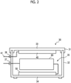
Fig. 2 is a view illustrating a state in which an electric device is accommodated in an accommodation space of the accommodation case according to the embodiment of the disclosed technology. -
Fig. 3 is a view illustrating an example of a configuration of an accommodation case stack according to the embodiment of the disclosed technology. -
Fig. 4 is a view illustrating an example of a cell culture system according to the embodiment of the disclosed technology. -
Fig. 5 is a view illustrating an example of a method of operating a microfluidic device according to the embodiment of the disclosed technology. -
Fig. 6 is a view illustrating an example of a configuration of the accommodation case stack according to the embodiment of the disclosed technology. -
Fig. 7 is a cross-sectional view illustrating an example of a configuration of an accommodation case according to another embodiment of the disclosed technology. - Hereinafter, embodiments of the present invention will be described with reference to the drawings. In each of the drawings, substantially the same or equivalent configuration elements or parts are designated by the same reference numeral.
-
Fig. 1A and Fig. 1B are respectively a perspective view and a cross-sectional view illustrating an example of a configuration of anaccommodation case 30 according to the embodiment of the disclosed technology. - The
accommodation case 30 includes alid 31 having afirst wall part 33, and amain body 32 having asecond wall part 34 facing thefirst wall part 33. Further, theaccommodation case 30 has anaccommodation space 35 that is surrounded by a plurality of wall parts including thefirst wall part 33 and thesecond wall part 34. Thefirst wall part 33 is arranged at the upper part of theaccommodation space 35, and thesecond wall part 34 is arranged at the lower part of theaccommodation space 35. Thelid 31 is provided attachably and detachably with respect to themain body 32. Thelid 31 and themain body 32 are made of, for example, an insulator such as plastic. The shape of theaccommodation case 30 is not particularly limited; however, it is typically a rectangular parallelepiped shape. - The
accommodation case 30 has a moisture-proof mechanism that suppresses the infiltration of aqueous moisture into theaccommodation space 35. Specifically, thelid 31 has agroove 31A provided along the outer edge part thereof, and the upper end portion of themain body 32 is fitted into thegroove 31A to seal theaccommodation space 35, whereby it is suppressed that aqueous moisture infiltrates the inside of theaccommodation space 35. A sealing member such as an O-ring, packing, or gasket may be provided at a portion where thelid 31 comes into contact with themain body 32 to enhance the moisture-proof function. - Further, the
accommodation case 30 includes apower supply unit 40 that is provided on thefirst wall part 33 and apower reception unit 50 that is provided on thesecond wall part 34. More specifically, thepower supply unit 40 is attached on the surface of thefirst wall part 33 on the side of theaccommodation space 35, and thepower reception unit 50 is attached on the surface of thesecond wall part 34 on the side of theaccommodation space 35. - The
power supply unit 40 is a wireless power supply unit that transmits electric power to a power supply destination in a noncontact state. As the electric power transmission method in thepower supply unit 40, a magnetic field coupling method such as an electromagnetic coupling method or a magnetic field resonance method is applied. Accordingly, thepower supply unit 40 has a configuration in which a power transmission coil (not illustrated in the drawing) is included. The wireless power supply by a magnetic field coupling method is a method of contactlessly transmitting electric power in which a power reception coil receives a magnetic field generated by a power transmission coil. As thepower supply unit 40, for example, a power supply unit having an output of about 100 kHz to several hundred kHz and 5 W to 15 W according to the Qi standard is used. As the power supply destination of thepower supply unit 40, as will be described later, a power reception unit that is provided in another accommodation case stacked on theaccommodation case 30 is considered. - The
power reception unit 50 is a wireless power reception unit that receives electric power that is supplied from a power supply source in a noncontact state. The electric power transmission method in thepower reception unit 50 is the same as that in thepower supply unit 40. Thepower reception unit 50 has a configuration in which a power reception coil (not illustrated in the drawing) that receives a magnetic field generated by a power transmission coil of a power supply source is included. As the power supply source that receives electric power supplied by thepower reception unit 50, as will described later, a power supply unit that is provided in another accommodation case arranged under theaccommodation case 30 or a power supply unit that is provided on a stage of an incubator, on which theaccommodation case 30 is placed is considered. - The
power supply unit 40 is arranged at a position spaced apart from the outer edge of thefirst wall part 33 by a predetermined distance X1. Similarly, thepower reception unit 50 is arranged at a position spaced apart from the outer edge of thesecond wall part 34 by a predetermined distance X2. The distance X1 and the distance X2 are each preferably 10 mm or more. - The
accommodation case 30 has apower supply port 36 for supplying electric power to thepower supply unit 40. In a case where thepower supply unit 40 receives electric power through thepower supply port 36 and apower supply line 41, a current flows through a power transmission coil (not illustrated in the drawing), whereby a magnetic field is generated. In addition, theaccommodation case 30 has anaccess port 37 for accessing an accommodated object that is accommodated in the inside of theaccommodation space 35. -
Fig. 2 is a view illustrating a state in which anelectric device 60 is accommodated in theaccommodation space 35 of theaccommodation case 30. Theelectric device 60 that is accommodated in theaccommodation case 30 is connected to thepower reception unit 50 and can be operated by the electric power from thepower reception unit 50. The access to theelectric device 60 that is accommodated in theaccommodation case 30 can be carried out through theaccess port 37 and anaccess line 80. -
Fig. 3 is a view illustrating an example of a configuration of anaccommodation case stack 300 according to the embodiment of the disclosed technology. Theaccommodation case stack 300 has a configuration in which a plurality ofaccommodation cases 30 are stacked. In the example illustrated inFig. 3 , theaccommodation case stack 300 having a configuration in which threeaccommodation cases 30 are stacked is exemplified; however, the number ofaccommodation cases 30 that constitute theaccommodation case stack 300 can be appropriately increased or decreased. InFig. 3 ,reference numerals - An
accommodation case 30B is stacked on anaccommodation case 30A, and anaccommodation case 30C is stacked on theaccommodation case 30B. That is, thefirst wall part 33 of theaccommodation case 30A and thesecond wall part 34 of theaccommodation case 30B are adjacent to each other, and thefirst wall part 33 of theaccommodation case 30B and thesecond wall part 34 of theaccommodation case 30C are adjacent to each other. - Since the
first wall part 33 of theaccommodation case 30A and thesecond wall part 34 of theaccommodation case 30B are adjacent to each other, thepower supply unit 40 that is provided in theaccommodation case 30A and thepower reception unit 50 that is provided in theaccommodation case 30B are adjacent to each other, and electric power can be transmitted between thepower supply unit 40 that is provided in theaccommodation case 30A and thepower reception unit 50 that is provided in theaccommodation case 30B with relatively high transmission efficiency. Theelectric device 60 that is accommodated in theaccommodation case 30B is operated by receiving electric power that is supplied from thepower reception unit 50 that is provided in theaccommodation case 30B. - Since the
first wall part 33 of theaccommodation case 30B and thesecond wall part 34 of theaccommodation case 30C are adjacent to each other, thepower supply unit 40 that is provided in theaccommodation case 30B and thepower reception unit 50 that is provided in theaccommodation case 30C are adjacent to each other, and electric power can be transmitted between thepower supply unit 40 that is provided in theaccommodation case 30B and thepower reception unit 50 that is provided in theaccommodation case 30C with relatively high transmission efficiency. Theelectric device 60 that is accommodated in theaccommodation case 30C is operated by receiving electric power that is supplied from thepower reception unit 50 that is provided in theaccommodation case 30C. - The
power reception unit 50 that is provided in theaccommodation case 30A receives electric power that is supplied from, for example, a power supply unit that is provided on the stage of the incubator in which theaccommodation case stack 300 is placed. Theelectric device 60 that is accommodated in theaccommodation case 30A is operated by receiving electric power that is supplied from thepower reception unit 50 that is provided in theaccommodation case 30A. - In the
accommodation case 30A that is arranged at the lowermost part, thepower reception unit 50 may not be provided. In this case, an operation without accommodating theelectric device 60 in theaccommodation case 30A is considered. Further, in theaccommodation case 30C that is arranged at the uppermost part, thepower supply unit 40 may not be provided. -
Fig. 4 is a view illustrating an example of a configuration of acell culture system 100, in which amicrofluidic device 110 is included. Thecell culture system 100 has a configuration in which themicrofluidic device 110, astorage container 120, apump 121, aflow rate sensor 122, animpedance measuring instrument 124, awaste liquid container 123, asystem control unit 125, and apipe 130 are included. - The
microfluidic device 110 has amicro flow channel 111 that is formed by using a microfabrication technology such as MEMS technology, aninflow port 112 that is provided at one end of themicro flow channel 111, and anoutflow port 113 that is provided at the other end of themicro flow channel 111. Further, themicrofluidic device 110 has anelectrode 114 that is provided in the middle of themicro flow channel 111. In cell culture using thecell culture system 100, cells are arranged inside themicro flow channel 111, and then the cells are cultured. - The
storage container 120 is connected to theinflow port 112 through thepipe 130. Thepump 121 and theflow rate sensor 122 are provided in the middle of thepipe 130. Thestorage container 120 stores a liquid such as a medium, additives, and reagents, which is used for culturing cells accommodated in themicrofluidic device 110. Thecell culture system 100 may have a plurality of storage containers respectively storing a plurality of different kinds of liquids or may have a configuration such that liquids accommodated inside a plurality of storage containers can be selectively supplied to themicrofluidic device 110. - The
pump 121 carries out feeding of a liquid such as a medium stored in thestorage container 120. In a case where thepump 121 is driven, the liquid accommodated in thestorage container 120 is supplied to themicro flow channel 111 through theinflow port 112. Theflow rate sensor 122 detects the flow rate of the liquid supplied to themicrofluidic device 110 per unit time and outputs a detection signal indicating the detected flow rate. The liquid supplied to themicro flow channel 111 flows out from theoutflow port 113 and is collected in thewaste liquid container 123 through thepipe 130. - The
impedance measuring instrument 124 is connected to theelectrode 114 that is provided in the middle of themicro flow channel 111 and outputs an impedance value depending on the state of cells that are cultured on themicro flow channel 111 based on an electric signal supplied from theelectrode 114. The above impedance value may correspond to, for example, a transepithelial electrical resistance value. - The
system control unit 125 controls the drive of thepump 121 based on the detection signal output from theflow rate sensor 122. That is, thesystem control unit 125 controls the feeding amount of liquid in thepump 121 so that the flow rate of the liquid per unit time, which is indicated by the detection signal output from theflow rate sensor 122, becomes a predetermined value. Further, thesystem control unit 125 carries out control for recording the impedance value measured by theimpedance measuring instrument 124 and transmitting it to the external system. - The electric device including the
pump 121, theflow rate sensor 122, theimpedance measuring instrument 124, and thesystem control unit 125 is operated by receiving electric power that is supplied from thepower reception unit 50. -
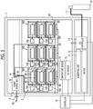
Fig. 5 is a view illustrating an example of a method of operating themicrofluidic device 110. A plurality ofcell culture systems 100 each including themicrofluidic device 110 are accommodated inside anaccommodation space 2 of an incubator 1. - The incubator 1 has the
accommodation space 2 shielded from the external environment. The incubator 1 has acontroller 10, ahumidifying unit 11, aheater 12, a CO2 controller 13, atemperature sensor 14, and a CO2 sensor 15 as environmental control units for controlling the environment of theaccommodation space 2. - The
temperature sensor 14 is provided inside theaccommodation space 2, detects the temperature in theaccommodation space 2, and supplies a detection signal indicating the detected temperature to thecontroller 10. The CO2 sensor 15 is provided inside theaccommodation space 2, detects the CO2 concentration in theaccommodation space 2, and supplies a detection signal indicating the detected CO2 concentration to thecontroller 10. - The
controller 10 controls theheater 12 so that the temperature in theaccommodation space 2 becomes the temperature specified by a user, based on the temperature detected by thetemperature sensor 14. Further, thecontroller 10 controls the CO2 controller 13 so that the CO2 concentration in theaccommodation space 2 becomes the concentration specified by a user, based on the CO2 concentration detected by the CO2 sensor 15. The CO2 controller 13 is connected to a CO2 cylinder 16, which is installed outside the incubator 1, through apipe 17, and adjusts the amount of CO2 gas that is released into the inside of theaccommodation space 2 based on the control by thecontroller 10, where the CO2 gas is supplied from the CO2 cylinder 16. - The
humidifying unit 11 has a configuration in which a vat in which water is stored is included, and the humidity in theaccommodation space 2 is maintained above a predetermined value due to the spontaneous vaporization of the water in the vat. - A
stage 20 is provided in theaccommodation space 2. A plurality ofpower supply units 45 are provided on thestage 20. As each of thepower supply units 45, the power supply unit the same as thepower supply unit 40 that is provided in theaccommodation case 30 is used. - On the
stage 20, the accommodation case stacks 300 are arranged at positions matching with the respectivepower supply units 45. In the example illustrated inFig. 5 , each of thecell culture systems 100 corresponds to each of theaccommodation cases 30. That is, onecell culture system 100 is disposed for oneaccommodation case 30. Each of theaccommodation cases 30 constituting theaccommodation case stack 300 accommodates theelectric device 60 that includes a part or all of thepump 121, theflow rate sensor 122, theimpedance measuring instrument 124, and thesystem control unit 125, among the configuration elements of the correspondingcell culture system 100. Themicrofluidic device 110 is connected to theelectric device 60 that is accommodated in thecorresponding accommodation case 30 through the access port 37 (seeFig. 3 ) and theaccess line 80. Thestorage container 120 and thewaste liquid container 123, which are not illustrated inFig. 5 , are arranged outside theaccommodation case 30 together with themicrofluidic device 110. - Each of the
power supply units 40 accommodated in theaccommodation case 30 and each of thepower supply units 45 provided on thestage 20 are connected to thepower source unit 70 through thepower supply line 41, and electric power is supplied from thepower source unit 70, whereby a current flows to the power transmission coil (not illustrated in the drawing) to generate a magnetic field. In the example illustrated inFig. 5 , thepower supply line 41 is not connected to thepower supply units 40 that are provided in theaccommodation case 30 at the uppermost part of theaccommodation case stack 300, and thus electric power is not supplied to thesepower supply units 40. - The
power source unit 70 is arranged in a shieldedspace 4 that is shielded from theaccommodation space 2. The humidity in the shieldedspace 4 is set to be the same level as that of the humidity outside the incubator 1 and is lower than the humidity in theaccommodation space 2 that is maintained at a relatively high humidity. Since thepower source unit 70 is arranged in the shieldedspace 4, thepower source unit 70 is prevented from being exposed to a high humidity environment, and the occurrence of problems such as electric leakage is suppressed. Thepower supply line 42 for supplying electric power to thepower source unit 70 is led out to the outside of the incubator 1 through thepower supply port 3 that is provided on the wall surface of the incubator 1. Here, in a case where the number of power supply lines that are led out to the outside of the incubator 1 is increased, the risk of foreign matters such as dust and bacteria being mixed into the inside of theaccommodation space 2 of the incubator 1 increases. In a case where electric power is distributed from thepower source unit 70 accommodated inside the incubator 1 to a plurality ofpower supply units 40 andpower supply units 41 through thepower supply line 41, the number of power supply lines that are led out to the outside of the incubator 1 can be reduced to one, and thus the risk of the inside of theaccommodation space 2 being contaminated can be suppressed. - The
power reception unit 50 that is provided in theaccommodation case 30A arranged at the lowermost part of theaccommodation case stack 300 receives electric power that is supplied from thepower supply unit 45 that is provided on thestage 20. In a case where theelectric device 60 that is accommodated in theaccommodation case 30A arranged at the lowermost part of theaccommodation case stack 300 is operated by receiving electric power that is supplied from thepower reception unit 50 that is provided in theaccommodation case 30A, whereby the aboveelectric device 60 connected to themicrofluidic device 110 is operated. - The
power reception unit 50 that is provided in theaccommodation case 30B stacked on theaccommodation case 30A receives electric power that is supplied from thepower supply unit 40 that is provided in theaccommodation case 30A. In a case where theelectric device 60 that is accommodated in theaccommodation case 30B is operated by receiving electric power that is supplied from thepower reception unit 50 that is provided in theaccommodation case 30B, whereby the aboveelectric device 60 connected to themicrofluidic device 110 is operated. - The
power reception unit 50 that is provided in theaccommodation case 30C stacked on theaccommodation case 30B receives electric power that is supplied from thepower supply unit 40 that is provided in theaccommodation case 30B. In a case where theelectric device 60 that is accommodated in theaccommodation case 30C is operated by receiving electric power that is supplied from thepower reception unit 50 that is provided in theaccommodation case 30C, whereby the aboveelectric device 60 connected to themicrofluidic device 110 is operated. - As described above, the first aspect of the method of operating the
microfluidic device 110 according to the embodiment of the disclosed technology is realized by using theaccommodation case 30. That is, the method of operating themicrofluidic device 110 include accommodating theelectric device 60 that is operated by receiving electric power that is supplied from thepower reception unit 50, in theaccommodation space 35 of theaccommodation case 30, connecting themicrofluidic device 110 to theelectric device 60, and arranging the accommodation case in which theelectric device 60 is accommodated and themicrofluidic device 110 inside the incubator 1, to operate themicrofluidic device 110. - In addition, the second aspect of the method of operating the
microfluidic device 110 according to the embodiment of the disclosed technology is realized by using theaccommodation case stack 300. That is, the method of operating themicrofluidic device 110 includes accommodating a firstelectric device 60 that is operated by receiving electric power that is supplied from thepower reception unit 50 that is provided in afirst accommodation case 30, in theaccommodation space 35 of thefirst accommodation case 30, accommodating a secondelectric device 60 that is operated by receiving electric power that is supplied from thepower reception unit 50 that is provided in thesecond accommodation case 30, in theaccommodation space 35 of the second accommodation case that is stacked on thefirst accommodation case 30, connecting the firstmicrofluidic device 110 to the firstelectric device 60, connecting the secondmicrofluidic device 110 to the secondelectric device 60, and arranging thefirst accommodation case 30 in which the firstelectric device 60 is accommodated, thesecond accommodation case 30 in which the secondelectric device 60 is accommodated, the firstmicrofluidic device 110, and the secondmicrofluidic device 110 inside the incubator 1, to operate the firstmicrofluidic device 110 and the secondmicrofluidic device 110. - According to the method of operating the
accommodation case 30, theaccommodation case stack 300, and themicrofluidic device 110, according to the embodiment of the disclosed technology, electric power can be transmitted between the upper and lower accommodation cases adjacent to each other since a plurality ofaccommodation cases 30 are stacked. As a result, the degree of freedom in arranging thepower reception unit 50 in the incubator 1 can be increased as compared with the case where the power supply unit is provided only in thestage 20 of the incubator 1. Therefore, it is possible to ensure a degree of freedom in arranging theelectric devices 60 such as the sensor and the pump that are operated by receiving electric power that is supplied from thepower reception unit 50. - Further, since the
electric device 60 such as the sensor and the pump is accommodated in theaccommodation case 30, theelectric device 60 is not exposed to a high humidity environment in the incubator 1, and thus it is possible to suppress the risk of damaging electric devices due to moisture. In a case where theaccommodation case 30 has a moisture-proof mechanism for preventing infiltration of aqueous moisture into the inside of theaccommodation space 35, it is possible to enhance the effect of suppressing the risk of damage. - In addition, the
power supply unit 40 is arranged at a position spaced apart from the outer edge of thefirst wall part 33, and thepower reception unit 50 is arranged at a position spaced apart from the outer edge of thesecond wall part 34. As a result, as illustrated inFig. 5 , in a case where a plurality of accommodation case stacks 300 are arranged side by side on thestage 20, it is possible to ensure, in the plane direction, the distance between apower supply unit 40 that constitutes a certainaccommodation case stack 300 and apower supply unit 40 that constitutes another adjacentaccommodation case stack 300 and the distance between apower reception unit 50 that constitutes a certainaccommodation case stack 300 and apower reception unit 50 that constitutes another adjacentaccommodation case stack 300. As a result, it is possible to reduce the influence of the electromagnetic waves radiated from thepower supply unit 40 and thepower reception unit 50 on another power supply unit or power reception unit that is adjacent to thepower supply unit 40 and thepower reception unit 50 in the plane direction. - In the above embodiment, the case where each of the
cell culture systems 100 is provided to correspond to each of theaccommodation cases 30 is illustrated; however, the present invention is not limited to this aspect. That is, a plurality of electric devices constituting onecell culture system 100 may be dispersedly accommodated in a plurality ofaccommodation cases 30. In this case, in a case where a part or all of the plurality of electric devices dispersedly accommodated in the plurality ofaccommodation cases 30 are connected to themicrofluidic device 110, themicrofluidic device 110 is operated. - Further, in the above embodiment, a case where the
power reception unit 50 is provided in theaccommodation case 30A that is arranged at the lowermost part of theaccommodation case stack 300, and the electric power supply to thepower reception unit 50 is carried out by thepower supply unit 45 that is provided on thestage 20; however, the present invention is not limited to this aspect. For example, thepower supply unit 45 may not be provided on thestage 20. In this case, thepower reception unit 50 may not be provided in theaccommodation case 30A that is arranged at the lowermost part of theaccommodation case stack 300, or theelectric device 60 may not be accommodated in theaccommodation case 30A. Further, in theaccommodation case 30C that is arranged at the uppermost part of theaccommodation case stack 300, thepower supply unit 40 may not be provided. - Further, as illustrated in
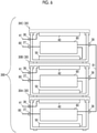
Fig. 6 , theelectric devices 60 that are accommodated in theaccommodation cases 30 constituting theaccommodation case stack 300 may be configured to communicate with each other through acommunication port 38 and acommunication line 81 that are provided in each of theaccommodation cases 30. -
Fig. 7 is a cross-sectional view illustrating an example of a configuration of theaccommodation case 30A according to the second embodiment of the disclosed technology. In theaccommodation case 30A, awall part 39 surrounding theaccommodation space 35 has a shieldingpart 90 that shields electromagnetic waves radiated from thepower supply unit 40 and thepower reception unit 50. The shieldingpart 90 can be made of, for example, a conductive film that covers the inner surface of thewall part 39. As the material of the conductive film, a metal such as aluminum, copper, or stainless steel can be used. - As described above, since the
accommodation case 30A has the shieldingpart 90, it is possible to suppress the leakage of electromagnetic waves radiated from thepower supply unit 40 and thepower reception unit 50 to the outside of theaccommodation case 30A. This makes it possible to suppress a risk that the electric device that is provided outside theaccommodation case 30A malfunctions due to the electromagnetic waves radiated from thepower supply unit 40 and thepower reception unit 50. - The
accommodation case stack 300 may have a configuration in which theaccommodation case 30A according to the present embodiment is included. In addition, theelectric device 60 that is operated by receiving electric power that is supplied from thepower reception unit 50 may be accommodated in theaccommodation space 35 of theaccommodation case 30A according to the present embodiment, themicrofluidic device 110 may be connected to theelectric device 60, and theaccommodation case 30A in which theelectric device 60 is accommodated and themicrofluidic device 110 may be arranged inside the incubator 1, to operate themicrofluidic device 110. - The disclosure of
JP2019-044497 filed on March 12, 2019
Claims (10)
- An accommodation case comprising:a first wall part in which a power supply unit that transmits electric power to a power supply destination in a noncontact state is provided;a second wall part in which a power reception unit that receives electric power that is supplied from a power supply source in a noncontact state is provided, the second wall part facing the first wall part; andan accommodation space that is surrounded by a plurality of wall parts including the first wall part and the second wall part.
- The accommodation case according to claim 1, further comprising:
a moisture-proof mechanism for preventing infiltration of aqueous moisture into the accommodation space. - The accommodation case according to claim 1 or 2,wherein the first wall part is arranged in an upper part of the accommodation space, andthe second wall part is arranged in a lower part of the accommodation space.
- The accommodation case according to any one of claims 1 to 3,wherein the power supply unit is arranged at a position spaced apart from an outer edge of the first wall part, andthe power reception unit is arranged at a position spaced apart from an outer edge of the second wall part.
- The accommodation case according to any one of claims 1 to 3,
wherein at least one of the plurality of wall parts has a shielding part that shields electromagnetic waves radiated from the power supply unit and the power reception unit. - The accommodation case according to any one of claims 1 to 4, further comprising:
an access port for accessing an accommodated object that is accommodated in the accommodation space. - An accommodation case stack in which a first accommodation case and a second accommodation case are stacked, in which each of the first accommodation case and the second accommodation case has;a first wall part in which a power supply unit that transmits electric power to a power supply destination in a noncontact state is provided,a second wall part in which a power reception unit that receives electric power that is supplied from a power supply source in a noncontact state is provided, the second wall part facing the first wall part, andan accommodation space that is surrounded by a plurality of wall parts including the first wall part and the second wall part,wherein the first wall part of the first accommodation case and the second wall part of the second accommodation case are adjacent to each other.
- A method of operating a microfluidic device, which uses the accommodation case according to any one of claims 1 to 6, the method comprising:accommodating an electric device that is operated by receiving electric power that is supplied from the power reception unit, in the accommodation space of the accommodation case;connecting the microfluidic device to the electric device; andarranging the accommodation case in which the electric device is accommodated and the microfluidic device in an incubator to operate the microfluidic device.
- A method of operating a microfluidic device, which uses the accommodation case stack according to claim 7, the method comprising:accommodating a first electric device that is operated by receiving electric power that is supplied from the power reception unit that is provided on the second wall part of the first accommodation case, in the accommodation space of the first accommodation case;accommodating a second electric device that is operated by receiving electric power that is supplied from the power reception unit that is provided on the second wall part of the second accommodation case, in the accommodation space of the second accommodation case;connecting a first microfluidic device to the first electric device;connecting a second microfluidic device to the second electric device; andarranging the first accommodation case in which the first electric device is accommodated, the second accommodation case in which the second electric device is accommodated, the first microfluidic device, and the second microfluidic device in an incubator to operate the first microfluidic device and the second microfluidic device.
- The method of operating a microfluidic device according to claim 9,
wherein the first electric device communicates with the second electric device.
Applications Claiming Priority (2)
| Application Number | Priority Date | Filing Date | Title |
|---|---|---|---|
| JP2019044497 | 2019-03-12 | ||
| PCT/JP2020/002932 WO2020183949A1 (en) | 2019-03-12 | 2020-01-28 | Accommodation case, accommodation case stack, and method for operating microfluidic device |
Publications (2)
| Publication Number | Publication Date |
|---|---|
| EP3940389A1 true EP3940389A1 (en) | 2022-01-19 |
| EP3940389A4 EP3940389A4 (en) | 2022-04-27 |
Family
ID=72426722
Family Applications (1)
| Application Number | Title | Priority Date | Filing Date |
|---|---|---|---|
| EP20769994.3A Pending EP3940389A4 (en) | 2019-03-12 | 2020-01-28 | Accommodation case, accommodation case stack, and method for operating microfluidic device |
Country Status (4)
| Country | Link |
|---|---|
| US (1) | US12312577B2 (en) |
| EP (1) | EP3940389A4 (en) |
| JP (1) | JP7187669B2 (en) |
| WO (1) | WO2020183949A1 (en) |
Families Citing this family (1)
| Publication number | Priority date | Publication date | Assignee | Title |
|---|---|---|---|---|
| US12342514B1 (en) * | 2021-02-17 | 2025-06-24 | Geoffrey Alden Wilsey | Cellular electromagnetic field containment, charging, and sanitizing device |
Family Cites Families (22)
| Publication number | Priority date | Publication date | Assignee | Title |
|---|---|---|---|---|
| US20020114739A1 (en) * | 2000-12-26 | 2002-08-22 | Weigl Bernard H. | Microfluidic cartridge with integrated electronics |
| US20070236174A1 (en) * | 2006-04-09 | 2007-10-11 | Evan John Kaye | Point-Of-Sale Non-Contact Charging |
| JP2009111557A (en) * | 2007-10-29 | 2009-05-21 | Mitsubishi Electric Corp | Information input / output device, electronic equipment, induction heating cooker, heating cooker, refrigerator, washing machine, rice cooker |
| US8466583B2 (en) * | 2008-09-27 | 2013-06-18 | Witricity Corporation | Tunable wireless energy transfer for outdoor lighting applications |
| US20110127175A1 (en) * | 2009-11-30 | 2011-06-02 | Roche Diagnostics Operations, Inc. | Test strip container with expandable insert and methods of manufacturing and utilization thereof |
| WO2012064896A2 (en) * | 2010-11-09 | 2012-05-18 | The Regents Of The University Of California | Wireless power mechanisms for lab-on-a-chip devices |
| US10141770B2 (en) * | 2011-01-18 | 2018-11-27 | Mojo Mobility, Inc. | Powering and/or charging with a plurality of protocols |
| WO2013027761A1 (en) | 2011-08-22 | 2013-02-28 | 積水化学工業株式会社 | Reefer container and system for supplying power to reefer container |
| JP5755560B2 (en) * | 2011-12-21 | 2015-07-29 | ニチコン株式会社 | Wireless power supply apparatus and wireless power supply system |
| JP2013228220A (en) * | 2012-04-24 | 2013-11-07 | Nissha Printing Co Ltd | Micro fluid chip |
| JP6149499B2 (en) * | 2013-05-14 | 2017-06-21 | 株式会社Ihi | Contactless power supply system |
| JPWO2016043135A1 (en) | 2014-09-19 | 2017-07-06 | 日本電気株式会社 | Charging device, charging system, and electronic device |
| US9837862B2 (en) * | 2014-10-16 | 2017-12-05 | DePuy Synthes Products, Inc. | Inductively-powered surgical instrument system |
| KR101663191B1 (en) * | 2015-01-30 | 2016-10-07 | 한솔테크닉스(주) | Humidification apparatus of radio charge base |
| KR102314319B1 (en) * | 2016-01-04 | 2021-10-20 | 엘지전자 주식회사 | refrigerator |
| JP2017169365A (en) * | 2016-03-16 | 2017-09-21 | アルプス電気株式会社 | Detection unit for cultivation container, container, and non-contact power transmission system |
| JP6540895B2 (en) * | 2016-05-31 | 2019-07-10 | 三菱電機株式会社 | Cold storage device |
| JP2018153024A (en) | 2017-03-14 | 2018-09-27 | オムロンオートモーティブエレクトロニクス株式会社 | Power transmission equipment |
| JP2018201290A (en) * | 2017-05-26 | 2018-12-20 | Tdk株式会社 | Non-contact power transmission device |
| CN111803084A (en) | 2017-06-02 | 2020-10-23 | 西北大学 | Microfluidic systems for epidermal sampling and sensing |
| JP2019044497A (en) | 2017-09-04 | 2019-03-22 | 大崎工業株式会社 | Sign sheet, sign sheet manufacturing method, sign body sheet, sign body sheet manufacturing method, and sign body installation method |
| US10806816B2 (en) * | 2018-05-15 | 2020-10-20 | The Procter & Gamble Company | Microfluidic cartridge and microfluidic delivery device comprising the same |
-
2020
- 2020-01-28 JP JP2021505574A patent/JP7187669B2/en active Active
- 2020-01-28 EP EP20769994.3A patent/EP3940389A4/en active Pending
- 2020-01-28 WO PCT/JP2020/002932 patent/WO2020183949A1/en not_active Ceased
-
2021
- 2021-08-31 US US17/462,024 patent/US12312577B2/en active Active
Also Published As
| Publication number | Publication date |
|---|---|
| US20210395673A1 (en) | 2021-12-23 |
| EP3940389A4 (en) | 2022-04-27 |
| JPWO2020183949A1 (en) | 2020-09-17 |
| WO2020183949A1 (en) | 2020-09-17 |
| JP7187669B2 (en) | 2022-12-12 |
| US12312577B2 (en) | 2025-05-27 |
Similar Documents
| Publication | Publication Date | Title |
|---|---|---|
| US10890596B2 (en) | Sampling probes, systems, apparatuses, and methods | |
| EP3216228B1 (en) | Disposable multivariable sensing devices having radio frequency based sensors | |
| CN101370537B (en) | Pressure measurement unit for determining fluid pressure within medical disposables | |
| US12312577B2 (en) | Accommodation case, accommodation case stack, and method of operating microfluidic device | |
| US10736463B2 (en) | Multiport/rotary valve sensor using hall effect control | |
| JP6120240B2 (en) | Non-contact power transmission device for sealed space | |
| US20130238145A1 (en) | Sensor system | |
| US10955307B2 (en) | Inline sensor and fluid line system | |
| CN102778575A (en) | Analytical device for automated determining of a measured variable of a measured liquid | |
| US12306155B2 (en) | Devices, systems and methods for detecting, measuring and monitoring chemicals or characteristics of substances | |
| US12325845B2 (en) | Incubator and method of operating microfluidic device | |
| JP2017169365A (en) | Detection unit for cultivation container, container, and non-contact power transmission system | |
| US20260062663A1 (en) | Submersible Sensor Capsule and System | |
| CN214333949U (en) | A liquid level detection device and liquid supply device | |
| CN112013888B (en) | Submersible pump assembly and method for operating a submersible pump assembly | |
| EP1893995B1 (en) | Measurement instrument | |
| JP2017100453A (en) | Ink jet recording device | |
| EP3457370B1 (en) | Operating and information transmitting system for actuating and sensing module | |
| JP2025168411A (en) | Acquisition device and information collection system | |
| WO2020183098A3 (en) | Machine for distributing a liquid or paste-type product, and method for operational control of said machine | |
| US20200140803A1 (en) | Cell incubator and a tool for use in a cell incubator | |
| NZ736739A (en) | Filter including rfid tag |
Legal Events
| Date | Code | Title | Description |
|---|---|---|---|
| STAA | Information on the status of an ep patent application or granted ep patent |
Free format text: STATUS: THE INTERNATIONAL PUBLICATION HAS BEEN MADE |
|
| PUAI | Public reference made under article 153(3) epc to a published international application that has entered the european phase |
Free format text: ORIGINAL CODE: 0009012 |
|
| STAA | Information on the status of an ep patent application or granted ep patent |
Free format text: STATUS: REQUEST FOR EXAMINATION WAS MADE |
|
| 17P | Request for examination filed |
Effective date: 20210910 |
|
| AK | Designated contracting states |
Kind code of ref document: A1 Designated state(s): AL AT BE BG CH CY CZ DE DK EE ES FI FR GB GR HR HU IE IS IT LI LT LU LV MC MK MT NL NO PL PT RO RS SE SI SK SM TR |
|
| A4 | Supplementary search report drawn up and despatched |
Effective date: 20220324 |
|
| RIC1 | Information provided on ipc code assigned before grant |
Ipc: G01N 35/00 20060101ALN20220319BHEP Ipc: B01L 3/00 20060101ALI20220319BHEP Ipc: H02J 50/50 20160101ALI20220319BHEP Ipc: C12M 3/06 20060101ALI20220319BHEP Ipc: B01L 9/00 20060101ALI20220319BHEP Ipc: C12M 1/00 20060101ALI20220319BHEP Ipc: B01L 1/02 20060101ALI20220319BHEP Ipc: H02J 50/00 20160101ALI20220319BHEP Ipc: H02J 50/10 20160101ALI20220319BHEP Ipc: G01N 35/08 20060101AFI20220319BHEP |
|
| DAV | Request for validation of the european patent (deleted) | ||
| DAX | Request for extension of the european patent (deleted) |