EP3940350A1 - Weight-measuring device - Google Patents
Weight-measuring device Download PDFInfo
- Publication number
- EP3940350A1 EP3940350A1 EP20770516.1A EP20770516A EP3940350A1 EP 3940350 A1 EP3940350 A1 EP 3940350A1 EP 20770516 A EP20770516 A EP 20770516A EP 3940350 A1 EP3940350 A1 EP 3940350A1
- Authority
- EP
- European Patent Office
- Prior art keywords
- cover
- surface cover
- receiving member
- weight
- bridge
- Prior art date
- Legal status (The legal status is an assumption and is not a legal conclusion. Google has not performed a legal analysis and makes no representation as to the accuracy of the status listed.)
- Granted
Links
Images





Classifications
-
- G—PHYSICS
- G01—MEASURING; TESTING
- G01G—WEIGHING
- G01G3/00—Weighing apparatus characterised by the use of elastically-deformable members, e.g. spring balances
- G01G3/12—Weighing apparatus characterised by the use of elastically-deformable members, e.g. spring balances wherein the weighing element is in the form of a solid body stressed by pressure or tension during weighing
- G01G3/14—Weighing apparatus characterised by the use of elastically-deformable members, e.g. spring balances wherein the weighing element is in the form of a solid body stressed by pressure or tension during weighing measuring variations of electrical resistance
-
- A—HUMAN NECESSITIES
- A61—MEDICAL OR VETERINARY SCIENCE; HYGIENE
- A61B—DIAGNOSIS; SURGERY; IDENTIFICATION
- A61B5/00—Measuring for diagnostic purposes; Identification of persons
- A61B5/103—Measuring devices for testing the shape, pattern, colour, size or movement of the body or parts thereof, for diagnostic purposes
- A61B5/1036—Measuring load distribution, e.g. podologic studies
-
- G—PHYSICS
- G01—MEASURING; TESTING
- G01G—WEIGHING
- G01G21/00—Details of weighing apparatus
- G01G21/02—Arrangements of bearings
- G01G21/10—Floating suspensions; Arrangements of shock absorbers
-
- G—PHYSICS
- G01—MEASURING; TESTING
- G01G—WEIGHING
- G01G21/00—Details of weighing apparatus
- G01G21/22—Weigh pans or other weighing receptacles; Weighing platforms
-
- G—PHYSICS
- G01—MEASURING; TESTING
- G01G—WEIGHING
- G01G21/00—Details of weighing apparatus
- G01G21/23—Support or suspension of weighing platforms
-
- G—PHYSICS
- G01—MEASURING; TESTING
- G01L—MEASURING FORCE, STRESS, TORQUE, WORK, MECHANICAL POWER, MECHANICAL EFFICIENCY, OR FLUID PRESSURE
- G01L1/00—Measuring force or stress, in general
- G01L1/26—Auxiliary measures taken, or devices used, in connection with the measurement of force, e.g. for preventing influence of transverse components of force, for preventing overload
-
- A—HUMAN NECESSITIES
- A61—MEDICAL OR VETERINARY SCIENCE; HYGIENE
- A61B—DIAGNOSIS; SURGERY; IDENTIFICATION
- A61B2562/00—Details of sensors; Constructional details of sensor housings or probes; Accessories for sensors
- A61B2562/02—Details of sensors specially adapted for in-vivo measurements
- A61B2562/0252—Load cells
-
- A—HUMAN NECESSITIES
- A61—MEDICAL OR VETERINARY SCIENCE; HYGIENE
- A61B—DIAGNOSIS; SURGERY; IDENTIFICATION
- A61B2562/00—Details of sensors; Constructional details of sensor housings or probes; Accessories for sensors
- A61B2562/02—Details of sensors specially adapted for in-vivo measurements
- A61B2562/0261—Strain gauges
-
- A—HUMAN NECESSITIES
- A61—MEDICAL OR VETERINARY SCIENCE; HYGIENE
- A61B—DIAGNOSIS; SURGERY; IDENTIFICATION
- A61B5/00—Measuring for diagnostic purposes; Identification of persons
- A61B5/05—Detecting, measuring or recording for diagnosis by means of electric currents or magnetic fields; Measuring using microwaves or radio waves
- A61B5/053—Measuring electrical impedance or conductance of a portion of the body
- A61B5/0537—Measuring body composition by impedance, e.g. tissue hydration or fat content
-
- G—PHYSICS
- G01—MEASURING; TESTING
- G01G—WEIGHING
- G01G19/00—Weighing apparatus or methods adapted for special purposes not provided for in the preceding groups
- G01G19/44—Weighing apparatus or methods adapted for special purposes not provided for in the preceding groups for weighing persons
Definitions
- the present invention relates to a weight measurement device for measuring the weight of a measurement target.
- a weight measurement device for measuring the weight of a measurement target such as a human body.
- a weight measurement device has at least one load cell (normally four in the case of a weight scale) to which the weight of a measurement target is transferred.
- a load cell has a strain generating body to deform when the weight of the measurement target is transferred thereto, and a strain gauge for generating a signal corresponding to the deformation of the strain generating body. Based on the signal output from the strain gauge described above, a processing circuitry on a board calculates the weight of the measurement target.
- a weight measurement device 200 as shown in FIG. 19 which is designed so that when a measurement target is placed on an upper surface cover 202 while a rubber 208 is sandwiched between a bridge 223 and a leg 210, a weight (upward force) from the leg 210 is transferred to (movable arm parts of) a load cell 205 through the rubber 208 and the bridge 223 (refer for example to Patent Document 1).
- a member 242 in FIG. 19 is a boss (a member equivalent to the boss 42 in FIG. 2 described later) integrally formed with the bride 223, and serves as a spacer to keep the distance between a lower surface 205a of the load cell 205 and an upper surface 223a of the bridge 223.
- this weight measurement device 200 As shown on the right side of FIG. 19 , when the upper surface cover 202 and a housing 203 are loaded with the weight of the measurement target, the load cell 205 inclines as the upper surface cover 202 and the housing 203 deflect due to the weight. Corresponding to this inclination, the rubber 208 is a little compressed while deforming in a horizontal direction, causing the upper surface of the rubber 208 to incline, whereby the bridge 223 inclines corresponding to the inclination of the load cell 205, making it possible to keep the upper surface 223a of the bridge 223 to be in parallel to the lower surface 205a of the load cell 205.
- the upper surface 223a of the bridge 223 can be kept in parallel to the lower surface 205a of the load cell 205, and therefore, upward force in the vertical direction can be stably applied to (the movable arm parts of) the load cell 205 from the bridge 223. Therefore, regardless of the manner of deflection of the upper surface cover 202 and the housing 203, an accurate output from (the strain gauge of) the load cell 205 can be obtained, thus making it possible to accurately measure the weight of the measurement target.
- Patent Document 1 Japanese Laid-open Patent Publication 2014-66572
- the rubber 208 is sandwiched between the bridge 223 and the leg 210, and this rubber 208 is used to keep the upper surface 223a of the bridge 223 to be in parallel to the lower surface 205a of the load cell 205 as in the conventional weight measurement device 200 described above, the rubber 208 is required to be some sufficiently thick rubber (for example, 5 mm), causing the problem that it is not possible to achieve reduction in the thickness of the entire device.
- An object of the present invention is to solve the problems described above and to provide a weight measurement device which can obtain an accurate output from a load cell, and can accurately measure the weight of the measurement target, regardless of the manner of deflection of an upper surface cover and so on, and which can achieve reduction in the thickness of the entire device.
- a weight measurement device comprises: an upper surface cover on which a measurement target is placed; a load cell to detect weight of the measurement target placed on the upper surface cover; a bridge to support the load cell; a receiving member to receive the weight of the measurement target placed on the upper surface cover; and a bottom surface cover provided on a lower surface side of the receiving member, wherein the weight measurement device further comprises a sliding part provided between the lower surface of the receiving member and an upper surface of the bottom surface cover to enable the receiving member to move in a horizontal direction relative to the bottom cover, and wherein the bridge comprises a pivot which is a fulcrum to make it possible to change inclination of the bridge relative to the bottom surface cover and is in contact with an upper surface of the receiving member.
- friction coefficient of the sliding part is set to satisfy the relationship that when the upper surface cover deflects due to the weight of the measurement target placed on the upper surface cover, friction force generated between the receiving member and the bottom surface cover is smaller than friction force generated between the pivot and the receiving member.
- the sliding part can be a sheet made of resin pasted on at least one of the lower surface of the receiving member and the upper surface of the bottom surface cover.
- the sheet made of resin can be a sheet made of fluorocarbon resin.
- the sliding part can be resin coated on at least one of the lower surface of the receiving member and the upper surface of the bottom surface cover.
- the coated resin can be fluorocarbon resin.
- the sliding part can be at least one of the lower surface of the receiving member and the upper surface of the bottom surface cover having been subjected to plating treatment.
- the receiving member can comprise: a plate-shaped part in contact with the pivot; an elastic part provided on an outer periphery of the plate-shaped part; and an outer frame part provided on an outer periphery of the elastic part, wherein only the outer frame part can be attached to the bottom surface cover without attaching the plate-shaped part and the elastic part to the bottom surface cover.
- this weight measurement device can further comprise a leaf spring to attach the bridge to the bottom surface cover side, wherein the leaf spring can have a peripheral part fixed to the bottom surface cover, and is formed to be elastically deformable.
- the leaf spring can be connected to the upper surface cover side, wherein the weight measurement device can further comprise a separation prevention member to prevent the bottom surface cover from being separated from the upper surface cover by a given distance or more, and wherein the given distance can be a distance to prevent the leaf spring fixed to the bottom surface cover side from being stretched to its limit.
- this weight measurement device can further comprise a reinforcement cover connected to the upper surface cover, wherein the reinforcement cover can comprise an upper surface cover made of metal, a bottom surface cover made of metal, and a resin layer provided between the upper surface cover made of metal and the bottom surface cover made of metal, wherein many fine recessed parts can be formed in a lower surface of the upper surface cover made of metal and an upper surface of the bottom surface cover made of metal, and wherein resin of the resin layer can be filled into the many fine recessed parts so as to bond the upper surface cover made of metal, the resin layer and the bottom surface cover made of metal.
- the reinforcement cover can comprise an upper surface cover made of metal, a bottom surface cover made of metal, and a resin layer provided between the upper surface cover made of metal and the bottom surface cover made of metal, wherein many fine recessed parts can be formed in a lower surface of the upper surface cover made of metal and an upper surface of the bottom surface cover made of metal, and wherein resin of the resin layer can be filled into the many fine recessed parts so as to bond the upper surface cover made of
- the pivot becomes unable to move in a horizontal direction relative to the receiving member due to the friction force generated between the pivot of the bridge and the upper surface of the receiving member when the upper surface cover deflects due to the weight of a measurement target, it is possible to move the receiving member in a horizontal direction relative to the bottom surface cover due to the function of the sliding part provided between the lower surface of the receiving member and the upper surface of the bottom surface cover. Therefore, the inclination of the bridge relative to the bottom surface cover can be changed by moving the pivot in a horizontal direction relative to the bottom surface cover.
- the weight measurement device of the present invention is a body composition meter.
- FIG. 1 is an exploded perspective view of the entire body composition meter according to the present embodiment.
- the body composition meter 1 has a function to measure the weight of a subject, and a function to measure the body composition of the subject such as body fat rate, amount of muscle, estimated amount of bone, visceral fat level, amount of basal metabolism, body water rate and so on.
- the body composition meter 1 comprises, as its housing, a resin cover 2 ("upper surface cover” in the claims) on which a subject is placed, a reinforcement cover 3 formed by combining a metal and a resin, and a bottom cover 4 ("bottom surface cover” in the claims).
- this reinforcement cover 3 is a member to increase the strength of the resin cover 2 by being bonded to the resin cover 2.
- the bottom cover 4 is formed by a material made of metal such as steel plate. Further, as shown in FIG. 1 , the body composition meter 1 comprises legs 10 placed on four corners of the bottom surface of the bottom cover 4.
- the body composition meter 1 comprises four electrodes 11 on an upper surface of the resin cover 2 to measure a bioelectrical impedance of a subject.
- These electrodes 11 include left and right current supply electrodes to apply current to the soles of both left and right feet of the subject, and left and right voltage detection electrodes to detect a voltage corresponding to a potential difference generated between the soles of both feet of the subject due to the current application from the current supply electrodes.
- the body composition meter 1 comprises a display unit. This display unit is formed by a display window 12 provided in the upper surface of the resin cover 2, and a not shown LCD module attached to a recessed part 13 provided on an upper surface of the reinforcement cover 3. The weight, body composition and so on of the subject are displayed on this display unit.
- a not shown board is attached to a recessed part provided on a back surface side of a projected part 14 of the reinforcement cover 3.
- This board comprises a processing circuitry to perform a measurement process of the weight of the subject, a measurement process on various body compositions of the subject and other processes, and so on.
- the LCD module placed on the upper surface side of the reinforcement cover 3 described above is connected to the board placed on the bottom surface side of the reinforcement cover 3. More specifically, a flexible cable integrally provided with the LCD module is passed through a through-hole 18 formed in a central part of the reinforcement cover 3, and an end of the flexible cable is connected to the board on the bottom surface side of the reinforcement cover 3.
- holes 17 are formed in the reinforcement cover 3 having a substantially rectangular shape at positions corresponding to its four corners in order to secure space to allow the movable arm parts 34 (refer to FIG. 2 and so on) of the load cells 5 to move upward when the subject steps on the resin cover 2.
- a hole 19 is formed in the reinforcement cover 3 in order to secure space for a battery box 21 provided on the bottom cover 4.
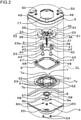
- FIG. 2 is a detailed exploded view of members of the body composition meter 1 around the load cell 5, showing an enlarged view of a part corresponding to a column-shaped area CL shown by a dot-dashed line in FIG. 1 .
- FIG. 1 shows the load cells 5 in a state where they are fixed to the bridge 23, while FIG. 2 shows the load cell 5 before it is fixed to the bridge 23.
- the body composition meter 1 comprises around the load cell 5: the bridge 23 which is a member to transfer weight to the load cell 5 and supports the load cell 5 and has a pivot 62 (refer to FIG. 4 ); a sensor holder 6 which is a member to hold the load cell 5; a leaf spring 7 for attaching the bridge 23 to the bottom cover 4; a receiving member 8 to receive (receive and hold) the weight from the subject on the resin cover 2; and low friction sheets 9a, 9b.
- the leaf spring 7 has a peripheral part fixed to the bottom cover 4, and is formed to be elastically deformable.
- the low friction sheets 9a, 9b are sheets made of fluorocarbon resin, and correspond to the sliding part in the claims.
- the low friction sheets 9a, 9b have a static friction coefficient of, for example, 0.3 or lower. Further, the low friction sheets 9a, 9b have a thickness of, for example, 0.05 mm to 0.2 mm per sheet.
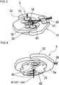
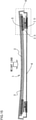
- FIG. 3 and FIG. 4 are perspective views of the load cell 5 as seen from diagonally upward and diagonally downward, respectively, while FIG. 5 is a side view of the load cell 5.
- FIG. 3 to FIG. 5 show the load cell 5 in the state where it is fixed to the bridge 23.
- the load cell 5 has a strain generating body 31 to deform when the weight of a subject on the resin cover 2 is transferred thereto, and a strain gauge 32 to generate a signal corresponding to the deformation of the strain generating body 31, and detects the weight of the subject.
- the strain generating body 31 is a single member having a line-symmetric shape and a uniform thickness, and comprises: two fixed arm parts 33 fixed to the reinforcement cover 3; two movable arm parts 34 to receive the weight from the leg 10 through the receiving member 8 and the bridge 23; a strain generating part 35 to generate a strain when the movable arm parts 34 receive the weight; and two through-holes 36 (refer to FIG. 2 ). Further, a cable 38 of the strain gauge 32 is attached in contact to the strain generating body 31 with a tape 37. This tape 37 serves to bundle the cable 38 of the strain gauge 32.
- the bridge 23 comprises on the lower surface at a central part thereof a pivot 62 having a shape formed by turning upside down a cone with a hemisphere-shaped top.
- This pivot 62 is a fulcrum to make it possible to change the inclination of the bridge 23 relative to the bottom cover 4, and is arranged to be in contact with an upper surface of the receiving member 8 in the body composition meter 1 after assembly.
- the pivot 62 has a height of, for example, 0.8 mm.
- the bridge 23 has two through-holes 40 at positions corresponding to the two through-holes 36 of the load cell 5 side. As shown in FIG. 2 and FIG.
- truncated cone-shaped bosses 42 are provided around the through-holes 40 on an upper surface 23a of the bridge 23.
- the bosses 42 of the bridge 32 serve as spacers to keep the distance between the lower surface 5a of the load cell 5 and the upper surface 23a of the bridge 23.
- the bridge 23 has at four peripheral locations thereof threaded screw holes 41 in which small screws 54 for fixing with the leaf spring 7 are screwed.
- the fixing of the load cell 5 to the bridge 23 is done with rivets 43 shown in FIG. 2 to FIG. 4 . More specifically, as shown by dashed lines in FIG. 2 , two rivets 43 are passed from downward through the through-holes 40 of the bridge 23 side and two through-holes 36 of the load cell 5 side, and then upper ends of the rivets 43 are crimped so as to fix the load cell 5 to the bridge 23.
- FIG. 6 is a top plan view of the body composition meter 1 after assembly
- FIG. 7 is a cross-sectional view of a part in a cross section along line A-A of FIG. 6 corresponding to a circle C1 shown by a dot-dashed line. As shown in FIG.
- the leaf spring 7 comprises a bottom cover attaching part 7a ("peripheral part" in the claims), an elastically deforming part 7b, and a bridge receiving part 7c.
- the bottom cover attaching part 7a is a peripheral part of the leaf spring 7, and is a part fixed to the bottom cover 4.
- the elastically deforming part 7b is a part with a tortuous shape which is provided on an inner peripheral side of the bottom cover attaching part 7a, and can elastically deform.
- the bridge receiving part 7c is a part provided on an inner peripheral side of the elastically deforming part 7b to receive the bridge 23. Further, as shown in FIG. 2 and FIG.
- the receiving member 8 comprises: a plate-shaped part 57 made of an iron plate; a flexible elastic part 58 ("elastic part” in the claims) made of rubber provided on an outer periphery of the plate-shaped part 57; and an outer ring 59 (“outer frame part” in the claims) made of iron provided on an outer periphery of the flexible elastic part 58.
- a method of attaching the receiving member 8 to the bottom cover 4 is as follows. More specifically, the low friction sheet 9a and the low friction sheet 9b are pasted on a lower surface of the receiving member 8 and an upper surface of the bottom cover 4, respectively, and then, the outer ring 59 of the receiving member 8 is welded to the bottom cover 4 so as to attach the receiving member 8 to the bottom cover 4. Thus, only the outer ring 59 is attached to the bottom cover 4 without attaching the plate-shaped part 57 and the flexible elastic part 58 of the receiving member 8 to the bottom cover 4.
- the leaf spring 7 has a hole 53 in a central part thereof.
- the leaf spring 7 is attached to the bottom cover 4 by welding joint parts 52 at four locations thereof to the bottom cover 4 in a state where the receiving member 8 is contained in the hole 53.
- FIG. 2 shows only two small screws 54, but actually the number of small screws 54 is four.
- These small screws 54 are inserted from the lower surface side of the bottom cover 4 through holes 60 (so-called clearance holes) provided in the bottom cover 4. Further, the thread parts of the small screws 54 are inserted through holes 51 of the leaf spring 7 attached to the bottom cover 4, and are screwed into the threaded screw holes 41 of the bridge 23.
- the leaf spring 7 attached to the bottom cover 4 side is screwed to the bridge 23 attached to the reinforcement cover 3 side.
- the elastically deforming part 7b of the leaf spring 7 is formed to be elastically deformable as described above, and therefore, this makes it possible to change the inclination of the bridge 23 relative to the bottom cover 4.
- the leaf spring 7 attached to the bottom cover 4 side is screwed to the bridge 23 attached to the reinforcement cover 3 side
- the legs 10 shown in FIG. 1 are pasted on the lower surface of the bottom cover 4 so as to cover the holes 60 shown in FIG. 2 .
- the leaf spring 7 is screwed to the bridge 23 attached to the reinforcement cover 3 side, and the reinforcement cover 3 is connected to the resin cover 2. Therefore, the leaf spring 7 is connected to the resin cover 2 side through the bridge 23, the load cell 5 and the reinforcement cover 3.
- FIG. 7 the positional relationship between the members around the load cell 5 in the body composition meter 1 after assembly will be described.
- the load cell 5 is supported by the bosses 42 provided on the upper surface 23a of the bridge 23, while (the lower surface 5a of) the load cell 5 and (the upper surface 23a of) the bridge 23 are in parallel to each other.
- the pivot 62 of the bridge 23 is in contact with the plate-shaped member 57 of the receiving member 8.
- the body composition meter 1 of the present embodiment is designed to make it possible to keep (the lower surface 5a of) the load cell 5 to be in parallel to (the upper surface 23a of) the bridge 23 without placing a thick rubber under the bridge, even when the resin cover 2 and the reinforcement cover 3 deflect due to the weight of the subject.
- FIG. 8 is a top plan view of a body composition meter 100 of this comparative example
- FIG. 9 is a cross-sectional view of the body composition meter 100 along line A'-A' of FIG. 8 when not loaded with the weight of a subject.
- FIG. 10 is an enlarged view of a part surrounded by a dashed line in FIG. 9 .
- FIG. 11 is a cross-sectional view of the body composition meter 100 along line A'-A' of FIG. 8 when loaded with the weight of the subject.
- FIG. 12 is an enlarged view of a part surrounded by a dashed line in FIG. 11 .
- the body composition meter 100 of the comparative example in contrast to the body composition meter 1 of the present embodiment, low friction sheets 9a, 9b are not pasted on the lower surface of a receiving member 108 and the upper surface of a bottom cover 104.
- the receiving member 108 is formed of a single member such as an iron plate or the like, and the entire receiving member 108 is fixed to the upper surface of the bottom cover 104. Thus, it is not possible to move the receiving member 108 in a horizontal direction relative to the bottom cover 104. Except for these parts, the body composition meter 100 of the comparative example is the same in configuration as the body composition meter 1 of the present embodiment.
- 111 and 112 designate electrodes and a display window of a display unit, respectively.
- 110 in FIG. 9 to FIG. 12 designates a leg of the body composition meter 100
- 142 in FIG. 10 and FIG. 12 designates a boss of the body composition meter 100.
- the load cell 105 fixed to the reinforcement cover 103 inclines when the resin cover 102 and the reinforcement cover 103 deflect due to the weight of the subject.
- the pivot 162 of the bridge 123 fixed to the load cell 105 with rivets cannot be moved to outside the body composition meter 100 (in the direction shown by arrow B in FIG. 12 ) due to a friction force generated between it and the upper surface 108a of the receiving member 108, and therefore, as shown in FIG. 12 , an inclination occurs between the lower surface 105a of the load call 105 and the upper surface 123a of the bridge 123.
- FIG. 13 is a cross-sectional view of the body composition meter 1 along line A-A of FIG. 6 when not loaded with the weight of a subject.
- FIG. 14 is an enlarged view of a part surrounded by a dashed line in FIG. 13 .
- FIG. 15 is a cross-sectional view of the body composition meter 1 along line A-A of FIG. 6 when loaded with the weight of the subject.
- FIG. 16 is an enlarged view of a part surrounded by a dashed line in FIG. 15 .
- the body composition meter 1 of the present embodiment has the low friction sheets 9a, 9b pasted on the lower surface of the receiving member 8 and the upper surface of the bottom cover 4 in contrast to the body composition meter 100 of the comparative embodiment.
- the friction coefficient of these low friction sheets 9a, 9b is set to satisfy the relationship that when the resin cover 2 and the reinforcement cover 3 deflect due to the weight of a subject, the friction force generated between (the low friction sheet 9a of) the lower surface of the plate-shaped part 57 of the receiving member 8 and (the low friction sheet 9b of) the upper surface of the bottom cover 4 is smaller than the friction force generated between the pivot 62 of the bridge 23 and the upper surface of the plate-shaped part 57 of the receiving member 8.
- the receiving member 8 of the body composition meter 1 of the present embodiment in contrast to the body composition meter 100 of the comparative example, only the part of the outer ring 59 is fixed to the bottom cover 4, and therefore, the plate-shaped part 57 of the receiving member 8 can be moved in a horizontal direction relative to (the upper surface and the lower surface of) the bottom cover 4.
- the low friction sheets 9a, 9b function so that when the resin cover 2 and the reinforcement cover 3 deflect due to the weight of the subject, the friction force acting between the lower surface of the receiving member 8 and the upper surface of the bottom cover 4 (more precisely, friction force acting between the low friction sheet 9a pasted on the lower surface of the plate-shaped part 57 of the receiving member 8 and the low friction sheet 9b pasted on the upper surface of the bottom cover 4) is smaller than the friction force generated between the pivot 62 of the bridge 23 and the upper surface of (the plate-shaped part 57 of) the receiving member 8.
- the plate-shaped part 57 of the receiving member 8 moves to outside the body composition meter 1 (in a horizontal direction relative to (the upper surface and the lower surface) of the bottom cover 4) as shown in FIG. 16 , the pivot 62 moves to outside the body composition meter 1, therefore causing a change in the inclination of the bridge 23 relative to the bottom cover 4, although due to the influence of the friction force generated between the pivot 62 and the upper surface of the plate-shaped part 57, the position of the pivot 62 of the bridge 23 relative to the plate-shaped part 57 (of the receiving member 8) is unchanged from before loaded with the weight of the subject.
- the upper surface 23a of the bridge 23 can be kept in parallel to the lower surface 5a of the load cell 5, and therefore, the weight of the subject can be applied upward in a vertical direction to the load cell 5 through the bridge 23.
- the body composition meter 1 when the resin cover 2 and the reinforcement cover 3 deflect due to the weight of the subject, it is possible to obtain an output from the load cell 5 due to a deflection of deformed shape of the strain generating part 35 without twisting (deformed shape of the strain generating part 35 similar to when the deflection of the resin cover 2 and the reinforcement cover 3 does not occur), therefore making it possible to obtain an accurate output of the load cell 5.
- the weight of the subject can be accurately measured.
- the strain generating part of the load cell 105 causes a deflection of deformed shape with twisting, thus consequently causing the output from the load cell 105 to be an output including components due to the twisting of the strain generating part, making it impossible to obtain an accurate output of the load cell 105.
- the manner of deflection of the resin cover 2 and the reinforcement cover 3 changes not only with the magnitude of the weight of the subject, but also with the size of the feet of the subject, and with the position in the upper surface of the resin cover 2 at which both feet of the subject are placed.
- the body composition meter 1 of the present embodiment regardless of the manner of deflection of the resin cover 2 and the reinforcement cover 3, it is possible to obtain an output from (the strain gauge 32 of) the load cell 5 due to the deflection of deformed shape without twisting of the strain generating part 35, and therefore, an accurate output of the load cell 5 can be obtained.
- the flexible elastic part 58 made of rubber is provided between the outer ring 59 and the plate-shaped part 57.
- the flexible elastic part 58 made of rubber deflects, while when the weight of the subject is stopped from being applied to the resin cover 2 and the reinforcement cover 3, the flexible elastic part 58 serves to bring the plate-shaped part 57 back to its position before the weight of the subject is applied.
- the elastic force of the flexible elastic part 58 of the receiving member 8 brings the plate-shaped part 57 to its position before loaded with the weight of the subject (in the direction opposite to the arrow in FIG. 16 ).
- the pivot 62 of the bridge 23 moves to inside the body composition meter 1 (in the direction opposite to the arrow in FIG. 16 ), and the inclination of the bridge 23 relative to the bottom cover 4 returns to the inclination before loaded with the weight of the subject as shown in FIG. 14 .
- the bridge 23 is provided with the pivot 62 which is a fulcrum to make it possible to change the inclination of the bridge 23 and which is in contact with the upper surface of the plate-shaped part 57 of the receiving member 8, while the flexible elastic part 58 is provided between the outer ring 59 and the plate-shaped part 57 of the receiving member 8, and further the low friction sheets 9a, 9b to enable the receiving member 8 to move in a horizontal direction relative to the bottom cover 4 are pasted on the lower surface of the plate-shaped part 57 of the receiving member 8 and the upper surface of the bottom cover 4.
- this body composition meter 1 uses, as the housing, the reinforcement cover 3 formed by combining a metal and a resin. This point will be described with reference to FIG. 7 described above.
- housings of a body composition meter or a weight scale use an iron plate (pressed part) or a resin (injection molded component).
- the entire product is required to have a thickness of 30 mm or more.
- this body composition meter 1 uses the reinforcement cover 3 formed by combining the metal and the resin in order to achieve the reduction in thickness and the reduction in weight of the housing and the entire device while maintaining its required strength. As shown in FIG.
- the reinforcement cover 3 comprises an iron plate cover 70 ("upper surface cover made of metal” in the claims), an iron plate base 71 ("bottom surface cover made of metal” in the claims) and a resin layer 72 provided between them.
- Many fine recessed parts are formed by surface treatment in the lower surface of the iron plate cover 70 and the upper surface of the iron plate base 71. These recessed parts have a diameter of, for example, 10 to 400 nm.
- the reinforcement cover 3 is formed by the iron plate cover 70, the iron plate base 71 and the resin layer 72 provided between them, and the resin is filled into the many fine recessed parts provided in the lower surface of the iron plate cover 70 and the upper surface of the iron plate base 71 so as to bond the iron plate cover 70, the resin layer 72 and the iron plate base 71, thereby making it possible for the reinforcement cover 3 to be a strong housing (hard to deflect) even if it is thin.
- the reinforcement cover 3 has a thickness of, for example, 5 to 7 mm.
- the reinforcement cover 3 has the resin layer 72 between the iron plate cover 70 and the iron plate base 71, and therefore, this can achieve the reduction in weight of the housing as compared with the conventional housing which is formed by only a metallic plate such as an iron plate.
- the use of the thin and low weight reinforcement cover 3 as the housing of the body composition meter 1, as described above, can achieve the reduction in thickness and the reduction in weight of the entire device of the body composition meter 1.
- the leaf spring 7 is used to attach the load cell 5 to the bottom cover 4 .
- the bottom cover attaching part 7a of the leaf spring 7 is attached to the bottom cover 4, and also the bridge receiving part 7c of the leaf spring 7 is connected to the bridge 23.
- the bridge 23 is connected to the strain generating body 31 of the load cell 5.
- the load cell 5 is attached to the bottom cover 4 through the bridge 23 and the lead spring 7.
- the connection between the leaf spring 7 and the bridge 23 is done with the four small screws 54, while the connection between the bridge 23 and the strain generating body 31 of the load cell 5 is done with the rivets 43.
- the first reason why the leaf spring 7 is used to fix the load cell 5 to the bottom cover 4 as described above is to make it hard for the bottom cover 4 to be disconnected when a user lifts the resin cover 2 side.
- the connection of the leaf spring 7 and the bridge 23 using the small screws 54 as described above can make it hard for the bridge 23 and the leaf spring 7 fixed to the bottom cover 4 to be disconnected from each other when a user lifts the resin cover 2 side, which therefore can make it hard for the bottom cover 4 to be disconnected.
- the second reason why the leaf spring 7 is used to fix the load cell 5 to the bottom cover 4 is that when the body composition meter 1 is loaded with the weight of a subject, the load cell 5 deflects (strains), while if the load cell 5 and the bottom cover 4 are firmly attached to each other, it hinders the deflection of the load cell 5 (strain of the strain generating part 35) and badly affects the performance of the body composition meter 1.
- the leaf spring 7 is designed to have a part which supports the lower surface of the bridge 23 and which is formed to be elastically deformable, while the load cell 5 and the bridge 23 are movably attached to the bottom cover 4 through the leaf spring 7, so as to use the elasticity of the leaf spring 7 to prevent the hindrance of the deflection of the load cell 5 (the strain of the strain generating part 35).
- the body composition meter 1 comprises a separation prevention screw 81 shown in FIG. 17 as a separation prevention member to prevent the bottom cover 4 from being separated from the resin cover 2 and the reinforcement cover 3 by a given distance or more.
- FIG. 17 is a cross-sectional view of a part in a cross section along line A-A of FIG. 6 corresponding to a circle C2 shown by a dashed line.
- the separation prevention screw 81 described above is inserted from a hole 20 of the bottom cover 4 shown in FIG. 2 and FIG. 17 , and is screwed into a screw hole 82 (refer to FIG. 17 ) provided in the resin cover 2. Further, as shown in FIG. 17 , a recessed part 20a is provided around the hole 20 of the bottom cover 4, and a gap is present between a screw head 81a of the separation prevention screw 81 and a surface 83 of the recessed part 20a in the state after the separation prevention screw 81 is attached to the resin cover 2.
- the screw head 81a of the separation prevention screw 81 attached to the resin cover 2 side is hooked to (the surface 83 of) the recessed part 20a of the bottom cover 4, thereby preventing the bottom cover 4 from being separated from the resin cover 2 and the reinforcement cover 3 by a given distance (distance D (refer to FIG. 17 ) of the gap between the screw head 81a and the surface 83 of the recessed part 20a) or more.
- the distance D is set to a distance which prevents the leaf spring 7 fixed to the bottom cover 4 side from being stretched to its limit.
- the distance of the resin cover 2 and the reinforcement cover 3 from the bottom cover 4 can be kept short, therefore making it possible to prevent the leaf spring 7 connected to both the resin cover 2 side and the bottom cover 4 side from being stretched to its limit.
- the body composition meter 1 of the present embodiment even if the pivot 62 becomes unable to move in a horizontal direction relative to the plate-shaped part 57 of the receiving member 8 due to the friction force generated between the pivot 62 of the bridge 23 and the upper surface of the plate-shaped part 57 of the receiving member 8 when the resin cover 2 and the reinforcement cover 3 deflect due to the weight of a subject, it is possible to move the plate-shaped part 57 of the receiving member 8 in a horizontal direction relative to the bottom cover 4 due to the function of the sliding part (the low friction sheet 9a pasted on the lower surface of the plate-shaped part 57 of the receiving member 8 and the low friction sheet 9b pasted on the upper surface of the bottom cover 4) provided between the lower surface of the plate-shaped part 57 of the receiving member 8 and the upper surface of the bottom cover 4.
- the inclination of the bridge 23 relative to the bottom cover 4 can be changed by moving the pivot 62 in a horizontal direction relative to the bottom cover 4.
- the upper surface 23a of the bridge 23 can be kept in parallel to the lower surface 5a of the load cell 5, similarly as when the resin cover 2 and the reinforcement cover 3 do not deflect, making it possible to stably apply an upward force from the bridge 23 in a vertical direction to the load cell 5. Therefore, regardless of the manner of deflection of the resin cover 2 and the reinforcement cover 3, an accurate output from the strain gauge 32 of the load cell 5 can be obtained, making it possible to accurately measure the weight of the subject.
- a thick rubber is not required to be placed under the bridge, therefore making it possible to achieve the reduction in thickness of the entire device.
- the friction coefficient of the sliding part (the low friction sheet 9a pasted on the lower surface of the plate-shaped part 57 of the receiving member 8 and the low friction sheet 9b pasted on the upper surface of the bottom cover 4) provided between the lower surface of the plate-shaped part 57 of the receiving member 8 and upper surface of the bottom cover 4 is set to satisfy the relationship that when the resin cover 2 and the reinforcement cover 3 deflect due to the weight of a subject, the friction force acting between the lower surface of the receiving member 8 and the upper surface of the bottom cover 4 is smaller than the friction force generated between the pivot 62 of the bridge 23 and the upper surface of the plate-shaped part 57 of the receiving member 8.
- the plate-shaped part 57 of the receiving member 8 can be reliably moved in a horizontal direction relative to the bottom cover 4, while maintaining the contact position of the pivot 62 on the upper surface of the plate-shaped part 57 of the receiving member 8. Therefore, the inclination of the bridge 23 relative to the bottom cover 4 can be reliably changed by moving the pivot 62 in a horizontal direction relative to the bottom cover 4.
- the sliding part described above uses the low friction sheets 9a, 9b made of fluorocarbon resin pasted on the lower surface of the plate-shaped part 57 of the receiving member 8 and the upper surface of the bottom cover 4.
- the friction force acting between the lower surface of the receiving member 8 and the upper surface of the bottom cover 4 when the resin cover 2 and the reinforcement cover 3 deflect due to the weight of a subject and furthermore, it is possible to achieve the reduction in thickness and the reduction in weight of the entire device as compared with the weight measurement device 200 of Patent Document 1 which places a thick rubber under the bridge.
- the receiving member 8 comprises: the plate-shaped part 57 in contact with the pivot 62 of the bridge 23; the flexible elastic part 58 made of rubber provided on an outer peripheral side of the plate-shaped part 57; and the outer ring 59 provided on an outer peripheral side of the flexible elastic part 58, in which only the outer ring 59 is attached to the bottom cover 4 without attaching the plate-shaped part 57 and the flexible elastic part 58 to the bottom cover 4.
- This configuration makes it possible that the plate-shaped part 57 of the receiving member 8 can move in a horizontal direction relative to the bottom cover 4, and furthermore that when the state in which the resin cover 2 and the reinforcement cover 3 are loaded with the weight of a subject is changed to the state in which they are not loaded with the weight of the subject, the elastic force of the flexible elastic part 58 can bring the plate-shaped part 57 back to its position before loaded with the weight of the subject.
- the body composition meter 1 of the present embodiment further comprises the leaf spring 7 to attach the bridge 23 to the bottom cover 4 side, in which the leaf spring 7 has a peripheral portion (bottom cover attaching part 7a) fixed to the bottom cover 4, and is formed to be elastically deformable. Since the leaf spring 7 is thus formed to be elastically deformable, it becomes possible to change the inclination of the bridge 23 relative to the bottom cover 4. Further, by forming the leaf spring 7 to be elastically deformable and by fixing the load cell 5 and the bridge 23 to the bottom cover 4 through the leaf spring 7 as described above, the elasticity of the leaf spring 7 can be used to prevent the hindrance of the deflection of the load cell 5 (the strain of the strain generating part 35).
- the body composition meter 1 of the present embodiment has the leaf spring 7 connected to the resin cover 2 side, and further comprises the separation prevention screw 81 to prevent the bottom cover 4 from being separated from the resin cover 2 by a given distance or more, in which the given distance is set to a distance to prevent the leaf spring 7 fixed to the bottom cover 4 side from being stretched to its limit.
- the separation prevention screw 81 to prevent the bottom cover 4 from being separated from the resin cover 2 by a given distance or more, in which the given distance is set to a distance to prevent the leaf spring 7 fixed to the bottom cover 4 side from being stretched to its limit.
- the reinforcement cover 3 comprises the iron plate cover 70, the iron plate base 71 and the resin layer 72 provided between them, and many fine recessed parts are provided in the lower surface of the iron plate cover 70 and the upper surface of the iron plate base 71, while resin of the resin layer 72 is filled into these many fine recessed parts so as to bond the iron plate cover 70, the resin layer 72 and the iron plate base 71.
- the reinforcement cover 3 can be a strong housing even if it is thin.
- the reinforcement cover 3 has the resin layer 72 between the iron plate cover 70 and the iron plate base 71, and therefore, it is possible to achieve the reduction in weight of the housing as compared with the conventional housing which is formed by only a metallic plate such as an iron plate.
- the use of the thin and low weight reinforcement cover 3 as the housing of the body composition meter 1 can achieve the reduction in thickness and the reduction in weight of the entire device of the body composition meter 1.
- the weight measurement device of the present invention is a body composition meter 1 with a function to measure the body composition of a subject.
- the weight measurement device of the present invention is not limited to this, and can be, for example, a weight scale without a function to measure the body composition of the subject, and can also be a weight measurement device such as an electronic scale for cooking or the like which measures a weight other than that of a human body.
- the "sliding part” in the claims is the low friction sheets 9a, 9b.
- the "sliding part” in the weight measurement device of the present invention is not limited to this, and can be any which has a friction force to enable the plate-shaped part of the receiving member to move relative to the bottom cover when a horizontal force is generated in the plate-shaped part.
- it can be one which is formed by subjecting at least one of the lower surface of the receiving member (for example, a part corresponding to the plate-shaped part 57 of the receiving member 8 of the present embodiment) and the upper surface of the bottom cover to plating treatment to reduce the friction coefficient.
- the "sliding part" described above can be, for example, resin such as fluorocarbon resin coated on at least one of the lower surface of the receiving member (for example, a part corresponding to the plate-shaped part 57 of the receiving member 8 of the present embodiment) and the upper surface of the bottom cover.
- the above embodiment has shown an example, in which the low friction sheets 9a, 9b are sheets made of fluorocarbon resin.
- the low friction sheet used as the "sliding part" is not limited to this, and can be, for example, a sheet made of resin other than fluorocarbon resin.
- the above embodiment has shown an example, in which the low friction sheets 9a, 9b are pasted on both the lower surface of (the plate-shaped part 57 of) the receiving member 8 and the upper surface of the bottom cover 4.
- the separation prevention screw 81 is the separation prevention screw 81.
- the "separation prevention member” is not limited to this, and can be a member with a function to prevent the bottom cover 4 from being separated from the resin cover 2 and the reinforcement cover 3 by a given distance or more.
- the "separation prevention member” can be a removal prevention part 91 having a locking hook 90 and integrally formed with the resin cover 2. The removal prevention part 91 with the locking hook 90 is pressed into the hole 20 of the bottom cover 4 when the body composition meter 1 is assembled.
- the locking hook 90 of the removal prevention part 91 provided on the resin cover 2 is hooked by (the surface 83) of the recessed part 20a of the bottom cover 4 so as to prevent the bottom cover 4 from being separated from the resin cover 2 and the reinforcement cover 3 by a given distance (distance D' (refer to FIG. 18 ) between the locking hook 90 and the surface 83 of the recessed part 20a) or more.
- the above embodiment has shown an example, in which the separation prevention screw 81 is screwed into the screw hole 82 provided in the resin cover 2 and attached to the resin cover.
- the separation prevention screw can be screwed into a screw hole provided in the reinforcement cover and attached to the reinforcement cover.
- the above embodiment has shown an example, in which the "upper surface cover made of metal” and the “bottom surface cover made of metal” in the claims are the iron plate cover 70 and the iron plate base 71.
- the "upper surface cover made of metal” and the “bottom surface cover made of metal” are not limited to this, and can be, for example, plates made of metal such as aluminum, copper, stainless steel or the like.
- the bottom cover 4 is designed to have almost the same area as the entire device, and the four legs 10 are provided at positions corresponding to the load cells 5 in the bottom cover 4.
- the four legs 10 are provided at positions corresponding to the load cells 5 in the bottom cover 4.
- the upper and lower surfaces of these units have an area of, for example, about ⁇ 50 mm.
Landscapes
- Physics & Mathematics (AREA)
- General Physics & Mathematics (AREA)
- Health & Medical Sciences (AREA)
- Life Sciences & Earth Sciences (AREA)
- Engineering & Computer Science (AREA)
- Medical Informatics (AREA)
- Biophysics (AREA)
- Pathology (AREA)
- Dentistry (AREA)
- Biomedical Technology (AREA)
- Heart & Thoracic Surgery (AREA)
- Oral & Maxillofacial Surgery (AREA)
- Molecular Biology (AREA)
- Surgery (AREA)
- Animal Behavior & Ethology (AREA)
- General Health & Medical Sciences (AREA)
- Public Health (AREA)
- Veterinary Medicine (AREA)
- Measurement Of Force In General (AREA)
Abstract
Description
- The present invention relates to a weight measurement device for measuring the weight of a measurement target.
- Conventionally, there are known weight measurement devices for measuring the weight of a measurement target such as a human body. Generally, a weight measurement device has at least one load cell (normally four in the case of a weight scale) to which the weight of a measurement target is transferred. A load cell has a strain generating body to deform when the weight of the measurement target is transferred thereto, and a strain gauge for generating a signal corresponding to the deformation of the strain generating body. Based on the signal output from the strain gauge described above, a processing circuitry on a board calculates the weight of the measurement target.
- In conventional weight measurement devices, there is a
weight measurement device 200 as shown inFIG. 19 which is designed so that when a measurement target is placed on anupper surface cover 202 while a rubber 208 is sandwiched between a bridge 223 and aleg 210, a weight (upward force) from theleg 210 is transferred to (movable arm parts of) aload cell 205 through the rubber 208 and the bridge 223 (refer for example to Patent Document 1). Note that amember 242 inFIG. 19 is a boss (a member equivalent to theboss 42 inFIG. 2 described later) integrally formed with the bride 223, and serves as a spacer to keep the distance between a lower surface 205a of theload cell 205 and an upper surface 223a of the bridge 223. In thisweight measurement device 200, as shown on the right side ofFIG. 19 , when theupper surface cover 202 and ahousing 203 are loaded with the weight of the measurement target, theload cell 205 inclines as theupper surface cover 202 and thehousing 203 deflect due to the weight. Corresponding to this inclination, the rubber 208 is a little compressed while deforming in a horizontal direction, causing the upper surface of the rubber 208 to incline, whereby the bridge 223 inclines corresponding to the inclination of theload cell 205, making it possible to keep the upper surface 223a of the bridge 223 to be in parallel to the lower surface 205a of theload cell 205. - According to this
weight measurement device 200, as described above, the upper surface 223a of the bridge 223 can be kept in parallel to the lower surface 205a of theload cell 205, and therefore, upward force in the vertical direction can be stably applied to (the movable arm parts of) theload cell 205 from the bridge 223. Therefore, regardless of the manner of deflection of theupper surface cover 202 and thehousing 203, an accurate output from (the strain gauge of) theload cell 205 can be obtained, thus making it possible to accurately measure the weight of the measurement target. - [Patent Document 1]
Japanese Laid-open Patent Publication 2014-66572 - However, in order to allow that the rubber 208 is sandwiched between the bridge 223 and the
leg 210, and this rubber 208 is used to keep the upper surface 223a of the bridge 223 to be in parallel to the lower surface 205a of theload cell 205 as in the conventionalweight measurement device 200 described above, the rubber 208 is required to be some sufficiently thick rubber (for example, 5 mm), causing the problem that it is not possible to achieve reduction in the thickness of the entire device. - An object of the present invention is to solve the problems described above and to provide a weight measurement device which can obtain an accurate output from a load cell, and can accurately measure the weight of the measurement target, regardless of the manner of deflection of an upper surface cover and so on, and which can achieve reduction in the thickness of the entire device.
- In order to solve the above problem, a weight measurement device according to the present invention comprises: an upper surface cover on which a measurement target is placed; a load cell to detect weight of the measurement target placed on the upper surface cover; a bridge to support the load cell; a receiving member to receive the weight of the measurement target placed on the upper surface cover; and a bottom surface cover provided on a lower surface side of the receiving member, wherein the weight measurement device further comprises a sliding part provided between the lower surface of the receiving member and an upper surface of the bottom surface cover to enable the receiving member to move in a horizontal direction relative to the bottom cover, and wherein the bridge comprises a pivot which is a fulcrum to make it possible to change inclination of the bridge relative to the bottom surface cover and is in contact with an upper surface of the receiving member.
- In this weight measurement device, it is preferable that friction coefficient of the sliding part is set to satisfy the relationship that when the upper surface cover deflects due to the weight of the measurement target placed on the upper surface cover, friction force generated between the receiving member and the bottom surface cover is smaller than friction force generated between the pivot and the receiving member.
- In this weight measurement device, the sliding part can be a sheet made of resin pasted on at least one of the lower surface of the receiving member and the upper surface of the bottom surface cover.
- In this weight measurement device, the sheet made of resin can be a sheet made of fluorocarbon resin.
- In this weight measurement device, the sliding part can be resin coated on at least one of the lower surface of the receiving member and the upper surface of the bottom surface cover.
- In this weight measurement device, the coated resin can be fluorocarbon resin.
- In this weight measurement device, the sliding part can be at least one of the lower surface of the receiving member and the upper surface of the bottom surface cover having been subjected to plating treatment.
- In this weight measurement device, the receiving member can comprise: a plate-shaped part in contact with the pivot; an elastic part provided on an outer periphery of the plate-shaped part; and an outer frame part provided on an outer periphery of the elastic part, wherein only the outer frame part can be attached to the bottom surface cover without attaching the plate-shaped part and the elastic part to the bottom surface cover.
- In this weight measurement device, it can further comprise a leaf spring to attach the bridge to the bottom surface cover side, wherein the leaf spring can have a peripheral part fixed to the bottom surface cover, and is formed to be elastically deformable.
- In this weight measurement device, the leaf spring can be connected to the upper surface cover side, wherein the weight measurement device can further comprise a separation prevention member to prevent the bottom surface cover from being separated from the upper surface cover by a given distance or more, and wherein the given distance can be a distance to prevent the leaf spring fixed to the bottom surface cover side from being stretched to its limit.
- In this weight measurement device, it can further comprise a reinforcement cover connected to the upper surface cover, wherein the reinforcement cover can comprise an upper surface cover made of metal, a bottom surface cover made of metal, and a resin layer provided between the upper surface cover made of metal and the bottom surface cover made of metal, wherein many fine recessed parts can be formed in a lower surface of the upper surface cover made of metal and an upper surface of the bottom surface cover made of metal, and wherein resin of the resin layer can be filled into the many fine recessed parts so as to bond the upper surface cover made of metal, the resin layer and the bottom surface cover made of metal.
- According to the present invention, even if the pivot becomes unable to move in a horizontal direction relative to the receiving member due to the friction force generated between the pivot of the bridge and the upper surface of the receiving member when the upper surface cover deflects due to the weight of a measurement target, it is possible to move the receiving member in a horizontal direction relative to the bottom surface cover due to the function of the sliding part provided between the lower surface of the receiving member and the upper surface of the bottom surface cover. Therefore, the inclination of the bridge relative to the bottom surface cover can be changed by moving the pivot in a horizontal direction relative to the bottom surface cover. Thus, when the upper surface cover deflects due to the weight of the measurement target, it is possible to keep the inclination between the upper surface of the bridge and the lower surface of the load cell (for example, to keep the upper surface of the bridge to be in parallel to the lower surface of the load cell) in the state when the upper surface cover does not deflect, making it possible to stably apply an upward force from the bridge in a vertical direction to the lower surface of the load cell. Therefore, regardless of the manner of deflection of the upper surface cover, an accurate output from the load cell can be obtained, making it possible to accurately measure the weight of the measurement target. In addition, in contrast to the weight measurement device shown in
Patent Document 1, a thick rubber is not required to be placed under the bridge, therefore making it possible to achieve the reduction in thickness of the entire device. -
- [
FIG. 1 ] Exploded perspective view of a body composition meter according to an exemplary embodiment of the present invention. - [
FIG. 2 ] Detailed exploded view of members of the body composition meter around a load cell. - [
FIG. 3 ] Perspective view of the load cell of the body composition meter as seen from diagonally upward. - [
FIG. 4 ] Perspective view of the load cell as seen from diagonally downward. - [
FIG. 5 ] Side view of the load cell. - [
FIG. 6 ] Top plan view of the body composition meter. - [
FIG. 7 ] Cross-sectional view of a part in a cross section along line A-A ofFIG. 6 corresponding to a circle C1. - [
FIG. 8 ] Top plan view of a body composition meter according to a comparative example. - [
FIG. 9 ] Cross-sectional view of the body composition meter according to the comparative example along line A'-A' ofFIG. 8 when not loaded with the weight of a subject. - [
FIG. 10 ] Enlarged view of a part surrounded by a dashed line inFIG. 9 . - [
FIG. 11 ] Cross-sectional view of the body composition meter according to the comparative example along line A'-A' ofFIG. 8 when loaded with the weight of the subject. - [
FIG. 12 ] Enlarged view of a part surrounded by a dashed line inFIG. 11 . - [
FIG. 13 ] Cross-sectional view of the present body composition meter along line A-A ofFIG. 6 when not loaded with the weight of a subject. - [
FIG. 14 ] Enlarged view of a part surrounded by a dashed line inFIG. 13 . - [
FIG. 15 ] Cross-sectional view of the present body composition meter along line A-A ofFIG. 6 when loaded with the weight of the subject. - [
FIG. 16 ] Enlarged view of a part surrounded by a dashed line inFIG. 15 . - [
FIG. 17 ] Cross-sectional view of a part in a cross section along line A-A ofFIG. 6 corresponding to a circle C2. - [
FIG. 18 ] Cross-sectional view of a part around a leg part in a body composition meter according to a Modified Example 3 of the present invention. - [
FIG. 19 ] Explanatory view of the configuration around a load cell according to an example of a conventional weight measurement device. - Hereinafter, an exemplary embodiment of the present invention will be described with reference to the drawings. The present embodiment describes an example in which the weight measurement device of the present invention is a body composition meter.
-
FIG. 1 is an exploded perspective view of the entire body composition meter according to the present embodiment. Thebody composition meter 1 has a function to measure the weight of a subject, and a function to measure the body composition of the subject such as body fat rate, amount of muscle, estimated amount of bone, visceral fat level, amount of basal metabolism, body water rate and so on. As shown inFIG. 1 , thebody composition meter 1 comprises, as its housing, a resin cover 2 ("upper surface cover" in the claims) on which a subject is placed, areinforcement cover 3 formed by combining a metal and a resin, and a bottom cover 4 ("bottom surface cover" in the claims). Although details of thereinforcement cover 3 will be described later, thisreinforcement cover 3 is a member to increase the strength of theresin cover 2 by being bonded to theresin cover 2. Thebottom cover 4 is formed by a material made of metal such as steel plate. Further, as shown inFIG. 1 , thebody composition meter 1 compriseslegs 10 placed on four corners of the bottom surface of thebottom cover 4. - As shown in
FIG. 1 , thebody composition meter 1 comprises fourelectrodes 11 on an upper surface of theresin cover 2 to measure a bioelectrical impedance of a subject. Theseelectrodes 11 include left and right current supply electrodes to apply current to the soles of both left and right feet of the subject, and left and right voltage detection electrodes to detect a voltage corresponding to a potential difference generated between the soles of both feet of the subject due to the current application from the current supply electrodes. Further, thebody composition meter 1 comprises a display unit. This display unit is formed by adisplay window 12 provided in the upper surface of theresin cover 2, and a not shown LCD module attached to a recessedpart 13 provided on an upper surface of thereinforcement cover 3. The weight, body composition and so on of the subject are displayed on this display unit. - Further, a not shown board is attached to a recessed part provided on a back surface side of a projected
part 14 of thereinforcement cover 3. This board comprises a processing circuitry to perform a measurement process of the weight of the subject, a measurement process on various body compositions of the subject and other processes, and so on. The LCD module placed on the upper surface side of thereinforcement cover 3 described above is connected to the board placed on the bottom surface side of thereinforcement cover 3. More specifically, a flexible cable integrally provided with the LCD module is passed through a through-hole 18 formed in a central part of thereinforcement cover 3, and an end of the flexible cable is connected to the board on the bottom surface side of thereinforcement cover 3. Further, holes 17 are formed in thereinforcement cover 3 having a substantially rectangular shape at positions corresponding to its four corners in order to secure space to allow the movable arm parts 34 (refer toFIG. 2 and so on) of theload cells 5 to move upward when the subject steps on theresin cover 2. In addition, ahole 19 is formed in thereinforcement cover 3 in order to secure space for abattery box 21 provided on thebottom cover 4. - Next, referring to
FIG. 2 in addition toFIG. 1 described above, members of thebody composition meter 1 around theload cell 5 will be described.FIG. 2 is a detailed exploded view of members of thebody composition meter 1 around theload cell 5, showing an enlarged view of a part corresponding to a column-shaped area CL shown by a dot-dashed line inFIG. 1 . Note thatFIG. 1 shows theload cells 5 in a state where they are fixed to thebridge 23, whileFIG. 2 shows theload cell 5 before it is fixed to thebridge 23. - As shown in
FIG. 2 , thebody composition meter 1 comprises around the load cell 5: thebridge 23 which is a member to transfer weight to theload cell 5 and supports theload cell 5 and has a pivot 62 (refer toFIG. 4 ); asensor holder 6 which is a member to hold theload cell 5; aleaf spring 7 for attaching thebridge 23 to thebottom cover 4; a receivingmember 8 to receive (receive and hold) the weight from the subject on theresin cover 2; andlow friction sheets leaf spring 7 has a peripheral part fixed to thebottom cover 4, and is formed to be elastically deformable. Thelow friction sheets low friction sheets low friction sheets - Next, referring to
FIG. 3 to FIG. 5 in addition toFIG. 2 described above, the structure of theload cell 5 will be described.FIG. 3 and FIG. 4 are perspective views of theload cell 5 as seen from diagonally upward and diagonally downward, respectively, whileFIG. 5 is a side view of theload cell 5.FIG. 3 to FIG. 5 show theload cell 5 in the state where it is fixed to thebridge 23. Theload cell 5 has astrain generating body 31 to deform when the weight of a subject on theresin cover 2 is transferred thereto, and astrain gauge 32 to generate a signal corresponding to the deformation of thestrain generating body 31, and detects the weight of the subject. Thestrain generating body 31 is a single member having a line-symmetric shape and a uniform thickness, and comprises: two fixedarm parts 33 fixed to thereinforcement cover 3; twomovable arm parts 34 to receive the weight from theleg 10 through the receivingmember 8 and thebridge 23; astrain generating part 35 to generate a strain when themovable arm parts 34 receive the weight; and two through-holes 36 (refer toFIG. 2 ). Further, acable 38 of thestrain gauge 32 is attached in contact to thestrain generating body 31 with atape 37. Thistape 37 serves to bundle thecable 38 of thestrain gauge 32. - As shown in
FIG. 4 andFIG. 5 , thebridge 23 comprises on the lower surface at a central part thereof apivot 62 having a shape formed by turning upside down a cone with a hemisphere-shaped top. Thispivot 62 is a fulcrum to make it possible to change the inclination of thebridge 23 relative to thebottom cover 4, and is arranged to be in contact with an upper surface of the receivingmember 8 in thebody composition meter 1 after assembly. Thepivot 62 has a height of, for example, 0.8 mm. Further, as shown inFIG. 2 , thebridge 23 has two through-holes 40 at positions corresponding to the two through-holes 36 of theload cell 5 side. As shown inFIG. 2 andFIG. 5 , truncated cone-shapedbosses 42 are provided around the through-holes 40 on anupper surface 23a of thebridge 23. Thus, as shown inFIG. 5 , at theupper surface 23a of thebridge 23, only the upper surfaces of the twobosses 42 are brought in contact with the lower surface of theload cell 5 in the state whereload cell 5 is fixed to thebridge 23. In other words, thebosses 42 of thebridge 32 serve as spacers to keep the distance between thelower surface 5a of theload cell 5 and theupper surface 23a of thebridge 23. Further, as shown inFIG. 2 , thebridge 23 has at four peripheral locations thereof threaded screw holes 41 in whichsmall screws 54 for fixing with theleaf spring 7 are screwed. - Next, a method of attaching the
load cell 5, thebridge 23 and thesensor holder 6 to thereinforcement cover 3 will be described. First, the fixing of theload cell 5 to thebridge 23 is done withrivets 43 shown inFIG. 2 to FIG. 4 . More specifically, as shown by dashed lines inFIG. 2 , tworivets 43 are passed from downward through the through-holes 40 of thebridge 23 side and two through-holes 36 of theload cell 5 side, and then upper ends of therivets 43 are crimped so as to fix theload cell 5 to thebridge 23. Then, fixedarm parts 33 of theload cell 5 in a state where it is fixed to thebridge 23 are fitted into aframe 47 of thesensor holder 6, and thereafter, thesensor holder 6 with theload cell 5 fitted therein is attached to a frame 73 (refer toFIG. 7 ) provided on the back surface side of thereinforcement cover 3. Further, as shown by dashed lines inFIG. 2 ,small screws 50 are screwed in screw holes 49 of thereinforcement cover 3 and screwholes 48 of thesensor holder 6 so as to fix (screw) thereinforcement cover 3 to thesensor holder 6, whereby theload cell 5, thebridge 23 and thesensor holder 6 are attached to thereinforcement cover 3. - Further, among the members around the
load cell 5 shown inFIG. 2 , theleaf spring 7 and the receivingmember 8 are attached to thebottom cover 4 side. Before describing a method of attaching theleaf spring 7 and the receivingmember 8, the structure of theleaf spring 7 and the receivingmember 8 will be described with reference toFIG. 6 andFIG. 7 in addition toFIG. 2 described above.FIG. 6 is a top plan view of thebody composition meter 1 after assembly, whileFIG. 7 is a cross-sectional view of a part in a cross section along line A-A ofFIG. 6 corresponding to a circle C1 shown by a dot-dashed line. As shown inFIG. 2 , theleaf spring 7 comprises a bottom cover attaching part 7a ("peripheral part" in the claims), an elastically deformingpart 7b, and abridge receiving part 7c. The bottom cover attaching part 7a is a peripheral part of theleaf spring 7, and is a part fixed to thebottom cover 4. The elastically deformingpart 7b is a part with a tortuous shape which is provided on an inner peripheral side of the bottom cover attaching part 7a, and can elastically deform. Thebridge receiving part 7c is a part provided on an inner peripheral side of the elastically deformingpart 7b to receive thebridge 23. Further, as shown inFIG. 2 andFIG. 7 , the receivingmember 8 comprises: a plate-shapedpart 57 made of an iron plate; a flexible elastic part 58 ("elastic part" in the claims) made of rubber provided on an outer periphery of the plate-shapedpart 57; and an outer ring 59 ("outer frame part" in the claims) made of iron provided on an outer periphery of the flexibleelastic part 58. - A method of attaching the receiving
member 8 to thebottom cover 4 is as follows. More specifically, thelow friction sheet 9a and thelow friction sheet 9b are pasted on a lower surface of the receivingmember 8 and an upper surface of thebottom cover 4, respectively, and then, theouter ring 59 of the receivingmember 8 is welded to thebottom cover 4 so as to attach the receivingmember 8 to thebottom cover 4. Thus, only theouter ring 59 is attached to thebottom cover 4 without attaching the plate-shapedpart 57 and the flexibleelastic part 58 of the receivingmember 8 to thebottom cover 4. - Further, as shown in
FIG. 2 , theleaf spring 7 has ahole 53 in a central part thereof. Theleaf spring 7 is attached to thebottom cover 4 by weldingjoint parts 52 at four locations thereof to thebottom cover 4 in a state where the receivingmember 8 is contained in thehole 53. - The
bridge 23, which together with theload cell 5 and thesensor holder 6 described above is attached to thereinforcement cover 3 side, is fixed with thesmall screws 54 to theleaf spring 7 attached to thebottom cover 4 side. Note thatFIG. 2 shows only twosmall screws 54, but actually the number ofsmall screws 54 is four. Thesesmall screws 54 are inserted from the lower surface side of thebottom cover 4 through holes 60 (so-called clearance holes) provided in thebottom cover 4. Further, the thread parts of thesmall screws 54 are inserted throughholes 51 of theleaf spring 7 attached to thebottom cover 4, and are screwed into the threaded screw holes 41 of thebridge 23. Thus, theleaf spring 7 attached to thebottom cover 4 side is screwed to thebridge 23 attached to thereinforcement cover 3 side. According to this configuration, the elastically deformingpart 7b of theleaf spring 7 is formed to be elastically deformable as described above, and therefore, this makes it possible to change the inclination of thebridge 23 relative to thebottom cover 4. - As described above, after the
leaf spring 7 attached to thebottom cover 4 side is screwed to thebridge 23 attached to thereinforcement cover 3 side, thelegs 10 shown inFIG. 1 are pasted on the lower surface of thebottom cover 4 so as to cover theholes 60 shown inFIG. 2 . As described above, theleaf spring 7 is screwed to thebridge 23 attached to thereinforcement cover 3 side, and thereinforcement cover 3 is connected to theresin cover 2. Therefore, theleaf spring 7 is connected to theresin cover 2 side through thebridge 23, theload cell 5 and thereinforcement cover 3. - Next, referring to
FIG. 7 , the positional relationship between the members around theload cell 5 in thebody composition meter 1 after assembly will be described. As shown inFIG. 7 , when not loaded with the weight of a subject, theload cell 5 is supported by thebosses 42 provided on theupper surface 23a of thebridge 23, while (thelower surface 5a of) theload cell 5 and (theupper surface 23a of) thebridge 23 are in parallel to each other. Further, as shown inFIG. 7 , in thebody composition meter 1 after assembly, thepivot 62 of thebridge 23 is in contact with the plate-shapedmember 57 of the receivingmember 8. - Next, referring to
FIG. 3 to FIG. 5 described above, the influence of the inclination between (thelower surface 5a of) theload cell 5 and (theupper surface 23a of) thebridge 23 on the output of thestrain gauge 32 of theload cell 5 will be described. As shown inFIG. 5 , when (thelower surface 5a of) theload cell 5 and (theupper surface 23a of) thebridge 23 are in parallel to each other, the weight of the subject is applied upward in a vertical direction from the leg 10 (refer toFIG. 1 ,FIG. 7 ,FIG. 10 and so on) to thelower surface 5a of theload cell 5 through thepivot 62 of thebridge 23 as shown by the solid line arrow and the dash line arrow ofFIG. 5 . However, when (thelower surface 5a of) theload cell 5 and (theupper surface 23a of) thebridge 23 are brought to a state where they are not in parallel (or are inclined) to each other, it leads to a state where the weight of the subject is not applied upward in a vertical direction to theload cell 5. Thus, when (thelower surface 5a of) theload cell 5 and (theupper surface 23a of) thebridge 23 are not in parallel to each other, the manner of strain of thestrain generating part 35 of theload cell 5 changes compared with when they are in parallel to each other, thus causing an error in the output value of thestain gauge 32 of theload cell 5, consequently making it impossible for thebody composition meter 1 to accurately measure the weight of the subject. - In contrast to the weight measurement device shown in the
above Patent Document 1, thebody composition meter 1 of the present embodiment is designed to make it possible to keep (thelower surface 5a of) theload cell 5 to be in parallel to (theupper surface 23a of) thebridge 23 without placing a thick rubber under the bridge, even when theresin cover 2 and thereinforcement cover 3 deflect due to the weight of the subject. - The original idea to keep the
load cell 5 to be in parallel to thebridge 23 will be described with reference to a body composition meter of a comparative example relative to thebody composition meter 1 of the present embodiment.FIG. 8 is a top plan view of abody composition meter 100 of this comparative example, whileFIG. 9 is a cross-sectional view of thebody composition meter 100 along line A'-A' ofFIG. 8 when not loaded with the weight of a subject.FIG. 10 is an enlarged view of a part surrounded by a dashed line inFIG. 9 .FIG. 11 is a cross-sectional view of thebody composition meter 100 along line A'-A' ofFIG. 8 when loaded with the weight of the subject.FIG. 12 is an enlarged view of a part surrounded by a dashed line inFIG. 11 . - In the
body composition meter 100 of the comparative example in contrast to thebody composition meter 1 of the present embodiment,low friction sheets member 108 and the upper surface of abottom cover 104. Further, in thebody composition meter 100 of the comparative example in contrast to thebody composition meter 1 of the present embodiment, the receivingmember 108 is formed of a single member such as an iron plate or the like, and the entire receivingmember 108 is fixed to the upper surface of thebottom cover 104. Thus, it is not possible to move the receivingmember 108 in a horizontal direction relative to thebottom cover 104. Except for these parts, thebody composition meter 100 of the comparative example is the same in configuration as thebody composition meter 1 of the present embodiment. Note that inFIG. 8 , 111 and 112 designate electrodes and a display window of a display unit, respectively. Further, 110 inFIG. 9 to FIG. 12 designates a leg of thebody composition meter 100, while 142 inFIG. 10 andFIG. 12 designates a boss of thebody composition meter 100. - As shown in
FIG. 11 andFIG. 12 , according to the configuration of thebody composition meter 100, theload cell 105 fixed to thereinforcement cover 103 inclines when theresin cover 102 and thereinforcement cover 103 deflect due to the weight of the subject. However, the pivot 162 of the bridge 123 fixed to theload cell 105 with rivets cannot be moved to outside the body composition meter 100 (in the direction shown by arrow B inFIG. 12 ) due to a friction force generated between it and the upper surface 108a of the receivingmember 108, and therefore, as shown inFIG. 12 , an inclination occurs between the lower surface 105a of theload call 105 and the upper surface 123a of the bridge 123. In this way, when the lower surface 105a of theload cell 105 and the upper surface 123a of the bridge 123 are brought to a state where they are not in parallel (or are inclined) to each other, it leads to a state where the weight of the subject is not applied upward in a vertical direction to theload cell 105. Therefore, the manner of strain of theload cell 105 in the strain region changes depending on the manner of deflection of theresin cover 102 and thereinforcement cover 103, thus making it impossible to obtain an accurate output of (the strain gauge of) theload cell 105. Therefore, it is not possible for thebody composition meter 100 to accurately measure the weight of the subject. - On the other hand, according to the
body composition meter 1 of the present embodiment, thelower surface 5a of the load cell5 and theupper surface 23a of thebridge 23 can be kept in parallel to each other. The reason for this will be described with reference toFIG. 13 to FIG. 16 .FIG. 13 is a cross-sectional view of thebody composition meter 1 along line A-A ofFIG. 6 when not loaded with the weight of a subject.FIG. 14 is an enlarged view of a part surrounded by a dashed line inFIG. 13 .FIG. 15 is a cross-sectional view of thebody composition meter 1 along line A-A ofFIG. 6 when loaded with the weight of the subject.FIG. 16 is an enlarged view of a part surrounded by a dashed line inFIG. 15 . - As shown in
FIG. 14 andFIG. 16 , thebody composition meter 1 of the present embodiment has thelow friction sheets member 8 and the upper surface of thebottom cover 4 in contrast to thebody composition meter 100 of the comparative embodiment. The friction coefficient of theselow friction sheets resin cover 2 and thereinforcement cover 3 deflect due to the weight of a subject, the friction force generated between (thelow friction sheet 9a of) the lower surface of the plate-shapedpart 57 of the receivingmember 8 and (thelow friction sheet 9b of) the upper surface of thebottom cover 4 is smaller than the friction force generated between thepivot 62 of thebridge 23 and the upper surface of the plate-shapedpart 57 of the receivingmember 8. Further, in the receivingmember 8 of thebody composition meter 1 of the present embodiment in contrast to thebody composition meter 100 of the comparative example, only the part of theouter ring 59 is fixed to thebottom cover 4, and therefore, the plate-shapedpart 57 of the receivingmember 8 can be moved in a horizontal direction relative to (the upper surface and the lower surface of) thebottom cover 4. - As shown in
FIG. 15 andFIG. 16 , in thebody composition meter 1 of the present embodiment, when theresin cover 2 and thereinforcement cover 3 deflect due to the weight of the subject, theload cell 5 fixed to thereinforcement cover 3 inclines, and as it inclines, thepivot 62 of thebridge 23 fixed to theload cell 5 attempts to move to outside the body composition meter 1 (in the direction shown by arrow inFIG. 16 ). Here, thelow friction sheets resin cover 2 and thereinforcement cover 3 deflect due to the weight of the subject, the friction force acting between the lower surface of the receivingmember 8 and the upper surface of the bottom cover 4 (more precisely, friction force acting between thelow friction sheet 9a pasted on the lower surface of the plate-shapedpart 57 of the receivingmember 8 and thelow friction sheet 9b pasted on the upper surface of the bottom cover 4) is smaller than the friction force generated between thepivot 62 of thebridge 23 and the upper surface of (the plate-shapedpart 57 of) the receivingmember 8. Thus, when theresin cover 2 and thereinforcement cover 3 deflect, and theload cell 5 inclines due to the weight of the subject, the plate-shapedpart 57 of the receivingmember 8 moves to outside the body composition meter 1 (in a horizontal direction relative to (the upper surface and the lower surface) of the bottom cover 4) as shown inFIG. 16 , thepivot 62 moves to outside thebody composition meter 1, therefore causing a change in the inclination of thebridge 23 relative to thebottom cover 4, although due to the influence of the friction force generated between thepivot 62 and the upper surface of the plate-shapedpart 57, the position of thepivot 62 of thebridge 23 relative to the plate-shaped part 57 (of the receiving member 8) is unchanged from before loaded with the weight of the subject. - In this way, when the
resin cover 2 and thereinforcement cover 3 deflect due to the weight of the subject, theupper surface 23a of thebridge 23 can be kept in parallel to thelower surface 5a of theload cell 5, and therefore, the weight of the subject can be applied upward in a vertical direction to theload cell 5 through thebridge 23. Thus, according to thebody composition meter 1, when theresin cover 2 and thereinforcement cover 3 deflect due to the weight of the subject, it is possible to obtain an output from theload cell 5 due to a deflection of deformed shape of thestrain generating part 35 without twisting (deformed shape of thestrain generating part 35 similar to when the deflection of theresin cover 2 and thereinforcement cover 3 does not occur), therefore making it possible to obtain an accurate output of theload cell 5. Thus, the weight of the subject can be accurately measured. In contrast to this, as shown inFIG. 11 andFIG. 12 , when the upper surface 123a of the bridge 123 cannot be kept in parallel to the lower surface 105a of theload cell 105, and the weight of the subject cannot be applied upward in a vertical direction to theload cell 105 through the bridge 123, the strain generating part of theload cell 105 causes a deflection of deformed shape with twisting, thus consequently causing the output from theload cell 105 to be an output including components due to the twisting of the strain generating part, making it impossible to obtain an accurate output of theload cell 105. - Note that the manner of deflection of the
resin cover 2 and thereinforcement cover 3 changes not only with the magnitude of the weight of the subject, but also with the size of the feet of the subject, and with the position in the upper surface of theresin cover 2 at which both feet of the subject are placed. However, according to thebody composition meter 1 of the present embodiment, regardless of the manner of deflection of theresin cover 2 and thereinforcement cover 3, it is possible to obtain an output from (thestrain gauge 32 of) theload cell 5 due to the deflection of deformed shape without twisting of thestrain generating part 35, and therefore, an accurate output of theload cell 5 can be obtained. - Further, in the receiving
member 8 of thebody composition meter 1 of the present embodiment, as described above, only the part of theouter ring 59 is fixed to thebottom cover 4, while as shown inFIG. 16 , the flexibleelastic part 58 made of rubber is provided between theouter ring 59 and the plate-shapedpart 57. When the weight of the subject is applied to theresin cover 2 and thereinforcement cover 3 to cause a horizontal force to be generated in the plate-shapedpart 57 through thepivot 62 of thebridge 23, the flexibleelastic part 58 made of rubber deflects, while when the weight of the subject is stopped from being applied to theresin cover 2 and thereinforcement cover 3, the flexibleelastic part 58 serves to bring the plate-shapedpart 57 back to its position before the weight of the subject is applied. More specifically, when the subject steps down from the top of theresin cover 2 to cause the weight of the subject to be stopped from being applied to theresin cover 2 and thereinforcement cover 3, the deflection of theresin cover 2 and thereinforcement cover 3 disappears as shown inFIG. 13 andFIG. 14 . Thus, in contrast to when loaded with the weight of the subject, the inclination of theload cell 5 fixed to thereinforcement cover 3 disappears (theload cell 5 returns from the state shown inFIG. 16 back to the state shown inFIG. 14 ). At this time, along with the movement of theload cell 5 from the state shown inFIG. 16 back to the state shown inFIG. 14 , the elastic force of the flexibleelastic part 58 of the receivingmember 8 brings the plate-shapedpart 57 to its position before loaded with the weight of the subject (in the direction opposite to the arrow inFIG. 16 ). Thus, thepivot 62 of thebridge 23 moves to inside the body composition meter 1 (in the direction opposite to the arrow inFIG. 16 ), and the inclination of thebridge 23 relative to thebottom cover 4 returns to the inclination before loaded with the weight of the subject as shown inFIG. 14 . - Note that even without pasting the
low friction sheets member 8 and the upper surface of thebottom cover 4 as in thebody composition meter 1 of the present embodiment, it is possible to keep the upper surface of the bridge to be in parallel to the lower surface of the load cell when the weight of the subject is applied, similarly as in thebody composition meter 1 of the present embodiment, if a method such as coating a lubricating agent on (particularly the top part of) the pivot of the bridge is used to allow the pivot in contact with the receiving member or the upper surface of the bottom cover to slide. However, such a configuration causes the pivot loaded with a point load (concentrated load) to move in a horizontal direction relative to (the upper surface of) the bottom cover, and therefore, the pivot is likely to wear, causing the device (particularly the pivot) to have a low durability. In contrast, according to thebody composition meter 1 of the present embodiment, the plate-shapedpart 57 of the receivingmember 8 loaded with the load from theleg 10 in the form of surface load moves in a horizontal direction relative to (the upper surface of) thebottom cover 4, and therefore, the wear between the parts and members is less likely to occur compared with the case of sliding the pivot as described above. - Next, the original idea used in the
body composition meter 1 to achieve the reduction in thickness and the reduction in weight of the entire device, while securing its accuracy, will be described. First, in thebody composition meter 1 as described above, thebridge 23 is provided with thepivot 62 which is a fulcrum to make it possible to change the inclination of thebridge 23 and which is in contact with the upper surface of the plate-shapedpart 57 of the receivingmember 8, while the flexibleelastic part 58 is provided between theouter ring 59 and the plate-shapedpart 57 of the receivingmember 8, and further thelow friction sheets member 8 to move in a horizontal direction relative to thebottom cover 4 are pasted on the lower surface of the plate-shapedpart 57 of the receivingmember 8 and the upper surface of thebottom cover 4. The functions of these parts and members, in contrast to the weight measurement device shown inPatent Document 1, make it possible without placing a thick rubber under the bridge to keep theupper surface 23a of thebridge 23 to be in parallel to thelower surface 5a of theload cell 5 when theresin cover 2 and thereinforcement cover 3 deflect due to the weight of a subject. Thus, it is possible to achieve the reduction in thickness and the reduction in weight of the entire device as compared with the conventional weight measurement device shown inPatent Document 1. - Further, this
body composition meter 1 uses, as the housing, thereinforcement cover 3 formed by combining a metal and a resin. This point will be described with reference toFIG. 7 described above. Normally, housings of a body composition meter or a weight scale use an iron plate (pressed part) or a resin (injection molded component). In order to allow a product using these housings to have a sufficient strength, the entire product is required to have a thickness of 30 mm or more. Thus, thisbody composition meter 1 uses thereinforcement cover 3 formed by combining the metal and the resin in order to achieve the reduction in thickness and the reduction in weight of the housing and the entire device while maintaining its required strength. As shown inFIG. 7 , thereinforcement cover 3 comprises an iron plate cover 70 ("upper surface cover made of metal" in the claims), an iron plate base 71 ("bottom surface cover made of metal" in the claims) and aresin layer 72 provided between them. Many fine recessed parts are formed by surface treatment in the lower surface of theiron plate cover 70 and the upper surface of theiron plate base 71. These recessed parts have a diameter of, for example, 10 to 400 nm. When theiron plate cover 70, theresin layer 72 and theiron plate base 71 are combined, the resin gets into the many fine recessed parts provided in the lower surface of theiron plate cover 70 and the upper surface of theiron plate base 71 so as to bond theiron plate cover 70, theresin layer 72 and theiron plate base 71. - As described above, the
reinforcement cover 3 is formed by theiron plate cover 70, theiron plate base 71 and theresin layer 72 provided between them, and the resin is filled into the many fine recessed parts provided in the lower surface of theiron plate cover 70 and the upper surface of theiron plate base 71 so as to bond theiron plate cover 70, theresin layer 72 and theiron plate base 71, thereby making it possible for thereinforcement cover 3 to be a strong housing (hard to deflect) even if it is thin. Thereinforcement cover 3 has a thickness of, for example, 5 to 7 mm. Further, thereinforcement cover 3 has theresin layer 72 between theiron plate cover 70 and theiron plate base 71, and therefore, this can achieve the reduction in weight of the housing as compared with the conventional housing which is formed by only a metallic plate such as an iron plate. The use of the thin and lowweight reinforcement cover 3 as the housing of thebody composition meter 1, as described above, can achieve the reduction in thickness and the reduction in weight of the entire device of thebody composition meter 1. - Next, referring to
FIG. 2 , the reason why theleaf spring 7 is used to attach theload cell 5 to thebottom cover 4 will be described. Note that, more precisely, by welding thejoint parts 52 of theleaf spring 7 shown inFIG. 2 to thebottom cover 4, the bottom cover attaching part 7a of theleaf spring 7 is attached to thebottom cover 4, and also thebridge receiving part 7c of theleaf spring 7 is connected to thebridge 23. Further, thebridge 23 is connected to thestrain generating body 31 of theload cell 5. In other words, theload cell 5 is attached to thebottom cover 4 through thebridge 23 and thelead spring 7. As described above, the connection between theleaf spring 7 and thebridge 23 is done with the foursmall screws 54, while the connection between thebridge 23 and thestrain generating body 31 of theload cell 5 is done with therivets 43. - The first reason why the
leaf spring 7 is used to fix theload cell 5 to thebottom cover 4 as described above is to make it hard for thebottom cover 4 to be disconnected when a user lifts theresin cover 2 side. The connection of theleaf spring 7 and thebridge 23 using thesmall screws 54 as described above can make it hard for thebridge 23 and theleaf spring 7 fixed to thebottom cover 4 to be disconnected from each other when a user lifts theresin cover 2 side, which therefore can make it hard for thebottom cover 4 to be disconnected. - Further, the second reason why the
leaf spring 7 is used to fix theload cell 5 to thebottom cover 4 is that when thebody composition meter 1 is loaded with the weight of a subject, theload cell 5 deflects (strains), while if theload cell 5 and thebottom cover 4 are firmly attached to each other, it hinders the deflection of the load cell 5 (strain of the strain generating part 35) and badly affects the performance of thebody composition meter 1. Therefore, in thebody composition meter 1, theleaf spring 7 is designed to have a part which supports the lower surface of thebridge 23 and which is formed to be elastically deformable, while theload cell 5 and thebridge 23 are movably attached to thebottom cover 4 through theleaf spring 7, so as to use the elasticity of theleaf spring 7 to prevent the hindrance of the deflection of the load cell 5 (the strain of the strain generating part 35). - As described above, the use of the
leaf spring 7 to attach theload cell 5 to thebottom cover 4 can make it hard for thebottom cover 4 to be disconnected when a user lifts theresin cover 2 side. However, when theresin cover 2 side is strongly pulled, theleaf spring 7 is stretched to its limit and consequently does not return to its original state. Thus, thebody composition meter 1 comprises a separation prevention screw 81 shown inFIG. 17 as a separation prevention member to prevent thebottom cover 4 from being separated from theresin cover 2 and thereinforcement cover 3 by a given distance or more.FIG. 17 is a cross-sectional view of a part in a cross section along line A-A ofFIG. 6 corresponding to a circle C2 shown by a dashed line. - The separation prevention screw 81 described above is inserted from a
hole 20 of thebottom cover 4 shown inFIG. 2 andFIG. 17 , and is screwed into a screw hole 82 (refer toFIG. 17 ) provided in theresin cover 2. Further, as shown inFIG. 17 , a recessed part 20a is provided around thehole 20 of thebottom cover 4, and a gap is present between a screw head 81a of the separation prevention screw 81 and a surface 83 of the recessed part 20a in the state after the separation prevention screw 81 is attached to theresin cover 2. When theresin cover 2 side is pulled in this state, the screw head 81a of the separation prevention screw 81 attached to theresin cover 2 side is hooked to (the surface 83 of) the recessed part 20a of thebottom cover 4, thereby preventing thebottom cover 4 from being separated from theresin cover 2 and thereinforcement cover 3 by a given distance (distance D (refer toFIG. 17 ) of the gap between the screw head 81a and the surface 83 of the recessed part 20a) or more. The distance D is set to a distance which prevents theleaf spring 7 fixed to thebottom cover 4 side from being stretched to its limit. Thus, even if theresin cover 2 side is strongly pulled, the distance of theresin cover 2 and thereinforcement cover 3 from thebottom cover 4 can be kept short, therefore making it possible to prevent theleaf spring 7 connected to both theresin cover 2 side and thebottom cover 4 side from being stretched to its limit. - As described above, according to the
body composition meter 1 of the present embodiment, even if thepivot 62 becomes unable to move in a horizontal direction relative to the plate-shapedpart 57 of the receivingmember 8 due to the friction force generated between thepivot 62 of thebridge 23 and the upper surface of the plate-shapedpart 57 of the receivingmember 8 when theresin cover 2 and thereinforcement cover 3 deflect due to the weight of a subject, it is possible to move the plate-shapedpart 57 of the receivingmember 8 in a horizontal direction relative to thebottom cover 4 due to the function of the sliding part (thelow friction sheet 9a pasted on the lower surface of the plate-shapedpart 57 of the receivingmember 8 and thelow friction sheet 9b pasted on the upper surface of the bottom cover 4) provided between the lower surface of the plate-shapedpart 57 of the receivingmember 8 and the upper surface of thebottom cover 4. Therefore, the inclination of thebridge 23 relative to thebottom cover 4 can be changed by moving thepivot 62 in a horizontal direction relative to thebottom cover 4. Thus, when theresin cover 2 and thereinforcement cover 3 deflect due to the weight of the subject, theupper surface 23a of thebridge 23 can be kept in parallel to thelower surface 5a of theload cell 5, similarly as when theresin cover 2 and thereinforcement cover 3 do not deflect, making it possible to stably apply an upward force from thebridge 23 in a vertical direction to theload cell 5. Therefore, regardless of the manner of deflection of theresin cover 2 and thereinforcement cover 3, an accurate output from thestrain gauge 32 of theload cell 5 can be obtained, making it possible to accurately measure the weight of the subject. In addition, in contrast to theweight measurement device 200 shown inPatent Document 1, a thick rubber is not required to be placed under the bridge, therefore making it possible to achieve the reduction in thickness of the entire device. - Further, according to the body composition meter of the present embodiment, the friction coefficient of the sliding part (the
low friction sheet 9a pasted on the lower surface of the plate-shapedpart 57 of the receivingmember 8 and thelow friction sheet 9b pasted on the upper surface of the bottom cover 4) provided between the lower surface of the plate-shapedpart 57 of the receivingmember 8 and upper surface of thebottom cover 4 is set to satisfy the relationship that when theresin cover 2 and thereinforcement cover 3 deflect due to the weight of a subject, the friction force acting between the lower surface of the receivingmember 8 and the upper surface of thebottom cover 4 is smaller than the friction force generated between thepivot 62 of thebridge 23 and the upper surface of the plate-shapedpart 57 of the receivingmember 8. Thus, when theresin cover 2 and thereinforcement cover 3 deflect due to the weight of the subject, the plate-shapedpart 57 of the receivingmember 8 can be reliably moved in a horizontal direction relative to thebottom cover 4, while maintaining the contact position of thepivot 62 on the upper surface of the plate-shapedpart 57 of the receivingmember 8. Therefore, the inclination of thebridge 23 relative to thebottom cover 4 can be reliably changed by moving thepivot 62 in a horizontal direction relative to thebottom cover 4. - Further, according to the
body composition meter 1 of the present embodiment, the sliding part described above uses thelow friction sheets part 57 of the receivingmember 8 and the upper surface of thebottom cover 4. Thus, it is easy to reduce the friction force acting between the lower surface of the receivingmember 8 and the upper surface of thebottom cover 4 when theresin cover 2 and thereinforcement cover 3 deflect due to the weight of a subject, and furthermore, it is possible to achieve the reduction in thickness and the reduction in weight of the entire device as compared with theweight measurement device 200 ofPatent Document 1 which places a thick rubber under the bridge. - Further, according to the
body composition meter 1 of the present embodiment, the receivingmember 8 comprises: the plate-shapedpart 57 in contact with thepivot 62 of thebridge 23; the flexibleelastic part 58 made of rubber provided on an outer peripheral side of the plate-shapedpart 57; and theouter ring 59 provided on an outer peripheral side of the flexibleelastic part 58, in which only theouter ring 59 is attached to thebottom cover 4 without attaching the plate-shapedpart 57 and the flexibleelastic part 58 to thebottom cover 4. This configuration makes it possible that the plate-shapedpart 57 of the receivingmember 8 can move in a horizontal direction relative to thebottom cover 4, and furthermore that when the state in which theresin cover 2 and thereinforcement cover 3 are loaded with the weight of a subject is changed to the state in which they are not loaded with the weight of the subject, the elastic force of the flexibleelastic part 58 can bring the plate-shapedpart 57 back to its position before loaded with the weight of the subject. - Furthermore, the
body composition meter 1 of the present embodiment further comprises theleaf spring 7 to attach thebridge 23 to thebottom cover 4 side, in which theleaf spring 7 has a peripheral portion (bottom cover attaching part 7a) fixed to thebottom cover 4, and is formed to be elastically deformable. Since theleaf spring 7 is thus formed to be elastically deformable, it becomes possible to change the inclination of thebridge 23 relative to thebottom cover 4. Further, by forming theleaf spring 7 to be elastically deformable and by fixing theload cell 5 and thebridge 23 to thebottom cover 4 through theleaf spring 7 as described above, the elasticity of theleaf spring 7 can be used to prevent the hindrance of the deflection of the load cell 5 (the strain of the strain generating part 35). - Further, the
body composition meter 1 of the present embodiment has theleaf spring 7 connected to theresin cover 2 side, and further comprises the separation prevention screw 81 to prevent thebottom cover 4 from being separated from theresin cover 2 by a given distance or more, in which the given distance is set to a distance to prevent theleaf spring 7 fixed to thebottom cover 4 side from being stretched to its limit. Thus, even if theresin cover 2 side is strongly pulled, the distance of theresin cover 2 from thebottom cover 4 can be kept short, therefore making it possible to prevent theleaf spring 7 connected to both theresin cover 2 side and thebottom cover 4 from being stretched to its limit. - Further, according to the
body composition meter 1 of the present embodiment, thereinforcement cover 3 comprises theiron plate cover 70, theiron plate base 71 and theresin layer 72 provided between them, and many fine recessed parts are provided in the lower surface of theiron plate cover 70 and the upper surface of theiron plate base 71, while resin of theresin layer 72 is filled into these many fine recessed parts so as to bond theiron plate cover 70, theresin layer 72 and theiron plate base 71. Thus, by filling the resin into the many fine recessed parts provided in the lower surface of theiron plate cover 70 and the upper surface of theiron plate base 71 so as to bond theiron plate cover 70, theresin layer 72 and theiron plate base 71, thereinforcement cover 3 can be a strong housing even if it is thin. Further, thereinforcement cover 3 has theresin layer 72 between theiron plate cover 70 and theiron plate base 71, and therefore, it is possible to achieve the reduction in weight of the housing as compared with the conventional housing which is formed by only a metallic plate such as an iron plate. As described above, the use of the thin and lowweight reinforcement cover 3 as the housing of thebody composition meter 1 can achieve the reduction in thickness and the reduction in weight of the entire device of thebody composition meter 1. - It is to be noted that the present invention is not limited to each exemplary embodiment described above, and various modifications are possible within the spirit and scope of the present invention. Next, modified examples of the present invention will be described.
- The above embodiment has described an example, in which the weight measurement device of the present invention is a
body composition meter 1 with a function to measure the body composition of a subject. However, the weight measurement device of the present invention is not limited to this, and can be, for example, a weight scale without a function to measure the body composition of the subject, and can also be a weight measurement device such as an electronic scale for cooking or the like which measures a weight other than that of a human body. - The above embodiment has shown an example, in which the "sliding part" in the claims is the
low friction sheets part 57 of the receivingmember 8 of the present embodiment) and the upper surface of the bottom cover to plating treatment to reduce the friction coefficient. Further, the "sliding part" described above can be, for example, resin such as fluorocarbon resin coated on at least one of the lower surface of the receiving member (for example, a part corresponding to the plate-shapedpart 57 of the receivingmember 8 of the present embodiment) and the upper surface of the bottom cover. - Further, the above embodiment has shown an example, in which the
low friction sheets low friction sheets part 57 of) the receivingmember 8 and the upper surface of thebottom cover 4. However, it is not limited to this, and it is also possible to paste a low friction sheet on only either of the lower surface of (the plate-shaped part of) the receiving member and the upper surface of the bottom cover. - The above embodiment has shown an example, in which the "separation prevention member" in the claims is the separation prevention screw 81. However, the "separation prevention member" is not limited to this, and can be a member with a function to prevent the
bottom cover 4 from being separated from theresin cover 2 and thereinforcement cover 3 by a given distance or more. For example, as shown inFIG. 18 , the "separation prevention member" can be aremoval prevention part 91 having a lockinghook 90 and integrally formed with theresin cover 2. Theremoval prevention part 91 with the lockinghook 90 is pressed into thehole 20 of thebottom cover 4 when thebody composition meter 1 is assembled. According to this configuration, when theresin cover 2 side is pulled, the lockinghook 90 of theremoval prevention part 91 provided on theresin cover 2 is hooked by (the surface 83) of the recessed part 20a of thebottom cover 4 so as to prevent thebottom cover 4 from being separated from theresin cover 2 and thereinforcement cover 3 by a given distance (distance D' (refer toFIG. 18 ) between the lockinghook 90 and the surface 83 of the recessed part 20a) or more. - Further, the above embodiment has shown an example, in which the separation prevention screw 81 is screwed into the
screw hole 82 provided in theresin cover 2 and attached to the resin cover. However, the separation prevention screw can be screwed into a screw hole provided in the reinforcement cover and attached to the reinforcement cover. - The above embodiment has shown an example, in which the "upper surface cover made of metal" and the "bottom surface cover made of metal" in the claims are the
iron plate cover 70 and theiron plate base 71. However, the "upper surface cover made of metal" and the "bottom surface cover made of metal" are not limited to this, and can be, for example, plates made of metal such as aluminum, copper, stainless steel or the like. - In the above embodiment, the
bottom cover 4 is designed to have almost the same area as the entire device, and the fourlegs 10 are provided at positions corresponding to theload cells 5 in thebottom cover 4. However, it is not limited to this configuration. For example, it is possible to provide four combinations each of which has the bottom cover, the leg and the peripheral components of the load cell (load cell, bridge, sensor holder, leaf spring, receiving member and low friction sheets), each combination forming a unit, and to attach the combinations to the reinforcement cover. The upper and lower surfaces of these units have an area of, for example, about φ50 mm. -
- 1
- Body composition meter
- 2
- Resin cover (upper surface cover)
- 3
- Reinforcement cover
- 4
- Bottom cover (bottom surface cover)
- 5
- Load cell
- 7
- Leaf spring
- 8
- Receiving member
- 9a, 9b
- Low friction sheets (sliding part, sheets made of resin, sheets made of fluorocarbon resin)
- 23
- Bridge
- 31
- Strain generating body
- 32
- Strain gauge
- 57
- Plate-shaped part
- 58
- Flexible elastic part (elastic part)
- 59
- Outer ring (outer frame part)
- 62
- Pivot
- 70
- Iron plate cover (upper surface cover made of metal)
- 71
- Iron plate base (bottom surface cover made of metal)
- 72
- Resin layer
- 81
- Separation prevention screw (separation prevention member)
Claims (11)
- A weight measurement device comprising:an upper surface cover on which a measurement target is placed;a load cell to detect weight of the measurement target placed on the upper surface cover;a bridge to support the load cell;a receiving member to receive the weight of the measurement target placed on the upper surface cover; anda bottom surface cover provided on a lower surface side of the receiving member,wherein the weight measurement device further comprises a sliding part provided between the lower surface of the receiving member and an upper surface of the bottom surface cover to enable the receiving member to move in a horizontal direction relative to the bottom cover, andwherein the bridge comprises a pivot which is a fulcrum to make it possible to change inclination of the bridge relative to the bottom surface cover and is in contact with an upper surface of the receiving member.
- The weight measurement device according to claim 1,
wherein friction coefficient of the sliding part is set to satisfy the relationship that when the upper surface cover deflects due to the weight of the measurement target placed on the upper surface cover, friction force generated between the receiving member and the bottom surface cover is smaller than friction force generated between the pivot and the receiving member. - The weight measurement device according to claim 2,
wherein the sliding part is a sheet made of resin pasted on at least one of the lower surface of the receiving member and the upper surface of the bottom surface cover. - The weight measurement device according to claim 3,
wherein the sheet made of resin is a sheet made of fluorocarbon resin. - The weight measurement device according to claim 2,
wherein the sliding part is resin coated on at least one of the lower surface of the receiving member and the upper surface of the bottom surface cover. - The weight measurement device according to claim 5,
wherein the coated resin is fluorocarbon resin. - The weight measurement device according to claim 2,
wherein the sliding part is at least one of the lower surface of the receiving member and the upper surface of the bottom surface cover having been subjected to plating treatment. - The weight measurement device according to any of claims 1 to 7,wherein the receiving member comprises: a plate-shaped part in contact with the pivot; an elastic part provided on an outer periphery of the plate-shaped part; and an outer frame part provided on an outer periphery of the elastic part,wherein only the outer frame part is attached to the bottom surface cover without attaching the plate-shaped part and the elastic part to the bottom surface cover.
- The weight measurement device according to any of claims 1 to 8, further comprising a leaf spring to attach the bridge to the bottom surface cover side,
wherein the leaf spring has a peripheral part fixed to the bottom surface cover, and is formed to be elastically deformable. - The weight measurement device according to claim 9,wherein the leaf spring is connected to the upper surface cover side,wherein the weight measurement device further comprises a separation prevention member to prevent the bottom surface cover from being separated from the upper surface cover by a given distance or more, andwherein the given distance is a distance to prevent the leaf spring fixed to the bottom surface cover side from being stretched to its limit.
- The weight measurement device according to any of claims 1 to 10, further comprising a reinforcement cover connected to the upper surface cover,wherein the reinforcement cover comprises an upper surface cover made of metal, a bottom surface cover made of metal, and a resin layer provided between the upper surface cover made of metal and the bottom surface cover made of metal,wherein many fine recessed parts are formed in a lower surface of the upper surface cover made of metal and an upper surface of the bottom surface cover made of metal, andwherein resin of the resin layer is filled into the many fine recessed parts so as to bond the upper surface cover made of metal, the resin layer and the bottom surface cover made of metal.
Applications Claiming Priority (2)
| Application Number | Priority Date | Filing Date | Title |
|---|---|---|---|
| JP2019046250A JP7152774B2 (en) | 2019-03-13 | 2019-03-13 | Weight measuring device |
| PCT/JP2020/008951 WO2020184303A1 (en) | 2019-03-13 | 2020-03-03 | Weight-measuring device |
Publications (3)
| Publication Number | Publication Date |
|---|---|
| EP3940350A1 true EP3940350A1 (en) | 2022-01-19 |
| EP3940350A4 EP3940350A4 (en) | 2022-10-05 |
| EP3940350B1 EP3940350B1 (en) | 2025-07-02 |
Family
ID=72426401
Family Applications (1)
| Application Number | Title | Priority Date | Filing Date |
|---|---|---|---|
| EP20770516.1A Active EP3940350B1 (en) | 2019-03-13 | 2020-03-03 | Weight-measuring device |
Country Status (5)
| Country | Link |
|---|---|
| US (1) | US12078524B2 (en) |
| EP (1) | EP3940350B1 (en) |
| JP (1) | JP7152774B2 (en) |
| CN (1) | CN113557413B (en) |
| WO (1) | WO2020184303A1 (en) |
Families Citing this family (6)
| Publication number | Priority date | Publication date | Assignee | Title |
|---|---|---|---|---|
| US11927472B1 (en) | 2019-06-26 | 2024-03-12 | Amazon Technologies, Inc. | Modular storage systems |
| US11514766B1 (en) * | 2020-12-10 | 2022-11-29 | Amazon Technologies, Inc. | Detecting interactions with storage units based on RFID signals and auxiliary signals |
| JP7680002B2 (en) * | 2021-01-15 | 2025-05-20 | 株式会社タニタ | Scales, strain gauges, and load cells |
| USD1032385S1 (en) * | 2021-05-11 | 2024-06-25 | Shenzhen Chenbei Technology Co., Ltd. | Body fat weight scale |
| USD1015911S1 (en) * | 2022-01-06 | 2024-02-27 | Shenzhen Shine Industrial Co., Ltd. | Body fat scale |
| USD1009664S1 (en) * | 2022-04-29 | 2024-01-02 | Shenzhen Yolanda Technology Co., Ltd. | Body fat scale |
Family Cites Families (22)
| Publication number | Priority date | Publication date | Assignee | Title |
|---|---|---|---|---|
| DE847660C (en) * | 1949-03-10 | 1952-08-25 | Franz Dipl-Ing Peuker | Vibrating mounting of bridges on bridge scales |
| DE3205570A1 (en) * | 1982-01-20 | 1983-08-25 | Paul Stefan Dipl.-Phys. Dr.rer.nat. 4660 Gelsenkirchen-Buer Pütter | Balance of the very low-slung design |
| WO1985001796A1 (en) * | 1983-10-19 | 1985-04-25 | Fyrnetics, Inc. | Weight scales and strain gauge assemblies useable therein |
| DD234927A1 (en) * | 1985-02-27 | 1986-04-16 | Radebeul Rapido Waegetechnik | SUPPORTING DEVICES FOR A BALANCE BRIDGE |
| JPH0579893A (en) * | 1991-09-20 | 1993-03-30 | Misaki:Kk | Weight scale |
| JP2001141551A (en) * | 1999-11-15 | 2001-05-25 | A & D Co Ltd | Weight scale |
| JP3842623B2 (en) | 2001-11-15 | 2006-11-08 | 株式会社エー・アンド・デイ | Load cell and electronic scale |
| US7244896B2 (en) * | 2003-11-14 | 2007-07-17 | Tanita Corporation | Multipoint scale |
| CN2874442Y (en) | 2006-01-24 | 2007-02-28 | 中山市创源电子有限公司 | Sensor and electronic scale mounted with such sensor |
| FR2904110B1 (en) * | 2006-07-18 | 2008-09-05 | Seb Sa | ELECTRONIC WEIGHING APPARATUS |
| JP2010527856A (en) * | 2007-05-29 | 2010-08-19 | ロードセンス テクノロジーズ コーポレイション | Pallet with weighing scale |
| JP5097562B2 (en) * | 2008-01-17 | 2012-12-12 | 株式会社タニタ | Electronic weighing scale |
| JP4982462B2 (en) * | 2008-09-26 | 2012-07-25 | パナソニック株式会社 | Weight scale |
| JP5510870B2 (en) | 2011-01-11 | 2014-06-04 | 株式会社タニタ | Weight scale |
| EP2690415B2 (en) * | 2012-07-23 | 2022-05-18 | Mettler-Toledo GmbH | Force measurement device with sliding weight |
| JP5990816B2 (en) | 2012-09-25 | 2016-09-14 | 株式会社タニタ | Weight measuring device and load cell |
| JP5534271B1 (en) | 2013-03-27 | 2014-06-25 | 株式会社タニタ | Load cell and weight measuring device |
| JP5728745B2 (en) * | 2013-03-27 | 2015-06-03 | 株式会社タニタ | Straining body, load cell and weight measuring device |
| GB2519293B (en) | 2013-10-15 | 2017-11-15 | Bedsense Ltd | A weight sensing method and system |
| US9494459B2 (en) * | 2014-11-30 | 2016-11-15 | Portal 724, LLC | Self-leveling scale |
| CN108291846B (en) * | 2015-12-07 | 2020-08-04 | 尼尔斯·奥格·尤尔·艾勒森 | pressure gauge |
| CN111189521B (en) * | 2020-02-24 | 2025-04-22 | 深圳市晨北科技有限公司 | Weighing sensor device and electronic scale |
-
2019
- 2019-03-13 JP JP2019046250A patent/JP7152774B2/en active Active
-
2020
- 2020-03-03 EP EP20770516.1A patent/EP3940350B1/en active Active
- 2020-03-03 WO PCT/JP2020/008951 patent/WO2020184303A1/en not_active Ceased
- 2020-03-03 CN CN202080020548.6A patent/CN113557413B/en active Active
-
2021
- 2021-09-10 US US17/472,547 patent/US12078524B2/en active Active
Also Published As
| Publication number | Publication date |
|---|---|
| CN113557413A (en) | 2021-10-26 |
| EP3940350B1 (en) | 2025-07-02 |
| EP3940350A4 (en) | 2022-10-05 |
| US12078524B2 (en) | 2024-09-03 |
| JP7152774B2 (en) | 2022-10-13 |
| JP2020148616A (en) | 2020-09-17 |
| CN113557413B (en) | 2025-07-15 |
| US20220003592A1 (en) | 2022-01-06 |
| WO2020184303A1 (en) | 2020-09-17 |
Similar Documents
| Publication | Publication Date | Title |
|---|---|---|
| US12078524B2 (en) | Weight measurement device | |
| CA1307300C (en) | Electronic bathroom scale | |
| US7947912B2 (en) | Weighing sensor for an electronic scale and electronic scale | |
| CN203732140U (en) | Flexure element, load cell and weight determination device | |
| CN203572558U (en) | Flexible element and body weight measurement device | |
| JP5992057B2 (en) | ROBERVAL type load cell | |
| JPH01219523A (en) | Only machines | |
| EP2450679B1 (en) | Component force damping device and platform scale using same | |
| US20110127091A1 (en) | Planar Beam Load Cell Assembly | |
| CN116499898A (en) | load cell device | |
| JP2637883B2 (en) | Load measuring device | |
| CN203732148U (en) | Pressure measuring element and weight measurement device | |
| CN110657874B (en) | Infinite stiffness weighing platform | |
| JP2014109438A (en) | Strain body, load cell and weighing apparatus | |
| US5005429A (en) | Weigh module | |
| TW507066B (en) | Balance composed of load sensor unit with stopper mechanism | |
| JPH04329328A (en) | Contact pressure sensor and its measurement method | |
| CN213422361U (en) | Tank car weighbridge scale mounting seat | |
| JP3134732B2 (en) | Precision weighing scale | |
| KR200260569Y1 (en) | Load cell leg for passing type weighing machine | |
| CN102401687A (en) | Scale | |
| JPS60205319A (en) | Electrostatic capacity type electronic scale | |
| CN103674207B (en) | Flexible element and body weigher | |
| JPS6146430Y2 (en) | ||
| JP2014066573A (en) | Weight measurement instrument, and load transmission member for weight measurement instrument |
Legal Events
| Date | Code | Title | Description |
|---|---|---|---|
| STAA | Information on the status of an ep patent application or granted ep patent |
Free format text: STATUS: THE INTERNATIONAL PUBLICATION HAS BEEN MADE |
|
| PUAI | Public reference made under article 153(3) epc to a published international application that has entered the european phase |
Free format text: ORIGINAL CODE: 0009012 |
|
| STAA | Information on the status of an ep patent application or granted ep patent |
Free format text: STATUS: REQUEST FOR EXAMINATION WAS MADE |
|
| 17P | Request for examination filed |
Effective date: 20211008 |
|
| AK | Designated contracting states |
Kind code of ref document: A1 Designated state(s): AL AT BE BG CH CY CZ DE DK EE ES FI FR GB GR HR HU IE IS IT LI LT LU LV MC MK MT NL NO PL PT RO RS SE SI SK SM TR |
|
| DAV | Request for validation of the european patent (deleted) | ||
| DAX | Request for extension of the european patent (deleted) | ||
| REG | Reference to a national code |
Ref country code: DE Free format text: PREVIOUS MAIN CLASS: G01G0021240000 Ipc: G01G0021230000 Ref legal event code: R079 Ref document number: 602020053843 Country of ref document: DE |
|
| A4 | Supplementary search report drawn up and despatched |
Effective date: 20220901 |
|
| RIC1 | Information provided on ipc code assigned before grant |
Ipc: G01G 19/44 20060101ALN20220826BHEP Ipc: A61B 5/103 20060101ALI20220826BHEP Ipc: G01G 21/10 20060101ALI20220826BHEP Ipc: G01L 1/26 20060101ALI20220826BHEP Ipc: G01G 21/23 20060101AFI20220826BHEP |
|
| STAA | Information on the status of an ep patent application or granted ep patent |
Free format text: STATUS: EXAMINATION IS IN PROGRESS |
|
| 17Q | First examination report despatched |
Effective date: 20231009 |
|
| GRAP | Despatch of communication of intention to grant a patent |
Free format text: ORIGINAL CODE: EPIDOSNIGR1 |
|
| STAA | Information on the status of an ep patent application or granted ep patent |
Free format text: STATUS: GRANT OF PATENT IS INTENDED |
|
| RIC1 | Information provided on ipc code assigned before grant |
Ipc: G01G 19/44 20060101ALN20241115BHEP Ipc: A61B 5/103 20060101ALI20241115BHEP Ipc: G01G 21/10 20060101ALI20241115BHEP Ipc: G01L 1/26 20060101ALI20241115BHEP Ipc: G01G 21/23 20060101AFI20241115BHEP |
|
| INTG | Intention to grant announced |
Effective date: 20241203 |
|
| P01 | Opt-out of the competence of the unified patent court (upc) registered |
Free format text: CASE NUMBER: APP_16397/2025 Effective date: 20250404 |
|
| GRAS | Grant fee paid |
Free format text: ORIGINAL CODE: EPIDOSNIGR3 |
|
| GRAA | (expected) grant |
Free format text: ORIGINAL CODE: 0009210 |
|
| STAA | Information on the status of an ep patent application or granted ep patent |
Free format text: STATUS: THE PATENT HAS BEEN GRANTED |
|
| AK | Designated contracting states |
Kind code of ref document: B1 Designated state(s): AL AT BE BG CH CY CZ DE DK EE ES FI FR GB GR HR HU IE IS IT LI LT LU LV MC MK MT NL NO PL PT RO RS SE SI SK SM TR |
|
| REG | Reference to a national code |
Ref country code: GB Ref legal event code: FG4D |
|
| REG | Reference to a national code |
Ref country code: CH Ref legal event code: EP |
|
| REG | Reference to a national code |
Ref country code: DE Ref legal event code: R096 Ref document number: 602020053843 Country of ref document: DE |
|
| REG | Reference to a national code |
Ref country code: IE Ref legal event code: FG4D |
|
| REG | Reference to a national code |
Ref country code: NL Ref legal event code: MP Effective date: 20250702 |
|
| PG25 | Lapsed in a contracting state [announced via postgrant information from national office to epo] |
Ref country code: PT Free format text: LAPSE BECAUSE OF FAILURE TO SUBMIT A TRANSLATION OF THE DESCRIPTION OR TO PAY THE FEE WITHIN THE PRESCRIBED TIME-LIMIT Effective date: 20251103 |
|
| PG25 | Lapsed in a contracting state [announced via postgrant information from national office to epo] |
Ref country code: NL Free format text: LAPSE BECAUSE OF FAILURE TO SUBMIT A TRANSLATION OF THE DESCRIPTION OR TO PAY THE FEE WITHIN THE PRESCRIBED TIME-LIMIT Effective date: 20250702 |
|
| REG | Reference to a national code |
Ref country code: AT Ref legal event code: MK05 Ref document number: 1809678 Country of ref document: AT Kind code of ref document: T Effective date: 20250702 |
|
| PG25 | Lapsed in a contracting state [announced via postgrant information from national office to epo] |
Ref country code: IS Free format text: LAPSE BECAUSE OF FAILURE TO SUBMIT A TRANSLATION OF THE DESCRIPTION OR TO PAY THE FEE WITHIN THE PRESCRIBED TIME-LIMIT Effective date: 20251102 |
|
| PG25 | Lapsed in a contracting state [announced via postgrant information from national office to epo] |
Ref country code: NO Free format text: LAPSE BECAUSE OF FAILURE TO SUBMIT A TRANSLATION OF THE DESCRIPTION OR TO PAY THE FEE WITHIN THE PRESCRIBED TIME-LIMIT Effective date: 20251002 |
|
| REG | Reference to a national code |
Ref country code: LT Ref legal event code: MG9D |
|
| PG25 | Lapsed in a contracting state [announced via postgrant information from national office to epo] |
Ref country code: AT Free format text: LAPSE BECAUSE OF FAILURE TO SUBMIT A TRANSLATION OF THE DESCRIPTION OR TO PAY THE FEE WITHIN THE PRESCRIBED TIME-LIMIT Effective date: 20250702 |
|
| PG25 | Lapsed in a contracting state [announced via postgrant information from national office to epo] |
Ref country code: FI Free format text: LAPSE BECAUSE OF FAILURE TO SUBMIT A TRANSLATION OF THE DESCRIPTION OR TO PAY THE FEE WITHIN THE PRESCRIBED TIME-LIMIT Effective date: 20250702 |
|
| PG25 | Lapsed in a contracting state [announced via postgrant information from national office to epo] |
Ref country code: HR Free format text: LAPSE BECAUSE OF FAILURE TO SUBMIT A TRANSLATION OF THE DESCRIPTION OR TO PAY THE FEE WITHIN THE PRESCRIBED TIME-LIMIT Effective date: 20250702 |
|
| PG25 | Lapsed in a contracting state [announced via postgrant information from national office to epo] |
Ref country code: GR Free format text: LAPSE BECAUSE OF FAILURE TO SUBMIT A TRANSLATION OF THE DESCRIPTION OR TO PAY THE FEE WITHIN THE PRESCRIBED TIME-LIMIT Effective date: 20251003 |
|
| PG25 | Lapsed in a contracting state [announced via postgrant information from national office to epo] |
Ref country code: CZ Free format text: LAPSE BECAUSE OF FAILURE TO SUBMIT A TRANSLATION OF THE DESCRIPTION OR TO PAY THE FEE WITHIN THE PRESCRIBED TIME-LIMIT Effective date: 20250702 Ref country code: SE Free format text: LAPSE BECAUSE OF FAILURE TO SUBMIT A TRANSLATION OF THE DESCRIPTION OR TO PAY THE FEE WITHIN THE PRESCRIBED TIME-LIMIT Effective date: 20250702 |
|
| PG25 | Lapsed in a contracting state [announced via postgrant information from national office to epo] |
Ref country code: LV Free format text: LAPSE BECAUSE OF FAILURE TO SUBMIT A TRANSLATION OF THE DESCRIPTION OR TO PAY THE FEE WITHIN THE PRESCRIBED TIME-LIMIT Effective date: 20250702 |
|
| PG25 | Lapsed in a contracting state [announced via postgrant information from national office to epo] |
Ref country code: BG Free format text: LAPSE BECAUSE OF FAILURE TO SUBMIT A TRANSLATION OF THE DESCRIPTION OR TO PAY THE FEE WITHIN THE PRESCRIBED TIME-LIMIT Effective date: 20250702 Ref country code: PL Free format text: LAPSE BECAUSE OF FAILURE TO SUBMIT A TRANSLATION OF THE DESCRIPTION OR TO PAY THE FEE WITHIN THE PRESCRIBED TIME-LIMIT Effective date: 20250702 |
|
| PG25 | Lapsed in a contracting state [announced via postgrant information from national office to epo] |
Ref country code: RS Free format text: LAPSE BECAUSE OF FAILURE TO SUBMIT A TRANSLATION OF THE DESCRIPTION OR TO PAY THE FEE WITHIN THE PRESCRIBED TIME-LIMIT Effective date: 20251002 |
|
| PG25 | Lapsed in a contracting state [announced via postgrant information from national office to epo] |
Ref country code: ES Free format text: LAPSE BECAUSE OF FAILURE TO SUBMIT A TRANSLATION OF THE DESCRIPTION OR TO PAY THE FEE WITHIN THE PRESCRIBED TIME-LIMIT Effective date: 20250702 |
|
| PG25 | Lapsed in a contracting state [announced via postgrant information from national office to epo] |
Ref country code: SM Free format text: LAPSE BECAUSE OF FAILURE TO SUBMIT A TRANSLATION OF THE DESCRIPTION OR TO PAY THE FEE WITHIN THE PRESCRIBED TIME-LIMIT Effective date: 20250702 |
|
| REG | Reference to a national code |
Ref country code: DE Ref legal event code: R097 Ref document number: 602020053843 Country of ref document: DE |
|
| PGFP | Annual fee paid to national office [announced via postgrant information from national office to epo] |
Ref country code: GB Payment date: 20260324 Year of fee payment: 7 |
|
| PG25 | Lapsed in a contracting state [announced via postgrant information from national office to epo] |
Ref country code: DK Free format text: LAPSE BECAUSE OF FAILURE TO SUBMIT A TRANSLATION OF THE DESCRIPTION OR TO PAY THE FEE WITHIN THE PRESCRIBED TIME-LIMIT Effective date: 20250702 |
|
| PGFP | Annual fee paid to national office [announced via postgrant information from national office to epo] |
Ref country code: DE Payment date: 20260319 Year of fee payment: 7 |
|
| PG25 | Lapsed in a contracting state [announced via postgrant information from national office to epo] |
Ref country code: IT Free format text: LAPSE BECAUSE OF FAILURE TO SUBMIT A TRANSLATION OF THE DESCRIPTION OR TO PAY THE FEE WITHIN THE PRESCRIBED TIME-LIMIT Effective date: 20250702 |
|
| PGFP | Annual fee paid to national office [announced via postgrant information from national office to epo] |
Ref country code: FR Payment date: 20260323 Year of fee payment: 7 |
|
| PG25 | Lapsed in a contracting state [announced via postgrant information from national office to epo] |
Ref country code: EE Free format text: LAPSE BECAUSE OF FAILURE TO SUBMIT A TRANSLATION OF THE DESCRIPTION OR TO PAY THE FEE WITHIN THE PRESCRIBED TIME-LIMIT Effective date: 20250702 Ref country code: SK Free format text: LAPSE BECAUSE OF FAILURE TO SUBMIT A TRANSLATION OF THE DESCRIPTION OR TO PAY THE FEE WITHIN THE PRESCRIBED TIME-LIMIT Effective date: 20250702 |
|
| PLBE | No opposition filed within time limit |
Free format text: ORIGINAL CODE: 0009261 |
|
| STAA | Information on the status of an ep patent application or granted ep patent |
Free format text: STATUS: NO OPPOSITION FILED WITHIN TIME LIMIT |
|
| REG | Reference to a national code |
Ref country code: CH Ref legal event code: L10 Free format text: ST27 STATUS EVENT CODE: U-0-0-L10-L00 (AS PROVIDED BY THE NATIONAL OFFICE) Effective date: 20260518 |
|
| 26N | No opposition filed |
Effective date: 20260407 |
|
| PG25 | Lapsed in a contracting state [announced via postgrant information from national office to epo] |
Ref country code: LT Free format text: LAPSE BECAUSE OF FAILURE TO SUBMIT A TRANSLATION OF THE DESCRIPTION OR TO PAY THE FEE WITHIN THE PRESCRIBED TIME-LIMIT Effective date: 20250702 |