EP3940317A1 - Air conditioner - Google Patents
Air conditioner Download PDFInfo
- Publication number
- EP3940317A1 EP3940317A1 EP21184552.4A EP21184552A EP3940317A1 EP 3940317 A1 EP3940317 A1 EP 3940317A1 EP 21184552 A EP21184552 A EP 21184552A EP 3940317 A1 EP3940317 A1 EP 3940317A1
- Authority
- EP
- European Patent Office
- Prior art keywords
- partition wall
- refrigerant
- pipe
- space
- opening
- Prior art date
- Legal status (The legal status is an assumption and is not a legal conclusion. Google has not performed a legal analysis and makes no representation as to the accuracy of the status listed.)
- Granted
Links
Images




Classifications
-
- F—MECHANICAL ENGINEERING; LIGHTING; HEATING; WEAPONS; BLASTING
- F25—REFRIGERATION OR COOLING; COMBINED HEATING AND REFRIGERATION SYSTEMS; HEAT PUMP SYSTEMS; MANUFACTURE OR STORAGE OF ICE; LIQUEFACTION SOLIDIFICATION OF GASES
- F25B—REFRIGERATION MACHINES, PLANTS OR SYSTEMS; COMBINED HEATING AND REFRIGERATION SYSTEMS; HEAT PUMP SYSTEMS
- F25B13/00—Compression machines, plants or systems, with reversible cycle
-
- F—MECHANICAL ENGINEERING; LIGHTING; HEATING; WEAPONS; BLASTING
- F25—REFRIGERATION OR COOLING; COMBINED HEATING AND REFRIGERATION SYSTEMS; HEAT PUMP SYSTEMS; MANUFACTURE OR STORAGE OF ICE; LIQUEFACTION SOLIDIFICATION OF GASES
- F25B—REFRIGERATION MACHINES, PLANTS OR SYSTEMS; COMBINED HEATING AND REFRIGERATION SYSTEMS; HEAT PUMP SYSTEMS
- F25B43/00—Arrangements for separating or purifying gases or liquids; Arrangements for vaporising the residuum of liquid refrigerant, e.g. by heat
- F25B43/02—Arrangements for separating or purifying gases or liquids; Arrangements for vaporising the residuum of liquid refrigerant, e.g. by heat for separating lubricants from the refrigerant
-
- F—MECHANICAL ENGINEERING; LIGHTING; HEATING; WEAPONS; BLASTING
- F25—REFRIGERATION OR COOLING; COMBINED HEATING AND REFRIGERATION SYSTEMS; HEAT PUMP SYSTEMS; MANUFACTURE OR STORAGE OF ICE; LIQUEFACTION SOLIDIFICATION OF GASES
- F25B—REFRIGERATION MACHINES, PLANTS OR SYSTEMS; COMBINED HEATING AND REFRIGERATION SYSTEMS; HEAT PUMP SYSTEMS
- F25B43/00—Arrangements for separating or purifying gases or liquids; Arrangements for vaporising the residuum of liquid refrigerant, e.g. by heat
-
- F—MECHANICAL ENGINEERING; LIGHTING; HEATING; WEAPONS; BLASTING
- F25—REFRIGERATION OR COOLING; COMBINED HEATING AND REFRIGERATION SYSTEMS; HEAT PUMP SYSTEMS; MANUFACTURE OR STORAGE OF ICE; LIQUEFACTION SOLIDIFICATION OF GASES
- F25B—REFRIGERATION MACHINES, PLANTS OR SYSTEMS; COMBINED HEATING AND REFRIGERATION SYSTEMS; HEAT PUMP SYSTEMS
- F25B39/00—Evaporators; Condensers
-
- F—MECHANICAL ENGINEERING; LIGHTING; HEATING; WEAPONS; BLASTING
- F25—REFRIGERATION OR COOLING; COMBINED HEATING AND REFRIGERATION SYSTEMS; HEAT PUMP SYSTEMS; MANUFACTURE OR STORAGE OF ICE; LIQUEFACTION SOLIDIFICATION OF GASES
- F25B—REFRIGERATION MACHINES, PLANTS OR SYSTEMS; COMBINED HEATING AND REFRIGERATION SYSTEMS; HEAT PUMP SYSTEMS
- F25B41/00—Fluid-circulation arrangements
- F25B41/30—Expansion means; Dispositions thereof
- F25B41/31—Expansion valves
-
- F—MECHANICAL ENGINEERING; LIGHTING; HEATING; WEAPONS; BLASTING
- F25—REFRIGERATION OR COOLING; COMBINED HEATING AND REFRIGERATION SYSTEMS; HEAT PUMP SYSTEMS; MANUFACTURE OR STORAGE OF ICE; LIQUEFACTION SOLIDIFICATION OF GASES
- F25B—REFRIGERATION MACHINES, PLANTS OR SYSTEMS; COMBINED HEATING AND REFRIGERATION SYSTEMS; HEAT PUMP SYSTEMS
- F25B41/00—Fluid-circulation arrangements
- F25B41/40—Fluid line arrangements
-
- F—MECHANICAL ENGINEERING; LIGHTING; HEATING; WEAPONS; BLASTING
- F25—REFRIGERATION OR COOLING; COMBINED HEATING AND REFRIGERATION SYSTEMS; HEAT PUMP SYSTEMS; MANUFACTURE OR STORAGE OF ICE; LIQUEFACTION SOLIDIFICATION OF GASES
- F25B—REFRIGERATION MACHINES, PLANTS OR SYSTEMS; COMBINED HEATING AND REFRIGERATION SYSTEMS; HEAT PUMP SYSTEMS
- F25B43/00—Arrangements for separating or purifying gases or liquids; Arrangements for vaporising the residuum of liquid refrigerant, e.g. by heat
- F25B43/003—Filters
-
- F—MECHANICAL ENGINEERING; LIGHTING; HEATING; WEAPONS; BLASTING
- F25—REFRIGERATION OR COOLING; COMBINED HEATING AND REFRIGERATION SYSTEMS; HEAT PUMP SYSTEMS; MANUFACTURE OR STORAGE OF ICE; LIQUEFACTION SOLIDIFICATION OF GASES
- F25B—REFRIGERATION MACHINES, PLANTS OR SYSTEMS; COMBINED HEATING AND REFRIGERATION SYSTEMS; HEAT PUMP SYSTEMS
- F25B43/00—Arrangements for separating or purifying gases or liquids; Arrangements for vaporising the residuum of liquid refrigerant, e.g. by heat
- F25B43/04—Arrangements for separating or purifying gases or liquids; Arrangements for vaporising the residuum of liquid refrigerant, e.g. by heat for withdrawing non-condensible gases
- F25B43/043—Arrangements for separating or purifying gases or liquids; Arrangements for vaporising the residuum of liquid refrigerant, e.g. by heat for withdrawing non-condensible gases for compression type systems
-
- F—MECHANICAL ENGINEERING; LIGHTING; HEATING; WEAPONS; BLASTING
- F25—REFRIGERATION OR COOLING; COMBINED HEATING AND REFRIGERATION SYSTEMS; HEAT PUMP SYSTEMS; MANUFACTURE OR STORAGE OF ICE; LIQUEFACTION SOLIDIFICATION OF GASES
- F25B—REFRIGERATION MACHINES, PLANTS OR SYSTEMS; COMBINED HEATING AND REFRIGERATION SYSTEMS; HEAT PUMP SYSTEMS
- F25B2400/00—Component parts or details not otherwise provided for in this subclass
- F25B2400/04—Refrigeration circuit bypassing means
- F25B2400/0401—Refrigeration circuit bypassing means for compressors
-
- F—MECHANICAL ENGINEERING; LIGHTING; HEATING; WEAPONS; BLASTING
- F25—REFRIGERATION OR COOLING; COMBINED HEATING AND REFRIGERATION SYSTEMS; HEAT PUMP SYSTEMS; MANUFACTURE OR STORAGE OF ICE; LIQUEFACTION SOLIDIFICATION OF GASES
- F25B—REFRIGERATION MACHINES, PLANTS OR SYSTEMS; COMBINED HEATING AND REFRIGERATION SYSTEMS; HEAT PUMP SYSTEMS
- F25B2400/00—Component parts or details not otherwise provided for in this subclass
- F25B2400/04—Refrigeration circuit bypassing means
- F25B2400/0403—Refrigeration circuit bypassing means for condensers
-
- F—MECHANICAL ENGINEERING; LIGHTING; HEATING; WEAPONS; BLASTING
- F25—REFRIGERATION OR COOLING; COMBINED HEATING AND REFRIGERATION SYSTEMS; HEAT PUMP SYSTEMS; MANUFACTURE OR STORAGE OF ICE; LIQUEFACTION SOLIDIFICATION OF GASES
- F25B—REFRIGERATION MACHINES, PLANTS OR SYSTEMS; COMBINED HEATING AND REFRIGERATION SYSTEMS; HEAT PUMP SYSTEMS
- F25B2400/00—Component parts or details not otherwise provided for in this subclass
- F25B2400/04—Refrigeration circuit bypassing means
- F25B2400/0409—Refrigeration circuit bypassing means for evaporators
-
- F—MECHANICAL ENGINEERING; LIGHTING; HEATING; WEAPONS; BLASTING
- F25—REFRIGERATION OR COOLING; COMBINED HEATING AND REFRIGERATION SYSTEMS; HEAT PUMP SYSTEMS; MANUFACTURE OR STORAGE OF ICE; LIQUEFACTION SOLIDIFICATION OF GASES
- F25B—REFRIGERATION MACHINES, PLANTS OR SYSTEMS; COMBINED HEATING AND REFRIGERATION SYSTEMS; HEAT PUMP SYSTEMS
- F25B2400/00—Component parts or details not otherwise provided for in this subclass
- F25B2400/23—Separators
-
- F—MECHANICAL ENGINEERING; LIGHTING; HEATING; WEAPONS; BLASTING
- F25—REFRIGERATION OR COOLING; COMBINED HEATING AND REFRIGERATION SYSTEMS; HEAT PUMP SYSTEMS; MANUFACTURE OR STORAGE OF ICE; LIQUEFACTION SOLIDIFICATION OF GASES
- F25B—REFRIGERATION MACHINES, PLANTS OR SYSTEMS; COMBINED HEATING AND REFRIGERATION SYSTEMS; HEAT PUMP SYSTEMS
- F25B2500/00—Problems to be solved
- F25B2500/28—Means for preventing liquid refrigerant entering into the compressor
Definitions
- the present disclosure relates to an air conditioner.
- the present disclosure relates to an air conditioner capable of increasing the separation rate of a vapor refrigerant and a liquid refrigerant by providing a partition wall in a gas-liquid separator.
- an air conditioner refers to an apparatus that cools and heats a room through compression, condensation, expansion and evaporation processes of refrigerant. If an outdoor heat exchanger of the air conditioner serves as a condenser, whereas an indoor heat exchanger serves as an evaporator, the room may be cooled. On the other hand, if the outdoor heat exchanger of the air conditioner serves as an evaporator, whereas the indoor heat exchanger serves as a condenser, the room may be heated.
- a conventional air conditioner includes a gas-liquid separator that receives a refrigerant that has passed through an expansion valve and separates and discharges the received refrigerant into a vapor refrigerant and a liquid refrigerant.
- the vapor refrigerant separated in the gas-liquid separator is injected into a compressor, and the liquid refrigerant separated in the gas-liquid separator may be supplied to an evaporator.
- An object of the present disclosure is to solve the above and other problems.
- Another object of the present disclosure is to provide an air conditioner capable of increasing a separation rate of a vapor refrigerant and a liquid refrigerant by providing a partition wall in a gas-liquid separator.
- Another object of the present disclosure is to provide an air conditioner capable of obtaining the reliability of a compressor by preventing the liquid refrigerant from being discharged into a bypass pipe through which the vapor refrigerant separated in the gas-liquid separator flows.
- Another object of the present disclosure is to provide various embodiments of structure of partition wall provided in the gas-liquid separator.
- an air conditioner includes: a compressor which compresses a refrigerant; a condenser which condenses the refrigerant discharged from the compressor; an expansion valve which expands the refrigerant passing through the condenser; a gas-liquid separator, through which the refrigerant passed through the expansion valve is flowed, that separates and discharges the refrigerant flowed to the gas-liquid separator into a vapor refrigerant and a liquid refrigerant; an evaporator which evaporates the liquid refrigerant discharged from the gas-liquid separator; a refrigerant inflow pipe which connects the expansion valve and the gas-liquid separator; a bypass pipe which connects the gas-liquid separator and the compressor; and a refrigerant discharge pipe which connects the gas-liquid separator and the evaporator, wherein the gas-liquid separator includes: a housing in which the refrigerant inflow pipe, the bypass pipe, and the refrig
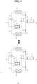
- an air conditioner 1 include a compressor 2, a switching valve 3, an outdoor heat exchanger 4, an indoor heat exchanger 5, a expansion valve Va and Vb, and a gas-liquid separator 10.
- the air conditioner 1 may include an injection valve Vi.
- the compressor 2 compresses the refrigerant introduced from an accumulator (not shown) and discharges a high-temperature and high-pressure refrigerant. Meanwhile, a first pipe P1 may be installed between the compressor 2 and the switching valve 3 to provide a flow path for refrigerant ranging from the compressor 2 to the switching valve 3.
- the switching valve 3 may receive a refrigerant which is discharged from the compressor 2 and passed through a first pipe P1.
- the switching valve 3 may guide the refrigerant introduced through the first pipe P1 to the outdoor heat exchanger 4 or the indoor heat exchanger 5 selectively.
- the switching valve 3 may be a four-way valve.
- a seventh pipe P7 may be installed between the switching valve 3 and the compressor 2 to provide a flow path for refrigerant ranging from the switching valve 3 to the compressor 2.
- the accumulator may be installed in the seventh pipe P7 to provide a vapor refrigerant to the compressor 2.
- the outdoor heat exchanger 4 may heat-exchange the refrigerant and outdoor air.
- the direction of heat transfer between the refrigerant and outdoor air in the outdoor heat exchanger 4 may differ depending on the operation mode of the air conditioner, that is, depending on whether it is a cooling operation or a heating operation.
- An outdoor fan 4a is disposed in one side of the outdoor heat exchanger 4 to adjust the amount of air provided to the outdoor heat exchanger 4.
- the outdoor fan 4a may be driven by an electric motor for outdoor fan.
- a second pipe P2 may be installed between the switching valve 3 and the outdoor heat exchanger 4 to provide a flow path for refrigerant connecting the switching valve 3 and the outdoor heat exchanger 4.
- the indoor heat exchanger 5 may heat-exchange the refrigerant and heat transfer medium.
- the direction of heat transfer between the refrigerant and the heat transfer medium in the indoor heat exchanger 5 may differ depending on the operation mode of the air conditioner, that is, depending on whether it is a cooling operation or a heating operation.
- a sixth pipe P6 may be installed between the switching valve 3 and the indoor heat exchanger 5 to provide a flow path for refrigerant connecting the switching valve 3 and the indoor heat exchanger 5.
- the heat transfer medium is indoor air, and heat exchange may be performed between the refrigerant and the indoor air in the indoor heat exchanger 5.
- an indoor fan 5a is disposed in one side of the indoor heat exchanger 5 to adjust the amount of air provided to the indoor heat exchanger 5.
- the indoor fan 5a may be driven by an electric motor for indoor fan.
- the heat transfer medium is water
- heat exchange may be performed between the refrigerant and water in the indoor heat exchanger 5.
- the water that has passed through the indoor heat exchanger 5 may be supplied to a radiator (not shown) installed indoors or a pipe installed in the floor to cool or heat an indoor space, or may be used to supply hot or cold water to the room by heating or cooling the water stored in a hot water tank.
- the indoor heat exchanger 5 may be a plate heat exchanger provided with a plurality of heat transfer plates stacked on each other.
- the refrigerant and water may flow through a flow path formed between a plurality of heat transfer plates, and may exchange heat with each other in a non-contact manner.
- the air conditioner may be referred to as an air-to-water heat pump (AWHP).
- the first expansion valve Va and the second expansion valve Vb may be installed between the outdoor heat exchanger 4 and the indoor heat exchanger 5.
- the first expansion valve Va may be installed in a third pipe P3 facing the second pipe P2, across the outdoor heat exchanger 4.
- the second expansion valve Vb may be installed in a fifth pipe P5 facing a sixth pipe P6, across the indoor heat exchanger 5.
- the first expansion valve Va and the second expansion valve Vb may expand the refrigerant supplied from one of the outdoor heat exchanger 4 and the indoor heat exchanger 5 at a low temperature and low pressure.
- the gas-liquid separator 10 may receive the refrigerant expanded from the first expansion valve Va or the second expansion valve Vb. To this end, a part of the third pipe P3 and a part of the fifth pipe P5 may be installed in the gas-liquid separator 10.
- the third pipe P3 may provide a flow path of refrigerant connecting the outdoor heat exchanger 4 and the gas-liquid separator 10
- the fifth pipe P5 may provide a flow path of refrigerant connecting the indoor heat exchanger 5 and the gas-liquid separator 10.
- the gas-liquid separator 10 may separate and discharge the refrigerant introduced through the third pipe P3 or the fifth pipe P5 into a vapor refrigerant and a liquid refrigerant.
- the fourth pipe P4 may provide a flow path for refrigerant connecting the gas-liquid separator 10 and the medium pressure stage of the compressor 2 described later.
- the injection valve Vi is installed in a fourth pipe P4 to open and close the flow path of the fourth pipe P4.
- the compressor 2 may compress the refrigerant introduced from the accumulator and discharge the compressed refrigerant in a high temperature and high pressure state.
- the refrigerant discharged from the compressor 2 may flow into the outdoor heat exchanger 4 through the first pipe P1, the switching valve 3, and the second pipe P2 sequentially.
- the refrigerant may be condensed.
- the outdoor heat exchanger 4 may serve as a condenser.
- the refrigerant which is condensed while passing through the outdoor heat exchanger 4 may pass through the first expansion valve Va in the third pipe P3 and may be expanded to a range corresponding to the medium pressure stage of the compressor 2.
- the medium pressure stage of the compressor 2 may be understood as a pressure (i.e. low pressure) formed between the pressure of the refrigerant flowing into the compressor 2 and the pressure (i.e. high pressure) of the refrigerant discharged from the compressor 2.
- the first expansion valve Va may be an electronic expansion valve (EEV) capable of adjusting the opening degree of the flow path of the third pipe P3.
- EOV electronic expansion valve
- the refrigerant which is expanded while passing through the first expansion valve Va may flow into the gas-liquid separator 10 in a two-phase state.
- the gas-liquid separator 10 may separate and discharge the two-phase refrigerants that flowed to the gas-liquid separator 10 through the third pipe P3 into a vapor refrigerant and a liquid refrigerant.
- the vapor refrigerant separated by the gas-liquid separator 10 may flow into the medium pressure stage of the compressor 2 through the fourth pipe P4.
- the injection valve Vi may be a solenoid valve or an EEV that opens and closes the fourth pipe P4.
- the liquid refrigerant separated by the gas-liquid separator 10 may flow into the fifth pipe P5.
- the liquid refrigerant flowed to the fifth pipe P5 may pass through the second expansion valve Vb and expand to a range corresponding to the low pressure stage of the compressor 2.
- the second expansion valve Vb may be an EEV.
- the refrigerant which is expanded while passing through the second expansion valve Vb may flow to the indoor heat exchanger 5 through the fifth pipe P5.
- the refrigerant may be evaporated.
- the indoor heat exchanger 5 may serve as an evaporator.
- the temperature of the indoor air is lowered, so that the indoor space may be cooled.
- the refrigerant which is evaporated while passing through the indoor heat exchanger 5 may flow into the compressor 2 through a sixth pipe P6, the switching valve 3, and a seventh pipe P7 sequentially, so that a refrigerant cycle for cooling operation of the above-described air conditioner may be completed.
- the compressor 2 may compress the refrigerant flowed from the accumulator and discharges the compressed refrigerant in a high temperature and high pressure state.
- the refrigerant discharged from the compressor 2 may flow to the indoor heat exchanger 5 through the first pipe P1, the switching valve 3, and the sixth pipe P6 sequentially.
- the refrigerant may be condensed.
- the indoor heat exchanger 5 may serve as a condenser.
- the temperature of the indoor air is increased, so that the indoor space may be cooled.
- the refrigerant which is condensed while passing through the indoor heat exchanger 5 may pass through the second expansion valve Vb in the fifth pipe P5 and may be expanded to a range corresponding to the medium pressure stage of the compressor 2.
- the medium pressure stage of the compressor 2 may be understood as a pressure formed between the pressure (i.e. low pressure) of the refrigerant flowing into the compressor 2 and the pressure (i.e.
- the second expansion valve Vb may be an electronic expansion valve (EEV) capable of adjusting the opening degree of the flow path of the fifth pipe P5.
- EOV electronic expansion valve
- the gas-liquid separator 10 may separate and discharge the two-phase refrigerants flowed to the gas-liquid separator 10 through the fifth pipe P5 into a vapor refrigerant and a liquid refrigerant.
- the vapor refrigerant separated in the gas-liquid separator 10 may flow into the medium pressure stage of the compressor 2 through the fourth pipe P4.
- the injection valve Vi may be a solenoid valve or an EEV that opens and closes the fourth pipe P4.
- the liquid refrigerant separated in the gas-liquid separator 10 may flow into the third pipe P3.
- the liquid refrigerant flowed to the third pipe P3 may pass through the first expansion valve Va and may expand to a range corresponding to the low pressure stage of the compressor 2.
- the first expansion valve Va may be an EEV.
- the refrigerant which is expanded while passing through the first expansion valve Va may flow to the outdoor heat exchanger 4 through the third pipe P3.
- the refrigerant may be evaporated.
- the outdoor heat exchanger 4 may serve as an evaporator.
- the refrigerant which is evaporated while passing through the outdoor heat exchanger 4 may flow into the compressor 2 through the second pipe P2, the switching valve 3, and the seventh pipe P7 sequentially, so that a refrigerant cycle for the above-described heating operation of air conditioner can be completed.
- the fourth pipe P4' may provide a flow path for refrigerant connecting the gas-liquid separator 10 and a seventh pipe P7.
- the injection valve Vi may be installed in the fourth pipe P4 ⁇ to open and close the flow path of the fourth pipe P4'. Accordingly, the vapor refrigerant separated in the gas-liquid separator 10 may flow into the low pressure stage of the compressor 2 through the fourth pipe P4'.
- the refrigerant which is condensed while passing through the outdoor heat exchanger 4 may be expanded to a range corresponding to the low pressure stage of the compressor 2 in the first expansion valve Va.
- the liquid refrigerant separated in the gas-liquid separator 10 is provided to the indoor heat exchanger 5 through the fifth pipe P5, and the second expansion valve Vb may completely open the flow path of the fifth pipe P5.
- the vapor refrigerant separated in the gas-liquid separator 10 may flow to the seventh pipe P7 through the fourth pipe P4' and may be provided to a suction end of the compressor 2.
- the refrigerant which is condensed while passing through the indoor heat exchanger 5 may be expanded to a range corresponding to the low pressure stage of the compressor 2 in the second expansion valve Vb.
- the liquid refrigerant separated in the gas-liquid separator 10 is provided to the outdoor heat exchanger 4 through the third pipe P3, and the first expansion valve Va may completely open the flow path of third pipe P3.
- the vapor refrigerant separated in the gas-liquid separator 10 may flow to the seventh pipe P7 through the fourth pipe P4' and may be provided to a suction end of the compressor 2.
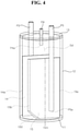
- the gas-liquid separator 10 may include a base 11, a housing 12, a cap 13, a first partition wall 14 and a second partition wall 15. Meanwhile, according to the embodiment, the gas-liquid separator 10 may further include a third partition wall located between the first partition wall 14 and the second partition wall 15, in addition to the first partition wall 14 and the second partition wall 15 described later.
- the base 11 may form the lower surface of the gas-liquid separator 10.
- the base 11 is formed in a circular plate shape as a whole, and the housing 12, the first partition wall 14, and the second partition wall 15 may be installed.
- the housing 12 may form a side surface of the gas-liquid separator 10.
- the housing 12 is formed in a cylindrical shape as a whole, and may accommodate the first partition wall 14 and the second partition wall 15 therein. Meanwhile, the lower end of the housing 12 is in close contact with the base 11 to prevent the refrigerant from leaking from the inside of the housing to the outside.
- the cap 13 may form an upper surface of the gas-liquid separator 10.
- the cap 13 is formed in a circular plate shape as a whole, and a hole through which the third pipe P3, the fourth pipe P4, and the fifth pipe P5 passes may be formed. Meanwhile, the upper end of the housing 12 is in close contact with the cap 13 to prevent the refrigerant from leaking from the inside of the housing to the outside.
- the first partition wall 14 and the second partition wall 15 may be installed in an internal accommodation space of the housing 12.
- the first partition wall 14 and the second partition wall 15 may be spaced apart from each other at a certain interval d.
- the lower end of the first partition wall 14 and the lower end of the second partition wall 15 may be fixed on the base 11.
- the side surfaces of the first partition wall 14 and the side surface of the second partition wall 15 may be fixed to the inner surface of the housing 12.
- the upper end of the first partition wall 14 and the upper end of the second partition wall 15 may be spaced apart from the lower surface of the cap 13.
- first partition wall 14 and the second partition wall 15 may divide the internal accommodation space of the housing 12 in the horizontal direction into a first space Sa that is a space between the first partition wall 14 and the inner surface of the housing 12, a second space Sb that is a space between the first partition wall 14 and the second partition wall 15, and a third space Sc that is a space between the second partition wall 15 and the inner surface of the housing 12.
- a fourth space Sd may be formed between the lower surface of the cap 13 and the first and second partition walls 14 and 15.
- the third pipe P3 may be vertically connected to the upper side of the gas-liquid separator 10 through a hole in the cap 13, and may be disposed in the internal accommodation space of the housing 12.
- the third pipe P3 may be disposed in the fourth space Sd and in the first space Sa which is a space between the inner surface of the housing 12 and the first partition wall 14.
- a distal end P3a of the third pipe P3 may be spaced apart from the base 11 and may be adjacent to the upper surface of the base 11.
- the fourth pipe P4 may be vertically connected to the upper side of the gas-liquid separator 10 through a hole in the cap 13, and may be disposed in the internal accommodation space of the housing 12.
- the fourth pipe P4 may be disposed in the fourth space Sd.
- a distal end P4a of the fourth pipe P4 may be located between the first partition wall 14 and the second partition wall 15 in the horizontal direction.
- the distal end P4a of the fourth pipe P4 may be located in the fourth space Sd above the second space Sb which is a space between the first partition wall 14 and the second partition wall 15.
- the fifth pipe P5 may be vertically connected to the upper side of the gas-liquid separator 10 through a hole of the cap 13, and may be disposed in the internal accommodation space of the housing 12.
- the fifth pipe P5 may be disposed in the fourth space Sd and in the third space Sc which is a space between the inner surface of the housing 12 and the second partition wall 15.
- a distal end P5a of the fifth pipe P5 may be spaced apart from the base 11 and may be adjacent to the upper surface of the base 11.
- the first partition wall 14 and the second partition wall 15 may be formed in a plate shape as a whole.
- the lower surface of the first partition wall 14 may be fixed on the base 11. In the vertical direction, the height Ha of the first partition wall 14 may be smaller than the height Ht of the housing 12. Accordingly, the upper surface of the first partition wall 14 may be located below the cap 13.
- the first partition wall 14 may include a first surface 14a that contacts the inner surface of the housing 12 in the horizontal direction, and a second surface 14b that faces the first surface 14a and contacts the inner surface of the housing 12.
- a point where the upper surface, the lower surface, the first surface 14a, and the second surface 14b of the first partition wall 14 meet each other may be referred to as a corner.
- a point where the upper surface of the first partition wall 14 and the first surface 14a meet may be referred to as a first corner
- a point where the upper surface of the first partition wall 14 and the second surface 14b meet may be referred to as a second corner
- a point where the lower surface of the first partition wall 14 and the first surface 14a meet may be referred to as a third corner
- a point where the lower surface of the first partition wall 14 and the second surface 14b meet may be referred to as a fourth corner.
- a first opening 140 may be formed by cutting-out a part of the outer surface of the first partition wall 14.
- the first opening 140 may be formed by cutting-out the fourth corner of the first partition wall 14.
- one end of the first opening 140 may be connected to the lower surface of the first partition wall 14 and the other end may be connected to the second surface 14b.
- the first opening 140 may extend in a direction crossing the upper surface of the base 11. In this case, the first opening 140 may form an acute angle with respect to the upper surface of the base 11. Accordingly, the first space Sa and the second space Sb may communicate with each other through the first opening 140.
- the distal end P3a of the third pipe P3 may be located closer to the first surface 14a than the first opening 140 or the second surface 14b.
- the distal end P3a of the third pipe P3 may be located between a virtual first vertical line 14m (not shown) that passes through the center of the first partition wall 14 and extends in the vertical direction and the first surface 14a, and the first opening 140 may be located between the first vertical line 14m and the second surface 14b.
- the lower surface of the second partition wall 15 may be fixed on the base 11. In the vertical direction, the height Ha of the second partition wall 15 may be smaller than the height Ht of the housing 12. Accordingly, the upper surface of the second partition wall 15 may be located below the cap 13.
- the second partition wall 15 may include a first surface 15a that contacts the inner surface of the housing 12 in the horizontal direction, and a second surface 15b that faces the first surface 15a and contacts the inner surface of the housing 12.
- a point where the upper surface, the lower surface, the first surface 15a, and the second surface 15b of the second partition wall 15 meet each other may be referred to as a corner.
- a point where the upper surface of the second partition wall 15 and the first surface 15a meet may be referred to as a first corner
- a point where the upper surface of the second partition wall 15 and the second surface 15b meet may be referred to as a second corner
- a point where the lower surface of the second partition wall 15 and the first surface 15a meet may be referred to as a third corner
- a point where the lower surface of the second partition wall 15 and the second surface 15b meet may be referred to as a fourth corner.
- a second opening 150 may be formed by cutting-out a part of the outer surface of the second partition wall 15.
- the second opening 150 may be formed by cutting-out the fourth corner of the second partition wall 15.
- one end of the second opening 150 may be connected to the lower surface of the second partition wall 15 and the other end may be connected to the second surface 15b.
- the second opening 150 may extend in a direction crossing the upper surface of the base 11.
- the second opening 150 may form an acute angle with respect to the upper surface of the base 11.
- the third space Sc and the second space Sb may communicate with each other through the second opening 150.
- a direction in which the first opening 140 extends and a direction in which the second opening 150 extends may cross each other.
- a distal end P5a of the fifth pipe P5 may be located closer to the first surface 15a than the second opening 150 or the second surface 15b.
- the distal end P5a of the fifth pipe P5 may be located between a virtual second vertical line 15m (not shown) that passes through the center of the second partition wall 15 and extends in the vertical direction and the first surface 15a, and the second opening 150 may be located between the first vertical line 15m and the second surface 15b.
- a first direction from the first surface 14a to the second surface 14b of the first partition wall 14 and a second direction from the first surface 15a to the second surface 15b of the second partition wall 15 may be opposite to each other.
- the second opening 150 may be formed in a portion that is farthest from the first opening 140 among the lower end of the second partition wall 15.
- the first opening 140 and the second opening 150 may face each other, across a circle center of the inner circumferential surface of the housing 12.
- the inner radius R of the housing 12 may be defined based on the circle center.
- the refrigerant which is expanded while passing through the first expansion valve Va may flow into the first space Sa of the housing 12 in a two-phase state through the third pipe P3.
- the third pipe P3 may be referred to as a refrigerant inflow pipe.
- the two-phase refrigerants flowed to the first space Sa may flow along the inner surface of the housing 12, the first partition wall 14, and the second partition wall 15, and may be separated into a vapor refrigerant and a liquid refrigerant.
- the fourth pipe P4 may be referred to as a bypass pipe.
- the distal end P3a of the third pipe P3 is relatively far apart from the first opening 140, it is possible to prevent the vapor refrigerant from flowing into the first opening 140.
- the remaining refrigerant excluding the vapor refrigerant flowed to the fourth pipe P4 may flow into the second space Sb from the first space Sa through the first opening 140, and may flow into the third space Sc from the second space Sb through the second opening 150 (refer to reference numeral Fa).
- the vapor refrigerant included in the remaining refrigerant during the above-described refrigerant flow process may move upward toward the fourth space Sd, and may flow into the distal end P4a of the fourth pipe P4.
- the liquid refrigerant flowed to the third space Sc may flow into the distal end P5a of the fifth pipe P5, and pass through the above-described second expansion valve Vb, the indoor heat exchanger 5, and the like.
- the fifth pipe P5 may be referred to as a refrigerant discharge pipe.
- the refrigerant which is expanded while passing through the second expansion valve Vb may flow into the third space Sc of the housing 12 through the fifth pipe P5 in a two-phase state.
- the fifth pipe P5 may be referred to as a refrigerant inflow pipe.
- the two-phase refrigerant flowed to the third space Sc may flow along the inner surface of the housing 12, the second partition wall 15, and the first partition wall 14, and may be separated into a vapor refrigerant and a liquid refrigerant.
- the fourth pipe P4 may be referred to as a bypass pipe.
- the vapor refrigerant may be prevented from flowing into the second opening 150.
- the remaining refrigerant excluding the vapor refrigerant flowed to the fourth pipe P4, among the two phase refrigerants discharged from the distal end P5a of the fifth pipe P5, may flow into the second space Sb from the third space Sc through the second opening 150, and may flow into the first space Sa from the second space Sb through the first opening 140.
- the vapor refrigerant included in the remaining refrigerant during the above-described refrigerant flow process may move upward toward the fourth space Sd, and may flow into the distal end P4a of the fourth pipe P4.
- the liquid refrigerant flowed to the first space Sa may flow into the distal end P3a of the third pipe P3, and may pass through the above-described first expansion valve Va, the outdoor heat exchanger 4, and the like.
- the third pipe P3 may be referred to as a refrigerant discharge pipe.
- the gas-liquid separation efficiency in the gas-liquid separator 10 is increased, and the reliability of the compressor can be obtained by preventing the liquid refrigerant from being discharged through the fourth pipe P4.
- the third pipe P3' and the fifth pipe P5' are horizontally connected to the side surface of the gas-liquid separator 10 through a hole formed in the side surface of the gas-liquid separator 10, and may be disposed in the internal accommodation space of the housing 12.
- the third pipe P3' may be provided with a first expansion valve Va (see FIG. 1 ).
- the third pipe P3' may be disposed in the first space Sa which is a space between the inner surface of the housing 12 and the first partition wall 14.
- the distal end P3a' of the third pipe P3' may be spaced apart from the base 11 and may be adjacent to the upper surface of the base 11.
- the distal end P3a' of the third pipe P3' may be located closer to the first surface 14a than the first opening 140 or the second surface 14b.
- the distal end P3a' of the third pipe P3' is located between the virtual first vertical line 14m that extends in the vertical direction while passing through the center of the first partition wall 14 and the first surface 14a, and the first opening 140 may be located between the first vertical line 14m and the second surface 14b.
- the fifth pipe P5' may be provided with a second expansion valve Vb (see FIG. 1 ).
- the fifth pipe P5' may be disposed in the third space Sc which is a space between the inner surface of the housing 12 and the second partition wall 15.
- the distal end P5a' of the fifth pipe P5' may be spaced apart from the base 11 and may be adjacent to the upper surface of the base 11.
- the distal end P5a' of the fifth pipe P5' may be located closer to the first surface 15a than the second opening 150 or the second surface 15b.
- the distal end P5a' of the fifth pipe P5' may be located between the virtual second vertical line 15m (not shown) that extends in the vertical direction while passing through the center of the second partition wall 15 and the first surface 15a, and the second opening 150 may be located between the second vertical line 15m and the second surface 15b.
- the refrigerant which is expanded while passing through the first expansion valve Va may flow into the first space Sa of the housing 12 through the third pipe P3' in a two-phase state.
- the third pipe P3' may be referred to as a refrigerant inflow pipe.
- the two-phase refrigerant flowed to the first space Sa may flow along the inner surface of the housing 12, the first partition wall 14, and the second partition wall 15, and may be separated into a vapor refrigerant and a liquid refrigerant.
- the fourth pipe P4 may be referred to as a bypass pipe.
- the vapor refrigerant may be prevented from flowing to the first opening 140.
- the remaining refrigerant excluding the vapor refrigerant flowed to the fourth pipe P4 may flow into the second space Sb from the first space Sa through the first opening 140, and may flow into the third space Sc from the second space Sb through the second opening 150 (refer to reference numeral Fb).
- the vapor refrigerant included in the remaining refrigerant during the above-described refrigerant flow process may move upward toward the fourth space Sd, and may flow into the distal end P4a of the fourth pipe P4.
- the liquid refrigerant flowed to the third space Sc may flow into the distal end P5a' of the fifth pipe P5', and pass through the above-described second expansion valve Vb, the indoor heat exchanger 5, and the like.
- the fifth pipe P5' may be referred to as a refrigerant discharge pipe.
- the refrigerant which is expanded while passing through the second expansion valve Vb may flow into the third space Sc of the housing 12 through the fifth pipe P5' in a two-phase state.
- the fifth pipe P5' may be referred to as a refrigerant inflow pipe.
- the two-phase refrigerant flowed to the third space Sc may flow along the inner surface of the housing 12, the second partition wall 15, and the first partition wall 14, and may be separated into a vapor refrigerant and a liquid refrigerant.
- the vapor refrigerant may move upward from the third space Sc toward the fourth space Sd, and may flow into the distal end P4a of the fourth pipe P4 and be provided to the compressor 2 (see FIG. 1 ).
- the fourth pipe P4 may be referred to as a bypass pipe.
- the vapor refrigerant may be prevented from flowing into the second opening 150.
- the remaining refrigerant excluding the vapor refrigerant flowed to the fourth pipe P4, among the two phase refrigerants discharged from the distal end P5a of the fifth pipe P5, may flow into the second space Sb from the third space Sc through the second opening 150, and may flow into the first space Sa from the second space Sb through the first opening 140.
- the vapor refrigerant included in the remaining refrigerant during the above-described refrigerant flow process may move upward toward the fourth space Sd, and may flow into the distal end P4a of the fourth pipe P4.
- the liquid refrigerant flowed to the first space Sa may flow into the distal end P3a' of the third pipe P3', and may pass through the above-described first expansion valve Va, the outdoor heat exchanger 4, and the like.
- the third pipe P3' may be referred to as a refrigerant discharge pipe.
- the gas-liquid separation efficiency in the gas-liquid separator 10 is increased, and the reliability of the compressor can be obtained by preventing the liquid refrigerant from being discharged through the fourth pipe P4.
- the gas-liquid separator 10 may include a first partition wall 16 and a second partition wall 17.
- the first partition wall 16 and the second partition wall 17 may be installed in the internal accommodation space of the housing 12.
- the first partition wall 16 and the second partition wall 17 may be spaced apart from each other.
- the lower end of the first partition wall 16 and the lower end of the second partition wall 17 may be fixed on the base 11.
- the side surface of the first partition wall 16 and the side surface of the second partition wall 17 may be fixed to the inner surface of the housing 12.
- the upper end of the first partition wall 16 and the upper end of the second partition wall 17 may be spaced apart from the lower surface of the cap 13.
- the first partition wall 16 and the second partition wall 17 may divide the internal accommodation space of the housing 12 in the horizontal direction into a first space Se that is a space between the first partition wall 16 and the inner surface of the housing 12, a second space Sf that is a space between the first partition wall 16 and the second partition wall 17, and a third space Sg that is a space between the second partition wall 17 and the inner surface of the housing 12.
- a fourth space Sh may be formed between the lower surface of the cap 13 and the first and second partition walls 16 and 17.
- the first partition wall 16 and the second partition wall 17 may be formed as a whole in a plate shape that is bent at least once in the radial direction of the housing 12.
- the lower surface of the first partition wall 16 may be fixed on the base 11. In the vertical direction, the height Hc of the first partition wall 16 may be smaller than the height Ht of the housing 12. Accordingly, the upper surface of the first partition wall 16 may be located below the cap 13.
- the first partition wall 16 may include a first plate 161 and a second plate 162.
- the first plate 161 and the second plate 162 may be coupled to each other along a virtual first vertical line 16m (not shown) extending in the vertical direction while passing through the center of the first partition wall 16.
- Each of the first plate 161 and the second plate 162 may be formed flat.
- the second plate 162 may be inclined at a certain angle (theta a) with respect to the first plate 161.
- theta a may be an obtuse angle.
- the first partition wall 16 may include a first surface 16a that contacts the inner surface of the housing 12 in the horizontal direction, and a second surface 16b that faces the first surface 16a and contacts the inner surface of the housing 12.
- the first surface 16a may be provided on the first plate 161 and the second surface 16b may be provided on the second plate 162.
- a point where the upper surface, the lower surface, the first surface 16a, and the second surface 16b of the first partition wall 16 meet each other may be referred to as a corner.
- a point where the upper surface of the first partition wall 16 and the first surface 16a meet may be referred to as a first corner
- a point where the upper surface of the first partition wall 16 and the second surface 16b meet may be referred to as a second corner
- a point where the lower surface of the first partition wall 16 and the first surface 16a meet may be referred to as a third corner
- a point where the lower surface of the first partition wall 16 and the second surface 16b meet may be referred to as a fourth corner.
- the first corner and the third corner may be provided in the first plate 161 and the second corner and the fourth corner may be provided in the second plate 162.
- a first opening 160 may be formed by cutting-out a part of the outer surface of the first partition wall 16.
- the first opening 160 may be formed by cutting-out the fourth corner of the first partition wall 16.
- one end of the first opening 160 may be connected to the lower surface of the first partition wall 16 and the other end may be connected to the second surface 16b.
- the first opening 160 may extend in a direction crossing the upper surface of the base 11. In this case, the first opening 160 may form an acute angle with respect to the upper surface of the base 11. Accordingly, the first space Se and the second space Sf may communicate with each other through the first opening 160.
- the distal end P3a of the third pipe P3 may be located closer to the first surface 16a than the first opening 160 or the second surface 16b. In other words, the distal end P3a of the third pipe P3 may be located closer to the first plate 161 than the second plate 162.
- the lower surface of the second partition wall 17 may be fixed on the base 11. In the vertical direction, the height Ha of the second partition wall 17 may be smaller than the height Ht of the housing 12. Accordingly, the upper surface of the second partition wall 17 may be located below the cap 13.
- the second partition wall 17 may include a first plate 171 and a second plate 172.
- the first plate 171 and the second plate 172 may be coupled to each other along a virtual second vertical line 17m extending in the vertical direction while passing through the center of the second partition wall 17.
- Each of the first plate 171 and the second plate 172 may be formed flat.
- the second plate 172 may be inclined at a certain angle (theta b) with respect to the first plate 171.
- theta b may be an obtuse angle.
- the second partition wall 17 may include a first surface 17a that contacts the inner surface of the housing 12 in the horizontal direction, and a second surface 17b that faces the first surface 17a and contacts the inner surface of the housing 12.
- the first surface 17a may be provided on the first plate 171 and the second surface 17b may be provided on the second plate 172.
- a point where the upper surface, the lower surface, the first surface 17a, and the second surface 17b of the second partition wall 17 meet each other may be referred to as a corner.
- a point where the upper surface of the second partition wall 17 and the first surface 17a meet may be referred to as a first corner
- a point where the upper surface of the second partition wall 17 and the second surface 17b meet may be referred to as a second corner
- a point where the lower surface of the second partition wall 17 and the first surface 17a meet may be referred to as a third corner
- a point where the lower surface of the second partition wall 17 and the second surface 17b meet may be referred to as a fourth corner.
- the first corner and the third corner may be provided in the first plate 171
- the second corner and the fourth corner may be provided in the second plate 172.
- a second opening 170 may be formed by cutting-out a part of the outer surface of the second partition wall 17.
- the second opening 170 may be formed by cutting-out the fourth corner of the second partition wall 17.
- one end of the second opening 170 may be connected to the lower surface of the second partition wall 17 and the other end may be connected to the second surface 17b.
- the second opening 170 may extend in a direction crossing the upper surface of the base 11.
- the second opening 170 may form an acute angle with respect to the upper surface of the base 11.
- the third space Sg and the second space Sf may communicate with each other through the second opening 170.
- a direction in which the first opening 160 extends and a direction in which the second opening 170 extends may cross each other.
- a distal end P5a of the fifth pipe P5 may be located closer to the first surface 17a than the second opening 170 or the second surface 17b. In other words, the distal end P5a of the fifth pipe P5 may be located closer to the first plate 171 than the second plate 172.
- a first direction from the first surface 16a toward the second surface 16b in the first partition wall 16 and a second direction from the first surface 17a toward the second surface 17b in the second partition wall 17 may be opposite to each other.
- the second opening 170 may be formed in a portion that is farthest from the first opening 160 among the lower end of the second partition wall 17.
- the first opening 160 and the second opening 170 may face each other, across a circle center of the inner circumferential surface of the housing 12.
- the inner radius R of the housing 12 may be defined based on the circle center.
- the refrigerant which is expanded while passing through the first expansion valve Va may flow into the first space Sa of the housing 12 through the third pipe P3 in a two-phase state.
- the third pipe P3 may be referred to as a refrigerant inflow pipe.
- the two-phase refrigerants flowed to the first space Sa may flow along the inner surface of the housing 12, the first partition wall 16, and the second partition wall 17, and may be separated into a vapor refrigerant and a liquid refrigerant.
- the vapor refrigerant may move upward from the first space Se toward the fourth space Sh, and may flow into the distal end P4a of the fourth pipe P4 and be provided to the compressor 2 (see FIG. 1 ).
- the fourth pipe P4 may be referred to as a bypass pipe.
- the vapor refrigerant may be prevented from flowing into the first opening 160.
- the liquid refrigerant among the two-phase refrigerant discharged from the distal end P3a of the third pipe P3, may be prevented from flowing into the distal end P4a of the fourth pipe P4 through the fourth space Sh.
- the remaining refrigerant excluding the vapor refrigerant flowed to the fourth pipe P4 may flow into the second space Sf from the first space Se through the first opening 160, and may flow into the third space Sg from the second space Sf through the second opening 170 (refer to reference numeral Fc).
- the vapor refrigerant included in the remaining refrigerant during the above-described refrigerant flow process may move upward toward the fourth space Sd, and may flow into the distal end P4a of the fourth pipe P4.
- the liquid refrigerant flowed to the third space Sg may flow into the distal end P5a of the fifth pipe P5, and may pass through the above-described second expansion valve Vb, the indoor heat exchanger 5, and the like.
- the fifth pipe P5 may be referred to as a refrigerant discharge pipe.
- the refrigerant which is expanded while passing through the second expansion valve Vb may flow into the third space Sc of the housing 12 through the fifth pipe P5 in a two-phase state.
- the fifth pipe P5 may be referred to as a refrigerant inflow pipe.
- the two-phase refrigerant flowed to the third space Sg may flow along the inner surface of the housing 12, the second partition wall 17, and the first partition wall 16, and may be separated into a vapor refrigerant and a liquid refrigerant.
- the fourth pipe P4 may be referred to as a bypass pipe.
- the vapor refrigerant may be prevented from flowing into the second opening 170.
- the liquid refrigerant may be prevented from flowing into the distal end P4a of the fourth pipe P4 through the fourth space Sh.
- the remaining refrigerant excluding the vapor refrigerant flowed to the fourth pipe P4, among the two phase refrigerants discharged from the distal end P5a of the fifth pipe P5, may flow into the second space Sf through the second opening 170 from the third space Sg, and may flow into the first space Se through the first opening 160 from the second space Sf.
- the vapor refrigerant included in the remaining refrigerant during the above-described refrigerant flow process may move upward toward the fourth space Sh, and may flow into the distal end P4a of the fourth pipe P4.
- the liquid refrigerant flowed to the first space Se may flow into the distal end P3a of the third pipe P3, and may pass through the above-described first expansion valve Va, the outdoor heat exchanger 4, and the like.
- the third pipe P3 may be referred to as a refrigerant discharge pipe.
- the gas-liquid separation efficiency in the gas-liquid separator 10 is increased, and the reliability of the compressor can be obtained by preventing the liquid refrigerant from being discharged through the fourth pipe P4.
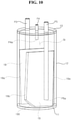
- the gas-liquid separator 10 may include a first partition wall 18 and a second partition wall 19.
- the first partition wall 18 and the second partition wall 19 may be installed in the internal accommodation space of the housing 12.
- the first partition wall 18 and the second partition wall 19 may be spaced apart from each other.
- the lower end of the first partition wall 18 and the lower end of the second partition wall 19 may be fixed on the base 11.
- the side surface of the first partition wall 18 and the side surface of the second partition wall 19 may be fixed to the inner surface of the housing 12.
- the upper end of the first partition wall 18 and the upper end of the second partition wall 19 may be spaced apart from the lower surface of the cap 13.
- the first partition wall 18 and the second partition wall 19 may divide the internal accommodation space of the housing 12 in the horizontal direction into a first space Si that is a space between the first partition wall 18 and the inner surface of the housing 12, a second space Sj that is a space between the first partition wall 18 and the second partition wall 19, and a third space Sk that is a space between the second partition wall 19 and the inner surface of the housing 12.
- a fourth space Sl may be formed between the lower surface of the cap 13 and the first and second partition walls 16 and 17.
- the first partition wall 18 and the second partition wall 19 may be formed as a whole in a plate shape, and may be disposed to be inclined with respect to the base 11.
- the lower surface of the first partition wall 18 may be fixed on the base 11. In the vertical direction, the height Hc of the first partition wall 18 may be smaller than the height Ht of the housing 12. Accordingly, the upper surface of the first partition wall 18 may be located below the cap 13.
- the first partition wall 18 may extend long in a direction crossing the base 11.
- the first partition wall 18 may be inclined at a certain angle (theta c) with respect to the base 11.
- theta c may be an acute angle.
- the lower end of the first partition wall 18 is spaced apart from the inner surface of the housing 12, and the upper end of the first partition wall 18 may contact the inner surface of the housing 12.
- the first partition wall 18 may include a first surface 18a that contacts the inner surface of the housing 12 in the horizontal direction, and a second surface 18b that faces the first surface 18a and contacts the inner surface of the housing 12.
- a point where the upper surface, the lower surface, the first surface 18a, and the second surface 18b of the first partition wall 18 meet each other may be referred to as a corner.
- a point where the upper surface of the first partition wall 18 and the first surface 18a meet may be referred to as a first corner
- a point where the upper surface of the first partition wall 18 and the second surface 18b meet may be referred to as a second corner
- a point where the lower surface of the first partition wall 18 and the first surface 18a meet may be referred to as a third corner
- a point where the lower surface of the first partition wall 18 and the second surface 18b meet may be referred to as a fourth corner.
- a first opening 180 may be formed by cutting-out a part of the outer surface of the first partition wall 18.
- the first opening 180 may be formed by cutting-out the fourth corner of the first partition wall 18.
- one end of the first opening 180 may be connected to the lower surface of the first partition wall 18 and the other end may be connected to the second surface 18b.
- the first opening 180 may extend in a direction crossing the upper surface of the base 11.
- the first opening 180 may form an acute angle with respect to the upper surface of the base 11. Accordingly, the first space Si and the second space Sj may communicate with each other through the first opening 180.
- the distal end P3a of the third pipe P3 may be located closer to the first surface 18a than the first opening 180 or the second surface 18b.
- the distal end P3a of the third pipe P3 may be located between the first virtual line 18m extending in the vertical direction while passing through the center of the first partition wall 18 and the first surface 18a, and the first opening 180 may be located between the first vertical line 18m and the second surface 18b.
- the lower surface of the second partition wall 19 may be fixed on the base 11. In the vertical direction, the height Ha of the second partition wall 19 may be smaller than the height Ht of the housing 12. Accordingly, the upper surface of the second partition wall 19 may be located below the cap 13.
- the second partition wall 19 may extend long in a direction crossing the base 11.
- the second partition wall 19 may be inclined at a certain angle (theta d) with respect to the base 11.
- theta d may be an acute angle.
- the lower end of the second partition wall 19 is spaced apart from the inner surface of the housing 12, and the upper end of the second partition wall 19 may contact the inner surface of the housing 12.
- the second partition wall 19 may include a first surface 19a that contacts the inner surface of the housing 12 in the horizontal direction, and a second surface 19b that faces the first surface 19a and contacts the inner surface of the housing 12.
- a point where the upper surface, the lower surface, the first surface 19a, and the second surface 19b of the second partition wall 19 meet each other may be referred to as a corner.
- a point where the upper surface of the second partition wall 19 and the first surface 19a meet may be referred to as a first corner
- a point where the upper surface of the second partition wall 19 and the second surface 19b meet may be referred to as a second corner
- a point where the lower surface of the second partition wall 19 and the first surface 19a meet may be referred to as a third corner
- a point where the lower surface of the second partition wall 19 and the second surface 19b meet may be referred to as a fourth corner.
- a second opening 190 may be formed by cutting-out a part of the outer surface of the second partition wall 19.
- the second opening 190 may be formed by cutting-out the fourth corner of the second partition wall 19.
- one end of the second opening 190 may be connected to the lower surface of the second partition wall 19 and the other end may be connected to the second surface 19b.
- the second opening 190 may extend in a direction crossing the upper surface of the base 11.
- the second opening 190 may form an acute angle with respect to the upper surface of the base 11.
- the third space Sk and the second space Sj may communicate with each other through the second opening 190.
- a direction in which the first opening 180 extends and a direction in which the second opening 190 extends may cross each other.
- a distal end P5a of the fifth pipe P5 may be located closer to the first surface 19a than the second opening 190 or the second surface 19b.
- the distal end P5a of the fifth pipe P5 may be located between a virtual second vertical line 19m extending in the vertical direction while passing through the center of the second partition wall 19 and the first surface 19a, and the second opening 190 may be located between the second vertical line 19m and the second surface 19b.
- a first direction from the first surface 18a of the first partition wall 18 toward the second surface 18b and a second direction from the first surface 19a of the second partition wall 19 toward the second surface 19b may be opposite to each other.
- the second opening 190 may be formed in a portion that is farthest from the first opening 180 among the lower end of the second partition wall 19.
- the first opening 180 and the second opening 190 may face each other, across a circle center of the inner circumferential surface of the housing 12.
- the inner radius R of the housing 12 may be defined based on the circle center.
- the refrigerant which is expanded while passing through the first expansion valve Va may flow into the first space Si of the housing 12 through the third pipe P3 in a two-phase state.
- the third pipe P3 may be referred to as a refrigerant inflow pipe.
- the two-phase refrigerants flowed to the first space Si may flow along the inner surface of the housing 12, the first partition wall 18, and the second partition wall 19, and may be separated into a vapor refrigerant and a liquid refrigerant.
- the vapor refrigerant may move upward from the first space Si toward the fourth space Sl, and may flow into the distal end P4a of the fourth pipe P4 and be provided to the compressor 2 (see FIG. 1 ).
- the fourth pipe P4 may be referred to as a bypass pipe.
- the vapor refrigerant may be prevented from flowing into the first opening 180.
- the liquid refrigerant among the two-phase refrigerant discharged from the distal end P3a of the third pipe P3, may be prevented from flowing into the distal end P4a of the fourth pipe P4 through the fourth space Sl.
- the remaining refrigerant excluding the vapor refrigerant flowed to the fourth pipe P4 may flow into the second space Sj from the first space Si through the first opening 180, and may flow into the third space Sk from the second space Sj through the second opening 190 (refer to reference numeral F1) .
- the vapor refrigerant included in the remaining refrigerant during the above-described refrigerant flow process may move upward toward the fourth space Sd, and may flow into the distal end P4a of the fourth pipe P4.
- the liquid refrigerant flowed to the third space Sk may flow into the distal end P5a of the fifth pipe P5, and may pass through the above-described second expansion valve Vb, the indoor heat exchanger 5, and the like.
- the fifth pipe P5 may be referred to as a refrigerant discharge pipe.
- the refrigerant which is expanded while passing through the second expansion valve Vb may flow into the third space Sk of the housing 12 through the fifth pipe P5 in a two-phase state.
- the fifth pipe P5 may be referred to as a refrigerant inflow pipe.
- the two-phase refrigerant flowed to the third space Sk may flow along the inner surface of the housing 12, the second partition wall 19, and the first partition wall 18, and may be separated into a vapor refrigerant and a liquid refrigerant.
- the fourth pipe P4 may be referred to as a bypass pipe.
- the vapor refrigerant may be prevented from flowing into the second opening 190.
- the liquid refrigerant among the two-phase refrigerant discharged from the distal end P5a of the fifth pipe P5, may be prevented from flowing into the distal end P4a of the fourth pipe P4 through the fourth space Sl.
- the remaining refrigerant excluding the vapor refrigerant flowed to the fourth pipe P4, among the two phase refrigerants discharged from the distal end P5a of the fifth pipe P5, may flow into the second space Sj through the second opening 190 from the third space Sk, and may flow into the first space Si through the first opening 180 from the second space Sj.
- the vapor refrigerant included in the remaining refrigerant during the above-described refrigerant flow process may move upward toward the fourth space Sl, and may flow into the distal end P4a of the fourth pipe P4.
- the liquid refrigerant flowed to the first space Si may flow into the distal end P3a of the third pipe P3, and may pass through the above-described first expansion valve Va, the outdoor heat exchanger 4, and the like.
- the third pipe P3 may be referred to as a refrigerant discharge pipe.
- the gas-liquid separation efficiency in the gas-liquid separator 10 is increased, and the reliability of the compressor can be obtained by preventing the liquid refrigerant from being discharged through the fourth pipe P4.
- an air conditioner including: a compressor which compresses a refrigerant; a condenser which condenses the refrigerant discharged from the compressor; an expansion valve which expands the refrigerant passing through the condenser; a gas-liquid separator, through which the refrigerant passed through the expansion valve is flowed, that separates and discharges the refrigerant flowed to the gas-liquid separator into a vapor refrigerant and a liquid refrigerant; an evaporator which evaporates the liquid refrigerant discharged from the gas-liquid separator; a refrigerant inflow pipe which connects the expansion valve and the gas-liquid separator; a bypass pipe which connects the gas-liquid separator and the compressor; and a refrigerant discharge pipe which connects the gas-liquid separator and the evaporator, wherein the gas-liquid separator includes: a housing in which the refrigerant inflow pipe, the bypass pipe, and the refrig
- the first partition wall and the second partition wall may divide a first space that is a space between the first partition wall and an inner surface of the housing, a second space that is a space between the first partition wall and the second partition wall, and a third space that is a space between the second partition wall and an inner surface of the housing, the refrigerant inflow pipe may be disposed in the first space, and the refrigerant discharge pipe may be disposed in the third space.
- the gas-liquid separator may further include a base to which a lower end of the first partition wall and a lower end of the second partition wall are fixed, the first opening may extend in a direction crossing an upper surface of the base, and may have one end connected to the lower end of the first partition wall, and the second opening may extend in a direction crossing the upper surface of the base, and may have one end connected to the lower end of the second partition wall.
- the refrigerant inflow pipe may be adjacent to the upper surface of the base and may have a distal end spaced apart from the first opening
- the refrigerant discharge pipe may be adjacent to the upper surface of the base and may have a distal end spaced apart from the second opening
- the one end of the first opening may be formed in a portion, among the lower end of the first partition wall, that is farthest from the lower end of the second partition wall
- the one end of the second opening may be formed in a portion, among the lower end of the second partition wall, that is farthest from the lower end of the first partition wall
- a direction in which the first opening extends and a direction in which the second opening extends may cross each other.
- the housing may be formed in a cylindrical shape, and each of the first partition wall and second partition wall may be bent at least once in a radial direction of the housing.
- each of the first partition wall and second partition wall may be disposed to be inclined while forming an acute angle with respect to the base.
- the gas-liquid separator may further include a cap which is spaced upward from the first partition wall and the second partition wall and is coupled to an upper end of the housing, the bypass pipe may be installed in the cap, and may have a distal end disposed in a fourth space located above the second space and below the cap.
- the bypass pipe may be connected in a vertical direction of the housing, and each of the refrigerant inflow pipe and the refrigerant discharge pipe may be connected to the housing in a vertical direction or in a horizontal direction.
- an air conditioner capable of increasing a separation rate of a vapor refrigerant and a liquid refrigerant by providing a partition wall in a gas-liquid separator.
- an air conditioner capable of obtaining the reliability of a compressor by preventing the liquid refrigerant from being discharged into a bypass pipe through which the vapor refrigerant separated in the gas-liquid separator flows.
- a configuration A described in a specific embodiment and/or drawing may be combined with a configuration B described in another embodiment and/or drawing. That is, even if the combination of configurations is not directly described, the combination is possible except for the case where the combination is described to be impossible.
Landscapes
- Engineering & Computer Science (AREA)
- Physics & Mathematics (AREA)
- Mechanical Engineering (AREA)
- Thermal Sciences (AREA)
- General Engineering & Computer Science (AREA)
- Chemical & Material Sciences (AREA)
- Analytical Chemistry (AREA)
- Power Engineering (AREA)
- Other Air-Conditioning Systems (AREA)
- Heat-Exchange Devices With Radiators And Conduit Assemblies (AREA)
- Compression-Type Refrigeration Machines With Reversible Cycles (AREA)
Abstract
Description
- This application claims the priority benefit of
Korean Patent Application No. 10-2020-0085992, filed on July 13, 2020 - The present disclosure relates to an air conditioner. In particular, the present disclosure relates to an air conditioner capable of increasing the separation rate of a vapor refrigerant and a liquid refrigerant by providing a partition wall in a gas-liquid separator.
- In general, an air conditioner refers to an apparatus that cools and heats a room through compression, condensation, expansion and evaporation processes of refrigerant. If an outdoor heat exchanger of the air conditioner serves as a condenser, whereas an indoor heat exchanger serves as an evaporator, the room may be cooled. On the other hand, if the outdoor heat exchanger of the air conditioner serves as an evaporator, whereas the indoor heat exchanger serves as a condenser, the room may be heated.
- A conventional air conditioner includes a gas-liquid separator that receives a refrigerant that has passed through an expansion valve and separates and discharges the received refrigerant into a vapor refrigerant and a liquid refrigerant. In this case, the vapor refrigerant separated in the gas-liquid separator is injected into a compressor, and the liquid refrigerant separated in the gas-liquid separator may be supplied to an evaporator.
- However, if the vapor refrigerant and the liquid refrigerant are not sufficiently separated in the gas-liquid separator, there is a problem in that the liquid refrigerant is injected into the compressor to cause damage to the compressor.
- Recently, a lot of researches have been conducted on a method of increasing the separation rate of vapor refrigerant and liquid refrigerant in a gas-liquid separator.
- An object of the present disclosure is to solve the above and other problems.
- Another object of the present disclosure is to provide an air conditioner capable of increasing a separation rate of a vapor refrigerant and a liquid refrigerant by providing a partition wall in a gas-liquid separator.
- Another object of the present disclosure is to provide an air conditioner capable of obtaining the reliability of a compressor by preventing the liquid refrigerant from being discharged into a bypass pipe through which the vapor refrigerant separated in the gas-liquid separator flows.
- Another object of the present disclosure is to provide various embodiments of structure of partition wall provided in the gas-liquid separator.
- In accordance with an aspect of the present invention, an air conditioner includes: a compressor which compresses a refrigerant; a condenser which condenses the refrigerant discharged from the compressor; an expansion valve which expands the refrigerant passing through the condenser; a gas-liquid separator, through which the refrigerant passed through the expansion valve is flowed, that separates and discharges the refrigerant flowed to the gas-liquid separator into a vapor refrigerant and a liquid refrigerant; an evaporator which evaporates the liquid refrigerant discharged from the gas-liquid separator; a refrigerant inflow pipe which connects the expansion valve and the gas-liquid separator; a bypass pipe which connects the gas-liquid separator and the compressor; and a refrigerant discharge pipe which connects the gas-liquid separator and the evaporator, wherein the gas-liquid separator includes: a housing in which the refrigerant inflow pipe, the bypass pipe, and the refrigerant discharge pipe are disposed; a first partition wall, which is disposed in an internal space of the housing and forms a first opening by cutting-out a part of an outer surface thereof, that is disposed adjacent to the refrigerant inflow pipe; and a second partition wall, which is spaced apart from the first partition wall and disposed in the internal space of the housing and forms a second opening by cutting-out a part of an outer surface thereof, that is disposed adjacent to the refrigerant discharge pipe.
- The above and other objects, features and advantages of the present invention will be more apparent from the following detailed description in conjunction with the accompanying drawings, in which:
-
FIG. 1 is a diagram that shows a configuration of an air conditioner capable of performing a switching between a cooling operation and a heating operation according to an embodiment of the present disclosure and shows a flow of a refrigerant, and explains an example in which a vapor refrigerant discharged from a gas-liquid separator is injected to a medium pressure stage of a compressor; -
FIG. 2 is a diagram that shows a configuration of an air conditioner capable of performing a switching between a cooling operation and a heating operation according to an embodiment of the present disclosure and shows a flow of a refrigerant, and explains an example in which a vapor refrigerant discharged from a gas-liquid separator is injected to a low pressure stage of a compressor; and -
FIGS. 3 to 10 are diagrams showing examples of a gas-liquid separator of an air conditioner according to embodiments of the present disclosure. - Description will now be given in detail according to exemplary embodiments disclosed herein, with reference to the accompanying drawings. For the sake of brief description with reference to the drawings, the same or equivalent components may be denoted by the same reference numbers, and description thereof will not be repeated. In general, suffixes such as "module" and "unit" may be used to refer to elements or components. Use of such suffixes herein is merely intended to facilitate description of the specification, and the suffixes do not have any special meaning or function. In the present disclosure, that which is well known to one of ordinary skill in the relevant art has generally been omitted for the sake of brevity. The accompanying drawings are used to assist in easy understanding of various technical features and it should be understood that the embodiments presented herein are not limited by the accompanying drawings. As such, the present disclosure should be construed to extend to any alterations, equivalents and substitutes in addition to those which are particularly set out in the accompanying drawings. It will be understood that although the terms first, second, etc. may be used herein to describe various elements, these elements should not be limited by these terms. These terms are only used to distinguish one element from another. It will be understood that when an element is referred to as being "connected with" another element, there may be intervening elements present. In contrast, it will be understood that when an element is referred to as being "directly connected with" another element, there are no intervening elements present. A singular representation may include a plural representation unless context clearly indicates otherwise. Terms such as "includes" or "has" used herein should be considered as indicating the presence of several components, functions or steps, disclosed in the specification, and it is also understood that more or fewer components, functions, or steps may likewise be utilized.
- Referring to
FIG. 1 , anair conditioner 1 include a compressor 2, a switching valve 3, anoutdoor heat exchanger 4, an indoor heat exchanger 5, a expansion valve Va and Vb, and a gas-liquid separator 10. In addition, theair conditioner 1 may include an injection valve Vi. - The compressor 2 compresses the refrigerant introduced from an accumulator (not shown) and discharges a high-temperature and high-pressure refrigerant. Meanwhile, a first pipe P1 may be installed between the compressor 2 and the switching valve 3 to provide a flow path for refrigerant ranging from the compressor 2 to the switching valve 3.
- The switching valve 3 may receive a refrigerant which is discharged from the compressor 2 and passed through a first pipe P1. In addition, the switching valve 3 may guide the refrigerant introduced through the first pipe P1 to the
outdoor heat exchanger 4 or the indoor heat exchanger 5 selectively. For example, the switching valve 3 may be a four-way valve. Meanwhile, a seventh pipe P7 may be installed between the switching valve 3 and the compressor 2 to provide a flow path for refrigerant ranging from the switching valve 3 to the compressor 2. In this case, the accumulator may be installed in the seventh pipe P7 to provide a vapor refrigerant to the compressor 2. - The
outdoor heat exchanger 4 may heat-exchange the refrigerant and outdoor air. The direction of heat transfer between the refrigerant and outdoor air in theoutdoor heat exchanger 4 may differ depending on the operation mode of the air conditioner, that is, depending on whether it is a cooling operation or a heating operation. Anoutdoor fan 4a is disposed in one side of theoutdoor heat exchanger 4 to adjust the amount of air provided to theoutdoor heat exchanger 4. For example, theoutdoor fan 4a may be driven by an electric motor for outdoor fan. Meanwhile, a second pipe P2 may be installed between the switching valve 3 and theoutdoor heat exchanger 4 to provide a flow path for refrigerant connecting the switching valve 3 and theoutdoor heat exchanger 4. - The indoor heat exchanger 5 may heat-exchange the refrigerant and heat transfer medium. The direction of heat transfer between the refrigerant and the heat transfer medium in the indoor heat exchanger 5 may differ depending on the operation mode of the air conditioner, that is, depending on whether it is a cooling operation or a heating operation. Meanwhile, a sixth pipe P6 may be installed between the switching valve 3 and the indoor heat exchanger 5 to provide a flow path for refrigerant connecting the switching valve 3 and the indoor heat exchanger 5.
- For example, the heat transfer medium is indoor air, and heat exchange may be performed between the refrigerant and the indoor air in the indoor heat exchanger 5. In this case, an
indoor fan 5a is disposed in one side of the indoor heat exchanger 5 to adjust the amount of air provided to the indoor heat exchanger 5. For example, theindoor fan 5a may be driven by an electric motor for indoor fan. - For another example, the heat transfer medium is water, and heat exchange may be performed between the refrigerant and water in the indoor heat exchanger 5. In this case, the water that has passed through the indoor heat exchanger 5 may be supplied to a radiator (not shown) installed indoors or a pipe installed in the floor to cool or heat an indoor space, or may be used to supply hot or cold water to the room by heating or cooling the water stored in a hot water tank. Here, the indoor heat exchanger 5 may be a plate heat exchanger provided with a plurality of heat transfer plates stacked on each other. In this case, the refrigerant and water may flow through a flow path formed between a plurality of heat transfer plates, and may exchange heat with each other in a non-contact manner. Meanwhile, when the heat transfer medium is water, the air conditioner may be referred to as an air-to-water heat pump (AWHP).
- The first expansion valve Va and the second expansion valve Vb may be installed between the
outdoor heat exchanger 4 and the indoor heat exchanger 5. Specifically, the first expansion valve Va may be installed in a third pipe P3 facing the second pipe P2, across theoutdoor heat exchanger 4. In addition, the second expansion valve Vb may be installed in a fifth pipe P5 facing a sixth pipe P6, across the indoor heat exchanger 5. Depending on the operation mode of the air conditioner, the first expansion valve Va and the second expansion valve Vb may expand the refrigerant supplied from one of theoutdoor heat exchanger 4 and the indoor heat exchanger 5 at a low temperature and low pressure. - The gas-
liquid separator 10 may receive the refrigerant expanded from the first expansion valve Va or the second expansion valve Vb. To this end, a part of the third pipe P3 and a part of the fifth pipe P5 may be installed in the gas-liquid separator 10. In other words, the third pipe P3 may provide a flow path of refrigerant connecting theoutdoor heat exchanger 4 and the gas-liquid separator 10, and the fifth pipe P5 may provide a flow path of refrigerant connecting the indoor heat exchanger 5 and the gas-liquid separator 10. The gas-liquid separator 10 may separate and discharge the refrigerant introduced through the third pipe P3 or the fifth pipe P5 into a vapor refrigerant and a liquid refrigerant. - Meanwhile, the fourth pipe P4 may provide a flow path for refrigerant connecting the gas-
liquid separator 10 and the medium pressure stage of the compressor 2 described later. In this case, the injection valve Vi is installed in a fourth pipe P4 to open and close the flow path of the fourth pipe P4. - Referring to
FIG. 1A , the compressor 2 may compress the refrigerant introduced from the accumulator and discharge the compressed refrigerant in a high temperature and high pressure state. The refrigerant discharged from the compressor 2 may flow into theoutdoor heat exchanger 4 through the first pipe P1, the switching valve 3, and the second pipe P2 sequentially. - As heat energy is transferred from the refrigerant to the outdoor air in the
outdoor heat exchanger 4, the refrigerant may be condensed. At this time, theoutdoor heat exchanger 4 may serve as a condenser. The refrigerant which is condensed while passing through theoutdoor heat exchanger 4 may pass through the first expansion valve Va in the third pipe P3 and may be expanded to a range corresponding to the medium pressure stage of the compressor 2. Here, the medium pressure stage of the compressor 2 may be understood as a pressure (i.e. low pressure) formed between the pressure of the refrigerant flowing into the compressor 2 and the pressure (i.e. high pressure) of the refrigerant discharged from the compressor 2. For example, the first expansion valve Va may be an electronic expansion valve (EEV) capable of adjusting the opening degree of the flow path of the third pipe P3. The refrigerant which is expanded while passing through the first expansion valve Va may flow into the gas-liquid separator 10 in a two-phase state. - The gas-
liquid separator 10 may separate and discharge the two-phase refrigerants that flowed to the gas-liquid separator 10 through the third pipe P3 into a vapor refrigerant and a liquid refrigerant. The vapor refrigerant separated by the gas-liquid separator 10 may flow into the medium pressure stage of the compressor 2 through the fourth pipe P4. In this case, the injection valve Vi may be a solenoid valve or an EEV that opens and closes the fourth pipe P4. The liquid refrigerant separated by the gas-liquid separator 10 may flow into the fifth pipe P5. The liquid refrigerant flowed to the fifth pipe P5 may pass through the second expansion valve Vb and expand to a range corresponding to the low pressure stage of the compressor 2. For example, the second expansion valve Vb may be an EEV. The refrigerant which is expanded while passing through the second expansion valve Vb may flow to the indoor heat exchanger 5 through the fifth pipe P5. - As the heat energy of the indoor air is transferred from the indoor heat exchanger 5 to the refrigerant, the refrigerant may be evaporated. At this time, the indoor heat exchanger 5 may serve as an evaporator. Further, according to the heat exchange between the refrigerant and the indoor air, the temperature of the indoor air is lowered, so that the indoor space may be cooled. The refrigerant which is evaporated while passing through the indoor heat exchanger 5 may flow into the compressor 2 through a sixth pipe P6, the switching valve 3, and a seventh pipe P7 sequentially, so that a refrigerant cycle for cooling operation of the above-described air conditioner may be completed.
- Referring to
FIG. 1B , the compressor 2 may compress the refrigerant flowed from the accumulator and discharges the compressed refrigerant in a high temperature and high pressure state. The refrigerant discharged from the compressor 2 may flow to the indoor heat exchanger 5 through the first pipe P1, the switching valve 3, and the sixth pipe P6 sequentially. - As heat energy is transferred from the refrigerant to the indoor air in the indoor heat exchanger 5, the refrigerant may be condensed. At this time, the indoor heat exchanger 5 may serve as a condenser. In addition, according to the heat exchange between the refrigerant and the indoor air, the temperature of the indoor air is increased, so that the indoor space may be cooled. The refrigerant which is condensed while passing through the indoor heat exchanger 5 may pass through the second expansion valve Vb in the fifth pipe P5 and may be expanded to a range corresponding to the medium pressure stage of the compressor 2. Here, the medium pressure stage of the compressor 2 may be understood as a pressure formed between the pressure (i.e. low pressure) of the refrigerant flowing into the compressor 2 and the pressure (i.e. high pressure) of the refrigerant discharged from the compressor 2. For example, the second expansion valve Vb may be an electronic expansion valve (EEV) capable of adjusting the opening degree of the flow path of the fifth pipe P5. The refrigerant expanded while passing through the second expansion valve Vb may flow to the gas-
liquid separator 10 in a two-phase state. - The gas-
liquid separator 10 may separate and discharge the two-phase refrigerants flowed to the gas-liquid separator 10 through the fifth pipe P5 into a vapor refrigerant and a liquid refrigerant. The vapor refrigerant separated in the gas-liquid separator 10 may flow into the medium pressure stage of the compressor 2 through the fourth pipe P4. In this case, the injection valve Vi may be a solenoid valve or an EEV that opens and closes the fourth pipe P4. The liquid refrigerant separated in the gas-liquid separator 10 may flow into the third pipe P3. The liquid refrigerant flowed to the third pipe P3 may pass through the first expansion valve Va and may expand to a range corresponding to the low pressure stage of the compressor 2. For example, the first expansion valve Va may be an EEV. The refrigerant which is expanded while passing through the first expansion valve Va may flow to theoutdoor heat exchanger 4 through the third pipe P3. - As the heat energy of outdoor air is transferred from the
outdoor heat exchanger 4 to the refrigerant, the refrigerant may be evaporated. At this time, theoutdoor heat exchanger 4 may serve as an evaporator. The refrigerant which is evaporated while passing through theoutdoor heat exchanger 4 may flow into the compressor 2 through the second pipe P2, the switching valve 3, and the seventh pipe P7 sequentially, so that a refrigerant cycle for the above-described heating operation of air conditioner can be completed. - Referring to
FIG. 2 , the fourth pipe P4' may provide a flow path for refrigerant connecting the gas-liquid separator 10 and a seventh pipe P7. In this case, the injection valve Vi may be installed in the fourth pipe P4ʹ to open and close the flow path of the fourth pipe P4'. Accordingly, the vapor refrigerant separated in the gas-liquid separator 10 may flow into the low pressure stage of the compressor 2 through the fourth pipe P4'. - Referring to
FIG. 2A , in the cooling operation mode of the air conditioner, the refrigerant which is condensed while passing through theoutdoor heat exchanger 4 may be expanded to a range corresponding to the low pressure stage of the compressor 2 in the first expansion valve Va. In addition, the liquid refrigerant separated in the gas-liquid separator 10 is provided to the indoor heat exchanger 5 through the fifth pipe P5, and the second expansion valve Vb may completely open the flow path of the fifth pipe P5. In addition, the vapor refrigerant separated in the gas-liquid separator 10 may flow to the seventh pipe P7 through the fourth pipe P4' and may be provided to a suction end of the compressor 2. - Referring to
FIG. 2B in the heating operation mode of the air conditioner, the refrigerant which is condensed while passing through the indoor heat exchanger 5 may be expanded to a range corresponding to the low pressure stage of the compressor 2 in the second expansion valve Vb. In addition, the liquid refrigerant separated in the gas-liquid separator 10 is provided to theoutdoor heat exchanger 4 through the third pipe P3, and the first expansion valve Va may completely open the flow path of third pipe P3. In addition, the vapor refrigerant separated in the gas-liquid separator 10 may flow to the seventh pipe P7 through the fourth pipe P4' and may be provided to a suction end of the compressor 2. - Referring to
FIG. 3 , the gas-liquid separator 10 may include abase 11, ahousing 12, acap 13, afirst partition wall 14 and asecond partition wall 15. Meanwhile, according to the embodiment, the gas-liquid separator 10 may further include a third partition wall located between thefirst partition wall 14 and thesecond partition wall 15, in addition to thefirst partition wall 14 and thesecond partition wall 15 described later. - The base 11 may form the lower surface of the gas-
liquid separator 10. Thebase 11 is formed in a circular plate shape as a whole, and thehousing 12, thefirst partition wall 14, and thesecond partition wall 15 may be installed. - The
housing 12 may form a side surface of the gas-liquid separator 10. Thehousing 12 is formed in a cylindrical shape as a whole, and may accommodate thefirst partition wall 14 and thesecond partition wall 15 therein. Meanwhile, the lower end of thehousing 12 is in close contact with the base 11 to prevent the refrigerant from leaking from the inside of the housing to the outside. - The
cap 13 may form an upper surface of the gas-liquid separator 10. Thecap 13 is formed in a circular plate shape as a whole, and a hole through which the third pipe P3, the fourth pipe P4, and the fifth pipe P5 passes may be formed. Meanwhile, the upper end of thehousing 12 is in close contact with thecap 13 to prevent the refrigerant from leaking from the inside of the housing to the outside. - The
first partition wall 14 and thesecond partition wall 15 may be installed in an internal accommodation space of thehousing 12. Thefirst partition wall 14 and thesecond partition wall 15 may be spaced apart from each other at a certain interval d. The lower end of thefirst partition wall 14 and the lower end of thesecond partition wall 15 may be fixed on thebase 11. The side surfaces of thefirst partition wall 14 and the side surface of thesecond partition wall 15 may be fixed to the inner surface of thehousing 12. The upper end of thefirst partition wall 14 and the upper end of thesecond partition wall 15 may be spaced apart from the lower surface of thecap 13. - Accordingly, the
first partition wall 14 and thesecond partition wall 15 may divide the internal accommodation space of thehousing 12 in the horizontal direction into a first space Sa that is a space between thefirst partition wall 14 and the inner surface of thehousing 12, a second space Sb that is a space between thefirst partition wall 14 and thesecond partition wall 15, and a third space Sc that is a space between thesecond partition wall 15 and the inner surface of thehousing 12. In addition, a fourth space Sd may be formed between the lower surface of thecap 13 and the first andsecond partition walls - The third pipe P3 may be vertically connected to the upper side of the gas-
liquid separator 10 through a hole in thecap 13, and may be disposed in the internal accommodation space of thehousing 12. The third pipe P3 may be disposed in the fourth space Sd and in the first space Sa which is a space between the inner surface of thehousing 12 and thefirst partition wall 14. A distal end P3a of the third pipe P3 may be spaced apart from thebase 11 and may be adjacent to the upper surface of thebase 11. - The fourth pipe P4 may be vertically connected to the upper side of the gas-
liquid separator 10 through a hole in thecap 13, and may be disposed in the internal accommodation space of thehousing 12. The fourth pipe P4 may be disposed in the fourth space Sd. A distal end P4a of the fourth pipe P4 may be located between thefirst partition wall 14 and thesecond partition wall 15 in the horizontal direction. In other words, the distal end P4a of the fourth pipe P4 may be located in the fourth space Sd above the second space Sb which is a space between thefirst partition wall 14 and thesecond partition wall 15. - The fifth pipe P5 may be vertically connected to the upper side of the gas-
liquid separator 10 through a hole of thecap 13, and may be disposed in the internal accommodation space of thehousing 12. The fifth pipe P5 may be disposed in the fourth space Sd and in the third space Sc which is a space between the inner surface of thehousing 12 and thesecond partition wall 15. A distal end P5a of the fifth pipe P5 may be spaced apart from thebase 11 and may be adjacent to the upper surface of thebase 11. - Referring to
FIGS. 3 and4 , thefirst partition wall 14 and thesecond partition wall 15 may be formed in a plate shape as a whole. - The lower surface of the
first partition wall 14 may be fixed on thebase 11. In the vertical direction, the height Ha of thefirst partition wall 14 may be smaller than the height Ht of thehousing 12. Accordingly, the upper surface of thefirst partition wall 14 may be located below thecap 13. - The
first partition wall 14 may include afirst surface 14a that contacts the inner surface of thehousing 12 in the horizontal direction, and asecond surface 14b that faces thefirst surface 14a and contacts the inner surface of thehousing 12. A point where the upper surface, the lower surface, thefirst surface 14a, and thesecond surface 14b of thefirst partition wall 14 meet each other may be referred to as a corner. Specifically, a point where the upper surface of thefirst partition wall 14 and thefirst surface 14a meet may be referred to as a first corner, a point where the upper surface of thefirst partition wall 14 and thesecond surface 14b meet may be referred to as a second corner, a point where the lower surface of thefirst partition wall 14 and thefirst surface 14a meet may be referred to as a third corner, and a point where the lower surface of thefirst partition wall 14 and thesecond surface 14b meet may be referred to as a fourth corner. - In this case, a
first opening 140 may be formed by cutting-out a part of the outer surface of thefirst partition wall 14. For example, thefirst opening 140 may be formed by cutting-out the fourth corner of thefirst partition wall 14. Thus, one end of thefirst opening 140 may be connected to the lower surface of thefirst partition wall 14 and the other end may be connected to thesecond surface 14b. For example, thefirst opening 140 may extend in a direction crossing the upper surface of thebase 11. In this case, thefirst opening 140 may form an acute angle with respect to the upper surface of thebase 11. Accordingly, the first space Sa and the second space Sb may communicate with each other through thefirst opening 140. - In addition, the distal end P3a of the third pipe P3 may be located closer to the
first surface 14a than thefirst opening 140 or thesecond surface 14b. In other words, the distal end P3a of the third pipe P3 may be located between a virtual firstvertical line 14m (not shown) that passes through the center of thefirst partition wall 14 and extends in the vertical direction and thefirst surface 14a, and thefirst opening 140 may be located between the firstvertical line 14m and thesecond surface 14b. - The lower surface of the
second partition wall 15 may be fixed on thebase 11. In the vertical direction, the height Ha of thesecond partition wall 15 may be smaller than the height Ht of thehousing 12. Accordingly, the upper surface of thesecond partition wall 15 may be located below thecap 13. - The
second partition wall 15 may include afirst surface 15a that contacts the inner surface of thehousing 12 in the horizontal direction, and asecond surface 15b that faces thefirst surface 15a and contacts the inner surface of thehousing 12. A point where the upper surface, the lower surface, thefirst surface 15a, and thesecond surface 15b of thesecond partition wall 15 meet each other may be referred to as a corner. Specifically, a point where the upper surface of thesecond partition wall 15 and thefirst surface 15a meet may be referred to as a first corner, a point where the upper surface of thesecond partition wall 15 and thesecond surface 15b meet may be referred to as a second corner, a point where the lower surface of thesecond partition wall 15 and thefirst surface 15a meet may be referred to as a third corner, and a point where the lower surface of thesecond partition wall 15 and thesecond surface 15b meet may be referred to as a fourth corner. - In this case, a
second opening 150 may be formed by cutting-out a part of the outer surface of thesecond partition wall 15. For example, thesecond opening 150 may be formed by cutting-out the fourth corner of thesecond partition wall 15. Accordingly, one end of thesecond opening 150 may be connected to the lower surface of thesecond partition wall 15 and the other end may be connected to thesecond surface 15b. For example, thesecond opening 150 may extend in a direction crossing the upper surface of thebase 11. In this case, thesecond opening 150 may form an acute angle with respect to the upper surface of thebase 11. Accordingly, the third space Sc and the second space Sb may communicate with each other through thesecond opening 150. For example, a direction in which thefirst opening 140 extends and a direction in which thesecond opening 150 extends may cross each other. - In addition, a distal end P5a of the fifth pipe P5 may be located closer to the
first surface 15a than thesecond opening 150 or thesecond surface 15b. In other words, the distal end P5a of the fifth pipe P5 may be located between a virtual secondvertical line 15m (not shown) that passes through the center of thesecond partition wall 15 and extends in the vertical direction and thefirst surface 15a, and thesecond opening 150 may be located between the firstvertical line 15m and thesecond surface 15b. - Meanwhile, a first direction from the
first surface 14a to thesecond surface 14b of thefirst partition wall 14 and a second direction from thefirst surface 15a to thesecond surface 15b of thesecond partition wall 15 may be opposite to each other. Accordingly, thesecond opening 150 may be formed in a portion that is farthest from thefirst opening 140 among the lower end of thesecond partition wall 15. In other words, in the horizontal direction, thefirst opening 140 and thesecond opening 150 may face each other, across a circle center of the inner circumferential surface of thehousing 12. Here, the inner radius R of thehousing 12 may be defined based on the circle center. - In the heating operation mode of the air conditioner, the refrigerant which is expanded while passing through the first expansion valve Va (see
FIG. 1 ) may flow into the first space Sa of thehousing 12 in a two-phase state through the third pipe P3. In this case, the third pipe P3 may be referred to as a refrigerant inflow pipe. In addition, the two-phase refrigerants flowed to the first space Sa may flow along the inner surface of thehousing 12, thefirst partition wall 14, and thesecond partition wall 15, and may be separated into a vapor refrigerant and a liquid refrigerant. - Specifically, at least a part of the vapor refrigerant, among the two-phase refrigerants discharged from the distal end P3a of the third pipe P3, may move upward from the first space Sa toward the fourth space Sd, and may flow into the distal end P4a of the fourth pipe P4 and be provided to the compressor 2 (see
FIG. 1 ). In this case, the fourth pipe P4 may be referred to as a bypass pipe. Meanwhile, as the distal end P3a of the third pipe P3 is relatively far apart from thefirst opening 140, it is possible to prevent the vapor refrigerant from flowing into thefirst opening 140. - In addition, among the two phase refrigerants discharged from the distal end P3a of the third pipe P3, the remaining refrigerant excluding the vapor refrigerant flowed to the fourth pipe P4 may flow into the second space Sb from the first space Sa through the
first opening 140, and may flow into the third space Sc from the second space Sb through the second opening 150 (refer to reference numeral Fa). In this case, the vapor refrigerant included in the remaining refrigerant during the above-described refrigerant flow process may move upward toward the fourth space Sd, and may flow into the distal end P4a of the fourth pipe P4. As a result, the liquid refrigerant flowed to the third space Sc may flow into the distal end P5a of the fifth pipe P5, and pass through the above-described second expansion valve Vb, the indoor heat exchanger 5, and the like. In this case, the fifth pipe P5 may be referred to as a refrigerant discharge pipe. - In the cooling operation mode of the air conditioner, the refrigerant which is expanded while passing through the second expansion valve Vb (see
FIG. 1 ) may flow into the third space Sc of thehousing 12 through the fifth pipe P5 in a two-phase state. In this case, the fifth pipe P5 may be referred to as a refrigerant inflow pipe. In addition, the two-phase refrigerant flowed to the third space Sc may flow along the inner surface of thehousing 12, thesecond partition wall 15, and thefirst partition wall 14, and may be separated into a vapor refrigerant and a liquid refrigerant. - Specifically, among the two-phase refrigerant discharged from the distal end P5a of the fifth pipe P5, at least a part of the vapor refrigerant moves upward from the third space Sc toward the fourth space Sd, and may flow into the distal end P4a of the fourth pipe P4 and be provided to the compressor 2 (see
FIG. 1 ). In this case, the fourth pipe P4 may be referred to as a bypass pipe. Meanwhile, as the distal end P5a of the fifth pipe P5 is relatively far apart from thesecond opening 150, the vapor refrigerant may be prevented from flowing into thesecond opening 150. - In addition, the remaining refrigerant excluding the vapor refrigerant flowed to the fourth pipe P4, among the two phase refrigerants discharged from the distal end P5a of the fifth pipe P5, may flow into the second space Sb from the third space Sc through the
second opening 150, and may flow into the first space Sa from the second space Sb through thefirst opening 140. In this case, the vapor refrigerant included in the remaining refrigerant during the above-described refrigerant flow process may move upward toward the fourth space Sd, and may flow into the distal end P4a of the fourth pipe P4. As a result, the liquid refrigerant flowed to the first space Sa may flow into the distal end P3a of the third pipe P3, and may pass through the above-described first expansion valve Va, theoutdoor heat exchanger 4, and the like. In this case, the third pipe P3 may be referred to as a refrigerant discharge pipe. - Accordingly, the gas-liquid separation efficiency in the gas-
liquid separator 10 is increased, and the reliability of the compressor can be obtained by preventing the liquid refrigerant from being discharged through the fourth pipe P4. In addition, it is easy to manage the level of the liquid refrigerant, thereby improving the performance or efficiency of the air conditioner. - Referring to
FIGS. 5 and6 , the third pipe P3' and the fifth pipe P5' are horizontally connected to the side surface of the gas-liquid separator 10 through a hole formed in the side surface of the gas-liquid separator 10, and may be disposed in the internal accommodation space of thehousing 12. - The third pipe P3' may be provided with a first expansion valve Va (see
FIG. 1 ). The third pipe P3' may be disposed in the first space Sa which is a space between the inner surface of thehousing 12 and thefirst partition wall 14. The distal end P3a' of the third pipe P3' may be spaced apart from thebase 11 and may be adjacent to the upper surface of thebase 11. - In addition, the distal end P3a' of the third pipe P3' may be located closer to the
first surface 14a than thefirst opening 140 or thesecond surface 14b. In other words, the distal end P3a' of the third pipe P3' is located between the virtual firstvertical line 14m that extends in the vertical direction while passing through the center of thefirst partition wall 14 and thefirst surface 14a, and thefirst opening 140 may be located between the firstvertical line 14m and thesecond surface 14b. - The fifth pipe P5' may be provided with a second expansion valve Vb (see
FIG. 1 ). The fifth pipe P5' may be disposed in the third space Sc which is a space between the inner surface of thehousing 12 and thesecond partition wall 15. The distal end P5a' of the fifth pipe P5' may be spaced apart from thebase 11 and may be adjacent to the upper surface of thebase 11. - In addition, the distal end P5a' of the fifth pipe P5' may be located closer to the
first surface 15a than thesecond opening 150 or thesecond surface 15b. In other words, the distal end P5a' of the fifth pipe P5' may be located between the virtual secondvertical line 15m (not shown) that extends in the vertical direction while passing through the center of thesecond partition wall 15 and thefirst surface 15a, and thesecond opening 150 may be located between the secondvertical line 15m and thesecond surface 15b. - In the heating operation mode of the air conditioner, the refrigerant which is expanded while passing through the first expansion valve Va (see
FIG. 1 ) may flow into the first space Sa of thehousing 12 through the third pipe P3' in a two-phase state. In this case, the third pipe P3' may be referred to as a refrigerant inflow pipe. In addition, the two-phase refrigerant flowed to the first space Sa may flow along the inner surface of thehousing 12, thefirst partition wall 14, and thesecond partition wall 15, and may be separated into a vapor refrigerant and a liquid refrigerant. - Specifically, at least a part of the vapor refrigerant, among the two-phase refrigerant discharged from the distal end P3a' of the third pipe P3', may move upward from the first space Sa toward the fourth space Sd, and may flow into the distal end P4a of the fourth pipe P4 and be provided to the compressor 2 (see
FIG. 1 ). In this case, the fourth pipe P4 may be referred to as a bypass pipe. Meanwhile, as the distal end P3a' of the third pipe P3' is relatively far apart from thefirst opening 140, the vapor refrigerant may be prevented from flowing to thefirst opening 140. - In addition, among the two phase refrigerants discharged from the distal end P3a' of the third pipe P3', the remaining refrigerant excluding the vapor refrigerant flowed to the fourth pipe P4 may flow into the second space Sb from the first space Sa through the
first opening 140, and may flow into the third space Sc from the second space Sb through the second opening 150 (refer to reference numeral Fb). In this case, the vapor refrigerant included in the remaining refrigerant during the above-described refrigerant flow process may move upward toward the fourth space Sd, and may flow into the distal end P4a of the fourth pipe P4. As a result, the liquid refrigerant flowed to the third space Sc may flow into the distal end P5a' of the fifth pipe P5', and pass through the above-described second expansion valve Vb, the indoor heat exchanger 5, and the like. In this case, the fifth pipe P5' may be referred to as a refrigerant discharge pipe. - In the cooling operation mode of the air conditioner, the refrigerant which is expanded while passing through the second expansion valve Vb (see
FIG. 1 ) may flow into the third space Sc of thehousing 12 through the fifth pipe P5' in a two-phase state. In this case, the fifth pipe P5' may be referred to as a refrigerant inflow pipe. In addition, the two-phase refrigerant flowed to the third space Sc may flow along the inner surface of thehousing 12, thesecond partition wall 15, and thefirst partition wall 14, and may be separated into a vapor refrigerant and a liquid refrigerant. - Specifically, among the two-phase refrigerant discharged from the distal end P5a' of the fifth pipe P5', at least a part of the vapor refrigerant may move upward from the third space Sc toward the fourth space Sd, and may flow into the distal end P4a of the fourth pipe P4 and be provided to the compressor 2 (see
FIG. 1 ). In this case, the fourth pipe P4 may be referred to as a bypass pipe. Meanwhile, as the distal end P5a' of the fifth pipe P5' is relatively far apart from thesecond opening 150, the vapor refrigerant may be prevented from flowing into thesecond opening 150. - In addition, the remaining refrigerant excluding the vapor refrigerant flowed to the fourth pipe P4, among the two phase refrigerants discharged from the distal end P5a of the fifth pipe P5, may flow into the second space Sb from the third space Sc through the
second opening 150, and may flow into the first space Sa from the second space Sb through thefirst opening 140. In this case, the vapor refrigerant included in the remaining refrigerant during the above-described refrigerant flow process may move upward toward the fourth space Sd, and may flow into the distal end P4a of the fourth pipe P4. As a result, the liquid refrigerant flowed to the first space Sa may flow into the distal end P3a' of the third pipe P3', and may pass through the above-described first expansion valve Va, theoutdoor heat exchanger 4, and the like. In this case, the third pipe P3' may be referred to as a refrigerant discharge pipe. - Accordingly, the gas-liquid separation efficiency in the gas-
liquid separator 10 is increased, and the reliability of the compressor can be obtained by preventing the liquid refrigerant from being discharged through the fourth pipe P4. In addition, it is easy to manage the level of the liquid refrigerant, thereby improving the performance or efficiency of the air conditioner. - Referring to
FIG. 7 , the gas-liquid separator 10 may include afirst partition wall 16 and asecond partition wall 17. - The
first partition wall 16 and thesecond partition wall 17 may be installed in the internal accommodation space of thehousing 12. Thefirst partition wall 16 and thesecond partition wall 17 may be spaced apart from each other. The lower end of thefirst partition wall 16 and the lower end of thesecond partition wall 17 may be fixed on thebase 11. The side surface of thefirst partition wall 16 and the side surface of thesecond partition wall 17 may be fixed to the inner surface of thehousing 12. The upper end of thefirst partition wall 16 and the upper end of thesecond partition wall 17 may be spaced apart from the lower surface of thecap 13. - Accordingly, the
first partition wall 16 and thesecond partition wall 17 may divide the internal accommodation space of thehousing 12 in the horizontal direction into a first space Se that is a space between thefirst partition wall 16 and the inner surface of thehousing 12, a second space Sf that is a space between thefirst partition wall 16 and thesecond partition wall 17, and a third space Sg that is a space between thesecond partition wall 17 and the inner surface of thehousing 12. In addition, a fourth space Sh may be formed between the lower surface of thecap 13 and the first andsecond partition walls - Referring to
FIGS. 7 and8 , thefirst partition wall 16 and thesecond partition wall 17 may be formed as a whole in a plate shape that is bent at least once in the radial direction of thehousing 12. - The lower surface of the
first partition wall 16 may be fixed on thebase 11. In the vertical direction, the height Hc of thefirst partition wall 16 may be smaller than the height Ht of thehousing 12. Accordingly, the upper surface of thefirst partition wall 16 may be located below thecap 13. - The
first partition wall 16 may include afirst plate 161 and asecond plate 162. Thefirst plate 161 and thesecond plate 162 may be coupled to each other along a virtual first vertical line 16m (not shown) extending in the vertical direction while passing through the center of thefirst partition wall 16. Each of thefirst plate 161 and thesecond plate 162 may be formed flat. Thesecond plate 162 may be inclined at a certain angle (theta a) with respect to thefirst plate 161. For example, theta a may be an obtuse angle. - The
first partition wall 16 may include afirst surface 16a that contacts the inner surface of thehousing 12 in the horizontal direction, and a second surface 16b that faces thefirst surface 16a and contacts the inner surface of thehousing 12. In this case, thefirst surface 16a may be provided on thefirst plate 161 and the second surface 16b may be provided on thesecond plate 162. - A point where the upper surface, the lower surface, the
first surface 16a, and the second surface 16b of thefirst partition wall 16 meet each other may be referred to as a corner. Specifically, a point where the upper surface of thefirst partition wall 16 and thefirst surface 16a meet may be referred to as a first corner, a point where the upper surface of thefirst partition wall 16 and the second surface 16b meet may be referred to as a second corner, a point where the lower surface of thefirst partition wall 16 and thefirst surface 16a meet may be referred to as a third corner, and a point where the lower surface of thefirst partition wall 16 and the second surface 16b meet may be referred to as a fourth corner. In this case, the first corner and the third corner may be provided in thefirst plate 161 and the second corner and the fourth corner may be provided in thesecond plate 162. - In this case, a
first opening 160 may be formed by cutting-out a part of the outer surface of thefirst partition wall 16. For example, thefirst opening 160 may be formed by cutting-out the fourth corner of thefirst partition wall 16. Thus, one end of thefirst opening 160 may be connected to the lower surface of thefirst partition wall 16 and the other end may be connected to the second surface 16b. For example, thefirst opening 160 may extend in a direction crossing the upper surface of thebase 11. In this case, thefirst opening 160 may form an acute angle with respect to the upper surface of thebase 11. Accordingly, the first space Se and the second space Sf may communicate with each other through thefirst opening 160. - In addition, the distal end P3a of the third pipe P3 may be located closer to the
first surface 16a than thefirst opening 160 or the second surface 16b. In other words, the distal end P3a of the third pipe P3 may be located closer to thefirst plate 161 than thesecond plate 162. - The lower surface of the
second partition wall 17 may be fixed on thebase 11. In the vertical direction, the height Ha of thesecond partition wall 17 may be smaller than the height Ht of thehousing 12. Accordingly, the upper surface of thesecond partition wall 17 may be located below thecap 13. - The
second partition wall 17 may include afirst plate 171 and asecond plate 172. Thefirst plate 171 and thesecond plate 172 may be coupled to each other along a virtual secondvertical line 17m extending in the vertical direction while passing through the center of thesecond partition wall 17. Each of thefirst plate 171 and thesecond plate 172 may be formed flat. Thesecond plate 172 may be inclined at a certain angle (theta b) with respect to thefirst plate 171. For example, theta b may be an obtuse angle. - The
second partition wall 17 may include afirst surface 17a that contacts the inner surface of thehousing 12 in the horizontal direction, and asecond surface 17b that faces thefirst surface 17a and contacts the inner surface of thehousing 12. In this case, thefirst surface 17a may be provided on thefirst plate 171 and thesecond surface 17b may be provided on thesecond plate 172. - A point where the upper surface, the lower surface, the
first surface 17a, and thesecond surface 17b of thesecond partition wall 17 meet each other may be referred to as a corner. Specifically, a point where the upper surface of thesecond partition wall 17 and thefirst surface 17a meet may be referred to as a first corner, a point where the upper surface of thesecond partition wall 17 and thesecond surface 17b meet may be referred to as a second corner, a point where the lower surface of thesecond partition wall 17 and thefirst surface 17a meet may be referred to as a third corner, and a point where the lower surface of thesecond partition wall 17 and thesecond surface 17b meet may be referred to as a fourth corner. At this time, the first corner and the third corner may be provided in thefirst plate 171, and the second corner and the fourth corner may be provided in thesecond plate 172. - In this case, a
second opening 170 may be formed by cutting-out a part of the outer surface of thesecond partition wall 17. For example, thesecond opening 170 may be formed by cutting-out the fourth corner of thesecond partition wall 17. Thus, one end of thesecond opening 170 may be connected to the lower surface of thesecond partition wall 17 and the other end may be connected to thesecond surface 17b. For example, thesecond opening 170 may extend in a direction crossing the upper surface of thebase 11. In this case, thesecond opening 170 may form an acute angle with respect to the upper surface of thebase 11. Thus, the third space Sg and the second space Sf may communicate with each other through thesecond opening 170. For example, a direction in which thefirst opening 160 extends and a direction in which thesecond opening 170 extends may cross each other. - In addition, a distal end P5a of the fifth pipe P5 may be located closer to the
first surface 17a than thesecond opening 170 or thesecond surface 17b. In other words, the distal end P5a of the fifth pipe P5 may be located closer to thefirst plate 171 than thesecond plate 172. - Meanwhile, a first direction from the
first surface 16a toward the second surface 16b in thefirst partition wall 16 and a second direction from thefirst surface 17a toward thesecond surface 17b in thesecond partition wall 17 may be opposite to each other. Thus, thesecond opening 170 may be formed in a portion that is farthest from thefirst opening 160 among the lower end of thesecond partition wall 17. In other words, in the horizontal direction, thefirst opening 160 and thesecond opening 170 may face each other, across a circle center of the inner circumferential surface of thehousing 12. Here, the inner radius R of thehousing 12 may be defined based on the circle center. - In the heating operation mode of the air conditioner, the refrigerant which is expanded while passing through the first expansion valve Va (see
FIG. 1 ) may flow into the first space Sa of thehousing 12 through the third pipe P3 in a two-phase state. In this case, the third pipe P3 may be referred to as a refrigerant inflow pipe. In addition, the two-phase refrigerants flowed to the first space Sa may flow along the inner surface of thehousing 12, thefirst partition wall 16, and thesecond partition wall 17, and may be separated into a vapor refrigerant and a liquid refrigerant. - Specifically, at least a part of the vapor refrigerant, among the two-phase refrigerants discharged from the distal end P3a of the third pipe P3, may move upward from the first space Se toward the fourth space Sh, and may flow into the distal end P4a of the fourth pipe P4 and be provided to the compressor 2 (see
FIG. 1 ). At this case, the fourth pipe P4 may be referred to as a bypass pipe. Meanwhile, as the distal end P3a of the third pipe P3 is relatively far apart from thefirst opening 160, the vapor refrigerant may be prevented from flowing into thefirst opening 160. In addition, due to the plate shape that is bent once in the radial direction of thehousing 12 of thefirst partition wall 16, the liquid refrigerant, among the two-phase refrigerant discharged from the distal end P3a of the third pipe P3, may be prevented from flowing into the distal end P4a of the fourth pipe P4 through the fourth space Sh. - In addition, among the two phase refrigerants discharged from the distal end P3a of the third pipe P3, the remaining refrigerant excluding the vapor refrigerant flowed to the fourth pipe P4 may flow into the second space Sf from the first space Se through the
first opening 160, and may flow into the third space Sg from the second space Sf through the second opening 170 (refer to reference numeral Fc). In this case, the vapor refrigerant included in the remaining refrigerant during the above-described refrigerant flow process may move upward toward the fourth space Sd, and may flow into the distal end P4a of the fourth pipe P4. As a result, the liquid refrigerant flowed to the third space Sg may flow into the distal end P5a of the fifth pipe P5, and may pass through the above-described second expansion valve Vb, the indoor heat exchanger 5, and the like. At this time, the fifth pipe P5 may be referred to as a refrigerant discharge pipe. - In the cooling operation mode of the air conditioner, the refrigerant which is expanded while passing through the second expansion valve Vb (see
FIG. 1 ) may flow into the third space Sc of thehousing 12 through the fifth pipe P5 in a two-phase state. At this time, the fifth pipe P5 may be referred to as a refrigerant inflow pipe. In addition, the two-phase refrigerant flowed to the third space Sg may flow along the inner surface of thehousing 12, thesecond partition wall 17, and thefirst partition wall 16, and may be separated into a vapor refrigerant and a liquid refrigerant. - Specifically, among the two-phase refrigerant discharged from the distal end P5a of the fifth pipe P5, at least a part of the vapor refrigerant may move upward from the third space Sg toward the fourth space Sh, and may flow into the distal end P4a of the fourth pipe P4 and be provided to the compressor 2 (see
FIG. 1 ). At this time, the fourth pipe P4 may be referred to as a bypass pipe. Meanwhile, as the distal end P5a of the fifth pipe P5 is relatively far apart from thesecond opening 170, the vapor refrigerant may be prevented from flowing into thesecond opening 170. In addition, due to the plate shape that is bent once in the radial direction of thehousing 12 of thesecond partition wall 17, among the two-phase refrigerant discharged from the distal end P5a of the fifth pipe P5, the liquid refrigerant may be prevented from flowing into the distal end P4a of the fourth pipe P4 through the fourth space Sh. - In addition, the remaining refrigerant excluding the vapor refrigerant flowed to the fourth pipe P4, among the two phase refrigerants discharged from the distal end P5a of the fifth pipe P5, may flow into the second space Sf through the
second opening 170 from the third space Sg, and may flow into the first space Se through thefirst opening 160 from the second space Sf. In this case, the vapor refrigerant included in the remaining refrigerant during the above-described refrigerant flow process may move upward toward the fourth space Sh, and may flow into the distal end P4a of the fourth pipe P4. As a result, the liquid refrigerant flowed to the first space Se may flow into the distal end P3a of the third pipe P3, and may pass through the above-described first expansion valve Va, theoutdoor heat exchanger 4, and the like. At this time, the third pipe P3 may be referred to as a refrigerant discharge pipe. - Accordingly, the gas-liquid separation efficiency in the gas-
liquid separator 10 is increased, and the reliability of the compressor can be obtained by preventing the liquid refrigerant from being discharged through the fourth pipe P4. In addition, it is easy to manage the level of the liquid refrigerant, thereby improving the performance or efficiency of the air conditioner. - Referring to
FIG. 9 , the gas-liquid separator 10 may include afirst partition wall 18 and asecond partition wall 19. - The
first partition wall 18 and thesecond partition wall 19 may be installed in the internal accommodation space of thehousing 12. Thefirst partition wall 18 and thesecond partition wall 19 may be spaced apart from each other. The lower end of thefirst partition wall 18 and the lower end of thesecond partition wall 19 may be fixed on thebase 11. The side surface of thefirst partition wall 18 and the side surface of thesecond partition wall 19 may be fixed to the inner surface of thehousing 12. The upper end of thefirst partition wall 18 and the upper end of thesecond partition wall 19 may be spaced apart from the lower surface of thecap 13. - Accordingly, the
first partition wall 18 and thesecond partition wall 19 may divide the internal accommodation space of thehousing 12 in the horizontal direction into a first space Si that is a space between thefirst partition wall 18 and the inner surface of thehousing 12, a second space Sj that is a space between thefirst partition wall 18 and thesecond partition wall 19, and a third space Sk that is a space between thesecond partition wall 19 and the inner surface of thehousing 12. In addition, a fourth space Sl may be formed between the lower surface of thecap 13 and the first andsecond partition walls - Referring to
FIGS. 9 and10 , thefirst partition wall 18 and thesecond partition wall 19 may be formed as a whole in a plate shape, and may be disposed to be inclined with respect to thebase 11. - The lower surface of the
first partition wall 18 may be fixed on thebase 11. In the vertical direction, the height Hc of thefirst partition wall 18 may be smaller than the height Ht of thehousing 12. Accordingly, the upper surface of thefirst partition wall 18 may be located below thecap 13. - The
first partition wall 18 may extend long in a direction crossing thebase 11. Thefirst partition wall 18 may be inclined at a certain angle (theta c) with respect to thebase 11. For example, theta c may be an acute angle. In this case, the lower end of thefirst partition wall 18 is spaced apart from the inner surface of thehousing 12, and the upper end of thefirst partition wall 18 may contact the inner surface of thehousing 12. - The
first partition wall 18 may include afirst surface 18a that contacts the inner surface of thehousing 12 in the horizontal direction, and a second surface 18b that faces thefirst surface 18a and contacts the inner surface of thehousing 12. - A point where the upper surface, the lower surface, the
first surface 18a, and the second surface 18b of thefirst partition wall 18 meet each other may be referred to as a corner. Specifically, a point where the upper surface of thefirst partition wall 18 and thefirst surface 18a meet may be referred to as a first corner, a point where the upper surface of thefirst partition wall 18 and the second surface 18b meet may be referred to as a second corner, a point where the lower surface of thefirst partition wall 18 and thefirst surface 18a meet may be referred to as a third corner, and a point where the lower surface of thefirst partition wall 18 and the second surface 18b meet may be referred to as a fourth corner. - In this case, a first opening 180 may be formed by cutting-out a part of the outer surface of the
first partition wall 18. For example, the first opening 180 may be formed by cutting-out the fourth corner of thefirst partition wall 18. Thus, one end of the first opening 180 may be connected to the lower surface of thefirst partition wall 18 and the other end may be connected to the second surface 18b. For example, the first opening 180 may extend in a direction crossing the upper surface of thebase 11. In this case, the first opening 180 may form an acute angle with respect to the upper surface of thebase 11. Accordingly, the first space Si and the second space Sj may communicate with each other through the first opening 180. - In addition, the distal end P3a of the third pipe P3 may be located closer to the
first surface 18a than the first opening 180 or the second surface 18b. In other words, the distal end P3a of the third pipe P3 may be located between the first virtual line 18m extending in the vertical direction while passing through the center of thefirst partition wall 18 and thefirst surface 18a, and the first opening 180 may be located between the first vertical line 18m and the second surface 18b. - The lower surface of the
second partition wall 19 may be fixed on thebase 11. In the vertical direction, the height Ha of thesecond partition wall 19 may be smaller than the height Ht of thehousing 12. Accordingly, the upper surface of thesecond partition wall 19 may be located below thecap 13. - The
second partition wall 19 may extend long in a direction crossing thebase 11. Thesecond partition wall 19 may be inclined at a certain angle (theta d) with respect to thebase 11. For example, theta d may be an acute angle. In this case, the lower end of thesecond partition wall 19 is spaced apart from the inner surface of thehousing 12, and the upper end of thesecond partition wall 19 may contact the inner surface of thehousing 12. - The
second partition wall 19 may include afirst surface 19a that contacts the inner surface of thehousing 12 in the horizontal direction, and asecond surface 19b that faces thefirst surface 19a and contacts the inner surface of thehousing 12. - A point where the upper surface, the lower surface, the
first surface 19a, and thesecond surface 19b of thesecond partition wall 19 meet each other may be referred to as a corner. Specifically, a point where the upper surface of thesecond partition wall 19 and thefirst surface 19a meet may be referred to as a first corner, a point where the upper surface of thesecond partition wall 19 and thesecond surface 19b meet may be referred to as a second corner, a point where the lower surface of thesecond partition wall 19 and thefirst surface 19a meet may be referred to as a third corner, and a point where the lower surface of thesecond partition wall 19 and thesecond surface 19b meet may be referred to as a fourth corner. - In this case, a
second opening 190 may be formed by cutting-out a part of the outer surface of thesecond partition wall 19. For example, thesecond opening 190 may be formed by cutting-out the fourth corner of thesecond partition wall 19. Thus, one end of thesecond opening 190 may be connected to the lower surface of thesecond partition wall 19 and the other end may be connected to thesecond surface 19b. For example, thesecond opening 190 may extend in a direction crossing the upper surface of thebase 11. In this case, thesecond opening 190 may form an acute angle with respect to the upper surface of thebase 11. Thus, the third space Sk and the second space Sj may communicate with each other through thesecond opening 190. For example, a direction in which the first opening 180 extends and a direction in which thesecond opening 190 extends may cross each other. - In addition, a distal end P5a of the fifth pipe P5 may be located closer to the
first surface 19a than thesecond opening 190 or thesecond surface 19b. In other words, the distal end P5a of the fifth pipe P5 may be located between a virtual second vertical line 19m extending in the vertical direction while passing through the center of thesecond partition wall 19 and thefirst surface 19a, and thesecond opening 190 may be located between the second vertical line 19m and thesecond surface 19b. - Meanwhile, a first direction from the
first surface 18a of thefirst partition wall 18 toward the second surface 18b and a second direction from thefirst surface 19a of thesecond partition wall 19 toward thesecond surface 19b may be opposite to each other. Thus, thesecond opening 190 may be formed in a portion that is farthest from the first opening 180 among the lower end of thesecond partition wall 19. In other words, in the horizontal direction, the first opening 180 and thesecond opening 190 may face each other, across a circle center of the inner circumferential surface of thehousing 12. Here, the inner radius R of thehousing 12 may be defined based on the circle center. - In the heating operation mode of the air conditioner, the refrigerant which is expanded while passing through the first expansion valve Va (see
FIG. 1 ) may flow into the first space Si of thehousing 12 through the third pipe P3 in a two-phase state. In this case, the third pipe P3 may be referred to as a refrigerant inflow pipe. In addition, the two-phase refrigerants flowed to the first space Si may flow along the inner surface of thehousing 12, thefirst partition wall 18, and thesecond partition wall 19, and may be separated into a vapor refrigerant and a liquid refrigerant. - Specifically, at least a part of the vapor refrigerant, among the two-phase refrigerants discharged from the distal end P3a of the third pipe P3, may move upward from the first space Si toward the fourth space Sl, and may flow into the distal end P4a of the fourth pipe P4 and be provided to the compressor 2 (see
FIG. 1 ). At this case, the fourth pipe P4 may be referred to as a bypass pipe. Meanwhile, as the distal end P3a of the third pipe P3 is relatively far apart from the first opening 180, the vapor refrigerant may be prevented from flowing into the first opening 180. In addition, due to the disposition in which thefirst partition wall 18 is inclined toward the inner surface of thehousing 12 as it progresses upward from thebase 11, the liquid refrigerant, among the two-phase refrigerant discharged from the distal end P3a of the third pipe P3, may be prevented from flowing into the distal end P4a of the fourth pipe P4 through the fourth space Sl. - In addition, among the two phase refrigerants discharged from the distal end P3a of the third pipe P3, the remaining refrigerant excluding the vapor refrigerant flowed to the fourth pipe P4 may flow into the second space Sj from the first space Si through the first opening 180, and may flow into the third space Sk from the second space Sj through the second opening 190 (refer to reference numeral F1) . In this case, the vapor refrigerant included in the remaining refrigerant during the above-described refrigerant flow process may move upward toward the fourth space Sd, and may flow into the distal end P4a of the fourth pipe P4. As a result, the liquid refrigerant flowed to the third space Sk may flow into the distal end P5a of the fifth pipe P5, and may pass through the above-described second expansion valve Vb, the indoor heat exchanger 5, and the like. At this time, the fifth pipe P5 may be referred to as a refrigerant discharge pipe.
- In the cooling operation mode of the air conditioner, the refrigerant which is expanded while passing through the second expansion valve Vb (see
FIG. 1 ) may flow into the third space Sk of thehousing 12 through the fifth pipe P5 in a two-phase state. At this time, the fifth pipe P5 may be referred to as a refrigerant inflow pipe. In addition, the two-phase refrigerant flowed to the third space Sk may flow along the inner surface of thehousing 12, thesecond partition wall 19, and thefirst partition wall 18, and may be separated into a vapor refrigerant and a liquid refrigerant. - Specifically, among the two-phase refrigerant discharged from the distal end P5a of the fifth pipe P5, at least a part of the vapor refrigerant may move upward from the third space Sk toward the fourth space Sl, and may flow into the distal end P4a of the fourth pipe P4 and be provided to the compressor 2 (see
FIG. 1 ). At this time, the fourth pipe P4 may be referred to as a bypass pipe. Meanwhile, as the distal end P5a of the fifth pipe P5 is relatively far apart from thesecond opening 190, the vapor refrigerant may be prevented from flowing into thesecond opening 190. In addition, due to the disposition in which thesecond partition wall 19 is inclined toward the inner surface of thehousing 12 as it progresses upward from thebase 11, the liquid refrigerant, among the two-phase refrigerant discharged from the distal end P5a of the fifth pipe P5, may be prevented from flowing into the distal end P4a of the fourth pipe P4 through the fourth space Sl. - In addition, the remaining refrigerant excluding the vapor refrigerant flowed to the fourth pipe P4, among the two phase refrigerants discharged from the distal end P5a of the fifth pipe P5, may flow into the second space Sj through the
second opening 190 from the third space Sk, and may flow into the first space Si through the first opening 180 from the second space Sj. In this case, the vapor refrigerant included in the remaining refrigerant during the above-described refrigerant flow process may move upward toward the fourth space Sl, and may flow into the distal end P4a of the fourth pipe P4. As a result, the liquid refrigerant flowed to the first space Si may flow into the distal end P3a of the third pipe P3, and may pass through the above-described first expansion valve Va, theoutdoor heat exchanger 4, and the like. At this time, the third pipe P3 may be referred to as a refrigerant discharge pipe. - Accordingly, the gas-liquid separation efficiency in the gas-
liquid separator 10 is increased, and the reliability of the compressor can be obtained by preventing the liquid refrigerant from being discharged through the fourth pipe P4. In addition, it is easy to manage the level of the liquid refrigerant, thereby improving the performance or efficiency of the air conditioner. - According to an aspect of the present disclosure, provided is an air conditioner including: a compressor which compresses a refrigerant; a condenser which condenses the refrigerant discharged from the compressor; an expansion valve which expands the refrigerant passing through the condenser; a gas-liquid separator, through which the refrigerant passed through the expansion valve is flowed, that separates and discharges the refrigerant flowed to the gas-liquid separator into a vapor refrigerant and a liquid refrigerant; an evaporator which evaporates the liquid refrigerant discharged from the gas-liquid separator; a refrigerant inflow pipe which connects the expansion valve and the gas-liquid separator; a bypass pipe which connects the gas-liquid separator and the compressor; and a refrigerant discharge pipe which connects the gas-liquid separator and the evaporator, wherein the gas-liquid separator includes: a housing in which the refrigerant inflow pipe, the bypass pipe, and the refrigerant discharge pipe are disposed; a first partition wall, which is disposed in an internal space of the housing and forms a first opening by cutting-out a part of an outer surface thereof, that is disposed adjacent to the refrigerant inflow pipe; and a second partition wall, which is spaced apart from the first partition wall and disposed in the internal space of the housing and forms a second opening by cutting-out a part of an outer surface thereof, that is disposed adjacent to the refrigerant discharge pipe.
- According to another aspect of the present disclosure, the first partition wall and the second partition wall may divide a first space that is a space between the first partition wall and an inner surface of the housing, a second space that is a space between the first partition wall and the second partition wall, and a third space that is a space between the second partition wall and an inner surface of the housing, the refrigerant inflow pipe may be disposed in the first space, and the refrigerant discharge pipe may be disposed in the third space.
- According to another aspect of the present disclosure, the gas-liquid separator may further include a base to which a lower end of the first partition wall and a lower end of the second partition wall are fixed, the first opening may extend in a direction crossing an upper surface of the base, and may have one end connected to the lower end of the first partition wall, and the second opening may extend in a direction crossing the upper surface of the base, and may have one end connected to the lower end of the second partition wall.
- According to another aspect of the present disclosure, the refrigerant inflow pipe may be adjacent to the upper surface of the base and may have a distal end spaced apart from the first opening, and the refrigerant discharge pipe may be adjacent to the upper surface of the base and may have a distal end spaced apart from the second opening.
- According to another aspect of the present disclosure, the one end of the first opening may be formed in a portion, among the lower end of the first partition wall, that is farthest from the lower end of the second partition wall, and the one end of the second opening may be formed in a portion, among the lower end of the second partition wall, that is farthest from the lower end of the first partition wall.
- According to another aspect of the present disclosure, a direction in which the first opening extends and a direction in which the second opening extends may cross each other.
- According to another aspect of the present disclosure, the housing may be formed in a cylindrical shape, and each of the first partition wall and second partition wall may be bent at least once in a radial direction of the housing.
- According to another aspect of the present disclosure, each of the first partition wall and second partition wall may be disposed to be inclined while forming an acute angle with respect to the base.
- According to another aspect of the present disclosure, the gas-liquid separator may further include a cap which is spaced upward from the first partition wall and the second partition wall and is coupled to an upper end of the housing, the bypass pipe may be installed in the cap, and may have a distal end disposed in a fourth space located above the second space and below the cap.
- According to another aspect of the present disclosure, the bypass pipe may be connected in a vertical direction of the housing, and each of the refrigerant inflow pipe and the refrigerant discharge pipe may be connected to the housing in a vertical direction or in a horizontal direction.
- The effect of the air conditioner according to the present disclosure will be described as follows.
- According to at least one embodiment of the present disclosure, it is possible to provide an air conditioner capable of increasing a separation rate of a vapor refrigerant and a liquid refrigerant by providing a partition wall in a gas-liquid separator.
- According to at least one embodiment of the present disclosure, it is possible to provide an air conditioner capable of obtaining the reliability of a compressor by preventing the liquid refrigerant from being discharged into a bypass pipe through which the vapor refrigerant separated in the gas-liquid separator flows.
- According to at least one embodiment of the present disclosure, it is possible to provide various embodiments of a structure of partition wall provided in the gas-liquid separator.
- Additional scope of applicability of the present disclosure will become apparent from the detailed description below. However, various changes and modifications within the scope of the present disclosure may be clearly understood by those skilled in the art, and thus the detailed description and specific embodiments such as preferred embodiments of the present disclosure should be understood as being given by way of example only.
- Certain or other embodiments of the present disclosure described above are not mutually exclusive or distinct from each other. Certain or other embodiments of the present disclosure described above may have configurations or functions used in combination or jointly.
- For example, it means that a configuration A described in a specific embodiment and/or drawing may be combined with a configuration B described in another embodiment and/or drawing. That is, even if the combination of configurations is not directly described, the combination is possible except for the case where the combination is described to be impossible.
Claims (11)
- An air conditioner comprising:a compressor (2) for which compresses a refrigerant;a condenser (4, 5) which condenses the refrigerant discharged from the compressor (2);an expansion valve (Va, Vb) which expands the refrigerant passing through the condenser (4, 5);a gas-liquid separator (10), through which the refrigerant passed through the expansion valve (Va, Vb) is flowed, that separates and discharges the refrigerant flowed to the gas-liquid separator (10) into a vapor refrigerant and a liquid refrigerant;an evaporator (5, 4) which evaporates the liquid refrigerant discharged from the gas-liquid separator (10);a refrigerant inflow pipe (P3, P3', P5, P5') which connects the expansion valve (Va, Vb) and the gas-liquid separator (10);a bypass pipe (P4) which connects the gas-liquid separator (10) and the compressor (2); anda refrigerant discharge pipe (P3, P3', P5, P5') which connects the gas-liquid separator (10) and the evaporator (5, 4),wherein the gas-liquid separator (10) comprises:a housing (12) in which the refrigerant inflow pipe (P3, P3', P5, P5'), the bypass pipe (P4), and the refrigerant discharge pipe (P3, P3', P5, P5') are installed;a first partition wall (14, 16, 18), which is installed in an internal accommodation space of the housing (12) and forms a first opening (14, 160, 180) by cutting-out a part of an outer surface thereof, that is disposed adjacent to the refrigerant inflow pipe (P3, P3', P5, P5'); anda second partition wall (15, 17, 19), which is spaced apart from the first partition wall (14, 16, 18) and installed in the internal accommodation space of the housing (12) and forms a second opening (150, 170, 190) by cutting-out a part of an outer surface thereof, that is disposed adjacent to the refrigerant discharge pipe (P3, P3', P5, P5ʹ).
- The air conditioner of claim 1, wherein the first partition wall (14, 16, 18) and the second partition wall (15, 17, 19) divide a first space (Sa) that is a space between the first partition wall (14, 16, 18) and an inner surface of the housing (12), a second space (Sb) that is a space between the first partition wall (14, 16, 18) and the second partition wall (15, 17, 19), and a third space (Sc) that is a space between the second partition wall (15, 17, 19) and an inner surface of the housing (12),
wherein the refrigerant inflow pipe (P3, P3', P5, P5') is disposed in the first space (Sa), and
the refrigerant discharge pipe (P3, P3', P5, P5') is disposed in the third space (Sc). - The air conditioner of claim 2, wherein the gas-liquid separator (10) further comprises a base (11) to which a lower end of the first partition wall (14, 16, 18) and a lower end of the second partition wall (15, 17, 19) are fixed,wherein the first opening (140, 160, 180) extends in a direction crossing an upper surface of the base (11), and has one end connected to the lower end of the first partition wall (14, 16, 18), andthe second opening (150, 170, 190) extends in a direction crossing the upper surface of the base (11), and has one end connected to the lower end of the second partition wall (15, 17, 19).
- The air conditioner of claim 3, wherein the refrigerant inflow pipe (P3') is adjacent to the upper surface of the base (11) and has a distal end spaced apart from the first opening (140), and
the refrigerant discharge pipe (P5') is adjacent to the upper surface of the base (11) and has a distal end spaced apart from the second opening (150). - The air conditioner of claim 3, wherein one end of the first opening (140, 160, 180) is formed in a portion, among the lower end of the first partition wall (14, 16, 18), that is farthest from the lower end of the second partition wall (15, 17, 19), and
one end of the second opening (150, 170, 190) is formed in a portion, among the lower end of the second partition wall (15, 17, 19), that is farthest from the lower end of the first partition wall (14, 16, 18). - The air conditioner of claim 5, wherein a direction in which the first opening (140, 160, 180) extends and a direction in which the second opening (150, 170, 190) extends cross each other.
- The air conditioner of claim 3, wherein the housing (12) is formed in a cylindrical shape, and
each of the first partition wall (16) and second partition wall (17) is bent at least once in a radial direction of the housing (12). - The air conditioner of claim 3, wherein each of the first partition wall (18) and second partition wall (19) is disposed to be inclined while forming an acute angle with respect to the base (11).
- The air conditioner of any one of claims 2 to 8, wherein the gas-liquid separator (10) further comprises a cap (13) which is spaced upward from the first partition wall (14, 16, 18) and the second partition wall (15, 17, 19) and is coupled to an upper end of the housing (12),
wherein the bypass pipe (P4) is installed in the cap (13), and has a distal end disposed in a fourth space (Sd) located above the second space and below the cap (13). - The air conditioner of any one of claims 1 to 9, wherein the bypass pipe (P4) is connected in a vertical direction of the housing (12).
- The air conditioner of any one of claims 1 to 10, wherein each of the refrigerant inflow pipe (P3, P3', P5, P5') and the refrigerant discharge pipe (P3, P3', P5, P5') is connected to the housing (10) in a vertical direction or in a horizontal direction.
Applications Claiming Priority (1)
| Application Number | Priority Date | Filing Date | Title |
|---|---|---|---|
| KR1020200085992A KR102937859B1 (en) | 2020-07-13 | 2020-07-13 | Air conditioner |
Publications (2)
| Publication Number | Publication Date |
|---|---|
| EP3940317A1 true EP3940317A1 (en) | 2022-01-19 |
| EP3940317B1 EP3940317B1 (en) | 2025-09-03 |
Family
ID=76845110
Family Applications (1)
| Application Number | Title | Priority Date | Filing Date |
|---|---|---|---|
| EP21184552.4A Active EP3940317B1 (en) | 2020-07-13 | 2021-07-08 | Air conditioner |
Country Status (4)
| Country | Link |
|---|---|
| US (1) | US11698212B2 (en) |
| EP (1) | EP3940317B1 (en) |
| KR (1) | KR102937859B1 (en) |
| CN (1) | CN113932501B (en) |
Families Citing this family (4)
| Publication number | Priority date | Publication date | Assignee | Title |
|---|---|---|---|---|
| WO2023017594A1 (en) * | 2021-08-12 | 2023-02-16 | 三菱電機株式会社 | Refrigerant storage container, and refrigeration cycle device provided with said refrigerant storage container |
| KR20240041073A (en) * | 2022-09-22 | 2024-03-29 | 현대자동차주식회사 | Heat pump system for vehicle |
| KR102724930B1 (en) * | 2023-07-10 | 2024-11-01 | 이용기 | Liquid separator and refrigerating apparatus having the liquid separator |
| KR20250014103A (en) * | 2023-07-19 | 2025-02-03 | 엘지전자 주식회사 | Heat supply apparatus |
Citations (4)
| Publication number | Priority date | Publication date | Assignee | Title |
|---|---|---|---|---|
| JPH06241592A (en) * | 1993-02-22 | 1994-08-30 | Yanmar Diesel Engine Co Ltd | Multi-room air conditioning type heat pump system and receiver for the same system |
| JPH10111047A (en) * | 1996-10-03 | 1998-04-28 | Hitachi Ltd | Air conditioner |
| US20050279128A1 (en) * | 2004-06-18 | 2005-12-22 | Sanyo Electric Co., Ltd. | Refrigerating machine and intermediate-pressure receiver |
| JP2007139250A (en) * | 2005-11-16 | 2007-06-07 | Matsushita Electric Ind Co Ltd | Refrigeration cycle equipment |
Family Cites Families (7)
| Publication number | Priority date | Publication date | Assignee | Title |
|---|---|---|---|---|
| JPS6241592A (en) * | 1985-08-19 | 1987-02-23 | Toshiba Corp | Heat exchanger |
| JP2511000B2 (en) | 1986-09-16 | 1996-06-26 | 東北電力株式会社 | Steam drum |
| JP2008256305A (en) * | 2007-04-06 | 2008-10-23 | Daikin Ind Ltd | Indoor unit of air conditioner |
| CN201731698U (en) * | 2010-07-16 | 2011-02-02 | 宁波奥克斯电气有限公司 | Gas-liquid separator |
| US9777956B2 (en) * | 2013-11-04 | 2017-10-03 | Lg Electronics Inc. | Refrigerator |
| CN105135738B (en) * | 2015-09-13 | 2017-08-25 | 华南理工大学 | A kind of Gas-supplying enthalpy-increasing heat pump type air conditioning system for lifting heat exchanger heat exchange property |
| WO2018078883A1 (en) * | 2016-10-31 | 2018-05-03 | 三菱電機株式会社 | Refrigeration cycle device |
-
2020
- 2020-07-13 KR KR1020200085992A patent/KR102937859B1/en active Active
-
2021
- 2021-06-24 CN CN202110702805.0A patent/CN113932501B/en active Active
- 2021-07-08 US US17/370,114 patent/US11698212B2/en active Active
- 2021-07-08 EP EP21184552.4A patent/EP3940317B1/en active Active
Patent Citations (4)
| Publication number | Priority date | Publication date | Assignee | Title |
|---|---|---|---|---|
| JPH06241592A (en) * | 1993-02-22 | 1994-08-30 | Yanmar Diesel Engine Co Ltd | Multi-room air conditioning type heat pump system and receiver for the same system |
| JPH10111047A (en) * | 1996-10-03 | 1998-04-28 | Hitachi Ltd | Air conditioner |
| US20050279128A1 (en) * | 2004-06-18 | 2005-12-22 | Sanyo Electric Co., Ltd. | Refrigerating machine and intermediate-pressure receiver |
| JP2007139250A (en) * | 2005-11-16 | 2007-06-07 | Matsushita Electric Ind Co Ltd | Refrigeration cycle equipment |
Also Published As
| Publication number | Publication date |
|---|---|
| CN113932501A (en) | 2022-01-14 |
| KR102937859B1 (en) | 2026-03-10 |
| CN113932501B (en) | 2024-01-23 |
| EP3940317B1 (en) | 2025-09-03 |
| US11698212B2 (en) | 2023-07-11 |
| US20220011029A1 (en) | 2022-01-13 |
| KR20220007995A (en) | 2022-01-20 |
Similar Documents
| Publication | Publication Date | Title |
|---|---|---|
| EP3940317B1 (en) | Air conditioner | |
| KR101280381B1 (en) | Heat pump | |
| US8671706B2 (en) | Heat pump | |
| EP2543941B1 (en) | Chiller | |
| US8408018B2 (en) | Refrigeration apparatus | |
| US10443910B2 (en) | Air conditioning apparatus | |
| US11656014B2 (en) | Heat exchanger | |
| KR20070067121A (en) | Freezer | |
| KR20200065180A (en) | Water cooling type condenser and System for cooling and heating of electronic vehicle using the same | |
| KR20110097367A (en) | Chiller | |
| KR20130027287A (en) | An air conditioner | |
| KR20210073990A (en) | Heat pump system | |
| KR20210112149A (en) | Air conditioner | |
| JP7229348B2 (en) | refrigerator | |
| KR20130027290A (en) | An air conditioner | |
| KR102143761B1 (en) | Receiver integrated accumulator | |
| KR101644703B1 (en) | An air conditioner and Method of controlling the same | |
| KR20130096859A (en) | Compressor and air conditioner | |
| EP3926255B1 (en) | Air conditioner | |
| KR20130036463A (en) | An air conditioner | |
| KR101630955B1 (en) | An air conditioner and Method of controlling the same | |
| CN222747515U (en) | Chillers and air conditioning systems | |
| KR101626216B1 (en) | An air conditioner | |
| KR20150078933A (en) | Air Conditioner | |
| CN221005577U (en) | Condenser and refrigerant circulation system |
Legal Events
| Date | Code | Title | Description |
|---|---|---|---|
| PUAI | Public reference made under article 153(3) epc to a published international application that has entered the european phase |
Free format text: ORIGINAL CODE: 0009012 |
|
| STAA | Information on the status of an ep patent application or granted ep patent |
Free format text: STATUS: REQUEST FOR EXAMINATION WAS MADE |
|
| 17P | Request for examination filed |
Effective date: 20210808 |
|
| AK | Designated contracting states |
Kind code of ref document: A1 Designated state(s): AL AT BE BG CH CY CZ DE DK EE ES FI FR GB GR HR HU IE IS IT LI LT LU LV MC MK MT NL NO PL PT RO RS SE SI SK SM TR |
|
| RBV | Designated contracting states (corrected) |
Designated state(s): AL AT BE BG CH CY CZ DE DK EE ES FI FR GB GR HR HU IE IS IT LI LT LU LV MC MK MT NL NO PL PT RO RS SE SI SK SM TR |
|
| STAA | Information on the status of an ep patent application or granted ep patent |
Free format text: STATUS: EXAMINATION IS IN PROGRESS |
|
| 17Q | First examination report despatched |
Effective date: 20230228 |
|
| GRAP | Despatch of communication of intention to grant a patent |
Free format text: ORIGINAL CODE: EPIDOSNIGR1 |
|
| STAA | Information on the status of an ep patent application or granted ep patent |
Free format text: STATUS: GRANT OF PATENT IS INTENDED |
|
| INTG | Intention to grant announced |
Effective date: 20250204 |
|
| GRAS | Grant fee paid |
Free format text: ORIGINAL CODE: EPIDOSNIGR3 |
|
| GRAA | (expected) grant |
Free format text: ORIGINAL CODE: 0009210 |
|
| STAA | Information on the status of an ep patent application or granted ep patent |
Free format text: STATUS: THE PATENT HAS BEEN GRANTED |
|
| AK | Designated contracting states |
Kind code of ref document: B1 Designated state(s): AL AT BE BG CH CY CZ DE DK EE ES FI FR GB GR HR HU IE IS IT LI LT LU LV MC MK MT NL NO PL PT RO RS SE SI SK SM TR |
|
| REG | Reference to a national code |
Ref country code: CH Ref legal event code: EP |
|
| REG | Reference to a national code |
Ref country code: DE Ref legal event code: R096 Ref document number: 602021037571 Country of ref document: DE |
|
| REG | Reference to a national code |
Ref country code: IE Ref legal event code: FG4D |
|
| REG | Reference to a national code |
Ref country code: NL Ref legal event code: MP Effective date: 20250903 |
|
| PG25 | Lapsed in a contracting state [announced via postgrant information from national office to epo] |
Ref country code: NO Free format text: LAPSE BECAUSE OF FAILURE TO SUBMIT A TRANSLATION OF THE DESCRIPTION OR TO PAY THE FEE WITHIN THE PRESCRIBED TIME-LIMIT Effective date: 20251203 |
|
| REG | Reference to a national code |
Ref country code: LT Ref legal event code: MG9D |
|
| PG25 | Lapsed in a contracting state [announced via postgrant information from national office to epo] |
Ref country code: FI Free format text: LAPSE BECAUSE OF FAILURE TO SUBMIT A TRANSLATION OF THE DESCRIPTION OR TO PAY THE FEE WITHIN THE PRESCRIBED TIME-LIMIT Effective date: 20250903 |
|
| PG25 | Lapsed in a contracting state [announced via postgrant information from national office to epo] |
Ref country code: HR Free format text: LAPSE BECAUSE OF FAILURE TO SUBMIT A TRANSLATION OF THE DESCRIPTION OR TO PAY THE FEE WITHIN THE PRESCRIBED TIME-LIMIT Effective date: 20250903 |
|
| PG25 | Lapsed in a contracting state [announced via postgrant information from national office to epo] |
Ref country code: GR Free format text: LAPSE BECAUSE OF FAILURE TO SUBMIT A TRANSLATION OF THE DESCRIPTION OR TO PAY THE FEE WITHIN THE PRESCRIBED TIME-LIMIT Effective date: 20251204 |
|
| PG25 | Lapsed in a contracting state [announced via postgrant information from national office to epo] |
Ref country code: SE Free format text: LAPSE BECAUSE OF FAILURE TO SUBMIT A TRANSLATION OF THE DESCRIPTION OR TO PAY THE FEE WITHIN THE PRESCRIBED TIME-LIMIT Effective date: 20250903 |
|
| PG25 | Lapsed in a contracting state [announced via postgrant information from national office to epo] |
Ref country code: LV Free format text: LAPSE BECAUSE OF FAILURE TO SUBMIT A TRANSLATION OF THE DESCRIPTION OR TO PAY THE FEE WITHIN THE PRESCRIBED TIME-LIMIT Effective date: 20250903 |
|
| PG25 | Lapsed in a contracting state [announced via postgrant information from national office to epo] |
Ref country code: PL Free format text: LAPSE BECAUSE OF FAILURE TO SUBMIT A TRANSLATION OF THE DESCRIPTION OR TO PAY THE FEE WITHIN THE PRESCRIBED TIME-LIMIT Effective date: 20250903 Ref country code: BG Free format text: LAPSE BECAUSE OF FAILURE TO SUBMIT A TRANSLATION OF THE DESCRIPTION OR TO PAY THE FEE WITHIN THE PRESCRIBED TIME-LIMIT Effective date: 20250903 |
|
| PG25 | Lapsed in a contracting state [announced via postgrant information from national office to epo] |
Ref country code: RS Free format text: LAPSE BECAUSE OF FAILURE TO SUBMIT A TRANSLATION OF THE DESCRIPTION OR TO PAY THE FEE WITHIN THE PRESCRIBED TIME-LIMIT Effective date: 20251203 |
|
| PG25 | Lapsed in a contracting state [announced via postgrant information from national office to epo] |
Ref country code: ES Free format text: LAPSE BECAUSE OF FAILURE TO SUBMIT A TRANSLATION OF THE DESCRIPTION OR TO PAY THE FEE WITHIN THE PRESCRIBED TIME-LIMIT Effective date: 20250903 |
|
| REG | Reference to a national code |
Ref country code: AT Ref legal event code: MK05 Ref document number: 1833477 Country of ref document: AT Kind code of ref document: T Effective date: 20250903 |
|
| PG25 | Lapsed in a contracting state [announced via postgrant information from national office to epo] |
Ref country code: NL Free format text: LAPSE BECAUSE OF FAILURE TO SUBMIT A TRANSLATION OF THE DESCRIPTION OR TO PAY THE FEE WITHIN THE PRESCRIBED TIME-LIMIT Effective date: 20250903 |
|
| PG25 | Lapsed in a contracting state [announced via postgrant information from national office to epo] |
Ref country code: SM Free format text: LAPSE BECAUSE OF FAILURE TO SUBMIT A TRANSLATION OF THE DESCRIPTION OR TO PAY THE FEE WITHIN THE PRESCRIBED TIME-LIMIT Effective date: 20250903 |
|
| PG25 | Lapsed in a contracting state [announced via postgrant information from national office to epo] |
Ref country code: AT Free format text: LAPSE BECAUSE OF FAILURE TO SUBMIT A TRANSLATION OF THE DESCRIPTION OR TO PAY THE FEE WITHIN THE PRESCRIBED TIME-LIMIT Effective date: 20250903 |
|
| PG25 | Lapsed in a contracting state [announced via postgrant information from national office to epo] |
Ref country code: IT Free format text: LAPSE BECAUSE OF FAILURE TO SUBMIT A TRANSLATION OF THE DESCRIPTION OR TO PAY THE FEE WITHIN THE PRESCRIBED TIME-LIMIT Effective date: 20250903 |
|
| PG25 | Lapsed in a contracting state [announced via postgrant information from national office to epo] |
Ref country code: IS Free format text: LAPSE BECAUSE OF FAILURE TO SUBMIT A TRANSLATION OF THE DESCRIPTION OR TO PAY THE FEE WITHIN THE PRESCRIBED TIME-LIMIT Effective date: 20260103 |
|
| PG25 | Lapsed in a contracting state [announced via postgrant information from national office to epo] |
Ref country code: PT Free format text: LAPSE BECAUSE OF FAILURE TO SUBMIT A TRANSLATION OF THE DESCRIPTION OR TO PAY THE FEE WITHIN THE PRESCRIBED TIME-LIMIT Effective date: 20260105 Ref country code: CZ Free format text: LAPSE BECAUSE OF FAILURE TO SUBMIT A TRANSLATION OF THE DESCRIPTION OR TO PAY THE FEE WITHIN THE PRESCRIBED TIME-LIMIT Effective date: 20250903 |
|
| PG25 | Lapsed in a contracting state [announced via postgrant information from national office to epo] |
Ref country code: SK Free format text: LAPSE BECAUSE OF FAILURE TO SUBMIT A TRANSLATION OF THE DESCRIPTION OR TO PAY THE FEE WITHIN THE PRESCRIBED TIME-LIMIT Effective date: 20250903 Ref country code: EE Free format text: LAPSE BECAUSE OF FAILURE TO SUBMIT A TRANSLATION OF THE DESCRIPTION OR TO PAY THE FEE WITHIN THE PRESCRIBED TIME-LIMIT Effective date: 20250903 |