EP3940303A1 - Indoor unit - Google Patents
Indoor unit Download PDFInfo
- Publication number
- EP3940303A1 EP3940303A1 EP19918674.3A EP19918674A EP3940303A1 EP 3940303 A1 EP3940303 A1 EP 3940303A1 EP 19918674 A EP19918674 A EP 19918674A EP 3940303 A1 EP3940303 A1 EP 3940303A1
- Authority
- EP
- European Patent Office
- Prior art keywords
- air
- housing
- sending
- heat exchanger
- indoor unit
- Prior art date
- Legal status (The legal status is an assumption and is not a legal conclusion. Google has not performed a legal analysis and makes no representation as to the accuracy of the status listed.)
- Granted
Links
Images




Classifications
-
- F—MECHANICAL ENGINEERING; LIGHTING; HEATING; WEAPONS; BLASTING
- F24—HEATING; RANGES; VENTILATING
- F24F—AIR-CONDITIONING; AIR-HUMIDIFICATION; VENTILATION; USE OF AIR CURRENTS FOR SCREENING
- F24F13/00—Details common to, or for air-conditioning, air-humidification, ventilation or use of air currents for screening
- F24F13/20—Casings or covers
-
- F—MECHANICAL ENGINEERING; LIGHTING; HEATING; WEAPONS; BLASTING
- F24—HEATING; RANGES; VENTILATING
- F24F—AIR-CONDITIONING; AIR-HUMIDIFICATION; VENTILATION; USE OF AIR CURRENTS FOR SCREENING
- F24F11/00—Control or safety arrangements
- F24F11/89—Arrangement or mounting of control or safety devices
-
- F—MECHANICAL ENGINEERING; LIGHTING; HEATING; WEAPONS; BLASTING
- F24—HEATING; RANGES; VENTILATING
- F24F—AIR-CONDITIONING; AIR-HUMIDIFICATION; VENTILATION; USE OF AIR CURRENTS FOR SCREENING
- F24F1/00—Room units for air-conditioning, e.g. separate or self-contained units or units receiving primary air from a central station
- F24F1/0007—Indoor units, e.g. fan coil units
- F24F1/0018—Indoor units, e.g. fan coil units characterised by fans
- F24F1/0033—Indoor units, e.g. fan coil units characterised by fans having two or more fans
-
- F—MECHANICAL ENGINEERING; LIGHTING; HEATING; WEAPONS; BLASTING
- F24—HEATING; RANGES; VENTILATING
- F24F—AIR-CONDITIONING; AIR-HUMIDIFICATION; VENTILATION; USE OF AIR CURRENTS FOR SCREENING
- F24F1/00—Room units for air-conditioning, e.g. separate or self-contained units or units receiving primary air from a central station
- F24F1/0007—Indoor units, e.g. fan coil units
- F24F1/0043—Indoor units, e.g. fan coil units characterised by mounting arrangements
- F24F1/005—Indoor units, e.g. fan coil units characterised by mounting arrangements mounted on the floor; standing on the floor
-
- F—MECHANICAL ENGINEERING; LIGHTING; HEATING; WEAPONS; BLASTING
- F24—HEATING; RANGES; VENTILATING
- F24F—AIR-CONDITIONING; AIR-HUMIDIFICATION; VENTILATION; USE OF AIR CURRENTS FOR SCREENING
- F24F1/00—Room units for air-conditioning, e.g. separate or self-contained units or units receiving primary air from a central station
- F24F1/0007—Indoor units, e.g. fan coil units
- F24F1/0043—Indoor units, e.g. fan coil units characterised by mounting arrangements
- F24F1/0057—Indoor units, e.g. fan coil units characterised by mounting arrangements mounted in or on a wall
-
- F—MECHANICAL ENGINEERING; LIGHTING; HEATING; WEAPONS; BLASTING
- F24—HEATING; RANGES; VENTILATING
- F24F—AIR-CONDITIONING; AIR-HUMIDIFICATION; VENTILATION; USE OF AIR CURRENTS FOR SCREENING
- F24F1/00—Room units for air-conditioning, e.g. separate or self-contained units or units receiving primary air from a central station
- F24F1/0007—Indoor units, e.g. fan coil units
- F24F1/0059—Indoor units, e.g. fan coil units characterised by heat exchangers
- F24F1/0063—Indoor units, e.g. fan coil units characterised by heat exchangers by the mounting or arrangement of the heat exchangers
Definitions
- the present disclosure relates to an indoor unit including a fan plate that separates an inside lower portion and an inside upper portion of a housing from each other.
- Patent Literature 1 discloses a floor-type air-conditioning indoor unit in which a fan and a heat-exchange coil are provided inside a casing.
- the fan is provided at an inside lower portion of the casing
- the heat-exchange coil is provided at an inside upper portion of the casing.
- the inside lower portion and the inside upper portion of the casing are separated from each other by a partition plate corresponding to the fan plate.
- Patent Literature 1 Japanese Unexamined Patent Application Publication No. 11-281081
- the present disclosure has been made to such solve problems described above, and an object thereof is to provide an indoor unit that improves the heat-exchange efficiency of a heat exchanger.
- An indoor unit includes a housing forming an outer portion, and having an air inlet into which air is sucked and an air outlet from which air is blown out, the air inlet being formed in a lower portion of the housing, the air outlet being formed in an upper portion of the housing; an air-sending device provided at an inside lower portion of the housing, and sending the air sucked in from the air inlet from an air-sending opening to an inside upper portion of the housing, the air-sending opening being formed in an upper portion of the air-sending device; a heat exchanger provided at the inside upper portion of the housing, and causing heat to be exchanged between air sent from the air-sending device and a heat medium; and a fan plate separating the inside lower portion and the inside upper portion of the housing from each other.
- the fan plate includes a fan connection portion surrounding the air-sending opening of the air-sending device, and a guide portion extending upward from the fan connection portion and guiding the air sent from the air-sending device toward the heat exchange
- the fan plate includes a guide portion that guides air that is sent from the air-sending device toward the heat exchanger, and the guide portion extends upward from the fan connection portion. Therefore, the air-sending opening of the air-sending device and the heat exchanger are far apart from each other, and the flow of the air that is sent from the air-sending device is rectified before the air reaches the heat exchanger. In this way, since the air whose flow has been rectified strikes the heat exchanger, the indoor unit can improve the heat-exchange efficiency of the heat exchanger.
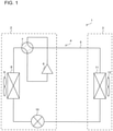
- Fig. 1 is a circuit diagram illustrating an air-conditioning apparatus 1 according to Embodiment 1 of the present disclosure.
- the air-conditioning apparatus 1 is an apparatus that adjusts indoor air, and, as illustrated in Fig. 1 , includes an outdoor unit 2 and an indoor unit 3.
- the outdoor unit 2 includes, for example, a compressor 6, a flow switching device 7, an outdoor heat exchanger 8, an outdoor air-sending device 9, and an expansion portion 10.
- the indoor unit 3 includes, for example, a heat exchanger 11 and air-sending devices 12.
- a heat-medium circuit 4 is formed by connecting the compressor 6, the flow switching device 7, the outdoor heat exchanger 8, the expansion portion 10, and the heat exchanger 11 to each other by a heat-medium pipe 5.
- the compressor 6 sucks in a low-temperature low-pressure heat medium, compresses the sucked-in heat medium, and discharges the heat medium as a high-temperature and high-pressure heat medium.
- the flow switching device 7 switches directions in which the heat medium flows in the heat-medium circuit 4, and is, for example, a four-way valve.
- the outdoor heat exchanger 8 is, for example, a heat exchanger that causes heat to be exchanged between outdoor air and the heat medium.
- the outdoor heat exchanger 8 operates as a condenser at the time of a cooling operation, and operates as an evaporator at the time of a heating operation.
- the outdoor air-sending device 9 is a device that sends outdoor air to the outdoor heat exchanger 8.
- the expansion portion 10 is a pressure reducing valve or an expansion valve that expands a heat medium by reducing the pressure of the heat medium.
- the expansion portion 10 is, for example, an electronic expansion valve that adjusts an opening degree.
- the heat exchanger 11 is, for example, a heat exchanger that causes heat to be exchanged between indoor air and the heat medium.
- the heat exchanger 11 operates as an evaporator at the time of a cooling operation, and operates as a condenser at the time of a heating operation.
- Each air-sending device 12 is a device that sends indoor air to the heat exchanger 11.
- the heat medium may be water, an antifreeze, or refrigerant.
- a cooling operation is described.
- a heat medium sucked into the compressor 6 is compressed and discharged in a high-temperature and high-pressure gaseous state by the compressor 6.
- the high-temperature and high-pressure gaseous heat medium discharged from the compressor 6 passes the flow switching device 7, and flows into the outdoor heat exchanger 8 operating as a condenser.
- the heat medium exchanges heat with outdoor air that is sent by the outdoor air-sending device 9, is condensed, and is liquefied.
- the condensed heat medium in the liquid state flows into the expansion portion 10.
- the heat medium is expanded, is decompressed, and becomes a low-temperature and low-pressure heat medium in a two-phase gas-liquid state.
- the two-phase gas-liquid heat medium flows into the heat exchanger 11 that operates as an evaporator.
- the heat medium exchanges heat with indoor air that is sent by each air-sending device 12, is evaporated, and becomes a gas.
- the indoor air is cooled, and the inside of a room is cooled.
- the low-temperature low-pressure gaseous heat medium that has evaporated passes the flow switching device 7, and is sucked into the compressor 6.
- a heating operation is described.
- a heat medium sucked into the compressor 6 is compressed and discharged in a high-temperature high-pressure gaseous state by the compressor 6.
- the high-temperature high-pressure gaseous heat medium discharged from the compressor 6 passes the flow switching device 7, and flows into the heat exchanger 11 operating as a condenser.
- the heat medium exchanges heat with indoor air that is sent by each air-sending device 12, is condensed, and is liquefied.
- the indoor air is heated, and the inside of a room is heated.
- the condensed heat medium in the liquid state flows into the expansion portion 10.
- the heat medium is expanded, is decompressed, and becomes a low-temperature and low-pressure heat medium in a two-phase gas-liquid state.
- the two-phase gas-liquid heat medium flows into the outdoor heat exchanger 8 that operates as an evaporator.
- the heat medium exchanges heat with outdoor air that is sent by the outdoor air-sending device 9, is evaporated, and becomes a gas.
- the low-temperature low-pressure gaseous heat medium that has evaporated passes the flow switching device 7, and is sucked into the compressor 6.
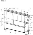
- Fig. 2 is a front perspective view illustrating the indoor unit 3 according to Embodiment 1 of the present disclosure.
- Fig. 3 is a rear perspective view illustrating the indoor unit 3 according to Embodiment 1 of the present disclosure.
- the indoor unit 3 is, for example, a floor-type indoor unit 3 that is placed on a floor inside a room.
- the indoor unit 3 may be a wall-type indoor 3 that is mounted on a wall.
- the indoor unit 3 includes a pair of leg portions 15, a housing 20 that forms an outer portion, and a heat-insulating material 28.
- the pair of leg portions 15 are removably mounted, one on each end of a lower portion of the housing 20 in a width direction, are placed on the floor, and support the housing 20. Therefore, a gap 15a is formed between the housing 20 and the floor. Note that three or more of the leg portions 15 may be provided.
- the housing 20 has a cuboid shape extending in the width direction, and includes a front panel 21, a rear panel 22, two side panels 23, and a top panel 24.
- the front panel 21 is formed by a plurality of panels that are disposed side by side at a front side of the housing 20, and includes a lower-portion panel 25, a one-side-portion panel 26, and an upper-portion panel 27.
- the lower-portion panel 25 is a panel that covers each air-sending device 12 that is accommodated inside the housing 20 (see Fig. 4 ).
- the one-side-portion panel 26 is a panel that is disposed above the lower-portion panel 25, and that covers an electrical-component box that accommodates electrical components (see Fig. 4 ).
- the one-side-portion panel 26 has, for example, three one-side-portion mounting holes 26a. Note that the number of one-side-portion mounting holes 26a is changed as appropriate.
- the upper-portion panel 27 has an L-shape in front view.
- a lower portion of the upper-portion panel 27 is disposed above the lower-portion panel 25 and on a side of the one-side-portion panel 26, and covers a drain pan 40 that is provided below the heat exchanger 11 (see Fig. 4 ).
- the lower portion of the upper-portion panel 27 has, for example, two other-side-portion mounting holes 27a. Note that the number of other-side-portion mounting holes 27 is changed as appropriate.
- An upper portion of the upper-portion panel 27 is disposed above the one-side-portion panel 26, and covers the heat exchanger 11 that is disposed inside the housing 20 (see Fig. 4 ).
- the lower-portion panel 25 and the one-side-portion panel 26 are fixed to the side panels 23 corresponding thereto by, for example, screws.
- the upper-portion panel 27 is fixed to the side panels 23 and the top panel 24 by, for example, screws.
- the rear panel 22 is formed by a plurality of panels that are disposed side by side at a rear side of the housing 20. For example, five rear mounting holes 22a are formed near the center of the rear panel 22. Note that the number of rear mounting holes 22a is changed as appropriate.
- the two side panels 23 are panels that cover respective end portions in the width direction, and function as supports at which devices that are provided inside the housing 20 are installed.
- the leg portions 15 are fixed to lower end portions of the respective side panels 23 by, for example, screws.
- Each side panel 23 includes, for example, two side mounting fittings 23a that are provided toward the rear panel 22.
- the side mounting fittings 23a are used when the indoor unit 3 is fixed to, for example, an indoor wall. Note that the side mounting fittings 23a may be removed when, as in Embodiment 1, the indoor unit 3 is used as a floor type.
- One of the side panels 23 has a drain hole 23b from which moisture produced inside the housing 20 is discharged to the outside of the housing 20.
- a pipe inlet 23c of the heat-medium pipe 5 in which a heat medium that flows into the heat exchanger 11 from the outdoor unit 2 flows and a pipe outlet 23d of the heat-medium pipe 5 in which a heat medium that flows out of the outdoor unit 2 flows are formed in the one of the side panels 23.
- a pipe cover 23f is mounted on a portion of the side panel 23 at which the pipe inlet 23c and the pipe outlet 23d are formed.
- one side mounting hole 23e is formed near the center front side of each of the two side panels 23. Note that the number of side mounting holes 23e is changed as appropriate.
- the top panel 24 is a frame-like member that forms an upper portion of the housing 20, and has an air outlet 20a from which air is blown out.
- the top panel 24 includes a top-surface extending portion 24a that extends upward from an edge portion defining the air outlet 20a. Note that the lower portion of the housing 20 has an air inlet 20b into which air is sucked.
- the heat-insulating material 28 insulates the inside of the housing 20 from heat, and has a rectangular shape.
- the heat-insulating material 28 is fixed to the upper portion of the upper-portion panel 27 by screws.
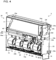
- Fig. 4 is a perspective view illustrating the indoor unit 3 according to Embodiment 1 of the present disclosure after removal of the front panel 21.
- Fig. 5 is a front view illustrating the indoor unit 3 according to Embodiment 1 of the present disclosure after the removal of the front panel 21.
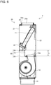
- Fig. 6 is a side sectional view illustrating the indoor unit 3 according to Embodiment 1 of the present disclosure, and is a sectional view along A-A in Fig. 5 .
- Fig. 7 is a side sectional view illustrating the indoor unit 3 according to Embodiment 1 of the present disclosure, and is a sectional view along B-B in Fig. 5 .
- the indoor unit 3 includes a fan guard 30, the air-sending devices 12, the heat exchanger 11, the drain pan 40, a fan plate 50, and a control box 90.
- the fan guard 30 is provided at a bottom side of the housing 20 from the one of the side panels 23 to the other side panel 23.
- the fan guard 30 covers the air inlet 20b, ad prevents a person from touching the air-sending devices 12 through the air inlet 20b with the fingers.
- Fig. 8 is a perspective view illustrating the air-sending devices 12 and the fan plate 50 according to Embodiment 1 of the present disclosure.
- the air-sending devices 12 are provided at an inside lower portion of the housing 20, and are, for example, sirocco fans.
- four air-sending devices 12 are disposed side by side in the width direction of the housing 20, and each have an air-sending opening 12a from which air is blown out at an upper portion of the air-sending device 12.
- the four air-sending devices 12 are connected to each other by the fan plate 50, and are supported by the housing 20 through the fan plate 50 as a result of the fan plate 50 being mounted on the side panels 23 and the rear panel 22.
- a motor 12b that rotationally drives the air-sending devices 12 is provided between the air-sending devices 12.
- Each air-sending device 12 causes an airflow to be generated when the motor 12b rotates the blades, and sends air that has been sucked in from the air inlet 20b of the housing 20 from the air-sending opening 12a to an inside upper portion of the housing 20 in which the heat exchanger 11 is provided.
- the number of air-sending devices 12 may be one to three, or may be five or more.
- the heat exchanger 11 is provided at the inside upper portion of the housing 20, and extends in the width direction of the housing 20.
- the heat exchanger 11 is, for example, a plate-fin-tube heat exchanger, and has a structure in which a plurality of fins are disposed side by side in the width direction and in which a plurality of heat transfer pipes extending in the width direction extend through the fins.
- the heat transfer pipes are connected to the pipe inlet 23c and the pipe outlet 23d.
- the heat exchanger 11 causes heat to be exchanged between a heat medium that flows in the heat transfer pipes and air that is sent from each air-sending device 12.
- the heat exchanger 11 is supported by the housing 20 and the drain pan 40.
- the heat exchanger 11 is tilted with respect to an up-down direction of the housing 20. Specifically, the heat exchanger 11 is tilted downward toward the front panel 21 from the rear panel 22. Therefore, air that is sent from each air-sending device 12 easily strikes the entire heat exchanger 11.
- the drain pan 40 supports a lower portion of the heat exchanger 11, and receives water that flows from the heat exchanger 11.
- the drain pan 40 extends in the width direction of the housing 20, and two end portions thereof are fixed to the two side panels 23.
- the drain pan 40 is placed on the fan plate 50.
- the drain pan 40 is tilted downward toward the one of the side panels 23 from the other side panel 23. Therefore, moisture that has dropped from the drain pan 40 flows toward the one of the side panels 23 and is discharged to the outside of the housing 20 through the drain hole 23b of the one of the side panels 23.
- Fig. 9 is a perspective view illustrating the fan plate 50 according to Embodiment 1 of the present disclosure.
- Fig. 10 is a side view illustrating the fan plate 50 according to Embodiment 1 of the present disclosure.
- the fan plate 50 is a plate that separates the inside lower portion and the inside upper portion of the housing 20 from each other.
- the fan plate 50 includes a fan connection portion 60, a guide portion 70, and a placement portion 80.
- the fan plate 50 is manufactured by bending one plate-shaped material.
- the fan connection portion 60 is a plate-shaped member that surrounds the air-sending openings 12a of the air-sending devices 12.
- the fan connection portion 60 extends in the width direction of the housing 20, and has four connection openings 61 in which portions of the four air-sending devices 12 that are nearer the respective air-sending openings 12a are inserted.
- the air-sending devices 12 are supported by the fan plate 50. Note that the number of connection openings 61 is changed as appropriate depending upon the number of air-sending devices 12.
- the fan connection portion 60 includes two first connection flange portions 62 that protrude toward the air-sending devices 12 from respective end portions of the fan connection portion 60 in the width direction of the housing 20.
- the two first connection flange portions 62 come into contact with the respective side panels 23 of the housing 20.
- the fan connection portion 60 includes a second connection flange portion 63 that protrudes from, of end portions of the fan connection portion 60 in a depth direction of the housing 20, a rear-end portion opposite to the guide portion 70 with the second connection flange portion 63 being tilted toward the air-sending devices 12 and the rear.
- the second connection flange portion 63 has, for example, five second connection mounting holes 63a. For example, screws are inserted and screwed into the five second connection mounting holes 63a and the five rear mounting holes 22a formed in the rear panel 22 to support the fan connection portion 60 by the rear panel 22.
- second connection mounting holes 63a is changed as appropriate depending upon the number of rear mounting holes 22a.
- the protrusion length of the second connection flange portion 63 is the same as the protrusion length of each first connection flange portion 62.
- the second connection flange and the first connection flange portions 62 are not continuously provided, and that there is a gap 64 between the second connection flange and each first connection flange portion 62.
- the guide portion 70 is a plate-shaped member that extends upward from, of the end portions of the fan connection portion 60 in the depth direction of the housing 20, a front end portion opposite to the second connection flange portion 63.
- the guide portion 70 extends in the width direction of the housing 20, and the length of the guide portion 70 is the same as the length of the fan connection portion 60. Since the guide portion 70 extends upward by a distance L from the fan connection portion 60, the air-sending openings 12a of the air-sending devices 12 and the heat exchanger 11 are disposed further apart from each other (see Fig. 6 ). Therefore, the flow of air that is blown out from the air-sending openings 12a of the air-sending devices 12 is rectified before the air reaches the heat exchanger 11. In this way, since the air whose flow has been rectified strikes the heat exchanger 11, the indoor unit 3 can improve the heat-exchange efficiency of the heat exchanger 11.
- the guide portion 70 has, for example, four guide mounting holes 70a.
- the four guide mounting holes 70a are used when the control box 90 is mounted on the guide portion 70.
- the guide portion 70 includes two guide flange portions 71 that protrude toward the front from two end portions of the guide portion 70 in the width direction of the housing 20.
- the two guide flange portions 71 come into contact with a corresponding one of the two side panels 23 of the housing 20 when the fan plate 50 is mounted on the housing 20.
- the protrusion length of each guide flange portion 71 is the same as the protrusion length of each first connection flange portion 62 and the protrusion length of the second connection flange portion 63.
- the placement portion 80 is a plate-shaped member that is formed continuously with, of the end portions of the guide portion 70 in the depth direction of the housing 20, a front end portion opposite to the fan connection portion 60, and that extends toward the front. In the width direction of the housing 20, the length of the placement portion 80 is the same as the length of the fan connection portion 60 and the length of the guide portion 70. As illustrated in Fig. 6 , the drain pan 40 is placed on the placement portion 80, and the placement portion 80 supports the drain pan 40. By placing the drain pan 40 on the placement portion 80 of the fan plate 50, the stability of the drain pan 40 is increased. As illustrated in Fig. 8 , the placement portion 80 has a cutout portion 81 into which the control box 90 is inserted.
- the cutout portion 81 extends in the width direction of the housing 20 at a location of the placement portion 80 that is nearer the one of the side panels 23.
- An end portion of the placement portion 80 that is nearer the one of the side panels 23 has a wire cutout portion 82 that is smaller than the cutout portion 81.
- a wire 92 connected to the control box 90 is inserted in the wire cutout portion 82 (see Figs. 4 and 5 ).
- the placement portion 80 includes two first placement flange portions 83 that protrude toward the air-sending devices 12 from two end portions of the placement portion 80 in the width direction of the housing 20.
- the two first placement flange portions 83 come into contact with a corresponding one of the two side panels 23 of the housing 20 when the fan plate 50 is mounted on the housing 20.
- the two first placement flange portions 83 each have, for example, one first placement mounting hole 83a. For example, screws are inserted and screwed into the one first placement mounting hole 83a of each first placement flange portion 83 and the one side mounting hole 23e formed in each side panel 23 to support the placement portion 80 by the side panels 23.
- each first placement flange portion 83 is the same as the protrusion length of each first connection flange portion 62, the protrusion length of the second connection flange portion 63, and the protrusion length of each guide flange portion 71.
- the placement portion 80 has a second placement flange portion 84 that protrudes toward the air-sending devices 12 from, of end portions of the placement portion 80 in the depth direction of the housing 20, a front end portion opposite to the guide portion 70.
- the second placement flange portion 84 comes into contact with the front panel 21 of the housing 20 when the fan plate 50 is mounted on the housing 20.
- the second placement flange portion 84 has, for example, two second placement mounting holes 84a (see Figs. 4 and 5 ). For example, screws are inserted and screwed into the two second placement mounting holes 84a and the two other-side-portion mounting holes 27a formed in the upper-portion panel 27 of the front panel 21 to support the placement portion 80 by the upper-portion panel 27 of the front panel 21.
- the number of second placement mounting holes 84a is changed as appropriate depending upon the number of other-side-portion mounting holes 27a. In this way, since the fan plate 50 is supported at a plurality of portions of the housing 20, the stability of the fan plate 50 is increased. As illustrated in Fig. 10 , the protrusion length of the second placement flange portion 84 is longer than the protrusion length of each first placement flange portion 83.
- Fig. 11 is a perspective view illustrating the control box 90 according to Embodiment 1 of the present disclosure.
- the control box 90 is a box body that is connected to the air-sending devices 12 and includes therein a control board 91 that controls the operation of the air-sending devices 12 (see Figs. 4 and 5 ).
- a plurality of electronic components are installed on the control board 91, and the wire 92 is connected to the control board 91.
- a portion of the wire 92 is connected to the heat exchanger 11 through the wire cutout portion 82 of the placement portion 80 of the fan plate 50.
- a portion of the wire 92 is also connected to the motor 12b.
- the control box 90 is a box body extending in the width direction of the housing 20, and the length of the control box 90 in the depth direction of the housing 20 from an upper portion to a lower portion is long.
- the upper portion of the control box 90 is inserted into the cutout portion 81 of the placement portion 80 of the fan plate 50 and protrudes from the fan plate 50. Therefore, even if the height of an accommodation space 29 illustrated in Fig. 7 is lower than the height of the control box 90, the control box 90 can be accommodated in the accommodation space 29.
- the upper portion of the control box 90 has three first control mounting holes 90a.
- first control mounting holes 90a screws are inserted and screwed into the three first control mounting holes 90a and the three one-side-portion mounting holes 26a (see Fig. 2 ) formed in the one-side-portion panel 26 of the front panel 21 to support the control box 90 by the one-side-portion panel 26 of the front panel 21.
- the number of first control mounting holes 90a is changed as appropriate depending upon the number of one-side-portion mounting holes 26a.
- Control mounting fittings 93 extending toward the rear of the housing 20 are provided on a corresponding one of two side surfaces of the control box 90.
- Each of the two control mounting fittings 93 has two second control mounting holes 93a.
- screws are inserted and screwed into the total of four second control mounting holes 93a and the four guide mounting holes 70a (see Fig. 9 ) formed in the guide portion 70 of the fan plate 50 to mount the control box 90 on the guide portion 70 of the fan plate 50.
- the number of second control mounting holes 93a is changed as appropriate depending upon the number of guide mounting holes 70a.
- the accommodation space 29 in the housing 20 is described with reference to Fig. 7 .
- the accommodation space 29 is formed between the guide portion 70 of the fan plate 50 and the front panel 21 of the housing 20.
- the control box 90 is provided in the accommodation space 29.
- the control box 90 is covered by the one-side-portion panel 26 of the front panel 21 (see Fig. 2 ).
- the accommodation space 29, serving as an excess space is formed between the guide portion 70 and the front panel 21 of the housing 20.
- the size of the housing 20 can be maximally increased.
- the accommodation space 29 not only is formed between the guide portion 70 and the front panel 21 of the housing 20, but also may be formed between the guide portion 70 and any one of the surfaces of the housing 20.
- the control box 90 is tilted with respect to the guide portion 70. Therefore, even if the height of the accommodation space 29 is lower than the height of the control box 90, since the length of the control box 90 in the depth direction is used for the height of the control box 90, the control box 90 can be accommodated in the accommodation space 29 in terms of their heights while the volume of the control box 90 is ensured. Note that the control box 90 is tilted with respect to the guide portion 70 so that the control board 91 of the control box 90 faces downward toward the front. Therefore, dust is prevented from falling and remaining on the control board 91.
- the fan plate 50 includes the guide portion 70 that guides air that is sent from the air-sending devices 12 toward the heat exchanger 11, and the guide portion 70 extends upward by the distance L from the fan connection portion 60. Therefore, the air-sending hole 12a of each air-sending device 12 and the heat exchanger 11 are far apart from each other, and the flow of the air that is sent from each air-sending device 12 is rectified before the air reaches the heat exchanger 11. In this way, since the air whose flow has been rectified strikes the heat exchanger 11, the indoor unit 3 can improve the heat-exchange efficiency of the heat exchanger 11.
- the fan plate 50 is manufactured by bending one plate-shaped material. In this way, by only bending the plate-shaped material, the accommodation space 29 that accommodates the control box 90 can be formed. Therefore, manufacturing costs can be reduced.
Landscapes
- Engineering & Computer Science (AREA)
- Chemical & Material Sciences (AREA)
- Combustion & Propulsion (AREA)
- Mechanical Engineering (AREA)
- General Engineering & Computer Science (AREA)
- Coating Apparatus (AREA)
- Air Filters, Heat-Exchange Apparatuses, And Housings Of Air-Conditioning Units (AREA)
Abstract
Description
- The present disclosure relates to an indoor unit including a fan plate that separates an inside lower portion and an inside upper portion of a housing from each other.
- Hitherto, as an indoor unit of an air-conditioning apparatus, an indoor unit including a fan plate that separates an inside lower portion and an inside upper portion of a housing from each other has been known.
Patent Literature 1 discloses a floor-type air-conditioning indoor unit in which a fan and a heat-exchange coil are provided inside a casing. InPatent Literature 1, the fan is provided at an inside lower portion of the casing, and the heat-exchange coil is provided at an inside upper portion of the casing. The inside lower portion and the inside upper portion of the casing are separated from each other by a partition plate corresponding to the fan plate. - Patent Literature 1:
Japanese Unexamined Patent Application Publication No. 11-281081 - However, in the air-conditioning indoor unit disclosed in
Patent Literature 1, the distance between an air-sending opening of the fan and a heat exchanger is small inside the casing. Therefore, after air that is sent by the fan has been blown out from the air-sending opening of the fan, the air immediately strikes the heat exchanger. That is, the air that has been blown out from the air-sending opening of the fan strikes the heat exchanger without the flow of the air being rectified. Therefore, the heat-exchange efficiency of the heat exchanger is reduced. - The present disclosure has been made to such solve problems described above, and an object thereof is to provide an indoor unit that improves the heat-exchange efficiency of a heat exchanger.
- An indoor unit according to an embodiment of the present disclosure includes a housing forming an outer portion, and having an air inlet into which air is sucked and an air outlet from which air is blown out, the air inlet being formed in a lower portion of the housing, the air outlet being formed in an upper portion of the housing; an air-sending device provided at an inside lower portion of the housing, and sending the air sucked in from the air inlet from an air-sending opening to an inside upper portion of the housing, the air-sending opening being formed in an upper portion of the air-sending device; a heat exchanger provided at the inside upper portion of the housing, and causing heat to be exchanged between air sent from the air-sending device and a heat medium; and a fan plate separating the inside lower portion and the inside upper portion of the housing from each other. The fan plate includes a fan connection portion surrounding the air-sending opening of the air-sending device, and a guide portion extending upward from the fan connection portion and guiding the air sent from the air-sending device toward the heat exchanger.
- According to an embodiment of the present disclosure, the fan plate includes a guide portion that guides air that is sent from the air-sending device toward the heat exchanger, and the guide portion extends upward from the fan connection portion. Therefore, the air-sending opening of the air-sending device and the heat exchanger are far apart from each other, and the flow of the air that is sent from the air-sending device is rectified before the air reaches the heat exchanger. In this way, since the air whose flow has been rectified strikes the heat exchanger, the indoor unit can improve the heat-exchange efficiency of the heat exchanger.
-
- [
Fig. 1] Fig. 1 is a circuit diagram illustrating an air-conditioning apparatus according toEmbodiment 1 of the present disclosure. - [
Fig. 2] Fig. 2 is a front perspective view illustrating an indoor unit according toEmbodiment 1 of the present disclosure. - [
Fig. 3] Fig. 3 is a rear perspective view illustrating the indoor unit according toEmbodiment 1 of the present disclosure. - [
Fig. 4] Fig. 4 is a perspective view illustrating the indoor unit according toEmbodiment 1 of the present disclosure after removal of a front panel. - [
Fig. 5] Fig. 5 is a front view of the indoor unit according toEmbodiment 1 of the present disclosure after the removal of the front panel. - [
Fig. 6] Fig. 6 is a side sectional view illustrating the indoor unit according toEmbodiment 1 of the present disclosure. - [
Fig. 7] Fig. 7 is a side sectional view of the indoor unit according toEmbodiment 1 of the present disclosure. - [
Fig. 8] Fig. 8 is a perspective view illustrating air-sending devices and a fan plate according toEmbodiment 1 of the present disclosure. - [
Fig. 9] Fig. 9 is a perspective view illustrating the fan plate according toEmbodiment 1 of the present disclosure. - [
Fig. 10] Fig. 10 is a side view illustrating the fan plate according toEmbodiment 1 of the present disclosure. - [
Fig. 11] Fig. 11 is a perspective view illustrating a control box according toEmbodiment 1 of the present disclosure. - Embodiment of an indoor unit according to the present disclosure is described below with reference to the drawings. Note that the present disclosure is not limited to Embodiment that is described below. In the figures below including
Fig. 1 , the relationship between the sizes of the structural members may differ from the relationship between the sizes of the actual structural members. Although in the description below, to facilitate understanding, terms indicating directions are used as appropriate, these terms are used for description and do not limit the present disclosure. The terms indicating directions are, for example, "up", "down", "right", "left", "front", and "rear". -
Fig. 1 is a circuit diagram illustrating an air-conditioning apparatus 1 according toEmbodiment 1 of the present disclosure. The air-conditioning apparatus 1 is an apparatus that adjusts indoor air, and, as illustrated inFig. 1 , includes anoutdoor unit 2 and anindoor unit 3. Theoutdoor unit 2 includes, for example, acompressor 6, aflow switching device 7, anoutdoor heat exchanger 8, an outdoor air-sending device 9, and anexpansion portion 10. Theindoor unit 3 includes, for example, aheat exchanger 11 and air-sending devices 12. - A heat-
medium circuit 4 is formed by connecting thecompressor 6, theflow switching device 7, theoutdoor heat exchanger 8, theexpansion portion 10, and theheat exchanger 11 to each other by a heat-medium pipe 5. Thecompressor 6 sucks in a low-temperature low-pressure heat medium, compresses the sucked-in heat medium, and discharges the heat medium as a high-temperature and high-pressure heat medium. Theflow switching device 7 switches directions in which the heat medium flows in the heat-medium circuit 4, and is, for example, a four-way valve. Theoutdoor heat exchanger 8 is, for example, a heat exchanger that causes heat to be exchanged between outdoor air and the heat medium. Theoutdoor heat exchanger 8 operates as a condenser at the time of a cooling operation, and operates as an evaporator at the time of a heating operation. The outdoor air-sending device 9 is a device that sends outdoor air to theoutdoor heat exchanger 8. - The
expansion portion 10 is a pressure reducing valve or an expansion valve that expands a heat medium by reducing the pressure of the heat medium. Theexpansion portion 10 is, for example, an electronic expansion valve that adjusts an opening degree. Theheat exchanger 11 is, for example, a heat exchanger that causes heat to be exchanged between indoor air and the heat medium. Theheat exchanger 11 operates as an evaporator at the time of a cooling operation, and operates as a condenser at the time of a heating operation. Each air-sending device 12 is a device that sends indoor air to theheat exchanger 11. Note that the heat medium may be water, an antifreeze, or refrigerant. - Next, operation modes of the air-
conditioning apparatus 1 are described. First, a cooling operation is described. In the cooling operation, a heat medium sucked into thecompressor 6 is compressed and discharged in a high-temperature and high-pressure gaseous state by thecompressor 6. The high-temperature and high-pressure gaseous heat medium discharged from thecompressor 6 passes theflow switching device 7, and flows into theoutdoor heat exchanger 8 operating as a condenser. - Then, at the
outdoor heat exchanger 8, the heat medium exchanges heat with outdoor air that is sent by the outdoor air-sending device 9, is condensed, and is liquefied. The condensed heat medium in the liquid state flows into theexpansion portion 10. Then, at theexpansion portion 10, the heat medium is expanded, is decompressed, and becomes a low-temperature and low-pressure heat medium in a two-phase gas-liquid state. Then, the two-phase gas-liquid heat medium flows into theheat exchanger 11 that operates as an evaporator. Then, at theheat exchanger 11, the heat medium exchanges heat with indoor air that is sent by each air-sendingdevice 12, is evaporated, and becomes a gas. At this time, the indoor air is cooled, and the inside of a room is cooled. The low-temperature low-pressure gaseous heat medium that has evaporated passes theflow switching device 7, and is sucked into thecompressor 6. - Next, a heating operation is described. In the heating operation, a heat medium sucked into the
compressor 6 is compressed and discharged in a high-temperature high-pressure gaseous state by thecompressor 6. The high-temperature high-pressure gaseous heat medium discharged from thecompressor 6 passes theflow switching device 7, and flows into theheat exchanger 11 operating as a condenser. Then, at theheat exchanger 11, the heat medium exchanges heat with indoor air that is sent by each air-sendingdevice 12, is condensed, and is liquefied. At this time, the indoor air is heated, and the inside of a room is heated. The condensed heat medium in the liquid state flows into theexpansion portion 10. Then, at theexpansion portion 10, the heat medium is expanded, is decompressed, and becomes a low-temperature and low-pressure heat medium in a two-phase gas-liquid state. Then, the two-phase gas-liquid heat medium flows into theoutdoor heat exchanger 8 that operates as an evaporator. Then, at theoutdoor heat exchanger 8, the heat medium exchanges heat with outdoor air that is sent by the outdoor air-sending device 9, is evaporated, and becomes a gas. The low-temperature low-pressure gaseous heat medium that has evaporated passes theflow switching device 7, and is sucked into thecompressor 6. -
Fig. 2 is a front perspective view illustrating theindoor unit 3 according toEmbodiment 1 of the present disclosure.Fig. 3 is a rear perspective view illustrating theindoor unit 3 according toEmbodiment 1 of the present disclosure. Next, theindoor unit 3 is described in detail. Theindoor unit 3 is, for example, a floor-typeindoor unit 3 that is placed on a floor inside a room. Note that theindoor unit 3 may be a wall-type indoor 3 that is mounted on a wall. - As illustrated in
Figs. 2 and3 , theindoor unit 3 includes a pair ofleg portions 15, ahousing 20 that forms an outer portion, and a heat-insulatingmaterial 28. The pair ofleg portions 15 are removably mounted, one on each end of a lower portion of thehousing 20 in a width direction, are placed on the floor, and support thehousing 20. Therefore, agap 15a is formed between thehousing 20 and the floor. Note that three or more of theleg portions 15 may be provided. - The
housing 20 has a cuboid shape extending in the width direction, and includes afront panel 21, arear panel 22, twoside panels 23, and atop panel 24. Thefront panel 21 is formed by a plurality of panels that are disposed side by side at a front side of thehousing 20, and includes a lower-portion panel 25, a one-side-portion panel 26, and an upper-portion panel 27. The lower-portion panel 25 is a panel that covers each air-sendingdevice 12 that is accommodated inside the housing 20 (seeFig. 4 ). The one-side-portion panel 26 is a panel that is disposed above the lower-portion panel 25, and that covers an electrical-component box that accommodates electrical components (seeFig. 4 ). The one-side-portion panel 26 has, for example, three one-side-portion mounting holes 26a. Note that the number of one-side-portion mounting holes 26a is changed as appropriate. - The upper-
portion panel 27 has an L-shape in front view. A lower portion of the upper-portion panel 27 is disposed above the lower-portion panel 25 and on a side of the one-side-portion panel 26, and covers adrain pan 40 that is provided below the heat exchanger 11 (seeFig. 4 ). The lower portion of the upper-portion panel 27 has, for example, two other-side-portion mounting holes 27a. Note that the number of other-side-portion mounting holes 27 is changed as appropriate. An upper portion of the upper-portion panel 27 is disposed above the one-side-portion panel 26, and covers theheat exchanger 11 that is disposed inside the housing 20 (seeFig. 4 ). The lower-portion panel 25 and the one-side-portion panel 26 are fixed to theside panels 23 corresponding thereto by, for example, screws. The upper-portion panel 27 is fixed to theside panels 23 and thetop panel 24 by, for example, screws. Therear panel 22 is formed by a plurality of panels that are disposed side by side at a rear side of thehousing 20. For example, fiverear mounting holes 22a are formed near the center of therear panel 22. Note that the number of rear mountingholes 22a is changed as appropriate. - The two
side panels 23 are panels that cover respective end portions in the width direction, and function as supports at which devices that are provided inside thehousing 20 are installed. Theleg portions 15 are fixed to lower end portions of therespective side panels 23 by, for example, screws. Eachside panel 23 includes, for example, twoside mounting fittings 23a that are provided toward therear panel 22. Theside mounting fittings 23a are used when theindoor unit 3 is fixed to, for example, an indoor wall. Note that theside mounting fittings 23a may be removed when, as inEmbodiment 1, theindoor unit 3 is used as a floor type. - One of the
side panels 23 has adrain hole 23b from which moisture produced inside thehousing 20 is discharged to the outside of thehousing 20. In addition, apipe inlet 23c of the heat-medium pipe 5 in which a heat medium that flows into theheat exchanger 11 from theoutdoor unit 2 flows and apipe outlet 23d of the heat-medium pipe 5 in which a heat medium that flows out of theoutdoor unit 2 flows are formed in the one of theside panels 23. Note that apipe cover 23f is mounted on a portion of theside panel 23 at which thepipe inlet 23c and thepipe outlet 23d are formed. Further, for example, oneside mounting hole 23e is formed near the center front side of each of the twoside panels 23. Note that the number ofside mounting holes 23e is changed as appropriate. Thetop panel 24 is a frame-like member that forms an upper portion of thehousing 20, and has anair outlet 20a from which air is blown out. Thetop panel 24 includes a top-surface extending portion 24a that extends upward from an edge portion defining theair outlet 20a. Note that the lower portion of thehousing 20 has anair inlet 20b into which air is sucked. - The heat-insulating
material 28 insulates the inside of thehousing 20 from heat, and has a rectangular shape. The heat-insulatingmaterial 28 is fixed to the upper portion of the upper-portion panel 27 by screws. -
Fig. 4 is a perspective view illustrating theindoor unit 3 according toEmbodiment 1 of the present disclosure after removal of thefront panel 21.Fig. 5 is a front view illustrating theindoor unit 3 according toEmbodiment 1 of the present disclosure after the removal of thefront panel 21.Fig. 6 is a side sectional view illustrating theindoor unit 3 according toEmbodiment 1 of the present disclosure, and is a sectional view along A-A inFig. 5 .Fig. 7 is a side sectional view illustrating theindoor unit 3 according toEmbodiment 1 of the present disclosure, and is a sectional view along B-B inFig. 5 . Next, the devices that are provided inside thehousing 20 are described. As illustrated inFigs. 4 to 7 , theindoor unit 3 includes afan guard 30, the air-sendingdevices 12, theheat exchanger 11, thedrain pan 40, afan plate 50, and acontrol box 90. - As illustrated in
Fig. 4 , thefan guard 30 is provided at a bottom side of thehousing 20 from the one of theside panels 23 to theother side panel 23. Thefan guard 30 covers theair inlet 20b, ad prevents a person from touching the air-sendingdevices 12 through theair inlet 20b with the fingers. -
Fig. 8 is a perspective view illustrating the air-sendingdevices 12 and thefan plate 50 according toEmbodiment 1 of the present disclosure. As illustrated inFigs. 4 to 7 , the air-sendingdevices 12 are provided at an inside lower portion of thehousing 20, and are, for example, sirocco fans. As illustrated inFig. 8 , for example, four air-sendingdevices 12 are disposed side by side in the width direction of thehousing 20, and each have an air-sendingopening 12a from which air is blown out at an upper portion of the air-sendingdevice 12. The four air-sendingdevices 12 are connected to each other by thefan plate 50, and are supported by thehousing 20 through thefan plate 50 as a result of thefan plate 50 being mounted on theside panels 23 and therear panel 22. - Note that a
motor 12b that rotationally drives the air-sendingdevices 12 is provided between the air-sendingdevices 12. Each air-sendingdevice 12 causes an airflow to be generated when themotor 12b rotates the blades, and sends air that has been sucked in from theair inlet 20b of thehousing 20 from the air-sendingopening 12a to an inside upper portion of thehousing 20 in which theheat exchanger 11 is provided. Note that, although, inEmbodiment 1, an example in which there are four air-sendingdevices 12 is given, the number of air-sendingdevices 12 may be one to three, or may be five or more. - As illustrated in
Figs. 4 to 7 , theheat exchanger 11 is provided at the inside upper portion of thehousing 20, and extends in the width direction of thehousing 20. Theheat exchanger 11 is, for example, a plate-fin-tube heat exchanger, and has a structure in which a plurality of fins are disposed side by side in the width direction and in which a plurality of heat transfer pipes extending in the width direction extend through the fins. At a portion of theheat exchanger 11 that is nearer the one of theside panels 23, the heat transfer pipes are connected to thepipe inlet 23c and thepipe outlet 23d. Theheat exchanger 11 causes heat to be exchanged between a heat medium that flows in the heat transfer pipes and air that is sent from each air-sendingdevice 12. As illustrated inFigs. 6 and7 , theheat exchanger 11 is supported by thehousing 20 and thedrain pan 40. Theheat exchanger 11 is tilted with respect to an up-down direction of thehousing 20. Specifically, theheat exchanger 11 is tilted downward toward thefront panel 21 from therear panel 22. Therefore, air that is sent from each air-sendingdevice 12 easily strikes theentire heat exchanger 11. - As illustrated in
Figs. 4 to 7 , thedrain pan 40 supports a lower portion of theheat exchanger 11, and receives water that flows from theheat exchanger 11. Thedrain pan 40 extends in the width direction of thehousing 20, and two end portions thereof are fixed to the twoside panels 23. Thedrain pan 40 is placed on thefan plate 50. Thedrain pan 40 is tilted downward toward the one of theside panels 23 from theother side panel 23. Therefore, moisture that has dropped from thedrain pan 40 flows toward the one of theside panels 23 and is discharged to the outside of thehousing 20 through thedrain hole 23b of the one of theside panels 23. -
Fig. 9 is a perspective view illustrating thefan plate 50 according toEmbodiment 1 of the present disclosure.Fig. 10 is a side view illustrating thefan plate 50 according toEmbodiment 1 of the present disclosure. As illustrated inFigs. 6 and7 , thefan plate 50 is a plate that separates the inside lower portion and the inside upper portion of thehousing 20 from each other. As illustrated inFigs. 8 to 10 , thefan plate 50 includes afan connection portion 60, aguide portion 70, and aplacement portion 80. Thefan plate 50 is manufactured by bending one plate-shaped material. - The
fan connection portion 60 is a plate-shaped member that surrounds the air-sendingopenings 12a of the air-sendingdevices 12. Thefan connection portion 60 extends in the width direction of thehousing 20, and has fourconnection openings 61 in which portions of the four air-sendingdevices 12 that are nearer the respective air-sendingopenings 12a are inserted. By inserting the portions of the air-sendingdevices 12 that are nearer the respective air-sendingopenings 12a into thefan connection portion 60 and fixing them to thefan connection portion 60, the air-sendingdevices 12 are supported by thefan plate 50. Note that the number ofconnection openings 61 is changed as appropriate depending upon the number of air-sendingdevices 12. - The
fan connection portion 60 includes two firstconnection flange portions 62 that protrude toward the air-sendingdevices 12 from respective end portions of thefan connection portion 60 in the width direction of thehousing 20. When thefan plate 50 is mounted on thehousing 20, the two firstconnection flange portions 62 come into contact with therespective side panels 23 of thehousing 20. - The
fan connection portion 60 includes a secondconnection flange portion 63 that protrudes from, of end portions of thefan connection portion 60 in a depth direction of thehousing 20, a rear-end portion opposite to theguide portion 70 with the secondconnection flange portion 63 being tilted toward the air-sendingdevices 12 and the rear. When thefan plate 50 is mounted on thehousing 20, the secondconnection flange portion 63 comes into contact with therear panel 22 of thehousing 20. The secondconnection flange portion 63 has, for example, five secondconnection mounting holes 63a. For example, screws are inserted and screwed into the five secondconnection mounting holes 63a and the fiverear mounting holes 22a formed in therear panel 22 to support thefan connection portion 60 by therear panel 22. Note that the number of secondconnection mounting holes 63a is changed as appropriate depending upon the number of rear mountingholes 22a. The protrusion length of the secondconnection flange portion 63 is the same as the protrusion length of each firstconnection flange portion 62. Note that the second connection flange and the firstconnection flange portions 62 are not continuously provided, and that there is agap 64 between the second connection flange and each firstconnection flange portion 62. - The
guide portion 70 is a plate-shaped member that extends upward from, of the end portions of thefan connection portion 60 in the depth direction of thehousing 20, a front end portion opposite to the secondconnection flange portion 63. Theguide portion 70 extends in the width direction of thehousing 20, and the length of theguide portion 70 is the same as the length of thefan connection portion 60. Since theguide portion 70 extends upward by a distance L from thefan connection portion 60, the air-sendingopenings 12a of the air-sendingdevices 12 and theheat exchanger 11 are disposed further apart from each other (seeFig. 6 ). Therefore, the flow of air that is blown out from the air-sendingopenings 12a of the air-sendingdevices 12 is rectified before the air reaches theheat exchanger 11. In this way, since the air whose flow has been rectified strikes theheat exchanger 11, theindoor unit 3 can improve the heat-exchange efficiency of theheat exchanger 11. - The
guide portion 70 has, for example, fourguide mounting holes 70a. The fourguide mounting holes 70a are used when thecontrol box 90 is mounted on theguide portion 70. Note that the number ofguide mounting holes 70a is changed as appropriate. Theguide portion 70 includes twoguide flange portions 71 that protrude toward the front from two end portions of theguide portion 70 in the width direction of thehousing 20. The twoguide flange portions 71 come into contact with a corresponding one of the twoside panels 23 of thehousing 20 when thefan plate 50 is mounted on thehousing 20. Note that the protrusion length of eachguide flange portion 71 is the same as the protrusion length of each firstconnection flange portion 62 and the protrusion length of the secondconnection flange portion 63. - The
placement portion 80 is a plate-shaped member that is formed continuously with, of the end portions of theguide portion 70 in the depth direction of thehousing 20, a front end portion opposite to thefan connection portion 60, and that extends toward the front. In the width direction of thehousing 20, the length of theplacement portion 80 is the same as the length of thefan connection portion 60 and the length of theguide portion 70. As illustrated inFig. 6 , thedrain pan 40 is placed on theplacement portion 80, and theplacement portion 80 supports thedrain pan 40. By placing thedrain pan 40 on theplacement portion 80 of thefan plate 50, the stability of thedrain pan 40 is increased. As illustrated inFig. 8 , theplacement portion 80 has acutout portion 81 into which thecontrol box 90 is inserted. Thecutout portion 81 extends in the width direction of thehousing 20 at a location of theplacement portion 80 that is nearer the one of theside panels 23. An end portion of theplacement portion 80 that is nearer the one of theside panels 23 has awire cutout portion 82 that is smaller than thecutout portion 81. Awire 92 connected to thecontrol box 90 is inserted in the wire cutout portion 82 (seeFigs. 4 and5 ). - The
placement portion 80 includes two firstplacement flange portions 83 that protrude toward the air-sendingdevices 12 from two end portions of theplacement portion 80 in the width direction of thehousing 20. The two firstplacement flange portions 83 come into contact with a corresponding one of the twoside panels 23 of thehousing 20 when thefan plate 50 is mounted on thehousing 20. The two firstplacement flange portions 83 each have, for example, one firstplacement mounting hole 83a. For example, screws are inserted and screwed into the one firstplacement mounting hole 83a of each firstplacement flange portion 83 and the oneside mounting hole 23e formed in eachside panel 23 to support theplacement portion 80 by theside panels 23. Note that the number of firstplacement mounting holes 83a is changed as appropriate depending upon the number ofside mounting holes 23e. The protrusion length of each firstplacement flange portion 83 is the same as the protrusion length of each firstconnection flange portion 62, the protrusion length of the secondconnection flange portion 63, and the protrusion length of eachguide flange portion 71. - The
placement portion 80 has a secondplacement flange portion 84 that protrudes toward the air-sendingdevices 12 from, of end portions of theplacement portion 80 in the depth direction of thehousing 20, a front end portion opposite to theguide portion 70. The secondplacement flange portion 84 comes into contact with thefront panel 21 of thehousing 20 when thefan plate 50 is mounted on thehousing 20. The secondplacement flange portion 84 has, for example, two secondplacement mounting holes 84a (seeFigs. 4 and5 ). For example, screws are inserted and screwed into the two secondplacement mounting holes 84a and the two other-side-portion mounting holes 27a formed in the upper-portion panel 27 of thefront panel 21 to support theplacement portion 80 by the upper-portion panel 27 of thefront panel 21. Note that the number of secondplacement mounting holes 84a is changed as appropriate depending upon the number of other-side-portion mounting holes 27a. In this way, since thefan plate 50 is supported at a plurality of portions of thehousing 20, the stability of thefan plate 50 is increased. As illustrated inFig. 10 , the protrusion length of the secondplacement flange portion 84 is longer than the protrusion length of each firstplacement flange portion 83. -
Fig. 11 is a perspective view illustrating thecontrol box 90 according toEmbodiment 1 of the present disclosure. Thecontrol box 90 is a box body that is connected to the air-sendingdevices 12 and includes therein acontrol board 91 that controls the operation of the air-sending devices 12 (seeFigs. 4 and5 ). A plurality of electronic components are installed on thecontrol board 91, and thewire 92 is connected to thecontrol board 91. As described above, a portion of thewire 92 is connected to theheat exchanger 11 through thewire cutout portion 82 of theplacement portion 80 of thefan plate 50. A portion of thewire 92 is also connected to themotor 12b. - As illustrated in
Fig. 11 , thecontrol box 90 is a box body extending in the width direction of thehousing 20, and the length of thecontrol box 90 in the depth direction of thehousing 20 from an upper portion to a lower portion is long. Here, as illustrated inFig. 8 , the upper portion of thecontrol box 90 is inserted into thecutout portion 81 of theplacement portion 80 of thefan plate 50 and protrudes from thefan plate 50. Therefore, even if the height of an accommodation space 29 illustrated inFig. 7 is lower than the height of thecontrol box 90, thecontrol box 90 can be accommodated in the accommodation space 29. The upper portion of thecontrol box 90 has three firstcontrol mounting holes 90a. For example, screws are inserted and screwed into the three firstcontrol mounting holes 90a and the three one-side-portion mounting holes 26a (seeFig. 2 ) formed in the one-side-portion panel 26 of thefront panel 21 to support thecontrol box 90 by the one-side-portion panel 26 of thefront panel 21. Note that the number of firstcontrol mounting holes 90a is changed as appropriate depending upon the number of one-side-portion mounting holes 26a. -
Control mounting fittings 93 extending toward the rear of thehousing 20 are provided on a corresponding one of two side surfaces of thecontrol box 90. Each of the twocontrol mounting fittings 93 has two secondcontrol mounting holes 93a. For example, screws are inserted and screwed into the total of four secondcontrol mounting holes 93a and the fourguide mounting holes 70a (seeFig. 9 ) formed in theguide portion 70 of thefan plate 50 to mount thecontrol box 90 on theguide portion 70 of thefan plate 50. Note that the number of secondcontrol mounting holes 93a is changed as appropriate depending upon the number ofguide mounting holes 70a. - Here, the accommodation space 29 in the
housing 20 is described with reference toFig. 7 . As illustrated inFig. 7 , the accommodation space 29 is formed between theguide portion 70 of thefan plate 50 and thefront panel 21 of thehousing 20. Thecontrol box 90 is provided in the accommodation space 29. Here, thecontrol box 90 is covered by the one-side-portion panel 26 of the front panel 21 (seeFig. 2 ). InEmbodiment 1, since theguide portion 70 of thefan plate 50 extends upward from thefan connection portion 60, the accommodation space 29, serving as an excess space, is formed between theguide portion 70 and thefront panel 21 of thehousing 20. By providing thecontrol box 90 in the accommodation space 29, thecontrol box 90 need not be provided outside thehousing 20. Therefore, with thehousing 20 being installed in a limited space inside a room, the size of thehousing 20 can be maximally increased. Note that the accommodation space 29 not only is formed between theguide portion 70 and thefront panel 21 of thehousing 20, but also may be formed between theguide portion 70 and any one of the surfaces of thehousing 20. - In
Embodiment 1, thecontrol box 90 is tilted with respect to theguide portion 70. Therefore, even if the height of the accommodation space 29 is lower than the height of thecontrol box 90, since the length of thecontrol box 90 in the depth direction is used for the height of thecontrol box 90, thecontrol box 90 can be accommodated in the accommodation space 29 in terms of their heights while the volume of thecontrol box 90 is ensured. Note that thecontrol box 90 is tilted with respect to theguide portion 70 so that thecontrol board 91 of thecontrol box 90 faces downward toward the front. Therefore, dust is prevented from falling and remaining on thecontrol board 91. - According to
Embodiment 1, thefan plate 50 includes theguide portion 70 that guides air that is sent from the air-sendingdevices 12 toward theheat exchanger 11, and theguide portion 70 extends upward by the distance L from thefan connection portion 60. Therefore, the air-sendinghole 12a of each air-sendingdevice 12 and theheat exchanger 11 are far apart from each other, and the flow of the air that is sent from each air-sendingdevice 12 is rectified before the air reaches theheat exchanger 11. In this way, since the air whose flow has been rectified strikes theheat exchanger 11, theindoor unit 3 can improve the heat-exchange efficiency of theheat exchanger 11. In addition, thefan plate 50 is manufactured by bending one plate-shaped material. In this way, by only bending the plate-shaped material, the accommodation space 29 that accommodates thecontrol box 90 can be formed. Therefore, manufacturing costs can be reduced. - 1: air-conditioning apparatus, 2: outdoor unit, 3: indoor unit, 4: heat-medium circuit, 5: heat-medium pipe, 6: compressor, 7: flow switching device, 8: outdoor heat exchanger, 9: outdoor air-sending device, 10: expansion portion, 11: heat exchanger, 12: air-sending device, 12a: air-sending opening, 12b: motor, 15: leg portion, 15a: gap, 20: housing, 20a: air outlet, 20b: air inlet, 21: front panel, 22: rear panel, 22a: rear mounting hole, 23: side panel, 23a: side mounting fitting, 23b: drain hole, 23c: pipe inlet, 23d: pipe outlet, 23e: side mounting hole, 23f: pipe cover, 24: top panel, 24a: top-surface extending portion, 25: lower-portion panel, 26: one-side-portion panel, 26a: one-side-portion mounting hole, 27: upper-portion panel, 27a: other-side-portion mounting hole, 28: heat-insulating material, 29: accommodation space, 30: fan guard, 40: drain pan, 50: fan plate, 60: fan connection portion, 61: connection opening, 62: first connection flange portion, 63: second connection flange portion, 63a: second connection mounting hole, 64: gap, 70: guide portion, 70a: guide mounting hole, 71: guide flange portion, 80: placement portion, 81: cut-out portion, 82: wire cut-out portion, 83: first placement flange portion, 83a: first placement mounting hole, 84: second placement flange portion, 84a: second placement mounting hole, 90: control box, 90a: first control mounting hole, 91: control board, 92: wire, 93: control mounting fitting, 93a: second control mounting hole
Claims (6)
- An indoor unit comprising:a housing forming an outer portion, and having an air inlet into which air is sucked and an air outlet from which air is blown out, the air inlet being formed in a lower portion of the housing, the air outlet being formed in an upper portion of the housing;an air-sending device provided at an inside lower portion of the housing, and sending the air sucked in from the air inlet from an air-sending opening to an inside upper portion of the housing, the air-sending opening being formed in an upper portion of the air-sending device;a heat exchanger provided at the inside upper portion of the housing, and causing heat to be exchanged between air sent from the air-sending device and a heat medium; anda fan plate separating the inside lower portion and the inside upper portion of the housing from each other,wherein the fan plate includesa fan connection portion surrounding the air-sending opening of the air-sending device, anda guide portion extending upward from the fan connection portion and guiding the air sent from the air-sending device toward the heat exchanger.
- The indoor unit of claim 1, further comprising:a drain pan receiving water flowing from the heat exchanger,wherein the fan plate further includesa placement portion formed continuously with the guide portion, the drain pan being placed on the placement portion.
- The indoor unit of claim 1 or claim 2, further comprising:a control box controlling an operation of the air-sending device,wherein the control box is provided in an accommodation space formed between the guide portion and a surface of the housing.
- The indoor unit of claim 3, wherein the control box is tilted with respect to the guide portion.
- The indoor unit of claim 3 or claim 4, wherein the placement portion has a cutout portion in which the control box is inserted.
- The indoor unit of any one of claims 1 to 5, wherein the fan plate is supported at a plurality of portions of the housing.
Applications Claiming Priority (1)
| Application Number | Priority Date | Filing Date | Title |
|---|---|---|---|
| PCT/JP2019/009995 WO2020183607A1 (en) | 2019-03-12 | 2019-03-12 | Indoor unit |
Publications (3)
| Publication Number | Publication Date |
|---|---|
| EP3940303A1 true EP3940303A1 (en) | 2022-01-19 |
| EP3940303A4 EP3940303A4 (en) | 2022-03-23 |
| EP3940303B1 EP3940303B1 (en) | 2024-08-07 |
Family
ID=72427390
Family Applications (1)
| Application Number | Title | Priority Date | Filing Date |
|---|---|---|---|
| EP19918674.3A Active EP3940303B1 (en) | 2019-03-12 | 2019-03-12 | Indoor unit |
Country Status (3)
| Country | Link |
|---|---|
| EP (1) | EP3940303B1 (en) |
| JP (1) | JP7086269B2 (en) |
| WO (1) | WO2020183607A1 (en) |
Families Citing this family (1)
| Publication number | Priority date | Publication date | Assignee | Title |
|---|---|---|---|---|
| CN112556025A (en) * | 2020-12-24 | 2021-03-26 | 珠海格力电器股份有限公司 | Household machine |
Family Cites Families (8)
| Publication number | Priority date | Publication date | Assignee | Title |
|---|---|---|---|---|
| JPS579617Y2 (en) * | 1977-10-31 | 1982-02-24 | ||
| JPS60140834U (en) * | 1984-02-28 | 1985-09-18 | 三洋電機株式会社 | air conditioning unit |
| JPH11281081A (en) | 1998-03-27 | 1999-10-15 | Tokyo Gas Co Ltd | Indoor unit for air conditioning |
| JP3087738B2 (en) | 1998-10-28 | 2000-09-11 | ダイキン工業株式会社 | Filter device mounting structure for air conditioner |
| KR20040016117A (en) * | 2002-08-16 | 2004-02-21 | 삼성전자주식회사 | Air conditioner |
| KR100564482B1 (en) * | 2003-11-24 | 2006-03-29 | 엘지전자 주식회사 | Indoor unit of air conditioner |
| JP4187031B2 (en) | 2006-09-29 | 2008-11-26 | ダイキン工業株式会社 | Air conditioner indoor unit |
| JP6354279B2 (en) | 2014-04-18 | 2018-07-11 | ダイキン工業株式会社 | Air conditioner |
-
2019
- 2019-03-12 EP EP19918674.3A patent/EP3940303B1/en active Active
- 2019-03-12 JP JP2021504676A patent/JP7086269B2/en not_active Expired - Fee Related
- 2019-03-12 WO PCT/JP2019/009995 patent/WO2020183607A1/en not_active Ceased
Also Published As
| Publication number | Publication date |
|---|---|
| JP7086269B2 (en) | 2022-06-17 |
| EP3940303A4 (en) | 2022-03-23 |
| EP3940303B1 (en) | 2024-08-07 |
| JPWO2020183607A1 (en) | 2021-10-21 |
| WO2020183607A1 (en) | 2020-09-17 |
Similar Documents
| Publication | Publication Date | Title |
|---|---|---|
| AU2017351537B2 (en) | Indoor unit and air-conditioning apparatus | |
| EP2833079B1 (en) | Internal unit for air conditioner | |
| US10935257B2 (en) | Control box and window type air conditioner including the same | |
| CN108700311B (en) | Outdoor unit of air conditioner | |
| US10208968B2 (en) | Outdoor unit | |
| JP5761097B2 (en) | Air conditioner indoor unit | |
| CN107208906A (en) | The outdoor unit | |
| US20240003555A1 (en) | Electric component unit, and outdoor unit of refrigeration apparatus | |
| US10473341B2 (en) | Indoor unit and refrigeration cycle apparatus | |
| JP2018119720A (en) | Ceiling-embedded air conditioner | |
| EP3940303A1 (en) | Indoor unit | |
| WO2023176438A1 (en) | Outdoor unit of heat pump cycle device and heat pump cycle device | |
| WO2018193520A1 (en) | Outdoor unit, air conditioner, and method for manufacturing outdoor unit | |
| EP3514457B1 (en) | Heat source unit | |
| JP2020134108A (en) | Air conditioning device | |
| JP2018119713A (en) | Ceiling-embedded air conditioner | |
| EP4495493A1 (en) | Outdoor unit of heat pump cycle device, and heat pump cycle device | |
| AU2019448451A1 (en) | Indoor unit of air-conditioning apparatus | |
| WO2025120768A1 (en) | Indoor unit | |
| KR20250072747A (en) | Air conditioner | |
| EP3795919B1 (en) | Indoor unit of air-conditioning device and air-conditioning device | |
| CN107003018B (en) | Outdoor machine | |
| CN120693486A (en) | Air conditioner outdoor unit and air conditioner having the same | |
| JP2000274807A (en) | Indoor unit and air conditioner | |
| JP5780189B2 (en) | Air conditioner |
Legal Events
| Date | Code | Title | Description |
|---|---|---|---|
| STAA | Information on the status of an ep patent application or granted ep patent |
Free format text: STATUS: THE INTERNATIONAL PUBLICATION HAS BEEN MADE |
|
| PUAI | Public reference made under article 153(3) epc to a published international application that has entered the european phase |
Free format text: ORIGINAL CODE: 0009012 |
|
| STAA | Information on the status of an ep patent application or granted ep patent |
Free format text: STATUS: REQUEST FOR EXAMINATION WAS MADE |
|
| 17P | Request for examination filed |
Effective date: 20210714 |
|
| AK | Designated contracting states |
Kind code of ref document: A1 Designated state(s): AL AT BE BG CH CY CZ DE DK EE ES FI FR GB GR HR HU IE IS IT LI LT LU LV MC MK MT NL NO PL PT RO RS SE SI SK SM TR |
|
| A4 | Supplementary search report drawn up and despatched |
Effective date: 20220221 |
|
| RIC1 | Information provided on ipc code assigned before grant |
Ipc: F24F 1/0033 20190101ALI20220215BHEP Ipc: F24F 11/89 20180101ALI20220215BHEP Ipc: F24F 13/20 20060101ALI20220215BHEP Ipc: F24F 1/0007 20190101AFI20220215BHEP |
|
| DAV | Request for validation of the european patent (deleted) | ||
| DAX | Request for extension of the european patent (deleted) | ||
| GRAP | Despatch of communication of intention to grant a patent |
Free format text: ORIGINAL CODE: EPIDOSNIGR1 |
|
| STAA | Information on the status of an ep patent application or granted ep patent |
Free format text: STATUS: GRANT OF PATENT IS INTENDED |
|
| INTG | Intention to grant announced |
Effective date: 20240314 |
|
| GRAS | Grant fee paid |
Free format text: ORIGINAL CODE: EPIDOSNIGR3 |
|
| GRAA | (expected) grant |
Free format text: ORIGINAL CODE: 0009210 |
|
| STAA | Information on the status of an ep patent application or granted ep patent |
Free format text: STATUS: THE PATENT HAS BEEN GRANTED |
|
| AK | Designated contracting states |
Kind code of ref document: B1 Designated state(s): AL AT BE BG CH CY CZ DE DK EE ES FI FR GB GR HR HU IE IS IT LI LT LU LV MC MK MT NL NO PL PT RO RS SE SI SK SM TR |
|
| REG | Reference to a national code |
Ref country code: GB Ref legal event code: FG4D |
|
| REG | Reference to a national code |
Ref country code: CH Ref legal event code: EP |
|
| REG | Reference to a national code |
Ref country code: DE Ref legal event code: R096 Ref document number: 602019056814 Country of ref document: DE |
|
| REG | Reference to a national code |
Ref country code: IE Ref legal event code: FG4D |
|
| REG | Reference to a national code |
Ref country code: LT Ref legal event code: MG9D |
|
| REG | Reference to a national code |
Ref country code: NL Ref legal event code: MP Effective date: 20240807 |
|
| PG25 | Lapsed in a contracting state [announced via postgrant information from national office to epo] |
Ref country code: NO Free format text: LAPSE BECAUSE OF FAILURE TO SUBMIT A TRANSLATION OF THE DESCRIPTION OR TO PAY THE FEE WITHIN THE PRESCRIBED TIME-LIMIT Effective date: 20241107 |
|
| REG | Reference to a national code |
Ref country code: AT Ref legal event code: MK05 Ref document number: 1711336 Country of ref document: AT Kind code of ref document: T Effective date: 20240807 |
|
| PG25 | Lapsed in a contracting state [announced via postgrant information from national office to epo] |
Ref country code: NL Free format text: LAPSE BECAUSE OF FAILURE TO SUBMIT A TRANSLATION OF THE DESCRIPTION OR TO PAY THE FEE WITHIN THE PRESCRIBED TIME-LIMIT Effective date: 20240807 Ref country code: PT Free format text: LAPSE BECAUSE OF FAILURE TO SUBMIT A TRANSLATION OF THE DESCRIPTION OR TO PAY THE FEE WITHIN THE PRESCRIBED TIME-LIMIT Effective date: 20241209 Ref country code: FI Free format text: LAPSE BECAUSE OF FAILURE TO SUBMIT A TRANSLATION OF THE DESCRIPTION OR TO PAY THE FEE WITHIN THE PRESCRIBED TIME-LIMIT Effective date: 20240807 Ref country code: PL Free format text: LAPSE BECAUSE OF FAILURE TO SUBMIT A TRANSLATION OF THE DESCRIPTION OR TO PAY THE FEE WITHIN THE PRESCRIBED TIME-LIMIT Effective date: 20240807 Ref country code: GR Free format text: LAPSE BECAUSE OF FAILURE TO SUBMIT A TRANSLATION OF THE DESCRIPTION OR TO PAY THE FEE WITHIN THE PRESCRIBED TIME-LIMIT Effective date: 20241108 |
|
| PG25 | Lapsed in a contracting state [announced via postgrant information from national office to epo] |
Ref country code: BG Free format text: LAPSE BECAUSE OF FAILURE TO SUBMIT A TRANSLATION OF THE DESCRIPTION OR TO PAY THE FEE WITHIN THE PRESCRIBED TIME-LIMIT Effective date: 20240807 |
|
| PG25 | Lapsed in a contracting state [announced via postgrant information from national office to epo] |
Ref country code: LV Free format text: LAPSE BECAUSE OF FAILURE TO SUBMIT A TRANSLATION OF THE DESCRIPTION OR TO PAY THE FEE WITHIN THE PRESCRIBED TIME-LIMIT Effective date: 20240807 |
|
| PG25 | Lapsed in a contracting state [announced via postgrant information from national office to epo] |
Ref country code: AT Free format text: LAPSE BECAUSE OF FAILURE TO SUBMIT A TRANSLATION OF THE DESCRIPTION OR TO PAY THE FEE WITHIN THE PRESCRIBED TIME-LIMIT Effective date: 20240807 Ref country code: IS Free format text: LAPSE BECAUSE OF FAILURE TO SUBMIT A TRANSLATION OF THE DESCRIPTION OR TO PAY THE FEE WITHIN THE PRESCRIBED TIME-LIMIT Effective date: 20241207 |
|
| PG25 | Lapsed in a contracting state [announced via postgrant information from national office to epo] |
Ref country code: HR Free format text: LAPSE BECAUSE OF FAILURE TO SUBMIT A TRANSLATION OF THE DESCRIPTION OR TO PAY THE FEE WITHIN THE PRESCRIBED TIME-LIMIT Effective date: 20240807 |
|
| PG25 | Lapsed in a contracting state [announced via postgrant information from national office to epo] |
Ref country code: ES Free format text: LAPSE BECAUSE OF FAILURE TO SUBMIT A TRANSLATION OF THE DESCRIPTION OR TO PAY THE FEE WITHIN THE PRESCRIBED TIME-LIMIT Effective date: 20240807 Ref country code: RS Free format text: LAPSE BECAUSE OF FAILURE TO SUBMIT A TRANSLATION OF THE DESCRIPTION OR TO PAY THE FEE WITHIN THE PRESCRIBED TIME-LIMIT Effective date: 20241107 |
|
| PG25 | Lapsed in a contracting state [announced via postgrant information from national office to epo] |
Ref country code: RS Free format text: LAPSE BECAUSE OF FAILURE TO SUBMIT A TRANSLATION OF THE DESCRIPTION OR TO PAY THE FEE WITHIN THE PRESCRIBED TIME-LIMIT Effective date: 20241107 Ref country code: PT Free format text: LAPSE BECAUSE OF FAILURE TO SUBMIT A TRANSLATION OF THE DESCRIPTION OR TO PAY THE FEE WITHIN THE PRESCRIBED TIME-LIMIT Effective date: 20241209 Ref country code: PL Free format text: LAPSE BECAUSE OF FAILURE TO SUBMIT A TRANSLATION OF THE DESCRIPTION OR TO PAY THE FEE WITHIN THE PRESCRIBED TIME-LIMIT Effective date: 20240807 Ref country code: NO Free format text: LAPSE BECAUSE OF FAILURE TO SUBMIT A TRANSLATION OF THE DESCRIPTION OR TO PAY THE FEE WITHIN THE PRESCRIBED TIME-LIMIT Effective date: 20241107 Ref country code: NL Free format text: LAPSE BECAUSE OF FAILURE TO SUBMIT A TRANSLATION OF THE DESCRIPTION OR TO PAY THE FEE WITHIN THE PRESCRIBED TIME-LIMIT Effective date: 20240807 Ref country code: LV Free format text: LAPSE BECAUSE OF FAILURE TO SUBMIT A TRANSLATION OF THE DESCRIPTION OR TO PAY THE FEE WITHIN THE PRESCRIBED TIME-LIMIT Effective date: 20240807 Ref country code: IS Free format text: LAPSE BECAUSE OF FAILURE TO SUBMIT A TRANSLATION OF THE DESCRIPTION OR TO PAY THE FEE WITHIN THE PRESCRIBED TIME-LIMIT Effective date: 20241207 Ref country code: HR Free format text: LAPSE BECAUSE OF FAILURE TO SUBMIT A TRANSLATION OF THE DESCRIPTION OR TO PAY THE FEE WITHIN THE PRESCRIBED TIME-LIMIT Effective date: 20240807 Ref country code: GR Free format text: LAPSE BECAUSE OF FAILURE TO SUBMIT A TRANSLATION OF THE DESCRIPTION OR TO PAY THE FEE WITHIN THE PRESCRIBED TIME-LIMIT Effective date: 20241108 Ref country code: FI Free format text: LAPSE BECAUSE OF FAILURE TO SUBMIT A TRANSLATION OF THE DESCRIPTION OR TO PAY THE FEE WITHIN THE PRESCRIBED TIME-LIMIT Effective date: 20240807 Ref country code: ES Free format text: LAPSE BECAUSE OF FAILURE TO SUBMIT A TRANSLATION OF THE DESCRIPTION OR TO PAY THE FEE WITHIN THE PRESCRIBED TIME-LIMIT Effective date: 20240807 Ref country code: BG Free format text: LAPSE BECAUSE OF FAILURE TO SUBMIT A TRANSLATION OF THE DESCRIPTION OR TO PAY THE FEE WITHIN THE PRESCRIBED TIME-LIMIT Effective date: 20240807 Ref country code: AT Free format text: LAPSE BECAUSE OF FAILURE TO SUBMIT A TRANSLATION OF THE DESCRIPTION OR TO PAY THE FEE WITHIN THE PRESCRIBED TIME-LIMIT Effective date: 20240807 |
|
| PG25 | Lapsed in a contracting state [announced via postgrant information from national office to epo] |
Ref country code: DK Free format text: LAPSE BECAUSE OF FAILURE TO SUBMIT A TRANSLATION OF THE DESCRIPTION OR TO PAY THE FEE WITHIN THE PRESCRIBED TIME-LIMIT Effective date: 20240807 Ref country code: RO Free format text: LAPSE BECAUSE OF FAILURE TO SUBMIT A TRANSLATION OF THE DESCRIPTION OR TO PAY THE FEE WITHIN THE PRESCRIBED TIME-LIMIT Effective date: 20240807 Ref country code: SM Free format text: LAPSE BECAUSE OF FAILURE TO SUBMIT A TRANSLATION OF THE DESCRIPTION OR TO PAY THE FEE WITHIN THE PRESCRIBED TIME-LIMIT Effective date: 20240807 |
|
| PG25 | Lapsed in a contracting state [announced via postgrant information from national office to epo] |
Ref country code: EE Free format text: LAPSE BECAUSE OF FAILURE TO SUBMIT A TRANSLATION OF THE DESCRIPTION OR TO PAY THE FEE WITHIN THE PRESCRIBED TIME-LIMIT Effective date: 20240807 |
|
| PG25 | Lapsed in a contracting state [announced via postgrant information from national office to epo] |
Ref country code: CZ Free format text: LAPSE BECAUSE OF FAILURE TO SUBMIT A TRANSLATION OF THE DESCRIPTION OR TO PAY THE FEE WITHIN THE PRESCRIBED TIME-LIMIT Effective date: 20240807 |
|
| PG25 | Lapsed in a contracting state [announced via postgrant information from national office to epo] |
Ref country code: SK Free format text: LAPSE BECAUSE OF FAILURE TO SUBMIT A TRANSLATION OF THE DESCRIPTION OR TO PAY THE FEE WITHIN THE PRESCRIBED TIME-LIMIT Effective date: 20240807 |
|
| REG | Reference to a national code |
Ref country code: DE Ref legal event code: R097 Ref document number: 602019056814 Country of ref document: DE |
|
| PLBE | No opposition filed within time limit |
Free format text: ORIGINAL CODE: 0009261 |
|
| STAA | Information on the status of an ep patent application or granted ep patent |
Free format text: STATUS: NO OPPOSITION FILED WITHIN TIME LIMIT |
|
| 26N | No opposition filed |
Effective date: 20250508 |
|
| PG25 | Lapsed in a contracting state [announced via postgrant information from national office to epo] |
Ref country code: SE Free format text: LAPSE BECAUSE OF FAILURE TO SUBMIT A TRANSLATION OF THE DESCRIPTION OR TO PAY THE FEE WITHIN THE PRESCRIBED TIME-LIMIT Effective date: 20240807 |
|
| P01 | Opt-out of the competence of the unified patent court (upc) registered |
Free format text: CASE NUMBER: UPC_APP_4938_3940303/2025 Effective date: 20250827 |
|
| PG25 | Lapsed in a contracting state [announced via postgrant information from national office to epo] |
Ref country code: MC Free format text: LAPSE BECAUSE OF FAILURE TO SUBMIT A TRANSLATION OF THE DESCRIPTION OR TO PAY THE FEE WITHIN THE PRESCRIBED TIME-LIMIT Effective date: 20240807 |
|
| REG | Reference to a national code |
Ref country code: CH Ref legal event code: H13 Free format text: ST27 STATUS EVENT CODE: U-0-0-H10-H13 (AS PROVIDED BY THE NATIONAL OFFICE) Effective date: 20251023 |
|
| PG25 | Lapsed in a contracting state [announced via postgrant information from national office to epo] |
Ref country code: LU Free format text: LAPSE BECAUSE OF NON-PAYMENT OF DUE FEES Effective date: 20250312 |
|
| REG | Reference to a national code |
Ref country code: BE Ref legal event code: MM Effective date: 20250331 |
|
| PG25 | Lapsed in a contracting state [announced via postgrant information from national office to epo] |
Ref country code: FR Free format text: LAPSE BECAUSE OF NON-PAYMENT OF DUE FEES Effective date: 20250331 |
|
| PG25 | Lapsed in a contracting state [announced via postgrant information from national office to epo] |
Ref country code: BE Free format text: LAPSE BECAUSE OF NON-PAYMENT OF DUE FEES Effective date: 20250331 |
|
| PG25 | Lapsed in a contracting state [announced via postgrant information from national office to epo] |
Ref country code: CH Free format text: LAPSE BECAUSE OF NON-PAYMENT OF DUE FEES Effective date: 20250331 |
|
| PG25 | Lapsed in a contracting state [announced via postgrant information from national office to epo] |
Ref country code: IE Free format text: LAPSE BECAUSE OF NON-PAYMENT OF DUE FEES Effective date: 20250312 |
|
| PG25 | Lapsed in a contracting state [announced via postgrant information from national office to epo] |
Ref country code: IT Free format text: LAPSE BECAUSE OF FAILURE TO SUBMIT A TRANSLATION OF THE DESCRIPTION OR TO PAY THE FEE WITHIN THE PRESCRIBED TIME-LIMIT Effective date: 20240807 |
|
| PGFP | Annual fee paid to national office [announced via postgrant information from national office to epo] |
Ref country code: GB Payment date: 20260202 Year of fee payment: 8 |
|
| PGFP | Annual fee paid to national office [announced via postgrant information from national office to epo] |
Ref country code: DE Payment date: 20260128 Year of fee payment: 8 |