EP3940258A1 - Brake assembly having a pad shield and method of assembly - Google Patents
Brake assembly having a pad shield and method of assembly Download PDFInfo
- Publication number
- EP3940258A1 EP3940258A1 EP21185163.9A EP21185163A EP3940258A1 EP 3940258 A1 EP3940258 A1 EP 3940258A1 EP 21185163 A EP21185163 A EP 21185163A EP 3940258 A1 EP3940258 A1 EP 3940258A1
- Authority
- EP
- European Patent Office
- Prior art keywords
- retainer bracket
- lateral side
- disposed
- assembly
- pad shield
- Prior art date
- Legal status (The legal status is an assumption and is not a legal conclusion. Google has not performed a legal analysis and makes no representation as to the accuracy of the status listed.)
- Granted
Links
Images





Classifications
-
- F—MECHANICAL ENGINEERING; LIGHTING; HEATING; WEAPONS; BLASTING
- F16—ENGINEERING ELEMENTS AND UNITS; GENERAL MEASURES FOR PRODUCING AND MAINTAINING EFFECTIVE FUNCTIONING OF MACHINES OR INSTALLATIONS; THERMAL INSULATION IN GENERAL
- F16D—COUPLINGS FOR TRANSMITTING ROTATION; CLUTCHES; BRAKES
- F16D55/00—Brakes with substantially-radial braking surfaces pressed together in axial direction, e.g. disc brakes
- F16D55/02—Brakes with substantially-radial braking surfaces pressed together in axial direction, e.g. disc brakes with axially-movable discs or pads pressed against axially-located rotating members
- F16D55/22—Brakes with substantially-radial braking surfaces pressed together in axial direction, e.g. disc brakes with axially-movable discs or pads pressed against axially-located rotating members by clamping an axially-located rotating disc between movable braking members, e.g. movable brake discs or brake pads
- F16D55/224—Brakes with substantially-radial braking surfaces pressed together in axial direction, e.g. disc brakes with axially-movable discs or pads pressed against axially-located rotating members by clamping an axially-located rotating disc between movable braking members, e.g. movable brake discs or brake pads with a common actuating member for the braking members
- F16D55/225—Brakes with substantially-radial braking surfaces pressed together in axial direction, e.g. disc brakes with axially-movable discs or pads pressed against axially-located rotating members by clamping an axially-located rotating disc between movable braking members, e.g. movable brake discs or brake pads with a common actuating member for the braking members the braking members being brake pads
- F16D55/2255—Brakes with substantially-radial braking surfaces pressed together in axial direction, e.g. disc brakes with axially-movable discs or pads pressed against axially-located rotating members by clamping an axially-located rotating disc between movable braking members, e.g. movable brake discs or brake pads with a common actuating member for the braking members the braking members being brake pads in which the common actuating member is pivoted
-
- F—MECHANICAL ENGINEERING; LIGHTING; HEATING; WEAPONS; BLASTING
- F16—ENGINEERING ELEMENTS AND UNITS; GENERAL MEASURES FOR PRODUCING AND MAINTAINING EFFECTIVE FUNCTIONING OF MACHINES OR INSTALLATIONS; THERMAL INSULATION IN GENERAL
- F16D—COUPLINGS FOR TRANSMITTING ROTATION; CLUTCHES; BRAKES
- F16D65/00—Parts or details
- F16D65/005—Components of axially engaging brakes not otherwise provided for
- F16D65/0081—Brake covers
-
- F—MECHANICAL ENGINEERING; LIGHTING; HEATING; WEAPONS; BLASTING
- F16—ENGINEERING ELEMENTS AND UNITS; GENERAL MEASURES FOR PRODUCING AND MAINTAINING EFFECTIVE FUNCTIONING OF MACHINES OR INSTALLATIONS; THERMAL INSULATION IN GENERAL
- F16D—COUPLINGS FOR TRANSMITTING ROTATION; CLUTCHES; BRAKES
- F16D55/00—Brakes with substantially-radial braking surfaces pressed together in axial direction, e.g. disc brakes
- F16D55/02—Brakes with substantially-radial braking surfaces pressed together in axial direction, e.g. disc brakes with axially-movable discs or pads pressed against axially-located rotating members
- F16D55/22—Brakes with substantially-radial braking surfaces pressed together in axial direction, e.g. disc brakes with axially-movable discs or pads pressed against axially-located rotating members by clamping an axially-located rotating disc between movable braking members, e.g. movable brake discs or brake pads
-
- F—MECHANICAL ENGINEERING; LIGHTING; HEATING; WEAPONS; BLASTING
- F16—ENGINEERING ELEMENTS AND UNITS; GENERAL MEASURES FOR PRODUCING AND MAINTAINING EFFECTIVE FUNCTIONING OF MACHINES OR INSTALLATIONS; THERMAL INSULATION IN GENERAL
- F16D—COUPLINGS FOR TRANSMITTING ROTATION; CLUTCHES; BRAKES
- F16D55/00—Brakes with substantially-radial braking surfaces pressed together in axial direction, e.g. disc brakes
- F16D2055/0004—Parts or details of disc brakes
- F16D2055/0037—Protective covers
-
- F—MECHANICAL ENGINEERING; LIGHTING; HEATING; WEAPONS; BLASTING
- F16—ENGINEERING ELEMENTS AND UNITS; GENERAL MEASURES FOR PRODUCING AND MAINTAINING EFFECTIVE FUNCTIONING OF MACHINES OR INSTALLATIONS; THERMAL INSULATION IN GENERAL
- F16D—COUPLINGS FOR TRANSMITTING ROTATION; CLUTCHES; BRAKES
- F16D55/00—Brakes with substantially-radial braking surfaces pressed together in axial direction, e.g. disc brakes
- F16D2055/0004—Parts or details of disc brakes
- F16D2055/007—Pins holding the braking members
-
- F—MECHANICAL ENGINEERING; LIGHTING; HEATING; WEAPONS; BLASTING
- F16—ENGINEERING ELEMENTS AND UNITS; GENERAL MEASURES FOR PRODUCING AND MAINTAINING EFFECTIVE FUNCTIONING OF MACHINES OR INSTALLATIONS; THERMAL INSULATION IN GENERAL
- F16D—COUPLINGS FOR TRANSMITTING ROTATION; CLUTCHES; BRAKES
- F16D2250/00—Manufacturing; Assembly
- F16D2250/0084—Assembly or disassembly
-
- F—MECHANICAL ENGINEERING; LIGHTING; HEATING; WEAPONS; BLASTING
- F16—ENGINEERING ELEMENTS AND UNITS; GENERAL MEASURES FOR PRODUCING AND MAINTAINING EFFECTIVE FUNCTIONING OF MACHINES OR INSTALLATIONS; THERMAL INSULATION IN GENERAL
- F16D—COUPLINGS FOR TRANSMITTING ROTATION; CLUTCHES; BRAKES
- F16D65/00—Parts or details
- F16D65/005—Components of axially engaging brakes not otherwise provided for
- F16D65/0068—Brake calipers
Definitions
- This document relates to a brake assembly that has a pad shield and a method of assembly.
- a brake carrier assembly having a pad shield is disclosed in U.S. Patent No. 8,857,575 .
- a brake assembly may include a housing assembly, a retainer bracket, and a pad shield.
- the housing assembly may define an opening and may be adapted to receive a brake pad assembly.
- the retainer bracket may be secured to the housing assembly and may extend across the opening.
- the pad shield may extend across the opening and may be secured to the retainer bracket.
- the pad shield may be installable on the retainer bracket and may be removable from the retainer bracket when the retainer bracket extends across the opening and is stationarily secured to the housing assembly.
- a method of assembling a brake assembly may be provided.
- a housing assembly may be provided that has an opening.
- a retainer bracket may be positioned on the housing assembly such that the retainer bracket extends across the opening.
- the retainer bracket may be secured to the housing assembly such that the retainer bracket does not move with respect to the housing assembly.
- a pad shield may be installed on the retainer bracket after the retainer bracket is secured to the housing assembly.
- the brake assembly 10 may be provided as part of a vehicle, such as a motor vehicle like a truck, bus, farm equipment, military transport or weaponry vehicle, or cargo loading equipment for land, air, or marine vessels.
- the brake assembly 10 may include a brake carrier 20, a housing assembly 22, a plurality of brake pad assemblies 24, a retainer bracket 26, and a pad shield 28.
- a cable 30 may also be provided with the brake assembly 10.
- the brake carrier 20 may facilitate mounting of the brake assembly 10.
- the brake carrier 20 may be fixedly mounted to a component of the vehicle, such as an axle assembly or a knuckle.
- the brake carrier 20 may receive and support the brake pad assemblies 24 and may include a rotor opening that may be configured to receive a rotor.
- the brake carrier 20 may straddle the rotor and may help position the brake pad assembly 24 on opposite sides of the rotor.
- the caliper housing 40 may be movably disposed on the brake carrier 20.
- the caliper housing 40 may be slidable along a pair of guide pins that may be fixedly disposed on the brake carrier 20.
- the caliper housing 40 may receive an actuator, such as at least one piston, that may actuate the brake pad assembly 24 into engagement with the rotor.
- the actuator may actuate a first brake pad assembly 24 that is disposed adjacent to the caliper housing 40 into engagement with the rotor.
- a reaction force may then move the caliper housing 40 and caliper bridge 42 with respect to the brake carrier 20 to actuate a second brake pad assembly 24 that is disposed adjacent to the caliper bridge 42 into engagement with an opposite side of the rotor to help slow rotation of the rotor and an associated vehicle wheel.
- one or more biasing members such as retraction springs may be provided to facilitate retraction of the brake pad assemblies 24 away from the rotor when braking is not desired.
- the caliper bridge 42 may be integrally formed with the caliper housing 40 or may be a separate component that is fixedly mounted to the caliper housing 40.
- the caliper bridge 42 may be coupled or secured to the caliper housing 40 with one or more fasteners, such as bolts.
- the caliper bridge 42 may cooperate with the caliper housing 40 to at least partially define an opening 50, which is best shown in Figure 2 .
- the opening 50 may be adapted to receive a brake pad assembly 24.
- the brake pad assemblies 24 may be installed or inserted into the brake carrier 20 by inserting a brake pad assembly into the opening 50 when the retainer bracket 26 is removed.
- the brake pad assembly 24 may be removed from the brake carrier 20 via the opening 50 when the retainer bracket 26 is removed.
- the brake pad assemblies 24, the pad shield 28, or combinations thereof may be disposed in the opening 50.
- a pair of brake pad assemblies 24 may be received in the brake carrier 20.
- the brake pad assemblies 24 may be disposed on opposite sides of the rotor and may have similar or identical configurations. As such, one brake pad assembly 24 may be positioned between the caliper housing 40 and the rotor while the other brake pad assembly 24 may be located on the opposite side of the rotor and may be positioned between the caliper bridge 42 and the rotor.
- a brake pad assembly 24 may include a backplate 60 and friction material 62.
- the backplate 60 may be a structural member of the brake pad assembly 24.
- the backplate 60 may be configured as a generally flat plate and may be made of any suitable material, such as a metal alloy.
- the friction material 62 may be disposed on a side of the backplate 60 that may face toward the rotor. The friction material 62 may contact the rotor during vehicle braking.
- the retainer bracket 26 may be securable to the housing assembly 22.
- the retainer bracket 26 may be installable and removable from the housing assembly 22 and may extend across the brake pad assemblies 24 and the opening 50 in the housing assembly 22 to help retain the brake pad assemblies 24 in the brake carrier 20 when the retainer bracket 26 is secured to the housing assembly 22.
- the retainer bracket 26 may engage or contact a brake pad assembly 24 or may engage or contact a pad spring 70, if provided, that may be disposed between the brake pad assembly 24 and the retainer bracket 26 when the retainer bracket 26 is installed and secured to the housing assembly 22.
- the retainer bracket 26 may extend along an axis 80.
- the axis 80 may be oriented to extend between a first end 82 of the retainer bracket 26 and a second end 84 of the retainer bracket 26.
- the retainer bracket 26 and the axis 80 may extend generally parallel to an axis of rotation of the rotor and may extend generally parallel to the axis along which the brake pad assemblies 24 are actuatable.
- the first end 82 of the retainer bracket 26 may be mounted to the caliper housing 40.
- the first end 82 may contact the caliper housing 40 and optionally may be received in an opening, notch, or slot in the caliper housing 40.
- the second end 84 of the retainer bracket 26 may be disposed opposite the first end 82.
- the second end 84 may be disposed on the caliper bridge 42 and may be secured to the caliper bridge 42, such as with a fastener 86 like a bolt.
- the fastener 86 may extend through a hole in the retainer bracket 26.
- the second end 84 may be offset from the first end 82 in a generally vertical direction such that the second end 84 is disposed closer to the axis of rotation of the rotor than the first end 82 is.
- the retainer bracket 26 may be provided in various configurations.
- the retainer bracket 26 may include a top side 90, a bottom side 92, a first lateral side 94, and a second lateral side 96.
- the top side 90 may face away from the brake carrier 20 and the brake pad assemblies 24. In addition, the top side 90 may face toward the pad shield 28.
- a recess 100 may extend from the top side 90 or may be provided in the top side 90. The recess 100 may extend toward the bottom side 92 and may provide a gap between the pad shield 28 and the top side 90.
- the bottom side 92 may be disposed opposite the top side 90. As such, the bottom side 92 may face toward the brake pad assemblies 24 and may face away from the pad shield 28.
- the first lateral side 94 may extend between the top side 90 and the bottom side 92.
- the first lateral side 94 may extend in a generally vertical direction from the top side 90 to the bottom side 92.
- the first lateral side 94 may extend between the first end 82 and the second end 84.
- the first lateral side 94 may extend from the first end 82 toward the second end 84, from the second end 84 toward the first end 82, or from the first end 82 to the second end 84.
- the second lateral side 96 may be disposed opposite the first lateral side 94.
- the second lateral side 96 may extend between the top side 90 and the bottom side 92.
- the second lateral side 96 may extend in a generally vertical direction from the top side 90 to the bottom side 92.
- the second lateral side 96 may extend between the first end 82 and the second end 84.
- the second lateral side 96 may extend from the first end 82 toward the second end 84, from the second end 84 toward the first end 82, or from the first end 82 to the second end 84.
- the first lateral side 94, the second lateral side 96, or both may be spaced apart from the recess 100.
- the first lateral side 94 or a portion thereof may be disposed in a nonparallel relationship with the second lateral side 96.
- at least a portion of the first lateral side 94 and the second lateral side 96 may become further apart from each other or may extend further apart from each other in a first direction.
- the first direction may extend along the axis 80 and may be oriented to extend away from the second end 84 and toward the first end 82 of the retainer bracket 26.
- the first lateral side 94 and the second lateral side 96 may become further apart from each other by orienting the first lateral side 94, the second lateral side 96, or both in a nonparallel relationship with the axis 80.
- the retainer bracket 26 may increase in width in the first direction.
- the first lateral side 94, the second lateral side 96, or both may include a first portion 110 and optionally a second portion 112.
- the first portion 110 may extend further from the axis 80 in the first direction or in a direction that extends from the second end 84 toward the first end 82.
- a first portion 110 is provided with the first lateral side 94 and the second lateral side 96; however, it is contemplated that a first portion 110 may be provided with only one lateral side.
- the first portion 110 of the first lateral side 94 and the first portion 110 of the second lateral side 96 may be disposed opposite each other and may extend further apart from each other in the first direction.
- the first portion 110 may have a linear configuration, a nonlinear configuration, or combinations thereof.
- the first portion 110 may be substantially linear or substantially planar in one or more embodiments.
- the second portion 112 may be substantially linear or substantially planar in one or more embodiments.
- the second portion 112 may not extend further from the axis 80 in the first direction.
- the second portion 112 may extend parallel or substantially parallel to the axis 80 or may extend further from the axis 80.
- first lateral side 94 and the second lateral side 96 may be provided with other configurations.
- first lateral side 94, the second lateral side 96, or both may not include a second portion 112.
- the first lateral side 94, the second lateral side 96, or both may extend in a linear manner from the first end 82 to the second end 84.
- first lateral side 94, the second lateral side 96, or both may extend in a nonlinear manner from the first end 82 to the second end 84.
- the first lateral side 94, the second lateral side 96, or both may extend along a curve or an arc between the first end 82 and the second end 84, some examples of which are shown in Figures 6 and 7 .
- FIG. 6 an example is shown in which at least a portion of the first lateral side 94 and at least a portion of the second lateral side 96 is concave.
- at least part of the first portions 110 of the first lateral side 94 and the second lateral side 96 are illustrated as being concave.
- FIG. 7 an example is shown in which at least a portion of the first lateral side 94 and at least a portion of the second lateral side 96 is convex.
- at least part of the first portions 110 of the first lateral side 94 and the second lateral side 96 are illustrated as being convex.
- first lateral side 94, the second lateral side 96, or portions thereof may be provided with a staggered profile or step profile.
- one or more steps 120 may be provided with the first lateral side 94, the second lateral side 96, or both.
- a step 120 may be configured to extend away from the axis 80 such that the first lateral side 94, the second lateral side 96, or both may become wider or extend further from the axis 80 in the first direction as compared to a region of the lateral side that is disposed closer to the second end 84 than the step 120.
- a plurality of steps 120 may be provided that may extend progressively further from the axis 80 in the first direction.
- the pad shield 28 may be secured to the retainer bracket 26. More specifically, the pad shield 28 may be installable on the retainer bracket 26 and may be removable from the retainer bracket 26 when the retainer bracket 26 is secured to the housing assembly 22. As such, the pad shield 28 may not be secured underneath the retainer bracket 26 in a manner that requires the retainer bracket 26 to be disassembled from the housing assembly 22 to either install the pad shield 28 on the brake assembly 10 or remove the pad shield 28 from the brake assembly 10.
- the pad shield 28 may have a first side 130, a second side 132, a first longitudinal edge 134, a second longitudinal edge 136, and a set of retaining features 138.
- the pad shield 28 may include one or more openings 140.
- the first side 130 may face away from the brake carrier 20 and the brake pad assemblies 24. In addition, the first side 130 or a portion thereof may face away from the retainer bracket 26.
- the second side 132 may be disposed opposite the first side 130. As such, the second side 132 may face toward the brake pad assembly 24 and the retainer bracket 26.
- the second longitudinal edge 136 may be disposed opposite the first longitudinal edge 134. As such, the second longitudinal edge 136 may face toward the caliper bridge 42. The second longitudinal edge 136 may extend in a generally vertical direction from the first side 130 toward or to the second side 132.
- a set of retaining features 138 may couple the pad shield 28 to the retainer bracket 26.
- the retaining features 138 may extend from the second side 132 of the pad shield 28 toward the retainer bracket 26 and may engage the retainer bracket 26 in a manner that secures the pad shield 28 to the retainer bracket 26.
- the retaining features 138 may extend along the first lateral side 94, the second lateral side 96, or both and may grasp or hook onto the retainer bracket 26.
- a retaining feature 138 may have a barb or a hook 150 that may be disposed at a distal end of the retaining feature 138.
- the hook 150 may extend in an inward direction toward the retainer bracket 26 or toward a plane in which the axis 80 and the rotor axis may be disposed.
- a hook 150 may wrap around a lateral side of the retainer bracket 26 and may engage or contact the bottom side 92 of the retainer bracket 26.
- a retaining feature 138 may be generally aligned with a lateral side. For instance, a first member of the set of retaining features or a first retaining feature 138 may be disposed proximate and may engage the first lateral side 94 while a second member of the set of retaining features or a second retaining feature 138 may be disposed proximate and may engage the second lateral side 96.
- the first and second retaining features 138, 138 may be aligned with each other or disposed directly opposite each other and on opposite sides of the axis 80. It is also contemplated that retaining features may be staggered such that a retaining feature is not aligned with or disposed opposite another retaining feature.
- a plurality of retaining features 138 may be provided that may be spaced apart from each other and that may be aligned with the first lateral side 94. Similarly, a plurality of retaining features 138 may be provided that may be spaced apart from each other and that may be aligned with the second lateral side 96. A retaining feature 138 may be positioned above the friction material 62 and away from tabs or protrusions that extend upward from the backplate 60 so as not to interfere with actuation of the brake pad assemblies 24.
- some or all of the members of the set of retaining features 138 may be disposed in a nonparallel relationship with the axis 80.
- three retaining features 138 are aligned with the first lateral side 94 and three other retaining features 138 are aligned with the second lateral side 96; however, it is contemplated that a greater or lesser number of retaining features 138 may be provided or may be oriented differently.
- One or more retaining features 138 that are aligned with the first lateral side 94 may be disposed directly opposite a corresponding retaining feature 138 that may be aligned with the second lateral side 96.
- Retaining features 138 may or may not be disposed along a curve or an arc and may or may not be disposed substantially parallel to each other when a corresponding lateral side extends along a curve or an arc as shown in Figures 6 and 7 .
- retaining features 138 may also be provided with a staggered profile or a step profile. In such a configuration, retaining features 138 may be aligned with a corresponding step 120 of the retainer bracket 26. In a configuration in which the retainer bracket 26 has multiple steps, the retaining features 138 may be arranged such that retaining features 138 may be arranged further from the axis 80 in the first direction.
- one or more openings 140 may optionally be provided in the pad shield 28 that may extend from the first side 130 to the second side 132.
- the openings 140 may be axially positioned between the first longitudinal edge 134 and the second longitudinal edge 136.
- the openings 140 may be positioned above the retainer bracket 26 and thus may be at least partially blocked or closed by the retainer bracket 26 when the pad shield 28 is installed on the retainer bracket 26.
- the pad shield 28 may be installed on the retainer bracket 26 in various ways.
- the pad shield 28 may be slid along an installed retainer bracket 26 to install or remove the pad shield 28.
- the pad shield 28 may be positioned adjacent to the caliper bridge 42 or over the caliper bridge 42 like what is shown in Figure 2 such that the second side 132 of the pad shield 28 may be generally aligned with the top side 90 of the retainer bracket 26 and such that hooks 150 of the retaining features 138 may be generally aligned with the bottom side 92 of the retainer bracket 26.
- the pad shield 28 may be roughly aligned with the axis 80.
- the pad shield 28 may be slid along the retainer bracket 26 or slid along the axis 80 toward the caliper housing 40 and the first end 82 of the retainer bracket 26.
- the retaining features 138 may engage or contact a corresponding side of the retainer bracket 26, such as the first lateral side 94 or the second lateral side 96.
- the hooks 150 may engage or contact the bottom side 92 of the retainer bracket 26, thereby securing the pad shield 28 to the retainer bracket 26.
- the pad shield 28 may be removed from the retainer bracket 26 by sliding the pad shield 28 in the opposite direction or away from the caliper housing 40.
- the pad shield 28 may be installed on or slid onto the retainer bracket 26 prior to attaching the retainer bracket 26 to the housing assembly 22 and then the retainer bracket 26 may be mounted to the housing assembly 22. Once the retainer bracket 26 is mounted, the pad shield 28 may be slid off of and slid back onto the retainer bracket 26 without disassembling the retainer bracket 26 from the housing assembly 22.
- the pad shield 28, retaining features 138, or both may be configured to flex such that the pad shield 28 may be snap fit to the retainer bracket 26.
- the pad shield 28 may be positioned over the top side 90 of the retainer bracket 26 and then may be moved toward the top side 90 and the opening 50.
- the pad shield 28 and/or the retaining features 138 may then flex away from the axis 80 and slide along the first lateral side 94 and the second lateral side 96.
- the pad shield 28 and/or the retaining features 138 may then flex toward the axis 80 and may engage the bottom side 92 of the retainer bracket 26 when a hook 150 reaches the bottom side 92 or reaches an end of a corresponding lateral side, thereby securing the pad shield 28 on the retainer bracket 26.
- the pad shield 28 may be removed by exerting sufficient force away from the top side 90 of the retainer bracket 26 to disengage the retaining features 138 from the retainer bracket 26 or by sliding the pad shield 28 away from the caliper housing 40 as previously described.
- the brake assembly configurations described above may allow a pad shield to be installed onto and/or removed from a retainer bracket when a retainer bracket is already installed on the brake assembly.
- a pad shield may be installed without removing the retainer bracket from the housing assembly, which may allow the brake pad assemblies to remain in a secure installed position underneath the retainer bracket.
- the pad shield may be installed without removing the retainer bracket, then positioning the pad shield in the opening, and then reinstalling the retainer bracket over the pad shield, which may reduce assembly time and associated costs.
- a pad shield may be removed without removing the retainer bracket from the housing assembly. Accordingly, ease of assembly and disassembly of the pad shield may be improved, such as when the brake assembly is installed on a vehicle.
- a pad shield may be easier to install or remove in the limited space around the brake assembly when the brake assembly is installed on a vehicle.
- a pad shield may be installable or removable without removing a vehicle wheel in some situations.
- the pad shield may be installed without separate additional fasteners, such as a threaded fastener like a bolt that may fasten the pad shield to the retainer bracket, thereby reducing the number of parts, manufacturing costs, and simplifying assembly.
Landscapes
- Engineering & Computer Science (AREA)
- General Engineering & Computer Science (AREA)
- Mechanical Engineering (AREA)
- Braking Arrangements (AREA)
Abstract
Description
- This document relates to a brake assembly that has a pad shield and a method of assembly.
- A brake carrier assembly having a pad shield is disclosed in
U.S. Patent No. 8,857,575 . - In at least one embodiment, a brake assembly is provided. The brake assembly may include a housing assembly, a retainer bracket, and a pad shield. The housing assembly may define an opening and may be adapted to receive a brake pad assembly. The retainer bracket may be secured to the housing assembly and may extend across the opening. The pad shield may extend across the opening and may be secured to the retainer bracket. The pad shield may be installable on the retainer bracket and may be removable from the retainer bracket when the retainer bracket extends across the opening and is stationarily secured to the housing assembly.
- In at least one embodiment, a method of assembling a brake assembly may be provided. A housing assembly may be provided that has an opening. A retainer bracket may be positioned on the housing assembly such that the retainer bracket extends across the opening. The retainer bracket may be secured to the housing assembly such that the retainer bracket does not move with respect to the housing assembly. A pad shield may be installed on the retainer bracket after the retainer bracket is secured to the housing assembly.
-
-
Figure 1 is a perspective view of an example of a brake assembly having a pad shield installed on a retainer bracket. -
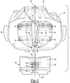
Figure 2 is a top view of the brake assembly with the pad shield removed from the retainer bracket. -
Figure 3 is a top view of the brake assembly with the pad shield installed on the retainer bracket. -
Figure 4 is a perspective view of an example of a retainer bracket. -
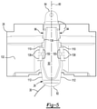
Figure 5 is a bottom view showing the pad shield installed on the retainer bracket. -
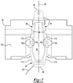
Figures 6-8 illustrate additional examples of pad shields installed on retainer brackets. - As required, detailed embodiments of the present invention are disclosed herein; however, it is to be understood that the disclosed embodiments are merely exemplary of the invention that may be embodied in various and alternative forms. The figures are not necessarily to scale; some features may be exaggerated or minimized to show details of particular components. Therefore, specific structural and functional details disclosed herein are not to be interpreted as limiting, but merely as a representative basis for teaching one skilled in the art to variously employ the present invention.
- Referring to
Figure 1 , an example of abrake assembly 10 is shown. Thebrake assembly 10 may be provided as part of a vehicle, such as a motor vehicle like a truck, bus, farm equipment, military transport or weaponry vehicle, or cargo loading equipment for land, air, or marine vessels. In at least one configuration, thebrake assembly 10 may include abrake carrier 20, ahousing assembly 22, a plurality ofbrake pad assemblies 24, aretainer bracket 26, and apad shield 28. Optionally, acable 30 may also be provided with thebrake assembly 10. - The
brake carrier 20 may facilitate mounting of thebrake assembly 10. For instance, thebrake carrier 20 may be fixedly mounted to a component of the vehicle, such as an axle assembly or a knuckle. Thebrake carrier 20 may receive and support thebrake pad assemblies 24 and may include a rotor opening that may be configured to receive a rotor. As such, thebrake carrier 20 may straddle the rotor and may help position thebrake pad assembly 24 on opposite sides of the rotor. - Referring to
Figures 1 and2 , thehousing assembly 22 may receive various components of thebrake assembly 10. In addition, thehousing assembly 22 may position of the brake pad assemblies 24 with respect to the rotor to facilitate braking of the vehicle. In at least one configuration, thehousing assembly 22 may be mounted to thebrake carrier 20 and may include acaliper housing 40 and acaliper bridge 42. - The
caliper housing 40 may be movably disposed on thebrake carrier 20. For example, thecaliper housing 40 may be slidable along a pair of guide pins that may be fixedly disposed on thebrake carrier 20. Thecaliper housing 40 may receive an actuator, such as at least one piston, that may actuate thebrake pad assembly 24 into engagement with the rotor. For instance, the actuator may actuate a firstbrake pad assembly 24 that is disposed adjacent to thecaliper housing 40 into engagement with the rotor. A reaction force may then move thecaliper housing 40 andcaliper bridge 42 with respect to thebrake carrier 20 to actuate a secondbrake pad assembly 24 that is disposed adjacent to thecaliper bridge 42 into engagement with an opposite side of the rotor to help slow rotation of the rotor and an associated vehicle wheel. Optionally, one or more biasing members, such as retraction springs may be provided to facilitate retraction of the brake pad assemblies 24 away from the rotor when braking is not desired. - The
caliper bridge 42 may be integrally formed with thecaliper housing 40 or may be a separate component that is fixedly mounted to thecaliper housing 40. For example, thecaliper bridge 42 may be coupled or secured to thecaliper housing 40 with one or more fasteners, such as bolts. In at least one configuration, thecaliper bridge 42 may cooperate with thecaliper housing 40 to at least partially define anopening 50, which is best shown inFigure 2 . - The opening 50 may be adapted to receive a
brake pad assembly 24. For instance, thebrake pad assemblies 24 may be installed or inserted into thebrake carrier 20 by inserting a brake pad assembly into theopening 50 when theretainer bracket 26 is removed. Similarly, thebrake pad assembly 24 may be removed from thebrake carrier 20 via theopening 50 when theretainer bracket 26 is removed. The brake pad assemblies 24, thepad shield 28, or combinations thereof may be disposed in the opening 50. - Referring to
Figure 2 , a pair ofbrake pad assemblies 24 may be received in thebrake carrier 20. Thebrake pad assemblies 24 may be disposed on opposite sides of the rotor and may have similar or identical configurations. As such, onebrake pad assembly 24 may be positioned between thecaliper housing 40 and the rotor while the otherbrake pad assembly 24 may be located on the opposite side of the rotor and may be positioned between thecaliper bridge 42 and the rotor. In at least one configuration, abrake pad assembly 24 may include abackplate 60 andfriction material 62. - The
backplate 60 may be a structural member of thebrake pad assembly 24. Thebackplate 60 may be configured as a generally flat plate and may be made of any suitable material, such as a metal alloy. - The
friction material 62 may be disposed on a side of thebackplate 60 that may face toward the rotor. Thefriction material 62 may contact the rotor during vehicle braking. - The
retainer bracket 26 may be securable to thehousing assembly 22. For example, theretainer bracket 26 may be installable and removable from thehousing assembly 22 and may extend across thebrake pad assemblies 24 and the opening 50 in thehousing assembly 22 to help retain thebrake pad assemblies 24 in thebrake carrier 20 when theretainer bracket 26 is secured to thehousing assembly 22. For instance, theretainer bracket 26 may engage or contact abrake pad assembly 24 or may engage or contact apad spring 70, if provided, that may be disposed between thebrake pad assembly 24 and theretainer bracket 26 when theretainer bracket 26 is installed and secured to thehousing assembly 22. - Referring to
Figures 2 and4 , in at least one configuration theretainer bracket 26 may extend along anaxis 80. Theaxis 80 may be oriented to extend between afirst end 82 of theretainer bracket 26 and asecond end 84 of theretainer bracket 26. As such, theretainer bracket 26 and theaxis 80 may extend generally parallel to an axis of rotation of the rotor and may extend generally parallel to the axis along which thebrake pad assemblies 24 are actuatable. - The
first end 82 of theretainer bracket 26 may be mounted to thecaliper housing 40. For instance, thefirst end 82 may contact thecaliper housing 40 and optionally may be received in an opening, notch, or slot in thecaliper housing 40. - The
second end 84 of theretainer bracket 26 may be disposed opposite thefirst end 82. Thesecond end 84 may be disposed on thecaliper bridge 42 and may be secured to thecaliper bridge 42, such as with afastener 86 like a bolt. Thefastener 86 may extend through a hole in theretainer bracket 26. In at least one configuration, thesecond end 84 may be offset from thefirst end 82 in a generally vertical direction such that thesecond end 84 is disposed closer to the axis of rotation of the rotor than thefirst end 82 is. - Referring primarily to
Figures 4 and5 , theretainer bracket 26 may be provided in various configurations. In at least one configuration, theretainer bracket 26 may include atop side 90, abottom side 92, a firstlateral side 94, and a secondlateral side 96. - The
top side 90 may face away from thebrake carrier 20 and thebrake pad assemblies 24. In addition, thetop side 90 may face toward thepad shield 28. Optionally, arecess 100 may extend from thetop side 90 or may be provided in thetop side 90. Therecess 100 may extend toward thebottom side 92 and may provide a gap between thepad shield 28 and thetop side 90. - The
bottom side 92 may be disposed opposite thetop side 90. As such, thebottom side 92 may face toward thebrake pad assemblies 24 and may face away from thepad shield 28. - The first
lateral side 94 may extend between thetop side 90 and thebottom side 92. For instance, the firstlateral side 94 may extend in a generally vertical direction from thetop side 90 to thebottom side 92. In addition, the firstlateral side 94 may extend between thefirst end 82 and thesecond end 84. For example, the firstlateral side 94 may extend from thefirst end 82 toward thesecond end 84, from thesecond end 84 toward thefirst end 82, or from thefirst end 82 to thesecond end 84. - The second
lateral side 96 may be disposed opposite the firstlateral side 94. In addition, the secondlateral side 96 may extend between thetop side 90 and thebottom side 92. For instance, the secondlateral side 96 may extend in a generally vertical direction from thetop side 90 to thebottom side 92. In addition, the secondlateral side 96 may extend between thefirst end 82 and thesecond end 84. For example, the secondlateral side 96 may extend from thefirst end 82 toward thesecond end 84, from thesecond end 84 toward thefirst end 82, or from thefirst end 82 to thesecond end 84. In at least one configuration, the firstlateral side 94, the secondlateral side 96, or both may be spaced apart from therecess 100. - In at least one configuration, the first
lateral side 94 or a portion thereof may be disposed in a nonparallel relationship with the secondlateral side 96. For example, at least a portion of the firstlateral side 94 and the secondlateral side 96 may become further apart from each other or may extend further apart from each other in a first direction. The first direction may extend along theaxis 80 and may be oriented to extend away from thesecond end 84 and toward thefirst end 82 of theretainer bracket 26. The firstlateral side 94 and the secondlateral side 96 may become further apart from each other by orienting the firstlateral side 94, the secondlateral side 96, or both in a nonparallel relationship with theaxis 80. As such, theretainer bracket 26 may increase in width in the first direction. - The first
lateral side 94, the secondlateral side 96, or both may include afirst portion 110 and optionally asecond portion 112. - The
first portion 110 may extend further from theaxis 80 in the first direction or in a direction that extends from thesecond end 84 toward thefirst end 82. InFigure 2 , afirst portion 110 is provided with the firstlateral side 94 and the secondlateral side 96; however, it is contemplated that afirst portion 110 may be provided with only one lateral side. In the configuration shown, thefirst portion 110 of the firstlateral side 94 and thefirst portion 110 of the secondlateral side 96 may be disposed opposite each other and may extend further apart from each other in the first direction. Thefirst portion 110 may have a linear configuration, a nonlinear configuration, or combinations thereof. For instance, thefirst portion 110 may be substantially linear or substantially planar in one or more embodiments. - The
second portion 112 may extend further from theaxis 80 in a second direction that is disposed opposite the first direction or in a direction that extends from thefirst end 82 toward thesecond end 84. InFigure 2 , thesecond portion 112 is provided with the firstlateral side 94 and the secondlateral side 96; however, it is contemplated that a second portion may be provided with only one lateral side or neither lateral sides. In the configuration shown, thesecond portion 112 of the firstlateral side 94 and thesecond portion 112 of the secondlateral side 96 may be disposed opposite each other and may extend closer together in the first direction or further apart in the second direction. Thesecond portion 112 may have a linear configuration, a nonlinear configuration, or combinations thereof. For instance, thesecond portion 112 may be substantially linear or substantially planar in one or more embodiments. In addition, it is contemplated that thesecond portion 112 may not extend further from theaxis 80 in the first direction. For instance, it is contemplated that thesecond portion 112 may extend parallel or substantially parallel to theaxis 80 or may extend further from theaxis 80. - It is contemplated that the first
lateral side 94 and the secondlateral side 96 may be provided with other configurations. For instance, the firstlateral side 94, the secondlateral side 96, or both may not include asecond portion 112. As such, the firstlateral side 94, the secondlateral side 96, or both may extend in a linear manner from thefirst end 82 to thesecond end 84. It is also contemplated that the firstlateral side 94, the secondlateral side 96, or both may extend in a nonlinear manner from thefirst end 82 to thesecond end 84. For instance, the firstlateral side 94, the secondlateral side 96, or both may extend along a curve or an arc between thefirst end 82 and thesecond end 84, some examples of which are shown inFigures 6 and7 . - Referring to
Figure 6 , an example is shown in which at least a portion of the firstlateral side 94 and at least a portion of the secondlateral side 96 is concave. For instance, inFigure 6 at least part of thefirst portions 110 of the firstlateral side 94 and the secondlateral side 96 are illustrated as being concave. - Referring to
Figure 7 , an example is shown in which at least a portion of the firstlateral side 94 and at least a portion of the secondlateral side 96 is convex. For instance, inFigure 7 at least part of thefirst portions 110 of the firstlateral side 94 and the secondlateral side 96 are illustrated as being convex. - Referring to
Figure 8 , another example is shown in which the firstlateral side 94, the secondlateral side 96, or portions thereof may be provided with a staggered profile or step profile. In such a configuration, one ormore steps 120 may be provided with the firstlateral side 94, the secondlateral side 96, or both. Astep 120 may be configured to extend away from theaxis 80 such that the firstlateral side 94, the secondlateral side 96, or both may become wider or extend further from theaxis 80 in the first direction as compared to a region of the lateral side that is disposed closer to thesecond end 84 than thestep 120. For instance, a plurality ofsteps 120 may be provided that may extend progressively further from theaxis 80 in the first direction. Any suitable number of steps may be provided. Moreover, it is contemplated that astep 120 may extend perpendicular with respect to theaxis 80 or in a non-perpendicular manner, such as at oblique angle with respect to theaxis 80, along an arc or curve, or combinations thereof. - Referring to
Figures 2 and3 , thepad shield 28 may extend across theopening 50 in thehousing assembly 22. Thepad shield 28 may help protect thebrake pad assemblies 24 from environmental contaminants. Thepad shield 28 may be made of any suitable material, such as a metal alloy like stainless steel, carbon fiber, or a polymeric material. - The
pad shield 28 may be secured to theretainer bracket 26. More specifically, thepad shield 28 may be installable on theretainer bracket 26 and may be removable from theretainer bracket 26 when theretainer bracket 26 is secured to thehousing assembly 22. As such, thepad shield 28 may not be secured underneath theretainer bracket 26 in a manner that requires theretainer bracket 26 to be disassembled from thehousing assembly 22 to either install thepad shield 28 on thebrake assembly 10 or remove thepad shield 28 from thebrake assembly 10. In at least one configuration such as is best shown inFigure 2 , thepad shield 28 may have afirst side 130, asecond side 132, a firstlongitudinal edge 134, a secondlongitudinal edge 136, and a set of retaining features 138. Optionally, thepad shield 28 may include one ormore openings 140. - The
first side 130 may face away from thebrake carrier 20 and thebrake pad assemblies 24. In addition, thefirst side 130 or a portion thereof may face away from theretainer bracket 26. - The
second side 132 may be disposed opposite thefirst side 130. As such, thesecond side 132 may face toward thebrake pad assembly 24 and theretainer bracket 26. - The first
longitudinal edge 134 may face toward thecaliper housing 40. The firstlongitudinal edge 134 may extend in a generally vertical direction from thefirst side 130 toward or to thesecond side 132. - The second
longitudinal edge 136 may be disposed opposite the firstlongitudinal edge 134. As such, the secondlongitudinal edge 136 may face toward thecaliper bridge 42. The secondlongitudinal edge 136 may extend in a generally vertical direction from thefirst side 130 toward or to thesecond side 132. - Referring to
Figures 2 and5 , a set of retainingfeatures 138 may couple thepad shield 28 to theretainer bracket 26. The retaining features 138 may extend from thesecond side 132 of thepad shield 28 toward theretainer bracket 26 and may engage theretainer bracket 26 in a manner that secures thepad shield 28 to theretainer bracket 26. In at least one configuration, the retaining features 138 may extend along the firstlateral side 94, the secondlateral side 96, or both and may grasp or hook onto theretainer bracket 26. For instance, a retainingfeature 138 may have a barb or ahook 150 that may be disposed at a distal end of the retainingfeature 138. Thehook 150 may extend in an inward direction toward theretainer bracket 26 or toward a plane in which theaxis 80 and the rotor axis may be disposed. Ahook 150 may wrap around a lateral side of theretainer bracket 26 and may engage or contact thebottom side 92 of theretainer bracket 26. - A retaining
feature 138 may be generally aligned with a lateral side. For instance, a first member of the set of retaining features or afirst retaining feature 138 may be disposed proximate and may engage the firstlateral side 94 while a second member of the set of retaining features or asecond retaining feature 138 may be disposed proximate and may engage the secondlateral side 96. The first and second retaining features 138, 138 may be aligned with each other or disposed directly opposite each other and on opposite sides of theaxis 80. It is also contemplated that retaining features may be staggered such that a retaining feature is not aligned with or disposed opposite another retaining feature. - A plurality of retaining
features 138 may be provided that may be spaced apart from each other and that may be aligned with the firstlateral side 94. Similarly, a plurality of retainingfeatures 138 may be provided that may be spaced apart from each other and that may be aligned with the secondlateral side 96. A retainingfeature 138 may be positioned above thefriction material 62 and away from tabs or protrusions that extend upward from thebackplate 60 so as not to interfere with actuation of thebrake pad assemblies 24. - In at least one configuration, some or all of the members of the set of retaining
features 138 may be disposed in a nonparallel relationship with theaxis 80. For instance, in the configuration shown inFigure 5 , three retainingfeatures 138 are aligned with the firstlateral side 94 and three other retaining features 138 are aligned with the secondlateral side 96; however, it is contemplated that a greater or lesser number of retaining features 138 may be provided or may be oriented differently. One or more retaining features 138 that are aligned with the firstlateral side 94 may be disposed directly opposite acorresponding retaining feature 138 that may be aligned with the secondlateral side 96. In such a configuration, one or more retaining features 138 that are disposed closer to thefirst end 82 of theretainer bracket 26 may be disposed further from theaxis 80 than one or more retaining features 138 that are disposed closer to thesecond end 84. In at least one configuration, the retaining features 138 that are aligned with the firstlateral side 94 may be disposed substantially parallel to each other, the retaining features 138 that are aligned with the secondlateral side 96 may be disposed substantially parallel to each other, or both. Moreover, one or more retaining features 138 that are aligned with the firstlateral side 94 may be disposed in a nonparallel relationship with one or more retaining features 138 that are aligned with the secondlateral side 96. - Retaining features 138 may or may not be disposed along a curve or an arc and may or may not be disposed substantially parallel to each other when a corresponding lateral side extends along a curve or an arc as shown in
Figures 6 and7 . - Referring to
Figure 8 , retaining features 138 may also be provided with a staggered profile or a step profile. In such a configuration, retainingfeatures 138 may be aligned with acorresponding step 120 of theretainer bracket 26. In a configuration in which theretainer bracket 26 has multiple steps, the retaining features 138 may be arranged such that retaining features 138 may be arranged further from theaxis 80 in the first direction. - Referring to
Figure 2 , one ormore openings 140 may optionally be provided in thepad shield 28 that may extend from thefirst side 130 to thesecond side 132. In at least one configuration, theopenings 140 may be axially positioned between the firstlongitudinal edge 134 and the secondlongitudinal edge 136. Moreover, theopenings 140 may be positioned above theretainer bracket 26 and thus may be at least partially blocked or closed by theretainer bracket 26 when thepad shield 28 is installed on theretainer bracket 26. - The
pad shield 28 may be installed on theretainer bracket 26 in various ways. - As one example, the
pad shield 28 may be slid along an installedretainer bracket 26 to install or remove thepad shield 28. For instance, thepad shield 28 may be positioned adjacent to thecaliper bridge 42 or over thecaliper bridge 42 like what is shown inFigure 2 such that thesecond side 132 of thepad shield 28 may be generally aligned with thetop side 90 of theretainer bracket 26 and such that hooks 150 of the retaining features 138 may be generally aligned with thebottom side 92 of theretainer bracket 26. In addition, thepad shield 28 may be roughly aligned with theaxis 80. Next, thepad shield 28 may be slid along theretainer bracket 26 or slid along theaxis 80 toward thecaliper housing 40 and thefirst end 82 of theretainer bracket 26. Once thepad shield 26 has been slid a sufficient distance, the retaining features 138 may engage or contact a corresponding side of theretainer bracket 26, such as the firstlateral side 94 or the secondlateral side 96. Moreover, thehooks 150 may engage or contact thebottom side 92 of theretainer bracket 26, thereby securing thepad shield 28 to theretainer bracket 26. Thepad shield 28 may be removed from theretainer bracket 26 by sliding thepad shield 28 in the opposite direction or away from thecaliper housing 40. - It is also contemplated that the
pad shield 28 may be installed on or slid onto theretainer bracket 26 prior to attaching theretainer bracket 26 to thehousing assembly 22 and then theretainer bracket 26 may be mounted to thehousing assembly 22. Once theretainer bracket 26 is mounted, thepad shield 28 may be slid off of and slid back onto theretainer bracket 26 without disassembling theretainer bracket 26 from thehousing assembly 22. - As another example, the
pad shield 28, retaining features 138, or both may be configured to flex such that thepad shield 28 may be snap fit to theretainer bracket 26. For instance, thepad shield 28 may be positioned over thetop side 90 of theretainer bracket 26 and then may be moved toward thetop side 90 and theopening 50. Thepad shield 28 and/or the retaining features 138 may then flex away from theaxis 80 and slide along the firstlateral side 94 and the secondlateral side 96. Thepad shield 28 and/or the retaining features 138 may then flex toward theaxis 80 and may engage thebottom side 92 of theretainer bracket 26 when ahook 150 reaches thebottom side 92 or reaches an end of a corresponding lateral side, thereby securing thepad shield 28 on theretainer bracket 26. Thepad shield 28 may be removed by exerting sufficient force away from thetop side 90 of theretainer bracket 26 to disengage the retaining features 138 from theretainer bracket 26 or by sliding thepad shield 28 away from thecaliper housing 40 as previously described. - Optionally, a
cable 30 may be disposed between theretainer bracket 26 and thepad shield 28. As such, theretainer bracket 26 and thepad shield 28 may cooperate to help position and retain thecable 30. In at least one configuration, thecable 30 may be received in therecess 100 in theretainer bracket 26. Thecable 30 may be of any suitable type and may facilitate an electrical connection between a sensor and a controller or control module. In at least one configuration, the sensor may be disposed on thebrake assembly 10 and may be of any suitable type. For instance, the sensor may be a temperature sensor, speed sensor, antilock brake sensor, brake pad position sensor, brake pad wear sensor, or the like. Thecable 30 may fit between theretainer bracket 26 and thepad shield 28 with a clearance fit or an interference fit. - The brake assembly configurations described above may allow a pad shield to be installed onto and/or removed from a retainer bracket when a retainer bracket is already installed on the brake assembly. As such, a pad shield may be installed without removing the retainer bracket from the housing assembly, which may allow the brake pad assemblies to remain in a secure installed position underneath the retainer bracket. In addition, the pad shield may be installed without removing the retainer bracket, then positioning the pad shield in the opening, and then reinstalling the retainer bracket over the pad shield, which may reduce assembly time and associated costs. Similarly, a pad shield may be removed without removing the retainer bracket from the housing assembly. Accordingly, ease of assembly and disassembly of the pad shield may be improved, such as when the brake assembly is installed on a vehicle. For instance, a pad shield may be easier to install or remove in the limited space around the brake assembly when the brake assembly is installed on a vehicle. Moreover, a pad shield may be installable or removable without removing a vehicle wheel in some situations. The pad shield may be installed without separate additional fasteners, such as a threaded fastener like a bolt that may fasten the pad shield to the retainer bracket, thereby reducing the number of parts, manufacturing costs, and simplifying assembly.
- While exemplary embodiments are described above, it is not intended that these embodiments describe all possible forms of the invention. Rather, the words used in the specification are words of description rather than limitation, and it is understood that various changes may be made without departing from the spirit and scope of the invention. Additionally, the features of various implementing embodiments may be combined to form further embodiments of the invention.
Claims (15)
- A brake assembly comprising:a housing assembly that defines an opening that is adapted to receive a brake pad assembly;a retainer bracket that is secured to the housing assembly and extends across the opening; anda pad shield that extends across the opening and is secured to the retainer bracket, wherein the pad shield is installable onto the retainer bracket and removable from the retainer bracket when the retainer bracket extends across the opening and is secured to the housing assembly.
- The brake assembly of claim 1 wherein the pad shield has a set of retaining features that couple the pad shield to the retainer bracket, preferably the set of retaining features extend to a bottom side of the retainer bracket that faces away from the pad shield.
- The brake assembly of any preceding claim wherein the pad shield has a set of retaining features that couple the pad shield to the retainer bracket and the retainer bracket includes a top side that faces toward the pad shield, a bottom side disposed opposite the top side, a first lateral side that extends between the top side and the bottom side, and a second lateral side that is disposed opposite the first lateral side and that extends between the top side and the bottom side, wherein a first member of the set of retaining features is disposed proximate the first lateral side and a second member of the set of retaining features is disposed proximate the second lateral side.
- The brake assembly of any preceding claim wherein the retainer bracket extends along an axis that extends from a first end of the retainer bracket toward a second end of the retainer bracket that is disposed opposite the first end.
- The brake assembly of claim 4 dependent on claim 2 or claim 3 wherein at least some members of the set of retaining features are disposed in a nonparallel relationship with the axis.
- The brake assembly of claim 3 or claim 5 dependent on claim 3 wherein a third member of the set of retaining features is disposed proximate the first lateral side, and a fourth member of the set of retaining features is disposed proximate the second lateral side, the third member and the fourth member are disposed closer to a first end of the retainer bracket than the first member and the second member, and the third member and the fourth member are disposed further from the axis than the first member and the second member.
- The brake assembly of claim 6 wherein the first member is disposed substantially parallel to the third member and the second member is disposed substantially parallel to the fourth member, preferably the first member and the third member are disposed in a nonparallel relationship with the second member and the fourth member.
- The brake assembly of any preceding claim wherein the housing assembly includes a caliper housing and a caliper bridge secured to the caliper housing, wherein the caliper housing and the caliper bridge cooperate to define the opening and wherein a first end of the retainer bracket is disposed on the caliper housing and a second end of the retainer bracket is disposed on the caliper bridge.
- The brake assembly of any preceding claim dependent on claim 3 wherein at least a portion of the first lateral side is disposed in a nonparallel relationship with the second lateral side.
- The brake assembly of any preceding claim dependent on claim 3 wherein the first lateral side and the second lateral side have first portions that are disposed opposite each other and that extend further apart from each other in a first direction that extends along the axis from the second end toward the first end, preferably the first lateral side and the second lateral side have second portions that are disposed opposite the each other and that extend further apart from each other in a second direction that extends along the axis from the first end toward the second end.
- The brake assembly of any preceding claim wherein a cable is disposed between the retainer bracket and the pad shield, preferably the retainer bracket includes a recess that extends from a top side of the retainer bracket that faces toward the pad shield, wherein the cable is received in the recess.
- A method of assembling a brake assembly, comprising:providing a housing assembly that has an opening;positioning a retainer bracket on the housing assembly such that the retainer bracket extends across the opening;securing the retainer bracket to the housing assembly such that the retainer bracket does not move with respect to the housing assembly; andinstalling a pad shield on the retainer bracket after the retainer bracket is secured to the housing assembly.
- The method of claim 12 wherein a cable is secured between the retainer bracket and the pad shield when the pad shield is installed.
- The method of claim 12 or claim 13 wherein the housing assembly includes a caliper housing and a caliper bridge secured to the caliper housing, the retainer bracket has a first end that is disposed on the caliper housing and a second end that is disposed opposite the first end and is disposed on the caliper bridge, and wherein installing the pad shield includes sliding the pad shield along the retainer bracket in a first direction that extends from the second end toward the first end, preferably the pad shield is removable from the retainer bracket by sliding the pad shield along the retainer bracket in a second direction that extends from the first end toward the second end while the retainer bracket remains secured to the housing assembly.
- The method of any one of claims 12-14 wherein the retainer bracket increases in width in a direction that extends from a second end to a first end.
Applications Claiming Priority (1)
| Application Number | Priority Date | Filing Date | Title |
|---|---|---|---|
| US16/930,169 US11555524B2 (en) | 2020-07-15 | 2020-07-15 | Brake assembly having a pad shield and method of assembly |
Publications (2)
| Publication Number | Publication Date |
|---|---|
| EP3940258A1 true EP3940258A1 (en) | 2022-01-19 |
| EP3940258B1 EP3940258B1 (en) | 2023-09-20 |
Family
ID=76890937
Family Applications (1)
| Application Number | Title | Priority Date | Filing Date |
|---|---|---|---|
| EP21185163.9A Active EP3940258B1 (en) | 2020-07-15 | 2021-07-12 | Brake assembly having a pad shield and method of assembly |
Country Status (2)
| Country | Link |
|---|---|
| US (1) | US11555524B2 (en) |
| EP (1) | EP3940258B1 (en) |
Families Citing this family (1)
| Publication number | Priority date | Publication date | Assignee | Title |
|---|---|---|---|---|
| US12590613B2 (en) * | 2023-10-24 | 2026-03-31 | Bendix Commercial Vehicle Systems Llc | Pad shield for disc brake system and methods for the use and assembly thereof |
Citations (6)
| Publication number | Priority date | Publication date | Assignee | Title |
|---|---|---|---|---|
| US20080110707A1 (en) * | 2006-11-15 | 2008-05-15 | Bendix Spicer Foundation Brake Llc | Pad shield |
| US20140158482A1 (en) * | 2012-12-11 | 2014-06-12 | Arvinmeritor Technology, Llc | Brake caliper assembly having a spacer tape and a method of manufacture |
| WO2014097098A1 (en) * | 2012-12-20 | 2014-06-26 | Freni Brembo S.P.A. | Caliper for disc brake |
| US8857575B2 (en) | 2012-12-11 | 2014-10-14 | Arvinmeritor Technology, Llc | Brake caliper assembly having a pad shield |
| US20160146278A1 (en) * | 2014-11-20 | 2016-05-26 | Meritor Heavy Vehicle Braking Systems (Uk) Limited | Disc Brake Assembly |
| US20190162259A1 (en) * | 2017-11-29 | 2019-05-30 | Meritor Heavy Vehicle Braking Systems (Uk) Limited | Disc brake |
Family Cites Families (6)
| Publication number | Priority date | Publication date | Assignee | Title |
|---|---|---|---|---|
| SE0203442L (en) * | 2002-11-21 | 2003-10-28 | Scania Cv Abp | Protective cover for disc brake and disc brake unit including such protective cover unit |
| DE102009023104C5 (en) * | 2008-06-05 | 2013-08-22 | Wabco Radbremsen Gmbh | Disc brake, in particular for commercial vehicles, and covering such a disc brake |
| USD645802S1 (en) * | 2011-04-14 | 2011-09-27 | Wabco Gmbh | Disk brake dust shield |
| EP2835553B1 (en) * | 2013-08-07 | 2018-04-25 | Meritor Heavy Vehicle Braking Systems (UK) Limited | Disc brake assembly |
| US10309470B1 (en) | 2018-03-02 | 2019-06-04 | Arvinmeritor Technology, Llc | Brake caliper assembly having a retainer bracket |
| US11143255B2 (en) * | 2019-05-09 | 2021-10-12 | Arvinmeritor Technology, Llc | Brake assembly having a retraction spring and method of assembly |
-
2020
- 2020-07-15 US US16/930,169 patent/US11555524B2/en active Active
-
2021
- 2021-07-12 EP EP21185163.9A patent/EP3940258B1/en active Active
Patent Citations (6)
| Publication number | Priority date | Publication date | Assignee | Title |
|---|---|---|---|---|
| US20080110707A1 (en) * | 2006-11-15 | 2008-05-15 | Bendix Spicer Foundation Brake Llc | Pad shield |
| US20140158482A1 (en) * | 2012-12-11 | 2014-06-12 | Arvinmeritor Technology, Llc | Brake caliper assembly having a spacer tape and a method of manufacture |
| US8857575B2 (en) | 2012-12-11 | 2014-10-14 | Arvinmeritor Technology, Llc | Brake caliper assembly having a pad shield |
| WO2014097098A1 (en) * | 2012-12-20 | 2014-06-26 | Freni Brembo S.P.A. | Caliper for disc brake |
| US20160146278A1 (en) * | 2014-11-20 | 2016-05-26 | Meritor Heavy Vehicle Braking Systems (Uk) Limited | Disc Brake Assembly |
| US20190162259A1 (en) * | 2017-11-29 | 2019-05-30 | Meritor Heavy Vehicle Braking Systems (Uk) Limited | Disc brake |
Also Published As
| Publication number | Publication date |
|---|---|
| US11555524B2 (en) | 2023-01-17 |
| EP3940258B1 (en) | 2023-09-20 |
| US20220018408A1 (en) | 2022-01-20 |
Similar Documents
| Publication | Publication Date | Title |
|---|---|---|
| EP2743533B1 (en) | Brake calliper assembly having a pad shield | |
| EP3865726B1 (en) | Brake assembly having a retraction spring | |
| US11078974B2 (en) | Disc brake for a commercial vehicle | |
| EP3023666B1 (en) | Disc brake assembly | |
| EP3534030B1 (en) | Brake caliper assembly having a retainer bracket | |
| EP2807393B1 (en) | Clip for use in a disc brake assembly and disc brake assembly including such a clip | |
| EP3250839B1 (en) | Pad and spring assembly for a disc brake caliper | |
| EP3736462B1 (en) | Brake assembly having a retraction spring and method of assembly | |
| KR100619536B1 (en) | Brake shoe and brake assembly | |
| EP3940258B1 (en) | Brake assembly having a pad shield and method of assembly | |
| US9863492B2 (en) | Brake lining mounting for a disc brake | |
| EP3551904A1 (en) | Brake clip for disc brake assembly and disc brake assembly including such a brake clip | |
| EP3150878B1 (en) | Brake assembly having a bridge | |
| EP3032125B1 (en) | Disc brake and components thereof | |
| US6962243B2 (en) | Multi-disc brake system | |
| EP1744068A1 (en) | Fastener retention mechanism | |
| EP4290094A1 (en) | Rotor clip for brake assembly | |
| EP4729799A1 (en) | Brake assembly having guide pin assembly | |
| US7527129B2 (en) | Brake carrier having improved electromechanical actuator and mounting arrangement therefor | |
| EP3772600A1 (en) | Brake assembly having an actuator mount | |
| EP4102092A1 (en) | Disc brake assembly having a sensor assembly | |
| WO2025090303A1 (en) | Pad shield for disc brake system and methods for the use and assembly thereof | |
| GB2361969A (en) | Resilient mounting for an axially moveable brake disc |
Legal Events
| Date | Code | Title | Description |
|---|---|---|---|
| PUAI | Public reference made under article 153(3) epc to a published international application that has entered the european phase |
Free format text: ORIGINAL CODE: 0009012 |
|
| STAA | Information on the status of an ep patent application or granted ep patent |
Free format text: STATUS: THE APPLICATION HAS BEEN PUBLISHED |
|
| AK | Designated contracting states |
Kind code of ref document: A1 Designated state(s): AL AT BE BG CH CY CZ DE DK EE ES FI FR GB GR HR HU IE IS IT LI LT LU LV MC MK MT NL NO PL PT RO RS SE SI SK SM TR |
|
| STAA | Information on the status of an ep patent application or granted ep patent |
Free format text: STATUS: REQUEST FOR EXAMINATION WAS MADE |
|
| 17P | Request for examination filed |
Effective date: 20220718 |
|
| RBV | Designated contracting states (corrected) |
Designated state(s): AL AT BE BG CH CY CZ DE DK EE ES FI FR GB GR HR HU IE IS IT LI LT LU LV MC MK MT NL NO PL PT RO RS SE SI SK SM TR |
|
| GRAP | Despatch of communication of intention to grant a patent |
Free format text: ORIGINAL CODE: EPIDOSNIGR1 |
|
| STAA | Information on the status of an ep patent application or granted ep patent |
Free format text: STATUS: GRANT OF PATENT IS INTENDED |
|
| INTG | Intention to grant announced |
Effective date: 20230209 |
|
| GRAJ | Information related to disapproval of communication of intention to grant by the applicant or resumption of examination proceedings by the epo deleted |
Free format text: ORIGINAL CODE: EPIDOSDIGR1 |
|
| STAA | Information on the status of an ep patent application or granted ep patent |
Free format text: STATUS: REQUEST FOR EXAMINATION WAS MADE |
|
| INTC | Intention to grant announced (deleted) | ||
| GRAP | Despatch of communication of intention to grant a patent |
Free format text: ORIGINAL CODE: EPIDOSNIGR1 |
|
| STAA | Information on the status of an ep patent application or granted ep patent |
Free format text: STATUS: GRANT OF PATENT IS INTENDED |
|
| INTG | Intention to grant announced |
Effective date: 20230601 |
|
| P01 | Opt-out of the competence of the unified patent court (upc) registered |
Effective date: 20230531 |
|
| GRAS | Grant fee paid |
Free format text: ORIGINAL CODE: EPIDOSNIGR3 |
|
| GRAA | (expected) grant |
Free format text: ORIGINAL CODE: 0009210 |
|
| STAA | Information on the status of an ep patent application or granted ep patent |
Free format text: STATUS: THE PATENT HAS BEEN GRANTED |
|
| AK | Designated contracting states |
Kind code of ref document: B1 Designated state(s): AL AT BE BG CH CY CZ DE DK EE ES FI FR GB GR HR HU IE IS IT LI LT LU LV MC MK MT NL NO PL PT RO RS SE SI SK SM TR |
|
| REG | Reference to a national code |
Ref country code: GB Ref legal event code: FG4D |
|
| REG | Reference to a national code |
Ref country code: CH Ref legal event code: EP |
|
| REG | Reference to a national code |
Ref country code: DE Ref legal event code: R096 Ref document number: 602021005242 Country of ref document: DE |
|
| REG | Reference to a national code |
Ref country code: IE Ref legal event code: FG4D |
|
| REG | Reference to a national code |
Ref country code: SE Ref legal event code: TRGR |
|
| REG | Reference to a national code |
Ref country code: LT Ref legal event code: MG9D |
|
| PG25 | Lapsed in a contracting state [announced via postgrant information from national office to epo] |
Ref country code: GR Free format text: LAPSE BECAUSE OF FAILURE TO SUBMIT A TRANSLATION OF THE DESCRIPTION OR TO PAY THE FEE WITHIN THE PRESCRIBED TIME-LIMIT Effective date: 20231221 |
|
| REG | Reference to a national code |
Ref country code: NL Ref legal event code: MP Effective date: 20230920 |
|
| PG25 | Lapsed in a contracting state [announced via postgrant information from national office to epo] |
Ref country code: RS Free format text: LAPSE BECAUSE OF FAILURE TO SUBMIT A TRANSLATION OF THE DESCRIPTION OR TO PAY THE FEE WITHIN THE PRESCRIBED TIME-LIMIT Effective date: 20230920 Ref country code: NO Free format text: LAPSE BECAUSE OF FAILURE TO SUBMIT A TRANSLATION OF THE DESCRIPTION OR TO PAY THE FEE WITHIN THE PRESCRIBED TIME-LIMIT Effective date: 20231220 Ref country code: LV Free format text: LAPSE BECAUSE OF FAILURE TO SUBMIT A TRANSLATION OF THE DESCRIPTION OR TO PAY THE FEE WITHIN THE PRESCRIBED TIME-LIMIT Effective date: 20230920 Ref country code: LT Free format text: LAPSE BECAUSE OF FAILURE TO SUBMIT A TRANSLATION OF THE DESCRIPTION OR TO PAY THE FEE WITHIN THE PRESCRIBED TIME-LIMIT Effective date: 20230920 Ref country code: HR Free format text: LAPSE BECAUSE OF FAILURE TO SUBMIT A TRANSLATION OF THE DESCRIPTION OR TO PAY THE FEE WITHIN THE PRESCRIBED TIME-LIMIT Effective date: 20230920 Ref country code: GR Free format text: LAPSE BECAUSE OF FAILURE TO SUBMIT A TRANSLATION OF THE DESCRIPTION OR TO PAY THE FEE WITHIN THE PRESCRIBED TIME-LIMIT Effective date: 20231221 Ref country code: FI Free format text: LAPSE BECAUSE OF FAILURE TO SUBMIT A TRANSLATION OF THE DESCRIPTION OR TO PAY THE FEE WITHIN THE PRESCRIBED TIME-LIMIT Effective date: 20230920 |
|
| REG | Reference to a national code |
Ref country code: AT Ref legal event code: MK05 Ref document number: 1613600 Country of ref document: AT Kind code of ref document: T Effective date: 20230920 |
|
| PG25 | Lapsed in a contracting state [announced via postgrant information from national office to epo] |
Ref country code: NL Free format text: LAPSE BECAUSE OF FAILURE TO SUBMIT A TRANSLATION OF THE DESCRIPTION OR TO PAY THE FEE WITHIN THE PRESCRIBED TIME-LIMIT Effective date: 20230920 |
|
| PG25 | Lapsed in a contracting state [announced via postgrant information from national office to epo] |
Ref country code: IS Free format text: LAPSE BECAUSE OF FAILURE TO SUBMIT A TRANSLATION OF THE DESCRIPTION OR TO PAY THE FEE WITHIN THE PRESCRIBED TIME-LIMIT Effective date: 20240120 |
|
| PG25 | Lapsed in a contracting state [announced via postgrant information from national office to epo] |
Ref country code: AT Free format text: LAPSE BECAUSE OF FAILURE TO SUBMIT A TRANSLATION OF THE DESCRIPTION OR TO PAY THE FEE WITHIN THE PRESCRIBED TIME-LIMIT Effective date: 20230920 |
|
| PG25 | Lapsed in a contracting state [announced via postgrant information from national office to epo] |
Ref country code: ES Free format text: LAPSE BECAUSE OF FAILURE TO SUBMIT A TRANSLATION OF THE DESCRIPTION OR TO PAY THE FEE WITHIN THE PRESCRIBED TIME-LIMIT Effective date: 20230920 |
|
| PG25 | Lapsed in a contracting state [announced via postgrant information from national office to epo] |
Ref country code: SM Free format text: LAPSE BECAUSE OF FAILURE TO SUBMIT A TRANSLATION OF THE DESCRIPTION OR TO PAY THE FEE WITHIN THE PRESCRIBED TIME-LIMIT Effective date: 20230920 Ref country code: RO Free format text: LAPSE BECAUSE OF FAILURE TO SUBMIT A TRANSLATION OF THE DESCRIPTION OR TO PAY THE FEE WITHIN THE PRESCRIBED TIME-LIMIT Effective date: 20230920 Ref country code: IS Free format text: LAPSE BECAUSE OF FAILURE TO SUBMIT A TRANSLATION OF THE DESCRIPTION OR TO PAY THE FEE WITHIN THE PRESCRIBED TIME-LIMIT Effective date: 20240120 Ref country code: ES Free format text: LAPSE BECAUSE OF FAILURE TO SUBMIT A TRANSLATION OF THE DESCRIPTION OR TO PAY THE FEE WITHIN THE PRESCRIBED TIME-LIMIT Effective date: 20230920 Ref country code: EE Free format text: LAPSE BECAUSE OF FAILURE TO SUBMIT A TRANSLATION OF THE DESCRIPTION OR TO PAY THE FEE WITHIN THE PRESCRIBED TIME-LIMIT Effective date: 20230920 Ref country code: CZ Free format text: LAPSE BECAUSE OF FAILURE TO SUBMIT A TRANSLATION OF THE DESCRIPTION OR TO PAY THE FEE WITHIN THE PRESCRIBED TIME-LIMIT Effective date: 20230920 Ref country code: AT Free format text: LAPSE BECAUSE OF FAILURE TO SUBMIT A TRANSLATION OF THE DESCRIPTION OR TO PAY THE FEE WITHIN THE PRESCRIBED TIME-LIMIT Effective date: 20230920 Ref country code: SK Free format text: LAPSE BECAUSE OF FAILURE TO SUBMIT A TRANSLATION OF THE DESCRIPTION OR TO PAY THE FEE WITHIN THE PRESCRIBED TIME-LIMIT Effective date: 20230920 Ref country code: PT Free format text: LAPSE BECAUSE OF FAILURE TO SUBMIT A TRANSLATION OF THE DESCRIPTION OR TO PAY THE FEE WITHIN THE PRESCRIBED TIME-LIMIT Effective date: 20240122 |
|
| PG25 | Lapsed in a contracting state [announced via postgrant information from national office to epo] |
Ref country code: PL Free format text: LAPSE BECAUSE OF FAILURE TO SUBMIT A TRANSLATION OF THE DESCRIPTION OR TO PAY THE FEE WITHIN THE PRESCRIBED TIME-LIMIT Effective date: 20230920 Ref country code: IT Free format text: LAPSE BECAUSE OF FAILURE TO SUBMIT A TRANSLATION OF THE DESCRIPTION OR TO PAY THE FEE WITHIN THE PRESCRIBED TIME-LIMIT Effective date: 20230920 |
|
| REG | Reference to a national code |
Ref country code: DE Ref legal event code: R097 Ref document number: 602021005242 Country of ref document: DE |
|
| PG25 | Lapsed in a contracting state [announced via postgrant information from national office to epo] |
Ref country code: DK Free format text: LAPSE BECAUSE OF FAILURE TO SUBMIT A TRANSLATION OF THE DESCRIPTION OR TO PAY THE FEE WITHIN THE PRESCRIBED TIME-LIMIT Effective date: 20230920 |
|
| PLBE | No opposition filed within time limit |
Free format text: ORIGINAL CODE: 0009261 |
|
| STAA | Information on the status of an ep patent application or granted ep patent |
Free format text: STATUS: NO OPPOSITION FILED WITHIN TIME LIMIT |
|
| PG25 | Lapsed in a contracting state [announced via postgrant information from national office to epo] |
Ref country code: DK Free format text: LAPSE BECAUSE OF FAILURE TO SUBMIT A TRANSLATION OF THE DESCRIPTION OR TO PAY THE FEE WITHIN THE PRESCRIBED TIME-LIMIT Effective date: 20230920 |
|
| 26N | No opposition filed |
Effective date: 20240621 |
|
| PG25 | Lapsed in a contracting state [announced via postgrant information from national office to epo] |
Ref country code: SI Free format text: LAPSE BECAUSE OF FAILURE TO SUBMIT A TRANSLATION OF THE DESCRIPTION OR TO PAY THE FEE WITHIN THE PRESCRIBED TIME-LIMIT Effective date: 20230920 |
|
| PG25 | Lapsed in a contracting state [announced via postgrant information from national office to epo] |
Ref country code: SI Free format text: LAPSE BECAUSE OF FAILURE TO SUBMIT A TRANSLATION OF THE DESCRIPTION OR TO PAY THE FEE WITHIN THE PRESCRIBED TIME-LIMIT Effective date: 20230920 |
|
| PG25 | Lapsed in a contracting state [announced via postgrant information from national office to epo] |
Ref country code: BG Free format text: LAPSE BECAUSE OF FAILURE TO SUBMIT A TRANSLATION OF THE DESCRIPTION OR TO PAY THE FEE WITHIN THE PRESCRIBED TIME-LIMIT Effective date: 20230920 |
|
| PG25 | Lapsed in a contracting state [announced via postgrant information from national office to epo] |
Ref country code: BG Free format text: LAPSE BECAUSE OF FAILURE TO SUBMIT A TRANSLATION OF THE DESCRIPTION OR TO PAY THE FEE WITHIN THE PRESCRIBED TIME-LIMIT Effective date: 20230920 |
|
| PG25 | Lapsed in a contracting state [announced via postgrant information from national office to epo] |
Ref country code: MC Free format text: LAPSE BECAUSE OF FAILURE TO SUBMIT A TRANSLATION OF THE DESCRIPTION OR TO PAY THE FEE WITHIN THE PRESCRIBED TIME-LIMIT Effective date: 20230920 |
|
| REG | Reference to a national code |
Ref country code: CH Ref legal event code: PL |
|
| PG25 | Lapsed in a contracting state [announced via postgrant information from national office to epo] |
Ref country code: LU Free format text: LAPSE BECAUSE OF NON-PAYMENT OF DUE FEES Effective date: 20240712 |
|
| PG25 | Lapsed in a contracting state [announced via postgrant information from national office to epo] |
Ref country code: LU Free format text: LAPSE BECAUSE OF NON-PAYMENT OF DUE FEES Effective date: 20240712 |
|
| PG25 | Lapsed in a contracting state [announced via postgrant information from national office to epo] |
Ref country code: BE Free format text: LAPSE BECAUSE OF NON-PAYMENT OF DUE FEES Effective date: 20240731 Ref country code: CH Free format text: LAPSE BECAUSE OF NON-PAYMENT OF DUE FEES Effective date: 20240731 |
|
| REG | Reference to a national code |
Ref country code: BE Ref legal event code: MM Effective date: 20240731 |
|
| PG25 | Lapsed in a contracting state [announced via postgrant information from national office to epo] |
Ref country code: IE Free format text: LAPSE BECAUSE OF NON-PAYMENT OF DUE FEES Effective date: 20240712 |
|
| PGFP | Annual fee paid to national office [announced via postgrant information from national office to epo] |
Ref country code: DE Payment date: 20250729 Year of fee payment: 5 |
|
| PGFP | Annual fee paid to national office [announced via postgrant information from national office to epo] |
Ref country code: FR Payment date: 20250725 Year of fee payment: 5 |
|
| PGFP | Annual fee paid to national office [announced via postgrant information from national office to epo] |
Ref country code: SE Payment date: 20250727 Year of fee payment: 5 |
|
| PG25 | Lapsed in a contracting state [announced via postgrant information from national office to epo] |
Ref country code: CY Free format text: LAPSE BECAUSE OF FAILURE TO SUBMIT A TRANSLATION OF THE DESCRIPTION OR TO PAY THE FEE WITHIN THE PRESCRIBED TIME-LIMIT; INVALID AB INITIO Effective date: 20210712 |
|
| PG25 | Lapsed in a contracting state [announced via postgrant information from national office to epo] |
Ref country code: HU Free format text: LAPSE BECAUSE OF FAILURE TO SUBMIT A TRANSLATION OF THE DESCRIPTION OR TO PAY THE FEE WITHIN THE PRESCRIBED TIME-LIMIT; INVALID AB INITIO Effective date: 20210712 |
|
| GBPC | Gb: european patent ceased through non-payment of renewal fee |
Effective date: 20250712 |
|
| PG25 | Lapsed in a contracting state [announced via postgrant information from national office to epo] |
Ref country code: GB Free format text: LAPSE BECAUSE OF NON-PAYMENT OF DUE FEES Effective date: 20250712 |
|
| PG25 | Lapsed in a contracting state [announced via postgrant information from national office to epo] |
Ref country code: TR Free format text: LAPSE BECAUSE OF FAILURE TO SUBMIT A TRANSLATION OF THE DESCRIPTION OR TO PAY THE FEE WITHIN THE PRESCRIBED TIME-LIMIT Effective date: 20230920 |