EP3940243A1 - Air inflator device - Google Patents
Air inflator device Download PDFInfo
- Publication number
- EP3940243A1 EP3940243A1 EP21185860.0A EP21185860A EP3940243A1 EP 3940243 A1 EP3940243 A1 EP 3940243A1 EP 21185860 A EP21185860 A EP 21185860A EP 3940243 A1 EP3940243 A1 EP 3940243A1
- Authority
- EP
- European Patent Office
- Prior art keywords
- directing portion
- air
- cap
- case
- air compressor
- Prior art date
- Legal status (The legal status is an assumption and is not a legal conclusion. Google has not performed a legal analysis and makes no representation as to the accuracy of the status listed.)
- Granted
Links
Images




Classifications
-
- F—MECHANICAL ENGINEERING; LIGHTING; HEATING; WEAPONS; BLASTING
- F04—POSITIVE - DISPLACEMENT MACHINES FOR LIQUIDS; PUMPS FOR LIQUIDS OR ELASTIC FLUIDS
- F04D—NON-POSITIVE-DISPLACEMENT PUMPS
- F04D29/00—Details, component parts, or accessories
- F04D29/58—Cooling; Heating; Diminishing heat transfer
- F04D29/582—Cooling; Heating; Diminishing heat transfer specially adapted for elastic fluid pumps
-
- F—MECHANICAL ENGINEERING; LIGHTING; HEATING; WEAPONS; BLASTING
- F04—POSITIVE - DISPLACEMENT MACHINES FOR LIQUIDS; PUMPS FOR LIQUIDS OR ELASTIC FLUIDS
- F04B—POSITIVE-DISPLACEMENT MACHINES FOR LIQUIDS; PUMPS
- F04B39/00—Component parts, details, or accessories, of pumps or pumping systems specially adapted for elastic fluids, not otherwise provided for in, or of interest apart from, groups F04B25/00 - F04B37/00
- F04B39/12—Casings; Cylinders; Cylinder heads; Fluid connections
- F04B39/121—Casings
-
- B—PERFORMING OPERATIONS; TRANSPORTING
- B60—VEHICLES IN GENERAL
- B60S—SERVICING, CLEANING, REPAIRING, SUPPORTING, LIFTING, OR MANOEUVRING OF VEHICLES, NOT OTHERWISE PROVIDED FOR
- B60S5/00—Servicing, maintaining, repairing, or refitting of vehicles
- B60S5/04—Supplying air for tyre inflation
-
- F—MECHANICAL ENGINEERING; LIGHTING; HEATING; WEAPONS; BLASTING
- F04—POSITIVE - DISPLACEMENT MACHINES FOR LIQUIDS; PUMPS FOR LIQUIDS OR ELASTIC FLUIDS
- F04B—POSITIVE-DISPLACEMENT MACHINES FOR LIQUIDS; PUMPS
- F04B35/00—Piston pumps specially adapted for elastic fluids and characterised by the driving means to their working members, or by combination with, or adaptation to, specific driving engines or motors, not otherwise provided for
- F04B35/01—Piston pumps specially adapted for elastic fluids and characterised by the driving means to their working members, or by combination with, or adaptation to, specific driving engines or motors, not otherwise provided for the means being mechanical
-
- F—MECHANICAL ENGINEERING; LIGHTING; HEATING; WEAPONS; BLASTING
- F04—POSITIVE - DISPLACEMENT MACHINES FOR LIQUIDS; PUMPS FOR LIQUIDS OR ELASTIC FLUIDS
- F04B—POSITIVE-DISPLACEMENT MACHINES FOR LIQUIDS; PUMPS
- F04B35/00—Piston pumps specially adapted for elastic fluids and characterised by the driving means to their working members, or by combination with, or adaptation to, specific driving engines or motors, not otherwise provided for
- F04B35/04—Piston pumps specially adapted for elastic fluids and characterised by the driving means to their working members, or by combination with, or adaptation to, specific driving engines or motors, not otherwise provided for the means being electric
-
- F—MECHANICAL ENGINEERING; LIGHTING; HEATING; WEAPONS; BLASTING
- F04—POSITIVE - DISPLACEMENT MACHINES FOR LIQUIDS; PUMPS FOR LIQUIDS OR ELASTIC FLUIDS
- F04B—POSITIVE-DISPLACEMENT MACHINES FOR LIQUIDS; PUMPS
- F04B35/00—Piston pumps specially adapted for elastic fluids and characterised by the driving means to their working members, or by combination with, or adaptation to, specific driving engines or motors, not otherwise provided for
- F04B35/06—Mobile combinations
-
- F—MECHANICAL ENGINEERING; LIGHTING; HEATING; WEAPONS; BLASTING
- F04—POSITIVE - DISPLACEMENT MACHINES FOR LIQUIDS; PUMPS FOR LIQUIDS OR ELASTIC FLUIDS
- F04B—POSITIVE-DISPLACEMENT MACHINES FOR LIQUIDS; PUMPS
- F04B39/00—Component parts, details, or accessories, of pumps or pumping systems specially adapted for elastic fluids, not otherwise provided for in, or of interest apart from, groups F04B25/00 - F04B37/00
- F04B39/06—Cooling; Heating; Prevention of freezing
- F04B39/066—Cooling by ventilation
-
- F—MECHANICAL ENGINEERING; LIGHTING; HEATING; WEAPONS; BLASTING
- F04—POSITIVE - DISPLACEMENT MACHINES FOR LIQUIDS; PUMPS FOR LIQUIDS OR ELASTIC FLUIDS
- F04B—POSITIVE-DISPLACEMENT MACHINES FOR LIQUIDS; PUMPS
- F04B39/00—Component parts, details, or accessories, of pumps or pumping systems specially adapted for elastic fluids, not otherwise provided for in, or of interest apart from, groups F04B25/00 - F04B37/00
- F04B39/12—Casings; Cylinders; Cylinder heads; Fluid connections
- F04B39/123—Fluid connections
-
- F—MECHANICAL ENGINEERING; LIGHTING; HEATING; WEAPONS; BLASTING
- F04—POSITIVE - DISPLACEMENT MACHINES FOR LIQUIDS; PUMPS FOR LIQUIDS OR ELASTIC FLUIDS
- F04D—NON-POSITIVE-DISPLACEMENT PUMPS
- F04D25/00—Pumping installations or systems
- F04D25/02—Units comprising pumps and their driving means
- F04D25/08—Units comprising pumps and their driving means the working fluid being air, e.g. for ventilation
-
- F—MECHANICAL ENGINEERING; LIGHTING; HEATING; WEAPONS; BLASTING
- F04—POSITIVE - DISPLACEMENT MACHINES FOR LIQUIDS; PUMPS FOR LIQUIDS OR ELASTIC FLUIDS
- F04D—NON-POSITIVE-DISPLACEMENT PUMPS
- F04D25/00—Pumping installations or systems
- F04D25/02—Units comprising pumps and their driving means
- F04D25/08—Units comprising pumps and their driving means the working fluid being air, e.g. for ventilation
- F04D25/082—Units comprising pumps and their driving means the working fluid being air, e.g. for ventilation the unit having provision for cooling the motor
-
- F—MECHANICAL ENGINEERING; LIGHTING; HEATING; WEAPONS; BLASTING
- F04—POSITIVE - DISPLACEMENT MACHINES FOR LIQUIDS; PUMPS FOR LIQUIDS OR ELASTIC FLUIDS
- F04D—NON-POSITIVE-DISPLACEMENT PUMPS
- F04D29/00—Details, component parts, or accessories
- F04D29/002—Details, component parts, or accessories especially adapted for elastic fluid pumps
-
- F—MECHANICAL ENGINEERING; LIGHTING; HEATING; WEAPONS; BLASTING
- F04—POSITIVE - DISPLACEMENT MACHINES FOR LIQUIDS; PUMPS FOR LIQUIDS OR ELASTIC FLUIDS
- F04D—NON-POSITIVE-DISPLACEMENT PUMPS
- F04D29/00—Details, component parts, or accessories
- F04D29/58—Cooling; Heating; Diminishing heat transfer
- F04D29/5806—Cooling the drive system
Definitions
- Further aspect of the present invention is to provide an air inflator device which contains the air guiding mechanism configured to collect and guide airs so that the cooling fan rotates to guide the airs to the air compressor quickly, thus dissipating heat and prolonging a service life.
- the cap 1 is formed in a rectangular frame shape and includes a first panel 10 formed on a top of the cap 1, a button 11 located beside the first panel 10 and configured to turn on/off the air compressor 9, a fluid guide structure which has a first directing portion 3, and the first directing portion 3 has a first recess 31 defined on a side of a first peripheral fringe 12 of the cap 1, and a first semicircular cover 32 extending on the first recess 31, wherein the first semicircular cover 32 has a first rib 321 and a first arcuate fence 322.
- the cap 1 further includes multiple first elongated orifices 33 separately formed on the first arcuate fence 322, and the first semicircular cover 32 is integrally formed with the cap 1.
Landscapes
- Engineering & Computer Science (AREA)
- Mechanical Engineering (AREA)
- General Engineering & Computer Science (AREA)
- Physics & Mathematics (AREA)
- Thermal Sciences (AREA)
- Compressor (AREA)
- Structures Of Non-Positive Displacement Pumps (AREA)
- Compressors, Vaccum Pumps And Other Relevant Systems (AREA)
- Motor Or Generator Cooling System (AREA)
Abstract
Description
- The present invention relates to an air inflator device which dissipated heat and prolongs a service life of the air compressor.
- A conventional air compressor has a small size so as to be portable onto a vehicle, thus inflating airs to tires or air cushions. The air compressor is started by using a portable DC power supply or being connected with a socket of a car cigarette lighter.
- The air compressor is received in an accommodation box and is driven by a motor to actuate a piston of a cylinder to move back and forth, such that the airs are compressed and delivered to the air cushion and the tires, thus inflating the air cushions and the tires.
- When the motor drives the piston of the cylinder to move back and forth, a high-temperature heat accumulates in a housing of the motor, because a rotor and the armature of a armature core, a armature winding and a commutator generate heat after the motor drives the rotor to rotate, and the commutator and the carbon brush have a friction to cause high temperature, thus gathering carbon of the carbon brush to interfere electric currents, reducing magnetic force of magnets, and have poor rotating efficiency of the motor.
- Air inflator equipment is applied to inflate airs and feed sealant to a broken tire in a short time, but the heat resulting from a rotation of the rotor gathers in the housing of the motor to damage an insulation layer of the armature winding, thus burning the motor.
- In addition, the air compressor is received in the accommodation box by multiple limitation bars or a fixing plate, however, it will case poor heat dissipation to damage the air compressor.
- The present invention has arisen to mitigate and/or obviate the afore-described disadvantages.
- The primary aspect of the present invention is to provide an air inflator device contains an accommodation box and an air compressor, wherein the accommodation box includes a cap and a case, and the air compressor is received in the cap and the case, an air guiding mechanism is also received in the accommodation box and is configured to frame a cooling fan which is rotatably with a motor of the air compressor, such that the air guiding mechanism is configured to collect and guide airs so that the cooling fan rotates to guide the airs to the air compressor quickly, thus dissipating heat and prolonging a service life of the air compressor.
- Further aspect of the present invention is to provide an air inflator device which contains the air guiding mechanism configured to collect and guide airs so that the cooling fan rotates to guide the airs to the air compressor quickly, thus dissipating heat and prolonging a service life.
- Another aspect of the present invention is to provide an air inflator device which contains an air guiding mechanism received in the accommodation box and configured to frame the cooling fan which is rotatably with a motor of the air compressor, thus avoiding a strike of the cooling fan.
-
-
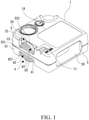
FIG. 1 is a perspective view showing the assembly of an air inflator device according to a first embodiment of the present invention. -
FIG. 2 is a perspective view showing the assembly of a part of the air inflator device according to the first embodiment of the present invention. -
FIG. 3 is a cross sectional view showing the assembly of the air inflator device according to the first embodiment of the present invention. -
FIG. 4 is a side plan view showing the operation of the air inflator device according to the first embodiment of the present invention. -
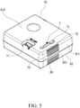
FIG. 5 is a perspective view showing the assembly of an air inflator device according to a second embodiment of the present invention. -
FIG. 6 is a perspective view showing the assembly of a part of the air inflator device according to the second embodiment of the present invention. -
FIG. 7 is a cross sectional view showing the assembly of the air inflator device according to the second embodiment of the present invention. -
FIG. 8 is a side plan view showing the operation of the air inflator device according to the second embodiment of the present invention. - With reference to
FIGS. 1-4 , an air inflator device according to a first embodiment of the present invention comprises: an accommodation box and anair compressor 9, the accommodation box includes acap 1 and acase 2, and theair compressor 9 is received in thecap 1 and thecase 2. Furthermore, an air guiding mechanism is also received in the accommodation box and is configured to frame acooling fan 91 which is rotatably with amotor 92 of theair compressor 9. The air guiding mechanism is configured to collect and guide airs so that thecooling fan 91 rotates to guide the airs to theair compressor 9 quickly, thus dissipating heat and prolonging a service life of theair compressor 9. - Referring to
FIGS. 1 and2 , thecap 1 is formed in a rectangular frame shape and includes afirst panel 10 formed on a top of thecap 1, abutton 11 located beside thefirst panel 10 and configured to turn on/off theair compressor 9, a fluid guide structure which has afirst directing portion 3, and thefirst directing portion 3 has afirst recess 31 defined on a side of a firstperipheral fringe 12 of thecap 1, and a firstsemicircular cover 32 extending on thefirst recess 31, wherein the firstsemicircular cover 32 has afirst rib 321 and a firstarcuate fence 322. Thecap 1 further includes multiple firstelongated orifices 33 separately formed on the firstarcuate fence 322, and the firstsemicircular cover 32 is integrally formed with thecap 1. - Referring to
FIGS. 1 and2 , thecase 2 is formed in a rectangular frame shape and includes a fluid guide structure has asecond directing portion 4 the same as thefirst directing portion 3. Thesecond directing portion 4 has asecond recess 41 defined on a side of a secondperipheral fringe 21 of thecase 2 below asecond panel 20 of a top of thecase 2, and a secondsemicircular cover 42 extending on thesecond recess 41, wherein the secondsemicircular cover 42 has asecond rib 421 and a secondarcuate fence 422. Thecap 1 further includes multiple firstelongated orifices 43 separately formed on the firstarcuate fence 422, and the secondsemicircular cover 42 is integrally formed with thecase 2. - As shown in
FIG. 3 , after theair compressor 9 is received in thecap 1 and thecase 2, thefirst directing portion 3 of thecap 1 and thesecond directing portion 4 of thecase 2 frame thecooling fan 91, and thecooling fan 91 is rotatably with themotor 92 of theair compressor 9, thus avoiding a strike of thecooling fan 91. Furthermore, a flowingorifice 5 is defined by thefirst directing portion 3 and thesecond directing portion 4. As illustrated inFIG. 4 , theair compressor 9 is received in the accommodation box and is dissipated heat. When thecooling fan 91 rotates to guide external airs to flow out of the flowingorifice 5 from the multiple firstelongated orifices 33 and the multiple secondelongated orifice 43 via thefirst directing portion 3 and the second directing portion 4 (as shown inFIG. 3 ), thus collecting and guiding the external airs smoothly. - With reference to
FIG. 4 , theair compressor 9 is received in the accommodation box, thecooling fan 91 is opposite to the accommodation box, wherein a first datum line A is defined between the firstperipheral fringe 12 and the secondperipheral fringe 21, a back line of thecooling fan 91 located in an air flowing zone is defined as a second datum line B, wherein the multiple firstelongated orifices 33 and the multiple secondelongated orifices 43 are located in an area between the first datum line A and the second datum line B. When thecooling fan 91 rotates, the external airs are drawn into the accommodation box from the multiple firstelongated orifices 33 and the multiple secondelongated orifices 43. In this embodiment, the multiple firstelongated orifices 33 and the multiple secondelongated orifices 43 are located on thefirst rib 321 and thesecond rib 421 in the area between the first datum line A and the second datum line B. Alternatively, the multiple firstelongated orifices 33 and the multiple secondelongated orifices 43 are defined on other portions of the accommodation box when a front end of thecooling fan 91 is defined in the area between the first datum line A and the second datum line B. - The
first panel 10 of thecap 1 has afirst fixing extension 34 extending on an inner wall thereof and configured to guide the airs and to fix themotor 92 of theair compressor 9, and thesecond panel 20 of thecase 2 has asecond fixing extension 44 extending on an inner wall thereof and configured to guide the airs and to fix themotor 92 of theair compressor 9. Thefirst fixing extension 34 has atilted face 341 formed on a center thereof, a first tiltedfence 342 extending from a first end of thetilted face 341 to the firstperipheral fringe 12, a second tiltedfence 343 extending from a second end of thetilted face 341 to the firstperipheral fringe 12, as shown inFIG. 4 , wherein thetilted face 341, the first tiltedfence 342, and the second tiltedfence 343 guide the airs forward smoothly. Since a structure of thesecond fixing extension 44 is identical to that of thefirst fixing extension 34, the structure of thesecond fixing extension 44 is not shown. - The
first panel 10 of thecap 1 has a firstarcuate sheet 35 extending from an inner wall thereof, and thesecond panel 20 of thecase 2 has a secondarcuate sheet 36 extending from an inner wall thereof and corresponding to thefirst arcuate sheet 35, wherein a third arcuate sheet of the case is not shown. - The
first fixing extension 34 of thecap 1 and thesecond fixing extension 44 of thecase 2 abut against afirst vent 92a of themotor 92 so that thetilted face 341 of thefirst fixing extension 34 and thesecond fixing extension 44 guide the airs to thefirst vent 92a of themotor 92 directly, thefirst arcuate sheet 35 and thesecond arcuate sheet 36 guide the airs to asecond vent 92b, and the airs flow into themotor 92 from thefirst vent 92a and the second 92b, hence a heat resulting from a friction of a carbon brush and a commutator of themotor 92 and electric currents of armature winding are dissipated. - With reference to
FIGS. 5-8 , an air inflator device according to a second embodiment of the present invention comprises: afirst recess 71 of afirst directing portion 7 defined on afirst panel 610 of acap 61, and a firstsemicircular cover 72 integrally formed on thefirst recess 71, wherein the firstsemicircular cover 72 is arcuate, and thecap 1 further includes multiple firstelongated orifices 73 separately formed on a side of a firstperipheral fringe 611 of thefirst panel 610, wherein the firstperipheral fringe 611 faces thefirst directing portion 7. - A structure of the
second directing portion 8 is identical to that of thefirst directing portion 7, wherein thesecond directing portion 8 includes asecond recess 81 defined on a second panel 620 of acase 62, and a secondsemicircular cover 82 integrally formed on thesecond recess 81, wherein the secondsemicircular cover 82 is arcuate, and multiple secondelongated orifices 83 are separately formed on a side of a secondperipheral fringe 621 of the second panel 620, wherein the secondperipheral fringe 621 faces thesecond directing portion 8. - The
first panel 610 of thecap 61 has a firstarcuate sheet 63 extending from an inner wall thereof, and the second panel 620 of thecase 62 has a second arcuate sheet 64 extending from an inner wall thereof and corresponding to thefirst arcuate sheet 63, wherein a third arcuate sheet of thecase 62 is not shown. - Accordingly, the air inflator device of the present invention contains the accommodation box and the
air compressor 9 received in the accommodation box, and the air guiding mechanism is also received in the accommodation box and is configured to frame thecooling fan 91 which is rotatably with themotor 92 of theair compressor 9. The air guiding mechanism is configured to collect and guide the airs so that thecooling fan 91 rotates to guide the airs to theair compressor 9, thus dissipating the heat and prolonging the service life of theair compressor 9.
Claims (10)
- An air inflator device comprising: an accommodation box and an air compressor (9), the accommodation box including a cap (1) and a case (2), and the air compressor (9) being received in the cap (1) and the case (2), an air guiding mechanism being also received in the accommodation box and being configured to frame a cooling fan (91) which is rotatably with a motor (92) of the air compressor (9), characterized in that
a flowing orifice (5) is defined by a first directing portion (3) and a second directing portion (4), and a first semicircular cover (32) and a second semicircular cover (42) of the air guiding mechanism are configured to collect and guide airs so that the cooling fan (91) rotates to guide the airs to the air compressor (9) quickly, thus dissipating heat and prolonging a service life of the air compressor (9). - The air inflator device as claimed in claim 1, characterized in that the cap (1) is formed in a rectangular frame shape and includes a first panel (10) formed on a top of the cap (1), a button (11) located beside the first panel (10) and configured to turn on/off the air compressor (9), and a fluid guide structure which has a first directing portion (3).
- The air inflator device as claimed in claim 2, characterized in that the first directing portion (3) has a first recess (31) defined on a side of a first peripheral fringe (12) of the cap (1), and the first semicircular cover (32) extending on the first recess (31), wherein the first semicircular cover (32) has a first rib (321) and a first arcuate fence (322), wherein the cap (1) further includes multiple first elongated orifices (33) separately formed on the first arcuate fence (322), and the first semicircular cover (32) is integrally formed with the cap (1).
- The air inflator device as claimed in claim 3, characterized in that the case (2) is formed in a rectangular frame shape and includes a fluid guide structure has a second directing portion (4) the same as the first directing portion (3), the second directing portion (4) has a second recess (41) defined on a side of a second peripheral fringe (21) of the case (2) below a second panel (20) of a top of the case (2), and a second semicircular cover (42) extending on the second recess (41), wherein the second semicircular cover (42) has a second rib (421) and a second arcuate fence (422); the cap (1) further includes multiple first elongated orifices (43) separately formed on the first arcuate fence (422), and the second semicircular cover (42) is integrally formed with the case (2).
- The air inflator device as claimed in claim 4, characterized in that after the air compressor (9) is received in the cap (1) and the case (2), the first directing portion (3) of the cap (1) and the second directing portion (4) of the case (2) frame the cooling fan (91), and the cooling fan (91) is rotatably with the motor (92) of the air compressor (9), thus avoiding a strike of the cooling fan (91); wherein a flowing orifice (5) is defined by the first directing portion (3) and the second directing portion (4).
- The air inflator device as claimed in claim 5, characterized in that a first datum line (A) is defined between the first peripheral fringe (12) and the second peripheral fringe (210), a back line of the cooling fan (91) located in an air flowing zone is defined as a second datum line (B); wherein the multiple first elongated orifices (33) and the multiple second elongated orifices (43) are located in an area between the first datum line (A) and the second datum line (B); when the cooling fan (91) rotates, the external airs are drawn into the accommodation box from the multiple first elongated orifices (33) and the multiple second elongated orifices (43).
- The air inflator device as claimed in claim 4, characterized in that the first panel (10) of the cap (1) has a first fixing extension (34) extending on an inner wall thereof and configured to guide the airs and to fix the motor (92) of the air compressor (9), and the second panel (20) of the case (2) has a second fixing extension (44) extending on an inner wall thereof and configured to guide the airs and to fix the motor (92) of the air compressor (9); the first fixing extension (34) has a tilted face (341) formed on a center thereof, a first tilted fence (342) extending from a first end of the tilted face (341) to the first peripheral fringe (12), a second tilted fence (343) extending from a second end of the tilted face (341) to the first peripheral fringe (12), wherein the tilted face (341), the first tilted fence (342), and the second tilted fence (343) guide the airs forward smoothly, wherein a structure of the second fixing extension (44) is identical to that of the first fixing extension (34).
- The air inflator device as claimed in claim 7, characterized in that the first panel (10) of the cap (1) has a first arcuate sheet (35) extending from an inner wall thereof, and the second panel (20) of the case (2) has a second arcuate sheet (36) extending from an inner wall thereof and corresponding to the first arcuate sheet (35).
- The air inflator device as claimed in claim 2, characterized in that wherein a first recess (71) of a first directing portion (7) is defined on a first panel (610) of a cap (61), and a first semicircular cover (72) is integrally formed on the first recess (71), wherein the first semicircular cover (72) is arcuate, the cap (1) further includes multiple first elongated orifices (73) separately formed on a side of a first peripheral fringe (611) of the first panel (610), and the first peripheral fringe (611) faces the first directing portion (7).
- The air inflator device as claimed in claim 9, characterized in that the case (2) is formed in a rectangular frame shape and includes a fluid guide structure has the second directing portion (4) the same as the first directing portion (3), wherein a structure of the second directing portion (8) is identical to that of the first directing portion (7), wherein the second directing portion (8) includes a second recess (81) defined on a second panel (620) of a case (62), and a second semicircular cover (82) integrally formed on the second recess (81), wherein the second semicircular cover (82) is arcuate, and multiple second elongated orifices (83) are separately formed on a side of a second peripheral fringe (621) of the second panel (620), wherein the second peripheral fringe (621) faces the second directing portion (8).
Applications Claiming Priority (1)
| Application Number | Priority Date | Filing Date | Title |
|---|---|---|---|
| TW109123963A TWI752554B (en) | 2020-07-15 | 2020-07-15 | Air inflator device |
Publications (2)
| Publication Number | Publication Date |
|---|---|
| EP3940243A1 true EP3940243A1 (en) | 2022-01-19 |
| EP3940243B1 EP3940243B1 (en) | 2024-10-30 |
Family
ID=76942906
Family Applications (1)
| Application Number | Title | Priority Date | Filing Date |
|---|---|---|---|
| EP21185860.0A Active EP3940243B1 (en) | 2020-07-15 | 2021-07-15 | Air inflator device |
Country Status (7)
| Country | Link |
|---|---|
| US (1) | US20220018343A1 (en) |
| EP (1) | EP3940243B1 (en) |
| JP (2) | JP3234151U (en) |
| KR (1) | KR20220009334A (en) |
| CN (2) | CN215927723U (en) |
| DE (1) | DE202021103640U1 (en) |
| TW (1) | TWI752554B (en) |
Families Citing this family (8)
| Publication number | Priority date | Publication date | Assignee | Title |
|---|---|---|---|---|
| TWI752554B (en) * | 2020-07-15 | 2022-01-11 | 周文三 | Air inflator device |
| TWD218617S (en) * | 2021-08-24 | 2022-05-01 | 周文三 | air compressor unit |
| TWD219744S (en) * | 2021-11-10 | 2022-07-01 | 周文三 | air compressor unit |
| CN114962292B (en) * | 2022-05-16 | 2025-11-28 | 湖南省瑞柯电子科技有限公司 | AC/DC air pump core and inflator pump |
| USD1081729S1 (en) * | 2022-12-07 | 2025-07-01 | Illinois Tool Works Inc. | Inflator |
| TWD235674S (en) | 2024-06-03 | 2024-12-21 | 已久工業股份有限公司 臺南市安定區港尾里港子尾1之25號 (中華民國) | Air compressor |
| TWD235675S (en) * | 2024-06-03 | 2024-12-21 | 已久工業股份有限公司 臺南市安定區港尾里港子尾1之25號 (中華民國) | Air compressor |
| CN120697712B (en) * | 2025-07-08 | 2025-12-05 | 珠海市海鹏汽车检测设备有限公司 | Intelligent conjoined valve air flow rate monitoring and inflating system |
Citations (3)
| Publication number | Priority date | Publication date | Assignee | Title |
|---|---|---|---|---|
| DE10127920A1 (en) * | 2000-08-04 | 2002-02-14 | Pari Gmbh | Compressor unit for purifying air has fan-cooled housing with membrane pump to compress incoming air through filter and outlet spigot with limited protrusion from housing |
| JP2005256750A (en) * | 2004-03-12 | 2005-09-22 | Bridgestone Corp | Pump up device |
| DE202015103097U1 (en) * | 2014-06-27 | 2015-10-28 | Wen-San Chou | Portable air compressor |
Family Cites Families (18)
| Publication number | Priority date | Publication date | Assignee | Title |
|---|---|---|---|---|
| US3650639A (en) * | 1970-01-21 | 1972-03-21 | Itt | Air pumps |
| JP3419080B2 (en) * | 1993-07-26 | 2003-06-23 | 株式会社デンソー | Rotating electric machine |
| DE19908308A1 (en) * | 1999-02-26 | 2000-08-31 | Boge Kompressoren | Compressors |
| US6431839B2 (en) * | 2000-07-19 | 2002-08-13 | Campbell Hausfeld/Scott Fetzer Company | Air compressor assembly with shroud |
| US6666660B2 (en) * | 2001-04-27 | 2003-12-23 | The Hoover Company | Motor-fan assembly for a floor cleaning machine |
| CN101119627B (en) * | 2003-06-11 | 2012-07-18 | 台达电子工业股份有限公司 | Heat dissipation device and its fan frame structure |
| NO322287B1 (en) * | 2004-09-24 | 2006-09-11 | Sperre Mek Verksted As | Cooling device for piston machinery |
| US9476416B2 (en) * | 2013-11-22 | 2016-10-25 | Chi-Wen Chen | Air compressor |
| TWM476242U (en) * | 2013-12-17 | 2014-04-11 | Shan Sung Green-Energy Tech Co Ltd | Improvement of circulation fan structure |
| TWI575159B (en) * | 2014-05-26 | 2017-03-21 | 周文三 | Portable pump module |
| TWI593883B (en) * | 2015-01-15 | 2017-08-01 | 周文三 | Inflator having an enhanced cooling effect on a motor thereof |
| TWM519677U (en) * | 2015-03-11 | 2016-04-01 | Wen-San Chou | Inflator device group structure |
| TWI589776B (en) * | 2015-03-11 | 2017-07-01 | 周文三 | Inflator kit |
| TWI563172B (en) * | 2015-03-11 | 2016-12-21 | Wen-San Chou | Inflator having an enhanced cooling effect on a motor thereof |
| TWI582304B (en) * | 2015-10-20 | 2017-05-11 | 周文三 | Motor structure capable of dissipating heat therein |
| CN107269492B (en) * | 2017-06-30 | 2020-08-28 | 东莞瑞柯电子科技股份有限公司 | Alternating current-direct current double-purpose inflator pump |
| AU2018383657C1 (en) * | 2017-12-15 | 2025-01-02 | Zodiac Pool Systems Llc | Inlet shrouds for fans used principally in water-circulation pumps of swimming pools and spas |
| TWI752554B (en) * | 2020-07-15 | 2022-01-11 | 周文三 | Air inflator device |
-
2020
- 2020-07-15 TW TW109123963A patent/TWI752554B/en active
-
2021
- 2021-07-05 KR KR1020210087725A patent/KR20220009334A/en not_active Ceased
- 2021-07-06 DE DE202021103640.0U patent/DE202021103640U1/en active Active
- 2021-07-12 JP JP2021002709U patent/JP3234151U/en active Active
- 2021-07-12 JP JP2021115058A patent/JP7197640B2/en active Active
- 2021-07-14 CN CN202121601517.8U patent/CN215927723U/en active Active
- 2021-07-14 CN CN202110794465.9A patent/CN113944612A/en active Pending
- 2021-07-14 US US17/375,691 patent/US20220018343A1/en not_active Abandoned
- 2021-07-15 EP EP21185860.0A patent/EP3940243B1/en active Active
Patent Citations (3)
| Publication number | Priority date | Publication date | Assignee | Title |
|---|---|---|---|---|
| DE10127920A1 (en) * | 2000-08-04 | 2002-02-14 | Pari Gmbh | Compressor unit for purifying air has fan-cooled housing with membrane pump to compress incoming air through filter and outlet spigot with limited protrusion from housing |
| JP2005256750A (en) * | 2004-03-12 | 2005-09-22 | Bridgestone Corp | Pump up device |
| DE202015103097U1 (en) * | 2014-06-27 | 2015-10-28 | Wen-San Chou | Portable air compressor |
Also Published As
| Publication number | Publication date |
|---|---|
| CN215927723U (en) | 2022-03-01 |
| TW202204768A (en) | 2022-02-01 |
| EP3940243B1 (en) | 2024-10-30 |
| JP2022019620A (en) | 2022-01-27 |
| US20220018343A1 (en) | 2022-01-20 |
| TWI752554B (en) | 2022-01-11 |
| CN113944612A (en) | 2022-01-18 |
| JP3234151U (en) | 2021-09-24 |
| DE202021103640U1 (en) | 2021-08-10 |
| JP7197640B2 (en) | 2022-12-27 |
| KR20220009334A (en) | 2022-01-24 |
Similar Documents
| Publication | Publication Date | Title |
|---|---|---|
| EP3940243A1 (en) | Air inflator device | |
| EP3045725B1 (en) | Inflator having an enhanced cooling effect on a motor thereof | |
| EP3067559B1 (en) | Inflator | |
| US7064462B2 (en) | Power tools with switched reluctance motor | |
| US7166939B2 (en) | Electric hand tool | |
| US7323797B2 (en) | Power tool | |
| EP3067561B1 (en) | Inflator having an enhanced cooling effect on a motor thereof | |
| US20090121579A1 (en) | Curvilinear brush retainer and brushes for an electric motor assembly | |
| CN212977827U (en) | Direct-drive electric angle grinder | |
| JP6646387B2 (en) | Electric motor | |
| CN214900538U (en) | Electric machine | |
| CN217591397U (en) | Electric tool power heat dissipation mechanism and electric saw using same | |
| CN215499729U (en) | Bias device of coating film revolving rack brush structure | |
| CN210669657U (en) | Brushless motor with rotor seal structure | |
| CN219094695U (en) | Angle grinder with brushless motor sealing structure | |
| CN214412522U (en) | A gas-cooled motor | |
| CN218829413U (en) | Mining explosion-proof motor | |
| CN203871989U (en) | Percussion drill | |
| CN222423393U (en) | A high-efficiency energy-saving motor for pump | |
| JP2014128041A (en) | Rotary electric machine for vehicle | |
| JP4575072B2 (en) | Electric tool | |
| CN111697766A (en) | Electric tool and motor thereof |
Legal Events
| Date | Code | Title | Description |
|---|---|---|---|
| PUAI | Public reference made under article 153(3) epc to a published international application that has entered the european phase |
Free format text: ORIGINAL CODE: 0009012 |
|
| STAA | Information on the status of an ep patent application or granted ep patent |
Free format text: STATUS: REQUEST FOR EXAMINATION WAS MADE |
|
| 17P | Request for examination filed |
Effective date: 20211104 |
|
| AK | Designated contracting states |
Kind code of ref document: A1 Designated state(s): AL AT BE BG CH CY CZ DE DK EE ES FI FR GB GR HR HU IE IS IT LI LT LU LV MC MK MT NL NO PL PT RO RS SE SI SK SM TR |
|
| STAA | Information on the status of an ep patent application or granted ep patent |
Free format text: STATUS: EXAMINATION IS IN PROGRESS |
|
| 17Q | First examination report despatched |
Effective date: 20230823 |
|
| GRAP | Despatch of communication of intention to grant a patent |
Free format text: ORIGINAL CODE: EPIDOSNIGR1 |
|
| STAA | Information on the status of an ep patent application or granted ep patent |
Free format text: STATUS: GRANT OF PATENT IS INTENDED |
|
| GRAS | Grant fee paid |
Free format text: ORIGINAL CODE: EPIDOSNIGR3 |
|
| INTG | Intention to grant announced |
Effective date: 20240814 |
|
| GRAA | (expected) grant |
Free format text: ORIGINAL CODE: 0009210 |
|
| STAA | Information on the status of an ep patent application or granted ep patent |
Free format text: STATUS: THE PATENT HAS BEEN GRANTED |
|
| AK | Designated contracting states |
Kind code of ref document: B1 Designated state(s): AL AT BE BG CH CY CZ DE DK EE ES FI FR GB GR HR HU IE IS IT LI LT LU LV MC MK MT NL NO PL PT RO RS SE SI SK SM TR |
|
| REG | Reference to a national code |
Ref country code: GB Ref legal event code: FG4D |
|
| REG | Reference to a national code |
Ref country code: CH Ref legal event code: EP |
|
| REG | Reference to a national code |
Ref country code: IE Ref legal event code: FG4D |
|
| REG | Reference to a national code |
Ref country code: DE Ref legal event code: R096 Ref document number: 602021020895 Country of ref document: DE |
|
| REG | Reference to a national code |
Ref country code: LT Ref legal event code: MG9D |
|
| REG | Reference to a national code |
Ref country code: NL Ref legal event code: MP Effective date: 20241030 |
|
| PG25 | Lapsed in a contracting state [announced via postgrant information from national office to epo] |
Ref country code: IS Free format text: LAPSE BECAUSE OF FAILURE TO SUBMIT A TRANSLATION OF THE DESCRIPTION OR TO PAY THE FEE WITHIN THE PRESCRIBED TIME-LIMIT Effective date: 20250228 Ref country code: PT Free format text: LAPSE BECAUSE OF FAILURE TO SUBMIT A TRANSLATION OF THE DESCRIPTION OR TO PAY THE FEE WITHIN THE PRESCRIBED TIME-LIMIT Effective date: 20250228 Ref country code: HR Free format text: LAPSE BECAUSE OF FAILURE TO SUBMIT A TRANSLATION OF THE DESCRIPTION OR TO PAY THE FEE WITHIN THE PRESCRIBED TIME-LIMIT Effective date: 20241030 |
|
| PG25 | Lapsed in a contracting state [announced via postgrant information from national office to epo] |
Ref country code: FI Free format text: LAPSE BECAUSE OF FAILURE TO SUBMIT A TRANSLATION OF THE DESCRIPTION OR TO PAY THE FEE WITHIN THE PRESCRIBED TIME-LIMIT Effective date: 20241030 Ref country code: NL Free format text: LAPSE BECAUSE OF FAILURE TO SUBMIT A TRANSLATION OF THE DESCRIPTION OR TO PAY THE FEE WITHIN THE PRESCRIBED TIME-LIMIT Effective date: 20241030 |
|
| REG | Reference to a national code |
Ref country code: AT Ref legal event code: MK05 Ref document number: 1737110 Country of ref document: AT Kind code of ref document: T Effective date: 20241030 |
|
| PG25 | Lapsed in a contracting state [announced via postgrant information from national office to epo] |
Ref country code: BG Free format text: LAPSE BECAUSE OF FAILURE TO SUBMIT A TRANSLATION OF THE DESCRIPTION OR TO PAY THE FEE WITHIN THE PRESCRIBED TIME-LIMIT Effective date: 20241030 |
|
| PG25 | Lapsed in a contracting state [announced via postgrant information from national office to epo] |
Ref country code: ES Free format text: LAPSE BECAUSE OF FAILURE TO SUBMIT A TRANSLATION OF THE DESCRIPTION OR TO PAY THE FEE WITHIN THE PRESCRIBED TIME-LIMIT Effective date: 20241030 |
|
| PG25 | Lapsed in a contracting state [announced via postgrant information from national office to epo] |
Ref country code: NO Free format text: LAPSE BECAUSE OF FAILURE TO SUBMIT A TRANSLATION OF THE DESCRIPTION OR TO PAY THE FEE WITHIN THE PRESCRIBED TIME-LIMIT Effective date: 20250130 |
|
| PG25 | Lapsed in a contracting state [announced via postgrant information from national office to epo] |
Ref country code: GR Free format text: LAPSE BECAUSE OF FAILURE TO SUBMIT A TRANSLATION OF THE DESCRIPTION OR TO PAY THE FEE WITHIN THE PRESCRIBED TIME-LIMIT Effective date: 20250131 Ref country code: LV Free format text: LAPSE BECAUSE OF FAILURE TO SUBMIT A TRANSLATION OF THE DESCRIPTION OR TO PAY THE FEE WITHIN THE PRESCRIBED TIME-LIMIT Effective date: 20241030 Ref country code: AT Free format text: LAPSE BECAUSE OF FAILURE TO SUBMIT A TRANSLATION OF THE DESCRIPTION OR TO PAY THE FEE WITHIN THE PRESCRIBED TIME-LIMIT Effective date: 20241030 |
|
| PG25 | Lapsed in a contracting state [announced via postgrant information from national office to epo] |
Ref country code: PL Free format text: LAPSE BECAUSE OF FAILURE TO SUBMIT A TRANSLATION OF THE DESCRIPTION OR TO PAY THE FEE WITHIN THE PRESCRIBED TIME-LIMIT Effective date: 20241030 |
|
| PG25 | Lapsed in a contracting state [announced via postgrant information from national office to epo] |
Ref country code: RS Free format text: LAPSE BECAUSE OF FAILURE TO SUBMIT A TRANSLATION OF THE DESCRIPTION OR TO PAY THE FEE WITHIN THE PRESCRIBED TIME-LIMIT Effective date: 20250130 |
|
| PG25 | Lapsed in a contracting state [announced via postgrant information from national office to epo] |
Ref country code: SM Free format text: LAPSE BECAUSE OF FAILURE TO SUBMIT A TRANSLATION OF THE DESCRIPTION OR TO PAY THE FEE WITHIN THE PRESCRIBED TIME-LIMIT Effective date: 20241030 |
|
| PG25 | Lapsed in a contracting state [announced via postgrant information from national office to epo] |
Ref country code: DK Free format text: LAPSE BECAUSE OF FAILURE TO SUBMIT A TRANSLATION OF THE DESCRIPTION OR TO PAY THE FEE WITHIN THE PRESCRIBED TIME-LIMIT Effective date: 20241030 |
|
| PG25 | Lapsed in a contracting state [announced via postgrant information from national office to epo] |
Ref country code: EE Free format text: LAPSE BECAUSE OF FAILURE TO SUBMIT A TRANSLATION OF THE DESCRIPTION OR TO PAY THE FEE WITHIN THE PRESCRIBED TIME-LIMIT Effective date: 20241030 |
|
| PG25 | Lapsed in a contracting state [announced via postgrant information from national office to epo] |
Ref country code: RO Free format text: LAPSE BECAUSE OF FAILURE TO SUBMIT A TRANSLATION OF THE DESCRIPTION OR TO PAY THE FEE WITHIN THE PRESCRIBED TIME-LIMIT Effective date: 20241030 |
|
| PG25 | Lapsed in a contracting state [announced via postgrant information from national office to epo] |
Ref country code: SK Free format text: LAPSE BECAUSE OF FAILURE TO SUBMIT A TRANSLATION OF THE DESCRIPTION OR TO PAY THE FEE WITHIN THE PRESCRIBED TIME-LIMIT Effective date: 20241030 |
|
| PG25 | Lapsed in a contracting state [announced via postgrant information from national office to epo] |
Ref country code: CZ Free format text: LAPSE BECAUSE OF FAILURE TO SUBMIT A TRANSLATION OF THE DESCRIPTION OR TO PAY THE FEE WITHIN THE PRESCRIBED TIME-LIMIT Effective date: 20241030 |
|
| PG25 | Lapsed in a contracting state [announced via postgrant information from national office to epo] |
Ref country code: IT Free format text: LAPSE BECAUSE OF FAILURE TO SUBMIT A TRANSLATION OF THE DESCRIPTION OR TO PAY THE FEE WITHIN THE PRESCRIBED TIME-LIMIT Effective date: 20241030 |
|
| REG | Reference to a national code |
Ref country code: DE Ref legal event code: R097 Ref document number: 602021020895 Country of ref document: DE |
|
| PLBE | No opposition filed within time limit |
Free format text: ORIGINAL CODE: 0009261 |
|
| STAA | Information on the status of an ep patent application or granted ep patent |
Free format text: STATUS: NO OPPOSITION FILED WITHIN TIME LIMIT |
|
| PG25 | Lapsed in a contracting state [announced via postgrant information from national office to epo] |
Ref country code: SE Free format text: LAPSE BECAUSE OF FAILURE TO SUBMIT A TRANSLATION OF THE DESCRIPTION OR TO PAY THE FEE WITHIN THE PRESCRIBED TIME-LIMIT Effective date: 20241030 |
|
| 26N | No opposition filed |
Effective date: 20250731 |
|
| PGFP | Annual fee paid to national office [announced via postgrant information from national office to epo] |
Ref country code: DE Payment date: 20250702 Year of fee payment: 5 |
|
| REG | Reference to a national code |
Ref country code: CH Ref legal event code: H13 Free format text: ST27 STATUS EVENT CODE: U-0-0-H10-H13 (AS PROVIDED BY THE NATIONAL OFFICE) Effective date: 20260224 |
|
| PG25 | Lapsed in a contracting state [announced via postgrant information from national office to epo] |
Ref country code: LU Free format text: LAPSE BECAUSE OF NON-PAYMENT OF DUE FEES Effective date: 20250715 |
|
| GBPC | Gb: european patent ceased through non-payment of renewal fee |
Effective date: 20250715 |
|
| REG | Reference to a national code |
Ref country code: BE Ref legal event code: MM Effective date: 20250731 |
|
| PG25 | Lapsed in a contracting state [announced via postgrant information from national office to epo] |
Ref country code: GB Free format text: LAPSE BECAUSE OF NON-PAYMENT OF DUE FEES Effective date: 20250715 |
|
| PG25 | Lapsed in a contracting state [announced via postgrant information from national office to epo] |
Ref country code: BE Free format text: LAPSE BECAUSE OF NON-PAYMENT OF DUE FEES Effective date: 20250731 |
|
| PG25 | Lapsed in a contracting state [announced via postgrant information from national office to epo] |
Ref country code: FR Free format text: LAPSE BECAUSE OF NON-PAYMENT OF DUE FEES Effective date: 20250731 |
|
| PG25 | Lapsed in a contracting state [announced via postgrant information from national office to epo] |
Ref country code: CH Free format text: LAPSE BECAUSE OF NON-PAYMENT OF DUE FEES Effective date: 20250731 |