EP3940109A1 - Tungsten oxide sputtering target - Google Patents
Tungsten oxide sputtering target Download PDFInfo
- Publication number
- EP3940109A1 EP3940109A1 EP20774627.2A EP20774627A EP3940109A1 EP 3940109 A1 EP3940109 A1 EP 3940109A1 EP 20774627 A EP20774627 A EP 20774627A EP 3940109 A1 EP3940109 A1 EP 3940109A1
- Authority
- EP
- European Patent Office
- Prior art keywords
- sputtering
- tungsten oxide
- diffraction intensity
- plane
- phase
- Prior art date
- Legal status (The legal status is an assumption and is not a legal conclusion. Google has not performed a legal analysis and makes no representation as to the accuracy of the status listed.)
- Withdrawn
Links
- QGLKJKCYBOYXKC-UHFFFAOYSA-N nonaoxidotritungsten Chemical compound O=[W]1(=O)O[W](=O)(=O)O[W](=O)(=O)O1 QGLKJKCYBOYXKC-UHFFFAOYSA-N 0.000 title claims description 64
- 229910001930 tungsten oxide Inorganic materials 0.000 title claims description 64
- 238000005477 sputtering target Methods 0.000 title claims description 57
- 238000004544 sputter deposition Methods 0.000 claims abstract description 156
- 238000002441 X-ray diffraction Methods 0.000 claims abstract description 13
- 229910052751 metal Inorganic materials 0.000 claims description 35
- 239000002184 metal Substances 0.000 claims description 35
- 239000000654 additive Substances 0.000 claims description 31
- 230000000996 additive effect Effects 0.000 claims description 31
- 239000000203 mixture Substances 0.000 claims description 17
- 229910052782 aluminium Inorganic materials 0.000 claims description 9
- 150000002739 metals Chemical class 0.000 claims description 9
- 229910052758 niobium Inorganic materials 0.000 claims description 9
- 229910052710 silicon Inorganic materials 0.000 claims description 9
- 229910052715 tantalum Inorganic materials 0.000 claims description 9
- 229910052719 titanium Inorganic materials 0.000 claims description 9
- 229910052721 tungsten Inorganic materials 0.000 claims description 9
- 229910052727 yttrium Inorganic materials 0.000 claims description 9
- 229910052726 zirconium Inorganic materials 0.000 claims description 9
- WFKWXMTUELFFGS-UHFFFAOYSA-N tungsten Chemical compound [W] WFKWXMTUELFFGS-UHFFFAOYSA-N 0.000 claims description 7
- 239000010937 tungsten Substances 0.000 claims description 7
- 238000005245 sintering Methods 0.000 description 55
- 239000000843 powder Substances 0.000 description 48
- 238000007731 hot pressing Methods 0.000 description 47
- 230000002159 abnormal effect Effects 0.000 description 30
- 238000000034 method Methods 0.000 description 19
- 238000012360 testing method Methods 0.000 description 18
- 230000000052 comparative effect Effects 0.000 description 12
- 239000002994 raw material Substances 0.000 description 12
- 238000001513 hot isostatic pressing Methods 0.000 description 11
- 239000000523 sample Substances 0.000 description 11
- MCMNRKCIXSYSNV-UHFFFAOYSA-N Zirconium dioxide Chemical compound O=[Zr]=O MCMNRKCIXSYSNV-UHFFFAOYSA-N 0.000 description 10
- 239000003513 alkali Substances 0.000 description 10
- 238000005259 measurement Methods 0.000 description 10
- 239000002245 particle Substances 0.000 description 10
- 230000003628 erosive effect Effects 0.000 description 7
- VYPSYNLAJGMNEJ-UHFFFAOYSA-N Silicium dioxide Chemical compound O=[Si]=O VYPSYNLAJGMNEJ-UHFFFAOYSA-N 0.000 description 6
- 125000004429 atom Chemical group 0.000 description 6
- 238000010438 heat treatment Methods 0.000 description 6
- 238000003754 machining Methods 0.000 description 6
- ZKATWMILCYLAPD-UHFFFAOYSA-N niobium pentoxide Chemical compound O=[Nb](=O)O[Nb](=O)=O ZKATWMILCYLAPD-UHFFFAOYSA-N 0.000 description 6
- 238000002156 mixing Methods 0.000 description 5
- GWEVSGVZZGPLCZ-UHFFFAOYSA-N Titan oxide Chemical compound O=[Ti]=O GWEVSGVZZGPLCZ-UHFFFAOYSA-N 0.000 description 4
- 230000015572 biosynthetic process Effects 0.000 description 4
- 239000013078 crystal Substances 0.000 description 4
- 238000009826 distribution Methods 0.000 description 4
- 238000011156 evaluation Methods 0.000 description 4
- 238000010304 firing Methods 0.000 description 4
- 238000004519 manufacturing process Methods 0.000 description 4
- WGTYBPLFGIVFAS-UHFFFAOYSA-M tetramethylammonium hydroxide Chemical compound [OH-].C[N+](C)(C)C WGTYBPLFGIVFAS-UHFFFAOYSA-M 0.000 description 4
- PNEYBMLMFCGWSK-UHFFFAOYSA-N aluminium oxide Inorganic materials [O-2].[O-2].[O-2].[Al+3].[Al+3] PNEYBMLMFCGWSK-UHFFFAOYSA-N 0.000 description 3
- 229910052681 coesite Inorganic materials 0.000 description 3
- 230000001276 controlling effect Effects 0.000 description 3
- 229910052593 corundum Inorganic materials 0.000 description 3
- 229910052906 cristobalite Inorganic materials 0.000 description 3
- 239000007789 gas Substances 0.000 description 3
- 239000001257 hydrogen Substances 0.000 description 3
- 229910052739 hydrogen Inorganic materials 0.000 description 3
- 238000001755 magnetron sputter deposition Methods 0.000 description 3
- 229910052760 oxygen Inorganic materials 0.000 description 3
- 239000000377 silicon dioxide Substances 0.000 description 3
- 229910052682 stishovite Inorganic materials 0.000 description 3
- PBCFLUZVCVVTBY-UHFFFAOYSA-N tantalum pentoxide Inorganic materials O=[Ta](=O)O[Ta](=O)=O PBCFLUZVCVVTBY-UHFFFAOYSA-N 0.000 description 3
- 229910052905 tridymite Inorganic materials 0.000 description 3
- 229910001845 yogo sapphire Inorganic materials 0.000 description 3
- UFHFLCQGNIYNRP-UHFFFAOYSA-N Hydrogen Chemical compound [H][H] UFHFLCQGNIYNRP-UHFFFAOYSA-N 0.000 description 2
- 238000004458 analytical method Methods 0.000 description 2
- QVGXLLKOCUKJST-UHFFFAOYSA-N atomic oxygen Chemical compound [O] QVGXLLKOCUKJST-UHFFFAOYSA-N 0.000 description 2
- 238000010586 diagram Methods 0.000 description 2
- 230000000694 effects Effects 0.000 description 2
- 239000003822 epoxy resin Substances 0.000 description 2
- 239000004570 mortar (masonry) Substances 0.000 description 2
- 238000000465 moulding Methods 0.000 description 2
- 230000003647 oxidation Effects 0.000 description 2
- 238000007254 oxidation reaction Methods 0.000 description 2
- 239000001301 oxygen Substances 0.000 description 2
- 238000005498 polishing Methods 0.000 description 2
- 229920000647 polyepoxide Polymers 0.000 description 2
- 238000002360 preparation method Methods 0.000 description 2
- 239000000243 solution Substances 0.000 description 2
- MYMOFIZGZYHOMD-UHFFFAOYSA-N Dioxygen Chemical compound O=O MYMOFIZGZYHOMD-UHFFFAOYSA-N 0.000 description 1
- PWHULOQIROXLJO-UHFFFAOYSA-N Manganese Chemical compound [Mn] PWHULOQIROXLJO-UHFFFAOYSA-N 0.000 description 1
- 239000002253 acid Substances 0.000 description 1
- 239000008186 active pharmaceutical agent Substances 0.000 description 1
- 239000007864 aqueous solution Substances 0.000 description 1
- 238000007906 compression Methods 0.000 description 1
- 230000006835 compression Effects 0.000 description 1
- 238000011161 development Methods 0.000 description 1
- 229910001882 dioxygen Inorganic materials 0.000 description 1
- 238000005530 etching Methods 0.000 description 1
- 238000009472 formulation Methods 0.000 description 1
- 239000012634 fragment Substances 0.000 description 1
- 239000011521 glass Substances 0.000 description 1
- 150000002431 hydrogen Chemical class 0.000 description 1
- 229910052748 manganese Inorganic materials 0.000 description 1
- 239000011572 manganese Substances 0.000 description 1
- 150000002697 manganese compounds Chemical class 0.000 description 1
- 238000013507 mapping Methods 0.000 description 1
- 239000011159 matrix material Substances 0.000 description 1
- 238000000059 patterning Methods 0.000 description 1
- 229920002120 photoresistant polymer Polymers 0.000 description 1
- 238000004445 quantitative analysis Methods 0.000 description 1
- 230000001105 regulatory effect Effects 0.000 description 1
- 239000000758 substrate Substances 0.000 description 1
Images


Classifications
-
- C—CHEMISTRY; METALLURGY
- C23—COATING METALLIC MATERIAL; COATING MATERIAL WITH METALLIC MATERIAL; CHEMICAL SURFACE TREATMENT; DIFFUSION TREATMENT OF METALLIC MATERIAL; COATING BY VACUUM EVAPORATION, BY SPUTTERING, BY ION IMPLANTATION OR BY CHEMICAL VAPOUR DEPOSITION, IN GENERAL; INHIBITING CORROSION OF METALLIC MATERIAL OR INCRUSTATION IN GENERAL
- C23C—COATING METALLIC MATERIAL; COATING MATERIAL WITH METALLIC MATERIAL; SURFACE TREATMENT OF METALLIC MATERIAL BY DIFFUSION INTO THE SURFACE, BY CHEMICAL CONVERSION OR SUBSTITUTION; COATING BY VACUUM EVAPORATION, BY SPUTTERING, BY ION IMPLANTATION OR BY CHEMICAL VAPOUR DEPOSITION, IN GENERAL
- C23C14/00—Coating by vacuum evaporation, by sputtering or by ion implantation of the coating forming material
- C23C14/22—Coating by vacuum evaporation, by sputtering or by ion implantation of the coating forming material characterised by the process of coating
- C23C14/34—Sputtering
- C23C14/3407—Cathode assembly for sputtering apparatus, e.g. Target
- C23C14/3414—Metallurgical or chemical aspects of target preparation, e.g. casting, powder metallurgy
-
- C—CHEMISTRY; METALLURGY
- C01—INORGANIC CHEMISTRY
- C01G—COMPOUNDS CONTAINING METALS NOT COVERED BY SUBCLASSES C01D OR C01F
- C01G41/00—Compounds of tungsten
- C01G41/02—Oxides; Hydroxides
-
- C—CHEMISTRY; METALLURGY
- C04—CEMENTS; CONCRETE; ARTIFICIAL STONE; CERAMICS; REFRACTORIES
- C04B—LIME, MAGNESIA; SLAG; CEMENTS; COMPOSITIONS THEREOF, e.g. MORTARS, CONCRETE OR LIKE BUILDING MATERIALS; ARTIFICIAL STONE; CERAMICS; REFRACTORIES; TREATMENT OF NATURAL STONE
- C04B35/00—Shaped ceramic products characterised by their composition; Ceramics compositions; Processing powders of inorganic compounds preparatory to the manufacturing of ceramic products
- C04B35/01—Shaped ceramic products characterised by their composition; Ceramics compositions; Processing powders of inorganic compounds preparatory to the manufacturing of ceramic products based on oxide ceramics
- C04B35/495—Shaped ceramic products characterised by their composition; Ceramics compositions; Processing powders of inorganic compounds preparatory to the manufacturing of ceramic products based on oxide ceramics based on vanadium, niobium, tantalum, molybdenum or tungsten oxides or solid solutions thereof with other oxides, e.g. vanadates, niobates, tantalates, molybdates or tungstates
-
- C—CHEMISTRY; METALLURGY
- C04—CEMENTS; CONCRETE; ARTIFICIAL STONE; CERAMICS; REFRACTORIES
- C04B—LIME, MAGNESIA; SLAG; CEMENTS; COMPOSITIONS THEREOF, e.g. MORTARS, CONCRETE OR LIKE BUILDING MATERIALS; ARTIFICIAL STONE; CERAMICS; REFRACTORIES; TREATMENT OF NATURAL STONE
- C04B35/00—Shaped ceramic products characterised by their composition; Ceramics compositions; Processing powders of inorganic compounds preparatory to the manufacturing of ceramic products
- C04B35/622—Forming processes; Processing powders of inorganic compounds preparatory to the manufacturing of ceramic products
- C04B35/626—Preparing or treating the powders individually or as batches ; preparing or treating macroscopic reinforcing agents for ceramic products, e.g. fibres; mechanical aspects section B
- C04B35/62605—Treating the starting powders individually or as mixtures
- C04B35/62645—Thermal treatment of powders or mixtures thereof other than sintering
- C04B35/6265—Thermal treatment of powders or mixtures thereof other than sintering involving reduction or oxidation
-
- C—CHEMISTRY; METALLURGY
- C04—CEMENTS; CONCRETE; ARTIFICIAL STONE; CERAMICS; REFRACTORIES
- C04B—LIME, MAGNESIA; SLAG; CEMENTS; COMPOSITIONS THEREOF, e.g. MORTARS, CONCRETE OR LIKE BUILDING MATERIALS; ARTIFICIAL STONE; CERAMICS; REFRACTORIES; TREATMENT OF NATURAL STONE
- C04B35/00—Shaped ceramic products characterised by their composition; Ceramics compositions; Processing powders of inorganic compounds preparatory to the manufacturing of ceramic products
- C04B35/622—Forming processes; Processing powders of inorganic compounds preparatory to the manufacturing of ceramic products
- C04B35/64—Burning or sintering processes
- C04B35/645—Pressure sintering
-
- C—CHEMISTRY; METALLURGY
- C04—CEMENTS; CONCRETE; ARTIFICIAL STONE; CERAMICS; REFRACTORIES
- C04B—LIME, MAGNESIA; SLAG; CEMENTS; COMPOSITIONS THEREOF, e.g. MORTARS, CONCRETE OR LIKE BUILDING MATERIALS; ARTIFICIAL STONE; CERAMICS; REFRACTORIES; TREATMENT OF NATURAL STONE
- C04B35/00—Shaped ceramic products characterised by their composition; Ceramics compositions; Processing powders of inorganic compounds preparatory to the manufacturing of ceramic products
- C04B35/622—Forming processes; Processing powders of inorganic compounds preparatory to the manufacturing of ceramic products
- C04B35/64—Burning or sintering processes
- C04B35/645—Pressure sintering
- C04B35/6455—Hot isostatic pressing
-
- C—CHEMISTRY; METALLURGY
- C23—COATING METALLIC MATERIAL; COATING MATERIAL WITH METALLIC MATERIAL; CHEMICAL SURFACE TREATMENT; DIFFUSION TREATMENT OF METALLIC MATERIAL; COATING BY VACUUM EVAPORATION, BY SPUTTERING, BY ION IMPLANTATION OR BY CHEMICAL VAPOUR DEPOSITION, IN GENERAL; INHIBITING CORROSION OF METALLIC MATERIAL OR INCRUSTATION IN GENERAL
- C23C—COATING METALLIC MATERIAL; COATING MATERIAL WITH METALLIC MATERIAL; SURFACE TREATMENT OF METALLIC MATERIAL BY DIFFUSION INTO THE SURFACE, BY CHEMICAL CONVERSION OR SUBSTITUTION; COATING BY VACUUM EVAPORATION, BY SPUTTERING, BY ION IMPLANTATION OR BY CHEMICAL VAPOUR DEPOSITION, IN GENERAL
- C23C14/00—Coating by vacuum evaporation, by sputtering or by ion implantation of the coating forming material
- C23C14/06—Coating by vacuum evaporation, by sputtering or by ion implantation of the coating forming material characterised by the coating material
- C23C14/08—Oxides
- C23C14/083—Oxides of refractory metals or yttrium
-
- H—ELECTRICITY
- H01—ELECTRIC ELEMENTS
- H01J—ELECTRIC DISCHARGE TUBES OR DISCHARGE LAMPS
- H01J37/00—Discharge tubes with provision for introducing objects or material to be exposed to the discharge, e.g. for the purpose of examination or processing thereof
- H01J37/32—Gas-filled discharge tubes
- H01J37/34—Gas-filled discharge tubes operating with cathodic sputtering
- H01J37/3411—Constructional aspects of the reactor
- H01J37/3414—Targets
- H01J37/3426—Material
-
- H—ELECTRICITY
- H01—ELECTRIC ELEMENTS
- H01J—ELECTRIC DISCHARGE TUBES OR DISCHARGE LAMPS
- H01J37/00—Discharge tubes with provision for introducing objects or material to be exposed to the discharge, e.g. for the purpose of examination or processing thereof
- H01J37/32—Gas-filled discharge tubes
- H01J37/34—Gas-filled discharge tubes operating with cathodic sputtering
- H01J37/3411—Constructional aspects of the reactor
- H01J37/3414—Targets
- H01J37/3426—Material
- H01J37/3429—Plural materials
-
- C—CHEMISTRY; METALLURGY
- C01—INORGANIC CHEMISTRY
- C01P—INDEXING SCHEME RELATING TO STRUCTURAL AND PHYSICAL ASPECTS OF SOLID INORGANIC COMPOUNDS
- C01P2002/00—Crystal-structural characteristics
- C01P2002/50—Solid solutions
- C01P2002/52—Solid solutions containing elements as dopants
-
- C—CHEMISTRY; METALLURGY
- C01—INORGANIC CHEMISTRY
- C01P—INDEXING SCHEME RELATING TO STRUCTURAL AND PHYSICAL ASPECTS OF SOLID INORGANIC COMPOUNDS
- C01P2002/00—Crystal-structural characteristics
- C01P2002/70—Crystal-structural characteristics defined by measured X-ray, neutron or electron diffraction data
- C01P2002/72—Crystal-structural characteristics defined by measured X-ray, neutron or electron diffraction data by d-values or two theta-values, e.g. as X-ray diagram
-
- C—CHEMISTRY; METALLURGY
- C01—INORGANIC CHEMISTRY
- C01P—INDEXING SCHEME RELATING TO STRUCTURAL AND PHYSICAL ASPECTS OF SOLID INORGANIC COMPOUNDS
- C01P2002/00—Crystal-structural characteristics
- C01P2002/70—Crystal-structural characteristics defined by measured X-ray, neutron or electron diffraction data
- C01P2002/74—Crystal-structural characteristics defined by measured X-ray, neutron or electron diffraction data by peak-intensities or a ratio thereof only
-
- C—CHEMISTRY; METALLURGY
- C01—INORGANIC CHEMISTRY
- C01P—INDEXING SCHEME RELATING TO STRUCTURAL AND PHYSICAL ASPECTS OF SOLID INORGANIC COMPOUNDS
- C01P2004/00—Particle morphology
- C01P2004/60—Particles characterised by their size
- C01P2004/61—Micrometer sized, i.e. from 1-100 micrometer
-
- C—CHEMISTRY; METALLURGY
- C04—CEMENTS; CONCRETE; ARTIFICIAL STONE; CERAMICS; REFRACTORIES
- C04B—LIME, MAGNESIA; SLAG; CEMENTS; COMPOSITIONS THEREOF, e.g. MORTARS, CONCRETE OR LIKE BUILDING MATERIALS; ARTIFICIAL STONE; CERAMICS; REFRACTORIES; TREATMENT OF NATURAL STONE
- C04B2235/00—Aspects relating to ceramic starting mixtures or sintered ceramic products
- C04B2235/02—Composition of constituents of the starting material or of secondary phases of the final product
- C04B2235/30—Constituents and secondary phases not being of a fibrous nature
- C04B2235/32—Metal oxides, mixed metal oxides, or oxide-forming salts thereof, e.g. carbonates, nitrates, (oxy)hydroxides, chlorides
- C04B2235/3217—Aluminum oxide or oxide forming salts thereof, e.g. bauxite, alpha-alumina
-
- C—CHEMISTRY; METALLURGY
- C04—CEMENTS; CONCRETE; ARTIFICIAL STONE; CERAMICS; REFRACTORIES
- C04B—LIME, MAGNESIA; SLAG; CEMENTS; COMPOSITIONS THEREOF, e.g. MORTARS, CONCRETE OR LIKE BUILDING MATERIALS; ARTIFICIAL STONE; CERAMICS; REFRACTORIES; TREATMENT OF NATURAL STONE
- C04B2235/00—Aspects relating to ceramic starting mixtures or sintered ceramic products
- C04B2235/02—Composition of constituents of the starting material or of secondary phases of the final product
- C04B2235/30—Constituents and secondary phases not being of a fibrous nature
- C04B2235/32—Metal oxides, mixed metal oxides, or oxide-forming salts thereof, e.g. carbonates, nitrates, (oxy)hydroxides, chlorides
- C04B2235/3224—Rare earth oxide or oxide forming salts thereof, e.g. scandium oxide
- C04B2235/3225—Yttrium oxide or oxide-forming salts thereof
-
- C—CHEMISTRY; METALLURGY
- C04—CEMENTS; CONCRETE; ARTIFICIAL STONE; CERAMICS; REFRACTORIES
- C04B—LIME, MAGNESIA; SLAG; CEMENTS; COMPOSITIONS THEREOF, e.g. MORTARS, CONCRETE OR LIKE BUILDING MATERIALS; ARTIFICIAL STONE; CERAMICS; REFRACTORIES; TREATMENT OF NATURAL STONE
- C04B2235/00—Aspects relating to ceramic starting mixtures or sintered ceramic products
- C04B2235/02—Composition of constituents of the starting material or of secondary phases of the final product
- C04B2235/30—Constituents and secondary phases not being of a fibrous nature
- C04B2235/32—Metal oxides, mixed metal oxides, or oxide-forming salts thereof, e.g. carbonates, nitrates, (oxy)hydroxides, chlorides
- C04B2235/3231—Refractory metal oxides, their mixed metal oxides, or oxide-forming salts thereof
- C04B2235/3232—Titanium oxides or titanates, e.g. rutile or anatase
-
- C—CHEMISTRY; METALLURGY
- C04—CEMENTS; CONCRETE; ARTIFICIAL STONE; CERAMICS; REFRACTORIES
- C04B—LIME, MAGNESIA; SLAG; CEMENTS; COMPOSITIONS THEREOF, e.g. MORTARS, CONCRETE OR LIKE BUILDING MATERIALS; ARTIFICIAL STONE; CERAMICS; REFRACTORIES; TREATMENT OF NATURAL STONE
- C04B2235/00—Aspects relating to ceramic starting mixtures or sintered ceramic products
- C04B2235/02—Composition of constituents of the starting material or of secondary phases of the final product
- C04B2235/30—Constituents and secondary phases not being of a fibrous nature
- C04B2235/32—Metal oxides, mixed metal oxides, or oxide-forming salts thereof, e.g. carbonates, nitrates, (oxy)hydroxides, chlorides
- C04B2235/3231—Refractory metal oxides, their mixed metal oxides, or oxide-forming salts thereof
- C04B2235/3244—Zirconium oxides, zirconates, hafnium oxides, hafnates, or oxide-forming salts thereof
-
- C—CHEMISTRY; METALLURGY
- C04—CEMENTS; CONCRETE; ARTIFICIAL STONE; CERAMICS; REFRACTORIES
- C04B—LIME, MAGNESIA; SLAG; CEMENTS; COMPOSITIONS THEREOF, e.g. MORTARS, CONCRETE OR LIKE BUILDING MATERIALS; ARTIFICIAL STONE; CERAMICS; REFRACTORIES; TREATMENT OF NATURAL STONE
- C04B2235/00—Aspects relating to ceramic starting mixtures or sintered ceramic products
- C04B2235/02—Composition of constituents of the starting material or of secondary phases of the final product
- C04B2235/30—Constituents and secondary phases not being of a fibrous nature
- C04B2235/32—Metal oxides, mixed metal oxides, or oxide-forming salts thereof, e.g. carbonates, nitrates, (oxy)hydroxides, chlorides
- C04B2235/3231—Refractory metal oxides, their mixed metal oxides, or oxide-forming salts thereof
- C04B2235/3251—Niobium oxides, niobates, tantalum oxides, tantalates, or oxide-forming salts thereof
-
- C—CHEMISTRY; METALLURGY
- C04—CEMENTS; CONCRETE; ARTIFICIAL STONE; CERAMICS; REFRACTORIES
- C04B—LIME, MAGNESIA; SLAG; CEMENTS; COMPOSITIONS THEREOF, e.g. MORTARS, CONCRETE OR LIKE BUILDING MATERIALS; ARTIFICIAL STONE; CERAMICS; REFRACTORIES; TREATMENT OF NATURAL STONE
- C04B2235/00—Aspects relating to ceramic starting mixtures or sintered ceramic products
- C04B2235/02—Composition of constituents of the starting material or of secondary phases of the final product
- C04B2235/30—Constituents and secondary phases not being of a fibrous nature
- C04B2235/32—Metal oxides, mixed metal oxides, or oxide-forming salts thereof, e.g. carbonates, nitrates, (oxy)hydroxides, chlorides
- C04B2235/3231—Refractory metal oxides, their mixed metal oxides, or oxide-forming salts thereof
- C04B2235/3258—Tungsten oxides, tungstates, or oxide-forming salts thereof
-
- C—CHEMISTRY; METALLURGY
- C04—CEMENTS; CONCRETE; ARTIFICIAL STONE; CERAMICS; REFRACTORIES
- C04B—LIME, MAGNESIA; SLAG; CEMENTS; COMPOSITIONS THEREOF, e.g. MORTARS, CONCRETE OR LIKE BUILDING MATERIALS; ARTIFICIAL STONE; CERAMICS; REFRACTORIES; TREATMENT OF NATURAL STONE
- C04B2235/00—Aspects relating to ceramic starting mixtures or sintered ceramic products
- C04B2235/02—Composition of constituents of the starting material or of secondary phases of the final product
- C04B2235/30—Constituents and secondary phases not being of a fibrous nature
- C04B2235/34—Non-metal oxides, non-metal mixed oxides, or salts thereof that form the non-metal oxides upon heating, e.g. carbonates, nitrates, (oxy)hydroxides, chlorides
- C04B2235/3418—Silicon oxide, silicic acids or oxide forming salts thereof, e.g. silica sol, fused silica, silica fume, cristobalite, quartz or flint
-
- C—CHEMISTRY; METALLURGY
- C04—CEMENTS; CONCRETE; ARTIFICIAL STONE; CERAMICS; REFRACTORIES
- C04B—LIME, MAGNESIA; SLAG; CEMENTS; COMPOSITIONS THEREOF, e.g. MORTARS, CONCRETE OR LIKE BUILDING MATERIALS; ARTIFICIAL STONE; CERAMICS; REFRACTORIES; TREATMENT OF NATURAL STONE
- C04B2235/00—Aspects relating to ceramic starting mixtures or sintered ceramic products
- C04B2235/02—Composition of constituents of the starting material or of secondary phases of the final product
- C04B2235/50—Constituents or additives of the starting mixture chosen for their shape or used because of their shape or their physical appearance
- C04B2235/54—Particle size related information
- C04B2235/5418—Particle size related information expressed by the size of the particles or aggregates thereof
- C04B2235/5436—Particle size related information expressed by the size of the particles or aggregates thereof micrometer sized, i.e. from 1 to 100 micron
-
- C—CHEMISTRY; METALLURGY
- C04—CEMENTS; CONCRETE; ARTIFICIAL STONE; CERAMICS; REFRACTORIES
- C04B—LIME, MAGNESIA; SLAG; CEMENTS; COMPOSITIONS THEREOF, e.g. MORTARS, CONCRETE OR LIKE BUILDING MATERIALS; ARTIFICIAL STONE; CERAMICS; REFRACTORIES; TREATMENT OF NATURAL STONE
- C04B2235/00—Aspects relating to ceramic starting mixtures or sintered ceramic products
- C04B2235/02—Composition of constituents of the starting material or of secondary phases of the final product
- C04B2235/50—Constituents or additives of the starting mixture chosen for their shape or used because of their shape or their physical appearance
- C04B2235/54—Particle size related information
- C04B2235/5418—Particle size related information expressed by the size of the particles or aggregates thereof
- C04B2235/5445—Particle size related information expressed by the size of the particles or aggregates thereof submicron sized, i.e. from 0,1 to 1 micron
-
- C—CHEMISTRY; METALLURGY
- C04—CEMENTS; CONCRETE; ARTIFICIAL STONE; CERAMICS; REFRACTORIES
- C04B—LIME, MAGNESIA; SLAG; CEMENTS; COMPOSITIONS THEREOF, e.g. MORTARS, CONCRETE OR LIKE BUILDING MATERIALS; ARTIFICIAL STONE; CERAMICS; REFRACTORIES; TREATMENT OF NATURAL STONE
- C04B2235/00—Aspects relating to ceramic starting mixtures or sintered ceramic products
- C04B2235/65—Aspects relating to heat treatments of ceramic bodies such as green ceramics or pre-sintered ceramics, e.g. burning, sintering or melting processes
- C04B2235/656—Aspects relating to heat treatments of ceramic bodies such as green ceramics or pre-sintered ceramics, e.g. burning, sintering or melting processes characterised by specific heating conditions during heat treatment
- C04B2235/6562—Heating rate
-
- C—CHEMISTRY; METALLURGY
- C04—CEMENTS; CONCRETE; ARTIFICIAL STONE; CERAMICS; REFRACTORIES
- C04B—LIME, MAGNESIA; SLAG; CEMENTS; COMPOSITIONS THEREOF, e.g. MORTARS, CONCRETE OR LIKE BUILDING MATERIALS; ARTIFICIAL STONE; CERAMICS; REFRACTORIES; TREATMENT OF NATURAL STONE
- C04B2235/00—Aspects relating to ceramic starting mixtures or sintered ceramic products
- C04B2235/65—Aspects relating to heat treatments of ceramic bodies such as green ceramics or pre-sintered ceramics, e.g. burning, sintering or melting processes
- C04B2235/66—Specific sintering techniques, e.g. centrifugal sintering
- C04B2235/661—Multi-step sintering
-
- C—CHEMISTRY; METALLURGY
- C04—CEMENTS; CONCRETE; ARTIFICIAL STONE; CERAMICS; REFRACTORIES
- C04B—LIME, MAGNESIA; SLAG; CEMENTS; COMPOSITIONS THEREOF, e.g. MORTARS, CONCRETE OR LIKE BUILDING MATERIALS; ARTIFICIAL STONE; CERAMICS; REFRACTORIES; TREATMENT OF NATURAL STONE
- C04B2235/00—Aspects relating to ceramic starting mixtures or sintered ceramic products
- C04B2235/65—Aspects relating to heat treatments of ceramic bodies such as green ceramics or pre-sintered ceramics, e.g. burning, sintering or melting processes
- C04B2235/66—Specific sintering techniques, e.g. centrifugal sintering
- C04B2235/668—Pressureless sintering
-
- C—CHEMISTRY; METALLURGY
- C04—CEMENTS; CONCRETE; ARTIFICIAL STONE; CERAMICS; REFRACTORIES
- C04B—LIME, MAGNESIA; SLAG; CEMENTS; COMPOSITIONS THEREOF, e.g. MORTARS, CONCRETE OR LIKE BUILDING MATERIALS; ARTIFICIAL STONE; CERAMICS; REFRACTORIES; TREATMENT OF NATURAL STONE
- C04B2235/00—Aspects relating to ceramic starting mixtures or sintered ceramic products
- C04B2235/70—Aspects relating to sintered or melt-casted ceramic products
- C04B2235/74—Physical characteristics
- C04B2235/77—Density
-
- C—CHEMISTRY; METALLURGY
- C04—CEMENTS; CONCRETE; ARTIFICIAL STONE; CERAMICS; REFRACTORIES
- C04B—LIME, MAGNESIA; SLAG; CEMENTS; COMPOSITIONS THEREOF, e.g. MORTARS, CONCRETE OR LIKE BUILDING MATERIALS; ARTIFICIAL STONE; CERAMICS; REFRACTORIES; TREATMENT OF NATURAL STONE
- C04B2235/00—Aspects relating to ceramic starting mixtures or sintered ceramic products
- C04B2235/70—Aspects relating to sintered or melt-casted ceramic products
- C04B2235/74—Physical characteristics
- C04B2235/79—Non-stoichiometric products, e.g. perovskites (ABO3) with an A/B-ratio other than 1
-
- C—CHEMISTRY; METALLURGY
- C04—CEMENTS; CONCRETE; ARTIFICIAL STONE; CERAMICS; REFRACTORIES
- C04B—LIME, MAGNESIA; SLAG; CEMENTS; COMPOSITIONS THEREOF, e.g. MORTARS, CONCRETE OR LIKE BUILDING MATERIALS; ARTIFICIAL STONE; CERAMICS; REFRACTORIES; TREATMENT OF NATURAL STONE
- C04B2235/00—Aspects relating to ceramic starting mixtures or sintered ceramic products
- C04B2235/70—Aspects relating to sintered or melt-casted ceramic products
- C04B2235/80—Phases present in the sintered or melt-cast ceramic products other than the main phase
-
- C—CHEMISTRY; METALLURGY
- C04—CEMENTS; CONCRETE; ARTIFICIAL STONE; CERAMICS; REFRACTORIES
- C04B—LIME, MAGNESIA; SLAG; CEMENTS; COMPOSITIONS THEREOF, e.g. MORTARS, CONCRETE OR LIKE BUILDING MATERIALS; ARTIFICIAL STONE; CERAMICS; REFRACTORIES; TREATMENT OF NATURAL STONE
- C04B2235/00—Aspects relating to ceramic starting mixtures or sintered ceramic products
- C04B2235/70—Aspects relating to sintered or melt-casted ceramic products
- C04B2235/96—Properties of ceramic products, e.g. mechanical properties such as strength, toughness, wear resistance
-
- C—CHEMISTRY; METALLURGY
- C04—CEMENTS; CONCRETE; ARTIFICIAL STONE; CERAMICS; REFRACTORIES
- C04B—LIME, MAGNESIA; SLAG; CEMENTS; COMPOSITIONS THEREOF, e.g. MORTARS, CONCRETE OR LIKE BUILDING MATERIALS; ARTIFICIAL STONE; CERAMICS; REFRACTORIES; TREATMENT OF NATURAL STONE
- C04B2235/00—Aspects relating to ceramic starting mixtures or sintered ceramic products
- C04B2235/70—Aspects relating to sintered or melt-casted ceramic products
- C04B2235/96—Properties of ceramic products, e.g. mechanical properties such as strength, toughness, wear resistance
- C04B2235/9669—Resistance against chemicals, e.g. against molten glass or molten salts
- C04B2235/9692—Acid, alkali or halogen resistance
Definitions
- the present invention relates to a tungsten oxide sputtering target used when forming a tungsten oxide film.
- Patent Document 1 discloses that a tungsten oxide film (WOx film) is used as a positive electrode of an organic EL element.
- the tungsten oxide film described above is formed by a sputtering method using a sputtering target.
- a tungsten oxide sputtering target formed of a sintered body obtained by sintering a tungsten oxide powder is provided.
- Patent Document 2 discloses a tungsten oxide sputtering target to which manganese or a manganese compound is added as a sintering aid in order to improve a density of the sintered body.
- Patent Document 3 discloses a tungsten oxide sputtering target formed of a sintered body sintered in a vacuum by using a tungsten oxide powder containing WO 2 and at least one of W 18 O 49 and WO 3 , the sintered body having a composition formed of two or more phases of a WO 2 phase and a W 18 O 49 phase, in order to enable DC sputtering.
- the tungsten oxide sputtering target described above in a case where the DC sputtering is performed, if the sputtering proceeds and a depth of an erosion portion becomes deep, abnormal discharge occurs frequently and it is difficult to stably perform DC sputtering. Accordingly, the tungsten oxide sputtering target cannot be used stably for a long period of time, and there is a problem that the service life is shortened.
- the present invention has been made in view of the above-mentioned circumstances, and an object thereof is to provide a tungsten oxide sputtering target capable of suppressing occurrence of abnormal discharge, although the sputtering proceeds, stably performing sputtering film formation for a long period of time, and extending the service life.
- a tungsten oxide sputtering target of the present invention in which a W 18 O 49 peak is confirmed by X-ray diffraction analysis of a sputtering surface and a cross section orthogonal to the sputtering surface, a ratio I S(103) /I S(010) of a diffraction intensity I S(103) of a (103) plane to a diffraction intensity I S(010) of a (010) plane of W 18 O 49 of the sputtering surface is 0.38 or less, a ratio I C(103) /I C(010) of a diffraction intensity I C(103) of the (103) plane to a diffraction intensity I C(010) of the (010) plane of W 18 O 49 of the cross section is 0.55 or more, and an area ratio of W 18 O 49 phase of a surface parallel to the sputtering surface is 37% or more.
- the W 18 O 49 peak is confirmed by the X-ray diffraction analysis on the sputtering surface and the cross section orthogonal to the sputtering surface, and the area ratio of W 18 O 49 phase of the surface parallel to the sputtering surface is 37% or more. Accordingly, it is possible to ensure conductivity and stably perform DC sputtering. In addition, it is possible to ensure the hardness of the tungsten oxide sputtering target.
- the ratio I S(103) /I S(010) of the diffraction intensity I S(103) of the (103) plane to the diffraction intensity I S(010) of the (010) plane of W 18 O 49 of the sputtering surface is 0.38 or less
- the ratio I C(103) /I C(010) of the diffraction intensity I C(103) of the (103) plane to the diffraction intensity I C(010) of the (010) plane of W 18 O 49 of the cross section is 0.55 or more
- the (103) plane of W 18 O 49 is strongly oriented on the cross section orthogonal to the sputtering surface. Accordingly, although the sputtering proceeds and the erosion portion is formed, it is possible to suppress the occurrence of abnormal discharge and stably perform the DC sputtering for a long period of time. Therefore, it is possible to extend the service life.
- the tungsten oxide sputtering target of the present invention preferably has a composition of WOx (2.1 ⁇ X ⁇ 2.9).
- the composition is WOx (2.1 ⁇ X ⁇ 2.9)
- the presence of a large amount of WO 2 and WO 3 phases is suppressed, and it is possible to sufficiently ensure the W 18 O 49 phase having high conductivity and more stably perform the DC sputtering.
- the tungsten oxide sputtering target of the present invention contains an oxide of any one or two or more additive metals of Nb, Ta, Ti, Zr, Y, Al and Si, and as a metal component, in a case where a total amount of the additive metal is defined as M (mass%) and an amount of tungsten is defined as W (mass%), M/(W + M) is in a range of 0.1 or more and 0.67 or less.
- the oxide of any one or two or more additive metals of Nb, Ta, Ti, Zr, Y, Al and Si is contained, and in a case where a total amount of the additive metal is defined as M (mass%) and an amount of tungsten is defined as W (mass%), M/(W + M) is 0.1 or more. Accordingly, it is possible to improve alkali resistance of the formed oxide film. In addition, since M/(W + M) is 0.67 or less, it is possible to suppress the occurrence of abnormal discharge due to the oxide of the additive metal.
- tungsten oxide sputtering target capable of suppressing occurrence of abnormal discharge, although the sputtering proceeds, stably performing sputtering film formation for a long period of time, and extending the service life.
- the W 18 O 49 peak is confirmed by the X-ray diffraction analysis on the sputtering surface and the cross section orthogonal to the sputtering surface, and the area ratio of the W 18 O 49 phase as a result of the cross section observation of the surface parallel to the sputtering surface is 37% or more.
- the ratio I S(103) /I S(010) of the diffraction intensity I S(103) of the (103) plane to the diffraction intensity I S(010) of the (010) plane of W 18 O 49 of the sputtering surface is 0.38 or less.
- the ratio I C(103) /I C(010) of the diffraction intensity I C(103) of the (103) plane to the diffraction intensity I C(010) of the (010) plane of W 18 O 49 of the cross section orthogonal to the sputtering surface is 0.55 or more.
- the tungsten oxide sputtering target of the present embodiment preferably has a composition of WO X (2.1 ⁇ X ⁇ 2.9).
- the tungsten oxide sputtering target of the present embodiment contains an oxide of any one or two or more additive metals of Nb, Ta, Ti, Zr, Y, Al and Si, and as a metal component, in a case where a total amount of the additive metal is defined as M (atom%) and an amount of tungsten is defined as W (atom%), M/(W + M) is in a range of 0.1 or more and 0.67 or less.
- the ratio I S(103) /I S(010) of the diffraction intensity I S(103) of the (103) plane to the diffraction intensity I S(010) of the (010) plane of W 18 O 49 of the sputtering surface the ratio I C(103) /I C(010) of the diffraction intensity I C(103) of the (103) plane to the diffraction intensity I C(010) of the (010) plane of W 18 O 49 of the cross section orthogonal to the sputtering surface, the area ratio of the W 18 O 49 phase of the surface parallel to the sputtering surface, and the composition, the reasons for defining as described above will be described.
- the ratio I S(103) /I S(010) of the diffraction intensity I S(103) of the (103) plane to the diffraction intensity I S(010) of the (010) plane of W 18 O 49 of the sputtering surface is set as 0.38 or less.
- the ratio I S(103) /I S(010) of the diffraction intensity I S(103) of the (103) plane to the diffraction intensity I S(010) of the (010) plane of W 18 O 49 of the sputtering surface is preferably 0.29 or less and more preferably 0.20 or less.
- a lower limit of I S(103) /I S(010) is not particularly limited, and is preferably 0.14 or more.
- an erosion portion is formed on the sputtering surface.
- the orientation of the (103) plane of W 18 O 49 is high on the cross section orthogonal to the sputtering surface, although the sputtering has proceeded, a state in which the (010) plane is strongly oriented on the sputtering surface is maintained. Accordingly, it is possible to suppress the occurrence of abnormal discharge even after the sputtering has proceeded.
- the ratio I C(103) /I C(010) of the diffraction intensity I C(103) of the (103) plane to the diffraction intensity I C(010) of the (010) plane of W 18 O 49 of the cross section orthogonal to the sputtering surface is set as 0.55 or more.
- the ratio I C(103) /I C(010) of the diffraction intensity I C(103) of the (103) plane to the diffraction intensity I C(010) of the (010) plane of W 18 O 49 of the cross section orthogonal to the sputtering surface is preferably 1.18 or more and more preferably 1.41 or more.
- an upper limit of I C(103) /I C(010) is not particularly limited, and is preferably 2.54 or less.
- the W 18 O 49 phase of tungsten oxide has high conductivity, it is possible to improve the conductivity by ensuring the area ratio of the W 18 O 49 phase and to form a tungsten oxide film stably by the DC sputtering.
- the area ratio of the W 18 O 49 phase on the surface parallel to the sputtering surface is set to 37% or more.
- the area ratio of the W 18 O 49 phase on the surface parallel to the sputtering surface can be calculated from an image obtained by performing EPMA analysis on an observation surface of an observation sample. Even in a case where oxides of these additive metals of any one or two or more of Nb, Ta, Ti, Zr, Y, Al, and Si are contained in addition to tungsten oxide, the area ratio of the W 18 O 49 phase may be 37% or more with respect to the entire surface parallel to the sputtering surface containing the oxides of these additive elements.
- the area ratio of the W 18 O 49 phase on the surface parallel to the sputtering surface is preferably 55% or more and more preferably 85% or more.
- an upper limit of the area ratio of the W 18 O 49 phase on the surface parallel to the sputtering surface is not particularly limited, and is preferably 94% or less.
- tungsten oxide Since various phases such as a WO 2 phase, a WO 3 phase, and a W 18 O 49 phase are mixed in tungsten oxide, a ratio of tungsten and oxygen is defined as WOx.
- the ratio of the WO 2 phase can be suppressed, and the W 18 O 49 phase having excellent conductivity can be sufficiently ensured.
- the ratio of the WO 3 phase can be suppressed, and the W 18 O 49 phase having excellent conductivity can be sufficiently ensured. That is, by setting X to 2.1 or more and 2.9 or less, the W 18 O 49 phase becomes a main phase (matrix), and the conductivity of the sputtering target can be ensured.
- a lower limit of X is preferably 2.4 or more.
- an upper limit of X is preferably 2.82 or less.
- alkali is used as a resist peeling solution during patterning by an etching method.
- the oxide of additive metal of any one or two or more of Nb, Ta, Ti, Zr, Y, Al, and Si in tungsten oxide it is possible to improve the alkali resistance of tungsten oxide. Meanwhile, in a case where an amount of the oxide of the additive metal is extremely great, an abnormal discharge may occur during sputtering due to the oxide of the additive metal.
- M/(W + M) is regulated in a range of 0.1 or more and 0.67 or less.
- a lower limit of M/(W + M) is preferably 0.15 or more and more preferably 0.2 or more.
- an upper limit of M/(W + M) is preferably 0.5 or less and more preferably 0.4 or less.
- the method for manufacturing the tungsten oxide sputtering target according to the present embodiment includes a raw material powder preparation step S01, a sintering step S02 for sintering the raw material powder, and a machining process step S03 of machining the obtained sintered body.
- WOx powder containing the WO 2 powder and the W 18 O 49 powder is obtained.
- This WOx powder may contain a WO 3 powder.
- a purity of WO X powder is 99.9 mass% or more.
- the X of the WOx powder is controlled by adjusting the conditions of the reduction treatment.
- the WO 3 powder is heated in a hydrogen atmosphere for a predetermined time at a predetermined temperature to reduce hydrogen.
- the reduction proceeds in the order of WO 3 to WO 2.9 , WO 2.72 , WO 2 , and W.
- a powder formed of WO 3 , WO 2.9 , WO 2.72 , WO 2 , and W can be appropriately mixed with the powder subjected to the reduction treatment as described above.
- the sampled WOx is weighed, then heat-treated at 800°C for 1 hour in the atmosphere, and the weight is measured after the heat treatment. Then, it is confirmed that all of them are WO 3 by X-ray diffraction analysis, and a W amount is calculated by the following formula. Then, a ratio of oxygen is calculated as the X from the obtained W amount.
- Weight of W Weight after heat treatment ⁇ M W / M WO 3
- W mass % weight of W/weight of WO X before heat treatment ⁇ 100 Mw: Atomic weight of W (183.85), M WO3 : Atomic weight of WO 3 (231.85)
- the raw material powder is obtained by mixing the obtained WOx powder.
- a mixing method for example, a dry ball mill using zirconia balls can be used.
- the mixing method is not limited, and a mixer or a blender, specifically, Henschel, rocking, a recon, or the like can be applied.
- An average particle diameter of the raw material powder is preferably in a range of 1 ⁇ m or more and 30 ⁇ m or less.
- various oxide powders are mixed with the WOx powder described above.
- a mixing method for example, a dry ball mill using zirconia balls can be used.
- the mixing method is not limited, and a mixer or a blender, specifically, Henschel, rocking, a recon, or the like can be applied.
- the oxide powder of the additive metal preferably has a greater particle diameter than that of the WOx powder so as not to disturb the sintering of the WOx powders.
- the raw material powder described above is sintered by pressurizing and heating to obtain a sintered body.
- the sintering was performed in vacuum using a hot press device.
- a sintering temperature in the sintering step S02 is in a range of 850°C or higher and 1,400°C or lower, a holding time at the sintering temperature is in a range of 1 hour or longer and 4 hours or shorter, and a pressurizing pressure is in a range of 10 MPa or more and 35 MPa or less.
- the crystal orientation of the sintered body is controlled by controlling the temperature as follows in the sintering step S02.
- the pressurization is performed at the pressurizing pressure described above, and the temperature is raised at a temperature rise rate in a range of 5°C/min or more and 20°C/min or less. Then, it is held at an intermediate temperature in a range of 586°C or higher and 750°C or less in a range of 1 hour or longer and 2 hours or shorter.
- the sintering is performed by raising the temperature to the sintering temperature described above and holding the temperature.
- the (103) plane of W 18 O 49 is strongly oriented on a pressurizing surface (surface orthogonal to a pressurizing direction), and the (010) plane of W 18 O 49 is strongly oriented on a surface orthogonal to the pressurizing surface (surface along the pressurizing direction).
- a lower limit of the intermediate temperature described above is preferably 600°C or higher, and an upper limit of the intermediate temperature is preferably 700°C or lower.
- the obtained sintered body is machined to have a predetermined dimension.
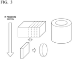
- the machining is performed so that the surface orthogonal to the pressurizing surface is a sputtering surface.
- the sintered body is cut so as to be orthogonal to the pressurizing surface, and the surface orthogonal to the pressurizing surface is used as the sputtering surface.
- a cylindrical surface orthogonal to the pressurizing surface becomes a sputtering surface by pressurizing along an axial direction of a cylinder to obtain a cylindrical sintered body.
- the tungsten oxide sputtering target of the present embodiment is manufactured.
- the W 18 O 49 peak is confirmed by the X-ray diffraction analysis on the sputtering surface and the cross section orthogonal to the sputtering surface, and the area ratio of W 18 O 49 phase is 37% or more. Accordingly, it is possible to ensure conductivity and stably perform DC sputtering. In addition, it is possible to ensure the hardness of the tungsten oxide sputtering target.
- the ratio I S(103) /I S(010) of the diffraction intensity I S(103) of the (103) plane to the diffraction intensity I S(010) of the (010) plane of W 18 O 49 of the sputtering surface is 0.38 or less
- the ratio I C(103) /I C(010) of the diffraction intensity I C(103) of the (103) plane to the diffraction intensity I C(010) of the (010) plane of W 18 O 49 of the cross section orthogonal to the sputtering surface is 0.55 or more
- the (103) plane of W 18 O 49 is strongly oriented on the cross section orthogonal to the sputtering surface.
- the sputtering proceeds and the erosion portion is formed, it is possible to maintain the crystal orientation of the sputtering surface and suppress the occurrence of abnormal discharge. Therefore, it is possible to stably perform the DC sputtering for a long period of time and extend the service life.
- the tungsten oxide sputtering target of the present embodiment in a case where the composition is WOx (2.1 ⁇ X ⁇ 2.9), the presence of a large amount of WO 2 phase or WO 3 phase is suppressed, and it is possible to sufficiently ensure the W 18 O 49 phase and more stably perform the DC sputtering. In addition, it is possible to sufficiently ensure the hardness of the tungsten oxide sputtering target.
- the tungsten oxide sputtering target of the present embodiment contains an oxide of any one or two or more additive metals of Nb, Ta, Ti, Zr, Y, Al and Si, and in a case where a total amount of the additive metal is defined as M (atom%) and an amount of tungsten is defined as W (atom%), M/(W + M) is in a range of 0.1 or less 0.67 and less. In this case, it is possible to improve the alkali resistance of the formed oxide film and suppress the occurrence of abnormal discharge due to the oxide of the additive metal.
- the WOx powder was produced by hydrogen-reduction treatment of the WO 3 powder described above.
- the WOx powders having different x values were prepared by adjusting a degree of reduction.
- An average particle diameter of the raw material powder was 2.4 ⁇ m.
- a Nb 2 O 5 powder (purity: 99.9 mass%, particle diameter D50: 4.6 ⁇ m), a Ta 2 O 5 powder (purity: 99.9 mass%, particle diameter D50: 3.5 ⁇ m), a TiO 2 powder (purity: 99.9 mass%, particle diameter D50: 2.6 ⁇ m), a ZrO 2 powder (purity: 99.9 mass%, particle diameter D50: 11 ⁇ m), a Y 2 O 3 powder (purity: 99.
- a sintering step was carried out with an apparatus (method) and under conditions shown in Tables 1 and 2, to obtain a sintered body.
- Tables 1 and 2 “HP” indicates hot pressing in a vacuum atmosphere, “HIP” indicates a hot isostatic pressing method, and “atmospheric firing” indicates uniaxial molding in an atmospheric atmosphere.
- the temperature was raised at a temperature rise rate of 10°C/min while pressurizing under the pressurizing pressures shown in Tables 1 and 2, and the temperature was held at 600°C (intermediate temperature) for 1 hour. Then, the temperature was raised to the sintering temperature shown in Tables 1 and 2 at a temperature rise rate of 10°C/min, and the temperature was held at the sintering temperature for 2 hours. After that, the pressure was released and the mixture was allowed to cool.
- the temperature was raised at a temperature rise rate of 10°C/min while pressurizing under the pressurizing pressures shown in Tables 1 and 2, and the temperature was held at 700°C (intermediate temperature) for 1 hour. Then, the temperature was raised to the sintering temperature shown in Tables 1 and 2 at a temperature rise rate of 10°C/min, and the temperature was held at the sintering temperature for 2 hours. After that, the pressure was released and the mixture was allowed to cool.
- the temperature was raised to the sintering temperature without holding at the intermediate temperature, and the temperature was held at the sintering temperature for 2 hours. After that, the pressure was released and the mixture was allowed to cool.
- the temperature was raised at a temperature rise rate of 10°C/min while pressurizing under the pressurizing pressures shown in Tables 1 and 2, and the temperature was held at 800°C for 1 hour. Then, the temperature was raised to the sintering temperature shown in Tables 1 and 2 at a temperature rise rate of 10°C/min, and the temperature was held at the sintering temperature for 2 hours. After that, the pressure was released and the mixture was allowed to cool.
- a metal can filled with the raw material powder in a vacuum-sealed state was placed in a pressure vessel of a hot isostatic pressing device that carries out a hot isostatic pressing method, and it is held at the pressure, the sintering temperature shown in Figs. 1 and 2 for 2 hours, and the sintering was performed.
- the obtained sintered body was machined, and a disc-shaped tungsten oxide sputtering target having a diameter of 152.4 mm and a thickness of 6 mm or a cylindrical tungsten oxide sputtering target having a length of 600 mm using four objects having an external diameter of 155 mm, an inner diameter of 135 mm, and a length in an axial direction of 150 mm, was manufactured.
- the machining was performed so that the surface orthogonal to the pressurizing surface became a sputtering surface.
- the obtained tungsten oxide sputtering target was evaluated for the following items.
- a measurement sample was collected so that the sputtering surface and the cross section orthogonal to the sputtering surface are measurement surfaces, and the measurement surfaces were wet-polished with SiC-Paper (grit180).
- the X-ray diffraction analysis was performed under the following conditions by using RINT-ULtima/PC manufactured by Rigaku Denki Co., Ltd.
- a surface index of the obtained X-ray diffraction peak was confirmed using a PDF card number: 1-084-1516 (W 18 O 49 ).
- the evaluation results are shown in Tables 3 and 4.
- an observation sample was collected from the obtained tungsten oxide sputtering target, this was embedded in an epoxy resin so that the cross section parallel to the sputtering surface is an observation surface, a polishing treatment was performed, and then, an element distribution image showing composition distribution of the elements was observed by using a field emission type electron probe microanalyzer (EPMA).
- EPMA field emission type electron probe microanalyzer
- five images of an observation field of view of 0.005 mm 2 (magnification: 500 times) were captured, and the area of the W 18 O 49 phase observed in the images was measured. The measurement results are shown in Tables 3 and 4.
- the area ratio of the W 18 O 49 phase can be measured by the following procedures (a) to (e).
- the sputtering was performed continuously for 1 hour using a DC magnetron sputtering apparatus under the conditions of ultimate vacuum degree of 5 ⁇ 10 -5 Pa or less, a sputtering Ar gas pressure of 0.3 Pa, and a sputtering output of DC 300 W.
- the number of times of occurrences of abnormal discharge per hour of sputtering was counted using an arc counter attached to the power supply of the DC magnetron sputtering apparatus.
- the evaluation results are shown in Tables 3 and 4.
- initial stage is a result of a sputtering test after performing the pre-sputtering for 1 hour.
- a “middle stage” is a result of a sputtering test in a state where a depth of the erosion portion reaches 1/2 of a target thickness.
- a “final stage” is a result of a sputtering test in a state where a residual thickness of the target in the erosion portion is 1 mm.
- a 100 nm film was formed on a glass substrate under the conditions of ultimate vacuum degree of 5 ⁇ 10 -5 Pa or less, a sputtering Ar gas pressure of 0.3 Pa, a sputtering output of 300 W, Ar gas of 90 sccm, and oxygen gas of 10 sccm.
- the obtained film was immersed in a 2.38 mass% aqueous solution of tetramethylammonium hydroxide (TMAH), and the time until the film disappeared was measured and shown in Table 3. In a case where it was 60 seconds or longer, it was determined that the product has alkali resistance that can withstand the wiring step (development of the photoresist step).
- TMAH tetramethylammonium hydroxide
- Comparative Example 1 the sintering was performed under the sintering condition C by hot pressing (HP), but the diffraction intensity ratio I S(103 /I S(010) of W 18 O 49 of the sputtering surface was beyond the range of the present invention.
- the number of times of occurrence of abnormal discharge was 267 times at the middle stage and 422 times at the final stage, and DC sputtering could not be performed stably for a long period of time.
- Comparative Example 10 70 mol% of TiO 2 was contained, the area ratio of the W 18 O 49 phase of the surface parallel to the sputtering surface was low as 24%, and abnormal discharge occurred frequently during DC sputtering and the discharge was stopped. Accordingly, the sputtering could not be performed.
- Example 1 to 10 and 13 of the present invention the number of times of occurrence of abnormal discharges was small at the initial, middle, and final stages of the sputtering test, and DC sputtering could be stably performed for a long period of time.
- Example 11 of the present invention the sintering was performed under the sintering condition A by hot pressing (HP), the cylindrical tungsten oxide sputtering target was manufactured, but the diffraction intensity ratio I S(103) /I S(010) of W 18 O 49 of the sputtering surface and the diffraction intensity ratio I C(103) /I C(010) of W 18 O 49 of the cross section orthogonal to the sputtering surface were in the ranges of the present invention, the area ratio of the W 18 O 49 phase of the surface parallel to the sputtering surface was also in the range of the present invention, and the area ratio of the W 18 O 49 phase was also in the range of the present invention.
- the number of times of occurrence of abnormal discharges was small at the initial, middle, and final stages of the sputtering test, and DC sputtering could be stably performed for a long period of time.
- Example 12 of the present invention as a result of the sintering performed under the sintering condition B by hot pressing (HP), the diffraction intensity ratio I S(103) /I S(010) of W 18 O 49 of the sputtering surface and the diffraction intensity ratio I C(103) /I C(010) of W 18 O 49 of the cross section orthogonal to the sputtering surface were in the ranges of the present invention, and the area ratio of the W 18 O 49 phase of the surface parallel to the sputtering surface was also in the range of the present invention. The number of times of occurrence of abnormal discharges was small at the initial, middle, and final stages of the sputtering test, and DC sputtering could be stably performed for a long period of time.
- the oxide of the additive metal was added, but the diffraction intensity ratio I S(103) /I S(010) of W 18 O 49 of the sputtering surface and the diffraction intensity ratio I C(103) /I C(010) of W 18 O 49 of the cross section orthogonal to the sputtering surface were in the range of the present invention and the area ratio of the W 18 O 49 phase was also in the range of the present invention.
- the number of times of occurrence of abnormal discharges was small at the initial, middle, and final stages of the sputtering test, and DC sputtering could be stably performed for a long period of time.
- the alkali resistance was greatly improved, compared to Examples 1 to 13 of the present invention in which the oxide of the additive metal was not added.
- tungsten oxide sputtering target capable of suppressing occurrence of abnormal discharge, although the sputtering proceeds, stably performing sputtering film formation for a long period of time, and extending the service life.
Landscapes
- Chemical & Material Sciences (AREA)
- Engineering & Computer Science (AREA)
- Organic Chemistry (AREA)
- Ceramic Engineering (AREA)
- Materials Engineering (AREA)
- Manufacturing & Machinery (AREA)
- Inorganic Chemistry (AREA)
- Structural Engineering (AREA)
- Metallurgy (AREA)
- Chemical Kinetics & Catalysis (AREA)
- Mechanical Engineering (AREA)
- Physics & Mathematics (AREA)
- Plasma & Fusion (AREA)
- Analytical Chemistry (AREA)
- Thermal Sciences (AREA)
- Physical Vapour Deposition (AREA)
Abstract
Description
- The present invention relates to a tungsten oxide sputtering target used when forming a tungsten oxide film.
- Priority is claimed on
Japanese Patent Application Nos. 2019-048659 2020-039006, filed March 15, 2019 - The tungsten oxide film is used in various fields such as an electrochromic display element and a light-shielding member. In addition, Patent Document 1 discloses that a tungsten oxide film (WOx film) is used as a positive electrode of an organic EL element.
- As described in Patent Document 1, the tungsten oxide film described above is formed by a sputtering method using a sputtering target.
- As a sputtering target for forming a tungsten oxide film, for example, as shown in Patent Documents 2 and 3, a tungsten oxide sputtering target formed of a sintered body obtained by sintering a tungsten oxide powder is provided.
- Patent Document 2 discloses a tungsten oxide sputtering target to which manganese or a manganese compound is added as a sintering aid in order to improve a density of the sintered body.
- In addition, Patent Document 3 discloses a tungsten oxide sputtering target formed of a sintered body sintered in a vacuum by using a tungsten oxide powder containing WO2 and at least one of W18O49 and WO3, the sintered body having a composition formed of two or more phases of a WO2 phase and a W18O49 phase, in order to enable DC sputtering.
-
- [Patent Document 1]
Japanese Unexamined Patent Application, First Publication No. H11-067459 - [Patent Document 2]
Japanese Unexamined Patent Application, First Publication No. H10-259054 - [Patent Document 3]
Japanese Unexamined Patent Application, First Publication No. 2013-076163 - Meanwhile, in the tungsten oxide sputtering target described above, in a case where the DC sputtering is performed, if the sputtering proceeds and a depth of an erosion portion becomes deep, abnormal discharge occurs frequently and it is difficult to stably perform DC sputtering. Accordingly, the tungsten oxide sputtering target cannot be used stably for a long period of time, and there is a problem that the service life is shortened.
- The present invention has been made in view of the above-mentioned circumstances, and an object thereof is to provide a tungsten oxide sputtering target capable of suppressing occurrence of abnormal discharge, although the sputtering proceeds, stably performing sputtering film formation for a long period of time, and extending the service life.
- As a result of intensive studies by the present inventors in order to solve the above problems, the finding was obtained in which, although the sputtering proceeds and the depth of the erosion portion becomes deeper by setting the crystal orientation on the sputtering surface and the crystal orientation on the cross section orthogonal to the sputtering surface in the predetermined range, it is possible to prevent the occurrence of abnormal discharge and stably perform the DC sputtering for a long period of time.
- The present invention has been made based on the above findings, and there is provided a tungsten oxide sputtering target of the present invention, in which a W18O49 peak is confirmed by X-ray diffraction analysis of a sputtering surface and a cross section orthogonal to the sputtering surface, a ratio IS(103)/IS(010) of a diffraction intensity IS(103) of a (103) plane to a diffraction intensity IS(010) of a (010) plane of W18O49 of the sputtering surface is 0.38 or less, a ratio IC(103)/IC(010) of a diffraction intensity IC(103) of the (103) plane to a diffraction intensity IC(010) of the (010) plane of W18O49 of the cross section is 0.55 or more, and an area ratio of W18O49 phase of a surface parallel to the sputtering surface is 37% or more.
- According to the tungsten oxide sputtering target having this configuration, the W18O49 peak is confirmed by the X-ray diffraction analysis on the sputtering surface and the cross section orthogonal to the sputtering surface, and the area ratio of W18O49 phase of the surface parallel to the sputtering surface is 37% or more. Accordingly, it is possible to ensure conductivity and stably perform DC sputtering. In addition, it is possible to ensure the hardness of the tungsten oxide sputtering target.
- The ratio IS(103)/IS(010) of the diffraction intensity IS(103) of the (103) plane to the diffraction intensity IS(010) of the (010) plane of W18O49 of the sputtering surface is 0.38 or less, the ratio IC(103)/IC(010) of the diffraction intensity IC(103) of the (103) plane to the diffraction intensity IC(010) of the (010) plane of W18O49 of the cross section is 0.55 or more, and the (103) plane of W18O49 is strongly oriented on the cross section orthogonal to the sputtering surface. Accordingly, although the sputtering proceeds and the erosion portion is formed, it is possible to suppress the occurrence of abnormal discharge and stably perform the DC sputtering for a long period of time. Therefore, it is possible to extend the service life.
- The tungsten oxide sputtering target of the present invention preferably has a composition of WOx (2.1 ≤ X ≤ 2.9).
- In this case, since the composition is WOx (2.1 ≤ X ≤ 2.9), the presence of a large amount of WO2 and WO3 phases is suppressed, and it is possible to sufficiently ensure the W18O49 phase having high conductivity and more stably perform the DC sputtering. In addition, it is possible to sufficiently ensure the hardness of the tungsten oxide sputtering target.
- In addition, it is preferable that, the tungsten oxide sputtering target of the present invention contains an oxide of any one or two or more additive metals of Nb, Ta, Ti, Zr, Y, Al and Si, and as a metal component, in a case where a total amount of the additive metal is defined as M (mass%) and an amount of tungsten is defined as W (mass%), M/(W + M) is in a range of 0.1 or more and 0.67 or less.
- In this case, the oxide of any one or two or more additive metals of Nb, Ta, Ti, Zr, Y, Al and Si is contained, and in a case where a total amount of the additive metal is defined as M (mass%) and an amount of tungsten is defined as W (mass%), M/(W + M) is 0.1 or more. Accordingly, it is possible to improve alkali resistance of the formed oxide film. In addition, since M/(W + M) is 0.67 or less, it is possible to suppress the occurrence of abnormal discharge due to the oxide of the additive metal.
- According to the present invention, it is possible to provide a tungsten oxide sputtering target capable of suppressing occurrence of abnormal discharge, although the sputtering proceeds, stably performing sputtering film formation for a long period of time, and extending the service life.
-
-
Fig. 1 is a diagram showing an X-ray diffraction analysis result of a sputtering surface of a tungsten oxide sputtering target and a cross section orthogonal to the sputtering surface according to an embodiment of the present invention. -
Fig. 2 is a flowchart showing a method for manufacturing the tungsten oxide sputtering target according to an embodiment of the present invention. -
Fig. 3 is an explanatory diagram of a machining process step of obtaining a sputtering target from a sintered body in the method for manufacturing the tungsten oxide sputtering target according to an embodiment of the present invention. - Hereinafter, the tungsten oxide sputtering target according to the embodiment of the present invention will be described with reference to the accompanying drawings.
- In the tungsten oxide sputtering target according to the present embodiment, the W18O49 peak is confirmed by the X-ray diffraction analysis on the sputtering surface and the cross section orthogonal to the sputtering surface, and the area ratio of the W18O49 phase as a result of the cross section observation of the surface parallel to the sputtering surface is 37% or more.
- In the tungsten oxide sputtering target according to the present embodiment, as shown in
Fig. 1 , as a result of the X-ray diffraction measurement, the ratio IS(103)/IS(010) of the diffraction intensity IS(103) of the (103) plane to the diffraction intensity IS(010) of the (010) plane of W18O49 of the sputtering surface is 0.38 or less. - In addition, the ratio IC(103)/IC(010) of the diffraction intensity IC(103) of the (103) plane to the diffraction intensity IC(010) of the (010) plane of W18O49 of the cross section orthogonal to the sputtering surface is 0.55 or more.
- The tungsten oxide sputtering target of the present embodiment preferably has a composition of WOX (2.1 ≤ X ≤ 2.9).
- It is preferable that, the tungsten oxide sputtering target of the present embodiment contains an oxide of any one or two or more additive metals of Nb, Ta, Ti, Zr, Y, Al and Si, and as a metal component, in a case where a total amount of the additive metal is defined as M (atom%) and an amount of tungsten is defined as W (atom%), M/(W + M) is in a range of 0.1 or more and 0.67 or less.
- In the tungsten oxide sputtering target according to the present embodiment, regarding the ratio IS(103)/IS(010) of the diffraction intensity IS(103) of the (103) plane to the diffraction intensity IS(010) of the (010) plane of W18O49 of the sputtering surface, the ratio IC(103)/IC(010) of the diffraction intensity IC(103) of the (103) plane to the diffraction intensity IC(010) of the (010) plane of W18O49 of the cross section orthogonal to the sputtering surface, the area ratio of the W18O49 phase of the surface parallel to the sputtering surface, and the composition, the reasons for defining as described above will be described.
- By strongly orienting the (010) plane of W18O49 on the sputtering surface, a sputtering rate is stabilized and the occurrence of abnormal discharge is suppressed.
- Therefore, in the present embodiment, the ratio IS(103)/IS(010) of the diffraction intensity IS(103) of the (103) plane to the diffraction intensity IS(010) of the (010) plane of W18O49 of the sputtering surface is set as 0.38 or less.
- The ratio IS(103)/IS(010) of the diffraction intensity IS(103) of the (103) plane to the diffraction intensity IS(010) of the (010) plane of W18O49 of the sputtering surface is preferably 0.29 or less and more preferably 0.20 or less. In addition, a lower limit of IS(103)/IS(010) is not particularly limited, and is preferably 0.14 or more.
- As the sputtering proceeds, an erosion portion is formed on the sputtering surface. In a case where the orientation of the (103) plane of W18O49 is high on the cross section orthogonal to the sputtering surface, although the sputtering has proceeded, a state in which the (010) plane is strongly oriented on the sputtering surface is maintained. Accordingly, it is possible to suppress the occurrence of abnormal discharge even after the sputtering has proceeded.
- Therefore, in the present embodiment, the ratio IC(103)/IC(010) of the diffraction intensity IC(103) of the (103) plane to the diffraction intensity IC(010) of the (010) plane of W18O49 of the cross section orthogonal to the sputtering surface is set as 0.55 or more.
- The ratio IC(103)/IC(010) of the diffraction intensity IC(103) of the (103) plane to the diffraction intensity IC(010) of the (010) plane of W18O49 of the cross section orthogonal to the sputtering surface is preferably 1.18 or more and more preferably 1.41 or more. In addition, an upper limit of IC(103)/IC(010) is not particularly limited, and is preferably 2.54 or less.
- Since the W18O49 phase of tungsten oxide has high conductivity, it is possible to improve the conductivity by ensuring the area ratio of the W18O49 phase and to form a tungsten oxide film stably by the DC sputtering.
- Therefore, in the present embodiment, the area ratio of the W18O49 phase on the surface parallel to the sputtering surface is set to 37% or more. The area ratio of the W18O49 phase on the surface parallel to the sputtering surface can be calculated from an image obtained by performing EPMA analysis on an observation surface of an observation sample. Even in a case where oxides of these additive metals of any one or two or more of Nb, Ta, Ti, Zr, Y, Al, and Si are contained in addition to tungsten oxide, the area ratio of the W18O49 phase may be 37% or more with respect to the entire surface parallel to the sputtering surface containing the oxides of these additive elements.
- The area ratio of the W18O49 phase on the surface parallel to the sputtering surface is preferably 55% or more and more preferably 85% or more. In addition, an upper limit of the area ratio of the W18O49 phase on the surface parallel to the sputtering surface is not particularly limited, and is preferably 94% or less.
- Since various phases such as a WO2 phase, a WO3 phase, and a W18O49 phase are mixed in tungsten oxide, a ratio of tungsten and oxygen is defined as WOx.
- By setting X to 2.1 or more, the ratio of the WO2 phase can be suppressed, and the W18O49 phase having excellent conductivity can be sufficiently ensured. By setting X to 2.9 or less, the ratio of the WO3 phase can be suppressed, and the W18O49 phase having excellent conductivity can be sufficiently ensured. That is, by setting X to 2.1 or more and 2.9 or less, the W18O49 phase becomes a main phase (matrix), and the conductivity of the sputtering target can be ensured.
- A lower limit of X is preferably 2.4 or more. In addition, an upper limit of X is preferably 2.82 or less.
- In the formed oxide film, alkali is used as a resist peeling solution during patterning by an etching method. By containing the oxide of additive metal of any one or two or more of Nb, Ta, Ti, Zr, Y, Al, and Si in tungsten oxide, it is possible to improve the alkali resistance of tungsten oxide. Meanwhile, in a case where an amount of the oxide of the additive metal is extremely great, an abnormal discharge may occur during sputtering due to the oxide of the additive metal.
- Therefore, in the present embodiment, in a case where an oxide of any one or two or more additive metals of Nb, Ta, Ti, Zr, Y, Al and Si is contained, in a case where a total amount of the additive metal is defined as M (atom%) and an amount of tungsten is defined as W (atom%) as the metal component, M/(W + M) is regulated in a range of 0.1 or more and 0.67 or less.
- A lower limit of M/(W + M) is preferably 0.15 or more and more preferably 0.2 or more. On the other hand, an upper limit of M/(W + M) is preferably 0.5 or less and more preferably 0.4 or less.
- Next, a method for manufacturing the tungsten oxide sputtering target according to the present embodiment will be described with reference to
Figs. 2 and3 . - As shown in
Fig. 2 , the method for manufacturing the tungsten oxide sputtering target according to the present embodiment includes a raw material powder preparation step S01, a sintering step S02 for sintering the raw material powder, and a machining process step S03 of machining the obtained sintered body. - By reducing the WO3 powder, a WOx powder containing the WO2 powder and the W18O49 powder is obtained. This WOx powder may contain a WO3 powder. A purity of WOX powder is 99.9 mass% or more. The X of the WOx powder is controlled by adjusting the conditions of the reduction treatment.
- As the reduction treatment, for example, the WO3 powder is heated in a hydrogen atmosphere for a predetermined time at a predetermined temperature to reduce hydrogen. In this hydrogen reduction, the reduction proceeds in the order of WO3 to WO2.9, WO2.72, WO2, and W. By controlling the proceeding situation of the reduction, it is possible to prepare powders in a mixed state having the composition having different reduction states, and to finely fluctuate an X value of the WOx powder.
- In addition, as a method for controlling and finely adjusting the X value of the WOx powder, a powder formed of WO3, WO2.9, WO2.72, WO2, and W can be appropriately mixed with the powder subjected to the reduction treatment as described above.
- In the quantitation of the X in WOx, the sampled WOx is weighed, then heat-treated at 800°C for 1 hour in the atmosphere, and the weight is measured after the heat treatment. Then, it is confirmed that all of them are WO3 by X-ray diffraction analysis, and a W amount is calculated by the following formula. Then, a ratio of oxygen is calculated as the X from the obtained W amount.


- The raw material powder is obtained by mixing the obtained WOx powder. As a mixing method, for example, a dry ball mill using zirconia balls can be used. The mixing method is not limited, and a mixer or a blender, specifically, Henschel, rocking, a recon, or the like can be applied.
- An average particle diameter of the raw material powder is preferably in a range of 1 µm or more and 30 µm or less.
- In a case where the oxide of additive metals of any one or two or more of Nb, Ta, Ti, Zr, Y, Al, and Si is added, various oxide powders are mixed with the WOx powder described above. As a mixing method, for example, a dry ball mill using zirconia balls can be used. The mixing method is not limited, and a mixer or a blender, specifically, Henschel, rocking, a recon, or the like can be applied.
- In addition, the oxide powder of the additive metal preferably has a greater particle diameter than that of the WOx powder so as not to disturb the sintering of the WOx powders.
- Next, the raw material powder described above is sintered by pressurizing and heating to obtain a sintered body. In the present embodiment, the sintering was performed in vacuum using a hot press device.
- A sintering temperature in the sintering step S02 is in a range of 850°C or higher and 1,400°C or lower, a holding time at the sintering temperature is in a range of 1 hour or longer and 4 hours or shorter, and a pressurizing pressure is in a range of 10 MPa or more and 35 MPa or less.
- In the present embodiment, the crystal orientation of the sintered body is controlled by controlling the temperature as follows in the sintering step S02.
- First, before starting the temperature rise, the pressurization is performed at the pressurizing pressure described above, and the temperature is raised at a temperature rise rate in a range of 5°C/min or more and 20°C/min or less. Then, it is held at an intermediate temperature in a range of 586°C or higher and 750°C or less in a range of 1 hour or longer and 2 hours or shorter. After that, the sintering is performed by raising the temperature to the sintering temperature described above and holding the temperature.
- Accordingly, the (103) plane of W18O49 is strongly oriented on a pressurizing surface (surface orthogonal to a pressurizing direction), and the (010) plane of W18O49 is strongly oriented on a surface orthogonal to the pressurizing surface (surface along the pressurizing direction).
- A lower limit of the intermediate temperature described above is preferably 600°C or higher, and an upper limit of the intermediate temperature is preferably 700°C or lower.
- Next, the obtained sintered body is machined to have a predetermined dimension. At this time, the machining is performed so that the surface orthogonal to the pressurizing surface is a sputtering surface.
- As shown in
Fig. 3 , for example, in a case of a plate-shaped tungsten oxide sputtering target, the sintered body is cut so as to be orthogonal to the pressurizing surface, and the surface orthogonal to the pressurizing surface is used as the sputtering surface. In addition, in a case of a cylindrical tungsten oxide sputtering target, a cylindrical surface orthogonal to the pressurizing surface becomes a sputtering surface by pressurizing along an axial direction of a cylinder to obtain a cylindrical sintered body. - Accordingly, the tungsten oxide sputtering target of the present embodiment is manufactured.
- According to the tungsten oxide sputtering target of the present embodiment having the configuration described above, the W18O49 peak is confirmed by the X-ray diffraction analysis on the sputtering surface and the cross section orthogonal to the sputtering surface, and the area ratio of W18O49 phase is 37% or more. Accordingly, it is possible to ensure conductivity and stably perform DC sputtering. In addition, it is possible to ensure the hardness of the tungsten oxide sputtering target.
- In the tungsten oxide sputtering target of the present embodiment, the ratio IS(103)/IS(010) of the diffraction intensity IS(103) of the (103) plane to the diffraction intensity IS(010) of the (010) plane of W18O49 of the sputtering surface is 0.38 or less, the ratio IC(103)/IC(010) of the diffraction intensity IC(103) of the (103) plane to the diffraction intensity IC(010) of the (010) plane of W18O49 of the cross section orthogonal to the sputtering surface is 0.55 or more, and the (103) plane of W18O49 is strongly oriented on the cross section orthogonal to the sputtering surface. Accordingly, although the sputtering proceeds and the erosion portion is formed, it is possible to maintain the crystal orientation of the sputtering surface and suppress the occurrence of abnormal discharge. Therefore, it is possible to stably perform the DC sputtering for a long period of time and extend the service life.
- Further, in the tungsten oxide sputtering target of the present embodiment, in a case where the composition is WOx (2.1 ≤ X ≤ 2.9), the presence of a large amount of WO2 phase or WO3 phase is suppressed, and it is possible to sufficiently ensure the W18O49 phase and more stably perform the DC sputtering. In addition, it is possible to sufficiently ensure the hardness of the tungsten oxide sputtering target.
- In addition, the tungsten oxide sputtering target of the present embodiment contains an oxide of any one or two or more additive metals of Nb, Ta, Ti, Zr, Y, Al and Si, and in a case where a total amount of the additive metal is defined as M (atom%) and an amount of tungsten is defined as W (atom%), M/(W + M) is in a range of 0.1 or less 0.67 and less. In this case, it is possible to improve the alkali resistance of the formed oxide film and suppress the occurrence of abnormal discharge due to the oxide of the additive metal.
- The embodiments of the present invention have been described as above, but the present invention is not limited thereto, and can be appropriately changed without departing from the technical ideas of the present invention.
- Hereinafter, a result of an evaluation test for evaluating an action effect of the tungsten oxide sputtering target according to the present invention will be described.
- First, the WOx powder was produced by hydrogen-reduction treatment of the WO3 powder described above. In this example, the WOx powders having different x values were prepared by adjusting a degree of reduction. An average particle diameter of the raw material powder was 2.4 µm.
- In addition, as the oxide powders of various additive metals, a Nb2O5 powder (purity: 99.9 mass%, particle diameter D50: 4.6 µm), a Ta2O5 powder (purity: 99.9 mass%, particle diameter D50: 3.5 µm), a TiO2 powder (purity: 99.9 mass%, particle diameter D50: 2.6 µm), a ZrO2 powder (purity: 99.9 mass%, particle diameter D50: 11 µm), a Y2O3 powder (purity: 99. 9 mass%, particle diameter D50: 2.3 µm), an Al2O3 powder (purity: 99.9 mass%, particle diameter D50: 0.2 µm), and a SiO2 powder (purity: 99.9 mass%, particle diameter D50: 1.9 µm) were prepared and mixed with the WOx powder in the formulations shown in Tables 1 and 2.
- Using this raw material powder, a sintering step was carried out with an apparatus (method) and under conditions shown in Tables 1 and 2, to obtain a sintered body. In Tables 1 and 2, "HP" indicates hot pressing in a vacuum atmosphere, "HIP" indicates a hot isostatic pressing method, and "atmospheric firing" indicates uniaxial molding in an atmospheric atmosphere.
- In "HP", the sintering was carried out under the sintering conditions A to D shown below.
- Under the sintering condition A, the temperature was raised at a temperature rise rate of 10°C/min while pressurizing under the pressurizing pressures shown in Tables 1 and 2, and the temperature was held at 600°C (intermediate temperature) for 1 hour. Then, the temperature was raised to the sintering temperature shown in Tables 1 and 2 at a temperature rise rate of 10°C/min, and the temperature was held at the sintering temperature for 2 hours. After that, the pressure was released and the mixture was allowed to cool.
- Under the sintering condition B, the temperature was raised at a temperature rise rate of 10°C/min while pressurizing under the pressurizing pressures shown in Tables 1 and 2, and the temperature was held at 700°C (intermediate temperature) for 1 hour. Then, the temperature was raised to the sintering temperature shown in Tables 1 and 2 at a temperature rise rate of 10°C/min, and the temperature was held at the sintering temperature for 2 hours. After that, the pressure was released and the mixture was allowed to cool.
- Under the sintering condition C, the temperature was raised to the sintering temperature without holding at the intermediate temperature, and the temperature was held at the sintering temperature for 2 hours. After that, the pressure was released and the mixture was allowed to cool.
- Under the sintering condition D, the temperature was raised at a temperature rise rate of 10°C/min while pressurizing under the pressurizing pressures shown in Tables 1 and 2, and the temperature was held at 800°C for 1 hour. Then, the temperature was raised to the sintering temperature shown in Tables 1 and 2 at a temperature rise rate of 10°C/min, and the temperature was held at the sintering temperature for 2 hours. After that, the pressure was released and the mixture was allowed to cool.
- In "HIP", a metal can filled with the raw material powder in a vacuum-sealed state was placed in a pressure vessel of a hot isostatic pressing device that carries out a hot isostatic pressing method, and it is held at the pressure, the sintering temperature shown in
Figs. 1 and2 for 2 hours, and the sintering was performed. - In the "atmospheric firing", a die was filled with raw material powder and compression molded by uniaxial molding to obtain a molded body. This molded body was charged into an atmosphere furnace and held at the sintering temperatures shown in Tables 1 and 2 for 20 hours to perform the sintering.
- The obtained sintered body was machined, and a disc-shaped tungsten oxide sputtering target having a diameter of 152.4 mm and a thickness of 6 mm or a cylindrical tungsten oxide sputtering target having a length of 600 mm using four objects having an external diameter of 155 mm, an inner diameter of 135 mm, and a length in an axial direction of 150 mm, was manufactured. In the sintered body manufactured by the "HP", the machining was performed so that the surface orthogonal to the pressurizing surface became a sputtering surface.
- The obtained tungsten oxide sputtering target was evaluated for the following items.
- A measurement sample was collected from the obtained tungsten oxide sputtering target, this measurement sample was pulverized in a mortar, and X was confirmed by the method for quantifying X of the WOx described above. As a result, it was confirmed that there was no change in X from the blended WOx powder. The evaluation results are shown in Tables 1 and 2.
- Regarding the measurement of the degree of oxidation of Examples 14 to 21 of the present invention to which the oxide of the additive metal is added, first, an observation sample was collected from the obtained tungsten oxide sputtering target, this was embedded in an epoxy resin so that the cross section parallel to the sputtering surface is an observation surface, a polishing treatment was performed, and then, an element distribution image showing composition distribution of the elements was observed by using a field emission type electron probe microanalyzer (EPMA). In addition, in the observation with EPMA, an image of an observation field of view of 0.005 mm2 (magnification: 500 times) was captured. In any five points of a region of the obtained element mapping image of W where W is detected, the quantitative analysis using standard samples of W and O was performed, and an average value of values obtained by measuring the degree of oxidation of W was shown in a column of WOx value of Tables 1 and 2.
- In addition, in Examples 14 to 21 of the present invention in which the oxide of the additive metal was added, fragments of the obtained tungsten oxide sputtering target to which the oxide of the additive metal was added were ground in a Menou mortar, and the powder was dissolved with acid or alkali. After that, the amount of the additive metal was measured by an ICP emission analyzer.
- (X-ray diffraction analysis of sputtering surface and cross section orthogonal to sputtering surface)
- From the obtained tungsten oxide sputtering target, a measurement sample was collected so that the sputtering surface and the cross section orthogonal to the sputtering surface are measurement surfaces, and the measurement surfaces were wet-polished with SiC-Paper (grit180).
- The X-ray diffraction analysis was performed under the following conditions by using RINT-ULtima/PC manufactured by Rigaku Denki Co., Ltd.
- Tube: Cu
- Tube voltage: 40 kV
- Tube current: 50 mA
- Scanning range (2θ): 5° to 80°
- Slit size: divergence (DS) 2/3 degree, scattering (SS) 2/3 degree, light receiving (RS) 0.8 mm
- Measurement step width: 0.02 degrees at 2θ
- Scan speed: 2 degrees per minute
- Sample table rotation speed: 30 rpm
- A surface index of the obtained X-ray diffraction peak was confirmed using a PDF card number: 1-084-1516 (W18O49).
- The ratio IS(103)/IS(010) of the diffraction intensity IS(103) of the (103) plane to the diffraction intensity IS(010) of the (010) plane of W18O49 of the sputtering surface and the ratio IC(103)/IC(010) of the diffraction intensity IC(103) of the (103) plane to the diffraction intensity IC(010) of the (010) plane of W18O49 of the cross section orthogonal to the sputtering surface were calculated. The evaluation results are shown in Tables 3 and 4.
- A density at room temperature was measured from the dimension and weight of the measurement sample. The measurement results are shown in Tables 3 and 4.
- First, an observation sample was collected from the obtained tungsten oxide sputtering target, this was embedded in an epoxy resin so that the cross section parallel to the sputtering surface is an observation surface, a polishing treatment was performed, and then, an element distribution image showing composition distribution of the elements was observed by using a field emission type electron probe microanalyzer (EPMA). In addition, in the observation with EPMA, five images of an observation field of view of 0.005 mm2 (magnification: 500 times) were captured, and the area of the W18O49 phase observed in the images was measured. The measurement results are shown in Tables 3 and 4.
- The area ratio of the W18O49 phase can be measured by the following procedures (a) to (e).
- (a) The generated phase on the observation surface of the observation sample is confirmed by X-ray diffraction analysis under the conditions described above.
- (b) The phase analyzed as W18O49 phase in (a) is identified in the observation field of view by element analysis of EPMA.
- (c) Five images of the observation field of view of COMPO image (60 µm × 80 µm) having a magnification of 500 times were captured by EPMA.
- (d) The W18O49 phase identified in (b) is extracted by commercially available image analysis software, and the captured image is converted into a monochrome image and binarized. As the image analysis software, for example, WinRoof Ver. 5.6.2 (manufactured by Mitani Corporation) and the like can be used.
- (e) From all the binarized images, a total area of all W18O49 phase is calculated and divided by the area of all binarized regions, and the area ratio of the W18O49 phase with respect to the entire observation region is calculated.
- The sputtering was performed continuously for 1 hour using a DC magnetron sputtering apparatus under the conditions of ultimate vacuum degree of 5 × 10⁻⁵ Pa or less, a sputtering Ar gas pressure of 0.3 Pa, and a sputtering output of DC 300 W. At this time, the number of times of occurrences of abnormal discharge per hour of sputtering was counted using an arc counter attached to the power supply of the DC magnetron sputtering apparatus. The evaluation results are shown in Tables 3 and 4.
- In Tables 3 and 4, "initial stage" is a result of a sputtering test after performing the pre-sputtering for 1 hour. A "middle stage" is a result of a sputtering test in a state where a depth of the erosion portion reaches 1/2 of a target thickness. A "final stage" is a result of a sputtering test in a state where a residual thickness of the target in the erosion portion is 1 mm.
- Using the DC magnetron sputtering device, a 100 nm film was formed on a glass substrate under the conditions of ultimate vacuum degree of 5 × 10⁻⁵ Pa or less, a sputtering Ar gas pressure of 0.3 Pa, a sputtering output of 300 W, Ar gas of 90 sccm, and oxygen gas of 10 sccm. The obtained film was immersed in a 2.38 mass% aqueous solution of tetramethylammonium hydroxide (TMAH), and the time until the film disappeared was measured and shown in Table 3. In a case where it was 60 seconds or longer, it was determined that the product has alkali resistance that can withstand the wiring step (development of the photoresist step).
[Table 1] Raw material powder Oxide of additive metal (mol%) Sintering step Sputtering target WOX Value of X Nb2O5 Ta2O5 T1O2 ZrO2 Y2O3 Al2O3 SiO2 Method Sintering condition Sintering temperature °C Pressurizing pressure MPa Shape WOX Value of X M/(W+M) Examples of the present invention 1 2.62 - - - - - - - HP A 1200 20 Plate 2.62 - 2 2.62 - - - - - - - HP A 1200 35 Plate 2.62 - 3 2.62 - - - - - - - HP A 1200 10 Plate 2.62 - 4 2.62 - - - - - - - HP A 1200 8 Plate 2.62 - 5 2.40 - - - - - - - HP A 850 20 Plate 2.40 - 6 2.40 - - - - - - - HP A 900 20 Plate 2.40 - 7 2.40 - - - - - - - HP A 1200 20 Plate 2.40 - 8 2.10 - - - - - - - HP A 1200 35 Plate 2.10 - 9 2.10 - - - - - - - HP A 1200 10 Plate 2.10 - 10 2.82 - - - - - - - HP A 1200 20 Plate 2.82 - 11 2.62 - - - - - - - HP A 1200 20 Cylinder 2.62 - 12 2.62 - - - - - - - HP B 1200 20 Plate 2.62 - 13 2.90 - - - - - - - HP A 900 25 Plate 2.90 - 14 2.90 10 - - - - - - HP A 900 25 Plate 2.89∗ 0.18 15 2.90 25 - - - - - - HP A 900 25 Plate 2.58∗ 0.40 16 2.72 50 - - - - - - HP A 900 25 Plate 2.70∗ 0.67 17 2.90 - 15 - - - - - HP A 1200 35 Plate 2.61∗ 0.26 18 2.72 - - 20 - - - - HP A 1100 35 Plate 2.63∗ 0.15 19 2.90 - - - 10 - - - HP A 1100 35 Plate 2.60∗ 0.10 20 2.90 - - - - 5 - - HP A 1100 35 Plate 2.61∗ 0.11 21 2.90 - - - - - 15 - HP A 1100 35 Plate 2.62∗ 0.26 22 2.90 - - - - - - 15 HP A 1100 35 Plate 2.82∗ 0.14 [Table 2] Raw material powder Oxide of additive metal (mol%) Sintering step Sputtering target WOX Value of X Nb2O5 Ta2O5 T1O2 ZrO2 Y2O3 Al2O3 SiO2 Method Sintering condition Sintering temperature °C Pressurizing pressure MPa Shape WOx Value of X M/(W+M) Comparative example 1 2.62 - - - - - - - HP C 1200 20 Plate 2.62 - 2 2.62 - - - - - - - HIP - 1200 98 Plate 2.62 - 3 2.62 - - - - - - - Atmospheric firing - 1200 - Plate 3.00 - 4 2.40 - - - - - - - HP C 850 20 Plate 2.40 - 5 2.10 - - - - - - - HP C 1200 10 Plate 2.10 - 6 2.06 - - - - - - - HP A 1200 20 Plate 2.06 - 7 2.86 - - - - - - - HP A 1200 20 Plate 2.86 - 8 2.62 - - - - - - - HP D 1200 20 Plate 2.62 - 9 2.62 - - - - - - - HIP - 1200 98 Plate 2.62 - 10 2.90 - - 70 - - - - HP A 1200 25 Plate 2.87∗ 0.70 [Table 3] Area ratio of W18O49 phase % Diffraction intensity ratio IS(103)/IS(010) of W18O49 phase Density g/cm3 Number of times of occurrences of abnormal discharge in sputtering test (time/hour) Alkali resistance of film after atmosphere heat treatment Sputtering surface IS(103)/IS(010) Cross section IC(103)/IC(010) Initial stage Middle stage Final stage Examples of the present invention 1 85 0.17 2.12 8.18 1 3 2 20 2 84 0.14 2.54 8.19 0 1 0 20 3 86 0.36 1.31 8.02 0 3 0 21 4 85 0.37 0.65 8.01 0 1 1 19 5 56 0.32 1.45 6.85 2 1 4 24 6 55 0.29 1.44 7.53 2 1 3 22 7 56 0.31 1.41 8.68 3 3 0 20 8 38 0.29 1.18 9.02 1 1 1 27 9 37 0.38 0.55 8.82 3 2 3 29 10 94 0.18 2.02 7.82 6 4 8 19 11 85 0.23 1.81 8.18 1 3 2 18 12 85 0.20 1.99 8.17 0 1 0 19 13 88 0.30 0.69 6.13 0 0 0 21 14 80 0.35 0.61 4.05 1 0 0 465 15 58 0.38 0.62 3.52 0 1 2 >600 16 37 0.26 0.75 3.33 1 4 3 >600 17 64 0.15 2.28 7.39 4 4 6 >600 18 89 0.22 1.12 6.74 6 5 3 >600 19 92 0.25 1.35 7.03 0 0 0 64 20 84 0.23 1.23 5.76 0 0 1 392 21 74 0.20 1.10 5.57 0 2 1 >600 22 80 0.21 1.13 5.36 1 1 3 >600 [Table 4] Area ratio of W18O49 phase % Diffraction intensity ratio IS(103)/IS(010) of W18O49 phase Density g/cm3 Number of times of occurrences of abnormal discharge in sputtering test (time/hour) Alkali resistance of film after atmosphere heat treatment Sputtering surface IS(103)/IS(010) Cross section IC(103)/IC(010) Initial stage Middle stage Final stage Comparative example 1 86 1.32 1.33 8.19 0 267 422 - 2 85 1.65 1.69 8.20 0 183 378 - 3 0 (No corresponding peak) (No corresponding peak) 6.98 Unable to perform DC sputtering (no conductivity) - 4 54 0.72 0.78 6.81 6 470 1991 - 5 35 0.45 0.50 8.83 1 173 163 - 6 28 0.36 0.88 8.99 258 468 328 - 7 23 0.18 2.02 7.32 Discharge stopped due to great abnormal discharge - 8 85 0.87 1.30 5.57 103 682 1032 - 9 85 1.64 1.62 8.17 0 203 286 - 10 24 0.26 0.75 4.89 Discharge stopped due to great abnormal discharge - - In Comparative Example 1, the sintering was performed under the sintering condition C by hot pressing (HP), but the diffraction intensity ratio IS(103/IS(010) of W18O49 of the sputtering surface was beyond the range of the present invention. In the sputtering test, the number of times of occurrence of abnormal discharge was 267 times at the middle stage and 422 times at the final stage, and DC sputtering could not be performed stably for a long period of time.
- In Comparative Example 2, the sintering was performed by hot isostatic pressing method (HIP), but the diffraction intensity ratio IS(103)/IS(010) of W18O49 of the sputtering surface was beyond the range of the present invention. In the sputtering test, the number of times of occurrence of abnormal discharge was 183 times at the middle stage and 378 times at the final stage, and DC sputtering could not be performed stably for a long period of time.
- In Comparative Example 3, as a result of the atmospheric firing, the W18O49 phase was not confirmed, and DC sputtering could not be performed.
- In Comparative Example 4, the sintering was performed under the sintering condition C by hot pressing (HP), but the diffraction intensity ratio IS(103)/IS(010) of W18O49 of the sputtering surface was beyond the range of the present invention. In the sputtering test, the number of times of occurrence of abnormal discharge was 6 times at the initial stage, 470 times at the middle stage, and 1991 times at the final stage, and DC sputtering could not be performed stably.
- In Comparative Example 5, the sintering was performed under the sintering condition C by hot pressing (HP), but the diffraction intensity ratio IS(103)/IS(010) of W18O49 of the sputtering surface and the diffraction intensity ratio IC(103)/IC(010) of W18O49 of the cross section orthogonal to the sputtering surface were beyond the range of the present invention. In the sputtering test, the number of times of occurrence of abnormal discharge was 173 times at the middle stage and 163 times at the final stage, and DC sputtering could not be performed stably for a long period of time.
- In Comparative Example 6, WOx (X = 2.06) was obtained and the area ratio of the W18O49 phase of the surface parallel to the sputtering surface was low as 28%. In the sputtering test, the number of times of occurrence of abnormal discharge was 258 times at the initial stage, and DC sputtering could not be performed stably. It is surmised that it is because there was a large amount of WO2 phase.
- In Comparative Example 7, WOx (X = 2.86) was obtained, the area ratio of the W18O49 phase of the surface parallel to the sputtering surface was low as 23%, and abnormal discharge occurred frequently during DC sputtering and the discharge was stopped. Accordingly, the sputtering could not be performed. It is surmised that it is because there was a large amount of WO3 phase.
- In Comparative Example 8, the sintering was performed under the sintering condition D by hot pressing (HP), but the density was low and sufficient sintering could not be performed. In addition, the diffraction intensity ratio IS(103)/IS(010) of W18O49 of the sputtering surface was beyond the range of the present invention. In the sputtering test, the number of times of occurrence thereof was 103 times at the initial stage, 682 times at the middle stage, and 1032 times at the final stage, and DC sputtering could not be performed stably.
- In Comparative Example 9, the sintering was performed by hot isostatic pressing method (HIP), but the diffraction intensity ratio IS(103)/IS(010) of W18O49 of the sputtering surface was beyond the range of the present invention. In the sputtering test, the number of times of occurrence thereof was 203 times at the middle stage and 286 times at the final stage, and DC sputtering could not be performed stably.
- In Comparative Example 10, 70 mol% of TiO2 was contained, the area ratio of the W18O49 phase of the surface parallel to the sputtering surface was low as 24%, and abnormal discharge occurred frequently during DC sputtering and the discharge was stopped. Accordingly, the sputtering could not be performed.
- In contrast, in Examples 1 to 10 and 13 of the present invention, as a result of the sintering performed under the sintering condition A by hot pressing (HP), the diffraction intensity ratio IS(103)/IS(010) of W18O49 of the sputtering surface and the diffraction intensity ratio IC(103)/IC(010) of W18O49 of the cross section orthogonal to the sputtering surface were in the ranges of the present invention, and the area ratio of the W18O49 phase of the surface parallel to the sputtering surface was also in the range of the present invention. In Examples 1 to 10 and 13 of the present invention, the number of times of occurrence of abnormal discharges was small at the initial, middle, and final stages of the sputtering test, and DC sputtering could be stably performed for a long period of time.
- In addition, in Example 11 of the present invention, the sintering was performed under the sintering condition A by hot pressing (HP), the cylindrical tungsten oxide sputtering target was manufactured, but the diffraction intensity ratio IS(103)/IS(010) of W18O49 of the sputtering surface and the diffraction intensity ratio IC(103)/IC(010) of W18O49 of the cross section orthogonal to the sputtering surface were in the ranges of the present invention, the area ratio of the W18O49 phase of the surface parallel to the sputtering surface was also in the range of the present invention, and the area ratio of the W18O49 phase was also in the range of the present invention. The number of times of occurrence of abnormal discharges was small at the initial, middle, and final stages of the sputtering test, and DC sputtering could be stably performed for a long period of time.
- In addition, in Example 12 of the present invention, as a result of the sintering performed under the sintering condition B by hot pressing (HP), the diffraction intensity ratio IS(103)/IS(010) of W18O49 of the sputtering surface and the diffraction intensity ratio IC(103)/IC(010) of W18O49 of the cross section orthogonal to the sputtering surface were in the ranges of the present invention, and the area ratio of the W18O49 phase of the surface parallel to the sputtering surface was also in the range of the present invention. The number of times of occurrence of abnormal discharges was small at the initial, middle, and final stages of the sputtering test, and DC sputtering could be stably performed for a long period of time.
- In addition, in Examples 14 to 22 of the present invention, the oxide of the additive metal was added, but the diffraction intensity ratio IS(103)/IS(010) of W18O49 of the sputtering surface and the diffraction intensity ratio IC(103)/IC(010) of W18O49 of the cross section orthogonal to the sputtering surface were in the range of the present invention and the area ratio of the W18O49 phase was also in the range of the present invention. The number of times of occurrence of abnormal discharges was small at the initial, middle, and final stages of the sputtering test, and DC sputtering could be stably performed for a long period of time. The alkali resistance was greatly improved, compared to Examples 1 to 13 of the present invention in which the oxide of the additive metal was not added.
- As described above, according to the present invention, it was confirmed that it is possible to provide a tungsten oxide sputtering target capable of suppressing occurrence of abnormal discharge, although the sputtering proceeds, stably performing sputtering film formation for a long period of time.
- According to the present invention, it is possible to provide a tungsten oxide sputtering target capable of suppressing occurrence of abnormal discharge, although the sputtering proceeds, stably performing sputtering film formation for a long period of time, and extending the service life.
Claims (3)
- A tungsten oxide sputtering target,wherein a W18O49 peak is confirmed by X-ray diffraction analysis of a sputtering surface and a cross section orthogonal to the sputtering surface,a ratio IS(103)/IS(010) of a diffraction intensity IS(103) of a (103) plane to a diffraction intensity IS(010) of a (010) plane of W18O49 of the sputtering surface is 0.38 or less,a ratio IC(103)/IC(010) of a diffraction intensity IC(103) of the (103) plane to a diffraction intensity IC(010) of the (010) plane of W18O49 of the cross section is 0.55 or more, andan area ratio of a W18O49 phase of a surface parallel to the sputtering surface is 37% or more.
- The tungsten oxide sputtering target according to Claim 1 having a composition of WOX (2.1 ≤ X ≤ 2.9).
- The tungsten oxide sputtering target according to Claim 1 or 2, comprising:an oxide of any one or two or more additive metals of Nb, Ta, Ti, Zr, Y, Al and Si,wherein, as a metal component, in a case where a total amount of the additive metal is defined as M (atom%) and an amount of tungsten is defined as W (atom%), M/(W + M) is in a range of 0.1 or more and 0.67 or less.
Applications Claiming Priority (3)
| Application Number | Priority Date | Filing Date | Title |
|---|---|---|---|
| JP2019048659 | 2019-03-15 | ||
| JP2020039006A JP2020153014A (en) | 2019-03-15 | 2020-03-06 | Tungsten oxide sputtering target |
| PCT/JP2020/010423 WO2020189428A1 (en) | 2019-03-15 | 2020-03-11 | Tungsten oxide sputtering target |
Publications (2)
| Publication Number | Publication Date |
|---|---|
| EP3940109A1 true EP3940109A1 (en) | 2022-01-19 |
| EP3940109A4 EP3940109A4 (en) | 2022-11-16 |
Family
ID=72519097
Family Applications (1)
| Application Number | Title | Priority Date | Filing Date |
|---|---|---|---|
| EP20774627.2A Withdrawn EP3940109A4 (en) | 2019-03-15 | 2020-03-11 | Tungsten oxide sputtering target |
Country Status (3)
| Country | Link |
|---|---|
| US (1) | US20220042166A1 (en) |
| EP (1) | EP3940109A4 (en) |
| WO (1) | WO2020189428A1 (en) |
Family Cites Families (9)
| Publication number | Priority date | Publication date | Assignee | Title |
|---|---|---|---|---|
| US4225216A (en) * | 1979-02-21 | 1980-09-30 | Bell Telephone Laboratories, Incorporated | Tungsten niobate electrochromic device |
| JP2693599B2 (en) * | 1989-11-06 | 1997-12-24 | 日本タングステン株式会社 | Target and its manufacturing method |
| JP3731100B2 (en) | 1997-03-14 | 2006-01-05 | 株式会社高純度化学研究所 | Tungsten oxide sintered body, method for producing the same, and powder composition for sintering |
| JPH1167459A (en) | 1997-08-12 | 1999-03-09 | Tdk Corp | Organic EL device and method of manufacturing the same |
| CN101023498B (en) * | 2004-08-31 | 2012-02-29 | 住友金属矿山株式会社 | Conductive particle, visible light transmissive particle dispersed conductor, method for producing same, transparent conductive thin film, method for producing same, transparent conductive article using same, infrared shield article |
| JP5512931B2 (en) | 2007-03-26 | 2014-06-04 | 株式会社半導体エネルギー研究所 | Method for manufacturing semiconductor device |
| JP2013076163A (en) * | 2011-09-15 | 2013-04-25 | Mitsubishi Materials Corp | Sputtering target and method for manufacturing the same |
| JP2019048659A (en) | 2017-09-11 | 2019-03-28 | 日本プラパレット株式会社 | Palette and tag holder |
| WO2020189480A1 (en) * | 2019-03-15 | 2020-09-24 | 三菱マテリアル株式会社 | Tungsten oxide sputtering target |
-
2020
- 2020-03-11 US US17/435,120 patent/US20220042166A1/en not_active Abandoned
- 2020-03-11 EP EP20774627.2A patent/EP3940109A4/en not_active Withdrawn
- 2020-03-11 WO PCT/JP2020/010423 patent/WO2020189428A1/en not_active Ceased
Also Published As
| Publication number | Publication date |
|---|---|
| US20220042166A1 (en) | 2022-02-10 |
| EP3940109A4 (en) | 2022-11-16 |
| WO2020189428A1 (en) | 2020-09-24 |
Similar Documents
| Publication | Publication Date | Title |
|---|---|---|
| EP3940108A1 (en) | Tungsten oxide sputtering target | |
| EP1201622B1 (en) | A material with a low volume resistivity, aluminium nitride sintered body and article for manufacturing semiconductors | |
| Wang et al. | Pushing the grain size limit of pressureless-sintered alumina nanocrystalline ceramics by non-oxidizing atmospheres | |
| EP2502893A2 (en) | Method of producing semiconductor porcelain composition | |
| US6607836B2 (en) | Material of low volume resistivity, an aluminum nitride sintered body and a member used for the production of semiconductors | |
| EP1772442B1 (en) | Piezoelectric ceramic composition and laminated piezoelectric element | |
| EP3560904B1 (en) | Oriented aln sintered body, and production method therefor | |
| EP4435141A1 (en) | Sputtering target material and sputtering target | |
| EP3202748A1 (en) | Semiconductor ceramic composition and ptc thermistor | |
| EP1357097B1 (en) | Aluminium nitride materials and members used for the production of semiconductors | |
| Kim et al. | Effect of SiO2 addition to BaO-ZnO-B2O3 glass on dielectric and thermal properties for application to barrier ribs of plasma display panels | |
| EP4024414A1 (en) | R-fe-b sintered magnet and grain boundary diffusion treatment method therefor | |
| JP2023075924A (en) | Sputtering target materials and sputtering targets | |
| US20220042166A1 (en) | Tungsten oxide sputtering target | |
| EP4582583A1 (en) | Sputtering target material and method for producing sputtering target material | |
| JP2020153014A (en) | Tungsten oxide sputtering target | |
| JP2020153015A (en) | Tungsten oxide sputtering target | |
| EP2857373B1 (en) | High-withstanding-voltage alumina sintered compact and high-withstanding-voltage member | |
| JP2019094550A (en) | Izo target and method for producing the same | |
| JP7850543B2 (en) | Sputtering target material and sputtering target | |
| JP7850544B2 (en) | Sputtering target material and sputtering target | |
| JP7818383B2 (en) | Sputtering target materials and sputtering targets | |
| JP7813121B2 (en) | Sputtering target materials and sputtering targets | |
| US20260139361A1 (en) | Sputtering target material and sputtering target | |
| Samardžija et al. | Microstructural and compositional study of a bulk Pb (Mg1/3Nb2/3) O3–PbTiO3 single crystal grown from a BaTiO3 seed |
Legal Events
| Date | Code | Title | Description |
|---|---|---|---|
| STAA | Information on the status of an ep patent application or granted ep patent |
Free format text: STATUS: THE INTERNATIONAL PUBLICATION HAS BEEN MADE |
|
| PUAI | Public reference made under article 153(3) epc to a published international application that has entered the european phase |
Free format text: ORIGINAL CODE: 0009012 |
|
| STAA | Information on the status of an ep patent application or granted ep patent |
Free format text: STATUS: REQUEST FOR EXAMINATION WAS MADE |
|
| 17P | Request for examination filed |
Effective date: 20210826 |
|
| AK | Designated contracting states |
Kind code of ref document: A1 Designated state(s): AL AT BE BG CH CY CZ DE DK EE ES FI FR GB GR HR HU IE IS IT LI LT LU LV MC MK MT NL NO PL PT RO RS SE SI SK SM TR |
|
| DAV | Request for validation of the european patent (deleted) | ||
| DAX | Request for extension of the european patent (deleted) | ||
| RIN1 | Information on inventor provided before grant (corrected) |
Inventor name: UMEMOTO, KEITA Inventor name: KAWAMURA, SHIORI Inventor name: IO, KENSUKE Inventor name: YAMAGUCHI, GO |
|
| A4 | Supplementary search report drawn up and despatched |
Effective date: 20221018 |
|
| RIC1 | Information provided on ipc code assigned before grant |
Ipc: C23C 14/08 20060101ALI20221012BHEP Ipc: C04B 35/626 20060101ALI20221012BHEP Ipc: C01G 41/02 20060101ALI20221012BHEP Ipc: H01L 21/285 20060101ALI20221012BHEP Ipc: C04B 35/645 20060101ALI20221012BHEP Ipc: C04B 35/495 20060101ALI20221012BHEP Ipc: C23C 14/34 20060101AFI20221012BHEP |
|
| STAA | Information on the status of an ep patent application or granted ep patent |
Free format text: STATUS: THE APPLICATION IS DEEMED TO BE WITHDRAWN |
|
| 18D | Application deemed to be withdrawn |
Effective date: 20230518 |