EP3939918A1 - Paper sheet storage device and paper sheet processing device - Google Patents
Paper sheet storage device and paper sheet processing device Download PDFInfo
- Publication number
- EP3939918A1 EP3939918A1 EP19920088.2A EP19920088A EP3939918A1 EP 3939918 A1 EP3939918 A1 EP 3939918A1 EP 19920088 A EP19920088 A EP 19920088A EP 3939918 A1 EP3939918 A1 EP 3939918A1
- Authority
- EP
- European Patent Office
- Prior art keywords
- paper sheet
- leading
- bill
- placement mount
- bills
- Prior art date
- Legal status (The legal status is an assumption and is not a legal conclusion. Google has not performed a legal analysis and makes no representation as to the accuracy of the status listed.)
- Granted
Links
Images






Classifications
-
- G—PHYSICS
- G07—CHECKING-DEVICES
- G07D—HANDLING OF COINS OR VALUABLE PAPERS, e.g. TESTING, SORTING BY DENOMINATIONS, COUNTING, DISPENSING, CHANGING OR DEPOSITING
- G07D11/00—Devices accepting coins; Devices accepting, dispensing, sorting or counting valuable papers
- G07D11/10—Mechanical details
- G07D11/12—Containers for valuable papers
-
- B—PERFORMING OPERATIONS; TRANSPORTING
- B65—CONVEYING; PACKING; STORING; HANDLING THIN OR FILAMENTARY MATERIAL
- B65H—HANDLING THIN OR FILAMENTARY MATERIAL, e.g. SHEETS, WEBS, CABLES
- B65H31/00—Pile receivers
- B65H31/04—Pile receivers with movable end support arranged to recede as pile accumulates
- B65H31/08—Pile receivers with movable end support arranged to recede as pile accumulates the articles being piled one above another
- B65H31/10—Pile receivers with movable end support arranged to recede as pile accumulates the articles being piled one above another and applied at the top of the pile
-
- B—PERFORMING OPERATIONS; TRANSPORTING
- B65—CONVEYING; PACKING; STORING; HANDLING THIN OR FILAMENTARY MATERIAL
- B65H—HANDLING THIN OR FILAMENTARY MATERIAL, e.g. SHEETS, WEBS, CABLES
- B65H31/00—Pile receivers
- B65H31/26—Auxiliary devices for retaining articles in the pile
-
- B—PERFORMING OPERATIONS; TRANSPORTING
- B65—CONVEYING; PACKING; STORING; HANDLING THIN OR FILAMENTARY MATERIAL
- B65H—HANDLING THIN OR FILAMENTARY MATERIAL, e.g. SHEETS, WEBS, CABLES
- B65H43/00—Use of control, checking, or safety devices, e.g. automatic devices comprising an element for sensing a variable
- B65H43/08—Photoelectric devices
-
- G—PHYSICS
- G07—CHECKING-DEVICES
- G07D—HANDLING OF COINS OR VALUABLE PAPERS, e.g. TESTING, SORTING BY DENOMINATIONS, COUNTING, DISPENSING, CHANGING OR DEPOSITING
- G07D11/00—Devices accepting coins; Devices accepting, dispensing, sorting or counting valuable papers
- G07D11/20—Controlling or monitoring the operation of devices; Data handling
- G07D11/22—Means for sensing or detection
-
- B—PERFORMING OPERATIONS; TRANSPORTING
- B65—CONVEYING; PACKING; STORING; HANDLING THIN OR FILAMENTARY MATERIAL
- B65H—HANDLING THIN OR FILAMENTARY MATERIAL, e.g. SHEETS, WEBS, CABLES
- B65H2405/00—Parts for holding the handled material
- B65H2405/10—Cassettes, holders, bins, decks, trays, supports or magazines for sheets stacked substantially horizontally
- B65H2405/11—Parts and details thereof
- B65H2405/112—Rear, i.e. portion opposite to the feeding / delivering side
-
- B—PERFORMING OPERATIONS; TRANSPORTING
- B65—CONVEYING; PACKING; STORING; HANDLING THIN OR FILAMENTARY MATERIAL
- B65H—HANDLING THIN OR FILAMENTARY MATERIAL, e.g. SHEETS, WEBS, CABLES
- B65H2405/00—Parts for holding the handled material
- B65H2405/10—Cassettes, holders, bins, decks, trays, supports or magazines for sheets stacked substantially horizontally
- B65H2405/14—Details of surface
- B65H2405/141—Reliefs, projections
-
- B—PERFORMING OPERATIONS; TRANSPORTING
- B65—CONVEYING; PACKING; STORING; HANDLING THIN OR FILAMENTARY MATERIAL
- B65H—HANDLING THIN OR FILAMENTARY MATERIAL, e.g. SHEETS, WEBS, CABLES
- B65H2511/00—Dimensions; Position; Numbers; Identification; Occurrences
- B65H2511/20—Location in space
- B65H2511/24—Irregularities, e.g. in orientation or skewness
-
- B—PERFORMING OPERATIONS; TRANSPORTING
- B65—CONVEYING; PACKING; STORING; HANDLING THIN OR FILAMENTARY MATERIAL
- B65H—HANDLING THIN OR FILAMENTARY MATERIAL, e.g. SHEETS, WEBS, CABLES
- B65H2511/00—Dimensions; Position; Numbers; Identification; Occurrences
- B65H2511/50—Occurence
- B65H2511/51—Presence
-
- B—PERFORMING OPERATIONS; TRANSPORTING
- B65—CONVEYING; PACKING; STORING; HANDLING THIN OR FILAMENTARY MATERIAL
- B65H—HANDLING THIN OR FILAMENTARY MATERIAL, e.g. SHEETS, WEBS, CABLES
- B65H2553/00—Sensing or detecting means
- B65H2553/40—Sensing or detecting means using optical, e.g. photographic, elements
- B65H2553/41—Photoelectric detectors
- B65H2553/412—Photoelectric detectors in barrier arrangements, i.e. emitter facing a receptor element
-
- B—PERFORMING OPERATIONS; TRANSPORTING
- B65—CONVEYING; PACKING; STORING; HANDLING THIN OR FILAMENTARY MATERIAL
- B65H—HANDLING THIN OR FILAMENTARY MATERIAL, e.g. SHEETS, WEBS, CABLES
- B65H2701/00—Handled material; Storage means
- B65H2701/10—Handled articles or webs
- B65H2701/19—Specific article or web
- B65H2701/1912—Banknotes, bills and cheques or the like
Definitions
- the present invention relates to a paper sheet storage apparatus for storing paper sheets, and a paper sheet handling apparatus including the paper sheet storage apparatus.
- Paper sheet handling apparatuses such as automated teller machines (ATMs) have conventionally included paper sheet storage apparatuses for storing paper sheets such as bills, checks, or valuable paper.
- the paper sheet storage apparatus may be an attachable/detachable bill storage cassette.
- a paper sheet storage apparatus may include, for example, a bill storage cassette for each denomination.
- Such paper sheet storage apparatuses may use a sensor that emits, to a space between a position above a placement mount on which bills are placed and a position below a transportation unit for transporting bills onto the placement mount, detection light for determining the presence/absence of an accumulation space in accordance with whether the detection light is blocked by bills (see, for example, Patent document 1).
- Patent document 1 Japanese Patent No. 4877124
- FIG. 6 is a left side view illustrating the internal structure of a paper sheet storage apparatus 201 in accordance with a reference art.
- the paper sheet storage apparatus 201 includes a placement mount 210, a leading-edge position restriction guide 220, a sensor 230, and a transportation unit 240.
- the placement mount 210 can be lifted or lowered and has bills B placed thereon.
- the leading-edge position restriction guide 220 restricts the position of the leading edge portion of a bill B in an entering direction D in which the bill B advances when being transported onto the placement mount 210.
- the sensor 230 detects the presence/absence of an accumulation space S (indicated by a two-dot dash line) for bills B that is located above the placement mount 210.
- the sensor 230 may include an emission unit for horizontally emitting detection light L and a light reception unit for receiving the detection light L.
- the transportation unit 240 includes a plurality of rollers and an impeller and transports a bill B in the entering direction D onto the placement mount 210.
- the horizontal detection light L will be blocked by the bill B, like when there are several tens to hundreds of bills B, despite the presence of the sufficient accumulation space S.
- the sensor 230 will detect that a sufficient accumulation space S is not present.
- the sensor 230 could detect that a sufficient accumulation space S is not present, despite the presence of the sufficient accumulation space S.
- An object of the present invention is to provide a paper sheet storage apparatus and a paper sheet handling apparatus that are capable of enhancing the accuracy in detecting the presence/absence of an accumulation space for paper sheets.
- a paper sheet storage apparatus includes: a placement mount on which paper sheets are placed; a leading-edge position restriction guide that restricts a position of a leading edge portion of a paper sheet in an entering direction in which the paper sheet advances when being transported onto the placement mount; and a sensor that detects presence/absence of an accumulation space for paper sheets that is located above the placement mount, wherein the sensor detects the presence/absence of the accumulation space by using detection light emitted to a space between a first position that is located on an opposite side of the leading-edge position restriction guide from the paper sheets on the placement mount and a second position below the first position that is located on an opposite side of the paper sheets on the placement mount from the leading-edge position restriction guide.
- a paper sheet handling apparatus includes: a transportation path for transporting a paper sheet; and a paper sheet storage apparatus that stores the paper sheet transported on the transportation path, wherein the paper sheet storage apparatus includes: a placement mount on which paper sheets are placed; a leading-edge position restriction guide that restricts a position of a leading edge portion of a paper sheet in an entering direction in which the paper sheet advances when being transported onto the placement mount; and a sensor that detects presence/absence of an accumulation space for paper sheets that is located above the placement mount, wherein the sensor detects the presence/absence of the accumulation space by using detection light emitted to a space between a first position that is located on an opposite side of the leading-edge position restriction guide from the paper sheets on the placement mount and a second position below the first position that is located on an opposite side of the paper sheets on the placement mount from the leading-edge position restriction guide.
- the above aspects allow the accuracy in detecting the presence/absence of an accumulation space for paper sheets to be enhanced.
- FIG. 1 is a left side view illustrating the internal structure of a paper sheet handling apparatus 100 in accordance with embodiments.
- the paper sheet handling apparatus 100 includes a plurality of paper sheet storage apparatuses 1, a money reception-ejection unit 110, a separation unit 120, a validation unit 130, a temporary retention unit 140, a reject unit 150, and a transportation path 160.
- the paper sheet handling apparatus 100 may be an automated teller machine (ATM) .
- the money reception-ejection unit 110 receives or ejects a bill B, i.e., an example of a paper sheet.
- the paper sheet may be another type of paper sheet such as a check or valuable paper.
- the separation unit 120 lifts bills B to an upper position at which a bill B is received from the money reception-ejection unit 110 or lowers bills B to a lower position at which a bill B is drawn out toward the validation unit 130.
- the separation unit 120 temporarily stores a bill B received by the money reception-ejection unit 110.
- the validation unit 130 performs validation of a bill B transported from the separation unit 120. For example, the validation unit 130 may determine whether the bill B is normal on the basis of the authenticity, thickness, length, or deterioration thereof.
- the temporary retention unit 140 temporarily stores a bill B that has undergone validation performed by the validation unit 130.
- the reject unit 150 stores bills B not to be returned to customers, among bills B determined to be abnormal by the validation unit 130.
- the transportation path 160 is a transportation path for transporting bills B between the plurality of paper sheet storage apparatuses 1, the money reception-ejection unit 110, the separation unit 120, the validation unit 130, the temporary retention unit 140, and the reject unit 150.
- Transportation members such as transportation rollers for transporting bills B are disposed on the transportation path 160.
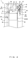
- FIG. 2 is a left side view illustrating the internal structure of the paper sheet storage apparatus 1.
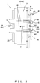
- FIG. 3 is a plan view illustrating the internal structure of the paper sheet storage apparatus 1.
- the paper sheet storage apparatus 1 includes a placement mount 10, a leading-edge position restriction guide 20, a sensor 30, a transportation unit 40, a rear-edge position restriction guide 50, a spacer 60, an open-close gate 70, and a pressing part 80. Note that indications of the rear-edge position restriction guide 50, the spacer 60, the open-close gate 70, and the pressing part 80 are omitted in FIG. 3 .
- the paper sheet storage apparatus 1 may be a bill storage cassette that can be attached to and detached from the paper sheet handling apparatus 100 depicted in FIG. 1 .
- the paper sheet storage apparatus 1 may be integral with, i.e., incapable of being detached from, the paper sheet handling apparatus 100.
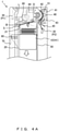
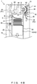
- the placement mount 10 can be lifted or lowered to a height H0 indicated in FIGS. 2 and 3 , a height H1 indicated in FIG. 4A less than the height H0, or a height H2 indicated in FIGS. 4B and 4C less than the height H1.
- Bills B may be placed on the placement mount 10.
- the leading-edge position restriction guide 20 is located on the downstream side in an entering direction D in which a bill B advances when being transported onto the placement mount 10 (located on the left side in FIG. 2 ), and restricts the position of the leading edge portion of the bill B.
- An uneven surface 21 is formed on a surface of the leading-edge position restriction guide 20 that contacts (a) bill(s) B.
- the uneven surface 21 is provided to prevent a bill B transported by the transportation unit 40 from entering the space between the leading-edge position restriction guide 20 and a plurality of bills B on the placement mount 10 depicted in FIG. 4A .
- the uneven surface 21 may be a jagged surface.
- the sensor 30 detects the presence/absence of an accumulation space S (indicated by a two-dot dash line) for bills B that is located above the placement mount 10.
- the sensor 30 detects the presence/absence of an accumulation space S by using detection light L emitted to a space between a first position P1 that is located on an opposite side of the leading-edge position restriction guide 20 from the bills B on the placement mount 10 (located on the left side in FIG. 2 ) and a second position P2 below the first position P1 that is located on an opposite side of the bills B on the placement mount 10 from the leading-edge position restriction guide 20 (located on the right side in FIG. 2 ).
- the sensor 30 may include an emission unit that is disposed at either of the first position P1 and the second position P2 and emits detection light L, and a light reception unit that is disposed at the other of the first position P1 and the second position P2 and receives the detection light L.
- the first position P1 may be located above the upper edge of the accumulation space S (e.g., above the lower edge of the transportation roller 44).
- Detection light L may be emitted to travel above the accumulation space S from the leading-edge side of bills B on the placement mount 10.
- the orientation of detection light L (sensor 30) is set such that the accumulation space S ensures a sufficient space for preventing a bill B from causing a jam.
- the transportation unit 40 includes transportation rollers 41-44 and impellers 45. As depicted in FIG. 3 , two transportation rollers 41, two transportation rollers 42, two transportation rollers 43, and two transportation rollers 44 are arranged in the width direction W of a bill B that is orthogonal to the entering direction D. Four impellers 45 are arranged in the width direction W of a bill B.
- the transportation unit 40 transports the bill B, which is transported from the transportation path 160 depicted in FIG. 1 , onto the placement mount 10.
- the transportation unit 40 transports the bill B from the placement mount 10 to the transportation path 160.
- the transportation roller 41 is a driven roller disposed to face the transportation roller 42, which is a driving roller.
- the transportation roller 41 rotates in accordance with a rotation of the transportation roller 42.
- the transportation roller 42 is a driving roller that rotates through a driving operation using the same driving source as the transportation roller 44.
- a transmission belt (not illustrated) covers the central shaft of the transportation roller 42 and the central shaft of the transportation roller 44.
- the two transportation rollers 42 each include two rollers adjacent to each other in the width direction W of bills B that is orthogonal to the entering direction D of the bills B.
- the rollers on the outsides in the width direction W may serve to separate a bill B when the bill B is being drawn out.
- the transportation roller 43 is disposed below the transportation roller 41. As with the transportation roller 41, the transportation roller 43 is a driven roller that is disposed to face the transportation roller 42 and rotates in accordance with a rotation of the transportation roller 42.
- the transportation roller 44 is a driving roller that rotates through a driving operation using the same driving source as the transportation roller 42.
- the transportation roller 44 is disposed to be swingable with respect to the central shaft of the transportation roller 42 and biased downward by a biasing member (not illustrated) .
- the transportation roller 44 draws out the bill B while being lifted by being pressed upward by the bill B against the biasing force of the biasing member.
- the impeller 45 is disposed below the transportation roller 42.
- the impeller 45 slaps, by using a plurality of blades, downward the rear edge portion of a bill B transported from between the transportation rollers 42 and 43 toward the placement mount 10, so as to prevent collision of the following bill.
- the rear-edge position restriction guide 50 is disposed to face the leading-edge position restriction guide 20 and restricts the position of the rear edge portion of a bill B.
- the rear-edge position restriction guide 50 includes a transportation guide section 51.
- the transportation guide section 51 extends upward to guide a bill B transported by the transportation unit 40.
- the transportation guide section 51 is provided with a through hole or a notch (not illustrated) for preventing interference with the transportation rollers 41 and 43.
- the spacer 60 is disposed between the open-close gate 70 and the leading-edge position restriction guide 20 and defines a position for the leading-edge position restriction guide 20 in accordance with the size of bills B.
- the open-close gate 70 closes the paper sheet storage apparatus 1 in an openable manner.
- the pressing part 80 may be disposed to be swingable with respect to the central shaft of the transportation roller 42 and lowered under the weight thereof to the position indicated in FIG. 2 .
- the pressing part 80 is pressed upward by the bills B on the placement mount 10.
- the pressing part 80 may also function as a guide for preventing the bill B from entering the space upward of the leading-edge position restriction guide 20.
- the pressing part 80 is disposed at a position in the width direction W of bills B at which the pressing part 80 does not interfere with detection light L, or includes a through hole through which detection light L passes.
- FIGS. 4A-4C are explanatory diagrams for the detecting of the presence/absence of an accumulation space S in the paper sheet storage apparatus 1 in accordance with embodiments.
- a bill B is transported by the transportation unit 40 in the entering direction D onto the placement mount 10, comes into contact with the uneven surface 21 of the leading-edge position restriction guide 20, and is placed on the placement mount 10.
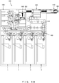
- FIGS. 5A -5F are explanatory diagrams for processing performed by the paper sheet handling apparatus 100 in accordance with embodiments.
- a plurality of bills B1 inserted into the money reception-ejection unit 110 by, for example, a customer are, as indicated in FIG. 5A , temporarily stored in the separation unit 120, then lowered within the separation unit 120, and transported one by one to the validation unit 130.
- the number of bills B1 may be counted when the bills B1 are being transported one by one from the separation unit 120. Then, bills B1 undergo validation performed by the validation unit 130 and are transported to the temporary retention unit 140 (bills B2).
- bill B2 transported to the temporary retention unit 140 has been determined to be abnormal by the validation unit 130 and thus should be returned, the bill B2 will be, as indicated in FIG. 5B , transported to the money reception-ejection unit 110 (bill B3).
- the bills B2 transported to the temporary retention unit 140 have been determined to be normal by the validation unit 130, the bills B2 will, as indicated in FIG. 5C , be transported to the separation unit 120 again, pass the validation unit 130, and be transported to paper sheet storage apparatuses 1 for, for example, corresponding denominations (bills B4 and B5).
- a bill determined to be abnormal by the validation unit 130 is transported to the reject unit 150.
- bills B4 and B5 drawn out of paper sheet storage apparatuses 1 pass the validation unit 130 and are transported to the temporary retention unit 140 (bills B6), as indicated in FIG. 5D .
- a bill determined to be abnormal by the validation unit 130 is transported to the reject unit 150.
- a bill B6 transported to the temporary retention unit 140 is transported to the money reception-ejection unit 110 (bill B7) and ejected.
- the paper sheet storage apparatus 1 includes: the placement mount 10 on which a bill B, i.e., an example of the paper sheet, is placed; the leading-edge position restriction guide 20 that restricts the position of the leading edge portion of a bill B in the entering direction D in which the bill B advances when being transported onto the placement mount 10; and the sensor 30 that detects the presence/absence of an accumulation space S for bills B that is located above the placement mount 10.
- the sensor 30 detects the presence/absence of an accumulation space S by using detection light L emitted to a space between a first position P1 that is located on an opposite side of the leading-edge position restriction guide 20 from the bills B on the placement mount 10 and a second position P2 below the first position P1 that is located on an opposite side of the bills B on the placement mount 10 from the leading-edge position restriction guide 20.
- detection light L is emitted to the space between the first position P1 that is located on an opposite side of the leading-edge position restriction guide 20 from the bills B on the placement mount 10 and the second position P2 located obliquely downward of the first position P1. Accordingly, if a bill B on the placement mount 10 slightly leans, as depicted in FIG. 4B , against the leading-edge position restriction guide 20 and a sufficient accumulation space S is present, it is possible to suppress an erroneous detection that a sufficient accumulation space S is not present, unlike in the case of the sensor 230 of the paper sheet storage apparatus 201 in accordance with the reference art depicted in FIG. 6 that horizontally emits detection light L.
- the first position P1 for the sensor 30 is located on the opposite side of the leading-edge position restriction guide 20 from the bills B on the placement mount 10, so in comparison to when the first position P1 is located above the placement mount 10, it can be detected that a sufficient accumulation space S is not present on the leading-edge side of bills B due to, for example, a bill B leaning against the leading-edge position restriction guide 20, thereby suppressing a fault such as a jam from occurring.
- embodiments allow the accuracy in detecting the presence/absence of an accumulation space S for bills B to be enhanced.
- the first position P1 is located above the accumulation space S. Accordingly, if a bill B on the placement mount 10 slightly leans, as depicted in FIG. 4B , against the leading-edge position restriction guide 20 and a sufficient accumulation space S is present, it is possible to more reliably suppress an erroneous detection that a sufficient accumulation space S is not present.
- detection light L is emitted to travel above the accumulation space S from the leading-edge side of bills B on the placement mount 10. In this way, it can be more reliably detected that a sufficient space S is not present on the leading-edge side of bills B due to, for example, a bill B leaning against the leading-edge position restriction guide 20.
Landscapes
- Physics & Mathematics (AREA)
- General Physics & Mathematics (AREA)
- Engineering & Computer Science (AREA)
- Mechanical Engineering (AREA)
- Pile Receivers (AREA)
- Controlling Sheets Or Webs (AREA)
Abstract
Description
- The present invention relates to a paper sheet storage apparatus for storing paper sheets, and a paper sheet handling apparatus including the paper sheet storage apparatus.
- Paper sheet handling apparatuses such as automated teller machines (ATMs) have conventionally included paper sheet storage apparatuses for storing paper sheets such as bills, checks, or valuable paper. For example, the paper sheet storage apparatus may be an attachable/detachable bill storage cassette. A paper sheet storage apparatus may include, for example, a bill storage cassette for each denomination.
- Such paper sheet storage apparatuses may use a sensor that emits, to a space between a position above a placement mount on which bills are placed and a position below a transportation unit for transporting bills onto the placement mount, detection light for determining the presence/absence of an accumulation space in accordance with whether the detection light is blocked by bills (see, for example, Patent document 1).
- Patent document 1:
Japanese Patent No. 4877124 -
FIG. 6 is a left side view illustrating the internal structure of a papersheet storage apparatus 201 in accordance with a reference art. - The paper
sheet storage apparatus 201 includes aplacement mount 210, a leading-edgeposition restriction guide 220, asensor 230, and atransportation unit 240. - The
placement mount 210 can be lifted or lowered and has bills B placed thereon. - The leading-edge
position restriction guide 220 restricts the position of the leading edge portion of a bill B in an entering direction D in which the bill B advances when being transported onto theplacement mount 210. - The
sensor 230 detects the presence/absence of an accumulation space S (indicated by a two-dot dash line) for bills B that is located above theplacement mount 210. For example, thesensor 230 may include an emission unit for horizontally emitting detection light L and a light reception unit for receiving the detection light L. - The
transportation unit 240 includes a plurality of rollers and an impeller and transports a bill B in the entering direction D onto theplacement mount 210. - In the paper
sheet storage apparatus 201, if a bill B leans, as depicted inFIG. 6 , against the leading-edgeposition restriction guide 220, the horizontal detection light L will be blocked by the bill B, like when there are several tens to hundreds of bills B, despite the presence of the sufficient accumulation space S. Thus, thesensor 230 will detect that a sufficient accumulation space S is not present. Likewise, if a bill B is folded upward, thesensor 230 could detect that a sufficient accumulation space S is not present, despite the presence of the sufficient accumulation space S. - In the case of a sensor that, as described above, emits detection light to a space between a position above a placement mount on which bills are placed and a position below a transportation unit for transporting a bill onto the placement mount, if a plurality of bills lean against the leading-edge
position restriction guide 220 depicted inFIG. 6 , such a sensor would not be capable of detecting that there is no accumulation space on the leading-edge side of the bills. Thus, a fault such as jamming of a bill could occur. - An object of the present invention is to provide a paper sheet storage apparatus and a paper sheet handling apparatus that are capable of enhancing the accuracy in detecting the presence/absence of an accumulation space for paper sheets.
- In one aspect, a paper sheet storage apparatus includes: a placement mount on which paper sheets are placed; a leading-edge position restriction guide that restricts a position of a leading edge portion of a paper sheet in an entering direction in which the paper sheet advances when being transported onto the placement mount; and a sensor that detects presence/absence of an accumulation space for paper sheets that is located above the placement mount, wherein the sensor detects the presence/absence of the accumulation space by using detection light emitted to a space between a first position that is located on an opposite side of the leading-edge position restriction guide from the paper sheets on the placement mount and a second position below the first position that is located on an opposite side of the paper sheets on the placement mount from the leading-edge position restriction guide.
- In another aspect, a paper sheet handling apparatus includes: a transportation path for transporting a paper sheet; and a paper sheet storage apparatus that stores the paper sheet transported on the transportation path, wherein the paper sheet storage apparatus includes: a placement mount on which paper sheets are placed; a leading-edge position restriction guide that restricts a position of a leading edge portion of a paper sheet in an entering direction in which the paper sheet advances when being transported onto the placement mount; and a sensor that detects presence/absence of an accumulation space for paper sheets that is located above the placement mount, wherein the sensor detects the presence/absence of the accumulation space by using detection light emitted to a space between a first position that is located on an opposite side of the leading-edge position restriction guide from the paper sheets on the placement mount and a second position below the first position that is located on an opposite side of the paper sheets on the placement mount from the leading-edge position restriction guide.
- The above aspects allow the accuracy in detecting the presence/absence of an accumulation space for paper sheets to be enhanced.
-
-
FIG. 1 is a left side view illustrating the internal structure of a paper sheet handling apparatus in accordance with embodiments; -
FIG. 2 is a left side view illustrating the internal structure of a paper sheet storage apparatus in accordance with embodiments; -
FIG. 3 is a plan view illustrating the internal structure of a paper sheet storage apparatus in accordance with embodiments; -
FIG. 4A is an explanatory diagram for the detecting of the presence/absence of an accumulation space in a paper sheet storage apparatus in accordance with embodiments (example 1) ; -
FIG. 4B is an explanatory diagram for the detecting of the presence/absence of an accumulation space in a paper sheet storage apparatus in accordance with embodiments (example 2) ; -
FIG. 4C is an explanatory diagram for the detecting of the presence/absence of an accumulation space in a paper sheet storage apparatus in accordance with embodiments (example 3) ; -
FIG. 5A is an explanatory diagram for processing performed by a paper sheet handling apparatus in accordance with embodiments (example 1); -
FIG. 5B is an explanatory diagram for processing performed by a paper sheet handling apparatus in accordance with embodiments (example 2); -
FIG. 5C is an explanatory diagram for processing performed by a paper sheet handling apparatus in accordance with embodiments (example 3); -
FIG. 5D is an explanatory diagram for processing performed by a paper sheet handling apparatus in accordance with embodiments (example 4); -
FIG. 5E is an explanatory diagram for processing performed by a paper sheet handling apparatus in accordance with embodiments (example 5); and -
FIG. 6 is a left side view illustrating the internal structure of a paper sheet storage apparatus in accordance with a reference art. - The following describes a paper sheet storage apparatus and a paper sheet handling apparatus in accordance with embodiments by referring to the drawings.
-
FIG. 1 is a left side view illustrating the internal structure of a papersheet handling apparatus 100 in accordance with embodiments. - As depicted in
FIG. 1 , the papersheet handling apparatus 100 includes a plurality of papersheet storage apparatuses 1, a money reception-ejection unit 110, aseparation unit 120, avalidation unit 130, atemporary retention unit 140, areject unit 150, and atransportation path 160. For example, the papersheet handling apparatus 100 may be an automated teller machine (ATM) . - The money reception-
ejection unit 110 receives or ejects a bill B, i.e., an example of a paper sheet. The paper sheet may be another type of paper sheet such as a check or valuable paper. - The
separation unit 120 lifts bills B to an upper position at which a bill B is received from the money reception-ejection unit 110 or lowers bills B to a lower position at which a bill B is drawn out toward thevalidation unit 130. Theseparation unit 120 temporarily stores a bill B received by the money reception-ejection unit 110. - The
validation unit 130 performs validation of a bill B transported from theseparation unit 120. For example, thevalidation unit 130 may determine whether the bill B is normal on the basis of the authenticity, thickness, length, or deterioration thereof. - The
temporary retention unit 140 temporarily stores a bill B that has undergone validation performed by thevalidation unit 130. - The
reject unit 150 stores bills B not to be returned to customers, among bills B determined to be abnormal by thevalidation unit 130. - The
transportation path 160 is a transportation path for transporting bills B between the plurality of papersheet storage apparatuses 1, the money reception-ejection unit 110, theseparation unit 120, thevalidation unit 130, thetemporary retention unit 140, and thereject unit 150. Transportation members such as transportation rollers for transporting bills B are disposed on thetransportation path 160. -
FIG. 2 is a left side view illustrating the internal structure of the papersheet storage apparatus 1.
FIG. 3 is a plan view illustrating the internal structure of the papersheet storage apparatus 1. - As depicted in
FIG. 2 , the papersheet storage apparatus 1 includes aplacement mount 10, a leading-edgeposition restriction guide 20, asensor 30, atransportation unit 40, a rear-edgeposition restriction guide 50, aspacer 60, an open-close gate 70, and apressing part 80. Note that indications of the rear-edgeposition restriction guide 50, thespacer 60, the open-close gate 70, and thepressing part 80 are omitted inFIG. 3 . - For example, the paper
sheet storage apparatus 1 may be a bill storage cassette that can be attached to and detached from the papersheet handling apparatus 100 depicted inFIG. 1 . The papersheet storage apparatus 1 may be integral with, i.e., incapable of being detached from, the papersheet handling apparatus 100. - For example, the
placement mount 10 can be lifted or lowered to a height H0 indicated inFIGS. 2 and3 , a height H1 indicated inFIG. 4A less than the height H0, or a height H2 indicated inFIGS. 4B and4C less than the height H1. Bills B may be placed on theplacement mount 10. - The leading-edge
position restriction guide 20 is located on the downstream side in an entering direction D in which a bill B advances when being transported onto the placement mount 10 (located on the left side inFIG. 2 ), and restricts the position of the leading edge portion of the bill B. Anuneven surface 21 is formed on a surface of the leading-edgeposition restriction guide 20 that contacts (a) bill(s) B. Theuneven surface 21 is provided to prevent a bill B transported by thetransportation unit 40 from entering the space between the leading-edgeposition restriction guide 20 and a plurality of bills B on theplacement mount 10 depicted inFIG. 4A . For example, theuneven surface 21 may be a jagged surface. - The
sensor 30 detects the presence/absence of an accumulation space S (indicated by a two-dot dash line) for bills B that is located above theplacement mount 10. Thesensor 30 detects the presence/absence of an accumulation space S by using detection light L emitted to a space between a first position P1 that is located on an opposite side of the leading-edge position restriction guide 20 from the bills B on the placement mount 10 (located on the left side inFIG. 2 ) and a second position P2 below the first position P1 that is located on an opposite side of the bills B on the placement mount 10 from the leading-edge position restriction guide 20 (located on the right side inFIG. 2 ). For example, thesensor 30 may include an emission unit that is disposed at either of the first position P1 and the second position P2 and emits detection light L, and a light reception unit that is disposed at the other of the first position P1 and the second position P2 and receives the detection light L. The first position P1 may be located above the upper edge of the accumulation space S (e.g., above the lower edge of the transportation roller 44). Detection light L may be emitted to travel above the accumulation space S from the leading-edge side of bills B on theplacement mount 10. The orientation of detection light L (sensor 30) is set such that the accumulation space S ensures a sufficient space for preventing a bill B from causing a jam. - The
transportation unit 40 includes transportation rollers 41-44 andimpellers 45. As depicted inFIG. 3 , twotransportation rollers 41, twotransportation rollers 42, twotransportation rollers 43, and twotransportation rollers 44 are arranged in the width direction W of a bill B that is orthogonal to the entering directionD. Four impellers 45 are arranged in the width direction W of a bill B. - In the process of the paper
sheet storage apparatus 1 storing a bill B received by the papersheet handling apparatus 100, thetransportation unit 40 transports the bill B, which is transported from thetransportation path 160 depicted inFIG. 1 , onto theplacement mount 10. In the process of the papersheet storage apparatus 1 drawing out a bill B upon money ejection of the papersheet handling apparatus 100, thetransportation unit 40 transports the bill B from theplacement mount 10 to thetransportation path 160. - The
transportation roller 41 is a driven roller disposed to face thetransportation roller 42, which is a driving roller. Thetransportation roller 41 rotates in accordance with a rotation of thetransportation roller 42. - The
transportation roller 42 is a driving roller that rotates through a driving operation using the same driving source as thetransportation roller 44. A transmission belt (not illustrated) covers the central shaft of thetransportation roller 42 and the central shaft of thetransportation roller 44. As depicted inFIG. 3 , the twotransportation rollers 42 each include two rollers adjacent to each other in the width direction W of bills B that is orthogonal to the entering direction D of the bills B. For example, the rollers on the outsides in the width direction W may serve to separate a bill B when the bill B is being drawn out. - The
transportation roller 43 is disposed below thetransportation roller 41. As with thetransportation roller 41, thetransportation roller 43 is a driven roller that is disposed to face thetransportation roller 42 and rotates in accordance with a rotation of thetransportation roller 42. - The
transportation roller 44 is a driving roller that rotates through a driving operation using the same driving source as thetransportation roller 42. Thetransportation roller 44 is disposed to be swingable with respect to the central shaft of thetransportation roller 42 and biased downward by a biasing member (not illustrated) . In the process of the papersheet storage apparatus 1 drawing out a bill B, thetransportation roller 44 draws out the bill B while being lifted by being pressed upward by the bill B against the biasing force of the biasing member. - The
impeller 45 is disposed below thetransportation roller 42. Theimpeller 45 slaps, by using a plurality of blades, downward the rear edge portion of a bill B transported from between thetransportation rollers placement mount 10, so as to prevent collision of the following bill. - The rear-edge
position restriction guide 50 is disposed to face the leading-edgeposition restriction guide 20 and restricts the position of the rear edge portion of a bill B. The rear-edgeposition restriction guide 50 includes atransportation guide section 51. Thetransportation guide section 51 extends upward to guide a bill B transported by thetransportation unit 40. Thetransportation guide section 51 is provided with a through hole or a notch (not illustrated) for preventing interference with thetransportation rollers - The
spacer 60 is disposed between the open-close gate 70 and the leading-edgeposition restriction guide 20 and defines a position for the leading-edgeposition restriction guide 20 in accordance with the size of bills B. - The open-
close gate 70 closes the papersheet storage apparatus 1 in an openable manner. - For example, the
pressing part 80 may be disposed to be swingable with respect to the central shaft of thetransportation roller 42 and lowered under the weight thereof to the position indicated inFIG. 2 . When theplacement mount 10 is lifted, thepressing part 80 is pressed upward by the bills B on theplacement mount 10. When a bill B is being transported by thetransportation unit 40 onto theplacement mount 10, thepressing part 80 may also function as a guide for preventing the bill B from entering the space upward of the leading-edgeposition restriction guide 20. Thepressing part 80 is disposed at a position in the width direction W of bills B at which thepressing part 80 does not interfere with detection light L, or includes a through hole through which detection light L passes. -
FIGS. 4A-4C are explanatory diagrams for the detecting of the presence/absence of an accumulation space S in the papersheet storage apparatus 1 in accordance with embodiments. - As indicated in
FIG. 4A , a bill B is transported by thetransportation unit 40 in the entering direction D onto theplacement mount 10, comes into contact with theuneven surface 21 of the leading-edgeposition restriction guide 20, and is placed on theplacement mount 10. - If a bill B on the
placement mount 10 slightly leans, as depicted inFIG. 4B , against the leading-edgeposition restriction guide 20 or if a bill B placed on theplacement mount 10 is folded upward (this situation is not illustrated), detection light L will not be blocked by the bill B, so thesensor 30 detects that there is a sufficient accumulation space S, unlike thesensor 230 of the papersheet storage apparatus 201 in accordance with the reference art depicted inFIG. 6 . - By contrast, if, as depicted in
FIG. 4C , a bill B leaning against the leading-edge position restriction guide 20 lifts thepressing part 80 and the leading edge portion of the bill B reaches a position above the lower edge of thetransportation roller 44, i.e., above the position of the upper edge of an accumulation space S, thesensor 30 detects that a sufficient accumulation space S is not present. Thus, thetransportation unit 40 and thetransportation path 160 depicted inFIG. 1 stop transportation of bills B onto theplacement mount 10. Accordingly, owing to the bill B lifting thepressing part 80, the following bill B is not placed onto theplacement mount 10, thereby preventing a jam from occurring within thetransportation unit 40. -
FIGS. 5A -5F are explanatory diagrams for processing performed by the papersheet handling apparatus 100 in accordance with embodiments. - A plurality of bills B1 inserted into the money reception-
ejection unit 110 by, for example, a customer are, as indicated inFIG. 5A , temporarily stored in theseparation unit 120, then lowered within theseparation unit 120, and transported one by one to thevalidation unit 130. The number of bills B1 may be counted when the bills B1 are being transported one by one from theseparation unit 120. Then, bills B1 undergo validation performed by thevalidation unit 130 and are transported to the temporary retention unit 140 (bills B2). - If a bill B2 transported to the
temporary retention unit 140 has been determined to be abnormal by thevalidation unit 130 and thus should be returned, the bill B2 will be, as indicated inFIG. 5B , transported to the money reception-ejection unit 110 (bill B3). - When bills B2 transported to the
temporary retention unit 140 have been determined to be normal by thevalidation unit 130, the bills B2 will, as indicated inFIG. 5C , be transported to theseparation unit 120 again, pass thevalidation unit 130, and be transported to papersheet storage apparatuses 1 for, for example, corresponding denominations (bills B4 and B5). A bill determined to be abnormal by thevalidation unit 130 is transported to thereject unit 150. - In the ejecting of bills B, bills B4 and B5 drawn out of paper
sheet storage apparatuses 1 pass thevalidation unit 130 and are transported to the temporary retention unit 140 (bills B6), as indicated inFIG. 5D . A bill determined to be abnormal by thevalidation unit 130 is transported to thereject unit 150. - As indicated in
FIG. 5E , a bill B6 transported to thetemporary retention unit 140 is transported to the money reception-ejection unit 110 (bill B7) and ejected. - In the embodiments described so far, the paper
sheet storage apparatus 1 includes: theplacement mount 10 on which a bill B, i.e., an example of the paper sheet, is placed; the leading-edgeposition restriction guide 20 that restricts the position of the leading edge portion of a bill B in the entering direction D in which the bill B advances when being transported onto theplacement mount 10; and thesensor 30 that detects the presence/absence of an accumulation space S for bills B that is located above theplacement mount 10. Thesensor 30 detects the presence/absence of an accumulation space S by using detection light L emitted to a space between a first position P1 that is located on an opposite side of the leading-edge position restriction guide 20 from the bills B on theplacement mount 10 and a second position P2 below the first position P1 that is located on an opposite side of the bills B on the placement mount 10 from the leading-edgeposition restriction guide 20. - As described above, detection light L is emitted to the space between the first position P1 that is located on an opposite side of the leading-edge position restriction guide 20 from the bills B on the
placement mount 10 and the second position P2 located obliquely downward of the first position P1. Accordingly, if a bill B on theplacement mount 10 slightly leans, as depicted inFIG. 4B , against the leading-edgeposition restriction guide 20 and a sufficient accumulation space S is present, it is possible to suppress an erroneous detection that a sufficient accumulation space S is not present, unlike in the case of thesensor 230 of the papersheet storage apparatus 201 in accordance with the reference art depicted inFIG. 6 that horizontally emits detection light L. Moreover, the first position P1 for thesensor 30 is located on the opposite side of the leading-edge position restriction guide 20 from the bills B on theplacement mount 10, so in comparison to when the first position P1 is located above theplacement mount 10, it can be detected that a sufficient accumulation space S is not present on the leading-edge side of bills B due to, for example, a bill B leaning against the leading-edgeposition restriction guide 20, thereby suppressing a fault such as a jam from occurring. - Accordingly, embodiments allow the accuracy in detecting the presence/absence of an accumulation space S for bills B to be enhanced.
- In embodiments, the first position P1 is located above the accumulation space S. Accordingly, if a bill B on the
placement mount 10 slightly leans, as depicted inFIG. 4B , against the leading-edgeposition restriction guide 20 and a sufficient accumulation space S is present, it is possible to more reliably suppress an erroneous detection that a sufficient accumulation space S is not present. - In embodiments, detection light L is emitted to travel above the accumulation space S from the leading-edge side of bills B on the
placement mount 10. In this way, it can be more reliably detected that a sufficient space S is not present on the leading-edge side of bills B due to, for example, a bill B leaning against the leading-edgeposition restriction guide 20. - The present invention is not simply limited to the embodiments described herein. Components of the embodiments may be embodied in a varied manner in an implementation phase without departing from the gist of the invention. A plurality of components disclosed with reference to the described embodiments may be combined, as appropriate, to achieve various inventions. For example, all of the components indicated with reference to embodiments may be combined as appropriate. Accordingly, various variations and applications can be provided, as a matter of course, without departing from the gist of the invention.
-
- 1: Paper sheet storage apparatus
- 10: Placement mount
- 20: Leading-edge position restriction guide
- 21: Uneven surface
- 30: Sensor
- 40: Transportation unit
- 41-44: Transportation roller
- 45: Impeller
- 50: Rear-edge position restriction guide
- 51: Transportation guide section
- 60: Spacer
- 70: Open-close gate
- 80: Pressing part
- 100: Paper sheet handling apparatus
- 110: Money reception-ejection unit
- 120: Separation unit
- 130: Validation unit
- 140: Temporary retention unit
- 150: Reject unit
- 160: Transportation path
- B: Bill
- D: Entering direction
- L: Detection light
- P1: First position
- P2: Second position
- S: Accumulation space
- W: Width direction
Claims (4)
- A paper sheet storage apparatus comprising:a placement mount on which paper sheets are placed;a leading-edge position restriction guide that restricts a position of a leading edge portion of a paper sheet in an entering direction in which the paper sheet advances when being transported onto the placement mount; anda sensor that detects presence/absence of an accumulation space for paper sheets that is located above the placement mount, whereinthe sensor detects the presence/absence of the accumulation space by using detection light emitted to a space between a first position that is located on an opposite side of the leading-edge position restriction guide from the paper sheets on the placement mount and a second position below the first position that is located on an opposite side of the paper sheets on the placement mount from the leading-edge position restriction guide.
- The paper sheet storage apparatus of claim 1, wherein
the first position is located above the accumulation space. - The paper sheet storage apparatus of claim 2, wherein
the detection light is emitted to travel above the accumulation space from a leading-edge side of the paper sheets on the placement mount. - A paper sheet handling apparatus comprising:a transportation path for transporting a paper sheet; anda paper sheet storage apparatus that stores the paper sheet transported on the transportation path, whereinthe paper sheet storage apparatus includesa placement mount on which paper sheets are placed,a leading-edge position restriction guide that restricts a position of a leading edge portion of a paper sheet in an entering direction in which the paper sheet advances when being transported onto the placement mount, anda sensor that detects presence/absence of an accumulation space for paper sheets that is located above the placement mount, whereinthe sensor detects the presence/absence of the accumulation space by using detection light emitted to a space between a first position that is located on an opposite side of the leading-edge position restriction guide from the paper sheets on the placement mount and a second position below the first position that is located on an opposite side of the paper sheets on the placement mount from the leading-edge position restriction guide.
Applications Claiming Priority (1)
| Application Number | Priority Date | Filing Date | Title |
|---|---|---|---|
| PCT/JP2019/010994 WO2020188664A1 (en) | 2019-03-15 | 2019-03-15 | Paper sheet storage device and paper sheet processing device |
Publications (3)
| Publication Number | Publication Date |
|---|---|
| EP3939918A1 true EP3939918A1 (en) | 2022-01-19 |
| EP3939918A4 EP3939918A4 (en) | 2023-05-31 |
| EP3939918B1 EP3939918B1 (en) | 2025-08-20 |
Family
ID=72520717
Family Applications (1)
| Application Number | Title | Priority Date | Filing Date |
|---|---|---|---|
| EP19920088.2A Active EP3939918B1 (en) | 2019-03-15 | 2019-03-15 | Paper sheet storage device and paper sheet processing device |
Country Status (6)
| Country | Link |
|---|---|
| US (1) | US11727744B2 (en) |
| EP (1) | EP3939918B1 (en) |
| JP (1) | JP7101306B2 (en) |
| CN (1) | CN113382942B (en) |
| ES (1) | ES3053139T3 (en) |
| WO (1) | WO2020188664A1 (en) |
Family Cites Families (17)
| Publication number | Priority date | Publication date | Assignee | Title |
|---|---|---|---|---|
| JPS6211871Y2 (en) * | 1980-09-10 | 1987-03-23 | ||
| JPH01112475A (en) * | 1987-10-27 | 1989-05-01 | Fujitsu Ltd | System for managing number of bank notes in safe box |
| JP3062609B2 (en) * | 1998-06-26 | 2000-07-12 | 株式会社日立製作所 | Paper sheet stacking device and automatic paper sheet handling machine |
| JP4608814B2 (en) * | 2001-06-06 | 2011-01-12 | 沖電気工業株式会社 | Media processing device |
| JP4878516B2 (en) * | 2006-07-12 | 2012-02-15 | 日立オムロンターミナルソリューションズ株式会社 | Paper sheet stacking device |
| JP5045164B2 (en) * | 2007-03-13 | 2012-10-10 | 沖電気工業株式会社 | Automatic banknote deposit and withdrawal machine |
| JP4877124B2 (en) * | 2007-07-23 | 2012-02-15 | 沖電気工業株式会社 | Paper sheet processing equipment |
| JP2009046298A (en) * | 2007-08-23 | 2009-03-05 | Oki Electric Ind Co Ltd | Paper sheet accumulating device |
| CN101836239B (en) * | 2007-08-30 | 2012-09-05 | 光荣株式会社 | Paper sheet processor |
| JP5072517B2 (en) * | 2007-09-28 | 2012-11-14 | 日立オムロンターミナルソリューションズ株式会社 | Paper sheet stacking device, paper sheet handling device, and automatic cash transaction device |
| JP5868029B2 (en) * | 2010-08-19 | 2016-02-24 | 沖電気工業株式会社 | Paper sheet stacking device, automatic cash deposit / withdrawal device, and paper sheet stacking method |
| JP2012078981A (en) * | 2010-09-30 | 2012-04-19 | Fujitsu Frontech Ltd | Paper sheet processing apparatus |
| JP5760791B2 (en) * | 2011-07-22 | 2015-08-12 | 沖電気工業株式会社 | Banknote handling equipment |
| EP2879102A1 (en) * | 2013-12-02 | 2015-06-03 | Wincor Nixdorf International GmbH | Cash box and ATM |
| JP2016145065A (en) * | 2015-02-09 | 2016-08-12 | グローリー株式会社 | Paper sheet storage mechanism, paper sheet processing machine, and paper sheet storage method |
| JP6277324B2 (en) * | 2015-03-18 | 2018-02-07 | 富士通フロンテック株式会社 | Paper sheet handling equipment |
| WO2019150516A1 (en) * | 2018-01-31 | 2019-08-08 | 富士通フロンテック株式会社 | Paper sheet handling device and pld configuration method for paper sheet handling device |
-
2019
- 2019-03-15 CN CN201980090466.6A patent/CN113382942B/en active Active
- 2019-03-15 EP EP19920088.2A patent/EP3939918B1/en active Active
- 2019-03-15 JP JP2021506824A patent/JP7101306B2/en active Active
- 2019-03-15 WO PCT/JP2019/010994 patent/WO2020188664A1/en not_active Ceased
- 2019-03-15 ES ES19920088T patent/ES3053139T3/en active Active
-
2021
- 2021-07-22 US US17/382,633 patent/US11727744B2/en active Active
Also Published As
| Publication number | Publication date |
|---|---|
| JPWO2020188664A1 (en) | 2021-09-13 |
| US20210350652A1 (en) | 2021-11-11 |
| ES3053139T3 (en) | 2026-01-19 |
| WO2020188664A1 (en) | 2020-09-24 |
| EP3939918B1 (en) | 2025-08-20 |
| JP7101306B2 (en) | 2022-07-14 |
| CN113382942A (en) | 2021-09-10 |
| US11727744B2 (en) | 2023-08-15 |
| EP3939918A4 (en) | 2023-05-31 |
| CN113382942B (en) | 2025-06-06 |
Similar Documents
| Publication | Publication Date | Title |
|---|---|---|
| EP2110792B1 (en) | Sheets processing machine | |
| US9592978B2 (en) | Medium protection device and medium separating and stacking device | |
| EP2110352A1 (en) | Paper money feeder | |
| WO2016093218A1 (en) | Paper sheet processing device | |
| JP2014229185A (en) | Medium accumulation device and medium processor | |
| CN106062832A (en) | Bank notes handling apparatus | |
| US8931632B2 (en) | Jam reduction | |
| JP6532662B2 (en) | Sheet feeding mechanism and sheet processing apparatus | |
| US20190300311A1 (en) | Paper sheet handling apparatus and method for detecting foreign object | |
| US11989994B2 (en) | Bundle module of medium deposit device | |
| US11727744B2 (en) | Paper sheet storage apparatus and paper sheet handling apparatus | |
| US8348272B2 (en) | Sheets counting device | |
| JP6186004B2 (en) | Paper sheet stacking device and paper sheet handling device | |
| EP3263495B1 (en) | Ejecting damaged /deformed media | |
| US20240273962A1 (en) | Medium processing device and medium transaction device | |
| CN109979075B (en) | Paper money processing device | |
| JP2012141673A (en) | Paper sheet processor and method for preventing paper jam thereof | |
| JPWO2015133392A1 (en) | Paper sheet processing equipment | |
| KR100992078B1 (en) | Banknote Discharge Accelerator of Banknote Counter | |
| CN108510637B (en) | System and method for rejecting media items | |
| EP3321893B1 (en) | Paper sheet storage cassette and paper sheet handling machine | |
| JP7054150B2 (en) | Banknote payer and electronic equipment | |
| JP2004070647A (en) | Bill handling device | |
| JP2022095125A (en) | Banknote processor | |
| JP2002362827A (en) | Medium processing device |
Legal Events
| Date | Code | Title | Description |
|---|---|---|---|
| STAA | Information on the status of an ep patent application or granted ep patent |
Free format text: STATUS: THE INTERNATIONAL PUBLICATION HAS BEEN MADE |
|
| PUAI | Public reference made under article 153(3) epc to a published international application that has entered the european phase |
Free format text: ORIGINAL CODE: 0009012 |
|
| STAA | Information on the status of an ep patent application or granted ep patent |
Free format text: STATUS: REQUEST FOR EXAMINATION WAS MADE |
|
| 17P | Request for examination filed |
Effective date: 20210705 |
|
| AK | Designated contracting states |
Kind code of ref document: A1 Designated state(s): AL AT BE BG CH CY CZ DE DK EE ES FI FR GB GR HR HU IE IS IT LI LT LU LV MC MK MT NL NO PL PT RO RS SE SI SK SM TR |
|
| DAV | Request for validation of the european patent (deleted) | ||
| DAX | Request for extension of the european patent (deleted) | ||
| REG | Reference to a national code |
Ref country code: DE Ref legal event code: R079 Free format text: PREVIOUS MAIN CLASS: B65H0043080000 Ipc: B65H0031100000 Ref country code: DE Ref legal event code: R079 Ref document number: 602019074578 Country of ref document: DE Free format text: PREVIOUS MAIN CLASS: B65H0043080000 Ipc: B65H0031100000 |
|
| A4 | Supplementary search report drawn up and despatched |
Effective date: 20230502 |
|
| RIC1 | Information provided on ipc code assigned before grant |
Ipc: G07D 11/22 20190101ALI20230424BHEP Ipc: G07D 11/12 20190101ALI20230424BHEP Ipc: B65H 43/08 20060101ALI20230424BHEP Ipc: B65H 31/10 20060101AFI20230424BHEP |
|
| REG | Reference to a national code |
Free format text: PREVIOUS MAIN CLASS: B65H0031100000 Ipc: B65H0031260000 Ref country code: DE Ref legal event code: R079 Ref document number: 602019074578 Country of ref document: DE |
|
| RIC1 | Information provided on ipc code assigned before grant |
Ipc: G07D 11/22 20190101ALI20250304BHEP Ipc: G07D 11/12 20190101ALI20250304BHEP Ipc: B65H 43/08 20060101ALI20250304BHEP Ipc: B65H 31/10 20060101ALI20250304BHEP Ipc: B65H 31/26 20060101AFI20250304BHEP |
|
| GRAP | Despatch of communication of intention to grant a patent |
Free format text: ORIGINAL CODE: EPIDOSNIGR1 |
|
| STAA | Information on the status of an ep patent application or granted ep patent |
Free format text: STATUS: GRANT OF PATENT IS INTENDED |
|
| INTG | Intention to grant announced |
Effective date: 20250411 |
|
| GRAS | Grant fee paid |
Free format text: ORIGINAL CODE: EPIDOSNIGR3 |
|
| GRAA | (expected) grant |
Free format text: ORIGINAL CODE: 0009210 |
|
| STAA | Information on the status of an ep patent application or granted ep patent |
Free format text: STATUS: THE PATENT HAS BEEN GRANTED |
|
| AK | Designated contracting states |
Kind code of ref document: B1 Designated state(s): AL AT BE BG CH CY CZ DE DK EE ES FI FR GB GR HR HU IE IS IT LI LT LU LV MC MK MT NL NO PL PT RO RS SE SI SK SM TR |
|
| REG | Reference to a national code |
Ref country code: GB Ref legal event code: FG4D |
|
| REG | Reference to a national code |
Ref country code: CH Ref legal event code: EP |
|
| REG | Reference to a national code |
Ref country code: IE Ref legal event code: FG4D |
|
| REG | Reference to a national code |
Ref country code: DE Ref legal event code: R096 Ref document number: 602019074578 Country of ref document: DE |
|
| REG | Reference to a national code |
Ref country code: NL Ref legal event code: MP Effective date: 20250820 |
|
| PG25 | Lapsed in a contracting state [announced via postgrant information from national office to epo] |
Ref country code: IS Free format text: LAPSE BECAUSE OF FAILURE TO SUBMIT A TRANSLATION OF THE DESCRIPTION OR TO PAY THE FEE WITHIN THE PRESCRIBED TIME-LIMIT Effective date: 20251220 |
|
| PG25 | Lapsed in a contracting state [announced via postgrant information from national office to epo] |
Ref country code: NO Free format text: LAPSE BECAUSE OF FAILURE TO SUBMIT A TRANSLATION OF THE DESCRIPTION OR TO PAY THE FEE WITHIN THE PRESCRIBED TIME-LIMIT Effective date: 20251120 |
|
| REG | Reference to a national code |
Ref country code: LT Ref legal event code: MG9D |
|
| PG25 | Lapsed in a contracting state [announced via postgrant information from national office to epo] |
Ref country code: PT Free format text: LAPSE BECAUSE OF FAILURE TO SUBMIT A TRANSLATION OF THE DESCRIPTION OR TO PAY THE FEE WITHIN THE PRESCRIBED TIME-LIMIT Effective date: 20251222 |
|
| PG25 | Lapsed in a contracting state [announced via postgrant information from national office to epo] |
Ref country code: FI Free format text: LAPSE BECAUSE OF FAILURE TO SUBMIT A TRANSLATION OF THE DESCRIPTION OR TO PAY THE FEE WITHIN THE PRESCRIBED TIME-LIMIT Effective date: 20250820 |
|
| PG25 | Lapsed in a contracting state [announced via postgrant information from national office to epo] |
Ref country code: NL Free format text: LAPSE BECAUSE OF FAILURE TO SUBMIT A TRANSLATION OF THE DESCRIPTION OR TO PAY THE FEE WITHIN THE PRESCRIBED TIME-LIMIT Effective date: 20250820 Ref country code: HR Free format text: LAPSE BECAUSE OF FAILURE TO SUBMIT A TRANSLATION OF THE DESCRIPTION OR TO PAY THE FEE WITHIN THE PRESCRIBED TIME-LIMIT Effective date: 20250820 |
|
| PG25 | Lapsed in a contracting state [announced via postgrant information from national office to epo] |
Ref country code: GR Free format text: LAPSE BECAUSE OF FAILURE TO SUBMIT A TRANSLATION OF THE DESCRIPTION OR TO PAY THE FEE WITHIN THE PRESCRIBED TIME-LIMIT Effective date: 20251121 |
|
| REG | Reference to a national code |
Ref country code: ES Ref legal event code: FG2A Ref document number: 3053139 Country of ref document: ES Kind code of ref document: T3 Effective date: 20260119 |
|
| PG25 | Lapsed in a contracting state [announced via postgrant information from national office to epo] |
Ref country code: SE Free format text: LAPSE BECAUSE OF FAILURE TO SUBMIT A TRANSLATION OF THE DESCRIPTION OR TO PAY THE FEE WITHIN THE PRESCRIBED TIME-LIMIT Effective date: 20250820 |
|
| PG25 | Lapsed in a contracting state [announced via postgrant information from national office to epo] |
Ref country code: LV Free format text: LAPSE BECAUSE OF FAILURE TO SUBMIT A TRANSLATION OF THE DESCRIPTION OR TO PAY THE FEE WITHIN THE PRESCRIBED TIME-LIMIT Effective date: 20250820 |
|
| PG25 | Lapsed in a contracting state [announced via postgrant information from national office to epo] |
Ref country code: PL Free format text: LAPSE BECAUSE OF FAILURE TO SUBMIT A TRANSLATION OF THE DESCRIPTION OR TO PAY THE FEE WITHIN THE PRESCRIBED TIME-LIMIT Effective date: 20250820 Ref country code: BG Free format text: LAPSE BECAUSE OF FAILURE TO SUBMIT A TRANSLATION OF THE DESCRIPTION OR TO PAY THE FEE WITHIN THE PRESCRIBED TIME-LIMIT Effective date: 20250820 |
|
| PG25 | Lapsed in a contracting state [announced via postgrant information from national office to epo] |
Ref country code: RS Free format text: LAPSE BECAUSE OF FAILURE TO SUBMIT A TRANSLATION OF THE DESCRIPTION OR TO PAY THE FEE WITHIN THE PRESCRIBED TIME-LIMIT Effective date: 20251120 |
|
| REG | Reference to a national code |
Ref country code: AT Ref legal event code: MK05 Ref document number: 1827132 Country of ref document: AT Kind code of ref document: T Effective date: 20250820 |
|
| PG25 | Lapsed in a contracting state [announced via postgrant information from national office to epo] |
Ref country code: SM Free format text: LAPSE BECAUSE OF FAILURE TO SUBMIT A TRANSLATION OF THE DESCRIPTION OR TO PAY THE FEE WITHIN THE PRESCRIBED TIME-LIMIT Effective date: 20250820 |
|
| PG25 | Lapsed in a contracting state [announced via postgrant information from national office to epo] |
Ref country code: DK Free format text: LAPSE BECAUSE OF FAILURE TO SUBMIT A TRANSLATION OF THE DESCRIPTION OR TO PAY THE FEE WITHIN THE PRESCRIBED TIME-LIMIT Effective date: 20250820 |
|
| PG25 | Lapsed in a contracting state [announced via postgrant information from national office to epo] |
Ref country code: AT Free format text: LAPSE BECAUSE OF FAILURE TO SUBMIT A TRANSLATION OF THE DESCRIPTION OR TO PAY THE FEE WITHIN THE PRESCRIBED TIME-LIMIT Effective date: 20250820 |
|
| PG25 | Lapsed in a contracting state [announced via postgrant information from national office to epo] |
Ref country code: IT Free format text: LAPSE BECAUSE OF FAILURE TO SUBMIT A TRANSLATION OF THE DESCRIPTION OR TO PAY THE FEE WITHIN THE PRESCRIBED TIME-LIMIT Effective date: 20250820 |
|
| PG25 | Lapsed in a contracting state [announced via postgrant information from national office to epo] |
Ref country code: CZ Free format text: LAPSE BECAUSE OF FAILURE TO SUBMIT A TRANSLATION OF THE DESCRIPTION OR TO PAY THE FEE WITHIN THE PRESCRIBED TIME-LIMIT Effective date: 20250820 |
|
| PG25 | Lapsed in a contracting state [announced via postgrant information from national office to epo] |
Ref country code: SK Free format text: LAPSE BECAUSE OF FAILURE TO SUBMIT A TRANSLATION OF THE DESCRIPTION OR TO PAY THE FEE WITHIN THE PRESCRIBED TIME-LIMIT Effective date: 20250820 Ref country code: EE Free format text: LAPSE BECAUSE OF FAILURE TO SUBMIT A TRANSLATION OF THE DESCRIPTION OR TO PAY THE FEE WITHIN THE PRESCRIBED TIME-LIMIT Effective date: 20250820 |