EP3939900A1 - Label preparation machine, labeling apparatus having a label preparation machine, method of preparing labels and method of applying single label sheets onto receptacles - Google Patents
Label preparation machine, labeling apparatus having a label preparation machine, method of preparing labels and method of applying single label sheets onto receptacles Download PDFInfo
- Publication number
- EP3939900A1 EP3939900A1 EP20185889.1A EP20185889A EP3939900A1 EP 3939900 A1 EP3939900 A1 EP 3939900A1 EP 20185889 A EP20185889 A EP 20185889A EP 3939900 A1 EP3939900 A1 EP 3939900A1
- Authority
- EP
- European Patent Office
- Prior art keywords
- web
- light emitting
- emitting unit
- label
- cutting
- Prior art date
- Legal status (The legal status is an assumption and is not a legal conclusion. Google has not performed a legal analysis and makes no representation as to the accuracy of the status listed.)
- Withdrawn
Links
- 238000002372 labelling Methods 0.000 title claims abstract description 77
- 238000002360 preparation method Methods 0.000 title claims abstract description 51
- 238000000034 method Methods 0.000 title claims description 18
- 238000005034 decoration Methods 0.000 claims abstract description 51
- 239000000463 material Substances 0.000 claims abstract description 31
- 239000000049 pigment Substances 0.000 claims description 14
- 239000011159 matrix material Substances 0.000 claims description 4
- 230000003213 activating effect Effects 0.000 claims description 2
- 239000003292 glue Substances 0.000 description 10
- 235000013305 food Nutrition 0.000 description 4
- 230000004913 activation Effects 0.000 description 3
- 230000001419 dependent effect Effects 0.000 description 2
- 239000007788 liquid Substances 0.000 description 2
- XLYOFNOQVPJJNP-UHFFFAOYSA-N water Substances O XLYOFNOQVPJJNP-UHFFFAOYSA-N 0.000 description 2
- 229910000831 Steel Inorganic materials 0.000 description 1
- XAGFODPZIPBFFR-UHFFFAOYSA-N aluminium Chemical compound [Al] XAGFODPZIPBFFR-UHFFFAOYSA-N 0.000 description 1
- 229910052782 aluminium Inorganic materials 0.000 description 1
- 235000013405 beer Nutrition 0.000 description 1
- 235000013361 beverage Nutrition 0.000 description 1
- 239000011111 cardboard Substances 0.000 description 1
- 238000004140 cleaning Methods 0.000 description 1
- 239000002131 composite material Substances 0.000 description 1
- 239000003599 detergent Substances 0.000 description 1
- 239000008157 edible vegetable oil Substances 0.000 description 1
- 235000011389 fruit/vegetable juice Nutrition 0.000 description 1
- 239000011521 glass Substances 0.000 description 1
- 239000002480 mineral oil Substances 0.000 description 1
- 230000008520 organization Effects 0.000 description 1
- 239000011087 paperboard Substances 0.000 description 1
- 239000004033 plastic Substances 0.000 description 1
- 229920003023 plastic Polymers 0.000 description 1
- 150000003839 salts Chemical class 0.000 description 1
- 239000002453 shampoo Substances 0.000 description 1
- 235000014214 soft drink Nutrition 0.000 description 1
- 239000010959 steel Substances 0.000 description 1
- 235000013616 tea Nutrition 0.000 description 1
- 230000036962 time dependent Effects 0.000 description 1
- 238000011144 upstream manufacturing Methods 0.000 description 1
- 230000000007 visual effect Effects 0.000 description 1
- 239000011800 void material Substances 0.000 description 1
- 238000005406 washing Methods 0.000 description 1
Images


Classifications
-
- B—PERFORMING OPERATIONS; TRANSPORTING
- B65—CONVEYING; PACKING; STORING; HANDLING THIN OR FILAMENTARY MATERIAL
- B65C—LABELLING OR TAGGING MACHINES, APPARATUS, OR PROCESSES
- B65C9/00—Details of labelling machines or apparatus
- B65C9/08—Label feeding
- B65C9/18—Label feeding from strips, e.g. from rolls
- B65C9/1803—Label feeding from strips, e.g. from rolls the labels being cut from a strip
-
- B—PERFORMING OPERATIONS; TRANSPORTING
- B65—CONVEYING; PACKING; STORING; HANDLING THIN OR FILAMENTARY MATERIAL
- B65C—LABELLING OR TAGGING MACHINES, APPARATUS, OR PROCESSES
- B65C9/00—Details of labelling machines or apparatus
- B65C9/46—Applying date marks, code marks, or the like, to the label during labelling
-
- B—PERFORMING OPERATIONS; TRANSPORTING
- B65—CONVEYING; PACKING; STORING; HANDLING THIN OR FILAMENTARY MATERIAL
- B65C—LABELLING OR TAGGING MACHINES, APPARATUS, OR PROCESSES
- B65C9/00—Details of labelling machines or apparatus
- B65C9/08—Label feeding
- B65C9/18—Label feeding from strips, e.g. from rolls
- B65C9/1803—Label feeding from strips, e.g. from rolls the labels being cut from a strip
- B65C2009/1834—Details of cutting means
- B65C2009/1846—Laser
Definitions
- the presen"t invention relates to a label preparation machine for preparing decorated single label sheets.
- the present invention also relates to a labeling apparatus for applying decorated single label sheets onto receptacles, the labeling apparatus having a label preparation machine for preparing decorated single label sheets.
- the present invention also relates to a method of preparing decorated label sheets.
- the present invention also relates to a method of applying decorated single label sheets onto receptacles.
- Labeling machines for the application of decorated single label sheets onto receptacles such as bottles, containers, cans or the like are known.
- a typical type of labeling machine relies on using a continuous web of labeling material provided in the form of a roll.
- Such labeling apparatuses comprise at least a label preparation machine, which allows to obtain single label sheets from the web of labeling material, while the web of labeling material advances along a web advancement path. Therefore, the label preparation machine comprises a cutting unit for cutting the web of labeling material at a cutting station so as to obtain the single label sheets.
- a typical cutting unit comprises at least one blade and at least one counter-blade, which are configured to cut in cooperation the web of labeling material.
- One of the blade and the counter-blade is fixed and the other one is mounted to a roller rotatable around a respective rotation axis.
- An alternative cutting unit comprises a respective laser unit for cutting the web of labeling material by means of a laser light. Even though the use of such laser units allow for a flexible execution of the cutting steps in dependence of the advancing web of labeling material, it is also known that these laser units are, however, known to be rather bulky and occupy a significant space.
- the desire and need to personalize the information and the visual images provided on the single label sheets has grown.
- the personalization can e.g. be achieved by decorating the label sheets to be applied on the receptacles.
- some label preparation machines comprises a decoration unit configured to decorate the web of labeling material or the single label sheets at a decoration station, the decoration station being arranged upstream or downstream of the cutting station.
- Some known decoration units comprise a laser device configured to activate photoactivatable pigments, which are incorporated into the web of labeling material and consequently into the single label sheets.
- Other known decoration units comprise a laser device for ablating parts of the web of labeling material and/or the single label sheets so as to obtain the desired decoration.
- Number 1 in Figure 1 indicates as a whole a labeling apparatus for applying single label sheets 2 onto a plurality of receptacles.
- the receptacles can be of any type including bottles 3, jars, vessels, cans, containers or the like, in particular being made of base components, like glass, paper or cardboard, plastics, aluminum, steel, and composites.
- the receptacles are adapted to be filled and/or are filled with a pourable product, in particular a pourable food product and/or a pourable non-food product.
- bottles 2 adapted to be filled with any type of pourable food product such as carbonated liquids (e.g. sparkling water, soft drinks and beer), non-carbonated liquids (including still water, juices, teas, sport drinks, wine, edible oil, etc.) beverages containing pulps and granular media such as salt or sugar or bottles 2 being adapted to be filled with pourable non-food products such as (cleaning and/or washing) detergents, shampoo, shower gel, mineral oils and the like.
- carbonated liquids e.g. sparkling water, soft drinks and beer
- non-carbonated liquids including still water, juices, teas, sport drinks, wine, edible oil, etc.
- beverages containing pulps and granular media such as salt or sugar
- pourable non-food products such as (cleaning and/or washing) detergents, shampoo, shower gel, mineral oils and the like.
- the invention also relates to other types of receptacles. It should also be clear that the invention also relates to receptacles, which are adapted to
- each bottle 2 extends along a longitudinal axis and comprises a pouring/inlet opening allowing for the introduction and the outpouring of the pourable product respectively into and out of bottle 2.
- labeling apparatus 1 comprises at least:
- labeling apparatus 1 also comprises a glue application device 7 configured to apply glue onto web 13 and/or single label sheets 2 and/or bottles 3 at a glue application station for allowing attachment of single label sheets 2 onto bottles 3.
- glue application device 7 is configured to apply glue onto single label sheets 2 prior to their application onto bottles 3.
- conveyor device 4 comprises at least one conveying carousel 8 rotatable around a rotation axis A and a plurality of retaining units (not shown and known as such) mounted to conveying carousel 8 and configured to retain one respective bottle 3 during advancement of the respective bottle 3 along receptacles advancement path P.
- each retaining unit is also configured to execute a rotation of the respective bottle 3 around the respective longitudinal axis during application of the respective label sheet 2.
- labeling preparation machine 6 comprises at least:
- web 13 can already be partially decorated or web 13 can be completely void of any previous decoration.
- labeling apparatus in particular labeling preparation machine 6, comprises a control unit 16 configured to control operation of at least labeling preparation machine 6.
- labeling preparation machine 6 also comprises a conveying unit 17 configured to advance single label sheets 2 along a label advancement path R, in particular from decoration and cutting station 15 towards and/or to labeling station 5.
- labeling preparation machine 6 comprises a magazine unit 19 configured to host web 13, in particular in the form of a bobbin, at initial station 18.
- conveying device 12 comprises an auxiliary conveyor, in particular an auxiliary drum 23, for supporting transfer of web 13 and/or single label sheets 2 to conveying unit 17.
- auxiliary conveyor in particular an auxiliary drum 23, for supporting transfer of web 13 and/or single label sheets 2 to conveying unit 17.
- light emitting unit 14 is arranged such that, in use, light emitting unit 14 decorates and cuts web 13 while being advanced on auxiliary conveyor 23.
- conveying device 12 comprises a driven feed roller 24 configured to rotate about a respective rotation axis being interposed between initial station 18 and decoration and cutting station 15, and being configured to at least partially control advancement of web 13 along web advancement path Q; and
- conveying device 12 also comprises a buffer 26 configured to accumulate in a variable manner portions of web 13.
- buffer 26 is arranged between initial station 18 and decoration and cutting station 15, even more particular between initial station 18 and feed roller 24.
- conveying unit 17 comprises at least one transfer drum 27 rotatable around a rotation axis C configured to advance single label sheets 2 along at least a portion of label advancement path R, and in particular through the glue application station.
- the transfer drum 27 is configured to apply the label sheets 2 on respective receptacles 3 by means of the rotation of the transfer drum 27 on itself .
- light emitting unit 14 is configured to emit a(n) (electromagnetic) light beam, in particular a laser irradiation, for decorating and cutting web 13 at decoration and cutting station 15.
- decoration and cutting station 15 defines that the decoration and the cutting of web 13 occurs by a light beam, which is locally confined to the same area.
- a cutting station at which web 13 is cut and a decoration station at which web 13 is decorated coincide defining the common decoration and cutting station 15.
- label preparation machine 6 does not rely on two distinct and locally separated units, one for executing a decorating step at a decoration station and one for executing a cutting step at a cutting station distinct from the decoration station (i.e. the two separated units are arranged at two distinct and locally separated locations), but relies on one single light emitting unit 14 being arranged at a common decoration and cutting station 15, in particular being configured to emit the light beam, in particular the laser irradiation, both for decorating and cutting web 13.
- light emitting unit 14 is configured to execute, in particularly to alternately execute, a decorating step during which light emitting unit 14 emits the light beam, in particular the laser irradiation, for decorating the, in use, advancing web 13 and a cutting step for cutting the, in use, advancing web 13.
- web 13 comprises photoactive pigments 28 (see Figure 2 ).
- web 13 comprises one or more layers containing pigments 28.
- pigments 28 provided in web 13 are configured to change the respective color by receiving an electromagnetic activation energy in the form of a light beam, e.g. a laser irradiation.
- pigments 28 are in a deactivated state and can be controlled into at least one activated state upon the application of the electromagnetic activation energy leading to a change in the respective color.
- pigments 28 are transparent or white.
- Upon activation pigments 28 can change their respective color (e.g. from transparent to black or white or from white to black).
- the color in the deactivated state and the color in the activated state is dependent on the specific molecular structure of the specific pigments 28 chosen.
- the final color is defined by the total energy transferred to pigments 28 (e.g. allowing to obtain different gray shades or respective other color tonalities) in dependence of the total transferred energy.
- light emitting unit 14 is configured to activate the photoactive pigments of web 13 in order to decorate web 13.
- light emitting unit 14 is configured to ablate portions of web 13, in particular by means of the light beam, in particular the laser irradiation, in order to decorate web 13.
- light emitting unit 14 is configured to cut web 13 such to define simultaneously a trailing edge of one decorated single label sheet 2 and a leading edge of the successive single label sheet 2 (which, in use, has not yet been decorated) .
- light emitting unit 14 is configured to decorate the successive single label 2 prior to the execution of a second cutting step.
- the first cutting step defines the leading edge of the label sheet 2 to be decorated, which is still part of web 13 prior to the execution of the decorating step and prior to the second cutting step, which defines the trailing edge of the respective decorated single label sheet 2.
- light emitting unit 14 is configured to cut single label sheets 2 from the, in use, advancing web 13 by means of a single light pulse, in particular a single laser pulse.
- the light emitting unit 14, for each label sheet 2 is configured to define completely a leading edge of the respective label sheet 2 by emitting a single light pulse and to define completely a trailing edge of the same respective label sheet 2 by emitting another single light pulse.
- the defining of the leading edge and the trailing edge by respective single pulses improves the precision in the defining of the label edges, but requires more power with respect to using more than one pulse for each edge.
- a very compact label preparation machine comprising a light emitting unit 14 for single pulse cutting, by employing the same single pulse light emitting unit 14 also for decorating the web.
- control unit 16 is configured to control, in particular to alternately control, light emitting unit 14 into at least:
- control unit 16 is configured to control light emitting unit 14 into the decoration mode and the cutting mode for executing respectively one decorating step and one cutting step.
- light emitting unit 14 is configured to modulate a light (laser) beam power, in particular a power of the laser irradiation, in dependence on whether light emitting unit 14 is controlled in the cutting mode or decoration mode.
- a light (laser) beam power in particular a power of the laser irradiation
- light emitting unit 14 is configured such that the emitted light beam power, in particular the power of the emitted light, even more particular the emitted laser irradiation, is higher when light emitting unit 14 is controlled, in use, in the cutting mode than when being, in use, controlled in the decoration mode.
- light emitting unit 14 comprises one or more light emitting elements, in particular one or more laser light elements.
- the light emitting elements could be arranged in a group of light emitting elements and/or having a matrix organization.
- each light emitting element is configured to selectively emit one respective single light beam, in particular one respective single laser beam.
- the light beam emitted by light emitting unit 14 can be the result of one or more of the respective single light beams emitted, in use, by the one or more light emitting elements.
- the light emitting elements in particular the group of light emitting elements and/or the matrix of light emitting elements is transversally arranged with respect to an advancement direction D of, the, in use, at decoration and cutting station advancing web 13 (i.e. the group of light emitting elements and/or the matrix of light emitting elements is along a line and/or an area transversal to advancement direction D).
- light emitting unit 14 can direct its light emission on each single portion of web 13.
- one or more of the light emitting elements are mounted onto a support, the support being moveable along a direction transversal to advancement direction D.
- the support could be moved, in use, such to partially follow the advancement movement of web 13.
- labeling apparatus 1 applies at least one single label sheet 2 onto bottles 3 at labeling station 5.
- bottles 3 advance, in particular by means of conveyor device 4, along bottle advancement path P.
- glue application device 7 adds glue onto web 13 and/or single label sheets 2 and/or bottles 2.
- glue application device 7 adds glue onto single label sheets 2 during advancement of single label sheets 2 along label advancement path R.
- Single label sheets 2 are prepared from web 13 by labeling preparation machine 6.
- labeling preparation machine 6 decorates and cuts web 13 at decoration and cutting station 15.
- operation of labeling preparation machine 6 comprises at least the steps of:
- web 13 is continuously advanced along web advancement path P.
- web 13 advances from initial station 18 to decoration and cutting station 15.
- the advancement speed of web 13 is at least partially controlled by feed roller 24.
- control unit 16 controls, in particular alternatingly controls, light emitting unit 14 into the decoration mode or cutting mode.
- the step of decorating and the step of cutting are executed in an alternating manner.
- each one single label sheet 2 comprises, during advancement of web 13 along web advancement path Q:
- the decorating step is executed on web 13 and the respective single label sheet 2 is only obtained after the second cutting step, which separates the respective single label sheet 2 from the remaining web 13.
- light emitting unit 14 emits a light beam, in particular a laser beam.
- light emitting unit 14 modulates an emitted light beam power of the light beam in dependence on whether light emitting unit 14 executes the decorating step or the cutting step (or in other words, on whether light emitting unit 14 is controlled in the decoration mode or cutting mode).
- light emitting unit 14 modulates the emitted light beam power such that the emitted light beam power is higher when light emitting unit 14 executes the cutting step than when executing the decorating step.
- light emitting unit 14 emits the light beam for activating photoactive pigments 28 and/or for ablating portions of web 13.
- the light emitting unit 14 defines completely a leading edge of the respective label sheet 2 by emitting a single light pulse and defines completely a trailing edge of the same respective label sheet 2 by emitting another single light pulse.
- operation of label preparation machine 6 also comprises the step of advancing single label sheets 2 along label advancement path R.
- number 1' indicates an alternative embodiment of a labeling apparatus according to the present invention; as labeling apparatus 1' (only partially shown to the extend necessary for the understanding of the differences between labeling apparatus 1' and 1) is similar to labeling apparatus 1, the following description is limited to the differences between them, and using the same references, where possible, for identical or corresponding parts.
- labeling apparatus 1' differs from labeling apparatus 1 in comprising label preparation machine 6'.
- labeling preparation machine 6' is similar to label preparation machine 6, the following description is limited to the differences between them, and using the same references, where possible, for identical or corresponding parts.
- label preparation machine 6' differs from label preparation machine 6 in the position of decoration and cutting station 15. While light emitting unit 15 of label preparation machine 6 is arranged such that light emitting unit 14 is configured to decorate and cut web 13 while web 13 advances on auxiliary conveyor 23, light emitting unit 14 of label preparation machine 6' is arranged such that light emitting unit 14 is configured to decorate and cut web 13 while web 13 advances on conveying unit 17, in particular transfer drum 27.
- the decoration and cutting station 15 is on the transfer drum 27. This improves further reduces the mechanical complexity of the preparation machine 6'.
- the transfer drum 27 defines a part of the conveying device 12.
- labeling apparatus 1' is similar to labeling apparatus 1 and as operation of label preparation device 6' is similar to operation of label preparation device 6', we refer to the above provided description.
- light emission unit 14 being configured to execute both the decoration and the cutting, it is possible to both provide for a flexible cutting as the light emission unit 14 can be precisely controlled in dependence of the advancing web 13 and to optimize the space requirements.
- a further advantage resides in light emission unit 14 being configured to modulate the light beam power so as to adapt the operation to the cutting and decoration requirements. While the cutting needs to separate the single label sheets 2 from web 13, the decoration of web 13 requires leaving web 13 substantially intact.
- single label sheets 2 are of the "self-stick"-type.
- the present invention could, however, also work with single label sheets 2 of the "sleeve-label-type" or the "pressure-sensitive label-type".
- the base layer removably carrying the label layer would be left intact and only the label layer would be cut so as to obtain the single label sheets being separable from the base layer.
Landscapes
- Labeling Devices (AREA)
Abstract
There is described a label preparation machine (6) for preparing decorated single label sheets (2) . The label preparation machine (6) comprises a conveying device (12) configured to (continuously) advance a web (13) of labeling material along a web advancement path (Q) and a light emitting unit (14) configured to decorate the, in use, advancing web (13) of labeling material and to cut single label sheets (2) from the, in use, advancing web (13) of labeling material at a decoration and cutting station (15).
Description
- The presen"t invention relates to a label preparation machine for preparing decorated single label sheets.
- Advantageously, the present invention also relates to a labeling apparatus for applying decorated single label sheets onto receptacles, the labeling apparatus having a label preparation machine for preparing decorated single label sheets.
- Advantageously, the present invention also relates to a method of preparing decorated label sheets.
- Advantageously, the present invention also relates to a method of applying decorated single label sheets onto receptacles.
- Labeling machines for the application of decorated single label sheets onto receptacles such as bottles, containers, cans or the like are known.
- A typical type of labeling machine relies on using a continuous web of labeling material provided in the form of a roll. Such labeling apparatuses comprise at least a label preparation machine, which allows to obtain single label sheets from the web of labeling material, while the web of labeling material advances along a web advancement path. Therefore, the label preparation machine comprises a cutting unit for cutting the web of labeling material at a cutting station so as to obtain the single label sheets.
- A typical cutting unit comprises at least one blade and at least one counter-blade, which are configured to cut in cooperation the web of labeling material. One of the blade and the counter-blade is fixed and the other one is mounted to a roller rotatable around a respective rotation axis.
- An alternative cutting unit comprises a respective laser unit for cutting the web of labeling material by means of a laser light. Even though the use of such laser units allow for a flexible execution of the cutting steps in dependence of the advancing web of labeling material, it is also known that these laser units are, however, known to be rather bulky and occupy a significant space.
- Furthermore, in the recent years, the desire and need to personalize the information and the visual images provided on the single label sheets has grown. One reason resides in the need to offer to the final consumer more and more possibilities to personalize the final appearance of the receptacles e.g. so that the appearance comprises a particular image or a particular photography or a particular written message. A further reason is related to the requirement to increase traceability of the product packaged within the receptacles. The personalization can e.g. be achieved by decorating the label sheets to be applied on the receptacles.
- Therefore, some label preparation machines comprises a decoration unit configured to decorate the web of labeling material or the single label sheets at a decoration station, the decoration station being arranged upstream or downstream of the cutting station.
- Some known decoration units comprise a laser device configured to activate photoactivatable pigments, which are incorporated into the web of labeling material and consequently into the single label sheets.
- Other known decoration units comprise a laser device for ablating parts of the web of labeling material and/or the single label sheets so as to obtain the desired decoration.
- Even though the known label preparation machines and the respective methods of preparing decorated single label sheets work satisfyingly well, a desire is felt in the sector to further improve the label preparation machines and their methods of operation, in particular so as to optimize the extension of the label preparation machines.
- It is therefore an object of the present invention to provide in a straightforward and low-cost manner an improved label preparation machine.
- Advantageously, it is another object of the present invention to provide in a straightforward and low-cost manner an improved labeling apparatus.
- Advantageously, it is another object of the present invention to provide in a straightforward and low-cost manner an improved method of preparing decorated single label sheets.
- Advantageously, it is another object of the present invention to provide in a straightforward and low-cost manner an improved method of applying labels onto receptacles.
- According to the present invention, there is provided a label preparation machine as claimed in claim 1.
- According to the present invention, there is also provided a labeling apparatus according to claim 9.
- According to the present invention there is also provided a method of preparing decorated single label sheets according to claim 10.
- According to the present invention there is also provided a method of applying decorated single label sheets onto receptacles according to
claim 15. - Preferred embodiments of the labeling preparation machine, the labeling apparatus and the method of preparing decorated single label sheets are claimed in the respective dependent claims.
- Two non-limiting embodiments of the present invention will be described by way of example with reference to the accompanying drawings, in which:
-
Figure 1 is a schematic top view of a labeling apparatus having a label preparation machine according to a first embodiment of the present invention, with parts removed for clarity; -
Figure 2 is a schematic sectioned view of a web of labeling material used in the labeling apparatus ofFigure 1 , with parts removed for clarity; -
Figure 3 is a schematic view of a time-dependent power curve of a light beam used for the cutting and decoration of the web of labeling material, with parts removed for clarity; -
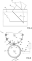
Figure 4 is a perspective view of a detail of the label preparation machine ofFigure 1 , with parts removed for clarity; and -
Figure 5 is a schematic top view of a portion of a labeling apparatus having a label preparation machine according to a second embodiment of the present invention, with parts removed for clarity. - Number 1 in
Figure 1 indicates as a whole a labeling apparatus for applyingsingle label sheets 2 onto a plurality of receptacles. - The receptacles can be of any
type including bottles 3, jars, vessels, cans, containers or the like, in particular being made of base components, like glass, paper or cardboard, plastics, aluminum, steel, and composites. - In particular, the receptacles are adapted to be filled and/or are filled with a pourable product, in particular a pourable food product and/or a pourable non-food product.
- In the following, we limit the description to the specific example of
bottles 2 adapted to be filled with any type of pourable food product such as carbonated liquids (e.g. sparkling water, soft drinks and beer), non-carbonated liquids (including still water, juices, teas, sport drinks, wine, edible oil, etc.) beverages containing pulps and granular media such as salt or sugar orbottles 2 being adapted to be filled with pourable non-food products such as (cleaning and/or washing) detergents, shampoo, shower gel, mineral oils and the like. However, it should be clear that the invention also relates to other types of receptacles. It should also be clear that the invention also relates to receptacles, which are adapted to be filled with other kinds of pourable products different from the above-mentioned ones. - In particular, each
bottle 2 extends along a longitudinal axis and comprises a pouring/inlet opening allowing for the introduction and the outpouring of the pourable product respectively into and out ofbottle 2. - With particular reference to
Figure 1 , labeling apparatus 1 comprises at least: - a
conveyor device 4 for advancingbottles 3 along a receptacle advancement path P and through alabeling station 5 at which at least onesingle label sheet 2 is applied onto each one of the advancingbottles 3; and - a
label preparation machine 6 for preparing decoratedsingle label sheets 2, and in particular for feeding decoratedsingle label sheets 2 towards and/or to labelingstation 5. - Preferentially, labeling apparatus 1 also comprises a
glue application device 7 configured to apply glue ontoweb 13 and/orsingle label sheets 2 and/orbottles 3 at a glue application station for allowing attachment ofsingle label sheets 2 ontobottles 3. In the specific case shown,glue application device 7 is configured to apply glue ontosingle label sheets 2 prior to their application ontobottles 3. - In more detail,
conveyor device 4 comprises at least one conveyingcarousel 8 rotatable around a rotation axis A and a plurality of retaining units (not shown and known as such) mounted to conveyingcarousel 8 and configured to retain onerespective bottle 3 during advancement of therespective bottle 3 along receptacles advancement path P. Preferentially, each retaining unit is also configured to execute a rotation of therespective bottle 3 around the respective longitudinal axis during application of therespective label sheet 2. - With particular reference to
Figure 1 ,labeling preparation machine 6 comprises at least: - a
conveying device 12 configured to (continuously) advance aweb 13 of labeling material along a web advancement path Q, in particular from aninitial station 18 to a decoration andcutting station 15; and - a
light emitting unit 14, in particular a laser light emitting unit, configured to decorate the, in use, advancingweb 13 and to cutsingle label sheets 2 from the, in use, advancingweb 13 at decoration andcutting station 15; in particularlight emitting unit 14 is arranged at decoration andcutting station 15. - It should be noted that
web 13 can already be partially decorated orweb 13 can be completely void of any previous decoration. - Preferentially, labeling apparatus 1, in particular
labeling preparation machine 6, comprises acontrol unit 16 configured to control operation of at leastlabeling preparation machine 6. - Preferentially,
labeling preparation machine 6 also comprises aconveying unit 17 configured to advancesingle label sheets 2 along a label advancement path R, in particular from decoration andcutting station 15 towards and/or to labelingstation 5. - Preferentially,
labeling preparation machine 6 comprises amagazine unit 19 configured to hostweb 13, in particular in the form of a bobbin, atinitial station 18. - According to the specific embodiment shown,
conveying device 12 comprises an auxiliary conveyor, in particular anauxiliary drum 23, for supporting transfer ofweb 13 and/orsingle label sheets 2 to conveyingunit 17. In particular,light emitting unit 14 is arranged such that, in use,light emitting unit 14 decorates and cutsweb 13 while being advanced onauxiliary conveyor 23. - In particular,
conveying device 12 comprises a drivenfeed roller 24 configured to rotate about a respective rotation axis being interposed betweeninitial station 18 and decoration andcutting station 15, and being configured to at least partially control advancement ofweb 13 along web advancement path Q; and - even more particular an
auxiliary roller 25, arranged adjacent, in particular tangential, to feedroller 24 for interposing, in use,web 13 betweenauxiliary roller 25 andfeed roller 24. - Preferentially,
conveying device 12 also comprises abuffer 26 configured to accumulate in a variable manner portions ofweb 13. In particular,buffer 26 is arranged betweeninitial station 18 and decoration and cuttingstation 15, even more particular betweeninitial station 18 andfeed roller 24. - With particular reference to
Figure 1 , conveyingunit 17 comprises at least onetransfer drum 27 rotatable around a rotation axis C configured to advancesingle label sheets 2 along at least a portion of label advancement path R, and in particular through the glue application station. - The
transfer drum 27 is configured to apply thelabel sheets 2 onrespective receptacles 3 by means of the rotation of thetransfer drum 27 on itself .Advantageously, light emittingunit 14 is configured to emit a(n) (electromagnetic) light beam, in particular a laser irradiation, for decorating and cuttingweb 13 at decoration and cuttingstation 15. - It should be noted that decoration and cutting
station 15 defines that the decoration and the cutting ofweb 13 occurs by a light beam, which is locally confined to the same area. In other words, a cutting station at whichweb 13 is cut and a decoration station at whichweb 13 is decorated coincide defining the common decoration and cuttingstation 15. - It should be noted that in contrast to the state-of-the-art machines known,
label preparation machine 6 does not rely on two distinct and locally separated units, one for executing a decorating step at a decoration station and one for executing a cutting step at a cutting station distinct from the decoration station (i.e. the two separated units are arranged at two distinct and locally separated locations), but relies on one singlelight emitting unit 14 being arranged at a common decoration and cuttingstation 15, in particular being configured to emit the light beam, in particular the laser irradiation, both for decorating and cuttingweb 13. - In particular, light emitting
unit 14 is configured to execute, in particularly to alternately execute, a decorating step during which light emittingunit 14 emits the light beam, in particular the laser irradiation, for decorating the, in use, advancingweb 13 and a cutting step for cutting the, in use, advancingweb 13. - According to one preferred non-limiting embodiment,
web 13 comprises photoactive pigments 28 (seeFigure 2 ). Preferably,web 13 comprises one or morelayers containing pigments 28. - Preferentially, pigments 28 provided in
web 13, are configured to change the respective color by receiving an electromagnetic activation energy in the form of a light beam, e.g. a laser irradiation. - In particular, pigments 28 are in a deactivated state and can be controlled into at least one activated state upon the application of the electromagnetic activation energy leading to a change in the respective color.
- Preferentially, when being in the deactivated state pigments 28 are transparent or white. Upon activation pigments 28 can change their respective color (e.g. from transparent to black or white or from white to black). In particular, the color in the deactivated state and the color in the activated state is dependent on the specific molecular structure of the
specific pigments 28 chosen. - Preferentially, the final color is defined by the total energy transferred to pigments 28 (e.g. allowing to obtain different gray shades or respective other color tonalities) in dependence of the total transferred energy.
- In particular, when using
web 13 comprisingphotoactive pigments 28,light emitting unit 14 is configured to activate the photoactive pigments ofweb 13 in order to decorateweb 13. - Alternatively or in addition, light emitting
unit 14 is configured to ablate portions ofweb 13, in particular by means of the light beam, in particular the laser irradiation, in order to decorateweb 13. - With particular reference to
Figure 4 ,light emitting unit 14 is configured to cutweb 13 such to define simultaneously a trailing edge of one decoratedsingle label sheet 2 and a leading edge of the successive single label sheet 2 (which, in use, has not yet been decorated) . - In particular, after the execution of a first cutting step,
light emitting unit 14 is configured to decorate the successivesingle label 2 prior to the execution of a second cutting step. In particular, the first cutting step defines the leading edge of thelabel sheet 2 to be decorated, which is still part ofweb 13 prior to the execution of the decorating step and prior to the second cutting step, which defines the trailing edge of the respective decoratedsingle label sheet 2. - Preferentially, light emitting
unit 14 is configured to cutsingle label sheets 2 from the, in use, advancingweb 13 by means of a single light pulse, in particular a single laser pulse. - The
light emitting unit 14, for eachlabel sheet 2, is configured to define completely a leading edge of therespective label sheet 2 by emitting a single light pulse and to define completely a trailing edge of the samerespective label sheet 2 by emitting another single light pulse. - The defining of the leading edge and the trailing edge by respective single pulses improves the precision in the defining of the label edges, but requires more power with respect to using more than one pulse for each edge.
- Therefore it is provided a very compact label preparation machine comprising a
light emitting unit 14 for single pulse cutting, by employing the same single pulselight emitting unit 14 also for decorating the web. - According to some preferred non-limiting embodiments,
control unit 16 is configured to control, in particular to alternately control,light emitting unit 14 into at least: - a decoration mode in which light emitting
unit 14 is configured to decorate the, in use, advancingweb 13 at decoration and cuttingstation 15; and - a cutting mode in which light emitting
unit 14 is configured to cut onesingle label sheet 2 from the, in use, advancingweb 13 at decoration and cuttingstation 15. - In other words,
control unit 16 is configured to control light emittingunit 14 into the decoration mode and the cutting mode for executing respectively one decorating step and one cutting step. - With particular reference to
Figure 3 ,light emitting unit 14 is configured to modulate a light (laser) beam power, in particular a power of the laser irradiation, in dependence on whether light emittingunit 14 is controlled in the cutting mode or decoration mode. - In particular, light emitting
unit 14 is configured such that the emitted light beam power, in particular the power of the emitted light, even more particular the emitted laser irradiation, is higher when light emittingunit 14 is controlled, in use, in the cutting mode than when being, in use, controlled in the decoration mode. - According to some preferred non-limiting embodiments,
light emitting unit 14 comprises one or more light emitting elements, in particular one or more laser light elements. The light emitting elements could be arranged in a group of light emitting elements and/or having a matrix organization. In particular, each light emitting element is configured to selectively emit one respective single light beam, in particular one respective single laser beam. Even more particular, in use, the light beam emitted by light emittingunit 14 can be the result of one or more of the respective single light beams emitted, in use, by the one or more light emitting elements. - Preferentially (see
Figure 4 ), the light emitting elements, in particular the group of light emitting elements and/or the matrix of light emitting elements is transversally arranged with respect to an advancement direction D of, the, in use, at decoration and cutting station advancing web 13 (i.e. the group of light emitting elements and/or the matrix of light emitting elements is along a line and/or an area transversal to advancement direction D). In this manner, light emittingunit 14 can direct its light emission on each single portion ofweb 13. - Alternatively or in addition, one or more of the light emitting elements are mounted onto a support, the support being moveable along a direction transversal to advancement direction D. In particular, the support could be moved, in use, such to partially follow the advancement movement of
web 13. - In use, labeling apparatus 1 applies at least one
single label sheet 2 ontobottles 3 atlabeling station 5. - In particular, during operation of labeling apparatus 1
bottles 3 advance, in particular by means ofconveyor device 4, along bottle advancement path P. - Preferentially,
glue application device 7 adds glue ontoweb 13 and/orsingle label sheets 2 and/orbottles 2. In the specific case disclosed,glue application device 7 adds glue ontosingle label sheets 2 during advancement ofsingle label sheets 2 along label advancement path R. -
Single label sheets 2 are prepared fromweb 13 bylabeling preparation machine 6. In particular,labeling preparation machine 6 decorates and cutsweb 13 at decoration and cuttingstation 15. - In more detail, operation of
labeling preparation machine 6 comprises at least the steps of: - advancing
web 13 along web advancement path P; - decorating the advancing
web 13 at decoration and cuttingstation 15 by operatinglight emitting unit 14; and - cutting
single label sheets 2 from the advancingweb 13 at decorating and cuttingstation 15 by operatinglight emitting unit 14. - In particular, during the step of advancing
web 13,web 13 is continuously advanced along web advancement path P. - Even more particular, during the step of advancing
web 13,web 13 advances frominitial station 18 to decoration and cuttingstation 15. - Preferentially, during the step of advancing
web 13, the advancement speed ofweb 13 is at least partially controlled byfeed roller 24. - According to some preferred non-limiting embodiments,
control unit 16 controls, in particular alternatingly controls, light emittingunit 14 into the decoration mode or cutting mode. - Preferentially, the step of decorating and the step of cutting are executed in an alternating manner.
- In particular, the preparation of each one
single label sheet 2 comprises, during advancement ofweb 13 along web advancement path Q: - a first cutting step, in particular thereby obtaining the leading edge of the respective
single label sheet 2; - the decorating step so as to decorate
web 13 on the respectivesingle label sheet 2; and - a second cutting step, in particular obtaining thereby the trailing edge of the respective
single label sheet 2. It should be noted that the second cutting step defines the first cutting step for obtaining the successivesingle label sheet 2. - It should be noted that the decorating step is executed on
web 13 and the respectivesingle label sheet 2 is only obtained after the second cutting step, which separates the respectivesingle label sheet 2 from the remainingweb 13. - In more detail, during the execution of the decorating step and the cutting step,
light emitting unit 14 emits a light beam, in particular a laser beam. - Furthermore, light emitting
unit 14 modulates an emitted light beam power of the light beam in dependence on whether light emittingunit 14 executes the decorating step or the cutting step (or in other words, on whether light emittingunit 14 is controlled in the decoration mode or cutting mode). - Preferentially, light emitting
unit 14 modulates the emitted light beam power such that the emitted light beam power is higher when light emittingunit 14 executes the cutting step than when executing the decorating step. - According to some possible non-limiting embodiments, during the decorating step,
light emitting unit 14 emits the light beam for activatingphotoactive pigments 28 and/or for ablating portions ofweb 13. - According to some possible embodiments, during the step of cutting, for each
label sheet 2, thelight emitting unit 14 defines completely a leading edge of therespective label sheet 2 by emitting a single light pulse and defines completely a trailing edge of the samerespective label sheet 2 by emitting another single light pulse. - According to some preferred non-limiting embodiment, operation of
label preparation machine 6 also comprises the step of advancingsingle label sheets 2 along label advancement path R. In particular, conveyingunit 17, even more particular conveyingdrum 27, advancessingle label sheets 2 from decoration and cuttingstation 15 tolabeling station 5. - With reference to
Figure 5 , number 1' indicates an alternative embodiment of a labeling apparatus according to the present invention; as labeling apparatus 1' (only partially shown to the extend necessary for the understanding of the differences between labeling apparatus 1' and 1) is similar to labeling apparatus 1, the following description is limited to the differences between them, and using the same references, where possible, for identical or corresponding parts. - In particular, labeling apparatus 1' differs from labeling apparatus 1 in comprising label preparation machine 6'.
- As labeling preparation machine 6' is similar to
label preparation machine 6, the following description is limited to the differences between them, and using the same references, where possible, for identical or corresponding parts. - In particular, label preparation machine 6' (only partially shown to the extend necessary for understanding the differences between label preparation machine 6' and 6) differs from
label preparation machine 6 in the position of decoration and cuttingstation 15. While light emittingunit 15 oflabel preparation machine 6 is arranged such thatlight emitting unit 14 is configured to decorate and cutweb 13 whileweb 13 advances onauxiliary conveyor 23,light emitting unit 14 of label preparation machine 6' is arranged such thatlight emitting unit 14 is configured to decorate and cutweb 13 whileweb 13 advances on conveyingunit 17, inparticular transfer drum 27. - In the machine 6', the decoration and cutting
station 15 is on thetransfer drum 27. This improves further reduces the mechanical complexity of the preparation machine 6'. - In machine 6', the
transfer drum 27 defines a part of the conveyingdevice 12. As operation of labeling apparatus 1' is similar to labeling apparatus 1 and as operation of label preparation device 6' is similar to operation of label preparation device 6', we refer to the above provided description. - The advantages of labeling apparatus 1 and/or
label preparation machine 6 and/or the methods according to the present invention will be clear from the foregoing description. - In particular, by providing for
light emission unit 14 being configured to execute both the decoration and the cutting, it is possible to both provide for a flexible cutting as thelight emission unit 14 can be precisely controlled in dependence of the advancingweb 13 and to optimize the space requirements. - A further advantage resides in
light emission unit 14 being configured to modulate the light beam power so as to adapt the operation to the cutting and decoration requirements. While the cutting needs to separate thesingle label sheets 2 fromweb 13, the decoration ofweb 13 requires leavingweb 13 substantially intact. - Clearly, changes may be made to labeling apparatus 1 and/or
label preparation machine 6 and/or the methods as described herein without, however, departing from the scope of protection as defined in the accompanying claims. - In the specific embodiment disclosed,
single label sheets 2 are of the "self-stick"-type. - The present invention could, however, also work with
single label sheets 2 of the "sleeve-label-type" or the "pressure-sensitive label-type". In this latter case, during the cutting step, the base layer removably carrying the label layer would be left intact and only the label layer would be cut so as to obtain the single label sheets being separable from the base layer.
Claims (9)
- A label preparation machine (6) for preparing decorated single label sheets (2) comprising:- a conveying device (12) configured to advance a web (13) of labeling material along a web advancement path (Q); and- a light emitting unit (14) configured to decorate the, in use, advancing web (13) of labeling material and to cut single label sheets (2) from the, in use, advancing web (13) of labeling material, at a decoration and cutting station (15); wherein:the machine (6) further comprises a control unit (16) configured to control, in particular to alternatingly control, the light emitting unit (14) into a decoration mode and a cutting mode;the light emitting unit (14) is configured to decorate the, in use, advancing web (13) of labeling material at the decoration and cutting station (15) when being controlled into the decoration mode and to cut one single label sheet (2) from, in use, advancing web (13) of labeling material at the decoration and cutting station (15) when being controlled into the cutting mode;the light emitting unit (14) is configured to modulate an emitted light beam power in dependence on whether the light emitting unit (14) is controlled in the cutting mode or in the decoration mode;the light emitting unit (14) is configured such that the emitted light beam power is higher when the light emitting unit (14) is controlled, in use, in the cutting mode than when being, in use, controlled in the decoration mode;the light emitting unit (14) is configured to activate photoactive pigments (28) of the web (13) of labeling material and/or to ablate portions of the web (13) of labeling material in order to decorate the web (13) of labeling material;the light emitting unit (14), for each label sheet (2), is configured to define completely a leading edge of the respective label sheet (2) by emitting a single light pulse and to define completely a trailing edge of the same respective label sheet by emitting another single light pulse.
- A label preparation machine (6) according to claim 1, further comprising a transfer drum (27) configured to apply the label sheets (2) on respective receptacles (3) by means of the rotation of the transfer drum (27) in itself.
- A label preparation machine according to claim 2, wherein the decoration and cutting station (15) is on said transfer drum (27).
- A label preparation machine according to any one of the previous claims, wherein, in use, the web (13) of labeling material advances at the decoration and cutting station (15) along an advancement direction (D).
- A label preparation machine (6) according to claim 4, wherein the light emitting unit (14) comprises a group of light emitting elements and/or a matrix of light emitting elements transversally arranged with respect to the advancement direction (D).
- A label preparation machine (6) according to claim 4, wherein the light emitting unit (14) comprises at least one light emitting element mounted onto a support being moveable along a direction transversal to the advancement direction (D).
- A labeling apparatus for applying at least one single label sheet (2) onto each one of a plurality of receptacles (3) comprising at least one label preparation machine (6) according to any one of the preceding claims for preparing the decorated single label sheets (2) to be applied onto the receptacles (3).
- Method of preparing decorated single label sheets (2), the method comprising:- advancing a web (13) of labeling material along a web advancement path (Q);- decorating the advancing web (13) of labeling material at a decoration and cutting station (15); and- cutting single label sheets (2) from the advancing web (13) of labeling material at the decorating and cutting station (15);wherein the step of decorating and the step of cutting are executed by a light emitting unit (14), arranged at the decorating and cutting station (15); wherein
during the step of advancing, the web (13) of labeling material is continuously advanced along the web advancement path (Q);
the step of decorating and the step of cutting are executed in an alternating manner;
during the decorating step and the cutting step the light emitting unit emits a light beam and modulates an emitted light beam power of the light beam in dependence on whether the light emitting unit (14) executes the decorating step or the cutting step;
the light emitting unit (14) modulates the emitted light beam power such that the emitted light beam power is higher when the light emitting unit (14) executes the cutting step than when executing the decorating step;
during the decorating step, the light emitting unit (14) emits a light beam for activating photoactive pigments (28) of the web (13) of labeling material and/or to ablate portions of the web (13) of labeling material;
for each label sheet (2), the light emitting unit (14) defines completely a leading edge of the respective label sheet (2) by emitting a single light pulse and defines completely a trailing edge of the same respective label sheet by emitting another single light pulse. - Method of labeling a plurality of receptacles (3), the method comprising the method of preparing according to claim 8 and a step of application, during which the decorated single labels (2) are applied at a labeling station (5) onto the receptacles (3).
Priority Applications (1)
| Application Number | Priority Date | Filing Date | Title |
|---|---|---|---|
| EP20185889.1A EP3939900A1 (en) | 2020-07-15 | 2020-07-15 | Label preparation machine, labeling apparatus having a label preparation machine, method of preparing labels and method of applying single label sheets onto receptacles |
Applications Claiming Priority (1)
| Application Number | Priority Date | Filing Date | Title |
|---|---|---|---|
| EP20185889.1A EP3939900A1 (en) | 2020-07-15 | 2020-07-15 | Label preparation machine, labeling apparatus having a label preparation machine, method of preparing labels and method of applying single label sheets onto receptacles |
Publications (1)
| Publication Number | Publication Date |
|---|---|
| EP3939900A1 true EP3939900A1 (en) | 2022-01-19 |
Family
ID=71620256
Family Applications (1)
| Application Number | Title | Priority Date | Filing Date |
|---|---|---|---|
| EP20185889.1A Withdrawn EP3939900A1 (en) | 2020-07-15 | 2020-07-15 | Label preparation machine, labeling apparatus having a label preparation machine, method of preparing labels and method of applying single label sheets onto receptacles |
Country Status (1)
| Country | Link |
|---|---|
| EP (1) | EP3939900A1 (en) |
Cited By (1)
| Publication number | Priority date | Publication date | Assignee | Title |
|---|---|---|---|---|
| IT202400012568A1 (en) * | 2024-06-03 | 2025-12-03 | Sacmi Verona Spa | LABELLING MACHINE AND PROCEDURE FOR APPLICATION OF LABELS TO CONTAINERS |
Citations (5)
| Publication number | Priority date | Publication date | Assignee | Title |
|---|---|---|---|---|
| US20100053299A1 (en) * | 2008-09-02 | 2010-03-04 | Govorkov Sergei V | Wide field diode-laser marker with swinging projection-optics |
| DE202013105749U1 (en) * | 2012-12-18 | 2014-04-01 | Sidel S.P.A. Con Socio Unico | Labeling unit for a labeling machine, labeling machine and improved label |
| WO2015159067A1 (en) * | 2014-04-16 | 2015-10-22 | Datalase Limited | Linerless label imaging and cutting |
| WO2018086712A1 (en) * | 2016-11-14 | 2018-05-17 | Sidel Participations | Labeling apparatus and method of operating such a labeling apparatus |
| EP3533720A1 (en) * | 2018-03-01 | 2019-09-04 | Sidel Participations | Labelling machine and method for applying label sheets onto receptacles |
-
2020
- 2020-07-15 EP EP20185889.1A patent/EP3939900A1/en not_active Withdrawn
Patent Citations (5)
| Publication number | Priority date | Publication date | Assignee | Title |
|---|---|---|---|---|
| US20100053299A1 (en) * | 2008-09-02 | 2010-03-04 | Govorkov Sergei V | Wide field diode-laser marker with swinging projection-optics |
| DE202013105749U1 (en) * | 2012-12-18 | 2014-04-01 | Sidel S.P.A. Con Socio Unico | Labeling unit for a labeling machine, labeling machine and improved label |
| WO2015159067A1 (en) * | 2014-04-16 | 2015-10-22 | Datalase Limited | Linerless label imaging and cutting |
| WO2018086712A1 (en) * | 2016-11-14 | 2018-05-17 | Sidel Participations | Labeling apparatus and method of operating such a labeling apparatus |
| EP3533720A1 (en) * | 2018-03-01 | 2019-09-04 | Sidel Participations | Labelling machine and method for applying label sheets onto receptacles |
Cited By (1)
| Publication number | Priority date | Publication date | Assignee | Title |
|---|---|---|---|---|
| IT202400012568A1 (en) * | 2024-06-03 | 2025-12-03 | Sacmi Verona Spa | LABELLING MACHINE AND PROCEDURE FOR APPLICATION OF LABELS TO CONTAINERS |
Similar Documents
| Publication | Publication Date | Title |
|---|---|---|
| CN1144732C (en) | Application of substances on a package | |
| CA2271141C (en) | Roll-fed labelling apparatus | |
| CA2564362C (en) | Method for the packaging of editorial products in plastic film and the relative packaging | |
| EP1163156B1 (en) | In line application of substances to solid objects | |
| EP3533720A1 (en) | Labelling machine and method for applying label sheets onto receptacles | |
| EP3272663B1 (en) | A labeling apparatus for labeling receptacles and a method for operating such a labeling apparatus | |
| WO2019121152A1 (en) | Labelling machine and labelling method for the application of label sheets on receptacles | |
| CN203958779U (en) | The unit of labelling, labeller and label for labeller | |
| US11174059B2 (en) | Decoration apparatus for decorating a web of labeling material and method of decorating a web of label material | |
| EP0928273A1 (en) | Label, tape and container carrier | |
| EP3150368B1 (en) | Apparatus and method for manufacturing discrete portions | |
| US20250178358A1 (en) | Decoration machine for decorating containers with movable laser decoration | |
| Kaye | Application of labels and sleeves | |
| EP4520674A1 (en) | Label transfer drum with single-piece pad devices for labelling containers by means of partial labels | |
| CN119497669A (en) | Decorating machine for decorating containers with a laser decorating unit equipped with a switching function | |
| JP7481961B2 (en) | Thick tack label | |
| WO2024079504A1 (en) | Labeling module with optimized start-up | |
| EP3728053A1 (en) | Labeling machine and labeling method | |
| WO2024153313A1 (en) | Capping machine with output in line cap decoration | |
| Fairley | Paper labels | |
| WO2024223453A3 (en) | Packaging machine and labelling device | |
| MXPA00001796A (en) | Application of substances on a package | |
| WO2007039742A1 (en) | Web of printed matter coated with a thermo reactive adhesive and method of using the same |
Legal Events
| Date | Code | Title | Description |
|---|---|---|---|
| PUAI | Public reference made under article 153(3) epc to a published international application that has entered the european phase |
Free format text: ORIGINAL CODE: 0009012 |
|
| STAA | Information on the status of an ep patent application or granted ep patent |
Free format text: STATUS: THE APPLICATION HAS BEEN PUBLISHED |
|
| AK | Designated contracting states |
Kind code of ref document: A1 Designated state(s): AL AT BE BG CH CY CZ DE DK EE ES FI FR GB GR HR HU IE IS IT LI LT LU LV MC MK MT NL NO PL PT RO RS SE SI SK SM TR |
|
| STAA | Information on the status of an ep patent application or granted ep patent |
Free format text: STATUS: THE APPLICATION IS DEEMED TO BE WITHDRAWN |
|
| 18D | Application deemed to be withdrawn |
Effective date: 20220720 |