EP3939894A1 - Exterior aircraft light cover, exterior aircraft light comprising the same, and method of upgrading or maintaining an exterior aircraft light - Google Patents
Exterior aircraft light cover, exterior aircraft light comprising the same, and method of upgrading or maintaining an exterior aircraft light Download PDFInfo
- Publication number
- EP3939894A1 EP3939894A1 EP20186576.3A EP20186576A EP3939894A1 EP 3939894 A1 EP3939894 A1 EP 3939894A1 EP 20186576 A EP20186576 A EP 20186576A EP 3939894 A1 EP3939894 A1 EP 3939894A1
- Authority
- EP
- European Patent Office
- Prior art keywords
- light
- exterior aircraft
- aircraft light
- cover
- exterior
- Prior art date
- Legal status (The legal status is an assumption and is not a legal conclusion. Google has not performed a legal analysis and makes no representation as to the accuracy of the status listed.)
- Granted
Links
Images


Classifications
-
- B—PERFORMING OPERATIONS; TRANSPORTING
- B64—AIRCRAFT; AVIATION; COSMONAUTICS
- B64D—EQUIPMENT FOR FITTING IN OR TO AIRCRAFT; FLIGHT SUITS; PARACHUTES; ARRANGEMENT OR MOUNTING OF POWER PLANTS OR PROPULSION TRANSMISSIONS IN AIRCRAFT
- B64D47/00—Equipment not otherwise provided for
- B64D47/02—Arrangements or adaptations of signal or lighting devices
-
- B—PERFORMING OPERATIONS; TRANSPORTING
- B64—AIRCRAFT; AVIATION; COSMONAUTICS
- B64D—EQUIPMENT FOR FITTING IN OR TO AIRCRAFT; FLIGHT SUITS; PARACHUTES; ARRANGEMENT OR MOUNTING OF POWER PLANTS OR PROPULSION TRANSMISSIONS IN AIRCRAFT
- B64D47/00—Equipment not otherwise provided for
- B64D47/02—Arrangements or adaptations of signal or lighting devices
- B64D47/06—Arrangements or adaptations of signal or lighting devices for indicating aircraft presence
-
- B—PERFORMING OPERATIONS; TRANSPORTING
- B64—AIRCRAFT; AVIATION; COSMONAUTICS
- B64F—GROUND OR AIRCRAFT-CARRIER-DECK INSTALLATIONS SPECIALLY ADAPTED FOR USE IN CONNECTION WITH AIRCRAFT; DESIGNING, MANUFACTURING, ASSEMBLING, CLEANING, MAINTAINING OR REPAIRING AIRCRAFT, NOT OTHERWISE PROVIDED FOR; HANDLING, TRANSPORTING, TESTING OR INSPECTING AIRCRAFT COMPONENTS, NOT OTHERWISE PROVIDED FOR
- B64F5/00—Designing, manufacturing, assembling, cleaning, maintaining or repairing aircraft, not otherwise provided for; Handling, transporting, testing or inspecting aircraft components, not otherwise provided for
- B64F5/40—Maintaining or repairing aircraft
-
- F—MECHANICAL ENGINEERING; LIGHTING; HEATING; WEAPONS; BLASTING
- F21—LIGHTING
- F21S—NON-PORTABLE LIGHTING DEVICES; SYSTEMS THEREOF; VEHICLE LIGHTING DEVICES SPECIALLY ADAPTED FOR VEHICLE EXTERIORS
- F21S9/00—Lighting devices with a built-in power supply; Systems employing lighting devices with a built-in power supply
- F21S9/02—Lighting devices with a built-in power supply; Systems employing lighting devices with a built-in power supply the power supply being a battery or accumulator
- F21S9/03—Lighting devices with a built-in power supply; Systems employing lighting devices with a built-in power supply the power supply being a battery or accumulator rechargeable by exposure to light
- F21S9/037—Lighting devices with a built-in power supply; Systems employing lighting devices with a built-in power supply the power supply being a battery or accumulator rechargeable by exposure to light the solar unit and the lighting unit being located within or on the same housing
-
- F—MECHANICAL ENGINEERING; LIGHTING; HEATING; WEAPONS; BLASTING
- F21—LIGHTING
- F21V—FUNCTIONAL FEATURES OR DETAILS OF LIGHTING DEVICES OR SYSTEMS THEREOF; STRUCTURAL COMBINATIONS OF LIGHTING DEVICES WITH OTHER ARTICLES, NOT OTHERWISE PROVIDED FOR
- F21V23/00—Arrangement of electric circuit elements in or on lighting devices
- F21V23/003—Arrangement of electric circuit elements in or on lighting devices the elements being electronics drivers or controllers for operating the light source, e.g. for a LED array
-
- B—PERFORMING OPERATIONS; TRANSPORTING
- B64—AIRCRAFT; AVIATION; COSMONAUTICS
- B64D—EQUIPMENT FOR FITTING IN OR TO AIRCRAFT; FLIGHT SUITS; PARACHUTES; ARRANGEMENT OR MOUNTING OF POWER PLANTS OR PROPULSION TRANSMISSIONS IN AIRCRAFT
- B64D2203/00—Aircraft or airfield lights using LEDs
-
- B—PERFORMING OPERATIONS; TRANSPORTING
- B64—AIRCRAFT; AVIATION; COSMONAUTICS
- B64D—EQUIPMENT FOR FITTING IN OR TO AIRCRAFT; FLIGHT SUITS; PARACHUTES; ARRANGEMENT OR MOUNTING OF POWER PLANTS OR PROPULSION TRANSMISSIONS IN AIRCRAFT
- B64D47/00—Equipment not otherwise provided for
- B64D47/02—Arrangements or adaptations of signal or lighting devices
- B64D47/04—Arrangements or adaptations of signal or lighting devices the lighting devices being primarily intended to illuminate the way ahead
Definitions
- Exterior aircraft lights Almost all aircraft are equipped with exterior aircraft lights. In particular, large passenger air planes have a wide variety of exterior aircraft lights. Examples of such lighting devices include take-off and/or landing lights, taxi lights, navigation lights and anti-collision lights.
- the exterior aircraft light cover comprises a support portion, which is configured for supporting the light transmissive pane.
- the support portion may in particular be provided as a retainer or frame extending along the outer periphery of the light transmissive pane.
- Such a support portion provides a solid support of the light transmissive pane. It may also protect the outer periphery of the light transmissive pane from being damaged by mechanical impact.
- the exterior aircraft light cover comprises a controller which is configured for switching and/or dimming the at least one ancillary light source.
- a controller allows operating the exterior aircraft light cover independently of the aircraft to which it is mounted. It allows in particular switching the at least one ancillary light source of the exterior aircraft light cover autonomously, i.e. without receiving electric control signals via an electric connection with the aircraft.
- Such a configuration facilitates an easy replacing of a conventional exterior aircraft light cover, which does not comprise any ancillary light sources, with an exterior aircraft light cover according to an exemplary embodiment of the invention. No electric control signals for switching the at least one ancillary light source of the exterior aircraft light cover need to be supplied from the aircraft and/or from the exterior aircraft light to the controller.
- the at least one ancillary light source of the exterior aircraft light cover may for example be switched on if a light pattern, emitted by the targeted light source(s) of the exterior aircraft light, causes the at least one first photovoltaic device to receive more light than the second photovoltaic device; and/or the at least one ancillary light source of the exterior aircraft light cover may be switched off if a light pattern, generated by the targeted light source(s) of the exterior aircraft light, causes the at least one first photovoltaic device to receive less light than the second photovoltaic device.
- the at least one ancillary light source of the exterior aircraft light cover may be controlled, i.e. switched on and off, in dependence of the switching state of the exterior aircraft light, without providing an additional sensor(s) and without establishing any electrical connections between the exterior aircraft light cover and the exterior aircraft light.
- the exterior aircraft light is configured to selectively operate as a landing light or as a take-off light.
- the exterior aircraft light cover may be configured for detecting at least a portion of the light emitted by the targeted light sources of the exterior aircraft light, in order to switch on the at least one ancillary light source of the exterior aircraft light cover, when the exterior aircraft light is operated as a landing light, and in order to switch off the at least one ancillary light source of the exterior aircraft light cover, when the exterior aircraft light is operated as a take-off light.
- the sensor 32 and the controller 34 are operated with electric energy supplied by the photovoltaic devices 26, 28 and/or the at least one electric storage device 30 as well.
- Figure 7 illustrates the operation of the exterior aircraft light 2 during take-off.
- the landing light sources 4 are switched off, and the take-off light sources 6 are switched on.
- Figure 7 shows that during take-off, when the take-off light sources 6 are switched on, more light is reflected by the light transmissive pane 16 onto the second photovoltaic device 28 than onto the first photovoltaic device 26.
Landscapes
- Engineering & Computer Science (AREA)
- Aviation & Aerospace Engineering (AREA)
- General Engineering & Computer Science (AREA)
- Manufacturing & Machinery (AREA)
- Transportation (AREA)
- Life Sciences & Earth Sciences (AREA)
- Sustainable Development (AREA)
- Microelectronics & Electronic Packaging (AREA)
- Traffic Control Systems (AREA)
Abstract
Description
- The present invention relates to the field of aircraft lighting, in particular to a cover for an exterior aircraft light ("exterior aircraft light cover") and to an exterior aircraft light comprising such a cover. The invention further relates to an aircraft comprising such an exterior aircraft light and to a method of upgrading or maintaining an exterior aircraft light by replacing its exterior aircraft light cover.
- Almost all aircraft are equipped with exterior aircraft lights. In particular, large passenger air planes have a wide variety of exterior aircraft lights. Examples of such lighting devices include take-off and/or landing lights, taxi lights, navigation lights and anti-collision lights.
- It would be beneficial to improve the visibility of the exterior aircraft lights, in particular when the aircraft is located on the ground, for example for helping ground personnel to identify the aircraft and/or different portions of the aircraft unambiguously and more easily.
- Exemplary embodiments of the invention include an exterior aircraft light cover, which is configured to be mounted to an exterior aircraft light, comprising: a mounting portion, configured to be mounted to a housing of an exterior aircraft light ("exterior aircraft light housing"); a light transmissive pane, supported by the mounting portion, wherein the mounting portion and the light transmissive pane are configured to jointly close the exterior aircraft light housing; at least one photovoltaic device, which is configured for generating electric energy when illuminated; at least one electric storage device, which is configured for storing at least a portion of the electric energy generated by the at least one photovoltaic device; and at least one light source, which is operable with electric energy supplied by at least one of the at least one photovoltaic device and the at least one electric storage device.
- When an exterior aircraft light cover according to an exemplary embodiment of the invention is mounted to a housing of an exterior aircraft light, the visibility and identifiability of the exterior aircraft light may be improved, in particular in a dark environment, by operating the at least one light source of the exterior aircraft light cover. This helps ground personnel to identify the aircraft and/or the exterior aircraft light.
- The at least one light source of the exterior aircraft light cover is an ancillary light source, i.e. a light source which is provided in addition to at least one targeted light source of the exterior aircraft light, providing the intended functionality of the exterior aircraft light. In other words, the at least one ancillary light source of the exterior aircraft light cover is not identical with the at least one targeted light source, providing the intended functionality of the exterior aircraft light.
- Due to the at least one photovoltaic device and the at least one electric storage device, an exterior aircraft light cover according to an exemplary embodiment of the invention is operable without establishing any electric connections between the exterior aircraft light cover and the electric system of the aircraft. In consequence, a conventional exterior aircraft light cover, i.e. a light cover which covers the light sources of the exterior aircraft light device, but which does not comprise any ancillary light sources, may be replaced easily by an exterior aircraft light cover according to an exemplary embodiment of the invention without intervening with the electric system of the aircraft. As an exterior aircraft light cover according to an exemplary embodiment of the invention does not intervene with the electric system of the aircraft, the process of certifying such an exterior aircraft light cover for use in commercial aviation is considerably simplified, when compared to the process of certifying a component which does intervene with the electric system of the aircraft.
- In an exterior aircraft light cover according to an exemplary embodiment of the invention, the at least one electric storage device is repeatedly recharged with electric energy generated by the at least one photovoltaic device. In consequence, the at least one light source of the exterior aircraft light cover may be operated with high reliability and the exterior aircraft light cover requires only little maintenance.
- In an embodiment, the at least one ancillary light source of the exterior aircraft light cover is at least one LED or it may comprise at least one LED. LEDs provide reliable light sources, which may be operated with high efficiency, at comparable low costs. LEDs emitting light of basically any desired color used in aviation are commercially available.
- In an embodiment, the exterior aircraft light cover comprises a support portion, which is configured for supporting the light transmissive pane. The support portion may in particular be provided as a retainer or frame extending along the outer periphery of the light transmissive pane. Such a support portion provides a solid support of the light transmissive pane. It may also protect the outer periphery of the light transmissive pane from being damaged by mechanical impact.
- In an embodiment, the mounting portion is configured as a support portion for supporting the light transmissive pane. Integrating the support portion, supporting the light transmissive pane, with the mounting portion provides a compact exterior aircraft light cover, which may be produced at low costs.
- In an embodiment, the light transmissive pane is configured to allow light from within the exterior aircraft light, in particular light generated by at least one targeted light source of the exterior aircraft light, to pass through the light transmissive pane.
- In an embodiment, the light transmissive pane may be at least partially transparent. The light transmissive pane may comprise at least one light transmissive portion and at least one opaque portion, which is not light transmissive. A combination of light transmissive and opaque portions of the light transmissive pane may be employed for shaping the light output emitted by the exterior aircraft light according to the actual needs.
- In an alternative embodiment, the light transmissive pane may be light transmissive substantially across its whole spatial extension, allowing substantially all light emitted by the at least one targeted light source to pass through the light transmissive pane. In such a configuration, the light emitted by the at least one targeted light source is used very efficiently, as basically no light emitted by the at least one targeted light source is blocked by opaque portions of the light transmissive pane.
- In an embodiment, the light transmissive pane comprises a plurality of light transmissive portions having different colors. Such a light transmissive pane allows the exterior aircraft light to emit a light pattern including light of different colors, even if it does not comprise multi-colored targeted light sources.
- In an embodiment, the at least one photovoltaic device is arranged in a position in which it is, in operation, illuminated by light which is emitted by the at least one targeted light source of the exterior aircraft light and reflected by the light transmissive pane. The light emitted by the targeted light sources of the exterior aircraft light may in particular reflected towards the at least one photovoltaic device by Fresnel reflection.
- Such a configuration allows generating electric power, used for operating the exterior aircraft light cover, from light emitted by the targeted light sources when the exterior aircraft light is operated. In such a configuration, the generation of electric power does not depend on the presence of external ambient light, such as sun light. In consequence, electric power for operating the at least one light source of the exterior aircraft light cover is generated even at night, when no external ambient light is present.
- In an embodiment, the at least one photovoltaic device comprises at least one solar cell. Solar cells provide highly efficient photovoltaic devices. In order to enhance the efficiency even further, the photovoltaic devices / solar cells may be optimized to the wavelengths / spectrum of the light emitted by the at least one targeted light source.
- In an embodiment, the at least one electric storage device is electrically coupled to the at least one photovoltaic device and to the at least one ancillary light source. In such a configuration, at least a portion of the electric energy generated by the at least one photovoltaic device may be supplied to and stored within the at least one electric storage device. The electric energy stored within the at least one electric storage device may be supplied to the at least one ancillary light source for operating said ancillary light source. Such a configuration allows operating the at least one ancillary light source even in situations in which no electric power is generated by the at least one photovoltaic device since the at least one photovoltaic device is temporarily not illuminated. Also, such a configuration allows for providing highly stable power supply conditions from the at least one electric storage device to the at least one ancillary light source, e.g. via a power conditioning circuit interposed between the at least one electric storage device and the at least one ancillary light source.
- In an alternative embodiment, the at least one photovoltaic device is connected or connectable to the at least one ancillary light source for supplying energy generated by the at least one photovoltaic device directly to the at least one ancillary light source, i.e. without passing the electric energy through an electric storage device. In such a configuration the complexity and costs for providing an electric storage device may be saved. Further, the risk of malfunction due to a failure of the electric storage device is eliminated.
- In a further alternative embodiment, the at least one photovoltaic device is coupled to the at least one electric storage device and to the at least one ancillary light source. In this way, power may be directly supplied to the at least one ancillary light source, when needed, and may be stored in the at least one electric storage device, when not needed or not fully needed by the at least one ancillary light source.
- In an embodiment, the exterior aircraft light cover comprises a controller which is configured for switching and/or dimming the at least one ancillary light source. Such a controller allows operating the exterior aircraft light cover independently of the aircraft to which it is mounted. It allows in particular switching the at least one ancillary light source of the exterior aircraft light cover autonomously, i.e. without receiving electric control signals via an electric connection with the aircraft. Such a configuration facilitates an easy replacing of a conventional exterior aircraft light cover, which does not comprise any ancillary light sources, with an exterior aircraft light cover according to an exemplary embodiment of the invention. No electric control signals for switching the at least one ancillary light source of the exterior aircraft light cover need to be supplied from the aircraft and/or from the exterior aircraft light to the controller.
- In an embodiment, the controller is configured for switching and/or dimming the at least one ancillary light source in response to at least one sensor signal received by the controller. Such a configuration allows switching and/or dimming the at least one ancillary light source of the exterior aircraft light cover in a well-controlled and autonomous manner. The at least one ancillary light source of the exterior aircraft light cover may for example be switched in response to a flight state of the aircraft indicated by the at least one sensor signal. Alternatively or additionally, the at least one ancillary light source of the exterior aircraft light cover may be switched in response to a switching state of the exterior aircraft light, indicated by the at least one sensor signal.
- In an embodiment, the exterior aircraft light cover is equipped with at least one sensor, which is configured for supplying at least one sensor signal. The sensor signal may indicate a current flight state of the aircraft to the controller. The at least one sensor may in particular include at least one of a variometer and an accelerometer, indicating the current height or acceleration of the aircraft, respectively.
- Alternatively or additionally, the at least one sensor may include a light sensor, which is configured for supplying a sensor signal, indicating the switching state of the at least one targeted light source of the exterior aircraft light, to which the exterior aircraft light cover is mounted.
- In an embodiment, the exterior aircraft light cover comprises at least one first photovoltaic device and at least one second photovoltaic device, and the controller is configured for switching and/or dimming the at least one ancillary light source in response to the electric power / voltage provided by the at least one first photovoltaic device and the at least one second photovoltaic device, in particular in response to a difference between the electric power / voltage provided by the at least one first photovoltaic device and the at least one second photovoltaic device.
- In such a configuration, the photovoltaic devices, which are provided for generating the electric energy used for operating the at least one ancillary light source, are additionally employed as light sensors for automatically switching and/or dimming the at least one ancillary light source. Using the photovoltaic devices as light sensors allows for automatically switching and/or dimming the at least one ancillary light source, without providing additional sensors.
- In an embodiment, the first and second photovoltaic devices are spaced apart from each other. In other words, the first and second photovoltaic devices are arranged in different spatial areas of the exterior aircraft light cover, so that the at least two light photovoltaic devices may by illuminated with different light intensities. In such an embodiment, the controller may be configured for switching the at least one ancillary light source on if the at least one first photovoltaic device provides more electric power, in particular a higher voltage, than the at least one second photovoltaic device, and/or the controller may be configured for switching the at least one ancillary light source off if the at least one first photovoltaic device provides less electric power, in particular a lower voltage, than the at least one second photovoltaic device.
- In such an embodiment, the at least one ancillary light source may be switched on and off based on the shape of the light distribution illuminating the photovoltaic devices, in particular based on the shape of the light distribution emitted by the at least one targeted light source of the exterior aircraft light.
- The at least one ancillary light source of the exterior aircraft light cover may for example be switched on if a light pattern, emitted by the targeted light source(s) of the exterior aircraft light, causes the at least one first photovoltaic device to receive more light than the second photovoltaic device; and/or the at least one ancillary light source of the exterior aircraft light cover may be switched off if a light pattern, generated by the targeted light source(s) of the exterior aircraft light, causes the at least one first photovoltaic device to receive less light than the second photovoltaic device. With such a configuration, the at least one ancillary light source of the exterior aircraft light cover may be controlled, i.e. switched on and off, in dependence of the switching state of the exterior aircraft light, without providing an additional sensor(s) and without establishing any electrical connections between the exterior aircraft light cover and the exterior aircraft light.
- For example, based on the light received by the at least one first photovoltaic device vs. the light received by the at least one second photovoltaic device, the controller may determine if the exterior aircraft light is operated as a take-off light or as a landing light and may switch the at least one ancillary light source on/off in accordance with said determination.
- In an embodiment, the controller is further configured for controlling the charging and discharging of the electric storage device, in order to avoid an overcharging or undercharging of the electric storage device.
- In an embodiment, the at least one ancillary light source is supported by at least one of the mounting portion and the light transmissive pane. When the at least one ancillary light source is supported by at least one of the mounting portion and the light transmissive pane, there is no need for providing an additional support structure, supporting the at least one light source. This simplifies the structure of the exterior aircraft light cover and reduces its manufacturing costs.
- In an embodiment, the at least one ancillary light source of the exterior aircraft light cover is arranged at a periphery of the light transmissive pane. In an embodiment, the at least one ancillary light source includes a light strip, extending at least along a portion of the outer periphery of the light transmissive pane. The light strip may comprise a plurality of light sources, such as LEDs, arranged along the extension of the light strip. An ancillary light source extending along a portion of the outer periphery of the light transmissive pane may help with an easy and unambiguous identification of the exterior aircraft light. It may emphasize and may clearly indicate the shape of the outer periphery of the light transmissive pane.
- In an embodiment, the exterior aircraft light cover comprises a support structure supporting at least one of the at least one photovoltaic device, the at least one electric storage device and the controller. The support structure may in particular include a hood extending over a portion of the light transmissive pane. The hood may be spaced apart from the light transmissive pane, so that there is a spatial distance / free space between the hood and the light transmissive pane. Such a configuration allows light from the at least one targeted light source of the exterior aircraft light to be emitted onto and through the portion of the light transmissive pane located under the hood.
- Such a support structure provides a reliable mounting portion, to which the at least one photovoltaic device, the at least one electric storage device, and/or the controller may be mounted conveniently. A support structure with a hood, extending over a portion of the light transmissive pane, may allow for conveniently arranging the at least one photovoltaic device at a position in which it is illuminated by light, which is reflected by the light transmissive pane.
- In an embodiment, the at least one electric storage device includes at least one supercapacitor. Supercapacitors provide efficient and reliable electric storage devices with a high energy density at comparatively low costs. Alternative types of electric storage device may be employed as well.
- Exemplary embodiments of the invention also include an exterior aircraft light, comprising an exterior aircraft light housing, at least one targeted light source arranged within the exterior aircraft light housing, and an exterior aircraft light cover according to an exemplary embodiment of the invention. The additional features, modifications, and effects, as described above with respect to the exterior aircraft light cover, apply to the exterior aircraft light in an analogous manner. The at least one targeted light source may be supported by the exterior aircraft light housing, either directly or via a suitable support structure.
- In an embodiment, the exterior aircraft light housing is a dedicated component mounted to the aircraft. In other words, the exterior aircraft light housing may be an originally separate, stand alone component that may be mounted to the aircraft body, the aircraft skin or any other suitable portion of the aircraft structure.
- In an embodiment, the exterior aircraft light housing is provided as an opening or recess formed within the outer surface of the aircraft body.
- The exterior aircraft light housing may be formed with an opening, facing the outside of the aircraft, for allowing access to the exterior aircraft light from outside the aircraft. An exterior aircraft light cover according to an exemplary embodiment of the invention may be configured for closing said opening, in order to protect the components, in particular the targeted light sources, of the exterior aircraft light from adverse environmental influences, such as mechanical impact, water, moisture, dirt, etc.
- In an exterior aircraft light according to an exemplary embodiment of the invention, the at least one photovoltaic device is arranged at a position, in which it is illuminated by at least a portion of the light emitted by the at least one targeted light source. Said portion of the light emitted by the at least one targeted light source may reach the at least one photovoltaic device directly or after being reflected by the light transmissive pane. The at least one photovoltaic device may in particular be arranged on the same side of the light transmissive pane as the at least one targeted light source. In other words, the at least one photovoltaic device may be arranged inside the exterior aircraft light.
- In an embodiment, the exterior aircraft light is configured to selectively operate as a landing light or as a take-off light. The exterior aircraft light cover may be configured for detecting at least a portion of the light emitted by the targeted light sources of the exterior aircraft light, in order to switch on the at least one ancillary light source of the exterior aircraft light cover, when the exterior aircraft light is operated as a landing light, and in order to switch off the at least one ancillary light source of the exterior aircraft light cover, when the exterior aircraft light is operated as a take-off light.
- In further embodiments, the exterior aircraft light may be configured for being operated as at least one of a runway turn-off light and a taxi light.
- In an embodiment, the exterior aircraft light is a multi-functional light, which may be selectively operated in different modes of operation. Said modes of operation may include at least one of a landing light operation mode, a take-off light operation mode, a runway turn-off light operation mode, and a taxi light operation mode, or any combinations thereof.
- Exemplary embodiments of the invention further include an aircraft, such as an air plane or a rotorcraft, comprising at least one exterior aircraft light according to an exemplary embodiment of the invention. Exterior aircraft lights according to an exemplary embodiments of the invention may for example be mounted to a fuselage, to a landing gear, to a wing, to a vertical stabilizer and/or to a tailplane of an aircraft. The additional features, modifications, and effects, as described above with respect to the exterior aircraft light cover and the exterior aircraft light, apply to the aircraft in an analogous manner.
- Exemplary embodiments of the invention further include a method of upgrading or maintaining an exterior aircraft light comprising an exterior aircraft light cover having a light transmissive pane, wherein the method includes: removing the exterior aircraft light cover from the exterior aircraft light and mounting an exterior aircraft light cover according to an exemplary embodiment of the invention to the exterior aircraft light.
- Since an exterior aircraft light cover according to exemplary embodiments of the invention does not need to be connected with the electric system of the aircraft, a conventional exterior aircraft light cover, which does not comprise any ancillary light sources, may be replaced easily with an exterior aircraft light cover according to an exemplary embodiment of the invention without intervening with the electric system of the aircraft. As an exterior aircraft light cover according to an exemplary embodiment of the invention does not intervene with the electric system of the aircraft, the certification of an exterior aircraft light cover according to an exemplary embodiment of the invention for being used in commercial aviation is considerably simplified, as compared to the process of certifying a component which does intervene with the electric system of the aircraft.
- In the following, exemplary embodiments of the invention are described with respect to the accompanying drawings, wherein:
- Figure 1
- depicts a schematic front view of an aircraft, in particular an air plane, equipped with exterior aircraft lights according to exemplary embodiments of the invention;
- Figure 2
- depicts a perspective view of an exterior aircraft light according to an embodiment of the invention, comprising an exterior aircraft light cover according to an embodiment of the invention;
- Figure 3
- depicts an exterior aircraft light cover according to an exemplary embodiment of the invention, separately from the exterior aircraft light, in a perspective view;
- Figure 4
- depicts the exterior aircraft light cover, shown in
Figure 3 , from the opposite side, also in a perspective view; - Figure 5
- depicts a block diagram of an electric circuit, as it may be employed in an exterior aircraft light cover according to an exemplary embodiment of the invention;
- Figure 6
- illustrates the operation of the exterior aircraft light, wherein the landing light sources are switched on; and
- Figure 7
- illustrates the operation of the exterior aircraft light, wherein the take-off light sources are switched on.
-
Figure 1 depicts a schematic front view of anaircraft 100, in particular anair plane 100, comprising afuselage 102, twowings 104, laterally extending from opposite sides of thefuselage 102, and twoengines 106. Each of theengines 106 is mounted to one of thewings 104. The skilled person understands that theaircraft 100 may comprise more than twoengines 106, in particular fourengines 106. - A
tailplane 108 and avertical stabilizer 110 extend from an upper rear portion of thefuselage 102. Theaircraft 100 further comprises afront gear 112 and amain gear 114, extending from the bottom of thefuselage 102 and supporting theaircraft 100 on theground 116. - The
aircraft 100 comprises a plurality ofexterior aircraft lights 2, such as take-off lights, landing lights, taxi lights, navigation lights and anti-collision lights. -
Exterior aircraft lights 2 may be provided at thegears front gear 112, at thefuselage 102, at thewings 104, at thetailplane 108 and/or at thevertical stabilizer 110 of theaircraft 100.Exterior aircraft lights 2 in particular may be mounted at or next to thewing roots 118, i.e. to theportions 118 of theaircraft 100 at which thewings 104 extend from thefuselage 102. - The positions of the
exterior aircraft lights 2 depicted inFigure 1 are only exemplary. The positions may vary depending on the type of theaircraft 100 as well as on the type of the respectiveexterior aircraft light 2. - Each of the
exterior aircraft lights 2 comprises ahousing 3. Thehousing 3 may be a dedicated component mounted to theaircraft 100. Thehousing 3 also may be provided as an opening or recess formed within the outer surface of theaircraft 100. -
Figure 2 depicts anexterior aircraft light 2 according to an exemplary embodiment of the invention, comprising an exterior aircraftlight cover 10 according to an embodiment of the invention. Theexterior aircraft light 2 is mounted to theaircraft 100, in particular to an exterior surface of theaircraft 100. In the embodiment depicted inFigure 2 , thehousing 3 of theexterior aircraft light 2 is provided as an opening or recess formed within the outer surface of theaircraft 100 - The
exterior aircraft light 2, depicted inFigure 2 , is a multi functional runway light ("MFRL"), combining at least the functions of a take-off light and a landing light. The MFRL may further include the functions of a runway turn-off light and/or a taxi light. - The
exterior aircraft light 2, depicted inFigure 2 , includes first targetedlight sources 4, which, when operated, provide the functionality of a landing light, and second targetedlight sources 6, which, when operated, provide the functionality of a take-off light. Thus, when theaircraft 100 is approaching theground 116 for landing, the first targeted light sources 4 ("landinglight sources 4") are switched on, and the second targeted light sources 6 ("take-off light sources 6") are switched off. In contrast, the first targeted light sources 4 ("landinglight sources 4") are switched off and the second targeted light sources 6 (" take-off light sources 6") are switched on for take-off. - Although not explicitly shown in the figures, the
exterior aircraft light 2 may further comprise additional targeted light sources, in order to allow operating theexterior aircraft light 2 as at least one of a runway turn-off light and a taxi light. - The exterior aircraft
light cover 10 is mounted in front of the targetedlight sources light cover 10 is arranged between the targetedlight sources aircraft 100. - Although the
exterior aircraft light 2, depicted inFigure 2 , is a multi functional runway light ("MFRL"), the skilled person understands that an exterior aircraftlight cover 10 according to exemplary embodiments of the invention may be employed in combination with other types ofexterior aircraft lights 2 as well. - An exterior aircraft
light cover 10 according to exemplary embodiments of the invention in particular may be employed in combination withexterior aircraft lights 2 providing only one function, e.g. the function of a take-off light, the function of a landing light, the function of a runway turn-off light or the function of a taxi light, respectively. It may also be employed in combination with exterior aircraft lights having more functions than the described MFRL. - The exterior aircraft
light cover 10 comprises a mountingportion 12, extending along an outer periphery of the exterior aircraftlight cover 10. The mountingportion 12 is configured to be mounted to theaircraft 100. The mountingportion 12 in particular is configured to be mounted to ahousing 3 of an exterior aircraft light 2 ("exterior aircraftlight housing 3"), e.g. by means of screws orbolts 14, extending through the mountingportion 12. - The exterior aircraft
light cover 10 further comprises alight transmissive pane 16, supported by the mountingportion 12. Thelight transmissive pane 16 allows light, which is emitted by the targetedlight sources exterior aircraft light 2, to pass through the exterior aircraftlight cover 10. - The mounting
portion 12 extends along the outer periphery of thelight transmissive pane 16 and acts as a support portion / retainer, supporting thelight transmissive pane 16. - In a first configuration, which is depicted in
Figure 2 , thelight transmissive pane 16 may be transmissive to light over substantially its whole spatial extension. In alternative configurations, which are not explicitly depicted in the figures, thelight transmissive pane 16 may comprise light transmissive portions and opaque portions, which are not light transmissive. Thelight transmissive pane 16 may further comprise one or more colored light transmissive portions, in order to facilitate emitting an at least partially colored light distribution. - The
light transmissive pane 16 or the light transmissive portions of thetransmissive pane 16 may be at least partially transparent, in particular substantially fully transparent. - When mounted to the exterior surface of the
aircraft 100, thelight transmissive pane 16 and the mountingportion 12 jointly close the exterior aircraftlight housing 3 on its outside, i.e. on the side facing the outside of theaircraft 100. As a result, thelight transmissive pane 16 protects the targetedlight sources - In the embodiment depicted in the figures, the
light transmissive pane 16 has a basically trapezoidal contour with rounded edges. The contour of thelight transmissive pane 16 depicted in the figures, however, is only exemplary and not limiting. The skilled person understands that other shapes of the contour of thelight transmissive pane 16, as long as they are suitable for the desired functionality of the respectiveexterior aircraft light 2, are possible as well. - The exterior aircraft
light cover 10 further comprises at least one ancillarylight source light source portion 12 and/or to thelight transmissive pane 16. In the non-limiting embodiment depicted inFigure 2 , an ancillarylight source 18 is provided as alight strip 18 extending along the inner rim of the mountingportion 12, i.e. along the inner edge of the mountingportion 12 supporting thelight transmissive pane 16. - The light emitted by the at least one ancillary
light source exterior aircraft light 2, i.e. to the functionality of theexterior aircraft light 2 as a landing light and/or take-off light and/or runway turn-off light and/or taxi light. Instead, the desired functionality of theexterior aircraft light 2 is realized entirely or substantially entirely by the light emitted by the targetedlight sources exterior aircraft light 2. In other words, the light emission from the targetedlight sources exterior aircraft light 2. - In the embodiment depicted in
Figure 2 , the light strip constituting an ancillarylight source 18 extends along three of the four sides of the trapezoidal shape of thelight transmissive pane 16. This configuration of the ancillarylight source 18, however, is only exemplary. In other embodiments of the present invention, which are not depicted in the figures, the at least one ancillarylight source 18 may have a different configuration. The at least one ancillarylight source 18 in particular may extend along a smaller or along a larger portion, in particular along fewer or more sides, of the outer periphery of the exterior aircraftlight cover 10. - Additional ancillary
light sources 20 may by provided on the inner side of thelight transmissive pane 16, i.e. on the side of thelight transmissive pane 16 facing the targetedlight sources exterior aircraft light 2. - The ancillary
light sources light sources light sources - All ancillary
light sources light sources light sources exterior aircraft lights 2 of theaircraft 100, in order to help ground personnel to easily and reliably distinguish between the differentexterior aircraft lights 2 based on the different colors of the light emitted by the respective ancillarylight sources -
Figure 3 depicts an exterior aircraftlight cover 10 according to an exemplary embodiment of the invention in a configuration, in which it is separated / de-mounted from theexterior aircraft light 2. In consequence, the targetedlight sources exterior aircraft light 2, but do not belong to the exterior aircraftlight cover 10, are not shown inFigure 3 . - In
Figure 3 , the exterior aircraftlight cover 10 is depicted from the side facing the interior of theaircraft 100, when the exterior aircraftlight cover 10 is mounted to anexterior aircraft light 2. In other words, when compared toFigure 2 , the exterior aircraftlight cover 10 is shown from the opposite side inFigure 3 . - In
Figure 3 , the exterior aircraftlight cover 10 is oriented such that the targetedlight sources exterior aircraft light 2 are located on the right side ofFigure 3 , when the exterior aircraftlight cover 10 is mounted to an exterior aircraft light housing. - A
hood 22 is provided at the left side of the exterior aircraftlight cover 10, i.e. at the side of the exterior aircraftlight cover 10 located opposite the targetedlight sources exterior aircraft light 2, when the exterior aircraftlight cover 10 is mounted to theexterior aircraft light 2. - The
hood 22 is mounted to and supported by the mounting portion /retainer 12 of the exterior aircraftlight cover 10. Thehood 22, which in particular may be made from a non-transparent material, comprises aninclined plane 24, which is arranged at an arcuate angle with respect to the plane of thelight transmissive pane 16. In alternative embodiments, which are not depicted in the figures, theplane 24 may be arranged substantially parallel to the plane of thelight transmissive pane 16. - The
hood 22 also comprises twoside portions 25, extending between theinclined plane 24 and the mountingportion 12 and supporting theinclined plane 24. - The
plane 24 is arranged in some distance from thelight transmissive pane 16, forming a free space between theplane 24 and thelight transmissive pane 16. - The free space defined by the
hood 22 and thelight transmissive pane 16 is open at the side facing the targetedlight sources Figure 2 ), in order to allow light, which is emitted from said targetedlight sources light transmissive pane 16 located under thehood 22. -
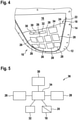
Figure 4 depicts the exterior aircraftlight cover 10, shown inFigure 3 , from the opposite side, i.e. from the side facing the outside of the aircraft, when the exterior aircraftlight cover 10 is mounted to anexterior aircraft light 2 / to an aircraft 100 (cf.Figure 2 ). -
Figure 4 shows a plurality ofelectric components inclined plane 24 of thehood 22 facing thelight transmissive pane 16. - The
electric components hood 22 include at least onephotovoltaic device photovoltaic devices photovoltaic device light sources exterior aircraft light 2 and reflected, in particular due to Fresnel reflections, by thelight transmissive pane 16 towards the at least onephotovoltaic device - It is noted that for simplicity, the
hood 22 and theelectric components Figure 2 . -
Figure 5 shows a block diagram of an electric circuit 33, comprising theelectric components light cover 10. - The plurality of
photovoltaic devices photovoltaic device 26, which is arranged at locations predominantly illuminated by light emitted by thelanding light sources 4, and at least one secondphotovoltaic device 28, which is arranged at locations predominantly illuminated by light emitted by the take-off light sources 6. - The
electric components hood 22, further comprise at least oneelectric storage device 30, for example at least onesupercapacitor 30. The at least oneelectric storage device 30 is configured for storing at least a portion of the electric energy generated by the at least onephotovoltaic device light source light source electric storage device 30 may in particular be configured to allow operating the at least one ancillarylight source light cover 10 for up to two hours, without the at least onephotovoltaic device - The
electric components controller 34, configured for switching and/or dimming the at least one ancillarylight source - The
controller 34 is electrically coupled to thephotovoltaic devices electric storage device 30, the at least one ancillarylight source sensor 32. - The
controller 34 is configured for controlling the flow of electric energy between thephotovoltaic devices electric storage device 30 and the at least one ancillarylight source - The
sensor 32 may comprise a variometer and/or an accelerometer, which is configured for detecting the height and/or the acceleration of theaircraft 100. - The
sensor 32 and thecontroller 34 are operated with electric energy supplied by thephotovoltaic devices electric storage device 30 as well. - In the embodiment depicted in
Figure 4 , theelectric storage devices 30, thesensor 32 and thecontroller 34 are arranged on the side of theinclined plane 24 facing thelight transmissive pane 16. Theelectric storage devices 30, thesensor 32 and/or thecontroller 34 may alternatively be mounted to the opposite side of theinclined plane 24, i.e. the side facing away from thelight transmissive pane 16. - An exterior aircraft
light cover 10 according to an exemplary embodiment, as it is depicted inFigures 2 to 5 , is an exterior aircraftlight cover 10 that allows for providing additional illumination of anexterior aircraft light 2. - The exterior aircraft
light cover 10 is in particular operable, without establishing any electric connections between the exterior aircraftlight cover 10 and the electric system of theaircraft 100. In consequence, a conventional transparent pane, covering the light sources of a conventional exterior aircraft light, may be replaced easily by an exterior aircraftlight cover 10 according to an exemplary embodiment of the invention, without intervening with the electric system of theaircraft 100. As an exterior aircraftlight cover 10 according to an exemplary embodiment of the invention does not intervene with the electric system of theaircraft 100, the process of certifying such an exterior aircraftlight cover 10 for use in commercial aircraft is considerably simplified. - In the following, different possible modes of operating an exterior aircraft
light cover 10 according to exemplary embodiments of the invention are described. In an exterior aircraftlight cover 10 according to exemplary embodiments of the invention, one or more of these modes may be implemented. - For example, it may be desirable that the ancillary
light sources light cover 10 are switched on, when theaircraft 100 is approaching an airport, landing, and/or taxiing at said airport, and it may be desirable that the ancillarylight sources light cover 10 are switched off for take-off. - According to an exemplary embodiment of the invention, an automatic switching of the ancillary
light sources controller 34 to evaluate signals provided by asensor 32. Saidsensor 32 may in particular include a variometer and/or an accelerometer. - Based on a sensor signal provided by a variometer, the
controller 34 is capable to determine whether theaircraft 100 is descending for landing and to switch on the ancillarylight sources light cover 10, when such a landing situation is detected. - From the signals provided by a variometer, the
controller 34 is further capable to determine whether theaircraft 100 is ascending during take-off and to switch on the ancillarylight sources - Alternatively or additionally, an accelerometer may be used for detecting whether the aircraft is in a take-off situation or in a landing situation.
- For example, a sensor signal from an accelerometer, corresponding to a strong acceleration that extends at least over a predetermined amount of time, indicates that the
aircraft 100 is taking-off, and a sensor signal, corresponding to a deceleration that extends at least over a predetermined amount of time, indicates that theaircraft 100 is in a landing approach. - Switching the ancillary
light sources light cover 10 based on signals provided by such asensor 32 allows for a reliable switching of the ancillarylight sources exterior aircraft light 2, to which the exterior aircraftlight cover 10 is mounted, does not indicate whether theaircraft 100 is currently taking-off or landing. - When the mode of operation of the
exterior aircraft light 2 indicates whether theaircraft 100 is currently taking-off or landing, the light emitted by the targetedlight sources exterior aircraft light 2 may be used as an indicator for determining whether the the ancillarylight sources light cover 10 are to be switched on or off. - In the following, a method of using the light emitted by the targeted
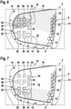
light sources exterior aircraft light 2 as an indicator for determining whether the ancillarylight sources light cover 10 are to be switched on or off is described with reference toFigures 6 and 7. Figures 6 and 7 show theexterior aircraft light 2, depicted inFigure 2 , in different operational states. -
Figure 6 illustrates the operation of theexterior aircraft light 2 in a landing situation, in which thelanding light sources 4 are switched on, and the take-off light sources 6 are switched off.Figure 6 shows that in a landing situation, in which thelanding light sources 4 are switched on, more light is reflected by thelight transmissive pane 16 onto the firstphotovoltaic device 26 than onto the secondphotovoltaic device 28. -
Figure 7 illustrates the operation of theexterior aircraft light 2 during take-off. During take-off, thelanding light sources 4 are switched off, and the take-off light sources 6 are switched on.Figure 7 shows that during take-off, when the take-off light sources 6 are switched on, more light is reflected by thelight transmissive pane 16 onto the secondphotovoltaic device 28 than onto the firstphotovoltaic device 26. - In a configuration as it is depicted in
Figures 6 and 7 , thephotovoltaic devices light cover 10. Thephotovoltaic devices landing light sources 4 and the take-off light sources 6, respectively. As thelanding light sources 4 and the take-off light sources 6 are not switched on simultaneously, detecting the operational states of thelanding light sources 4 and the take-off light sources 6 may in particular include comparing the energies / voltages, supplied by the first and secondphotovoltaic devices - By comparing the electric energies / voltages, supplied by the first and second
photovoltaic devices controller 34 may determine that only thelanding light sources 4 are switched on. This indicates that theaircraft 100 is currently in a landing approach. In consequence, thecontroller 34 activates the ancillarylight sources light cover 10. - Similarly, by comparing the energies / voltages, supplied by the first and second
photovoltaic devices controller 34 may determine that only the take-off light sources 6 are switched on. This indicates that theaircraft 100 is preparing for take-off. In consequence, the ancillarylight sources light cover 10 are switched off by thecontroller 34. - In an embodiment, in which the ancillary
light sources light cover 10 are switched on and off based on detected light, emitted by thelanding light sources 4 and the take-off light sources 6 of theexterior aircraft light 2 and then reflected by thelight transmissive pane 16 towards thephotovoltaic devices additional sensor 32, such as a variometer or an accelerometer, may be saved. This may allow for reducing the complexity and/or cost of the exterior aircraftlight cover 10. - While the invention has been described with reference to exemplary embodiments, it will be understood by those skilled in the art that various changes may be made and equivalence may be substituted for elements thereof without departing from the scope of the invention. In addition, many modifications may be made to adapt a particular situation or material to the teaching of the invention without departing from the essential scope thereof. Therefore, it is intended that the invention not be limited to the particular embodiments disclosed, but that the invention will include all embodiments falling within the scope of the appended claims.
Claims (15)
- Exterior aircraft light cover (10) with integrated illumination, comprising:a mounting portion (12), configured to be mounted to an exterior aircraft light housing (3);a light transmissive pane (16), supported by the mounting portion (12), wherein the mounting portion (12) and the light transmissive pane (16) are configured to jointly close the exterior aircraft light housing (3);at least one photovoltaic device (26, 28), which is configured for generating electric energy when illuminated;at least one electric storage device (30), which is configured for storing at least a portion of the electric energy generated by the at least one photovoltaic device (26, 28); andat least one ancillary light source (18, 20), which is operable with electric energy supplied by at least one of the at least one photovoltaic device (26, 28) and the at least one electric storage device (30).
- Exterior aircraft light cover (10) according to claim 1, wherein the exterior aircraft light housing (3) is a dedicated component or a recess formed in a body of an aircraft (100).
- Exterior aircraft light cover (10) according to claim 1 or 2, further comprising a controller (34) configured for switching and/or dimming the at least one ancillary light source (18, 20), wherein the controller (34) is in particular configured for switching and/or dimming the at least one ancillary light source (18, 20) in response to a sensor signal received by the controller (34).
- Exterior aircraft light cover (10) according to claim 3, further comprising a sensor (32), in particular a light sensor, a variometer or an accelerometer, configured for supplying a sensor signal to the controller (34).
- Exterior aircraft light cover (10) according to claim 3 or 4, comprising at least one first photovoltaic device (26) and at least one second photovoltaic device (28), wherein the controller (34) is configured for switching and/or dimming the at least one ancillary light source (18, 20) in response to the electric power provided by the at least one first photovoltaic device (26) and the at least one second photovoltaic device (28), in particular in response to a difference between the electric power provided by the at least one first photovoltaic device (26) and the at least one second photovoltaic device (28).
- Exterior aircraft light cover (10) according to claim 5, wherein the controller (34) is configured for switching the at least one ancillary light source (18, 20) on if the at least one first photovoltaic device (26) provides more electric power than the at least one second photovoltaic device (28), and/or wherein the controller (34) is configured for switching the at least one ancillary light source (18, 20) off if the at least one first photovoltaic device (26) provides less electric power than the at least one second photovoltaic device (28).
- Exterior aircraft light cover (10) according to any of the preceding claims, wherein the at least one ancillary light source (18, 20) is supported by at least one of the mounting portion (12) and the light transmissive pane (16).
- Exterior aircraft light cover (10) according to any of the preceding claims, wherein the at least one ancillary light source (18, 20) is arranged at a periphery of the light transmissive pane (16), wherein the at least one ancillary light source (18, 20) in particular includes a light strip that extends at least along a portion of the periphery of the light transmissive pane (16).
- Exterior aircraft light cover (10) according to any of the preceding claims, further comprising a support structure (22), supporting at least one of the at least one photovoltaic device (26, 28), the at least one electric storage device (30) and the controller (34).
- Exterior aircraft light cover (10) according to claim 9, wherein the support structure (22) includes a hood (22) extending over a portion of the light transmissive pane (16), wherein the hood (22) is in particular spaced apart from the light transmissive pane (16).
- Exterior aircraft light cover (10) according to any of the preceding claims, wherein the at least one electric storage device (30) includes at least one supercapacitor.
- Exterior aircraft light (2), comprising:an exterior aircraft light housing (3);at least one targeted light source (4, 6), supported by the exterior aircraft light housing (3);and an exterior aircraft light cover (10) according to any of the preceding claims.
- Exterior aircraft light according to claim 12, wherein the exterior aircraft light (2) is configured to selectively operate as a landing light or as a take-off light, wherein the exterior aircraft light cover (10) is configured to detect at least a portion of the light emitted by the exterior aircraft light (2) in order to switch on the at least one ancillary light source (18, 20) when the exterior aircraft light is operating as a landing light, and to switch off the at least one ancillary light source (18, 20) when the exterior aircraft light (2) is operating as a take-off light.
- Aircraft (100), such as an air plane, comprising at least one exterior aircraft light (2) according to claim 12 or 13.
- Method of upgrading or maintaining an exterior aircraft light (2) comprising an exterior aircraft light cover (10) having a light transmissive pane (16), wherein the method includes:removing the exterior aircraft light cover (10) from the exterior aircraft light (2); andmounting an exterior aircraft light cover (10) according to any of claims 1 to 11 to the exterior aircraft light (2).
Priority Applications (2)
| Application Number | Priority Date | Filing Date | Title |
|---|---|---|---|
| EP20186576.3A EP3939894B1 (en) | 2020-07-17 | 2020-07-17 | Exterior aircraft light cover, exterior aircraft light comprising the same, and method of upgrading or maintaining an exterior aircraft light |
| US17/376,214 US11565828B2 (en) | 2020-07-17 | 2021-07-15 | Exterior aircraft light cover, exterior aircraft light comprising the same, and method of upgrading or maintaining an exterior aircraft light |
Applications Claiming Priority (1)
| Application Number | Priority Date | Filing Date | Title |
|---|---|---|---|
| EP20186576.3A EP3939894B1 (en) | 2020-07-17 | 2020-07-17 | Exterior aircraft light cover, exterior aircraft light comprising the same, and method of upgrading or maintaining an exterior aircraft light |
Publications (2)
| Publication Number | Publication Date |
|---|---|
| EP3939894A1 true EP3939894A1 (en) | 2022-01-19 |
| EP3939894B1 EP3939894B1 (en) | 2023-12-27 |
Family
ID=71670178
Family Applications (1)
| Application Number | Title | Priority Date | Filing Date |
|---|---|---|---|
| EP20186576.3A Active EP3939894B1 (en) | 2020-07-17 | 2020-07-17 | Exterior aircraft light cover, exterior aircraft light comprising the same, and method of upgrading or maintaining an exterior aircraft light |
Country Status (2)
| Country | Link |
|---|---|
| US (1) | US11565828B2 (en) |
| EP (1) | EP3939894B1 (en) |
Cited By (1)
| Publication number | Priority date | Publication date | Assignee | Title |
|---|---|---|---|---|
| EP4324751A1 (en) * | 2022-08-18 | 2024-02-21 | Goodrich Lighting Systems GmbH & Co. KG | Protective cover for a fuselage-mounted exterior aircraft light and exterior aircraft light |
Families Citing this family (2)
| Publication number | Priority date | Publication date | Assignee | Title |
|---|---|---|---|---|
| JP7462635B2 (en) * | 2019-07-12 | 2024-04-05 | 株式会社小糸製作所 | Aircraft Lighting |
| EP4570667A1 (en) | 2023-12-15 | 2025-06-18 | Goodrich Lighting Systems GmbH & Co. KG | Aircraft headlight and aircraft comprising an aircraft headlight |
Citations (3)
| Publication number | Priority date | Publication date | Assignee | Title |
|---|---|---|---|---|
| US6637916B2 (en) * | 2000-10-05 | 2003-10-28 | Muellner Hermann-Frank | Lamp for vehicles |
| US20120201041A1 (en) * | 2006-02-22 | 2012-08-09 | Federal Signal Corporation | Self-powered light bar |
| US10253466B2 (en) * | 2014-07-28 | 2019-04-09 | Cyclops Road Studs Limited | Ground level illumination system |
Family Cites Families (5)
| Publication number | Priority date | Publication date | Assignee | Title |
|---|---|---|---|---|
| US6431728B1 (en) * | 2000-07-05 | 2002-08-13 | Whelen Engineering Company, Inc. | Multi-array LED warning lights |
| US9010959B2 (en) | 2011-08-08 | 2015-04-21 | Borealis Technical Limited | System and method for generating artificial light |
| EP3141485B1 (en) | 2015-09-10 | 2019-10-30 | Goodrich Lighting Systems GmbH | Dynamic exterior aircraft light unit and method of operating a dynamic exterior aircraft light unit |
| EP3168160B1 (en) | 2015-11-13 | 2018-07-11 | Goodrich Lighting Systems GmbH | Exterior aircraft light unit and aircraft comprising the same |
| US20190241278A1 (en) * | 2016-07-01 | 2019-08-08 | Maurice A. Khawam | Helicopter and window lights |
-
2020
- 2020-07-17 EP EP20186576.3A patent/EP3939894B1/en active Active
-
2021
- 2021-07-15 US US17/376,214 patent/US11565828B2/en active Active
Patent Citations (3)
| Publication number | Priority date | Publication date | Assignee | Title |
|---|---|---|---|---|
| US6637916B2 (en) * | 2000-10-05 | 2003-10-28 | Muellner Hermann-Frank | Lamp for vehicles |
| US20120201041A1 (en) * | 2006-02-22 | 2012-08-09 | Federal Signal Corporation | Self-powered light bar |
| US10253466B2 (en) * | 2014-07-28 | 2019-04-09 | Cyclops Road Studs Limited | Ground level illumination system |
Cited By (3)
| Publication number | Priority date | Publication date | Assignee | Title |
|---|---|---|---|---|
| EP4324751A1 (en) * | 2022-08-18 | 2024-02-21 | Goodrich Lighting Systems GmbH & Co. KG | Protective cover for a fuselage-mounted exterior aircraft light and exterior aircraft light |
| US20240060626A1 (en) * | 2022-08-18 | 2024-02-22 | Goodrich Lighting Systems GmbH & Co. KG | Protective cover for a fuselage-mounted exterior aircraft light and exterior aircraft light |
| US12072078B2 (en) * | 2022-08-18 | 2024-08-27 | Goodrich Lighting Systems GmbH & Co. KG | Protective cover for a fuselage-mounted exterior aircraft light and exterior aircraft light |
Also Published As
| Publication number | Publication date |
|---|---|
| EP3939894B1 (en) | 2023-12-27 |
| US11565828B2 (en) | 2023-01-31 |
| US20220017236A1 (en) | 2022-01-20 |
Similar Documents
| Publication | Publication Date | Title |
|---|---|---|
| US11565828B2 (en) | Exterior aircraft light cover, exterior aircraft light comprising the same, and method of upgrading or maintaining an exterior aircraft light | |
| US10919644B2 (en) | Multi-mode aircraft navigation light and aircraft comprising the same | |
| CN107757936B (en) | Exterior aircraft light unit and method of alerting ground personnel | |
| US6461029B2 (en) | Led position lamp | |
| US9745961B2 (en) | Offshore wind farm illumination | |
| EP3072813B1 (en) | Helicopter light system with layer material arranged on a rotor blade tip of the helicopter and helicopter comprising the same | |
| EP3626631B1 (en) | Aircraft light for a foldable wing tip, aircraft comprising and method of operating such aircraft light | |
| EP3584171A1 (en) | Aircraft beacon light and aircraft comprising an aircraft beacon light | |
| EP3572333B1 (en) | Aircraft light and aircraft light assembly | |
| EP3812283B1 (en) | Exterior aircraft image projector | |
| US10836506B2 (en) | Exterior aircraft light, aircraft wing comprising the same, and method of operating an exterior aircraft light | |
| US10750589B2 (en) | Exterior aircraft light unit and aircraft comprising the same | |
| KR100961104B1 (en) | Car lighting | |
| WO2006042052A2 (en) | Multicolored led vehicle interior light | |
| US12128833B2 (en) | Light assembly for motor vehicle | |
| EP4620832A1 (en) | Exterior aircraft light, aircraft comprising the same, and method for checking the operation of an exterior aircraft light | |
| EP4477559B1 (en) | Exterior aircraft light, aircraft comprising an exterior aircraft light and method of draining a fluid out of an exterior aircraft light | |
| EP4509411A1 (en) | Aircraft light, aircraft comprising an aircraft light, and method of assembling an aircraft light | |
| US12449116B2 (en) | Aircraft light, aircraft comprising an aircraft light, method of assembling an aircraft light, and method of manufacturing a sensor cap for an aircraft light | |
| EP4339105B1 (en) | Aircraft beacon light, aircraft with an aircraft beacon light and method of operating an aircraft beacon light | |
| US11691757B2 (en) | Aircraft exterior lighting multi-emitter array for variable beam profile | |
| US12325534B2 (en) | Aircraft light, aircraft comprising an aircraft light, and method of manufacturing an aircraft light | |
| US20260049704A1 (en) | Aircraft tail navigation light, aircraft comprising an aircraft tail navigation light, and method of operating an aircraft tail navigation light | |
| EP4596422A1 (en) | Aircraft navigation light and aircraft comprising the same | |
| GB2406200A (en) | Improvements in or relating to onboard equipment for aircraft and the like |
Legal Events
| Date | Code | Title | Description |
|---|---|---|---|
| PUAI | Public reference made under article 153(3) epc to a published international application that has entered the european phase |
Free format text: ORIGINAL CODE: 0009012 |
|
| STAA | Information on the status of an ep patent application or granted ep patent |
Free format text: STATUS: THE APPLICATION HAS BEEN PUBLISHED |
|
| AK | Designated contracting states |
Kind code of ref document: A1 Designated state(s): AL AT BE BG CH CY CZ DE DK EE ES FI FR GB GR HR HU IE IS IT LI LT LU LV MC MK MT NL NO PL PT RO RS SE SI SK SM TR |
|
| STAA | Information on the status of an ep patent application or granted ep patent |
Free format text: STATUS: REQUEST FOR EXAMINATION WAS MADE |
|
| 17P | Request for examination filed |
Effective date: 20220718 |
|
| RBV | Designated contracting states (corrected) |
Designated state(s): AL AT BE BG CH CY CZ DE DK EE ES FI FR GB GR HR HU IE IS IT LI LT LU LV MC MK MT NL NO PL PT RO RS SE SI SK SM TR |
|
| GRAP | Despatch of communication of intention to grant a patent |
Free format text: ORIGINAL CODE: EPIDOSNIGR1 |
|
| STAA | Information on the status of an ep patent application or granted ep patent |
Free format text: STATUS: GRANT OF PATENT IS INTENDED |
|
| INTG | Intention to grant announced |
Effective date: 20230713 |
|
| GRAS | Grant fee paid |
Free format text: ORIGINAL CODE: EPIDOSNIGR3 |
|
| GRAA | (expected) grant |
Free format text: ORIGINAL CODE: 0009210 |
|
| STAA | Information on the status of an ep patent application or granted ep patent |
Free format text: STATUS: THE PATENT HAS BEEN GRANTED |
|
| AK | Designated contracting states |
Kind code of ref document: B1 Designated state(s): AL AT BE BG CH CY CZ DE DK EE ES FI FR GB GR HR HU IE IS IT LI LT LU LV MC MK MT NL NO PL PT RO RS SE SI SK SM TR |
|
| REG | Reference to a national code |
Ref country code: GB Ref legal event code: FG4D |
|
| REG | Reference to a national code |
Ref country code: CH Ref legal event code: EP |
|
| REG | Reference to a national code |
Ref country code: DE Ref legal event code: R096 Ref document number: 602020023289 Country of ref document: DE |
|
| REG | Reference to a national code |
Ref country code: IE Ref legal event code: FG4D |
|
| PG25 | Lapsed in a contracting state [announced via postgrant information from national office to epo] |
Ref country code: GR Free format text: LAPSE BECAUSE OF FAILURE TO SUBMIT A TRANSLATION OF THE DESCRIPTION OR TO PAY THE FEE WITHIN THE PRESCRIBED TIME-LIMIT Effective date: 20240328 |
|
| REG | Reference to a national code |
Ref country code: LT Ref legal event code: MG9D |
|
| PG25 | Lapsed in a contracting state [announced via postgrant information from national office to epo] |
Ref country code: LT Free format text: LAPSE BECAUSE OF FAILURE TO SUBMIT A TRANSLATION OF THE DESCRIPTION OR TO PAY THE FEE WITHIN THE PRESCRIBED TIME-LIMIT Effective date: 20231227 |
|
| PG25 | Lapsed in a contracting state [announced via postgrant information from national office to epo] |
Ref country code: ES Free format text: LAPSE BECAUSE OF FAILURE TO SUBMIT A TRANSLATION OF THE DESCRIPTION OR TO PAY THE FEE WITHIN THE PRESCRIBED TIME-LIMIT Effective date: 20231227 |
|
| PG25 | Lapsed in a contracting state [announced via postgrant information from national office to epo] |
Ref country code: LT Free format text: LAPSE BECAUSE OF FAILURE TO SUBMIT A TRANSLATION OF THE DESCRIPTION OR TO PAY THE FEE WITHIN THE PRESCRIBED TIME-LIMIT Effective date: 20231227 Ref country code: GR Free format text: LAPSE BECAUSE OF FAILURE TO SUBMIT A TRANSLATION OF THE DESCRIPTION OR TO PAY THE FEE WITHIN THE PRESCRIBED TIME-LIMIT Effective date: 20240328 Ref country code: FI Free format text: LAPSE BECAUSE OF FAILURE TO SUBMIT A TRANSLATION OF THE DESCRIPTION OR TO PAY THE FEE WITHIN THE PRESCRIBED TIME-LIMIT Effective date: 20231227 Ref country code: ES Free format text: LAPSE BECAUSE OF FAILURE TO SUBMIT A TRANSLATION OF THE DESCRIPTION OR TO PAY THE FEE WITHIN THE PRESCRIBED TIME-LIMIT Effective date: 20231227 Ref country code: BG Free format text: LAPSE BECAUSE OF FAILURE TO SUBMIT A TRANSLATION OF THE DESCRIPTION OR TO PAY THE FEE WITHIN THE PRESCRIBED TIME-LIMIT Effective date: 20240327 |
|
| REG | Reference to a national code |
Ref country code: NL Ref legal event code: MP Effective date: 20231227 |
|
| REG | Reference to a national code |
Ref country code: AT Ref legal event code: MK05 Ref document number: 1644318 Country of ref document: AT Kind code of ref document: T Effective date: 20231227 |
|
| PG25 | Lapsed in a contracting state [announced via postgrant information from national office to epo] |
Ref country code: NL Free format text: LAPSE BECAUSE OF FAILURE TO SUBMIT A TRANSLATION OF THE DESCRIPTION OR TO PAY THE FEE WITHIN THE PRESCRIBED TIME-LIMIT Effective date: 20231227 |
|
| PG25 | Lapsed in a contracting state [announced via postgrant information from national office to epo] |
Ref country code: SE Free format text: LAPSE BECAUSE OF FAILURE TO SUBMIT A TRANSLATION OF THE DESCRIPTION OR TO PAY THE FEE WITHIN THE PRESCRIBED TIME-LIMIT Effective date: 20231227 Ref country code: RS Free format text: LAPSE BECAUSE OF FAILURE TO SUBMIT A TRANSLATION OF THE DESCRIPTION OR TO PAY THE FEE WITHIN THE PRESCRIBED TIME-LIMIT Effective date: 20231227 Ref country code: NO Free format text: LAPSE BECAUSE OF FAILURE TO SUBMIT A TRANSLATION OF THE DESCRIPTION OR TO PAY THE FEE WITHIN THE PRESCRIBED TIME-LIMIT Effective date: 20240327 Ref country code: NL Free format text: LAPSE BECAUSE OF FAILURE TO SUBMIT A TRANSLATION OF THE DESCRIPTION OR TO PAY THE FEE WITHIN THE PRESCRIBED TIME-LIMIT Effective date: 20231227 Ref country code: LV Free format text: LAPSE BECAUSE OF FAILURE TO SUBMIT A TRANSLATION OF THE DESCRIPTION OR TO PAY THE FEE WITHIN THE PRESCRIBED TIME-LIMIT Effective date: 20231227 Ref country code: HR Free format text: LAPSE BECAUSE OF FAILURE TO SUBMIT A TRANSLATION OF THE DESCRIPTION OR TO PAY THE FEE WITHIN THE PRESCRIBED TIME-LIMIT Effective date: 20231227 |
|
| PG25 | Lapsed in a contracting state [announced via postgrant information from national office to epo] |
Ref country code: IS Free format text: LAPSE BECAUSE OF FAILURE TO SUBMIT A TRANSLATION OF THE DESCRIPTION OR TO PAY THE FEE WITHIN THE PRESCRIBED TIME-LIMIT Effective date: 20240427 |
|
| PG25 | Lapsed in a contracting state [announced via postgrant information from national office to epo] |
Ref country code: CZ Free format text: LAPSE BECAUSE OF FAILURE TO SUBMIT A TRANSLATION OF THE DESCRIPTION OR TO PAY THE FEE WITHIN THE PRESCRIBED TIME-LIMIT Effective date: 20231227 Ref country code: AT Free format text: LAPSE BECAUSE OF FAILURE TO SUBMIT A TRANSLATION OF THE DESCRIPTION OR TO PAY THE FEE WITHIN THE PRESCRIBED TIME-LIMIT Effective date: 20231227 |
|
| PG25 | Lapsed in a contracting state [announced via postgrant information from national office to epo] |
Ref country code: SK Free format text: LAPSE BECAUSE OF FAILURE TO SUBMIT A TRANSLATION OF THE DESCRIPTION OR TO PAY THE FEE WITHIN THE PRESCRIBED TIME-LIMIT Effective date: 20231227 |
|
| PG25 | Lapsed in a contracting state [announced via postgrant information from national office to epo] |
Ref country code: SM Free format text: LAPSE BECAUSE OF FAILURE TO SUBMIT A TRANSLATION OF THE DESCRIPTION OR TO PAY THE FEE WITHIN THE PRESCRIBED TIME-LIMIT Effective date: 20231227 Ref country code: SK Free format text: LAPSE BECAUSE OF FAILURE TO SUBMIT A TRANSLATION OF THE DESCRIPTION OR TO PAY THE FEE WITHIN THE PRESCRIBED TIME-LIMIT Effective date: 20231227 Ref country code: RO Free format text: LAPSE BECAUSE OF FAILURE TO SUBMIT A TRANSLATION OF THE DESCRIPTION OR TO PAY THE FEE WITHIN THE PRESCRIBED TIME-LIMIT Effective date: 20231227 Ref country code: IT Free format text: LAPSE BECAUSE OF FAILURE TO SUBMIT A TRANSLATION OF THE DESCRIPTION OR TO PAY THE FEE WITHIN THE PRESCRIBED TIME-LIMIT Effective date: 20231227 Ref country code: IS Free format text: LAPSE BECAUSE OF FAILURE TO SUBMIT A TRANSLATION OF THE DESCRIPTION OR TO PAY THE FEE WITHIN THE PRESCRIBED TIME-LIMIT Effective date: 20240427 Ref country code: EE Free format text: LAPSE BECAUSE OF FAILURE TO SUBMIT A TRANSLATION OF THE DESCRIPTION OR TO PAY THE FEE WITHIN THE PRESCRIBED TIME-LIMIT Effective date: 20231227 Ref country code: CZ Free format text: LAPSE BECAUSE OF FAILURE TO SUBMIT A TRANSLATION OF THE DESCRIPTION OR TO PAY THE FEE WITHIN THE PRESCRIBED TIME-LIMIT Effective date: 20231227 Ref country code: AT Free format text: LAPSE BECAUSE OF FAILURE TO SUBMIT A TRANSLATION OF THE DESCRIPTION OR TO PAY THE FEE WITHIN THE PRESCRIBED TIME-LIMIT Effective date: 20231227 |
|
| PG25 | Lapsed in a contracting state [announced via postgrant information from national office to epo] |
Ref country code: PL Free format text: LAPSE BECAUSE OF FAILURE TO SUBMIT A TRANSLATION OF THE DESCRIPTION OR TO PAY THE FEE WITHIN THE PRESCRIBED TIME-LIMIT Effective date: 20231227 Ref country code: PT Free format text: LAPSE BECAUSE OF FAILURE TO SUBMIT A TRANSLATION OF THE DESCRIPTION OR TO PAY THE FEE WITHIN THE PRESCRIBED TIME-LIMIT Effective date: 20240429 |
|
| PG25 | Lapsed in a contracting state [announced via postgrant information from national office to epo] |
Ref country code: PT Free format text: LAPSE BECAUSE OF FAILURE TO SUBMIT A TRANSLATION OF THE DESCRIPTION OR TO PAY THE FEE WITHIN THE PRESCRIBED TIME-LIMIT Effective date: 20240429 Ref country code: PL Free format text: LAPSE BECAUSE OF FAILURE TO SUBMIT A TRANSLATION OF THE DESCRIPTION OR TO PAY THE FEE WITHIN THE PRESCRIBED TIME-LIMIT Effective date: 20231227 |
|
| REG | Reference to a national code |
Ref country code: DE Ref legal event code: R097 Ref document number: 602020023289 Country of ref document: DE |
|
| PG25 | Lapsed in a contracting state [announced via postgrant information from national office to epo] |
Ref country code: DK Free format text: LAPSE BECAUSE OF FAILURE TO SUBMIT A TRANSLATION OF THE DESCRIPTION OR TO PAY THE FEE WITHIN THE PRESCRIBED TIME-LIMIT Effective date: 20231227 |
|
| PG25 | Lapsed in a contracting state [announced via postgrant information from national office to epo] |
Ref country code: DK Free format text: LAPSE BECAUSE OF FAILURE TO SUBMIT A TRANSLATION OF THE DESCRIPTION OR TO PAY THE FEE WITHIN THE PRESCRIBED TIME-LIMIT Effective date: 20231227 |
|
| PLBE | No opposition filed within time limit |
Free format text: ORIGINAL CODE: 0009261 |
|
| STAA | Information on the status of an ep patent application or granted ep patent |
Free format text: STATUS: NO OPPOSITION FILED WITHIN TIME LIMIT |
|
| 26N | No opposition filed |
Effective date: 20240930 |
|
| PG25 | Lapsed in a contracting state [announced via postgrant information from national office to epo] |
Ref country code: MC Free format text: LAPSE BECAUSE OF FAILURE TO SUBMIT A TRANSLATION OF THE DESCRIPTION OR TO PAY THE FEE WITHIN THE PRESCRIBED TIME-LIMIT Effective date: 20231227 |
|
| REG | Reference to a national code |
Ref country code: CH Ref legal event code: PL |
|
| PG25 | Lapsed in a contracting state [announced via postgrant information from national office to epo] |
Ref country code: LU Free format text: LAPSE BECAUSE OF NON-PAYMENT OF DUE FEES Effective date: 20240717 |
|
| PG25 | Lapsed in a contracting state [announced via postgrant information from national office to epo] |
Ref country code: LU Free format text: LAPSE BECAUSE OF NON-PAYMENT OF DUE FEES Effective date: 20240717 |
|
| PG25 | Lapsed in a contracting state [announced via postgrant information from national office to epo] |
Ref country code: SI Free format text: LAPSE BECAUSE OF FAILURE TO SUBMIT A TRANSLATION OF THE DESCRIPTION OR TO PAY THE FEE WITHIN THE PRESCRIBED TIME-LIMIT Effective date: 20231227 Ref country code: CH Free format text: LAPSE BECAUSE OF NON-PAYMENT OF DUE FEES Effective date: 20240731 Ref country code: BE Free format text: LAPSE BECAUSE OF NON-PAYMENT OF DUE FEES Effective date: 20240731 |
|
| REG | Reference to a national code |
Ref country code: BE Ref legal event code: MM Effective date: 20240731 |
|
| PG25 | Lapsed in a contracting state [announced via postgrant information from national office to epo] |
Ref country code: IE Free format text: LAPSE BECAUSE OF NON-PAYMENT OF DUE FEES Effective date: 20240717 |
|
| PGFP | Annual fee paid to national office [announced via postgrant information from national office to epo] |
Ref country code: DE Payment date: 20250620 Year of fee payment: 6 |
|
| PG25 | Lapsed in a contracting state [announced via postgrant information from national office to epo] |
Ref country code: CY Free format text: LAPSE BECAUSE OF FAILURE TO SUBMIT A TRANSLATION OF THE DESCRIPTION OR TO PAY THE FEE WITHIN THE PRESCRIBED TIME-LIMIT; INVALID AB INITIO Effective date: 20200717 |
|
| P01 | Opt-out of the competence of the unified patent court (upc) registered |
Free format text: CASE NUMBER: UPC_APP_0018748_3939894/2025 Effective date: 20251221 |
|
| PG25 | Lapsed in a contracting state [announced via postgrant information from national office to epo] |
Ref country code: HU Free format text: LAPSE BECAUSE OF FAILURE TO SUBMIT A TRANSLATION OF THE DESCRIPTION OR TO PAY THE FEE WITHIN THE PRESCRIBED TIME-LIMIT; INVALID AB INITIO Effective date: 20200717 |
|
| PG25 | Lapsed in a contracting state [announced via postgrant information from national office to epo] |
Ref country code: TR Free format text: LAPSE BECAUSE OF FAILURE TO SUBMIT A TRANSLATION OF THE DESCRIPTION OR TO PAY THE FEE WITHIN THE PRESCRIBED TIME-LIMIT Effective date: 20231227 |
|
| PGFP | Annual fee paid to national office [announced via postgrant information from national office to epo] |
Ref country code: GB Payment date: 20260618 Year of fee payment: 7 |
|
| PGFP | Annual fee paid to national office [announced via postgrant information from national office to epo] |
Ref country code: FR Payment date: 20260619 Year of fee payment: 7 |