EP3939709A1 - Vibration generation device - Google Patents
Vibration generation device Download PDFInfo
- Publication number
- EP3939709A1 EP3939709A1 EP20770919.7A EP20770919A EP3939709A1 EP 3939709 A1 EP3939709 A1 EP 3939709A1 EP 20770919 A EP20770919 A EP 20770919A EP 3939709 A1 EP3939709 A1 EP 3939709A1
- Authority
- EP
- European Patent Office
- Prior art keywords
- housing
- frequency
- region
- vibration
- vibrator
- Prior art date
- Legal status (The legal status is an assumption and is not a legal conclusion. Google has not performed a legal analysis and makes no representation as to the accuracy of the status listed.)
- Granted
Links
Images









Classifications
-
- B—PERFORMING OPERATIONS; TRANSPORTING
- B06—GENERATING OR TRANSMITTING MECHANICAL VIBRATIONS IN GENERAL
- B06B—METHODS OR APPARATUS FOR GENERATING OR TRANSMITTING MECHANICAL VIBRATIONS OF INFRASONIC, SONIC, OR ULTRASONIC FREQUENCY, e.g. FOR PERFORMING MECHANICAL WORK IN GENERAL
- B06B1/00—Methods or apparatus for generating mechanical vibrations of infrasonic, sonic, or ultrasonic frequency
- B06B1/02—Methods or apparatus for generating mechanical vibrations of infrasonic, sonic, or ultrasonic frequency making use of electrical energy
- B06B1/04—Methods or apparatus for generating mechanical vibrations of infrasonic, sonic, or ultrasonic frequency making use of electrical energy operating with electromagnetism
- B06B1/045—Methods or apparatus for generating mechanical vibrations of infrasonic, sonic, or ultrasonic frequency making use of electrical energy operating with electromagnetism using vibrating magnet, armature or coil system
-
- H—ELECTRICITY
- H04—ELECTRIC COMMUNICATION TECHNIQUE
- H04R—LOUDSPEAKERS, MICROPHONES, GRAMOPHONE PICK-UPS OR LIKE ACOUSTIC ELECTROMECHANICAL TRANSDUCERS; ELECTRIC HEARING AIDS; PUBLIC ADDRESS SYSTEMS
- H04R13/00—Transducers having an acoustic diaphragm of magnetisable material directly co-acting with electromagnet
-
- H—ELECTRICITY
- H04—ELECTRIC COMMUNICATION TECHNIQUE
- H04R—LOUDSPEAKERS, MICROPHONES, GRAMOPHONE PICK-UPS OR LIKE ACOUSTIC ELECTROMECHANICAL TRANSDUCERS; ELECTRIC HEARING AIDS; PUBLIC ADDRESS SYSTEMS
- H04R7/00—Diaphragms for electromechanical transducers; Cones
- H04R7/16—Mounting or tensioning of diaphragms or cones
-
- H—ELECTRICITY
- H04—ELECTRIC COMMUNICATION TECHNIQUE
- H04R—LOUDSPEAKERS, MICROPHONES, GRAMOPHONE PICK-UPS OR LIKE ACOUSTIC ELECTROMECHANICAL TRANSDUCERS; ELECTRIC HEARING AIDS; PUBLIC ADDRESS SYSTEMS
- H04R9/00—Transducers of moving-coil, moving-strip, or moving-wire type
- H04R9/02—Details
- H04R9/025—Magnetic circuit
Definitions
- the present disclosure relates to a vibration generating device.
- Patent Document 1 discloses a vibration source drive device that has an object to generate sound and vibration exclusively.
- Patent Document 1 Japanese Laid-Open Patent Application No. 2001-121079
- the present disclosure has an object to provide a vibration generating device capable of presenting sound and vibration that are sufficiently separated.
- a vibration generating device includes a housing; a diaphragm supported by the housing, and configured to generate sound by vibrating in a first direction; and a vibration providing part attached to the housing, and configured to vibrate the housing, wherein the vibration providing part vibrates the housing in the first direction at a first frequency, and vibrates the housing in a second direction at a second frequency lower than the first frequency.
- FIG. 1A , 1B , and 1C are diagram illustrating a configuration of a vibration generating device 200 according to a first embodiment.
- FIG. 1A is an exploded perspective view
- FIG. 1B is a plan view
- FIG. 1C is a cross-sectional view along a I-I line in FIG. 1B . Note that the directions in each figure are defined as X1 being left, X2 being right, Y1 being front, Y2 being rear, Z1 being upward, and Z2 being downward.
- the vibration generating device 200 has a lower case 210, a vibration providing part 220, an upper case 230, and a diaphragm 240.
- the lower case 210 and the upper case 230 are included in a housing 260.
- the lower case 210 has a disk-shaped bottom plate 211 and a cylinder-shaped side plate 212 extending upward from an edge of the bottom plate 211.
- the vibration providing part 220 is fixed to the top surface of the bottom plate 211 by a double-sided tape 251.
- the upper case 230 has a ring-shaped bottom plate 231 having an opening 232 formed at the center, and a guide part 233 provided at an edge of the bottom plate 231 to guide the diaphragm 240.
- the diaphragm 240 has a disk shape, and is fixed to the top surface of the bottom plate 231 by a ring-shaped double-sided tape 252 inside the guide part 233, to be held by the upper case 230.
- the upper case 230 is fixed to the lower case 210 so that the diaphragm 240 is positioned on the upside with respect to the upper case 230.
- the upper case 230 may be fixed to the lower case 210 so that the diaphragm 240 is positioned on the lower side with respect to the upper case 230.
- the upper case 230 is an example of a holder.
- the diaphragm 240 is supported by the housing 260, and generates sound by vibrating in a first direction (the Z1-Z2 direction).
- the vibration providing part 220 is attached to the housing 260, to vibrate the housing 260.
- the vibration providing part 220 vibrates the housing 260 in the first direction at the first frequency f1, and vibrates the housing 260 in a second direction at a second frequency f2 that is lower than the first frequency f1.
- the second direction is a direction different from the first direction, and favorably is a direction (the X1-X2 direction or the Y1-Y2 direction) orthogonal to the first direction (the Z1-Z2 direction).
- the diaphragm 240 can be integrally formed with the housing 260.
- the diaphragm 240 can be integrally formed with the upper case 230.
- the housing 260 and the diaphragm 240 are made of synthetic resin or made of metal.
- the housing 260 vibrating in the first direction causes the diaphragm 240 to vibrate in the first direction, and the diaphragm 240 vibrating the surrounding air generates sound.
- the first frequency f1 is not limited in particular, and may be set to be, for example, greater than or equal to 200 Hz and less than or equal to 6 kHz; in particular, it is favorable that the range is set to be, for example, greater than or equal to 1 kHz and less than or equal to 4 kHz that can be easily detected by the auditory perception of a person. Even if the housing 260 vibrates at a frequency in a range that can be easily detected by the auditory perception of a person, the vibration is hardly detected by the person through the tactile perception. Therefore, vibration at the first frequency f1 in the first direction can present sound to a person without causing the person to feel the vibration substantially.
- the second frequency f2 is not limited in particular, and may be set to be, for example, less than or equal to 600 Hz; in particular, it is favorable that the range is set to be, for example, greater than or equal to 100 Hz and less than or equal to 500 Hz that can be easily detected by the tactile perception of a person. Even in the case where the first frequency f1 is greater than or equal to 200 Hz and less than or equal to 600 Hz, the second frequency f2 simply needs to be lower than the first frequency f1.
- the auditory perception of a person can detect frequencies of sound that are easily detected by the tactile perception; however, when vibrating in the second direction, the diaphragm 240 hardly vibrates in the first direction, and thereby, the diaphragm 240 does not generate sound. Therefore, vibration at the second frequency f2 in the second direction can present vibration to a person without causing the person to feel sound substantially.
- FIGs. 2A and 2B are first explanatory diagrams illustrating a configuration of the vibration providing part 1.
- FIG. 2A is a perspective view illustrating an external appearance of the vibration providing part 1; and
- FIG. 2B is a perspective view illustrating the vibration providing part 1 in a state of a cover 12 being removed.
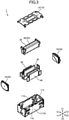
- FIG. 3 is a second explanatory diagram illustrating the configuration of the vibration providing part 1, and is an exploded perspective view of the vibration providing part 1.
- FIG. 4 is an explanatory diagram illustrating a configuration of the vibrator 20 in the vibration providing part 1, and is a perspective view of the vibrator 20.
- FIGs. 5A and 5B are first explanatory diagrams illustrating a configuration of the holder 30 and the elastic supporter 40 in the vibration providing part 1.
- FIG. 5A is a perspective view of the holder 30 and the elastic supporter 40; and
- FIG. 5B is a front view of the holder 30 and the elastic supporter 40 in the vibration providing part 1.
- FIGs. 6A and 6B are second explanatory diagrams illustrating a configuration of the holder 30 and the elastic supporter 40 in the vibration providing part 1.
- FIG. 6A is a side view in the case of viewing the holder 30 and the elastic supporter 40 from the right; and
- FIG. 6B is a cross-sectional view corresponding to a cross section of FIG. 5B along a cross section A1-A1.
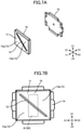
- FIG. 7A and 7B are explanatory diagrams illustrating a configuration of the permanent magnet in the vibration providing part 1.
- FIG. 7A is an exploded perspective view of the permanent magnet 70 on the rear side;
- FIG. 7B is a front view of the permanent magnet 70 on the rear side.
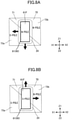
- FIGs. 8A and 8B are explanatory diagrams illustrating driving directions of the magnetic drive part 50 in the vibration providing part 1, in which the magnetic core 61 is viewed from the front.
- FIG. 8A illustrates a direction of a magnetic force exerted by the permanent magnet 70 on the front edge 61F of the core 61 when the front edge 61F of the core 61 is magnetized to be an N pole; and
- FIG. 8B illustrates a direction of a magnetic force exerted by the permanent magnet 70 on the front edge 61F of the core 61 when the front edge 61F of the core 61 is magnetized to be an S pole.
- a solid-line arrow indicates a direction of a magnetic force acting on the magnetic core 61.
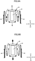
- FIGs. 9A and 9B are explanatory diagram illustrating vibration directions of the vibrator 20 in the vibration providing part 1, in which the vibrator 20, the holder 30, and the elastic supporter 40 are viewed from the front.
- FIG. 9A illustrates a vibration direction of the vibrator 20 when the electromagnet 60 generates an alternating magnetic field at the same frequency as the first natural frequency
- FIG. 9B illustrates a vibration direction of the vibrator 20 when the electromagnet 60 generates an alternating magnetic field at the same frequency as the second natural frequency.
- FIGs. 9A illustrates a vibration direction of the vibrator 20 when the electromagnet 60 generates an alternating magnetic field at the same frequency as the first natural frequency
- FIG. 9B illustrates a vibration direction of the vibrator 20 when the electromagnet 60 generates an alternating magnetic field at the same frequency as the second natural frequency.
- a solid-line arrow indicates a direction in which it is easier for the vibrator 20 to generate vibration, namely, the vibration direction of the vibrator 20, and a dashed-line arrow indicates a direction in which it is difficult for the vibrator 20 to generate vibration.
- the Z1-Z2 direction is an example of a first direction; the X1-X2 direction is an example of a second direction; and the Y1-Y2 direction is an example of a third direction.
- the vibration providing part 1 includes a housing 10, the vibrator 20, the holder 30, the two elastic supporters 40, and the magnetic drive part 50.
- the housing 10 is constituted by combining a main body 11 and the cover 12.
- the main body 11 is a box-like member having generally a rectangular shape formed by processing a metal plate, and has a container 11a as a recessed part that is generally a rectangular parallelepiped, and recessed downward from an upper end 11b of the main body 11.
- the cover 12 is a plate-like member having generally rectangular shape formed by processing a metal plate, and is attached to the upper end 11b of the main body 11 to cover the container 11a from the top.
- the housing 10 is an example of an inside housing.
- the vibrator 20 is a member having generally a rectangular shape contained in the container 11a of the housing 10.
- the electromagnet 60 as part of the magnetic drive part 50 is arranged.
- the holder 30 and the elastic supporter 40 are integrally formed by processing a metal plate having a spring property, to have a predetermined shape. As illustrated in FIG. 5A, 5B , 6A, and 6B , the holder 30 is a box-like part being generally a rectangular parallelepiped. As illustrated in FIG. 2B and 3 , in the holder 30, the lower part of the vibrator 20 is contained to be held.
- the elastic supporter 40 is a plate spring formed by folding a metal plate extending in the left-right direction multiple times so as to have the folds extend along the front-back direction.
- the two elastic supporters 40 one extends from the left end 30L of the holder 30 to the left side, and the other extends from the right end 30R of the holder 30 to the right side.
- the elastic supporter 40 extending from the left end 30L of the holder 30 to the left side will be referred to as the elastic supporter 40 on the left side; and the elastic supporter 40 extending from the right end 30R of the holder 30 to the right side will be referred to as the elastic supporter 40 on the right side.
- the elastic supporter 40 has three folded parts 41, two flat parts 42, and an attachment 43.
- the folded part 41 is a part at which the metal plate is folded along a folds.
- the flat part 42 is a part having generally a rectangular shape extending from one of the three folded parts 41 to another, and has sides along the direction of the folds and sides along the extending direction.
- the elastic supporter 40 is formed so as to make a dimension along the direction of the folds of the flat part 42 (referred to as the width dimension of the flat part 42, hereafter) greater than a dimension along the extending direction of the flat part 42 (referred to as the length dimension of the flat part 42, hereafter).
- an opening 42a having generally a rectangular shape is formed at a position away from the outer periphery of the flat part 42.
- a plate spring having such a folded structure as in the elastic supporter 40 has a feature in that elastic deformation occurs more easily in directions orthogonal to the folds (the left-right direction and the up-down direction). In other words, such a plate spring can be elastically deformed along the left-right direction due to expansion and contraction, and elastically deformed along the up-down direction by deflection. On the other hand, such a plate spring also has a feature in that deformation hardly occurs in the direction along the folds (in the front-back direction), and hence, is suitable as a member for suppressing movement along the front-back direction.
- the attachment 43 is formed at the tip of the elastic supporter 40.
- An engaging claw part 43a is formed at a predetermined position of the attachment 43. Further, by having of the engaging claw part 43a engaged with the main body 11 of the housing 10, the elastic supporter 40 is attached to the housing 10. Further, by elastic deformation along the left-right direction and along the up-down direction, the elastic supporter 40 supports the vibrator 20 to be capable of vibrating along the left-right direction and along the up-down direction.
- the vibrator 20 vibrates along the left-right direction at the first natural frequency that is determined according to the first modulus of elasticity and the mass of the vibrator 20, and vibrates along the up-down direction at the second natural frequency that is determined according to the second modulus of elasticity and the mass of the vibrator 20. Further, as the first modulus of elasticity and the second modulus of elasticity take different values from each other, the first natural frequency and the second natural frequency take different values from each other.
- the magnetic drive part 50 is configured to include the electromagnet 60 arranged facing the vibrator 20 (a first magnetic field generating part), and the two permanent magnets 70 arranged facing the housing 10 (a second magnetic field generating part).
- the electromagnet 60 has a magnetic core 61, a bobbin 62, a coil 63, and a terminal 64.
- the magnetic core 61 is a member having a prismatic shape made of a ferromagnetic material, and extends along the front-back direction.
- the bobbin 62 is a member having a cylindrical shape made of an insulator, and covers the outer periphery of the core 61.
- the coil 63 is formed by winding a wire around the outer periphery of the bobbin 62.
- the terminal 64 connects both ends of the coil 63 to an external circuit (not illustrated) via a member for wiring (not illustrated).
- the electromagnet 60 generates a magnetic field along the front-back direction by causing an alternating current to flow through the coil 63, to magnetize the front edge 61F and the rear edge 61R of the core 61 to have different poles. Further, by adopting an alternating current as the current flowing through the coil 63, the magnetic field generated by the electromagnet 60 is an alternating magnetic field in which the direction of the magnetic field changes in response to change in the direction of the current. Further, when the front edge 61F of the core 61 is serving as an S pole, the rear edge 61R is serving as an N pole, and when the front edge 61F of the core 61 is serving as an N pole, the rear edge 61R is serving as an S pole. The timing and the frequency of the alternating magnetic field generated by the electromagnet 60 are controlled by the external circuit described above.
- the permanent magnet 70 is a plate-like magnet being generally a rectangular parallelepiped.
- the two permanent magnets 70 are arranged on the front edge side and on the rear edge side of the housing 10, respectively, so as to be positioned on an extended line in the front-back direction of the magnetic core 61 included in the electromagnet 60 of the vibrator 20 (refer to as the extended line in the front-back direction of the vibrator 20, hereafter).
- the permanent magnet 70 has a magnetized face 71 that is formed to have generally a rectangular shape, and edges along the left-right direction and along the up-down direction. Further, the magnetized face 71 of the permanent magnet 70 is opposite to the magnetic core 61 of the electromagnet 60 in in the frond-back direction.
- the permanent magnet 70 has a slit 72 that is formed to extend diagonally from the upper left to the lower right of the magnetized face 71. Further, the magnetized face 71 is partitioned into two magnetized regions 73 by the slit 72, and the two magnetized regions 73 are magnetized to be magnetic poles different from each other. In this way, the permanent magnet 70 is magnetized to have different magnetic poles aligned along the left-right direction and along the up-down direction, respectively.
- the permanent magnet 70 arranged on the front edge side of the housing 10 will be referred to as the permanent magnet 70 on the front side; and the permanent magnet 70 arranged on the rear edge side of the housing 10 will be referred to as the permanent magnet 70 on the rear side.
- a region on the lower left side will be referred to as the first magnetized region 73a; and a region on the upper right side will be referred to as the second magnetized region 73b.
- the first magnetized region 73a becomes an S pole and the second magnetized region 73b becomes an N pole; and in the permanent magnet 70 on the rear side, the first magnetized region 73a becomes an N pole and the second magnetized region 73b becomes an S pole.
- a yoke 74 as a member made of a ferromagnetic material is attached to the permanent magnet 70, for directing the magnetic field generated by the permanent magnet 70 toward the electromagnet 60.
- the vibration providing part 1 has a configuration like this.
- the magnetic drive part 50 includes the electromagnet 60 arranged facing the vibrator 20, and the two permanent magnets 70 arranged facing the housing 10. Further, the electromagnet 60 generates an alternating magnetic field by causing an alternating current to flow through the coil 63, to magnetize the front edge 61F and the rear edge 61R of the core 61. Also, the permanent magnet 70 is arranged on the housing 10 side so to be opposite the electromagnet 60 in front and in the rear. Further, on the magnetized surface 71 of the permanent magnet 70, the first magnetized region 73a and the second magnetized region 73b that are magnetized to be different magnetic poles.
- the front edge 61F of the core 61 when the front edge 61F of the core 61 is magnetized to be an N pole, the front edge 61F of the core 61 attracts the first magnetized region 73a of the permanent magnet 70 on the front side to each other, and repels the second magnetized region 73b from each other.
- the rear edge 61R of the core 61 when the front edge 61F of the core 61 is magnetized to be an N pole, the rear edge 61R of the core 61 is magnetized to be an S pole; and the rear edge 61R of the core 61 attracts the first magnetized region 73a of the permanent magnet 70 on the rear side to each other, and repels the second magnetized region 73b from each other.
- the magnetic forces act on the vibrator 20 in the left direction and in the downward direction.
- the front edge 61F of the core 61 when the front edge 61F of the core 61 is magnetized to be an S pole, the front edge 61F of the core 61 repels the first magnetized region 73a of the permanent magnet 70 on the front side from each other, and attracts the second magnetized region 73b to each other.
- the rear edge 61R of the core 61 when the front edge 61F of the core 61 is magnetized to be an S pole, the rear edge 61R of the core 61 is magnetized to be an N pole; and the rear edge 61R of the magnetic core 61 repels the first magnetized region 73a of the permanent magnet 70 on the rear side from each other, and attracts the second magnetized region 73b to each other.
- the magnetic forces act on the vibrator 20 in the right direction and in the UP direction.
- the magnetic drive part 50 every time the direction of the magnetic field generated by the electromagnet 60 is inverted, the front edge 61F and the rear edge 61R of the magnetic core 61 of the electromagnet 60 attract or repel the first magnetized region 73a of the permanent magnet 70 to or from each other, and repel or attract the second magnetized region 73b from or to each other. Further, the magnetic drive part 50 uses the magnetic forces between the electromagnet 60 and the permanent magnet 70, to drive the vibrator 20 in the left-right direction and in the up-down direction.
- the vibrator 20 is supported by the elastic supporter 40, to be capable of vibrating along the left-right direction and along the up-down direction. Further, the vibrator 20 vibrates along the left-right direction at the first natural frequency that is determined according to the first modulus of elasticity and the mass of the vibrator 20, and vibrates along the up-down direction at the second natural frequency that is determined according to the second modulus of elasticity and the mass of the vibrator 20.
- the magnetic drive part 50 vibrates the vibrator 20 along the left-right direction by the alternating magnetic field at the same frequency as the first natural frequency, and vibrates the vibrator 20 along the up-down direction by the alternating magnetic field at the same frequency as the second natural frequency.
- vibrating the vibrator 20 along the left-right direction by the alternating magnetic field at the same frequency as the first natural frequency will be referred as to driving the vibrator 20 in the left-right direction at the first natural frequency; and vibrating the vibrator 20 along the up-down direction by the alternating magnetic field at the same frequency as the second natural frequency, will be referred as to driving the vibrator 20 in the up-down direction at the second natural frequency.
- a plate spring having such a folded structure like the elastic supporter 40 has a feature in that elastic deformation occurs easier in a direction orthogonal to the folds, whereas deformation hardly occurs in the direction along the folds. Therefore, in the vibration providing part 1, by using the feature of the plate spring, deformation of the elastic supporter 40 along the front-back direction is suppressed; and thereby, movement of the vibrator 20 along the front-back direction is suppressed, and vibrating operations of the vibrator 20 along the left-right direction and along the up-down direction are stabilized.
- a width dimension of the flat part 42 greater than the length dimension of the flat part 42 makes deformation along the folds more difficult.
- the elastic supporter 40 is formed so as to have the width dimension of the flat part 42 greater than the length dimension of the flat part 42, and thereby, deformation of the elastic supporter 40 along the front-back direction can be suppressed more easily.
- the outer periphery of the flat part 42 greatly influences the difficulty of deformation of the elastic supporter 40 along the folds
- the influence of part of the flat part 42 away from the outer periphery is smaller than the influence of the outer periphery of the flat part 42.
- the opening 42a at a part away from the outer periphery of the flat part 42, the mechanical strength in directions orthogonal to the folds of the flat part 42 (in the left-right direction and in the up-down direction) can be reduced, and thereby, the elastic supporter 40 can be made elastically deformable more easily in the directions orthogonal to the folds.
- the vibration providing part 1 is configured to have the opening 42a formed at a position away from the outer periphery of the flat part 42, so as to have elastic deformation occur easier along the left-right direction and along the up-down direction, while the deformability of the elastic supporter 40 along the front-back direction is suppressed. Further, by adjusting the dimensions of the opening 42a, the elastic deformability of the elastic supporter 40 along the left-right direction and along the up-down direction can be adjusted.
- the elastic supporter 40 is a plate spring formed to have the multiple folded parts 41 in which the folds are folded along the front-back direction (third direction) orthogonal to the left-right direction (first direction) and to the up-down direction (second direction), and the two flat parts 42 that have generally a rectangular shape and extend from one of the multiple folded parts 41 to another.
- a plate spring having such a folded structure has a feature in that elastic deformation occurs easier in a direction orthogonal to the folds, whereas deformation hardly occurs in the direction along the folds.
- the vibration providing part 1 by forming the opening 42a at a position away from the outer periphery of the flat part 42, while suppressing the deformability of the elastic supporter 40 along the front-back direction, elastic deformation can occur easier along the left-right direction and along the up-down direction. Further, by adjusting the dimensions of the opening 42a, the elastic deformability of the elastic supporter 40 along the left-right direction and along the up-down direction can be adjusted. As a result, while stabilizing the vibrating operations of the vibrator 20, the vibrator 20 can be easily vibrated along the left-right direction and along the up-down direction, and the easiness of vibration of the vibrator 20 can be adjusted.
- the vibration providing part 1 by forming the elastic supporter 40 so as to have the width dimension of the flat part 42 (the dimension in the direction along the folds)greater than the length dimension of the flat part 42 (the dimension along the extending direction), the deformation of the elastic supporter 40 along the front-back direction can be further suppressed, and the vibrating operations of the vibrator 20 can be further stabilized.
- the magnetic drive part 50 driving the vibrator 20 at the first natural frequency corresponding to the first modulus of elasticity and the mass of the vibrator 20 makes the vibrator 20 easily vibrated along the left-right direction, and hardly vibrated along the up-down direction.
- the magnetic drive part 50 driving the vibrator 20 at the second natural frequency corresponding to the second modulus of elasticity and the mass of the vibrator 20 makes the vibrator 20 easily vibrated along the up-down direction, and hardly vibrated along the left-right direction.
- the vibration providing part 1 by the alternating magnetic field generated by the electromagnet 60, the magnetic core 61 on the electromagnet 60 side can be attracted to or repelled from the first magnetized region 73a as one of the magnetic poles on the permanent magnet 70 side, and the core 61 can be repelled from or attracted to the second magnetized region 73b as the other pole on the permanent magnet 70 side. Further, by using the magnetic forces between the electromagnet 60 and the permanent magnets 70, the vibrator 20 can be easily vibrated along the left-right direction and along the up-down direction.
- such a vibration providing part 1 is suitable in the case of driving the vibrator 20 by using the magnetic forces between the electromagnet 60 and the permanent magnets 70.
- Such a vibration providing part 1 can be used, for example, by attaching the lower end of the main body 11 or the cover 12 to the bottom plate 211 of the housing 260.
- the configuration of the vibration providing part 1 may be changed appropriately.
- two elastic supporters 40 may be attached directly to the vibrator 20. In this case, the holder 30 becomes unnecessary.
- the vibration providing part 1 may further include members other than those described above.
- the materials and/or the shapes of the housing 10, the holder 30, and the elastic supporter 40 may be changed appropriately.
- the number of folds of the plate spring as the elastic supporter 40 may be a number other than that described above.
- the shape of the flat part 42 and/or the shape of the opening 42a may be shapes other than those described above.
- the elastic supporter 40 may be formed using a separate member from the holder 30, and then, combined with the holder 30.
- the configuration of the magnetic drive part 50 may be changed appropriately.
- the permanent magnet 70 may be arranged on either one of the front edge side or the rear edge side of the housing 10.
- the shape of the slit 72 may be other than that described above.
- multiple permanent magnets magnetized to be different magnetic poles along the left-right direction and along the up-down direction may be arranged in the housing 10.
- the magnetic drive part 50 may drive the vibrator 20 at a vibration frequency other than the first natural frequency and the second natural frequency.
- the magnetic drive part 50 not only drives the vibrator 20 along the left-right direction at the first natural frequency and drives the vibrator 20 along the up-down direction at the second natural frequency, but also may drive the vibrator 20 in an oblique direction at an intermediate vibration frequency between the first natural frequency and the second natural frequency.
- FIG. 10 is a plan view illustrating a configuration of the vibration providing part 2
- FIG. 11 is a plan view in which the movable yoke and the permanent magnet are removed from FIG. 10
- FIG. 12 is a cross-sectional view illustrating the configuration of the vibration providing part 2.
- FIG. 6 corresponds to a cross sectional view along a line I-I in FIGs. 4 and 5 .
- the Z1-Z2 direction is an example of a first direction; and the Y1-Y2 direction is an example of a second direction.
- the vibration providing part 2 includes a fixed yoke 110, a movable yoke 120, a first excitation coil 130A, a second excitation coil 130B, a first rubber 140A, a second rubber 140B, and a permanent magnet 160.
- the fixed yoke 110 has a plate-shaped base 111 having a generally rectangular planar shape.
- the axial core direction of the first excitation coil 130A and the second excitation coil 130B is parallel to the Z1-Z2 direction.
- the movable yoke 120 is an example of a first yoke
- the fixed yoke 110 is an example of a second yoke
- the first rubber 140A and the second rubber 140B are examples of elastic support members.
- the fixed yoke 110 further includes a central protruding part 112 protruding upward (on the Z1 side) from the center of the base 111; a first side protruding part 114A protruding upward from an edge (front edge) of the base 111 on the Y1 side in the longitudinal direction; and a second side protruding part 114B protruding upward from an edge (rear edge) of the base 111 on the Y2 side in the longitudinal direction.
- the first side protruding part 114A and the second side protruding part 114B are arranged at positions between which the central protruding parts 112 is interposed in the X1-X2 direction.
- the fixed yoke 110 further includes a first iron core 113A protruding upward from the base 111, between the central protruding part 112 and the first side protruding part 114A; and a second iron core 113B protruding upward from the base 111, between the central protruding part 112 and the second side protruding part 114B.
- the first excitation coil 130A is wound around the first iron core 113A
- the second excitation coil 130B is wound around the second iron core 113B.
- the first rubber 140A is arranged on the first side protruding part 114A
- the second rubber 140B is arranged on the second side protruding part 114B.
- the central protruding part 112 is an example of a first protruding part
- the first side protruding part 114A and the second side protruding part 114B are examples of second protruding parts.
- the movable yoke 120 is plate-shaped, and has a generally rectangular planar shape.
- the movable yoke 120 contacts the first rubber 140A and the second rubber 140B at its edges in the longitudinal direction.
- the permanent magnet 160 is attached to a surface of the movable yoke 120 on the fixed yoke 110 side.
- the permanent magnet 160 includes a first region 161, a second region 162 positioned on the Y1 side of the first region 161, and a third region 163 positioned on the Y2 side of the first region 161.
- the first region 161 is magnetized to be an S pole
- the second and third regions 162 and 163 are magnetized to be N poles.
- the permanent magnet 160 is attached to the movable yoke 120 at substantially the center in plan view, so that the first region 161 is opposite to the central protruding part 112; a boundary 612 between the first region 161 and the second region 162 is opposite to the first excitation coil 130A; and a boundary 613 between the first region 161 and the third region 163 is opposite to the second excitation coil 130B. Also, the boundary 612 is positioned on the Y2 side relative to the axial core of the first excitation coil 130A, and the boundary 613 is positioned on the Y1 side relative to the axial core of the second excitation coil 130B.
- the boundary 612 is positioned on the Y2 side relative to the center of first iron core 113A
- the boundary 613 is positioned on the Y1 side relative to the center of second iron core 113B.
- the permanent magnet 160 magnetizes the fixed yoke 110 and the movable yoke 120, and the magnetic attractive force biases the movable yoke 120 in the Z1-Z2 direction toward the fixed yoke 110. Also, the magnetic attractive force biases both ends of the movable yoke 120 in the Y1-Y2 direction to approach the first side protruding part 114A and the second side protruding part 114B, respectively.
- the vibration providing part 2 is driven so that the directions of respective currents flowing in the first excitation coil 130A and the second excitation coil 130B are inverted alternately.
- the pole on a surface of the first iron core 113A facing the movable yoke 120 and the pole on a surface of the second iron core 113B facing the movable yoke 120 are to alternately inverted independently from each other.
- the permanent magnet 160 and the movable yoke 120 reciprocate in the Y1-Y2 direction or the Z1-Z2 direction. A relationship between directions of currents and directions of motions will be described later.
- the first rubber 140A and the second rubber 140B have a rectangular planar shape whose longitudinal direction corresponds to the X1-X2 direction.
- the first rubber 140A is interposed between the first side protruding part 114A and the movable yoke 120
- the second rubber 140B is interposed between the second side protruding part 114B and the movable yoke 120.
- the first rubber 140A and the second rubber 140B are interposed between the fixed yoke 110 and the movable yoke 120. Therefore, unless intentionally disassembled, the first rubber 140A and the second rubber 140B are held between the fixed yoke 110 and the movable yoke 120.
- first rubber 140A may be fixed to the top surface of the first side protruding part 114A, fixed to the bottom surface of the movable yoke 120, or fixed to the both; and the second rubber 140B may be fixed to the upper surface of the second side protruding part 114B, fixed to the bottom surface of the movable yoke 120, or fixed to the both.
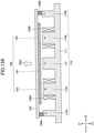
- FIG. 13A is a diagram illustrating a relationship between the directions of the currents and the directions of motions in the first combination.
- the magnetic pole of the first iron core 113A facing the movable yoke 120 becomes an N pole
- the magnetic pole of the second iron core 113B facing the movable yoke 120 also becomes an N pole.
- the poles of the central protruding part 112, the first side protruding part 114A, and the second side protruding part 114B on the surfaces facing the movable yoke 120 become S poles.
- a repulsive force acts between the central protruding part 112 and the first region 161
- a repulsive force acts between the first iron core 113A and the second region 162
- a repulsive force acts between the second iron core 113B and the third region 163. Therefore, a force 190U directed toward the Z1 side acts on the movable yoke 120.
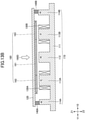
- FIG. 13B is a diagram illustrating a relationship between the directions of the currents and the directions of motions in the second combination.
- the magnetic pole of the first iron core 113A facing the movable yoke 120 becomes an S pole
- the magnetic pole of the second iron core 113B facing the movable yoke 120 also becomes an S pole.
- the poles of the central protruding part 112, the first side protruding part 114A, and the second side protruding part 114B on the surfaces facing the movable yoke 120 become N poles.
- an attractive force acts between the central protruding part 112 and the first region 161; an attractive force acts between the first iron core 113A and the second region 162; and an attractive force acts between the second iron core 113B and the third region 163. Therefore, a force 190D directed toward the Z2 side acts on the movable yoke 120.
- the movable yoke 120 reciprocates in the Z1-Z2 direction.
- the movable yoke 120 vibrates in the Z1-Z2 direction with the neutral position being the position in the initial state.
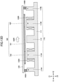
- FIG. 13C is a diagram illustrating a relationship between the directions of the currents and the directions of motions in the third combination.
- the magnetic pole of the first iron core 113A facing the movable yoke 120 becomes an N pole
- the magnetic pole of the second iron core 113B facing the movable yoke 120 becomes an S pole.
- the magnetic pole of the first side protruding part 114A facing the movable yoke 120 becomes an S pole
- the magnetic pole of the second side protruding part 114B facing the movable yoke 120 becomes an N pole.
- FIG. 13D is a diagram illustrating a relationship between the directions of the currents and the directions of motions in the fourth combination.
- the magnetic pole of the first iron core 113A facing the movable yoke 120 becomes an N pole
- the magnetic pole of the second iron core 113B facing the movable yoke 120 becomes an S pole.
- the magnetic pole of the first side protruding part 114A facing the movable yoke 120 becomes an S pole
- the magnetic pole of the second side protruding part 114B facing the movable yoke 120 becomes an N pole.
- the movable yoke 120 reciprocates in the Y1-Y2 direction.
- the movable yoke 120 vibrates in the Y1-Y2 direction with the neutral position being the position in the initial state.
- Such a vibration providing part 2 can be used, for example, by attaching a surface of the movable yoke 120 on the Z1 side to the bottom plate 211 of the housing 260.
- FIG. 14 is a cross-sectional view illustrating a configuration of a vibration generating device according to the second embodiment.
- a vibration generating device 300 includes a housing 310; a diaphragm 312 that is supported by the housing 310 and generates sound by vibrating in the first direction (the Z1-Z2 direction); and a vibration providing part 220 that is attached to the housing 310 to vibrate the housing 310.
- the vibration providing part 220 vibrates the housing 310 in the first direction at a first frequency f1, and vibrates the housing 310 in a second direction orthogonal to the first direction (the X1-X2 direction or the Y1-Y2 direction), at a second frequency f2 that is lower than the first frequency f1.
- the vibration generating device 300 further includes a coupling part 311 that couples the housing 310 with the diaphragm 312.
- the coupling part 311 is thinner than part of the housing 310 connected with the coupling part 311.
- the other elements are substantially the same as those in the first embodiment.
- the housing 310 vibrating in the first direction causes the diaphragm 312 to vibrate in the first direction through the deflection of the coupling part 311, and the diaphragm 312 vibrating the surrounding air generates sound. Also, when vibrating in the second direction, the diaphragm 312 hardly vibrates in the first direction, and hence, the diaphragm 312 does not generate sound.
- vibration at the first frequency f1 in the first direction sound can be presented to a person with virtually no vibration felt by the person, and by vibration at the second frequency f2 in the second direction, vibration can be presented to the person with virtually no sound felt by the person.
- the diaphragm 312 can be integrally formed with the coupling part 311 and the housing 310.
- the housing 310, the coupling part 311, and the diaphragm 312 are made of synthetic resin.
- the diaphragm 312 may be have a thickness equivalent to the thickness of the coupling part 311, or may be thinner or thicker than the coupling part 311.
- the application of the vibration generating device in the present disclosure is not limited in particular, and can be used, for example, for presenting vibration and sound to persons who are riding in an automobile.
- presentation for alerting only the driver to a low-urgency matter can be provided by vibration in the driver's seat
- presentation for alerting all occupants in the automobile to a high-urgency matter can be provided by sound spreading throughout the entire interior of the automobile.
- the location at which the vibration generating device in the present disclosure is installed is not limited in particular, and can be embedded, for example, in the bearing surface or the backrest of the driver's seat.
- vibration and sound may be presented from multiple vibration generating devices to a single user. For example, by using multiple vibration generating devices to present the vibration or sound in multiple directions, lively presentation can be provided.
- sound and vibration can be adequately separated when being presented to the user, in some applications, sound and vibration may be intentionally mixed when being presented to the user.
- a signal at the first frequency f1 (high-frequency signal) and a signal at the second frequency f2 (low-frequency signal) may be input separately, or a signal in which the signal at the first frequency f1 and the signal at the second frequency f2 are superimposed (superimposed signal) may be input.
- FIG. 15A is a diagram illustrating an example of a waveform of a signal at the first frequency f1.
- FIG. 15B is a diagram illustrating an example of a waveform of a signal at the second frequency f2.
- 15C is a diagram illustrating an example of a waveform of a superimposed signal in which the signal of the first frequency f1 and the signal of the second frequency f2 are superimposed.
- the first frequency f1 is set to 20 ⁇ f0 and the second frequency f2 is set to f0.
- the housing can be vibrated in the first direction at the first frequency f1 and in the second direction at the second frequency f2.
Landscapes
- Engineering & Computer Science (AREA)
- Physics & Mathematics (AREA)
- Acoustics & Sound (AREA)
- Signal Processing (AREA)
- Electromagnetism (AREA)
- Mechanical Engineering (AREA)
- Multimedia (AREA)
- Apparatuses For Generation Of Mechanical Vibrations (AREA)
- Details Of Audible-Bandwidth Transducers (AREA)
- Electrostatic, Electromagnetic, Magneto- Strictive, And Variable-Resistance Transducers (AREA)
Abstract
Description
- The present disclosure relates to a vibration generating device.
-
Patent Document 1 discloses a vibration source drive device that has an object to generate sound and vibration exclusively. - Patent Document 1:
Japanese Laid-Open Patent Application No. 2001-121079 - However, even if adopting the vibration source drive device disclosed in
Patent Document 1, it is difficult to generate sound and vibration that are sufficiently separated. - The present disclosure has an object to provide a vibration generating device capable of presenting sound and vibration that are sufficiently separated.
- According to the present disclosure, a vibration generating device is provided that includes a housing; a diaphragm supported by the housing, and configured to generate sound by vibrating in a first direction; and a vibration providing part attached to the housing, and configured to vibrate the housing, wherein the vibration providing part vibrates the housing in the first direction at a first frequency, and vibrates the housing in a second direction at a second frequency lower than the first frequency.
- According to the present disclosure, sound and vibration that are sufficiently separated can be presented.
-
-
FIG. 1A is an exploded perspective view illustrating a configuration of a vibration generating device according to a first embodiment; -
FIG. 1B is a plan view illustrating the configuration of the vibration generating device according to the first embodiment; -
FIG. 1C is a cross-sectional view illustrating the configuration of the vibration generating device according to the first embodiment; -
FIG. 2A is a perspective view illustrating an external appearance of a first example of a vibration providing part; -
FIG. 2B is a perspective view illustrating a state in which the cover is removed from the first example of the vibration providing part; -
FIG. 3 is an exploded perspective view illustrating a configuration of the first example of the vibration providing part; -
FIG. 4 is a perspective view illustrating a configuration of a vibrator in the first example of the vibration providing part; -
FIG. 5A is a perspective view illustrating a configuration of a holder and an elastic supporter in the first example of the vibration providing part; -
FIG. 5B is a front view illustrating the configuration of the holder and the elastic supporter in the first example of the vibration providing part; -
FIG. 6A is a side view illustrating the configuration of the holder and the elastic supporter in the first example of the vibration providing part; -
FIG. 6B is a cross-sectional view illustrating the configuration of the holder and the elastic supporter in the first example of the vibration providing part; -
FIG. 7A is an exploded perspective view illustrating a configuration of a permanent magnet in the first example of the vibration providing part; -
FIG. 7B is a front view illustrating the configuration of the permanent magnet in the first example of the vibration providing part; -
FIG. 8A is a first explanatory diagram illustrating driving directions of a magnetic drive part in the first example of the vibration providing part; -
FIG. 8B is a second explanatory diagram illustrating driving directions of the magnetic drive part in the first example of the vibration providing part; -
FIG. 9A is a first explanatory diagram illustrating driving directions in the first example of the vibration providing part; -
FIG. 9B is a second explanatory diagram illustrating driving directions in the first example of the vibration providing part; -
FIG. 10 is a plan view illustrating a configuration of the second example of the vibration providing part; -
FIG. 11 is a plan view in which a movable yoke and a permanent magnet inFIG. 10 are excluded; -
FIG. 12 is a cross-sectional view illustrating a configuration of the first example of the vibration providing part; -
FIG. 13A is a diagram illustrating a relationship between directions of currents and directions of motions in a first combination; -
FIG. 13B is a diagram illustrating a relationship between directions of currents and directions of motions in a second combination; -
FIG. 13C is a diagram illustrating a relationship between directions of currents and directions of motions in a third combination; -
FIG. 13D is a diagram illustrating a relationship between directions of currents and directions of motions in a 4th combination; -
FIG. 14 is a diagram illustrating a configuration of a vibration generating device according to a second embodiment; -
FIG. 15A is a diagram illustrating an example of a waveform of a signal at a first frequency; -
FIG. 15B is a diagram illustrating an example of a waveform of a signal at a second frequency; and -
FIG. 15C is a diagram illustrating an example of a waveform of a signal in which a first frequency signal is superimposed with a second frequency signal. - In the following, embodiments in the present disclosure will be described with reference to the accompanying drawings. Note that throughout the description and the drawings, for elements having substantially the same functional configurations, duplicate descriptions may be omitted by attaching the same reference codes.
- First, a first embodiment will be described.
FIG. 1A ,1B , and1C are diagram illustrating a configuration of avibration generating device 200 according to a first embodiment.FIG. 1A is an exploded perspective view;FIG. 1B is a plan view; andFIG. 1C is a cross-sectional view along a I-I line inFIG. 1B . Note that the directions in each figure are defined as X1 being left, X2 being right, Y1 being front, Y2 being rear, Z1 being upward, and Z2 being downward. - As illustrated in
FIG. 1A ,1B , and1C , thevibration generating device 200 according to the first embodiment has alower case 210, avibration providing part 220, anupper case 230, and adiaphragm 240. Thelower case 210 and theupper case 230 are included in ahousing 260. Thelower case 210 has a disk-shapedbottom plate 211 and a cylinder-shapedside plate 212 extending upward from an edge of thebottom plate 211. Thevibration providing part 220 is fixed to the top surface of thebottom plate 211 by a double-sided tape 251. Theupper case 230 has a ring-shapedbottom plate 231 having anopening 232 formed at the center, and aguide part 233 provided at an edge of thebottom plate 231 to guide thediaphragm 240. Thediaphragm 240 has a disk shape, and is fixed to the top surface of thebottom plate 231 by a ring-shaped double-sided tape 252 inside theguide part 233, to be held by theupper case 230. For example, theupper case 230 is fixed to thelower case 210 so that thediaphragm 240 is positioned on the upside with respect to theupper case 230. Theupper case 230 may be fixed to thelower case 210 so that thediaphragm 240 is positioned on the lower side with respect to theupper case 230. Theupper case 230 is an example of a holder. - The
diaphragm 240 is supported by thehousing 260, and generates sound by vibrating in a first direction (the Z1-Z2 direction). Thevibration providing part 220 is attached to thehousing 260, to vibrate thehousing 260. Thevibration providing part 220 vibrates thehousing 260 in the first direction at the first frequency f1, and vibrates thehousing 260 in a second direction at a second frequency f2 that is lower than the first frequency f1. For example, the second direction is a direction different from the first direction, and favorably is a direction (the X1-X2 direction or the Y1-Y2 direction) orthogonal to the first direction (the Z1-Z2 direction). - For example, the
diaphragm 240 can be integrally formed with thehousing 260. For example, thediaphragm 240 can be integrally formed with theupper case 230. Also, for example, thehousing 260 and thediaphragm 240 are made of synthetic resin or made of metal. - In the
vibration generating device 200, thehousing 260 vibrating in the first direction causes thediaphragm 240 to vibrate in the first direction, and thediaphragm 240 vibrating the surrounding air generates sound. The first frequency f1 is not limited in particular, and may be set to be, for example, greater than or equal to 200 Hz and less than or equal to 6 kHz; in particular, it is favorable that the range is set to be, for example, greater than or equal to 1 kHz and less than or equal to 4 kHz that can be easily detected by the auditory perception of a person. Even if thehousing 260 vibrates at a frequency in a range that can be easily detected by the auditory perception of a person, the vibration is hardly detected by the person through the tactile perception. Therefore, vibration at the first frequency f1 in the first direction can present sound to a person without causing the person to feel the vibration substantially. - Also, the second frequency f2 is not limited in particular, and may be set to be, for example, less than or equal to 600 Hz; in particular, it is favorable that the range is set to be, for example, greater than or equal to 100 Hz and less than or equal to 500 Hz that can be easily detected by the tactile perception of a person. Even in the case where the first frequency f1 is greater than or equal to 200 Hz and less than or equal to 600 Hz, the second frequency f2 simply needs to be lower than the first frequency f1. In some cases, the auditory perception of a person can detect frequencies of sound that are easily detected by the tactile perception; however, when vibrating in the second direction, the
diaphragm 240 hardly vibrates in the first direction, and thereby, thediaphragm 240 does not generate sound. Therefore, vibration at the second frequency f2 in the second direction can present vibration to a person without causing the person to feel sound substantially. - Here, the
vibration providing part 1 according to the first example of thevibration providing part 220 will be described.FIGs. 2A and 2B are first explanatory diagrams illustrating a configuration of thevibration providing part 1.FIG. 2A is a perspective view illustrating an external appearance of thevibration providing part 1; andFIG. 2B is a perspective view illustrating thevibration providing part 1 in a state of acover 12 being removed.FIG. 3 is a second explanatory diagram illustrating the configuration of thevibration providing part 1, and is an exploded perspective view of thevibration providing part 1.FIG. 4 is an explanatory diagram illustrating a configuration of thevibrator 20 in thevibration providing part 1, and is a perspective view of thevibrator 20. -
FIGs. 5A and 5B are first explanatory diagrams illustrating a configuration of theholder 30 and theelastic supporter 40 in thevibration providing part 1.FIG. 5A is a perspective view of theholder 30 and theelastic supporter 40; andFIG. 5B is a front view of theholder 30 and theelastic supporter 40 in thevibration providing part 1.FIGs. 6A and 6B are second explanatory diagrams illustrating a configuration of theholder 30 and theelastic supporter 40 in thevibration providing part 1.FIG. 6A is a side view in the case of viewing theholder 30 and theelastic supporter 40 from the right; andFIG. 6B is a cross-sectional view corresponding to a cross section ofFIG. 5B along a cross section A1-A1.FIGs. 7A and 7B are explanatory diagrams illustrating a configuration of the permanent magnet in thevibration providing part 1.FIG. 7A is an exploded perspective view of thepermanent magnet 70 on the rear side;FIG. 7B is a front view of thepermanent magnet 70 on the rear side. -
FIGs. 8A and 8B are explanatory diagrams illustrating driving directions of themagnetic drive part 50 in thevibration providing part 1, in which themagnetic core 61 is viewed from the front.FIG. 8A illustrates a direction of a magnetic force exerted by thepermanent magnet 70 on thefront edge 61F of the core 61 when thefront edge 61F of thecore 61 is magnetized to be an N pole; andFIG. 8B illustrates a direction of a magnetic force exerted by thepermanent magnet 70 on thefront edge 61F of the core 61 when thefront edge 61F of thecore 61 is magnetized to be an S pole. InFIGs. 8A and 8B , a solid-line arrow indicates a direction of a magnetic force acting on themagnetic core 61. -
FIGs. 9A and 9B are explanatory diagram illustrating vibration directions of thevibrator 20 in thevibration providing part 1, in which thevibrator 20, theholder 30, and theelastic supporter 40 are viewed from the front.FIG. 9A illustrates a vibration direction of thevibrator 20 when theelectromagnet 60 generates an alternating magnetic field at the same frequency as the first natural frequency; andFIG. 9B illustrates a vibration direction of thevibrator 20 when theelectromagnet 60 generates an alternating magnetic field at the same frequency as the second natural frequency. InFIGs. 9A and 9B , a solid-line arrow indicates a direction in which it is easier for thevibrator 20 to generate vibration, namely, the vibration direction of thevibrator 20, and a dashed-line arrow indicates a direction in which it is difficult for thevibrator 20 to generate vibration. - In the
vibration providing part 1 according to the first example, the Z1-Z2 direction is an example of a first direction; the X1-X2 direction is an example of a second direction; and the Y1-Y2 direction is an example of a third direction. - First, a configuration of the
vibration providing part 1 will be described by usingFIGs. 2A, 2B ,3 ,4 ,5A, 5B ,6A, 6B ,7A, and 7B . As illustrated inFIG. 2A, 2B , and3 , thevibration providing part 1 includes ahousing 10, thevibrator 20, theholder 30, the twoelastic supporters 40, and themagnetic drive part 50. - As illustrated in
FIG. 2A, 2B , and3 , thehousing 10 is constituted by combining a main body 11 and thecover 12. The main body 11 is a box-like member having generally a rectangular shape formed by processing a metal plate, and has acontainer 11a as a recessed part that is generally a rectangular parallelepiped, and recessed downward from anupper end 11b of the main body 11. Thecover 12 is a plate-like member having generally rectangular shape formed by processing a metal plate, and is attached to theupper end 11b of the main body 11 to cover thecontainer 11a from the top. Thehousing 10 is an example of an inside housing. - As illustrated in
FIG. 2B ,3 , and4 , thevibrator 20 is a member having generally a rectangular shape contained in thecontainer 11a of thehousing 10. In thevibrator 20, theelectromagnet 60 as part of themagnetic drive part 50 is arranged. - The
holder 30 and theelastic supporter 40 are integrally formed by processing a metal plate having a spring property, to have a predetermined shape. As illustrated inFIG. 5A, 5B ,6A, and 6B , theholder 30 is a box-like part being generally a rectangular parallelepiped. As illustrated inFIG. 2B and3 , in theholder 30, the lower part of thevibrator 20 is contained to be held. - As illustrated in
FIG. 5A, 5B ,6A, and 6B , theelastic supporter 40 is a plate spring formed by folding a metal plate extending in the left-right direction multiple times so as to have the folds extend along the front-back direction. Among the twoelastic supporters 40, one extends from theleft end 30L of theholder 30 to the left side, and the other extends from theright end 30R of theholder 30 to the right side. In the following, theelastic supporter 40 extending from theleft end 30L of theholder 30 to the left side will be referred to as theelastic supporter 40 on the left side; and theelastic supporter 40 extending from theright end 30R of theholder 30 to the right side will be referred to as theelastic supporter 40 on the right side. - Also, as illustrated in
FIG. 5A, 5B ,6A, and 6B , theelastic supporter 40 has three foldedparts 41, twoflat parts 42, and anattachment 43. The foldedpart 41 is a part at which the metal plate is folded along a folds. Theflat part 42 is a part having generally a rectangular shape extending from one of the three foldedparts 41 to another, and has sides along the direction of the folds and sides along the extending direction. Further, theelastic supporter 40 is formed so as to make a dimension along the direction of the folds of the flat part 42 (referred to as the width dimension of theflat part 42, hereafter) greater than a dimension along the extending direction of the flat part 42 (referred to as the length dimension of theflat part 42, hereafter). Also, anopening 42a having generally a rectangular shape is formed at a position away from the outer periphery of theflat part 42. - Note that a plate spring having such a folded structure as in the
elastic supporter 40, has a feature in that elastic deformation occurs more easily in directions orthogonal to the folds (the left-right direction and the up-down direction). In other words, such a plate spring can be elastically deformed along the left-right direction due to expansion and contraction, and elastically deformed along the up-down direction by deflection. On the other hand, such a plate spring also has a feature in that deformation hardly occurs in the direction along the folds (in the front-back direction), and hence, is suitable as a member for suppressing movement along the front-back direction. - Also, in a plate spring having such a folded structure, elastic deformation along the left-right direction due to expansion and contraction is normally more likely to occur, compared to elastic deformation along the up-down direction due to deflection. Therefore, defining the modulus of elasticity of the
elastic supporter 40 in the left-right direction as the first modulus of elasticity, and defining the modulus of elasticity of theelastic supporter 40 in the up-down direction as the second modulus of elasticity, then, the first modulus of elasticity and the second modulus of elasticity take values different from each other. - The
attachment 43 is formed at the tip of theelastic supporter 40. An engagingclaw part 43a is formed at a predetermined position of theattachment 43. Further, by having of the engagingclaw part 43a engaged with the main body 11 of thehousing 10, theelastic supporter 40 is attached to thehousing 10. Further, by elastic deformation along the left-right direction and along the up-down direction, theelastic supporter 40 supports thevibrator 20 to be capable of vibrating along the left-right direction and along the up-down direction. - Note that being supported by the
elastic supporter 40, thevibrator 20 vibrates along the left-right direction at the first natural frequency that is determined according to the first modulus of elasticity and the mass of thevibrator 20, and vibrates along the up-down direction at the second natural frequency that is determined according to the second modulus of elasticity and the mass of thevibrator 20. Further, as the first modulus of elasticity and the second modulus of elasticity take different values from each other, the first natural frequency and the second natural frequency take different values from each other. - As illustrated in
FIG. 3 , themagnetic drive part 50 is configured to include theelectromagnet 60 arranged facing the vibrator 20 (a first magnetic field generating part), and the twopermanent magnets 70 arranged facing the housing 10 (a second magnetic field generating part). As illustrated inFIG. 4 , theelectromagnet 60 has amagnetic core 61, abobbin 62, acoil 63, and a terminal 64. Themagnetic core 61 is a member having a prismatic shape made of a ferromagnetic material, and extends along the front-back direction. Thebobbin 62 is a member having a cylindrical shape made of an insulator, and covers the outer periphery of thecore 61. Thecoil 63 is formed by winding a wire around the outer periphery of thebobbin 62. The terminal 64 connects both ends of thecoil 63 to an external circuit (not illustrated) via a member for wiring (not illustrated). - The
electromagnet 60 generates a magnetic field along the front-back direction by causing an alternating current to flow through thecoil 63, to magnetize thefront edge 61F and therear edge 61R of the core 61 to have different poles. Further, by adopting an alternating current as the current flowing through thecoil 63, the magnetic field generated by theelectromagnet 60 is an alternating magnetic field in which the direction of the magnetic field changes in response to change in the direction of the current. Further, when thefront edge 61F of thecore 61 is serving as an S pole, therear edge 61R is serving as an N pole, and when thefront edge 61F of thecore 61 is serving as an N pole, therear edge 61R is serving as an S pole. The timing and the frequency of the alternating magnetic field generated by theelectromagnet 60 are controlled by the external circuit described above. - As illustrated in
FIG. 3 ,7A, and 7B , thepermanent magnet 70 is a plate-like magnet being generally a rectangular parallelepiped. The twopermanent magnets 70 are arranged on the front edge side and on the rear edge side of thehousing 10, respectively, so as to be positioned on an extended line in the front-back direction of themagnetic core 61 included in theelectromagnet 60 of the vibrator 20 (refer to as the extended line in the front-back direction of thevibrator 20, hereafter). Also, as illustrated inFIG. 7A and 7B , thepermanent magnet 70 has a magnetizedface 71 that is formed to have generally a rectangular shape, and edges along the left-right direction and along the up-down direction. Further, themagnetized face 71 of thepermanent magnet 70 is opposite to themagnetic core 61 of theelectromagnet 60 in in the frond-back direction. - Also, the
permanent magnet 70 has aslit 72 that is formed to extend diagonally from the upper left to the lower right of themagnetized face 71. Further, themagnetized face 71 is partitioned into twomagnetized regions 73 by theslit 72, and the twomagnetized regions 73 are magnetized to be magnetic poles different from each other. In this way, thepermanent magnet 70 is magnetized to have different magnetic poles aligned along the left-right direction and along the up-down direction, respectively. - In the following, the
permanent magnet 70 arranged on the front edge side of thehousing 10 will be referred to as thepermanent magnet 70 on the front side; and thepermanent magnet 70 arranged on the rear edge side of thehousing 10 will be referred to as thepermanent magnet 70 on the rear side. Also, among the twomagnetized regions 73, a region on the lower left side will be referred to as the firstmagnetized region 73a; and a region on the upper right side will be referred to as the secondmagnetized region 73b. Further, it is assumed in the following description that in thepermanent magnet 70 on the front side, the firstmagnetized region 73a becomes an S pole and the secondmagnetized region 73b becomes an N pole; and in thepermanent magnet 70 on the rear side, the firstmagnetized region 73a becomes an N pole and the secondmagnetized region 73b becomes an S pole. - Also, a
yoke 74 as a member made of a ferromagnetic material is attached to thepermanent magnet 70, for directing the magnetic field generated by thepermanent magnet 70 toward theelectromagnet 60. Thevibration providing part 1 has a configuration like this. - Next, operations of the
vibration providing part 1 will be described by usingFIGs. 8A, 8B ,9A, and 9B . As described earlier, themagnetic drive part 50 includes theelectromagnet 60 arranged facing thevibrator 20, and the twopermanent magnets 70 arranged facing thehousing 10. Further, theelectromagnet 60 generates an alternating magnetic field by causing an alternating current to flow through thecoil 63, to magnetize thefront edge 61F and therear edge 61R of thecore 61. Also, thepermanent magnet 70 is arranged on thehousing 10 side so to be opposite theelectromagnet 60 in front and in the rear. Further, on themagnetized surface 71 of thepermanent magnet 70, the firstmagnetized region 73a and the secondmagnetized region 73b that are magnetized to be different magnetic poles. - Further, as illustrated in
FIG. 8A , when thefront edge 61F of thecore 61 is magnetized to be an N pole, thefront edge 61F of thecore 61 attracts the firstmagnetized region 73a of thepermanent magnet 70 on the front side to each other, and repels the secondmagnetized region 73b from each other. Although not illustrated, when thefront edge 61F of thecore 61 is magnetized to be an N pole, therear edge 61R of thecore 61 is magnetized to be an S pole; and therear edge 61R of thecore 61 attracts the firstmagnetized region 73a of thepermanent magnet 70 on the rear side to each other, and repels the secondmagnetized region 73b from each other. As a result, the magnetic forces act on thevibrator 20 in the left direction and in the downward direction. - Also, as illustrated in
FIG. 8B , when thefront edge 61F of thecore 61 is magnetized to be an S pole, thefront edge 61F of thecore 61 repels the firstmagnetized region 73a of thepermanent magnet 70 on the front side from each other, and attracts the secondmagnetized region 73b to each other. Although not illustrated, when thefront edge 61F of thecore 61 is magnetized to be an S pole, therear edge 61R of thecore 61 is magnetized to be an N pole; and therear edge 61R of themagnetic core 61 repels the firstmagnetized region 73a of thepermanent magnet 70 on the rear side from each other, and attracts the secondmagnetized region 73b to each other. As a result, the magnetic forces act on thevibrator 20 in the right direction and in the UP direction. - In this way, in the
magnetic drive part 50, every time the direction of the magnetic field generated by theelectromagnet 60 is inverted, thefront edge 61F and therear edge 61R of themagnetic core 61 of theelectromagnet 60 attract or repel the firstmagnetized region 73a of thepermanent magnet 70 to or from each other, and repel or attract the secondmagnetized region 73b from or to each other. Further, themagnetic drive part 50 uses the magnetic forces between theelectromagnet 60 and thepermanent magnet 70, to drive thevibrator 20 in the left-right direction and in the up-down direction. - On the other hand, as described earlier, the
vibrator 20 is supported by theelastic supporter 40, to be capable of vibrating along the left-right direction and along the up-down direction. Further, thevibrator 20 vibrates along the left-right direction at the first natural frequency that is determined according to the first modulus of elasticity and the mass of thevibrator 20, and vibrates along the up-down direction at the second natural frequency that is determined according to the second modulus of elasticity and the mass of thevibrator 20. - Therefore, as illustrated in
FIG. 9A , when theelectromagnet 60 generates an alternating magnetic field at the same frequency as the first natural frequency, for thevibrator 20, it becomes easier to vibrate in the left-right direction, and harder to vibrate in the up-down direction. As a result, thevibrator 20 starts vibrating along the left-right direction. Also, as illustrated inFIG. 9B , when theelectromagnet 60 generates an alternating magnetic field at the same frequency as the second natural frequency, for thevibrator 20, it becomes easier to vibrate in the up-down direction, and harder to vibrate in the left-right direction. As a result, thevibrator 20 starts vibrating along the up-down direction. - By using such a relationship between the frequency of the alternating magnetic field and the easiness of vibration of the
vibrator 20, themagnetic drive part 50 vibrates thevibrator 20 along the left-right direction by the alternating magnetic field at the same frequency as the first natural frequency, and vibrates thevibrator 20 along the up-down direction by the alternating magnetic field at the same frequency as the second natural frequency. In the following, vibrating thevibrator 20 along the left-right direction by the alternating magnetic field at the same frequency as the first natural frequency, will be referred as to driving thevibrator 20 in the left-right direction at the first natural frequency; and vibrating thevibrator 20 along the up-down direction by the alternating magnetic field at the same frequency as the second natural frequency, will be referred as to driving thevibrator 20 in the up-down direction at the second natural frequency. - Next, a method of stabilizing vibrating operations of the
vibrator 20 will be described. As described earlier, a plate spring having such a folded structure like theelastic supporter 40, has a feature in that elastic deformation occurs easier in a direction orthogonal to the folds, whereas deformation hardly occurs in the direction along the folds. Therefore, in thevibration providing part 1, by using the feature of the plate spring, deformation of theelastic supporter 40 along the front-back direction is suppressed; and thereby, movement of thevibrator 20 along the front-back direction is suppressed, and vibrating operations of thevibrator 20 along the left-right direction and along the up-down direction are stabilized. - Moreover, in the plate spring having such a folded structure, a width dimension of the
flat part 42 greater than the length dimension of theflat part 42 makes deformation along the folds more difficult. In thevibration providing part 1, by using the feature of the plate spring having such a folded structure, theelastic supporter 40 is formed so as to have the width dimension of theflat part 42 greater than the length dimension of theflat part 42, and thereby, deformation of theelastic supporter 40 along the front-back direction can be suppressed more easily. - Also, in the plate spring having such a folded structure, although the outer periphery of the
flat part 42 greatly influences the difficulty of deformation of theelastic supporter 40 along the folds, the influence of part of theflat part 42 away from the outer periphery (part closer to the center) is smaller than the influence of the outer periphery of theflat part 42. On the other hand, by forming theopening 42a at a part away from the outer periphery of theflat part 42, the mechanical strength in directions orthogonal to the folds of the flat part 42 (in the left-right direction and in the up-down direction) can be reduced, and thereby, theelastic supporter 40 can be made elastically deformable more easily in the directions orthogonal to the folds. - By using the feature of the plate spring having such a folded structure, the
vibration providing part 1 according to the first example is configured to have theopening 42a formed at a position away from the outer periphery of theflat part 42, so as to have elastic deformation occur easier along the left-right direction and along the up-down direction, while the deformability of theelastic supporter 40 along the front-back direction is suppressed. Further, by adjusting the dimensions of theopening 42a, the elastic deformability of theelastic supporter 40 along the left-right direction and along the up-down direction can be adjusted. - Next, effects of the
vibration providing part 1 will be described. In thevibration providing part 1, theelastic supporter 40 is a plate spring formed to have the multiple foldedparts 41 in which the folds are folded along the front-back direction (third direction) orthogonal to the left-right direction (first direction) and to the up-down direction (second direction), and the twoflat parts 42 that have generally a rectangular shape and extend from one of the multiple foldedparts 41 to another. A plate spring having such a folded structure, has a feature in that elastic deformation occurs easier in a direction orthogonal to the folds, whereas deformation hardly occurs in the direction along the folds. Therefore, elastic deformation of theelastic supporter 40 along the left-right direction and along the up-down direction can occur easily, and deformability of theelastic supporter 40 along the front-back direction can be suppressed. As a result, even when a force along the front-back direction acts on thevibrator 20 by a magnetic force between the electromagnet 60 (the first magnetic field generating part) and the permanent magnet 70 (the second magnetic field generating part), movement of thevibrator 20 along the front-back direction can be suppressed, and vibrating operations along the left-right direction and along the up-down direction of thevibrator 20 can be stabilized. - Also, in the
vibration providing part 1, by forming theopening 42a at a position away from the outer periphery of theflat part 42, while suppressing the deformability of theelastic supporter 40 along the front-back direction, elastic deformation can occur easier along the left-right direction and along the up-down direction. Further, by adjusting the dimensions of theopening 42a, the elastic deformability of theelastic supporter 40 along the left-right direction and along the up-down direction can be adjusted. As a result, while stabilizing the vibrating operations of thevibrator 20, thevibrator 20 can be easily vibrated along the left-right direction and along the up-down direction, and the easiness of vibration of thevibrator 20 can be adjusted. - Also, in the
vibration providing part 1, by forming theelastic supporter 40 so as to have the width dimension of the flat part 42 (the dimension in the direction along the folds)greater than the length dimension of the flat part 42 (the dimension along the extending direction), the deformation of theelastic supporter 40 along the front-back direction can be further suppressed, and the vibrating operations of thevibrator 20 can be further stabilized. - Also, in the
vibration providing part 1, themagnetic drive part 50 driving thevibrator 20 at the first natural frequency corresponding to the first modulus of elasticity and the mass of thevibrator 20, makes thevibrator 20 easily vibrated along the left-right direction, and hardly vibrated along the up-down direction. Also, themagnetic drive part 50 driving thevibrator 20 at the second natural frequency corresponding to the second modulus of elasticity and the mass of thevibrator 20, makes thevibrator 20 easily vibrated along the up-down direction, and hardly vibrated along the left-right direction. As a result, while stabilizing the vibrating operations of thevibrator 20, desired vibrating operations of thevibrator 20 along the left-right direction and along the up-down direction can be implemented. - Also, in the
vibration providing part 1, by the alternating magnetic field generated by theelectromagnet 60, themagnetic core 61 on theelectromagnet 60 side can be attracted to or repelled from the firstmagnetized region 73a as one of the magnetic poles on thepermanent magnet 70 side, and the core 61 can be repelled from or attracted to the secondmagnetized region 73b as the other pole on thepermanent magnet 70 side. Further, by using the magnetic forces between theelectromagnet 60 and thepermanent magnets 70, thevibrator 20 can be easily vibrated along the left-right direction and along the up-down direction. Moreover, even when the magnetic forces act between thepermanent magnets 70 and theelectromagnet 60, deformation of theelastic supporter 40 along the front-back direction is suppressed; therefore, the vibrating operations of thevibrator 20 can be stabilized. Therefore, such avibration providing part 1 is suitable in the case of driving thevibrator 20 by using the magnetic forces between theelectromagnet 60 and thepermanent magnets 70. - Such a
vibration providing part 1 can be used, for example, by attaching the lower end of the main body 11 or thecover 12 to thebottom plate 211 of thehousing 260. - As long as the predetermined functions can be implemented, the configuration of the
vibration providing part 1 may be changed appropriately. For example, twoelastic supporters 40 may be attached directly to thevibrator 20. In this case, theholder 30 becomes unnecessary. Also, thevibration providing part 1 may further include members other than those described above. - Also, as long as the predetermined functions can be implemented, the materials and/or the shapes of the
housing 10, theholder 30, and theelastic supporter 40 may be changed appropriately. For example, the number of folds of the plate spring as theelastic supporter 40 may be a number other than that described above. Also, the shape of theflat part 42 and/or the shape of theopening 42a may be shapes other than those described above. Also, theelastic supporter 40 may be formed using a separate member from theholder 30, and then, combined with theholder 30. - Also, as long as the predetermined functions can be implemented, the configuration of the
magnetic drive part 50 may be changed appropriately. For example, thepermanent magnet 70 may be arranged on either one of the front edge side or the rear edge side of thehousing 10. Also, as long as different magnetic poles are arranged along the left-right direction and along the up-down direction, respectively, the shape of theslit 72 may be other than that described above. Also, multiple permanent magnets magnetized to be different magnetic poles along the left-right direction and along the up-down direction may be arranged in thehousing 10. - Also, as long as the predetermined functions can be implemented, the
magnetic drive part 50 may drive thevibrator 20 at a vibration frequency other than the first natural frequency and the second natural frequency. For example, themagnetic drive part 50 not only drives thevibrator 20 along the left-right direction at the first natural frequency and drives thevibrator 20 along the up-down direction at the second natural frequency, but also may drive thevibrator 20 in an oblique direction at an intermediate vibration frequency between the first natural frequency and the second natural frequency. - Next, a
vibration providing part 2 according to a second example of thevibration providing part 220 will be described.FIG. 10 is a plan view illustrating a configuration of thevibration providing part 2;FIG. 11 is a plan view in which the movable yoke and the permanent magnet are removed fromFIG. 10 ; andFIG. 12 is a cross-sectional view illustrating the configuration of thevibration providing part 2.FIG. 6 corresponds to a cross sectional view along a line I-I inFIGs. 4 and5 . - In the
vibration providing part 2 according to the second example, the Z1-Z2 direction is an example of a first direction; and the Y1-Y2 direction is an example of a second direction. - As illustrated in
FIGs. 10 to 12 , thevibration providing part 2 includes a fixedyoke 110, amovable yoke 120, afirst excitation coil 130A, asecond excitation coil 130B, afirst rubber 140A, asecond rubber 140B, and apermanent magnet 160. The fixedyoke 110 has a plate-shapedbase 111 having a generally rectangular planar shape. The axial core direction of thefirst excitation coil 130A and thesecond excitation coil 130B is parallel to the Z1-Z2 direction. Themovable yoke 120 is an example of a first yoke, the fixedyoke 110 is an example of a second yoke, and thefirst rubber 140A and thesecond rubber 140B are examples of elastic support members. - The fixed
yoke 110 further includes a centralprotruding part 112 protruding upward (on the Z1 side) from the center of thebase 111; a firstside protruding part 114A protruding upward from an edge (front edge) of the base 111 on the Y1 side in the longitudinal direction; and a secondside protruding part 114B protruding upward from an edge (rear edge) of the base 111 on the Y2 side in the longitudinal direction. The firstside protruding part 114A and the secondside protruding part 114B are arranged at positions between which the central protrudingparts 112 is interposed in the X1-X2 direction. The fixedyoke 110 further includes afirst iron core 113A protruding upward from thebase 111, between the central protrudingpart 112 and the firstside protruding part 114A; and asecond iron core 113B protruding upward from thebase 111, between the central protrudingpart 112 and the secondside protruding part 114B. Thefirst excitation coil 130A is wound around thefirst iron core 113A, and thesecond excitation coil 130B is wound around thesecond iron core 113B. Thefirst rubber 140A is arranged on the firstside protruding part 114A, and thesecond rubber 140B is arranged on the secondside protruding part 114B. The centralprotruding part 112 is an example of a first protruding part, and the firstside protruding part 114A and the secondside protruding part 114B are examples of second protruding parts. - The
movable yoke 120 is plate-shaped, and has a generally rectangular planar shape. Themovable yoke 120 contacts thefirst rubber 140A and thesecond rubber 140B at its edges in the longitudinal direction. Thepermanent magnet 160 is attached to a surface of themovable yoke 120 on the fixedyoke 110 side. Thepermanent magnet 160 includes afirst region 161, asecond region 162 positioned on the Y1 side of thefirst region 161, and athird region 163 positioned on the Y2 side of thefirst region 161. For example, thefirst region 161 is magnetized to be an S pole, and the second andthird regions permanent magnet 160 is attached to themovable yoke 120 at substantially the center in plan view, so that thefirst region 161 is opposite to the central protrudingpart 112; aboundary 612 between thefirst region 161 and thesecond region 162 is opposite to thefirst excitation coil 130A; and aboundary 613 between thefirst region 161 and thethird region 163 is opposite to thesecond excitation coil 130B. Also, theboundary 612 is positioned on the Y2 side relative to the axial core of thefirst excitation coil 130A, and theboundary 613 is positioned on the Y1 side relative to the axial core of thesecond excitation coil 130B. In other words, theboundary 612 is positioned on the Y2 side relative to the center offirst iron core 113A, and theboundary 613 is positioned on the Y1 side relative to the center ofsecond iron core 113B. Thepermanent magnet 160 magnetizes the fixedyoke 110 and themovable yoke 120, and the magnetic attractive force biases themovable yoke 120 in the Z1-Z2 direction toward the fixedyoke 110. Also, the magnetic attractive force biases both ends of themovable yoke 120 in the Y1-Y2 direction to approach the firstside protruding part 114A and the secondside protruding part 114B, respectively. - When vibration is generated in the
housing 260, thevibration providing part 2 is driven so that the directions of respective currents flowing in thefirst excitation coil 130A and thesecond excitation coil 130B are inverted alternately. In other words, by alternately inverting the direction of the current flowing in each of thefirst excitation coil 130A and thesecond excitation coil 130B, the pole on a surface of thefirst iron core 113A facing themovable yoke 120 and the pole on a surface of thesecond iron core 113B facing themovable yoke 120 are to alternately inverted independently from each other. As a result, according to the direction of a current flowing through thefirst excitation coil 130A, and the direction of a current flowing through thesecond excitation coil 130B, thepermanent magnet 160 and themovable yoke 120 reciprocate in the Y1-Y2 direction or the Z1-Z2 direction. A relationship between directions of currents and directions of motions will be described later. - For example, the
first rubber 140A and thesecond rubber 140B have a rectangular planar shape whose longitudinal direction corresponds to the X1-X2 direction. Thefirst rubber 140A is interposed between the firstside protruding part 114A and themovable yoke 120, and thesecond rubber 140B is interposed between the secondside protruding part 114B and themovable yoke 120. In other words, thefirst rubber 140A and thesecond rubber 140B are interposed between thefixed yoke 110 and themovable yoke 120. Therefore, unless intentionally disassembled, thefirst rubber 140A and thesecond rubber 140B are held between thefixed yoke 110 and themovable yoke 120. Note that thefirst rubber 140A may be fixed to the top surface of the firstside protruding part 114A, fixed to the bottom surface of themovable yoke 120, or fixed to the both; and thesecond rubber 140B may be fixed to the upper surface of the secondside protruding part 114B, fixed to the bottom surface of themovable yoke 120, or fixed to the both. - Here, a relationship between directions of currents and directions of motions will be described. In total, there are four types of combinations in terms of the direction of a current flowing through the
first excitation coil 130A, and the direction of a current flowing through thesecond excitation coil 130B. - In the first combination, when viewed from the Z1 side, currents flow through the
first excitation coil 130A and thesecond excitation coil 130B counter-clockwise.FIG. 13A is a diagram illustrating a relationship between the directions of the currents and the directions of motions in the first combination. In the first combination, as illustrated inFIG. 13A , the magnetic pole of thefirst iron core 113A facing themovable yoke 120 becomes an N pole, the magnetic pole of thesecond iron core 113B facing themovable yoke 120 also becomes an N pole. On the other hand, the poles of the central protrudingpart 112, the firstside protruding part 114A, and the secondside protruding part 114B on the surfaces facing themovable yoke 120 become S poles. As a result, a repulsive force acts between the central protrudingpart 112 and thefirst region 161, a repulsive force acts between thefirst iron core 113A and thesecond region 162, and a repulsive force acts between thesecond iron core 113B and thethird region 163. Therefore, aforce 190U directed toward the Z1 side acts on themovable yoke 120. - In the second combination, when viewed from the Z1 side, currents flow through the
first excitation coil 130A and thesecond excitation coil 130B clockwise.FIG. 13B is a diagram illustrating a relationship between the directions of the currents and the directions of motions in the second combination. In the second combination, as illustrated inFIG. 13B , the magnetic pole of thefirst iron core 113A facing themovable yoke 120 becomes an S pole, the magnetic pole of thesecond iron core 113B facing themovable yoke 120 also becomes an S pole. On the other hand, the poles of the central protrudingpart 112, the firstside protruding part 114A, and the secondside protruding part 114B on the surfaces facing themovable yoke 120 become N poles. As a result, an attractive force acts between the central protrudingpart 112 and thefirst region 161; an attractive force acts between thefirst iron core 113A and thesecond region 162; and an attractive force acts between thesecond iron core 113B and thethird region 163. Therefore, aforce 190D directed toward the Z2 side acts on themovable yoke 120. - Therefore, by repeating the first combination and the second combination so that currents flows through the
first excitation coil 130A and thesecond excitation coil 130B in the same direction, themovable yoke 120 reciprocates in the Z1-Z2 direction. In other words, by energizing thefirst excitation coil 130A and thesecond excitation coil 130B, themovable yoke 120 vibrates in the Z1-Z2 direction with the neutral position being the position in the initial state. - In the third combination, when viewed from the Z1 side, a current flows through the
first excitation coil 130A counter-clockwise, and a current flows through thesecond excitation coil 130B clockwise.FIG. 13C is a diagram illustrating a relationship between the directions of the currents and the directions of motions in the third combination. In the third combination, as illustrated inFIG. 13C , the magnetic pole of thefirst iron core 113A facing themovable yoke 120 becomes an N pole, and the magnetic pole of thesecond iron core 113B facing themovable yoke 120 becomes an S pole. Also, the magnetic pole of the firstside protruding part 114A facing themovable yoke 120 becomes an S pole, and the magnetic pole of the secondside protruding part 114B facing themovable yoke 120 becomes an N pole. As a result, an attractive force acts between the firstside protruding part 114A and thesecond region 162; an attractive force acts between thefirst iron core 113A and thefirst region 161; a repulsive force acts between thesecond iron core 113B and thefirst region 161; and a repulsive force acts between the secondside protruding part 114B and thethird region 163. Therefore, aforce 190L directed toward the Y1 side acts on themovable yoke 120. - In the fourth combination, when viewed from the Z1 side, a current flows through the
first excitation coil 130A clockwise, and a current flows through thesecond excitation coil 130B counter-clockwise.FIG. 13D is a diagram illustrating a relationship between the directions of the currents and the directions of motions in the fourth combination. In the fourth combination, as illustrated inFIG. 13D , the magnetic pole of thefirst iron core 113A facing themovable yoke 120 becomes an N pole, and the magnetic pole of thesecond iron core 113B facing themovable yoke 120 becomes an S pole. Also, the magnetic pole of the firstside protruding part 114A facing themovable yoke 120 becomes an S pole, and the magnetic pole of the secondside protruding part 114B facing themovable yoke 120 becomes an N pole. As a result, a repulsive force acts between the firstside protruding part 114A and thesecond region 162; a repulsive force acts between thefirst iron core 113A and thefirst region 161; an attractive force acts between thesecond iron core 113B and thefirst region 161; and an attractive force acts between the secondside protruding part 114B and thethird region 163. Therefore, aforce 190R directed toward the Y2 side acts on themovable yoke 120. - Therefore, by repeating the third combination and the fourth combination so that currents flows through the
first excitation coil 130A and thesecond excitation coil 130B in the opposite directions, themovable yoke 120 reciprocates in the Y1-Y2 direction. In other words, by energizing thefirst excitation coil 130A and thesecond excitation coil 130B, themovable yoke 120 vibrates in the Y1-Y2 direction with the neutral position being the position in the initial state. - Such a
vibration providing part 2 can be used, for example, by attaching a surface of themovable yoke 120 on the Z1 side to thebottom plate 211 of thehousing 260. - Next, a second embodiment will be described. The second embodiment differs from the first embodiment in terms of the relationship between the housing and the diaphragm.
FIG. 14 is a cross-sectional view illustrating a configuration of a vibration generating device according to the second embodiment. - As illustrated in
FIG. 14 , avibration generating device 300 according to the second embodiment includes ahousing 310; adiaphragm 312 that is supported by thehousing 310 and generates sound by vibrating in the first direction (the Z1-Z2 direction); and avibration providing part 220 that is attached to thehousing 310 to vibrate thehousing 310. Thevibration providing part 220 vibrates thehousing 310 in the first direction at a first frequency f1, and vibrates thehousing 310 in a second direction orthogonal to the first direction (the X1-X2 direction or the Y1-Y2 direction), at a second frequency f2 that is lower than the first frequency f1.Thevibration generating device 300 further includes acoupling part 311 that couples thehousing 310 with thediaphragm 312. Thecoupling part 311 is thinner than part of thehousing 310 connected with thecoupling part 311. The other elements are substantially the same as those in the first embodiment. - In the
vibration generating device 300, thehousing 310 vibrating in the first direction causes thediaphragm 312 to vibrate in the first direction through the deflection of thecoupling part 311, and thediaphragm 312 vibrating the surrounding air generates sound. Also, when vibrating in the second direction, thediaphragm 312 hardly vibrates in the first direction, and hence, thediaphragm 312 does not generate sound. - Therefore, as in the first embodiment, by vibration at the first frequency f1 in the first direction, sound can be presented to a person with virtually no vibration felt by the person, and by vibration at the second frequency f2 in the second direction, vibration can be presented to the person with virtually no sound felt by the person.
- For example, the
diaphragm 312 can be integrally formed with thecoupling part 311 and thehousing 310. Also, for example, thehousing 310, thecoupling part 311, and thediaphragm 312 are made of synthetic resin. Thediaphragm 312 may be have a thickness equivalent to the thickness of thecoupling part 311, or may be thinner or thicker than thecoupling part 311. - The application of the vibration generating device in the present disclosure is not limited in particular, and can be used, for example, for presenting vibration and sound to persons who are riding in an automobile. For example, presentation for alerting only the driver to a low-urgency matter can be provided by vibration in the driver's seat, whereas presentation for alerting all occupants in the automobile to a high-urgency matter can be provided by sound spreading throughout the entire interior of the automobile. The location at which the vibration generating device in the present disclosure is installed is not limited in particular, and can be embedded, for example, in the bearing surface or the backrest of the driver's seat.
- Also, vibration and sound may be presented from multiple vibration generating devices to a single user. For example, by using multiple vibration generating devices to present the vibration or sound in multiple directions, lively presentation can be provided.
- Also, according to the first and second embodiments, although sound and vibration can be adequately separated when being presented to the user, in some applications, sound and vibration may be intentionally mixed when being presented to the user.
- Also, as signals input into the vibration generating device in the present disclosure, a signal at the first frequency f1 (high-frequency signal) and a signal at the second frequency f2 (low-frequency signal) may be input separately, or a signal in which the signal at the first frequency f1 and the signal at the second frequency f2 are superimposed (superimposed signal) may be input.
FIG. 15A is a diagram illustrating an example of a waveform of a signal at the first frequency f1.FIG. 15B is a diagram illustrating an example of a waveform of a signal at the second frequency f2.FIG. 15C is a diagram illustrating an example of a waveform of a superimposed signal in which the signal of the first frequency f1 and the signal of the second frequency f2 are superimposed. Here, the first frequency f1 is set to 20×f0 and the second frequency f2 is set to f0. For example, by providing a signal processor in the vibration providing part to separate the superimposed signal illustrated inFIG. 15C into the high-frequency signal illustrated inFIG. 15A and the low-frequency signal illustrated inFIG. 15B , the housing can be vibrated in the first direction at the first frequency f1 and in the second direction at the second frequency f2. - As described above, the favorable embodiments and the like have been described in detail; note that the embodiments and the like can be changed and replaced in various ways without deviating from the scope described in the claims.
- The present international application claims priority based on
Japanese Patent Application No. 2019-047616, filed on March 14, 2019 -
- 1, 2, 220
- vibration providing part
- 10
- housing (inside housing)
- 11
- main body
- 11a
- container
- 12
- cover
- 20
- vibrator
- 30
- holder
- 40
- elastic supporter
- 41
- fold
- 42
- flat part
- 42a
- opening
- 43
- attachment
- 43a
- engaging claw part
- 50
- magnetic drive part
- 60
- electromagnet (first magnetic field generating part)
- 61
- magnetic core
- 62
- bobbin
- 63
- coil
- 64
- terminal
- 70
- permanent magnet (second magnetic field generating part)
- 71
- magnetized surface
- 72
- slit
- 73
- magnetized region
- 73a
- first magnetized region
- 73b
- second magnetized region
- 74
- yoke
- 110
- fixed yoke (second yoke)
- 111
- base
- 112
- central protruding part (first protruding part)
- 113A
- first iron core
- 113B
- second iron core
- 114A
- first side protruding part (second protruding part)
- 114B
- second side protruding part (second protruding part)
- 120
- movable yoke (first yoke)
- 130A
- first excitation coil
- 130B
- second excitation coil
- 140A
- first rubber
- 140B
- second rubber
- 160
- permanent magnet
- 161
- first region
- 162
- second region
- 163
- third region
- 210
- lower case
- 230
- upper case (holder)
- 240, 312
- diaphragm
- 260, 310
- housing
- 311
- coupling part
Claims (8)
- A vibration generating device comprising:a housing;a diaphragm supported by the housing, and configured to generate sound by vibrating in a first direction; anda vibration providing part attached to the housing, and configured to vibrate the housing,wherein the vibration providing part vibrates the housing in the first direction at a first frequency, and vibrates the housing in a second direction at a second frequency lower than the first frequency.
- The vibration generating device as claimed in claim 1, wherein a superimposed signal in which a signal at the first frequency and a signal at the second frequency are superimposed, is input, and
wherein the vibration providing part separates the superimposed signal into the signal at the first frequency and the signal at the second frequency, to vibrate the housing in the first direction at the first frequency, and vibrate the housing in a second direction at the second frequency. - The vibration generating device as claimed in claim 1 or 2, wherein the vibration providing part includesan inside housing,a vibrator contained in the inside housing,an elastic supporter configured to support the vibrator to be capable of vibrating along the first direction and along the second direction, anda magnetic drive part configured to drive the vibrator along the first direction and along the second direction by using magnetic forces,wherein the magnetic drive part includesa first magnetic field generating part arranged on a vibrator side, anda second magnetic field generating part arranged on an inside housing side, as to be positioned on an extended line of the vibrator in a third direction orthogonal to the first direction and to the second direction,wherein the elastic supporter is formed with a plate spring that includesa plurality of folded parts each having a fold folded along the third direction, anda flat part extending from one of the folded parts to another of the folded parts.
- The vibration generating device as claimed in claim 1 or 2, wherein the vibration providing part includesa first yoke,a second yoke arranged to be opposite to the first yoke in the first direction,a permanent magnet attached to a surface of the first yoke facing a second yoke, anda first excitation coil and a second excitation coil attached to the second yoke to generate magnetic flux when being energized,wherein the second yoke includesa base, anda first protruding part protruding from the base toward the first yoke, between the first excitation coil and the second excitation coil,wherein the first excitation coil and the second excitation coil are arranged to have the first protruding part interposed in-between in the second direction,wherein an axial core direction of the first excitation coil and the second excitation coil is parallel to the first direction,wherein the permanent magnet includesa first region,a second region positioned on one side of the first region in the second direction, anda third region positioned on another side of the first region in the second direction,wherein the first region is magnetized to be a first magnetic pole,wherein the second region and the third region are magnetized to be second magnetic poles,wherein the first region is opposite to the first protruding part,wherein a boundary between the first region and the second region is opposite to the first excitation coil, andwherein a boundary between the first region and the third region is opposite to the second excitation coil.
- The vibration generating device as claimed in any one of claims 1 to 4, wherein the first frequency is greater than or equal to 200 Hz and less than or equal to 6 kHz, and
wherein the second frequency is less than or equal to 600 Hz. - The vibration generating device as claimed in any one of claims 1 to 5, wherein the housing includes a holder configured to hold the diaphragm, and
wherein as viewed in the first direction, part of the diaphragm overlapping the holder is fixed to the holder. - The vibration generating device as claimed in any one of claims 1 to 5, wherein the diaphragm is integrally formed with the housing.
- The vibration generating device as claimed in any one of claims 1 to 7, wherein the housing and the diaphragm are made of synthetic resin or made of metal.
Applications Claiming Priority (2)
| Application Number | Priority Date | Filing Date | Title |
|---|---|---|---|
| JP2019047616 | 2019-03-14 | ||
| PCT/JP2020/007014 WO2020184147A1 (en) | 2019-03-14 | 2020-02-21 | Vibration generation device |
Publications (3)
| Publication Number | Publication Date |
|---|---|
| EP3939709A1 true EP3939709A1 (en) | 2022-01-19 |
| EP3939709A4 EP3939709A4 (en) | 2022-11-23 |
| EP3939709B1 EP3939709B1 (en) | 2024-10-23 |
Family
ID=72427982
Family Applications (1)
| Application Number | Title | Priority Date | Filing Date |
|---|---|---|---|
| EP20770919.7A Active EP3939709B1 (en) | 2019-03-14 | 2020-02-21 | Vibration generation device |
Country Status (5)
| Country | Link |
|---|---|
| US (1) | US12103040B2 (en) |
| EP (1) | EP3939709B1 (en) |
| JP (1) | JP7253613B2 (en) |
| CN (1) | CN113382808B (en) |
| WO (1) | WO2020184147A1 (en) |
Families Citing this family (1)
| Publication number | Priority date | Publication date | Assignee | Title |
|---|---|---|---|---|
| JP7407290B2 (en) * | 2020-07-14 | 2023-12-28 | アルプスアルパイン株式会社 | Vehicle systems and vibration generators |
Family Cites Families (12)
| Publication number | Priority date | Publication date | Assignee | Title |
|---|---|---|---|---|
| CA2258762C (en) * | 1996-06-21 | 2002-12-31 | Sanyo Electric Co., Ltd. | Notifying vibration generator and portable communications device wherein the generator is used |
| JP3344385B2 (en) | 1999-10-22 | 2002-11-11 | ヤマハ株式会社 | Vibration source drive |
| JP2002159916A (en) * | 2000-11-24 | 2002-06-04 | Citizen Electronics Co Ltd | Multifunction type acoustic device |
| DE10238325A1 (en) * | 2002-08-16 | 2004-03-11 | Fraunhofer-Gesellschaft zur Förderung der angewandten Forschung e.V. | speaker |
| JP3974068B2 (en) * | 2003-03-27 | 2007-09-12 | 日本信号株式会社 | Planar type electromagnetic actuator |
| JP5840427B2 (en) * | 2011-09-09 | 2016-01-06 | アルプス電気株式会社 | Vibration generator |
| JP6151235B2 (en) * | 2014-10-22 | 2017-06-21 | 日本電信電話株式会社 | Acceleration generator and information presentation method |
| JP6253157B2 (en) * | 2014-11-14 | 2017-12-27 | アルプス電気株式会社 | Vibration generator |
| KR101648955B1 (en) * | 2015-03-24 | 2016-08-19 | 주식회사 예일전자 | Sensory signal output apparatus and vibration related with the spring |
| US10623840B2 (en) * | 2017-03-24 | 2020-04-14 | Harman International Industries, Incorporated | Loudspeaker acoustic diversity aperture frame |
| JP2019025390A (en) * | 2017-07-26 | 2019-02-21 | アルプス電気株式会社 | Vibration generation device |
| JP2019047616A (en) | 2017-09-01 | 2019-03-22 | 小堀 しづ | How is the universe now made? |
-
2020
- 2020-02-21 EP EP20770919.7A patent/EP3939709B1/en active Active
- 2020-02-21 CN CN202080012365.XA patent/CN113382808B/en active Active
- 2020-02-21 JP JP2021504889A patent/JP7253613B2/en active Active
- 2020-02-21 WO PCT/JP2020/007014 patent/WO2020184147A1/en not_active Ceased
-
2021
- 2021-08-30 US US17/446,351 patent/US12103040B2/en active Active
Also Published As
| Publication number | Publication date |
|---|---|
| JPWO2020184147A1 (en) | 2020-09-17 |
| US20210387231A1 (en) | 2021-12-16 |
| EP3939709B1 (en) | 2024-10-23 |
| EP3939709A4 (en) | 2022-11-23 |
| US12103040B2 (en) | 2024-10-01 |
| CN113382808B (en) | 2022-08-16 |
| WO2020184147A1 (en) | 2020-09-17 |
| JP7253613B2 (en) | 2023-04-06 |
| CN113382808A (en) | 2021-09-10 |
Similar Documents
| Publication | Publication Date | Title |
|---|---|---|
| JP7677704B2 (en) | Vibration actuator and vibration presentation device | |
| CN108855846B (en) | Vibration generating device | |
| US20200274432A1 (en) | Vibration generating device | |
| US20190304650A1 (en) | Vibration actuator and vibration providing apparatus | |
| JP7407290B2 (en) | Vehicle systems and vibration generators | |
| KR20210047576A (en) | Radial magnet actuator | |
| US12293654B2 (en) | Bodily vibration generation device and bodily vibration presentation apparatus | |
| JP7300524B2 (en) | Tactile presentation device | |
| EP3939709B1 (en) | Vibration generation device | |
| WO2019021969A1 (en) | Vibration generating device | |
| JP2019025390A (en) | Vibration generation device | |
| JP7404515B2 (en) | Vibration generator | |
| JP6526162B2 (en) | Vibration generator | |
| JP6539714B2 (en) | Vibration generator | |
| JP6499261B2 (en) | Vibration generator | |
| JP2010098461A (en) | Flat speaker | |
| US20200028426A1 (en) | Electronic device | |
| JP2019211982A (en) | Electronic apparatus | |
| WO2019013083A1 (en) | Vibration generating device | |
| JP2018029483A (en) | Vibration generator | |
| JP6539715B2 (en) | Vibration generator | |
| JP6416364B2 (en) | Vibration generator | |
| JP2018170844A (en) | Power generation device and input apparatus provided with the same | |
| WO2018012085A1 (en) | Power generation device |
Legal Events
| Date | Code | Title | Description |
|---|---|---|---|
| STAA | Information on the status of an ep patent application or granted ep patent |
Free format text: STATUS: THE INTERNATIONAL PUBLICATION HAS BEEN MADE |
|
| PUAI | Public reference made under article 153(3) epc to a published international application that has entered the european phase |
Free format text: ORIGINAL CODE: 0009012 |
|
| STAA | Information on the status of an ep patent application or granted ep patent |
Free format text: STATUS: REQUEST FOR EXAMINATION WAS MADE |
|
| 17P | Request for examination filed |
Effective date: 20210831 |
|
| AK | Designated contracting states |
Kind code of ref document: A1 Designated state(s): AL AT BE BG CH CY CZ DE DK EE ES FI FR GB GR HR HU IE IS IT LI LT LU LV MC MK MT NL NO PL PT RO RS SE SI SK SM TR |
|
| DAV | Request for validation of the european patent (deleted) | ||
| DAX | Request for extension of the european patent (deleted) | ||
| A4 | Supplementary search report drawn up and despatched |
Effective date: 20221020 |
|
| RIC1 | Information provided on ipc code assigned before grant |
Ipc: H04R 7/16 20060101ALI20221014BHEP Ipc: H04R 9/02 20060101ALI20221014BHEP Ipc: H04R 13/00 20060101ALI20221014BHEP Ipc: H04R 1/00 20060101ALI20221014BHEP Ipc: B06B 1/04 20060101AFI20221014BHEP |
|
| STAA | Information on the status of an ep patent application or granted ep patent |
Free format text: STATUS: EXAMINATION IS IN PROGRESS |
|
| 17Q | First examination report despatched |
Effective date: 20230602 |
|
| GRAP | Despatch of communication of intention to grant a patent |
Free format text: ORIGINAL CODE: EPIDOSNIGR1 |
|
| STAA | Information on the status of an ep patent application or granted ep patent |
Free format text: STATUS: GRANT OF PATENT IS INTENDED |
|
| INTG | Intention to grant announced |
Effective date: 20240618 |
|
| GRAS | Grant fee paid |
Free format text: ORIGINAL CODE: EPIDOSNIGR3 |
|
| GRAA | (expected) grant |
Free format text: ORIGINAL CODE: 0009210 |
|
| STAA | Information on the status of an ep patent application or granted ep patent |
Free format text: STATUS: THE PATENT HAS BEEN GRANTED |
|
| AK | Designated contracting states |
Kind code of ref document: B1 Designated state(s): AL AT BE BG CH CY CZ DE DK EE ES FI FR GB GR HR HU IE IS IT LI LT LU LV MC MK MT NL NO PL PT RO RS SE SI SK SM TR |
|
| REG | Reference to a national code |
Ref country code: GB Ref legal event code: FG4D |
|
| REG | Reference to a national code |
Ref country code: CH Ref legal event code: EP |
|
| REG | Reference to a national code |
Ref country code: DE Ref legal event code: R096 Ref document number: 602020039953 Country of ref document: DE |
|
| REG | Reference to a national code |
Ref country code: IE Ref legal event code: FG4D |
|
| REG | Reference to a national code |
Ref country code: LT Ref legal event code: MG9D |
|
| REG | Reference to a national code |
Ref country code: NL Ref legal event code: MP Effective date: 20241023 |
|
| REG | Reference to a national code |
Ref country code: AT Ref legal event code: MK05 Ref document number: 1734421 Country of ref document: AT Kind code of ref document: T Effective date: 20241023 |
|
| PG25 | Lapsed in a contracting state [announced via postgrant information from national office to epo] |
Ref country code: NL Free format text: LAPSE BECAUSE OF FAILURE TO SUBMIT A TRANSLATION OF THE DESCRIPTION OR TO PAY THE FEE WITHIN THE PRESCRIBED TIME-LIMIT Effective date: 20241023 |
|
| PG25 | Lapsed in a contracting state [announced via postgrant information from national office to epo] |
Ref country code: NL Free format text: LAPSE BECAUSE OF FAILURE TO SUBMIT A TRANSLATION OF THE DESCRIPTION OR TO PAY THE FEE WITHIN THE PRESCRIBED TIME-LIMIT Effective date: 20241023 |
|
| PG25 | Lapsed in a contracting state [announced via postgrant information from national office to epo] |
Ref country code: HR Free format text: LAPSE BECAUSE OF FAILURE TO SUBMIT A TRANSLATION OF THE DESCRIPTION OR TO PAY THE FEE WITHIN THE PRESCRIBED TIME-LIMIT Effective date: 20241023 Ref country code: PT Free format text: LAPSE BECAUSE OF FAILURE TO SUBMIT A TRANSLATION OF THE DESCRIPTION OR TO PAY THE FEE WITHIN THE PRESCRIBED TIME-LIMIT Effective date: 20250224 Ref country code: IS Free format text: LAPSE BECAUSE OF FAILURE TO SUBMIT A TRANSLATION OF THE DESCRIPTION OR TO PAY THE FEE WITHIN THE PRESCRIBED TIME-LIMIT Effective date: 20250223 |
|
| PG25 | Lapsed in a contracting state [announced via postgrant information from national office to epo] |
Ref country code: FI Free format text: LAPSE BECAUSE OF FAILURE TO SUBMIT A TRANSLATION OF THE DESCRIPTION OR TO PAY THE FEE WITHIN THE PRESCRIBED TIME-LIMIT Effective date: 20241023 |
|
| PG25 | Lapsed in a contracting state [announced via postgrant information from national office to epo] |
Ref country code: BG Free format text: LAPSE BECAUSE OF FAILURE TO SUBMIT A TRANSLATION OF THE DESCRIPTION OR TO PAY THE FEE WITHIN THE PRESCRIBED TIME-LIMIT Effective date: 20241023 |
|
| PG25 | Lapsed in a contracting state [announced via postgrant information from national office to epo] |
Ref country code: ES Free format text: LAPSE BECAUSE OF FAILURE TO SUBMIT A TRANSLATION OF THE DESCRIPTION OR TO PAY THE FEE WITHIN THE PRESCRIBED TIME-LIMIT Effective date: 20241023 |
|
| PG25 | Lapsed in a contracting state [announced via postgrant information from national office to epo] |
Ref country code: NO Free format text: LAPSE BECAUSE OF FAILURE TO SUBMIT A TRANSLATION OF THE DESCRIPTION OR TO PAY THE FEE WITHIN THE PRESCRIBED TIME-LIMIT Effective date: 20250123 |
|
| PG25 | Lapsed in a contracting state [announced via postgrant information from national office to epo] |
Ref country code: LV Free format text: LAPSE BECAUSE OF FAILURE TO SUBMIT A TRANSLATION OF THE DESCRIPTION OR TO PAY THE FEE WITHIN THE PRESCRIBED TIME-LIMIT Effective date: 20241023 Ref country code: GR Free format text: LAPSE BECAUSE OF FAILURE TO SUBMIT A TRANSLATION OF THE DESCRIPTION OR TO PAY THE FEE WITHIN THE PRESCRIBED TIME-LIMIT Effective date: 20250124 Ref country code: AT Free format text: LAPSE BECAUSE OF FAILURE TO SUBMIT A TRANSLATION OF THE DESCRIPTION OR TO PAY THE FEE WITHIN THE PRESCRIBED TIME-LIMIT Effective date: 20241023 |
|
| PG25 | Lapsed in a contracting state [announced via postgrant information from national office to epo] |
Ref country code: PL Free format text: LAPSE BECAUSE OF FAILURE TO SUBMIT A TRANSLATION OF THE DESCRIPTION OR TO PAY THE FEE WITHIN THE PRESCRIBED TIME-LIMIT Effective date: 20241023 |
|
| PG25 | Lapsed in a contracting state [announced via postgrant information from national office to epo] |
Ref country code: RS Free format text: LAPSE BECAUSE OF FAILURE TO SUBMIT A TRANSLATION OF THE DESCRIPTION OR TO PAY THE FEE WITHIN THE PRESCRIBED TIME-LIMIT Effective date: 20250123 |
|
| PG25 | Lapsed in a contracting state [announced via postgrant information from national office to epo] |
Ref country code: SM Free format text: LAPSE BECAUSE OF FAILURE TO SUBMIT A TRANSLATION OF THE DESCRIPTION OR TO PAY THE FEE WITHIN THE PRESCRIBED TIME-LIMIT Effective date: 20241023 |
|
| PG25 | Lapsed in a contracting state [announced via postgrant information from national office to epo] |
Ref country code: DK Free format text: LAPSE BECAUSE OF FAILURE TO SUBMIT A TRANSLATION OF THE DESCRIPTION OR TO PAY THE FEE WITHIN THE PRESCRIBED TIME-LIMIT Effective date: 20241023 |
|
| PG25 | Lapsed in a contracting state [announced via postgrant information from national office to epo] |
Ref country code: EE Free format text: LAPSE BECAUSE OF FAILURE TO SUBMIT A TRANSLATION OF THE DESCRIPTION OR TO PAY THE FEE WITHIN THE PRESCRIBED TIME-LIMIT Effective date: 20241023 |
|
| PG25 | Lapsed in a contracting state [announced via postgrant information from national office to epo] |
Ref country code: RO Free format text: LAPSE BECAUSE OF FAILURE TO SUBMIT A TRANSLATION OF THE DESCRIPTION OR TO PAY THE FEE WITHIN THE PRESCRIBED TIME-LIMIT Effective date: 20241023 |
|
| REG | Reference to a national code |
Ref country code: DE Ref legal event code: R097 Ref document number: 602020039953 Country of ref document: DE |
|
| PG25 | Lapsed in a contracting state [announced via postgrant information from national office to epo] |
Ref country code: SK Free format text: LAPSE BECAUSE OF FAILURE TO SUBMIT A TRANSLATION OF THE DESCRIPTION OR TO PAY THE FEE WITHIN THE PRESCRIBED TIME-LIMIT Effective date: 20241023 |
|
| PG25 | Lapsed in a contracting state [announced via postgrant information from national office to epo] |
Ref country code: CZ Free format text: LAPSE BECAUSE OF FAILURE TO SUBMIT A TRANSLATION OF THE DESCRIPTION OR TO PAY THE FEE WITHIN THE PRESCRIBED TIME-LIMIT Effective date: 20241023 |
|
| PG25 | Lapsed in a contracting state [announced via postgrant information from national office to epo] |
Ref country code: IT Free format text: LAPSE BECAUSE OF FAILURE TO SUBMIT A TRANSLATION OF THE DESCRIPTION OR TO PAY THE FEE WITHIN THE PRESCRIBED TIME-LIMIT Effective date: 20241023 |
|
| PLBE | No opposition filed within time limit |
Free format text: ORIGINAL CODE: 0009261 |
|
| STAA | Information on the status of an ep patent application or granted ep patent |
Free format text: STATUS: NO OPPOSITION FILED WITHIN TIME LIMIT |
|
| PG25 | Lapsed in a contracting state [announced via postgrant information from national office to epo] |
Ref country code: SE Free format text: LAPSE BECAUSE OF FAILURE TO SUBMIT A TRANSLATION OF THE DESCRIPTION OR TO PAY THE FEE WITHIN THE PRESCRIBED TIME-LIMIT Effective date: 20241023 |
|
| PG25 | Lapsed in a contracting state [announced via postgrant information from national office to epo] |
Ref country code: MC Free format text: LAPSE BECAUSE OF FAILURE TO SUBMIT A TRANSLATION OF THE DESCRIPTION OR TO PAY THE FEE WITHIN THE PRESCRIBED TIME-LIMIT Effective date: 20241023 |
|
| REG | Reference to a national code |
Ref country code: CH Ref legal event code: PL |
|
| 26N | No opposition filed |
Effective date: 20250724 |
|
| PG25 | Lapsed in a contracting state [announced via postgrant information from national office to epo] |
Ref country code: LU Free format text: LAPSE BECAUSE OF NON-PAYMENT OF DUE FEES Effective date: 20250221 |
|
| PG25 | Lapsed in a contracting state [announced via postgrant information from national office to epo] |
Ref country code: CH Free format text: LAPSE BECAUSE OF NON-PAYMENT OF DUE FEES Effective date: 20250228 |
|
| GBPC | Gb: european patent ceased through non-payment of renewal fee |
Effective date: 20250221 |
|
| REG | Reference to a national code |
Ref country code: BE Ref legal event code: MM Effective date: 20250228 |
|
| PG25 | Lapsed in a contracting state [announced via postgrant information from national office to epo] |
Ref country code: GB Free format text: LAPSE BECAUSE OF NON-PAYMENT OF DUE FEES Effective date: 20250221 |
|
| PG25 | Lapsed in a contracting state [announced via postgrant information from national office to epo] |
Ref country code: FR Free format text: LAPSE BECAUSE OF NON-PAYMENT OF DUE FEES Effective date: 20250228 |
|
| PG25 | Lapsed in a contracting state [announced via postgrant information from national office to epo] |
Ref country code: BE Free format text: LAPSE BECAUSE OF NON-PAYMENT OF DUE FEES Effective date: 20250228 |
|
| PG25 | Lapsed in a contracting state [announced via postgrant information from national office to epo] |
Ref country code: IE Free format text: LAPSE BECAUSE OF NON-PAYMENT OF DUE FEES Effective date: 20250221 |
|
| PGFP | Annual fee paid to national office [announced via postgrant information from national office to epo] |
Ref country code: DE Payment date: 20260218 Year of fee payment: 7 |