EP3939250B1 - Battery triggering for activation of an optical data interconnect system - Google Patents
Battery triggering for activation of an optical data interconnect system Download PDFInfo
- Publication number
- EP3939250B1 EP3939250B1 EP20770551.8A EP20770551A EP3939250B1 EP 3939250 B1 EP3939250 B1 EP 3939250B1 EP 20770551 A EP20770551 A EP 20770551A EP 3939250 B1 EP3939250 B1 EP 3939250B1
- Authority
- EP
- European Patent Office
- Prior art keywords
- hdmi
- optical
- signals
- electrical
- power
- Prior art date
- Legal status (The legal status is an assumption and is not a legal conclusion. Google has not performed a legal analysis and makes no representation as to the accuracy of the status listed.)
- Active
Links
Images


Classifications
-
- H—ELECTRICITY
- H04—ELECTRIC COMMUNICATION TECHNIQUE
- H04N—PICTORIAL COMMUNICATION, e.g. TELEVISION
- H04N21/00—Selective content distribution, e.g. interactive television or video on demand [VOD]
- H04N21/40—Client devices specifically adapted for the reception of or interaction with content, e.g. set-top-box [STB]; Operations thereof
- H04N21/43—Processing of content or additional data, e.g. demultiplexing additional data from a digital video stream; Elementary client operations, e.g. monitoring of home network or synchronising decoder's clock; Client middleware
- H04N21/436—Interfacing a local distribution network, e.g. communicating with another STB or one or more peripheral devices inside the home
- H04N21/4363—Adapting the video stream to a specific local network, e.g. a Bluetooth® network
- H04N21/43632—Adapting the video stream to a specific local network, e.g. a Bluetooth® network involving a wired protocol, e.g. IEEE 1394
- H04N21/43635—HDMI
-
- H—ELECTRICITY
- H02—GENERATION; CONVERSION OR DISTRIBUTION OF ELECTRIC POWER
- H02J—ELECTRIC POWER NETWORKS; CIRCUIT ARRANGEMENTS OR SYSTEMS FOR SUPPLYING OR DISTRIBUTING ELECTRIC POWER; SYSTEMS FOR STORING ELECTRIC ENERGY
- H02J7/00—Circuit arrangements for charging or discharging batteries or for supplying loads from batteries
- H02J7/865—Battery or charger load switching, e.g. concurrent charging and load supply
-
- G—PHYSICS
- G02—OPTICS
- G02B—OPTICAL ELEMENTS, SYSTEMS OR APPARATUS
- G02B6/00—Light guides; Structural details of arrangements comprising light guides and other optical elements, e.g. couplings
- G02B6/24—Coupling light guides
- G02B6/42—Coupling light guides with opto-electronic elements
- G02B6/4201—Packages, e.g. shape, construction, internal or external details
- G02B6/4274—Electrical aspects
- G02B6/4284—Electrical aspects of optical modules with disconnectable electrical connectors
-
- H—ELECTRICITY
- H01—ELECTRIC ELEMENTS
- H01S—DEVICES USING THE PROCESS OF LIGHT AMPLIFICATION BY STIMULATED EMISSION OF RADIATION [LASER] TO AMPLIFY OR GENERATE LIGHT; DEVICES USING STIMULATED EMISSION OF ELECTROMAGNETIC RADIATION IN WAVE RANGES OTHER THAN OPTICAL
- H01S5/00—Semiconductor lasers
- H01S5/02—Structural details or components not essential to laser action
- H01S5/026—Monolithically integrated components, e.g. waveguides, monitoring photo-detectors, drivers
-
- H—ELECTRICITY
- H01—ELECTRIC ELEMENTS
- H01S—DEVICES USING THE PROCESS OF LIGHT AMPLIFICATION BY STIMULATED EMISSION OF RADIATION [LASER] TO AMPLIFY OR GENERATE LIGHT; DEVICES USING STIMULATED EMISSION OF ELECTROMAGNETIC RADIATION IN WAVE RANGES OTHER THAN OPTICAL
- H01S5/00—Semiconductor lasers
- H01S5/10—Construction or shape of the optical resonator, e.g. extended or external cavity, coupled cavities, bent-guide, varying width, thickness or composition of the active region
- H01S5/18—Surface-emitting [SE] lasers, e.g. having both horizontal and vertical cavities
- H01S5/183—Surface-emitting [SE] lasers, e.g. having both horizontal and vertical cavities having only vertical cavities, e.g. vertical cavity surface-emitting lasers [VCSEL]
- H01S5/18302—Surface-emitting [SE] lasers, e.g. having both horizontal and vertical cavities having only vertical cavities, e.g. vertical cavity surface-emitting lasers [VCSEL] comprising an integrated optical modulator
-
- H—ELECTRICITY
- H02—GENERATION; CONVERSION OR DISTRIBUTION OF ELECTRIC POWER
- H02J—ELECTRIC POWER NETWORKS; CIRCUIT ARRANGEMENTS OR SYSTEMS FOR SUPPLYING OR DISTRIBUTING ELECTRIC POWER; SYSTEMS FOR STORING ELECTRIC ENERGY
- H02J7/00—Circuit arrangements for charging or discharging batteries or for supplying loads from batteries
- H02J7/90—Regulation of charging or discharging current or voltage
-
- H—ELECTRICITY
- H03—ELECTRONIC CIRCUITRY
- H03F—AMPLIFIERS
- H03F3/00—Amplifiers with only discharge tubes or only semiconductor devices as amplifying elements
- H03F3/04—Amplifiers with only discharge tubes or only semiconductor devices as amplifying elements with semiconductor devices only
- H03F3/08—Amplifiers with only discharge tubes or only semiconductor devices as amplifying elements with semiconductor devices only controlled by light
- H03F3/085—Amplifiers with only discharge tubes or only semiconductor devices as amplifying elements with semiconductor devices only controlled by light using opto-couplers between stages
-
- H—ELECTRICITY
- H03—ELECTRONIC CIRCUITRY
- H03F—AMPLIFIERS
- H03F3/00—Amplifiers with only discharge tubes or only semiconductor devices as amplifying elements
- H03F3/45—Differential amplifiers
- H03F3/45071—Differential amplifiers with semiconductor devices only
- H03F3/45076—Differential amplifiers with semiconductor devices only characterised by the way of implementation of the active amplifying circuit in the differential amplifier
- H03F3/45475—Differential amplifiers with semiconductor devices only characterised by the way of implementation of the active amplifying circuit in the differential amplifier using IC blocks as the active amplifying circuit
-
- H—ELECTRICITY
- H03—ELECTRONIC CIRCUITRY
- H03F—AMPLIFIERS
- H03F3/00—Amplifiers with only discharge tubes or only semiconductor devices as amplifying elements
- H03F3/50—Amplifiers in which input is applied to, or output is derived from, an impedance common to input and output circuits of the amplifying element, e.g. cathode follower
-
- H—ELECTRICITY
- H04—ELECTRIC COMMUNICATION TECHNIQUE
- H04B—TRANSMISSION
- H04B10/00—Transmission systems employing electromagnetic waves other than radio-waves, e.g. infrared, visible or ultraviolet light, or employing corpuscular radiation, e.g. quantum communication
- H04B10/25—Arrangements specific to fibre transmission
-
- H—ELECTRICITY
- H04—ELECTRIC COMMUNICATION TECHNIQUE
- H04B—TRANSMISSION
- H04B10/00—Transmission systems employing electromagnetic waves other than radio-waves, e.g. infrared, visible or ultraviolet light, or employing corpuscular radiation, e.g. quantum communication
- H04B10/80—Optical aspects relating to the use of optical transmission for specific applications, not provided for in groups H04B10/03 - H04B10/70, e.g. optical power feeding or optical transmission through water
- H04B10/801—Optical aspects relating to the use of optical transmission for specific applications, not provided for in groups H04B10/03 - H04B10/70, e.g. optical power feeding or optical transmission through water using optical interconnects, e.g. light coupled isolators, circuit board interconnections
- H04B10/803—Free space interconnects, e.g. between circuit boards or chips
-
- H—ELECTRICITY
- H04—ELECTRIC COMMUNICATION TECHNIQUE
- H04B—TRANSMISSION
- H04B10/00—Transmission systems employing electromagnetic waves other than radio-waves, e.g. infrared, visible or ultraviolet light, or employing corpuscular radiation, e.g. quantum communication
- H04B10/80—Optical aspects relating to the use of optical transmission for specific applications, not provided for in groups H04B10/03 - H04B10/70, e.g. optical power feeding or optical transmission through water
- H04B10/806—Arrangements for feeding power
- H04B10/808—Electrical power feeding of an optical transmission system
-
- H—ELECTRICITY
- H04—ELECTRIC COMMUNICATION TECHNIQUE
- H04N—PICTORIAL COMMUNICATION, e.g. TELEVISION
- H04N5/00—Details of television systems
- H04N5/76—Television signal recording
- H04N5/765—Interface circuits between an apparatus for recording and another apparatus
-
- H—ELECTRICITY
- H04—ELECTRIC COMMUNICATION TECHNIQUE
- H04N—PICTORIAL COMMUNICATION, e.g. TELEVISION
- H04N7/00—Television systems
- H04N7/22—Adaptations for optical transmission
-
- H—ELECTRICITY
- H03—ELECTRONIC CIRCUITRY
- H03F—AMPLIFIERS
- H03F2203/00—Indexing scheme relating to amplifiers with only discharge tubes or only semiconductor devices as amplifying elements covered by H03F3/00
- H03F2203/45—Indexing scheme relating to differential amplifiers
- H03F2203/45528—Indexing scheme relating to differential amplifiers the FBC comprising one or more passive resistors and being coupled between the LC and the IC
Definitions
- D1 discloses a communication network that includes an optical receiver. This optical receiver can be selectively powered up or powered down depending on detected network activity. D1 also discloses a single power supply that supplies power to the transmitter and the receiver, while also providing power for each multimedia device in the associated network, and for the network interface itself. A battery circuit is provided to provide power to the receiver circuit. However, D1 does not disclose any differential circuitry for conversion of optical signals to differential electrical signals. Also, D1 does not disclose a power tap, or any HDMI electro-optical connectivity.
- D2 discloses a cable for automatically maintaining a connection between a digital audio/video source and a digital audio/video sink.
- the cable is disclosed to be an optical cable that is capable of switching between a first communication method (e.g., clock stretching) and a second communication method (e.g., data mirroring) without intervention by a user.
- Signals supported by the cable include HDMI cables, with one end of the cable being connected to an HDMI signal source, and the other end being connected to an HDMI signal sink.
- Reference D2 is related to HDMI data communication via an optical communication channel; however, this reference does not disclose aspects related to a power tap or a voltage regulator. Power to the connector (cable) is provided by a 5V signal in D2; however, this power signal is not used to trigger HDMI power activation of HDMI differential electrical data ports at the HDMI sink.
- the present disclosure relates to system for optical interconnect.
- a system and method for emulating electrical HDMI interconnects with an optical system is described.
- High Definition (HD) signals are typically transmitted from one system to another using cables carrying DVI (Digital Video Interface) or HDMI (High Definition Multimedia Interface) signals.
- DVI/HDMI signals are conveyed over copper cables using a form of differential signaling called Transition Minimized Differential Signaling (TMDS).
- TMDS Transition Minimized Differential Signaling
- video, audio, and control data can be carried on three TMDS data channels with a separate TMDS channel for clock information.
- HDMI 2.1 introduced another differential signaling form called Fixed Rate Link (FRL) to replace TMDS for delivering higher uncompressed resolutions such as 8K60Hz.
- FTL Fixed Rate Link
- the impedance of copper cable can cause a large signal loss resulting in artifacts such as pixelation, optical flashing or sparkling, or even loss of picture.
- artifacts can be reduced by passive connection designs involved large or well shielded copper cables, but this is costly, bulky, and limits cable flexibility.
- active electronic modules such as signal boosters can be used to reduce signal loss, but these techniques are also costly and can result in introduction of signal errors.
- a system for optical data interconnect of a source and a sink includes a first HDMI compatible electrical connector able to receive electrical signals from the source.
- a first signal converter is connected to the first HDMI compatible electrical connector and includes electronics for conversion of differential (including but not limited to HDMI standard TMDS or FRL) electrical signals to optical signals, with the electronics including an optical conversion device connectable to source ground to reduce noise.
- At least one optical fiber is connected to the first signal converter.
- a second signal converter is connected to the at least one optical fiber and includes electronics for conversion of optical signals to HDMI standard TMDS or FRL electrical signals.
- a power module for the second signal converter provides power to an electrical signal amplifier connectable to sink ground.
- a second HDMI compatible electrical connector is connected to the second signal converter and able to send signals to the sink.
- operating an optical data interconnect system for a source and a sink can include the steps of providing a first HDMI compatible electrical connector able to receive electrical signals from the source.
- HDMI standard TMDS or FRL signals are converted to optical signals using a first signal converter connected to the first HDMI compatible electrical connector, with the first signal converter including an optical conversion device connectable to source ground to reduce noise.
- Optical signals can be sent along at least one optical fiber connected to the first signal converter.
- Optical signals are received and converted to HDMI standard TMDS or FRL electrical signals using electronics in a second signal converter connected to the at least one optical fiber.
- a power module for the second signal converter provides power to an electrical signal amplifier.
- a second HDMI compatible electrical connector is connected to the second signal converter and able to send signals to the sink.
- a system for optical data interconnect of a source and a sink includes a first electrical connector able to receive electrical signals from the source.
- a first signal converter is connected to the first electrical connector and includes electronics for conversion of electrical signals to optical signals, with the electronics including an optical conversion device connectable to source ground to reduce noise.
- At least one optical fiber is connected to the first signal converter.
- a second signal converter is connected to the at least one optical fiber and includes electronics for conversion of optical signals to electrical signals.
- a power module for the second signal converter provides power to an electrical signal amplifier.
- a second electrical connector is connected to the second signal converter and able to send signals to the sink.
- a system for optical data interconnect of a source and a sink includes a first HDMI compatible electrical connector able to receive electrical signals from the source.
- a first signal converter is connected to the first HDMI compatible electrical connector and includes electronics for conversion of HDMI standard TMDS or FRL electrical signals to optical signals, with the electronics including an optical conversion device.
- At least one optical fiber is connected to the first signal converter.
- a second signal converter is connected to the at least one optical fiber and includes electronics for conversion of optical signals to HDMI standard TMDS or FRL electrical signals.
- a power module for the second signal converter includes a power tap connected to HDMI standard TMDS or FRL circuitry and a voltage regulator connected to the power tap to provide power to an electrical signal amplifier.
- a second HDMI compatible electrical connector is connected to the second signal converter and able to send signals to the sink.
- operating an optical data interconnect system for a source and a sink can include the steps of providing a first HDMI compatible electrical connector able to receive electrical signals from the source.
- HDMI standard TMDS or FRL signals are converted to optical signals using a first signal converter connected to the first HDMI compatible electrical connector, with the first signal converter including an optical conversion device.
- Optical signals can be sent along at least one optical fiber connected to the first signal converter.
- Optical signals are received and converted to HDMI standard TMDS or FRL electrical signals using electronics in a second signal converter connected to the at least one optical fiber.
- the second signal converter is powered using a power module to provide power to an electrical signal amplifier.
- a second HDMI compatible electrical connector is connected to the second signal converter and able to send signals to the sink.
- a system for optical data interconnect of a source and a sink includes a first electrical connector able to receive electrical signals from the source.
- a first signal converter is connected to the first electrical connector and includes electronics for conversion of electrical signals to optical signals, with the electronics including an optical conversion device.
- At least one optical fiber is connected to the first signal converter.
- a second signal converter is connected to the at least one optical fiber and includes electronics for conversion of optical signals to electrical signals.
- a power module for the second signal converter includes a power tap to provide power to an electrical signal amplifier.
- a second electrical connector is connected to the second signal converter and able to send signals to the sink.
- a system for optical data interconnect of a source and a sink includes a first HDMI compatible electrical connector able to receive electrical signals from the source.
- a first signal converter is connected to the first HDMI compatible electrical connector and includes electronics for conversion of HDMI standard TMDS or FRL electrical signals to optical signals, with the electronics including an optical conversion device.
- At least one optical fiber is connected to the first signal converter.
- a second signal converter is connected to the at least one optical fiber and includes electronics for conversion of optical signals to HDMI standard TMDS or FRL electrical signals.
- a power module for the second signal converter includes a power tap connected to HDMI standard TMDS or FRL circuitry and a first voltage regulator is connected to the power tap to provide power to an electrical signal amplifier.
- a rechargeable battery module is used to trigger power activation of connected ports, with the battery module being connected to the power tap.
- a second HDMI compatible electrical connector is connected to the second signal converter and able to send signals to the sink.
- operating an optical data interconnect system for a source and a sink can include the steps of providing a first HDMI compatible electrical connector able to receive electrical signals from the source.
- HDMI standard TMDS or FRL signals are converted to optical signals using a first signal converter connected to the first HDMI compatible electrical connector, with the first signal converter including an optical conversion device.
- Optical signals can be sent along at least one optical fiber connected to the first signal converter.
- Optical signals are received and converted to HDMI standard TMDS or FRL electrical signals using electronics in a second signal converter connected to the at least one optical fiber.
- the second signal converter is powered using a power module to provide power to an electrical signal amplifier.
- a rechargeable battery module able to trigger HDMI power activation of connected HDMI standard TMDS or FRL ports is used, with the battery module being connected to the power tap.
- a second HDMI compatible electrical connector is connected to the second signal converter and able to send signals to the sink.
- a system for optical data interconnect of a source and a sink includes a first electrical connector able to receive electrical signals from the source.
- a first signal converter is connected to the first electrical connector and includes electronics for conversion of electrical signals to optical signals, with the electronics including an optical conversion device.
- At least one optical fiber is connected to the first signal converter.
- a second signal converter is connected to the at least one optical fiber and includes electronics for conversion of optical signals to electrical signals.
- a power module for the second signal converter includes a power tap to provide power to an electrical signal amplifier.
- a rechargeable battery module able to trigger power activation of connected ports is used, with the battery module being connected to the power tap.
- a second electrical connector is connected to the second signal converter and able to send signals to the sink.
- the optical conversion device is a laser device driver (LDD).
- LDD laser device driver
- At least one optical fiber is multi-mode optical fiber and can include four or more optical fibers.
- the first HDMI compatible electrical connector is able to transmit control or other signals from the source to the sink using at least one of an electrical and an optical connection to the second HDMI compatible electrical connector.
- the second HDMI compatible electrical connector is able to transmit control or other signals from the sink to the source using at least one of an electrical and an optical connection to the first HDMI compatible electrical connector.
- the electrical signal amplifier of the second signal converter further includes a transimpedance amplifier (TIA).
- TIA transimpedance amplifier
- the first signal converter connected to the first HDMI compatible electrical connector further includes a photodetector, a VCSEL laser or LED diode and encoder/decoder to receive and transmit optical signals.
- the second signal converter connected to the second HDMI compatible electrical connector further includes a photodetector, a VCSEL laser or LED diode and encoder/decoder to receive and transmit optical signals.
- a direct electrical data connection is made between the first and second HDMI compatible electrical connectors.
- a direct electrical power connection is made between the first and second HDMI compatible electrical connectors.
- the power module is connectable to a second power port.
- the electrical signal amplifier is connectable to sink ground.
- the power tap includes an inductor.
- the power tap includes a ferrite bead.
- the rechargeable battery module further comprises a second voltage regulator to supply 5 volts to a 5V port on the HDMI connector of the sink device.
- the rechargeable battery module is disconnected from the second voltage regulator after power is received from the power tap.
- the rechargeable battery module is recharged by the power tap.
- an optical interconnect system 100 capable of supporting conversion of electrical signals to optical signals, and back to electrical signals is illustrated.
- a signal source 112 is connected to an optical transmitter 114 that acts as a first signal converter to convert electrical signals received from the signal source 112 into optical signals.
- One or more optical fibers 115 are used to transfer optically encoded data to an optical receiver 116.
- the optical receiver decodes and acts as a second signal converter to convert the data to electrical signals that are provided to a sink device 120.
- the optical receiver 116 can include a separate power module 118, which in at least one embodiment is connected via electrical power connection 119 to the sink device.
- electrical signals can be provided in a first protocol by source 112 and converted to a second protocol by the optical receiver 116. In other embodiments, electrical signals can be provided in a first protocol by source 112 and converted back to the same protocol by the optical receiver 116.
- HDMI 1.4b/1.4, HDMI 2.0b/2.0, HDMI2.1, or other suitable HDMI protocols can be supported.
- HDMI 1.4b/1.4 supports 4K (3840 x 2160 pixels) video at 30 frames per second, while HDMI 2.0b/2.0 supports 4K video at 60 frames per second, with a bit rate of up to 18 Gbps.
- the latest HDMI 2.1 supports 8K video at 60 frames per second and 4K video at 120 frames per second, with a bit rate of up to 48 Gbps.
- HDMI is based on HDMI standard TMDS or FRL serial links for transmitting video and audio data.
- the HDMI interface is provided for transmitting digital television audiovisual signals from DVD players, game consoles, set-top boxes and other audiovisual source devices to other HDMI compatible devices, such as television sets, displays, projectors and other audiovisual devices.
- HDMI can also carry control and status information in both directions.
- TMDS serial links can be replaced with low density parity check (LDPC) code for video data.
- LDPC low density parity check
- RS variable length and rate Reed-Solomon
- such codes require no additional overhead for DC-balancing or transition minimization, resulting in an increased data rate as compared to TMDS encoded signals.
- source 112 can include, for example, DVD players, game consoles, smartphones, set-top boxes, telephones, computers, audio systems, or other network client devices.
- Source 112 can playback media data stored in a hard drive, a spinnable disk (e.g. Blu-ray or DVD), or held in solid state storage.
- the source 112 can receive data through wired or wireless connection to cable providers, satellite systems, or phone networks.
- sink device 120 can also be televisions, monitors, displays, audio systems, projectors, or other network client devices.
- the optical transmitter 114 can convert HDMI standard TMDS or FRL electrical signals using an optical conversion device connected to ground to reduce noise. Typically, this can be a laser diode driver (LDD).
- the optical conversion driver device can include an infrared or optical LED, semiconductor laser, or VCSEL device.
- optical fiber 115 uses optical fiber 115 and elimination of electrical wired connection both provides electrical isolation and greatly improved signal.
- the optical fiber 115 is well suited for using consumer or household environments, as well as in electrically active, wet, or moist environments such as are found in industrial, manufacturing, automobile, trucking, shipping, and avionics.
- the optical fiber 115 includes one or more multi-mode optical fibers protected by braided fiber or plastic sheathing or other suitable covering. If complete electrical isolation is not required, in another embodiment one or more low voltage electrical wires are also supported to provide power or control signals.
- the optical receiver 116 can convert optical signals to HDMI standard TMDS or FRL or other suitable electrical signals.
- the optical receiver 116 can include a photo detector and an optical receiver that convert light impulses to an electrical signal.
- a transimpedance amplifier (TIA) or other suitable signal amplification system can be used to increase signal power
- a PD (photodiode) or an APD (avalanche photodiode) can be used to convert optical signals to electrical currents.
- Power from power module 118 to operate the optical receiver 116 can be provided by connection to the sink device 120, by connection to a second power port or another external power source (not shown), or by an internal battery source.
- a sink device can support multiple connector types (HDMI, DisplayPort, USB, USB-C, DC power connector) that can be used as external secondary power sources and/or internal battery charging stations.
- HDMI to sink HDMI connections both power to operate optical receiver 116 and additional power to emulate an electrical HDMI connection can be required since conventional HDMI connectable devices require a DC connection between the source 112 and a grounded sink device 120 to complete the circuit.
- This DC connection creates a current return path from the sink device 120 to the source 112. Since this connection is typically provided through internal shields covering the individual twisted wire pairs and a covering braid shield that are not available in a dedicated optical interconnect system, an additional power source is needed.
- FIG. 2 illustrates a method 200 for interconnecting a source and a sink.
- Electrical signals from the source are converted to an optical signal (step 210) using a driver device for an infrared or optical LED, semiconductor laser, or VCSEL device.
- the optical signal is injected into a fiber optic cable and transferred (step 212).
- the transferred optical system is converted to an electrical signal (step 216) that is received by a sink (step 218).
- plugging into the sink or connection to another external power source can supply power, wake signal conversion microprocessors or other electronics, and charge optional batteries (step 214).
- FIG. 3 illustrates an optical interconnect system with external power.
- a signal source 312 is connected to an optical transmitter 314 that converts electrical signals received from the signal source 312.
- One or more optical fibers 315 are used to transfer optically encoded data to an optical receiver 316.
- the optical receiver decodes and converts the data to electrical signals that are provided to a sink device 320.
- the optical receiver 316 can include a separate power module 318, which in at least one embodiment is provided by electrical power connection 319 to an external power module 322.
- the power module can be provided via other ports or power supplies on the sink device (e.g. a USB port), while in other embodiments power can be supplied by another device (e.g. a power over ethernet connection from a network switch) or a suitable direct power supply.
- FIG. 4 illustrates a bi-directional optical interconnect system 400 capable of supporting conversion of electrical signals to optical signals, and back to electrical signals.
- signal source 412 is connected to an optical transceiver 414 that converts electrical signals received from the signal source 412.
- One or more optical fibers 415 are used to transfer optically encoded data to an optical transceiver 416.
- the optical transceiver 416 decodes and converts the data to electrical signals that are provided to a sink device 420.
- a return signal from the sink device 420 to source 412 is also supported.
- Both the optical transceiver 414 and 416 can include a respective separate power module 419 and 418.
- an electrical power connection can be made from power module 418 to the sink device 420.
- an electrical power connection can be made to the source device 412 from the power module 419.
- optical fiber can be used for data transmission from the source device to the sink device. Additional optical fiber can be used for the transmission of a return signal from the sink device 420 to the source device 412.
- Such bi-directional signal functionality allows fuller support of the HDMI specification, including channels supporting low data-rate remote control commands, audio return from sink device to source, ethernet communication, and hot plug detection.
- data channels can include, but not limited to, a Consumer Electronics Control (CEC), an Audio Return Channel (ARC) or Enhanced Audio Return Channel (eARC), a HDMI Ethernet Channel (HEC) and a Hot Plug Detect (HPD).
- CEC Consumer Electronics Control
- ARC Audio Return Channel
- eARC Enhanced Audio Return Channel
- HPD Hot Plug Detect
- a unique address is assigned to the connected group of devices, which is used for sending remote control commands to the devices.
- ARC or eARC is an audio link meant to replace other cables between sink device and source that allows source to reproduce the audio output from the sink device without using other cables.
- HEC enables IP-based applications over HDMI and provides a bidirectional Ethernet communication. HPD allows the source to sense the presence of sink device and reinitiates link if necessary.
- FIG. 5A illustrates one embodiment of HDMI optical fiber data connection system 500 that includes electrical to optical, and subsequent optical to electrical conversion.
- This embodiment can substantially replace a conventional electrical HDMI interface having two identical connectors attached to opposite ends of a cable.
- Such cables typically include four shielded twisted pairs of copper wires and seven separate copper wires for communicating various information.
- Four of the shielded twisted wire pairs are adapted to communicate relatively high-speed data and clock in the form of Transition Minimized Differential Signaling (HDMI standard TMDS or FRL).
- HDMI 2.0b and previous HDMI standards three pairs are used for communicating video, audio, and auxiliary data, and are typically referred to as D0-D2. The last pair is used for transmitting a clock associated with the data, and is typically referred to as CLK.
- DDC Display Data Channel
- DDC DATA One of the DDC wire pair, typically referred to as DDC DATA, is used to communicate data between the devices.
- DDC CLK The other DDC wire pair, typically referred to as DDC CLK, is used to transmit a clock associated with the data.
- the other five of the seven separate wires are CEC, utility, HPD, 5V power and ground.
- the respective HDMI standard TMDS or FRL, DDC, and other electrical signals from source 512 are provided to a transmitter 514 housed in an HDMI compatible connector.
- a laser diode driver (LDD) and a semiconductor laser or LED diode powered by voltage regulator REG1 an optical signal is generated and transferred to a photodetector and HDMI standard TMDS or FRL receiver 516 housed in another HDMI compatible connector.
- the HDMI standard TMDS or FRL receiver includes a transimpedance amplifier (TIA) connected to amplify the photodetector signal.
- the amplified electrical signals corresponding to the originally provided HDMI standard TMDS or FRL, DDC, and other electrical signals are sent to a television, display, or other suitable sink 520.
- electrical power is supplied to the HDMI standard TMDS or FRL receiver through an electrical tap of the HDMI standard TMDS or FRL port by inductors L1 and L2 (or other suitable electrical filtering circuit element such as ferrite beads) connected to a voltage regulator (REG2).
- the voltage regulator REG2 is connected to ground to reduce noise and acts to convert the voltage to the required operating voltage or voltages for a transimpedance amplifier that receives optical signals and converts them to electrical signals.
- this mechanism will not work unassisted, since application of a specific voltage power is required to enable or otherwise trigger provision of power to the HDMI connection and connected electronics from sink 520.
- a rechargeable battery, supercapacitor, or similar charge bank can be used to supply an initial 5-volt charge via regulator (REG3) to the 5V pin on the HDMI port (RX5V) of the sink 520.
- REG3 initial 5-volt charge via regulator
- the electrical tap by inductors L1 and L2 can be used to charge the battery or other power source.
- an enable pin "en” of REG3 is kept as open circuit and pulled to ground by resistor R4. Therefore, REG3 is turned off and thus does not draw current from the battery.
- the CEC pin or other appropriate pins such as DDC
- REG3 "en" which has certain voltage, e.g. 3.3V.
- REG3 is turned on and up-converts the battery voltage, e.g. 1.5V, to 5V.
- the "5V" pin of the sink 520 is pulled to 5V, it starts to power the HDMI standard TMDS or FRL + and HDMI standard TMDS or FRL - ports.
- Inductors L1 and L2 block the AC signal provided by HDMI standard TMDS or FRL data connections and pass through the DC voltage (e.g. 2V) from HDMI standard TMDS or FRL ports to REG2 "in".
- REG2 up-converts or down-converts this voltage to the necessary voltage or voltages for the TIA to operate. Once REG2 starts to output a voltage, it switches the MUX input so that REG3 "in” is connected to REG2 "in”. It also closes switch S1 and REG3 "out” starts to charge the battery.
- operation of the described circuit allows for the rechargeable battery supplying power to the 5V pin on the HDMI port of the sink 520 (RX5V) to be controlled to prevent battery dissipation when HDMI connector is unplugged.
- the rechargeable battery only operates when the cable is first plugged into the sink 520. After the sink 520 starts to power the HDMI standard TMDS or FRL ports, the rechargeable battery stops output current and instead is switched into a recharge mode.
- FIG. 5B illustrates one embodiment of an optical interconnect system 501 similar to that discussed with respect to FIG. 5A that converts HDMI standard TMDS or FRL signals to optical signals that includes a power tapping circuit without a battery.
- the respective HDMI standard TMDS or FRL, DDC, and other electrical signals from source 513 are provided to a transmitter 515 housed in an HDMI compatible connector.
- a laser diode driver (LDD) and a semiconductor laser or LED diode powered by voltage regulator REG1 an optical signal is generated and transferred to a photodetector and HDMI standard TMDS or FRL receiver 517 housed in another HDMI compatible connector.
- LDD laser diode driver
- REG1 voltage regulator
- the HDMI standard TMDS or FRL receiver includes a transimpedance amplifier (TIA) connected to amplify the photodetector signal.
- the amplified electrical signals corresponding to the originally provided HDMI standard TMDS or FRL, DDC, and other electrical signals are sent to a television, display, or other suitable sink 521.
- the described circuit includes a slew rate controller to control ramp up time of current draw of REG2 from the power taps on the high speed differential signal RX_Data[3:0]. If this ramp up time is too short, the DC voltage on RX _Data[3:0] can drop to such a low level that REG2 stops working. This is prevented by the slew rate controller regulating the ramp up time to be slow enough to ensure the proper power tapping on RX_Data[3:0].
- FIG. 5C illustrates one embodiment of an optical interconnect system 550 that converts both HDMI standard TMDS or FRL and control or other non- HDMI standard TMDS or FRL signals to optical signals.
- HDMI protocol requires bi-directional communication channels between source 552 and sink 554 for successful video/audio transmission and reception, which include but not limited to CEC, Utility, DDC (SCL), DDC (SDA), Ground, 5V Power and HPD.
- all communication channels between source 552 and sink 554 are aggregated onto two optical fibers.
- An optical fiber 561 carries data from source 552 to sink 554, while an optical fiber 562 carries data from sink 554 to source 552, thus establishing bidirectional communication.
- Digital signal processing are realized by Digital Encoder/Decoder 1 (DED1 556) on the source side and Digital Encoder/Decoder 2 (DED 558) on the sink side.
- DED1 556 and 558 can either combine multiple communication channels into single aggregated channel or separate single aggregated channel into multiple communication channels.
- P2 is a current source that is powered by REG1 "out” and modulated by DED1 and drives a VCSEL or LED diode.
- REG1 in Fig 5B operates in a manner similar to REG 1 as seen in FIG. 5A .
- P1, N1 and R5 form a transimpedance amplifier that is powered by REG1 "out” and buffers a photodetector's output into DED1.
- P4 is a current source that is powered by REG2 "out” and modulated by DED2 and drives a VCSEL or LED diode.
- REG2 in FIG. 5B operates in a manner similar to REG2 as seen in FIG. 5A that utilizes inductive power tapping from the HDMI standard TMDS or FRL ports.
- P3, N3 and R6 form a transimpedance amplifier that is powered by REG2 "out” and buffers a photodetector's output into DED2.
- multiple HDMI communication channels are replicated on both source and sink sides using only two optical fibers.
- FIG. 6A illustrates one embodiment of a HDMI compatible fully optical interconnect system 600.
- multiple multi-mode optical fiber cables 610 and 612 are used to transmit data from a transmitter 602 to a receiver 604, and at least one multi-mode optical fiber 614 that transmits signals back from the receiver 604 to the transmitter 602.
- electrical HDMI standard TMDS or FRL and non-HDMI standard TMDS or FRL data are converted to optical pulses using VCSEL laser or LED diodes.
- a photodetector and associated circuits are used to convert received optical pulses from optical fiber 614 to electrical signals that can be processed by a connected source (not shown).
- the receiver 604 has multiple photodetectors and respectively connected HDMI standard TMDS or FRL optoelectronic transmitters to convert received optical pulses from optical fiber 610 and 612 to electrical signals that can be processed by a connected sink (not shown).
- the receiver 604 also includes a VCSEL laser or LED diode connected to an encoder/decoder to convert electrical signals to optical signals that can be sent to the transmitter 602.
- FIG. 6B illustrates one embodiment of a HDMI compatible hybrid electrical and optical interconnect system 620.
- multiple multi-mode optical fiber cables 630 are used to transmit data from a transmitter 622 to a receiver 624.
- electrical HDMI standard TMDS or FRL data is converted to optical pulses using VCSEL laser or other laser diodes.
- a photodetector and associated circuits are used to convert received optical pulses from optical fiber 634 to electrical signals that can be processed by a connected source (not shown).
- the receiver 624 has multiple photodetectors and respectively connected HDMI standard TMDS or FRL optoelectronic transmitters to convert received optical pulses from optical fiber 630 to electrical signals that can be processed by a connected sink (not shown).
- the system 620 also supports electrical wired connection 632 for various control and data signals. As will be understood, these connections can be unidirectional or bidirectional between transmitter 622 and receiver 624.
- the system includes an electrical power connection 634 connecting respective power management units of transmitter 622 and receiver 624.
- power triggering of the HDMI connection and their associated electronics and battery systems such as described with respect to the embodiment illustrated in FIG. 5 are not necessary.
- FIG. 6C illustrates all optical data connections and an electrical power connection for an HDMI compatible interconnect system 640.
- multiple multi-mode optical fiber cables 650 and 652 are used to respectively transmit data and control data from a transmitter 642 to a receiver 644, and as well as at least one multi-mode optical fiber 656 that transmits signals back from the receiver 644 to the transmitter 642.
- electrical HDMI standard TMDS or FRL data is converted to optical pulses using VCSEL laser or LED diodes.
- the receiver 644 has multiple photodetectors and respectively connected HDMI standard TMDS or FRL optoelectronic transmitters to convert received optical pulses from optical fiber 650 and 652 to electrical signals that can be processed by a connected sink (not shown).
- the receiver 644 also includes a VCSEL laser or LED diode connected to an encoder/decoder to convert electrical signals to optical signals that can be sent to the transmitter 642 along multi-mode optical fiber 656.
- the system includes an electrical power connection 654 connecting transmitter 642 and receiver 644.
- a power tap on HDMI standard TMDS or FRL ports e.g. using inductors and regulators
- FIG. 7 illustrates one embodiment of a HDMI compatible interconnect system 700 including bundled and loosely looped optical cables 702, and source 710 and sink 712 HDMI connectors.
- Signal converters 720 and 722 include housing and board layout for HDMI standard TMDS or FRL receiver, as well as other electronics supporting electrical to optical conversion or optical to electrical conversion and are located adjacent to respective HDMI connector 710 and 712.
- the system and methods described herein can operate for interaction with devices such as servers, desktop computers, laptops, tablets, game consoles, or smart phones.
- Data and control signals can be received, generated, or transported between varieties of external data sources, including wireless networks, personal area networks, cellular networks, the Internet, or cloud mediated data sources.
- sources of local data e.g. a hard drive, solid state drive, flash memory, or any other suitable memory, including dynamic memory, such as SRAM or DRAM) that can allow for local data storage of user-specified preferences or protocols.
Landscapes
- Engineering & Computer Science (AREA)
- Physics & Mathematics (AREA)
- Signal Processing (AREA)
- Electromagnetism (AREA)
- Computer Networks & Wireless Communication (AREA)
- Power Engineering (AREA)
- Multimedia (AREA)
- General Physics & Mathematics (AREA)
- Optics & Photonics (AREA)
- Condensed Matter Physics & Semiconductors (AREA)
- Optical Communication System (AREA)
- Optical Couplings Of Light Guides (AREA)
- Connector Housings Or Holding Contact Members (AREA)
- Two-Way Televisions, Distribution Of Moving Picture Or The Like (AREA)
Description
- This application claims priority to
U.S. Provisional Patent Application Serial No. 62/817,286, filed March 12, 2019 - In the prior art,
US 2007/280705A1 (KNAPP DAVID J [US] ET AL) 6 December 2007 (2007-12-06) (hereinafter, "D1"), andUS 2010/271486 A1 (BOHM CHRISTIAN WILLIBALD [DE]) 28 October 2010 (2010-10-28) (hereinafter, "D2") are referenced. - D1 discloses a communication network that includes an optical receiver. This optical receiver can be selectively powered up or powered down depending on detected network activity. D1 also discloses a single power supply that supplies power to the transmitter and the receiver, while also providing power for each multimedia device in the associated network, and for the network interface itself. A battery circuit is provided to provide power to the receiver circuit. However, D1 does not disclose any differential circuitry for conversion of optical signals to differential electrical signals. Also, D1 does not disclose a power tap, or any HDMI electro-optical connectivity.
- D2 discloses a cable for automatically maintaining a connection between a digital audio/video source and a digital audio/video sink. The cable is disclosed to be an optical cable that is capable of switching between a first communication method (e.g., clock stretching) and a second communication method (e.g., data mirroring) without intervention by a user. Signals supported by the cable include HDMI cables, with one end of the cable being connected to an HDMI signal source, and the other end being connected to an HDMI signal sink. Reference D2 is related to HDMI data communication via an optical communication channel; however, this reference does not disclose aspects related to a power tap or a voltage regulator. Power to the connector (cable) is provided by a 5V signal in D2; however, this power signal is not used to trigger HDMI power activation of HDMI differential electrical data ports at the HDMI sink.
- The present disclosure relates to system for optical interconnect. In particular, a system and method for emulating electrical HDMI interconnects with an optical system is described.
- High Definition (HD) signals are typically transmitted from one system to another using cables carrying DVI (Digital Video Interface) or HDMI (High Definition Multimedia Interface) signals. Conventionally, DVI/HDMI signals are conveyed over copper cables using a form of differential signaling called Transition Minimized Differential Signaling (TMDS). In TMDS, video, audio, and control data can be carried on three TMDS data channels with a separate TMDS channel for clock information. Recently HDMI 2.1 introduced another differential signaling form called Fixed Rate Link (FRL) to replace TMDS for delivering higher uncompressed resolutions such as 8K60Hz. Unfortunately, over long distances of (e.g. 5 meters or greater) the impedance of copper cable can cause a large signal loss resulting in artifacts such as pixelation, optical flashing or sparkling, or even loss of picture. These artifacts can be reduced by passive connection designs involved large or well shielded copper cables, but this is costly, bulky, and limits cable flexibility. Alternatively, active electronic modules such as signal boosters can be used to reduce signal loss, but these techniques are also costly and can result in introduction of signal errors.
- SUMMARY The invention is defined by the appended claims. The following embodiments of optical data interconnects are useful for explaining the invention, and for explaining the context of the inventive subject matter.
- In one embodiment, a system for optical data interconnect of a source and a sink includes a first HDMI compatible electrical connector able to receive electrical signals from the source. A first signal converter is connected to the first HDMI compatible electrical connector and includes electronics for conversion of differential (including but not limited to HDMI standard TMDS or FRL) electrical signals to optical signals, with the electronics including an optical conversion device connectable to source ground to reduce noise. At least one optical fiber is connected to the first signal converter. A second signal converter is connected to the at least one optical fiber and includes electronics for conversion of optical signals to HDMI standard TMDS or FRL electrical signals. A power module for the second signal converter provides power to an electrical signal amplifier connectable to sink ground. A second HDMI compatible electrical connector is connected to the second signal converter and able to send signals to the sink.
- In a method embodiment, operating an optical data interconnect system for a source and a sink can include the steps of providing a first HDMI compatible electrical connector able to receive electrical signals from the source. HDMI standard TMDS or FRL signals are converted to optical signals using a first signal converter connected to the first HDMI compatible electrical connector, with the first signal converter including an optical conversion device connectable to source ground to reduce noise. Optical signals can be sent along at least one optical fiber connected to the first signal converter. Optical signals are received and converted to HDMI standard TMDS or FRL electrical signals using electronics in a second signal converter connected to the at least one optical fiber. A power module for the second signal converter provides power to an electrical signal amplifier. A second HDMI compatible electrical connector is connected to the second signal converter and able to send signals to the sink.
- In another embodiment, a system for optical data interconnect of a source and a sink includes a first electrical connector able to receive electrical signals from the source. A first signal converter is connected to the first electrical connector and includes electronics for conversion of electrical signals to optical signals, with the electronics including an optical conversion device connectable to source ground to reduce noise. At least one optical fiber is connected to the first signal converter. A second signal converter is connected to the at least one optical fiber and includes electronics for conversion of optical signals to electrical signals. A power module for the second signal converter provides power to an electrical signal amplifier. A second electrical connector is connected to the second signal converter and able to send signals to the sink.
- In one embodiment, a system for optical data interconnect of a source and a sink includes a first HDMI compatible electrical connector able to receive electrical signals from the source. A first signal converter is connected to the first HDMI compatible electrical connector and includes electronics for conversion of HDMI standard TMDS or FRL electrical signals to optical signals, with the electronics including an optical conversion device. At least one optical fiber is connected to the first signal converter. A second signal converter is connected to the at least one optical fiber and includes electronics for conversion of optical signals to HDMI standard TMDS or FRL electrical signals. A power module for the second signal converter includes a power tap connected to HDMI standard TMDS or FRL circuitry and a voltage regulator connected to the power tap to provide power to an electrical signal amplifier. A second HDMI compatible electrical connector is connected to the second signal converter and able to send signals to the sink.
- In a method embodiment, operating an optical data interconnect system for a source and a sink can include the steps of providing a first HDMI compatible electrical connector able to receive electrical signals from the source. HDMI standard TMDS or FRL signals are converted to optical signals using a first signal converter connected to the first HDMI compatible electrical connector, with the first signal converter including an optical conversion device. Optical signals can be sent along at least one optical fiber connected to the first signal converter. Optical signals are received and converted to HDMI standard TMDS or FRL electrical signals using electronics in a second signal converter connected to the at least one optical fiber. The second signal converter is powered using a power module to provide power to an electrical signal amplifier. A second HDMI compatible electrical connector is connected to the second signal converter and able to send signals to the sink.
- In another embodiment, a system for optical data interconnect of a source and a sink includes a first electrical connector able to receive electrical signals from the source. A first signal converter is connected to the first electrical connector and includes electronics for conversion of electrical signals to optical signals, with the electronics including an optical conversion device. At least one optical fiber is connected to the first signal converter. A second signal converter is connected to the at least one optical fiber and includes electronics for conversion of optical signals to electrical signals. A power module for the second signal converter includes a power tap to provide power to an electrical signal amplifier. A second electrical connector is connected to the second signal converter and able to send signals to the sink.
- In yet another embodiment, a system for optical data interconnect of a source and a sink includes a first HDMI compatible electrical connector able to receive electrical signals from the source. A first signal converter is connected to the first HDMI compatible electrical connector and includes electronics for conversion of HDMI standard TMDS or FRL electrical signals to optical signals, with the electronics including an optical conversion device. At least one optical fiber is connected to the first signal converter. A second signal converter is connected to the at least one optical fiber and includes electronics for conversion of optical signals to HDMI standard TMDS or FRL electrical signals. A power module for the second signal converter includes a power tap connected to HDMI standard TMDS or FRL circuitry and a first voltage regulator is connected to the power tap to provide power to an electrical signal amplifier. A rechargeable battery module is used to trigger power activation of connected ports, with the battery module being connected to the power tap. A second HDMI compatible electrical connector is connected to the second signal converter and able to send signals to the sink.
- In a method embodiment, operating an optical data interconnect system for a source and a sink can include the steps of providing a first HDMI compatible electrical connector able to receive electrical signals from the source. HDMI standard TMDS or FRL signals are converted to optical signals using a first signal converter connected to the first HDMI compatible electrical connector, with the first signal converter including an optical conversion device. Optical signals can be sent along at least one optical fiber connected to the first signal converter. Optical signals are received and converted to HDMI standard TMDS or FRL electrical signals using electronics in a second signal converter connected to the at least one optical fiber. The second signal converter is powered using a power module to provide power to an electrical signal amplifier. A rechargeable battery module able to trigger HDMI power activation of connected HDMI standard TMDS or FRL ports is used, with the battery module being connected to the power tap. A second HDMI compatible electrical connector is connected to the second signal converter and able to send signals to the sink.
- In another embodiment, a system for optical data interconnect of a source and a sink includes a first electrical connector able to receive electrical signals from the source. A first signal converter is connected to the first electrical connector and includes electronics for conversion of electrical signals to optical signals, with the electronics including an optical conversion device. At least one optical fiber is connected to the first signal converter. A second signal converter is connected to the at least one optical fiber and includes electronics for conversion of optical signals to electrical signals. A power module for the second signal converter includes a power tap to provide power to an electrical signal amplifier. A rechargeable battery module able to trigger power activation of connected ports is used, with the battery module being connected to the power tap. A second electrical connector is connected to the second signal converter and able to send signals to the sink.
- In an embodiment, the optical conversion device is a laser device driver (LDD).
- In an embodiment, at least one optical fiber is multi-mode optical fiber and can include four or more optical fibers.
- In an embodiment, the first HDMI compatible electrical connector is able to transmit control or other signals from the source to the sink using at least one of an electrical and an optical connection to the second HDMI compatible electrical connector. Similarly, in some embodiments the second HDMI compatible electrical connector is able to transmit control or other signals from the sink to the source using at least one of an electrical and an optical connection to the first HDMI compatible electrical connector.
- In an embodiment, the electrical signal amplifier of the second signal converter further includes a transimpedance amplifier (TIA).
- In an embodiment, the first signal converter connected to the first HDMI compatible electrical connector further includes a photodetector, a VCSEL laser or LED diode and encoder/decoder to receive and transmit optical signals.
- In an embodiment, the second signal converter connected to the second HDMI compatible electrical connector further includes a photodetector, a VCSEL laser or LED diode and encoder/decoder to receive and transmit optical signals.
- In an embodiment, a direct electrical data connection is made between the first and second HDMI compatible electrical connectors.
- In an embodiment, a direct electrical power connection is made between the first and second HDMI compatible electrical connectors.
- In an embodiment, the power module is connectable to a second power port.
- In an embodiment, the electrical signal amplifier is connectable to sink ground.
- In an embodiment, the power tap includes an inductor.
- In an embodiment, the power tap includes a ferrite bead.
- In an embodiment, the rechargeable battery module further comprises a second voltage regulator to supply 5 volts to a 5V port on the HDMI connector of the sink device.
- In an embodiment, the rechargeable battery module is disconnected from the second voltage regulator after power is received from the power tap.
- In an embodiment, the rechargeable battery module is recharged by the power tap.
- Non-limiting and non-exhaustive embodiments of the present disclosure are described with reference to the following figures, wherein like reference numerals refer to like parts throughout the various figures unless otherwise specified.
-
FIG. 1 illustrates an optical interconnect system; -
FIG. 2 illustrates a method of operating an optical interconnect system; -
FIG. 3 illustrates an optical interconnect system with external power; and -
FIG. 4 illustrates a bi-directional optical interconnect system. -
FIG. 5A illustrates one embodiment of an optical interconnect system that converts HDMI standard TMDS or FRL signals to optical signals and includes a rechargeable battery; -
FIG. 5B illustrates one embodiment of an optical interconnect system that converts HDMI standard TMDS or FRL signals to optical signals that includes a power tapping circuit without a battery; -
FIG. 5C illustrates one embodiment of an optical interconnect system that converts control or other signals to optical signals; -
FIG. 6A illustrates all optical connections for data and control connections for an HDMI compatible interconnect; -
FIG. 6B illustrates optical data connections, electrical control connections, and an electrical power connection for an HDMI compatible interconnect; -
FIG. 6C illustrates all optical data and control connections and an electrical power connection for an HDMI compatible interconnect; and -
FIG. 7 illustrates one embodiment of an HDMI connector according to the disclosure. - As seen in
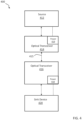
FIG. 1 , anoptical interconnect system 100 capable of supporting conversion of electrical signals to optical signals, and back to electrical signals is illustrated. Asignal source 112 is connected to anoptical transmitter 114 that acts as a first signal converter to convert electrical signals received from thesignal source 112 into optical signals. One or moreoptical fibers 115 are used to transfer optically encoded data to anoptical receiver 116. The optical receiver decodes and acts as a second signal converter to convert the data to electrical signals that are provided to asink device 120. Theoptical receiver 116 can include aseparate power module 118, which in at least one embodiment is connected viaelectrical power connection 119 to the sink device. - Various signaling protocols are supported by the optical interconnect system. In some embodiments, electrical signals can be provided in a first protocol by
source 112 and converted to a second protocol by theoptical receiver 116. In other embodiments, electrical signals can be provided in a first protocol bysource 112 and converted back to the same protocol by theoptical receiver 116. - In one particular embodiment, HDMI 1.4b/1.4, HDMI 2.0b/2.0, HDMI2.1, or other suitable HDMI protocols can be supported. HDMI 1.4b/1.4 supports 4K (3840 x 2160 pixels) video at 30 frames per second, while HDMI 2.0b/2.0 supports 4K video at 60 frames per second, with a bit rate of up to 18 Gbps. The latest HDMI 2.1 supports 8K video at 60 frames per second and 4K video at 120 frames per second, with a bit rate of up to 48 Gbps. HDMI is based on HDMI standard TMDS or FRL serial links for transmitting video and audio data. Typically, the HDMI interface is provided for transmitting digital television audiovisual signals from DVD players, game consoles, set-top boxes and other audiovisual source devices to other HDMI compatible devices, such as television sets, displays, projectors and other audiovisual devices. HDMI can also carry control and status information in both directions.
- In other embodiments, other connectors and protocols can be supported, including but not limited to serial or parallel connectors, Digital Video Interface (DVI), other suitable connectors such as those based on LVDS, DisplayPort, USB-C or SATA. In some embodiments, alternative encoding systems can be used. For example, TMDS serial links can be replaced with low density parity check (LDPC) code for video data. Alternatively, or in addition, a variable length and rate Reed-Solomon (RS) code can be used for audio and control information to provide error protection. Advantageously, such codes require no additional overhead for DC-balancing or transition minimization, resulting in an increased data rate as compared to TMDS encoded signals.
- In one embodiment,
source 112 can include, for example, DVD players, game consoles, smartphones, set-top boxes, telephones, computers, audio systems, or other network client devices.Source 112 can playback media data stored in a hard drive, a spinnable disk (e.g. Blu-ray or DVD), or held in solid state storage. In other embodiments, thesource 112 can receive data through wired or wireless connection to cable providers, satellite systems, or phone networks. Similarly,sink device 120 can also be televisions, monitors, displays, audio systems, projectors, or other network client devices. - In one embodiment, the
optical transmitter 114 can convert HDMI standard TMDS or FRL electrical signals using an optical conversion device connected to ground to reduce noise. Typically, this can be a laser diode driver (LDD). The optical conversion driver device can include an infrared or optical LED, semiconductor laser, or VCSEL device. - Advantageously, use of
optical fiber 115 and elimination of electrical wired connection both provides electrical isolation and greatly improved signal. Theoptical fiber 115 is well suited for using consumer or household environments, as well as in electrically active, wet, or moist environments such as are found in industrial, manufacturing, automobile, trucking, shipping, and avionics. In one embodiment, theoptical fiber 115 includes one or more multi-mode optical fibers protected by braided fiber or plastic sheathing or other suitable covering. If complete electrical isolation is not required, in another embodiment one or more low voltage electrical wires are also supported to provide power or control signals. - In one embodiment, the
optical receiver 116 can convert optical signals to HDMI standard TMDS or FRL or other suitable electrical signals. Theoptical receiver 116 can include a photo detector and an optical receiver that convert light impulses to an electrical signal. In some embodiments, a transimpedance amplifier (TIA) or other suitable signal amplification system can be used to increase signal power, and a PD (photodiode) or an APD (avalanche photodiode) can be used to convert optical signals to electrical currents. - Power from
power module 118 to operate theoptical receiver 116 can be provided by connection to thesink device 120, by connection to a second power port or another external power source (not shown), or by an internal battery source. In some embodiments, a sink device can support multiple connector types (HDMI, DisplayPort, USB, USB-C, DC power connector) that can be used as external secondary power sources and/or internal battery charging stations. In those embodiments that support source HDMI to sink HDMI connections, both power to operateoptical receiver 116 and additional power to emulate an electrical HDMI connection can be required since conventional HDMI connectable devices require a DC connection between thesource 112 and a groundedsink device 120 to complete the circuit. This DC connection creates a current return path from thesink device 120 to thesource 112. Since this connection is typically provided through internal shields covering the individual twisted wire pairs and a covering braid shield that are not available in a dedicated optical interconnect system, an additional power source is needed. -
FIG. 2 illustrates amethod 200 for interconnecting a source and a sink. Electrical signals from the source are converted to an optical signal (step 210) using a driver device for an infrared or optical LED, semiconductor laser, or VCSEL device. The optical signal is injected into a fiber optic cable and transferred (step 212). The transferred optical system is converted to an electrical signal (step 216) that is received by a sink (step 218). In order to ensure conversion of the electrical signal, plugging into the sink or connection to another external power source can supply power, wake signal conversion microprocessors or other electronics, and charge optional batteries (step 214). -
FIG. 3 illustrates an optical interconnect system with external power. In this embodiment asignal source 312 is connected to anoptical transmitter 314 that converts electrical signals received from thesignal source 312. One or moreoptical fibers 315 are used to transfer optically encoded data to anoptical receiver 316. The optical receiver decodes and converts the data to electrical signals that are provided to asink device 320. Theoptical receiver 316 can include aseparate power module 318, which in at least one embodiment is provided byelectrical power connection 319 to anexternal power module 322. In some embodiments the power module can be provided via other ports or power supplies on the sink device (e.g. a USB port), while in other embodiments power can be supplied by another device (e.g. a power over ethernet connection from a network switch) or a suitable direct power supply. -
FIG. 4 illustrates a bi-directionaloptical interconnect system 400 capable of supporting conversion of electrical signals to optical signals, and back to electrical signals. In a first direction of data transfer, signalsource 412 is connected to anoptical transceiver 414 that converts electrical signals received from thesignal source 412. One or moreoptical fibers 415 are used to transfer optically encoded data to anoptical transceiver 416. Theoptical transceiver 416 decodes and converts the data to electrical signals that are provided to asink device 420. A return signal from thesink device 420 tosource 412 is also supported. - Both the
optical transceiver separate power module power module 418 to thesink device 420. Similarly, an electrical power connection can be made to thesource device 412 from thepower module 419. - In one embodiment optical fiber can used for data transmission from the source device to the sink device. Additional optical fiber can be used for the transmission of a return signal from the
sink device 420 to thesource device 412. Such bi-directional signal functionality allows fuller support of the HDMI specification, including channels supporting low data-rate remote control commands, audio return from sink device to source, ethernet communication, and hot plug detection. Such data channels can include, but not limited to, a Consumer Electronics Control (CEC), an Audio Return Channel (ARC) or Enhanced Audio Return Channel (eARC), a HDMI Ethernet Channel (HEC) and a Hot Plug Detect (HPD). CEC allows a user to use a single remote to control multiple devices coupled together via HDMI cables. More specifically, a unique address is assigned to the connected group of devices, which is used for sending remote control commands to the devices.ARC or eARC is an audio link meant to replace other cables between sink device and source that allows source to reproduce the audio output from the sink device without using other cables. HEC enables IP-based applications over HDMI and provides a bidirectional Ethernet communication. HPD allows the source to sense the presence of sink device and reinitiates link if necessary. -
FIG. 5A illustrates one embodiment of HDMI optical fiberdata connection system 500 that includes electrical to optical, and subsequent optical to electrical conversion. This embodiment can substantially replace a conventional electrical HDMI interface having two identical connectors attached to opposite ends of a cable. Such cables typically include four shielded twisted pairs of copper wires and seven separate copper wires for communicating various information. Four of the shielded twisted wire pairs are adapted to communicate relatively high-speed data and clock in the form of Transition Minimized Differential Signaling (HDMI standard TMDS or FRL). In HDMI 2.0b and previous HDMI standards, three pairs are used for communicating video, audio, and auxiliary data, and are typically referred to as D0-D2. The last pair is used for transmitting a clock associated with the data, and is typically referred to as CLK. In HDMI 2.1, all four pairs are used for communicating video, audio and auxiliary data, and are typically referred to as D0-D3. The speed of the high-speed data may range from 3 to 12 gigabits per second (Gbps) per lane. The remaining seven separate wires are used for communicating relatively low-speed data, such as in the range of 100 kilobits per second (kbit/s) to 400 kbit/s. Two of such wires are referred to as Display Data Channel (DDC) for providing communication between devices using a communication channel that adheres to an I2C bus specification. One of the DDC wire pair, typically referred to as DDC DATA, is used to communicate data between the devices. The other DDC wire pair, typically referred to as DDC CLK, is used to transmit a clock associated with the data. The other five of the seven separate wires are CEC, utility, HPD, 5V power and ground. - In operation, the respective HDMI standard TMDS or FRL, DDC, and other electrical signals from
source 512 are provided to atransmitter 514 housed in an HDMI compatible connector. Using a laser diode driver (LDD) and a semiconductor laser or LED diode powered by voltage regulator REG1, an optical signal is generated and transferred to a photodetector and HDMI standard TMDS orFRL receiver 516 housed in another HDMI compatible connector. The HDMI standard TMDS or FRL receiver includes a transimpedance amplifier (TIA) connected to amplify the photodetector signal. The amplified electrical signals corresponding to the originally provided HDMI standard TMDS or FRL, DDC, and other electrical signals are sent to a television, display, or othersuitable sink 520. - In one embodiment, electrical power is supplied to the HDMI standard TMDS or FRL receiver through an electrical tap of the HDMI standard TMDS or FRL port by inductors L1 and L2 (or other suitable electrical filtering circuit element such as ferrite beads) connected to a voltage regulator (REG2). The voltage regulator REG2 is connected to ground to reduce noise and acts to convert the voltage to the required operating voltage or voltages for a transimpedance amplifier that receives optical signals and converts them to electrical signals.
- In some commercially available embodiments however, this mechanism will not work unassisted, since application of a specific voltage power is required to enable or otherwise trigger provision of power to the HDMI connection and connected electronics from
sink 520. - For embodiments that require power triggering of the HDMI connection, a rechargeable battery, supercapacitor, or similar charge bank can be used to supply an initial 5-volt charge via regulator (REG3) to the 5V pin on the HDMI port (RX5V) of the
sink 520. After triggering activation of the HDMI port, the electrical tap by inductors L1 and L2 (or other suitable electrical filtering circuit element such as ferrite beads) can be used to charge the battery or other power source. In operation, when the HDMI connector is not plugged into thesink 520, an enable pin "en" of REG3 is kept as open circuit and pulled to ground by resistor R4. Therefore, REG3 is turned off and thus does not draw current from the battery. When the HDMI connector is plugged into the sink 520 (e.g. a TV or display), the CEC pin or other appropriate pins, such as DDC, is connected to REG3 "en", which has certain voltage, e.g. 3.3V. REG3 is turned on and up-converts the battery voltage, e.g. 1.5V, to 5V. When the "5V" pin of thesink 520 is pulled to 5V, it starts to power the HDMI standard TMDS or FRL + and HDMI standard TMDS or FRL - ports. Inductors L1 and L2 block the AC signal provided by HDMI standard TMDS or FRL data connections and pass through the DC voltage (e.g. 2V) from HDMI standard TMDS or FRL ports to REG2 "in". REG2 up-converts or down-converts this voltage to the necessary voltage or voltages for the TIA to operate. Once REG2 starts to output a voltage, it switches the MUX input so that REG3 "in" is connected to REG2 "in". It also closes switch S1 and REG3 "out" starts to charge the battery. - Effectively, operation of the described circuit allows for the rechargeable battery supplying power to the 5V pin on the HDMI port of the sink 520 (RX5V) to be controlled to prevent battery dissipation when HDMI connector is unplugged. The rechargeable battery only operates when the cable is first plugged into the
sink 520. After thesink 520 starts to power the HDMI standard TMDS or FRL ports, the rechargeable battery stops output current and instead is switched into a recharge mode. - Alternatively,
FIG. 5B illustrates one embodiment of anoptical interconnect system 501 similar to that discussed with respect toFIG. 5A that converts HDMI standard TMDS or FRL signals to optical signals that includes a power tapping circuit without a battery. In operation, the respective HDMI standard TMDS or FRL, DDC, and other electrical signals fromsource 513 are provided to atransmitter 515 housed in an HDMI compatible connector. Using a laser diode driver (LDD) and a semiconductor laser or LED diode powered by voltage regulator REG1, an optical signal is generated and transferred to a photodetector and HDMI standard TMDS orFRL receiver 517 housed in another HDMI compatible connector. The HDMI standard TMDS or FRL receiver includes a transimpedance amplifier (TIA) connected to amplify the photodetector signal. The amplified electrical signals corresponding to the originally provided HDMI standard TMDS or FRL, DDC, and other electrical signals are sent to a television, display, or othersuitable sink 521. In addition, the described circuit includes a slew rate controller to control ramp up time of current draw of REG2 from the power taps on the high speed differential signal RX_Data[3:0]. If this ramp up time is too short, the DC voltage on RX _Data[3:0] can drop to such a low level that REG2 stops working. This is prevented by the slew rate controller regulating the ramp up time to be slow enough to ensure the proper power tapping on RX_Data[3:0]. -
FIG. 5C illustrates one embodiment of anoptical interconnect system 550 that converts both HDMI standard TMDS or FRL and control or other non- HDMI standard TMDS or FRL signals to optical signals. HDMI protocol requires bi-directional communication channels betweensource 552 and sink 554 for successful video/audio transmission and reception, which include but not limited to CEC, Utility, DDC (SCL), DDC (SDA), Ground, 5V Power and HPD. In the embodiment ofFIG. 5B , all communication channels betweensource 552 and sink 554 are aggregated onto two optical fibers. Anoptical fiber 561 carries data fromsource 552 to sink 554, while anoptical fiber 562 carries data fromsink 554 tosource 552, thus establishing bidirectional communication. Digital signal processing are realized by Digital Encoder/Decoder 1 (DED1 556) on the source side and Digital Encoder/Decoder 2 (DED 558) on the sink side.DED1 Fig 5B operates in a manner similar toREG 1 as seen inFIG. 5A . P1, N1 and R5 form a transimpedance amplifier that is powered by REG1 "out" and buffers a photodetector's output into DED1. Similarly, P4 is a current source that is powered by REG2 "out" and modulated by DED2 and drives a VCSEL or LED diode. REG2 inFIG. 5B operates in a manner similar to REG2 as seen inFIG. 5A that utilizes inductive power tapping from the HDMI standard TMDS or FRL ports. P3, N3 and R6 form a transimpedance amplifier that is powered by REG2 "out" and buffers a photodetector's output into DED2. In this embodiment, multiple HDMI communication channels are replicated on both source and sink sides using only two optical fibers. -
FIG. 6A illustrates one embodiment of a HDMI compatible fullyoptical interconnect system 600. As illustrated, multiple multi-modeoptical fiber cables transmitter 602 to areceiver 604, and at least one multi-modeoptical fiber 614 that transmits signals back from thereceiver 604 to thetransmitter 602. In thetransmitter 602, electrical HDMI standard TMDS or FRL and non-HDMI standard TMDS or FRL data are converted to optical pulses using VCSEL laser or LED diodes. A photodetector and associated circuits are used to convert received optical pulses fromoptical fiber 614 to electrical signals that can be processed by a connected source (not shown). Thereceiver 604 has multiple photodetectors and respectively connected HDMI standard TMDS or FRL optoelectronic transmitters to convert received optical pulses fromoptical fiber receiver 604 also includes a VCSEL laser or LED diode connected to an encoder/decoder to convert electrical signals to optical signals that can be sent to thetransmitter 602. -
FIG. 6B illustrates one embodiment of a HDMI compatible hybrid electrical andoptical interconnect system 620. As illustrated, multiple multi-modeoptical fiber cables 630 are used to transmit data from atransmitter 622 to areceiver 624. In thetransmitter 622, electrical HDMI standard TMDS or FRL data is converted to optical pulses using VCSEL laser or other laser diodes. A photodetector and associated circuits are used to convert received optical pulses fromoptical fiber 634 to electrical signals that can be processed by a connected source (not shown). Thereceiver 624 has multiple photodetectors and respectively connected HDMI standard TMDS or FRL optoelectronic transmitters to convert received optical pulses fromoptical fiber 630 to electrical signals that can be processed by a connected sink (not shown). In addition to the optical connections, thesystem 620 also supports electricalwired connection 632 for various control and data signals. As will be understood, these connections can be unidirectional or bidirectional betweentransmitter 622 andreceiver 624. In addition, the system includes anelectrical power connection 634 connecting respective power management units oftransmitter 622 andreceiver 624. Advantageously, because power is available, power triggering of the HDMI connection and their associated electronics and battery systems such as described with respect to the embodiment illustrated inFIG. 5 are not necessary. -
FIG. 6C illustrates all optical data connections and an electrical power connection for an HDMIcompatible interconnect system 640. As illustrated, multiple multi-modeoptical fiber cables transmitter 642 to areceiver 644, and as well as at least one multi-mode optical fiber 656 that transmits signals back from thereceiver 644 to thetransmitter 642. In thetransmitter 642, electrical HDMI standard TMDS or FRL data is converted to optical pulses using VCSEL laser or LED diodes. Thereceiver 644 has multiple photodetectors and respectively connected HDMI standard TMDS or FRL optoelectronic transmitters to convert received optical pulses fromoptical fiber receiver 644 also includes a VCSEL laser or LED diode connected to an encoder/decoder to convert electrical signals to optical signals that can be sent to thetransmitter 642 along multi-mode optical fiber 656. In addition, the system includes anelectrical power connection 654 connectingtransmitter 642 andreceiver 644. Advantageously, because power is available, power triggering of the HDMI connection and their associated electronics and battery systems such as described with respect to the embodiment illustrated inFIG. 5 are not necessary. However, in certain embodiments, a power tap on HDMI standard TMDS or FRL ports (e.g. using inductors and regulators) can still be used to power the HDMI standard TMDS or FRL receiver or other associated circuitry. -
FIG. 7 illustrates one embodiment of a HDMIcompatible interconnect system 700 including bundled and loosely loopedoptical cables 702, andsource 710 and sink 712 HDMI connectors.Signal converters respective HDMI connector - As will be understood, the system and methods described herein can operate for interaction with devices such as servers, desktop computers, laptops, tablets, game consoles, or smart phones. Data and control signals can be received, generated, or transported between varieties of external data sources, including wireless networks, personal area networks, cellular networks, the Internet, or cloud mediated data sources. In addition, sources of local data (e.g. a hard drive, solid state drive, flash memory, or any other suitable memory, including dynamic memory, such as SRAM or DRAM) that can allow for local data storage of user-specified preferences or protocols.
- Many modifications and other embodiments of the invention will come to the mind of one skilled in the art having the benefit of the teachings presented in the foregoing descriptions and the associated drawings. Therefore, it is understood that the invention is not to be limited to the specific embodiments disclosed. It is also understood that other embodiments of this invention may be practiced in the absence of an element/step not specifically disclosed herein.
Claims (14)
- A battery triggered optical data interconnect system for electro-optical HDMI signal communication between an HDMI source and an HDMI sink, comprising:a first HDMI compatible electrical connector (710) configured to receive HDMI electrical signals from the source;a first signal converter (720) connected to the first HDMI compatible electrical connector and including electronics for conversion of differential electrical signals to optical signals, with the electronics including an optical conversion device;at least one optical fiber connected to the first signal converter;a second signal converter (722) connected to the at least one optical fiber and including electronics for conversion of optical signals to differential electrical signals, the electronics including differential circuitry that further includes an electric signal amplifier;a power module for the second signal converter including a power tap connected to the differential circuitry and a first voltage regulator (REG2) connected to the power tap to provide power to the electrical signal amplifier;a rechargeable battery module configured to trigger HDMI power activation of connected HDMI differential electrical data ports, the battery module being connected to the power tap; anda second HDMI compatible electrical connector (712) connected to the second signal converter and configured to send the differential electrical data as HDMI differential data signals to the sink.
- The optical data interconnect system of claim 1 wherein the optical conversion device is a laser device driver (LDD), and wherein the at least one optical fiber is a multi-mode optical fiber.
- The optical data interconnect system of claim 1 wherein the first HDMI compatible electrical connector is able to transmit control or other signals from the source to the sink using at least one of an electrical and an optical connection to the second HDMI compatible electrical connector and the second HDMI compatible electrical connector is able to transmit control or other signals from the sink to the source using at least one of an electrical and an optical connection to the first HDMI compatible electrical connector.
- The optical data interconnect system of claim 1 wherein the electrical signal amplifier of the second signal converter further comprises a transimpedance amplifier (TIA).
- The optical data interconnect system of claim 1 wherein the first signal converter connected to the first HDMI compatible electrical connector and the second signal converter connected to the second HDMI compatible electrical connector each comprises a photodetector, a VCSEL laser or LED diode and encoder/decoder to receive and transmit optical signals.
- The optical data interconnect system of claim 1 wherein the rechargeable battery module further comprises a second voltage regulator (REG3) to supply 5 volts to the 5V pin on the HDMI port.
- The optical data interconnect system of claim 1 wherein the rechargeable battery module is disconnected from the second voltage regulator after power is received from the power tap, wherein the rechargeable battery module is recharged by the power tap.
- A method for operating an optical data interconnect system for electro-optical HDMI signal communication between an HDMI source and an HDMI sink, comprising the steps of:providing a first HDMI compatible electrical connector (710) configured to receive electrical signals from the source;converting differential signals to optical signals using a first signal converter (720) connected to the first HDMI compatible electrical connector, the first signal converter including an optical conversion device;sending optical signals along at least one optical fiber connected to the first signal converter;receiving optical signals and converting them to differential electrical signals using electronics in a second signal converter (722) connected to the at least one optical fiber, the electronics further including differential circuitry that further includes an electric signal amplifier;powering the second signal converter using a power module having a power tap connected to the differential circuitry and using a first voltage regulator (REG2) connected to the power tap to provide power to the electrical signal amplifier;using a rechargeable battery module configured to trigger HDMI power activation of connected HDMI differential electrical data ports, the battery module being connected to the power tap; andproviding a second HDMI compatible electrical connector (712) connected to the second signal converter and configured to send the HDMI differential electrical data as HDMI differential data signals to the sink.
- The optical data interconnect operating method of claim 8 wherein the optical conversion device is a laser device driver (LDD) , and wherein the at least one optical fiber is a multi-mode optical fiber.
- The optical data interconnect operating method of claim 8 wherein the first HDMI compatible electrical connector is able to transmit control or other signals from the source to the sink using at least one of an electrical and an optical connection to the second HDMI compatible electrical connector and the second HDMI compatible electrical connector is able to transmit control or other signals from the sink to the source using at least one of an electrical and an optical connection to the first HDMI compatible electrical connector.
- The optical data interconnect operating method of claim 8 wherein the electrical signal amplifier of the second signal converter further comprises a transimpedance amplifier (TIA).
- The optical data interconnect operating method of claim 8 wherein the first signal converter connected to the first HDMI compatible electrical connector and the second signal converter connected to the second HDMI compatible electrical connector each-comprises a photodetector, a VCSEL laser or LED diode and encoder/decoder to receive and transmit optical signals.
- The optical data interconnect operating method of claim 8 wherein the rechargeable battery module further comprises a second voltage regulator (REG3) to supply 5 volts to a 5V pin on a HDMI port.
- The optical data interconnect operating method of claim 8 wherein the rechargeable battery module is disconnected from the second voltage regulator after power is received from the power tap, and wherein the rechargeable battery module is recharged by the power tap.
Applications Claiming Priority (2)
| Application Number | Priority Date | Filing Date | Title |
|---|---|---|---|
| US201962817286P | 2019-03-12 | 2019-03-12 | |
| PCT/IB2020/000209 WO2020183242A1 (en) | 2019-03-12 | 2020-03-12 | Battery triggering for activation of an optical data interconnect system |
Publications (3)
| Publication Number | Publication Date |
|---|---|
| EP3939250A1 EP3939250A1 (en) | 2022-01-19 |
| EP3939250A4 EP3939250A4 (en) | 2022-12-21 |
| EP3939250B1 true EP3939250B1 (en) | 2024-11-27 |
Family
ID=68772842
Family Applications (1)
| Application Number | Title | Priority Date | Filing Date |
|---|---|---|---|
| EP20770551.8A Active EP3939250B1 (en) | 2019-03-12 | 2020-03-12 | Battery triggering for activation of an optical data interconnect system |
Country Status (6)
| Country | Link |
|---|---|
| US (1) | US11233581B2 (en) |
| EP (1) | EP3939250B1 (en) |
| JP (1) | JP7477524B2 (en) |
| KR (1) | KR102799162B1 (en) |
| CN (1) | CN110572602B (en) |
| WO (1) | WO2020183242A1 (en) |
Families Citing this family (19)
| Publication number | Priority date | Publication date | Assignee | Title |
|---|---|---|---|---|
| US20220109906A1 (en) * | 2019-03-12 | 2022-04-07 | Wingcomm Co. Ltd. | Optical Data Interconnect System |
| US20220109500A1 (en) * | 2019-03-12 | 2022-04-07 | Wingcomm Co. Ltd. | Optical Data Interconnect System |
| CN110572602B (en) | 2019-03-12 | 2021-10-15 | 飞昂创新科技南通有限公司 | Activated battery triggering for optical data interconnect systems |
| CN110661991A (en) * | 2019-03-12 | 2020-01-07 | 飞昂创新科技南通有限公司 | Target Powered Optical Data Interconnect System |
| US20220109510A1 (en) * | 2019-03-12 | 2022-04-07 | WINGCOMM Co, Ltd. | Optical Data Interconnect System |
| CN113079407B (en) * | 2020-01-06 | 2023-01-10 | 瑞昱半导体股份有限公司 | Data packing circuit and data packing method |
| US20210219016A1 (en) * | 2020-01-15 | 2021-07-15 | Luca Zanetti | Fiber optic based hdmi cable added with integrated ir infrared remote control without reducing hdmi connections and standard specs |
| US11320599B2 (en) * | 2021-01-15 | 2022-05-03 | Luca Zanetti | Multimedia connector cable |
| US11573385B1 (en) * | 2021-04-07 | 2023-02-07 | Luca Zanetti | Multimedia connector cable |
| TWI771132B (en) * | 2021-05-26 | 2022-07-11 | 宏觀微電子股份有限公司 | A source node architecture for an optical communication channel |
| CN115695739B (en) * | 2021-07-28 | 2025-04-29 | 光程研创股份有限公司 | Optical Communication Interface System |
| CN114884573A (en) * | 2021-11-15 | 2022-08-09 | 国网新源控股有限公司 | Single-mode fiber-based trigger signal transmission device and method |
| WO2023111874A1 (en) * | 2021-12-16 | 2023-06-22 | Wingcomm Co. Ltd. | Optical data interconnect system |
| WO2023111872A1 (en) * | 2021-12-16 | 2023-06-22 | Wingcomm Co. Ltd. | Optical data interconnect system |
| WO2023111875A1 (en) * | 2021-12-16 | 2023-06-22 | Wingcomm Co. Ltd. | Optical data interconnect system |
| WO2023111876A1 (en) * | 2021-12-16 | 2023-06-22 | Wingcomm Co. Ltd. | Optical data interconnect system |
| WO2023210160A1 (en) * | 2022-04-25 | 2023-11-02 | ソニーグループ株式会社 | Transmission device, reception device, and transmission/reception system |
| US12028116B2 (en) * | 2022-06-24 | 2024-07-02 | Celerity Technologies Inc. | HDMI matrix switcher receiving side and receiver-side fiber connector power management |
| CN115980706B (en) * | 2023-01-09 | 2025-08-12 | 香港科技大学(广州) | Automobile, battery index and distance detection method thereof, controller and storage medium |
Family Cites Families (40)
| Publication number | Priority date | Publication date | Assignee | Title |
|---|---|---|---|---|
| FR2556105B1 (en) | 1983-12-02 | 1986-08-29 | Thomson Csf | OPTICAL TRANSMISSION CHANNEL WITH ELECTRICAL CONNECTORS |
| KR100402409B1 (en) * | 2001-05-26 | 2003-10-30 | (주)오피트정보통신 | Digital Vidio Signal Interface Module For Transmitting Long Distance |
| JP4569195B2 (en) * | 2003-11-14 | 2010-10-27 | 富士ゼロックス株式会社 | Signal transmission device |
| US20060083518A1 (en) * | 2004-10-14 | 2006-04-20 | Myunghee Lee | Fiber optic connection for digital displays |
| JP4193067B2 (en) * | 2005-04-28 | 2008-12-10 | 住友電気工業株式会社 | Optical DVI cable and optical signal transmission device |
| US20060280055A1 (en) * | 2005-06-08 | 2006-12-14 | Miller Rodney D | Laser power control and device status monitoring for video/graphic applications |
| US7331819B2 (en) * | 2005-07-11 | 2008-02-19 | Finisar Corporation | Media converter |
| US7729618B2 (en) * | 2005-08-30 | 2010-06-01 | Finisar Corporation | Optical networks for consumer electronics |
| WO2007098411A2 (en) * | 2006-02-17 | 2007-08-30 | Standard Microsystems Corporation | Transmission network having an optical receiver that utilizes dual power pins and a single status pin to lower power consumption, lower manufacturing cost, and increase transmission efficiency |
| US7912381B2 (en) | 2006-06-02 | 2011-03-22 | Standard Microsystems Corporation | Transmission network having an optical receiver that utilizes dual power pins and a single status pin to lower power consumption, lower manufacturing cost, and increase transmission efficiency |
| JP2007300490A (en) * | 2006-05-01 | 2007-11-15 | Sony Corp | Digital video transmission apparatus, digital video reception apparatus, digital video transmission system, and digital video transmission method |
| TW200803168A (en) * | 2006-06-14 | 2008-01-01 | Realtek Semiconductor Corp | Circuit and method for controlling the slew rate of output voltage |
| KR100861769B1 (en) * | 2007-06-07 | 2008-10-06 | 옵티시스 주식회사 | Digital video transmission system for transmitting digital video data |
| US8169196B2 (en) * | 2007-06-27 | 2012-05-01 | Sony Mobile Communications Ab | Charging device |
| US20110129229A1 (en) * | 2008-07-26 | 2011-06-02 | FOCE Technology Internatioal BV | Optical receiver device |
| WO2010040816A2 (en) * | 2008-10-09 | 2010-04-15 | Silicon Line Gmbh | Circuit arrangement and method for transmitting tmds encoded signals |
| US8370536B2 (en) | 2009-04-24 | 2013-02-05 | Analog Devices, Inc. | Method and apparatus for providing robust display digital channel transmission |
| US8340529B2 (en) * | 2009-06-13 | 2012-12-25 | Kalpendu Shastri | HDMI TMDS optical signal transmission using PAM technique |
| CN101931466A (en) * | 2009-06-22 | 2010-12-29 | 钱国涛 | Method for extending HDMI or DVI interface connection at ultra-long distance by using five optical fibers |
| US20110121656A1 (en) | 2009-11-20 | 2011-05-26 | Freescale Semiconductor, Inc. | Systems and methods for delivering power in response to a connection event |
| US20110121655A1 (en) | 2009-11-24 | 2011-05-26 | Clement Liu | Inverter with uninterruptible power supply for water pump |
| JP4898948B1 (en) * | 2010-09-10 | 2012-03-21 | 株式会社フジクラ | Data transmission device, data transmission method, and data transmission device control program |
| JP5611866B2 (en) * | 2011-03-09 | 2014-10-22 | 日立コンシューマエレクトロニクス株式会社 | Transmission system and relay device |
| PL2710691T3 (en) * | 2011-05-17 | 2017-01-31 | 3M Innovative Properties Company | Remote socket apparatus |
| US8948197B2 (en) * | 2011-09-28 | 2015-02-03 | Cosemi Technologies, Inc. | System and method for communicating optical signals via communication cable medium |
| CN103283221B (en) * | 2011-12-27 | 2016-03-16 | 松下知识产权经营株式会社 | Communication Cable |
| US9160451B2 (en) * | 2012-03-06 | 2015-10-13 | Sae Magnetics (H.K.) Ltd. | Active optical cable connector plug and active optical cable using same |
| US9348383B2 (en) * | 2013-03-01 | 2016-05-24 | Intel Corporation | Apparatus for starting up switching voltage regulator |
| US9397750B2 (en) * | 2013-07-03 | 2016-07-19 | Cosemi Technologies, Inc. | Hybrid electrical-optical data communications cable with wireline capacitance compensation |
| JP6231954B2 (en) * | 2014-07-23 | 2017-11-15 | 株式会社フジクラ | Image transmission / reception system, active cable monitoring method, active cable control method, image transmission device, image reception device, and active cable |
| KR102613489B1 (en) * | 2016-05-27 | 2023-12-14 | 삼성전자주식회사 | Method for controlling charge for improving receive sensitivity and electronic device for the same |
| US10943558B2 (en) * | 2016-06-30 | 2021-03-09 | Intel Corporation | EDP MIPI DSI combination architecture |
| CN106130645A (en) * | 2016-07-01 | 2016-11-16 | 武汉博昇光电股份有限公司 | A kind of ultra high-definition distance HDMI optical cable |
| JP6873814B2 (en) * | 2017-05-11 | 2021-05-19 | 株式会社東芝 | Cables and electronics |
| US20200233166A1 (en) * | 2017-05-29 | 2020-07-23 | Fujikura Ltd. | Active optical cable, method of controlling active optical cable, and method of wiring active optical cable |
| CN208158594U (en) * | 2018-04-26 | 2018-11-27 | 白昀 | A kind of photelectric receiver suitable for active optical cable |
| US10241283B1 (en) * | 2018-04-30 | 2019-03-26 | Sure-Fire Electrical Corporation | Signal transmission cable with HDMI connectors |
| CN108964767A (en) * | 2018-09-05 | 2018-12-07 | 深圳智尚视讯科技有限公司 | A kind of HDMI wire transmitted using optical fiber |
| CN110572602B (en) * | 2019-03-12 | 2021-10-15 | 飞昂创新科技南通有限公司 | Activated battery triggering for optical data interconnect systems |
| CN110572625B (en) * | 2019-03-12 | 2022-03-18 | 飞昂创新科技南通有限公司 | Optical Data Interconnect System |
-
2019
- 2019-04-04 CN CN201910269968.7A patent/CN110572602B/en active Active
-
2020
- 2020-03-12 JP JP2021555101A patent/JP7477524B2/en active Active
- 2020-03-12 US US16/817,335 patent/US11233581B2/en active Active
- 2020-03-12 KR KR1020217031208A patent/KR102799162B1/en active Active
- 2020-03-12 EP EP20770551.8A patent/EP3939250B1/en active Active
- 2020-03-12 WO PCT/IB2020/000209 patent/WO2020183242A1/en not_active Ceased
Also Published As
| Publication number | Publication date |
|---|---|
| EP3939250A4 (en) | 2022-12-21 |
| KR20210148147A (en) | 2021-12-07 |
| US11233581B2 (en) | 2022-01-25 |
| US20200295846A1 (en) | 2020-09-17 |
| EP3939250A1 (en) | 2022-01-19 |
| CN110572602A (en) | 2019-12-13 |
| JP2022524633A (en) | 2022-05-09 |
| WO2020183242A1 (en) | 2020-09-17 |
| KR102799162B1 (en) | 2025-04-21 |
| JP7477524B2 (en) | 2024-05-01 |
| CN110572602B (en) | 2021-10-15 |
Similar Documents
| Publication | Publication Date | Title |
|---|---|---|
| EP3939250B1 (en) | Battery triggering for activation of an optical data interconnect system | |
| US11233569B2 (en) | Optical data interconnect system | |
| US11233570B2 (en) | Sink powered optical data interconnect system | |
| US20220337318A1 (en) | Optical Data Interconnect System | |
| US8180225B2 (en) | Optical data link | |
| US6585431B1 (en) | Noncontact information transmitter | |
| US20210314656A1 (en) | HDMI Apparatus Using Optical Communication | |
| CN109587427A (en) | High-definition multimedia interface active optical cable circuit | |
| US20220109500A1 (en) | Optical Data Interconnect System | |
| WO2023111873A1 (en) | Optical data interconnect system | |
| CN109994281A (en) | A kind of AOC cable of the compatible multiplex roles of energy | |
| WO2023040553A1 (en) | Communication device, communication system and optical module | |
| US8878590B2 (en) | Techniques for switching between AC-coupled connectivity and DC-coupled connectivity | |
| US20220109906A1 (en) | Optical Data Interconnect System | |
| US20220109510A1 (en) | Optical Data Interconnect System | |
| US20220329900A1 (en) | Optical Data Interconnect System | |
| WO2023111876A1 (en) | Optical data interconnect system | |
| WO2023111872A1 (en) | Optical data interconnect system | |
| WO2023111874A1 (en) | Optical data interconnect system | |
| WO2023111875A1 (en) | Optical data interconnect system | |
| KR101857980B1 (en) | High Speed Active Optical Cable | |
| CN210518603U (en) | System for detecting transmission state of high-definition video image | |
| US20140051281A1 (en) | Passive Cable Adaptor With Battery Charging Capability | |
| CN203561773U (en) | an audio-visual connector | |
| CN223402530U (en) | An all-optical transmission component for HDMI |
Legal Events
| Date | Code | Title | Description |
|---|---|---|---|
| STAA | Information on the status of an ep patent application or granted ep patent |
Free format text: STATUS: THE INTERNATIONAL PUBLICATION HAS BEEN MADE |
|
| PUAI | Public reference made under article 153(3) epc to a published international application that has entered the european phase |
Free format text: ORIGINAL CODE: 0009012 |
|
| STAA | Information on the status of an ep patent application or granted ep patent |
Free format text: STATUS: REQUEST FOR EXAMINATION WAS MADE |
|
| 17P | Request for examination filed |
Effective date: 20211012 |
|
| AK | Designated contracting states |
Kind code of ref document: A1 Designated state(s): AL AT BE BG CH CY CZ DE DK EE ES FI FR GB GR HR HU IE IS IT LI LT LU LV MC MK MT NL NO PL PT RO RS SE SI SK SM TR |
|
| DAV | Request for validation of the european patent (deleted) | ||
| DAX | Request for extension of the european patent (deleted) | ||
| A4 | Supplementary search report drawn up and despatched |
Effective date: 20221118 |
|
| RIC1 | Information provided on ipc code assigned before grant |
Ipc: H04B 10/25 20130101ALI20221114BHEP Ipc: H03F 3/08 20060101ALI20221114BHEP Ipc: H04B 10/80 20130101ALI20221114BHEP Ipc: H03F 3/45 20060101ALI20221114BHEP Ipc: H04N 5/765 20060101AFI20221114BHEP |
|
| RIC1 | Information provided on ipc code assigned before grant |
Ipc: H04B 10/25 20130101ALI20230627BHEP Ipc: H03F 3/08 20060101ALI20230627BHEP Ipc: H04B 10/80 20130101ALI20230627BHEP Ipc: H03F 3/45 20060101ALI20230627BHEP Ipc: H04N 5/765 20060101AFI20230627BHEP |
|
| STAA | Information on the status of an ep patent application or granted ep patent |
Free format text: STATUS: EXAMINATION IS IN PROGRESS |
|
| 17Q | First examination report despatched |
Effective date: 20230926 |
|
| GRAP | Despatch of communication of intention to grant a patent |
Free format text: ORIGINAL CODE: EPIDOSNIGR1 |
|
| STAA | Information on the status of an ep patent application or granted ep patent |
Free format text: STATUS: GRANT OF PATENT IS INTENDED |
|
| INTG | Intention to grant announced |
Effective date: 20240618 |
|
| GRAS | Grant fee paid |
Free format text: ORIGINAL CODE: EPIDOSNIGR3 |
|
| GRAA | (expected) grant |
Free format text: ORIGINAL CODE: 0009210 |
|
| STAA | Information on the status of an ep patent application or granted ep patent |
Free format text: STATUS: THE PATENT HAS BEEN GRANTED |
|
| AK | Designated contracting states |
Kind code of ref document: B1 Designated state(s): AL AT BE BG CH CY CZ DE DK EE ES FI FR GB GR HR HU IE IS IT LI LT LU LV MC MK MT NL NO PL PT RO RS SE SI SK SM TR |
|
| P01 | Opt-out of the competence of the unified patent court (upc) registered |
Free format text: CASE NUMBER: APP_57376/2024 Effective date: 20241021 |
|
| REG | Reference to a national code |
Ref country code: GB Ref legal event code: FG4D |
|
| REG | Reference to a national code |
Ref country code: CH Ref legal event code: EP |
|
| REG | Reference to a national code |
Ref country code: IE Ref legal event code: FG4D |
|
| REG | Reference to a national code |
Ref country code: DE Ref legal event code: R096 Ref document number: 602020042103 Country of ref document: DE |
|
| REG | Reference to a national code |
Ref country code: LT Ref legal event code: MG9D |
|
| REG | Reference to a national code |
Ref country code: NL Ref legal event code: MP Effective date: 20241127 |
|
| PG25 | Lapsed in a contracting state [announced via postgrant information from national office to epo] |
Ref country code: PT Free format text: LAPSE BECAUSE OF FAILURE TO SUBMIT A TRANSLATION OF THE DESCRIPTION OR TO PAY THE FEE WITHIN THE PRESCRIBED TIME-LIMIT Effective date: 20250327 Ref country code: HR Free format text: LAPSE BECAUSE OF FAILURE TO SUBMIT A TRANSLATION OF THE DESCRIPTION OR TO PAY THE FEE WITHIN THE PRESCRIBED TIME-LIMIT Effective date: 20241127 Ref country code: IS Free format text: LAPSE BECAUSE OF FAILURE TO SUBMIT A TRANSLATION OF THE DESCRIPTION OR TO PAY THE FEE WITHIN THE PRESCRIBED TIME-LIMIT Effective date: 20250327 |
|
| PGFP | Annual fee paid to national office [announced via postgrant information from national office to epo] |
Ref country code: DE Payment date: 20250331 Year of fee payment: 6 |
|
| PG25 | Lapsed in a contracting state [announced via postgrant information from national office to epo] |
Ref country code: NL Free format text: LAPSE BECAUSE OF FAILURE TO SUBMIT A TRANSLATION OF THE DESCRIPTION OR TO PAY THE FEE WITHIN THE PRESCRIBED TIME-LIMIT Effective date: 20241127 Ref country code: FI Free format text: LAPSE BECAUSE OF FAILURE TO SUBMIT A TRANSLATION OF THE DESCRIPTION OR TO PAY THE FEE WITHIN THE PRESCRIBED TIME-LIMIT Effective date: 20241127 |
|
| REG | Reference to a national code |
Ref country code: AT Ref legal event code: MK05 Ref document number: 1746858 Country of ref document: AT Kind code of ref document: T Effective date: 20241127 |
|
| PG25 | Lapsed in a contracting state [announced via postgrant information from national office to epo] |
Ref country code: BG Free format text: LAPSE BECAUSE OF FAILURE TO SUBMIT A TRANSLATION OF THE DESCRIPTION OR TO PAY THE FEE WITHIN THE PRESCRIBED TIME-LIMIT Effective date: 20241127 |
|
| PG25 | Lapsed in a contracting state [announced via postgrant information from national office to epo] |
Ref country code: ES Free format text: LAPSE BECAUSE OF FAILURE TO SUBMIT A TRANSLATION OF THE DESCRIPTION OR TO PAY THE FEE WITHIN THE PRESCRIBED TIME-LIMIT Effective date: 20241127 |
|
| PG25 | Lapsed in a contracting state [announced via postgrant information from national office to epo] |
Ref country code: NO Free format text: LAPSE BECAUSE OF FAILURE TO SUBMIT A TRANSLATION OF THE DESCRIPTION OR TO PAY THE FEE WITHIN THE PRESCRIBED TIME-LIMIT Effective date: 20250227 |
|
| PG25 | Lapsed in a contracting state [announced via postgrant information from national office to epo] |
Ref country code: GR Free format text: LAPSE BECAUSE OF FAILURE TO SUBMIT A TRANSLATION OF THE DESCRIPTION OR TO PAY THE FEE WITHIN THE PRESCRIBED TIME-LIMIT Effective date: 20250228 Ref country code: AT Free format text: LAPSE BECAUSE OF FAILURE TO SUBMIT A TRANSLATION OF THE DESCRIPTION OR TO PAY THE FEE WITHIN THE PRESCRIBED TIME-LIMIT Effective date: 20241127 Ref country code: LV Free format text: LAPSE BECAUSE OF FAILURE TO SUBMIT A TRANSLATION OF THE DESCRIPTION OR TO PAY THE FEE WITHIN THE PRESCRIBED TIME-LIMIT Effective date: 20241127 |
|
| PG25 | Lapsed in a contracting state [announced via postgrant information from national office to epo] |
Ref country code: PL Free format text: LAPSE BECAUSE OF FAILURE TO SUBMIT A TRANSLATION OF THE DESCRIPTION OR TO PAY THE FEE WITHIN THE PRESCRIBED TIME-LIMIT Effective date: 20241127 |
|
| PG25 | Lapsed in a contracting state [announced via postgrant information from national office to epo] |
Ref country code: RS Free format text: LAPSE BECAUSE OF FAILURE TO SUBMIT A TRANSLATION OF THE DESCRIPTION OR TO PAY THE FEE WITHIN THE PRESCRIBED TIME-LIMIT Effective date: 20250227 |
|
| PG25 | Lapsed in a contracting state [announced via postgrant information from national office to epo] |
Ref country code: SM Free format text: LAPSE BECAUSE OF FAILURE TO SUBMIT A TRANSLATION OF THE DESCRIPTION OR TO PAY THE FEE WITHIN THE PRESCRIBED TIME-LIMIT Effective date: 20241127 |
|
| PG25 | Lapsed in a contracting state [announced via postgrant information from national office to epo] |
Ref country code: DK Free format text: LAPSE BECAUSE OF FAILURE TO SUBMIT A TRANSLATION OF THE DESCRIPTION OR TO PAY THE FEE WITHIN THE PRESCRIBED TIME-LIMIT Effective date: 20241127 |
|
| PG25 | Lapsed in a contracting state [announced via postgrant information from national office to epo] |
Ref country code: EE Free format text: LAPSE BECAUSE OF FAILURE TO SUBMIT A TRANSLATION OF THE DESCRIPTION OR TO PAY THE FEE WITHIN THE PRESCRIBED TIME-LIMIT Effective date: 20241127 |
|
| PG25 | Lapsed in a contracting state [announced via postgrant information from national office to epo] |
Ref country code: RO Free format text: LAPSE BECAUSE OF FAILURE TO SUBMIT A TRANSLATION OF THE DESCRIPTION OR TO PAY THE FEE WITHIN THE PRESCRIBED TIME-LIMIT Effective date: 20241127 |
|
| PG25 | Lapsed in a contracting state [announced via postgrant information from national office to epo] |
Ref country code: SK Free format text: LAPSE BECAUSE OF FAILURE TO SUBMIT A TRANSLATION OF THE DESCRIPTION OR TO PAY THE FEE WITHIN THE PRESCRIBED TIME-LIMIT Effective date: 20241127 |
|
| PG25 | Lapsed in a contracting state [announced via postgrant information from national office to epo] |
Ref country code: CZ Free format text: LAPSE BECAUSE OF FAILURE TO SUBMIT A TRANSLATION OF THE DESCRIPTION OR TO PAY THE FEE WITHIN THE PRESCRIBED TIME-LIMIT Effective date: 20241127 |
|
| PG25 | Lapsed in a contracting state [announced via postgrant information from national office to epo] |
Ref country code: IT Free format text: LAPSE BECAUSE OF FAILURE TO SUBMIT A TRANSLATION OF THE DESCRIPTION OR TO PAY THE FEE WITHIN THE PRESCRIBED TIME-LIMIT Effective date: 20241127 |
|
| REG | Reference to a national code |
Ref country code: DE Ref legal event code: R097 Ref document number: 602020042103 Country of ref document: DE |
|
| PG25 | Lapsed in a contracting state [announced via postgrant information from national office to epo] |
Ref country code: SE Free format text: LAPSE BECAUSE OF FAILURE TO SUBMIT A TRANSLATION OF THE DESCRIPTION OR TO PAY THE FEE WITHIN THE PRESCRIBED TIME-LIMIT Effective date: 20241127 |
|
| PLBE | No opposition filed within time limit |
Free format text: ORIGINAL CODE: 0009261 |
|
| STAA | Information on the status of an ep patent application or granted ep patent |
Free format text: STATUS: NO OPPOSITION FILED WITHIN TIME LIMIT |
|
| REG | Reference to a national code |
Ref country code: CH Ref legal event code: L10 Free format text: ST27 STATUS EVENT CODE: U-0-0-L10-L00 (AS PROVIDED BY THE NATIONAL OFFICE) Effective date: 20251008 |
|
| PG25 | Lapsed in a contracting state [announced via postgrant information from national office to epo] |
Ref country code: MC Free format text: LAPSE BECAUSE OF FAILURE TO SUBMIT A TRANSLATION OF THE DESCRIPTION OR TO PAY THE FEE WITHIN THE PRESCRIBED TIME-LIMIT Effective date: 20241127 |
|
| REG | Reference to a national code |
Ref country code: CH Ref legal event code: H13 Free format text: ST27 STATUS EVENT CODE: U-0-0-H10-H13 (AS PROVIDED BY THE NATIONAL OFFICE) Effective date: 20251023 |
|
| 26N | No opposition filed |
Effective date: 20250828 |
|
| PG25 | Lapsed in a contracting state [announced via postgrant information from national office to epo] |
Ref country code: LU Free format text: LAPSE BECAUSE OF NON-PAYMENT OF DUE FEES Effective date: 20250312 |
|
| REG | Reference to a national code |
Ref country code: BE Ref legal event code: MM Effective date: 20250331 |
|
| PG25 | Lapsed in a contracting state [announced via postgrant information from national office to epo] |
Ref country code: BE Free format text: LAPSE BECAUSE OF NON-PAYMENT OF DUE FEES Effective date: 20250331 |
|
| PG25 | Lapsed in a contracting state [announced via postgrant information from national office to epo] |
Ref country code: CH Free format text: LAPSE BECAUSE OF NON-PAYMENT OF DUE FEES Effective date: 20250331 |
|
| PG25 | Lapsed in a contracting state [announced via postgrant information from national office to epo] |
Ref country code: IE Free format text: LAPSE BECAUSE OF NON-PAYMENT OF DUE FEES Effective date: 20250312 |
|
| PGFP | Annual fee paid to national office [announced via postgrant information from national office to epo] |
Ref country code: GB Payment date: 20260327 Year of fee payment: 7 |
|
| PGFP | Annual fee paid to national office [announced via postgrant information from national office to epo] |
Ref country code: FR Payment date: 20260326 Year of fee payment: 7 |