EP3938658B1 - Pit pump for use in a drilling fluid recycling system - Google Patents
Pit pump for use in a drilling fluid recycling system Download PDFInfo
- Publication number
- EP3938658B1 EP3938658B1 EP20774267.7A EP20774267A EP3938658B1 EP 3938658 B1 EP3938658 B1 EP 3938658B1 EP 20774267 A EP20774267 A EP 20774267A EP 3938658 B1 EP3938658 B1 EP 3938658B1
- Authority
- EP
- European Patent Office
- Prior art keywords
- pump
- pit
- drilling fluid
- drive motor
- controller
- Prior art date
- Legal status (The legal status is an assumption and is not a legal conclusion. Google has not performed a legal analysis and makes no representation as to the accuracy of the status listed.)
- Active
Links
Images



Classifications
-
- E—FIXED CONSTRUCTIONS
- E21—EARTH OR ROCK DRILLING; MINING
- E21B—EARTH OR ROCK DRILLING; OBTAINING OIL, GAS, WATER, SOLUBLE OR MELTABLE MATERIALS OR A SLURRY OF MINERALS FROM WELLS
- E21B21/00—Methods or apparatus for flushing boreholes, e.g. by use of exhaust air from motor
- E21B21/01—Arrangements for handling drilling fluids or cuttings outside the borehole, e.g. mud boxes
-
- E—FIXED CONSTRUCTIONS
- E21—EARTH OR ROCK DRILLING; MINING
- E21B—EARTH OR ROCK DRILLING; OBTAINING OIL, GAS, WATER, SOLUBLE OR MELTABLE MATERIALS OR A SLURRY OF MINERALS FROM WELLS
- E21B21/00—Methods or apparatus for flushing boreholes, e.g. by use of exhaust air from motor
- E21B21/06—Arrangements for treating drilling fluids outside the borehole
-
- E—FIXED CONSTRUCTIONS
- E21—EARTH OR ROCK DRILLING; MINING
- E21B—EARTH OR ROCK DRILLING; OBTAINING OIL, GAS, WATER, SOLUBLE OR MELTABLE MATERIALS OR A SLURRY OF MINERALS FROM WELLS
- E21B21/00—Methods or apparatus for flushing boreholes, e.g. by use of exhaust air from motor
- E21B21/08—Controlling or monitoring pressure or flow of drilling fluid, e.g. automatic filling of boreholes, automatic control of bottom pressure
-
- F—MECHANICAL ENGINEERING; LIGHTING; HEATING; WEAPONS; BLASTING
- F04—POSITIVE - DISPLACEMENT MACHINES FOR LIQUIDS; PUMPS FOR LIQUIDS OR ELASTIC FLUIDS
- F04D—NON-POSITIVE-DISPLACEMENT PUMPS
- F04D13/00—Pumping installations or systems
- F04D13/02—Units comprising pumps and their driving means
- F04D13/06—Units comprising pumps and their driving means the pump being electrically driven
- F04D13/08—Units comprising pumps and their driving means the pump being electrically driven for submerged use
- F04D13/086—Units comprising pumps and their driving means the pump being electrically driven for submerged use the pump and drive motor are both submerged
-
- F—MECHANICAL ENGINEERING; LIGHTING; HEATING; WEAPONS; BLASTING
- F04—POSITIVE - DISPLACEMENT MACHINES FOR LIQUIDS; PUMPS FOR LIQUIDS OR ELASTIC FLUIDS
- F04D—NON-POSITIVE-DISPLACEMENT PUMPS
- F04D15/00—Control, e.g. regulation, of pumps, pumping installations or systems
- F04D15/0066—Control, e.g. regulation, of pumps, pumping installations or systems by changing the speed, e.g. of the driving engine
-
- F—MECHANICAL ENGINEERING; LIGHTING; HEATING; WEAPONS; BLASTING
- F04—POSITIVE - DISPLACEMENT MACHINES FOR LIQUIDS; PUMPS FOR LIQUIDS OR ELASTIC FLUIDS
- F04D—NON-POSITIVE-DISPLACEMENT PUMPS
- F04D29/00—Details, component parts, or accessories
- F04D29/58—Cooling; Heating; Diminishing heat transfer
- F04D29/5806—Cooling the drive system
-
- E—FIXED CONSTRUCTIONS
- E21—EARTH OR ROCK DRILLING; MINING
- E21B—EARTH OR ROCK DRILLING; OBTAINING OIL, GAS, WATER, SOLUBLE OR MELTABLE MATERIALS OR A SLURRY OF MINERALS FROM WELLS
- E21B21/00—Methods or apparatus for flushing boreholes, e.g. by use of exhaust air from motor
- E21B21/003—Means for stopping loss of drilling fluid
Definitions
- This technical disclosure relates to a pit pump that can be used to pump drilling fluid in a drilling fluid recycling system for recycling of the drilling fluid.
- the recycled drilling fluid can then be re-used during a drilling operation performed by a drilling system.
- the drilling fluid can be used in a drilling operation performed by a horizontal directional drill (HDD) or in other drilling systems that use drilling fluid during drilling.
- HDD horizontal directional drill
- Drilling fluid (often called drilling mud) is used by various drilling systems to aid in the drilling of boreholes into the earth.
- a drilling system that uses drilling fluid is a HDD.
- used drilling fluid is pumped by a pit pump in a recycling system which recycles the drilling fluid for re-use.
- the pit pump can be disposed in either the exit pit or the entry pit (or there can be a pump in each pit) where the used drilling fluid collects. During operation the pit pump is typically submerged within the drilling fluid.
- a conventional pit pump often needs to be lifted from the pit for servicing of the pit pump.
- the drilling fluid typically cakes on the exterior of the pump creating an insulating shell that can prevent dissipation of heat from the pump motor.
- the inlet of the pit pump can often become blocked by rocks and other particulate material that is carried by the drilling fluid from the borehole.
- servicing of the pit pump is time consuming and results in down time of the drilling operation.
- Document EP 0 990 800 A1 describes a forced closed-loop cooling for a submersible pump motor.
- Document JP 2010 121519 A describes a submergible pump.
- Document US 7 731 854 B1 describes a situ system and method for treating an oil and gas well drilling fluid.
- Document NO 175 412 B describes a method for treating waste substances for injection into underground formations.
- a pit pump is described herein that is configured to permit the pit pump to remain disposed within the pit and submerged in the drilling fluid for long periods of time, thereby reducing or eliminating the need to remove the pit pump from the pit for servicing.
- the pit pump can be used in any drilling fluid recycling system.
- a drilling fluid recycling system can be used with many types of drilling systems that use drilling fluid while drilling boreholes in the earth.
- the drilling fluid recycling system can be used with a HDD.
- the pit pump according to the invention is as defined in claim 1.
- Claim 8 also defines a drilling fluid recycling system. comprising the pit pump.
- the pit pump is driven by a liquid cooled electric drive motor.
- a liquid is in direct contact with the electric drive motor to cool the electric drive motor, and the cooling liquid is circulated to an external heat exchanger located outside of the pit to cool the cooling liquid before being returned back to the electric drive motor.
- the pit pump can stay submerged in the drilling fluid within the pit indefinitely since the pit pump does not require removal of caked-on drilling fluid to prevent overheating of the electric drive motor since the cooling liquid cools the electric drive motor. Further, the liquid cools the electric drive motor even if the pump is stalled.
- the electric drive motor can be any electric drive motor that is liquid cooled.
- the electric drive motor can be a bi-directional permanent magnet motor. Because the motor is bi-directional, the rotation direction of the pump impeller can be reversed. Reversal of the rotation direction can be useful to help clear away material that may be blocking or impeding flow through the pump inlet.
- the discharge hose of the pump normally holds a certain amount of head volume and pressure while pumping. If the pump impeller is reversed, the head volume and pressure is released back out of the inlet of the pump thereby dislodging any material that may be lodged in the inlet.
- the pit pump can be configured to permit remote, electronic monitoring of the pit pump. For example, one or more of the motor temperature, temperature of the cooling liquid, motor torque, revolutions per minute of the electric motor and/or of the impeller, horsepower, and vibrations of the electric motor and/or of the pump impeller, and other variables can be monitored. Non-pump variables such as the weight of the drilling fluid, viscosity, head pressure, and the length of the hose connected to the outlet of the pit pump can also be measured.
- the operation of the pit pump can also be remotely controlled, either wirelessly or via a physical connection via a tether or a wire.
- the pit pump can include a controller thereon that receives readings from one or more sensors.
- readings concerning the motor torque, the revolutions per minute of the electric drive motor, the horsepower being provided by the electric drive motor, the drilling fluid weight and the hose length can be used together to determine or calculate the volume of the drilling fluid being pumped. This permits the operator to calculate the volume without using a mechanical flow meter or ultrasonic sensor.
- one or more sensors can be provided, for example at or near the outlet of the pump, to sense an actual volume being output which can then be used to validate the determined/calculated volume.
- the weight of the drilling fluid in the pump output can be calculated based on the torque on the electric drive motor.
- a drilling system 10 is illustrated in which a pit pump 12, forming part of a drilling fluid recycling system, described herein can be used.
- the drilling system 10 can be any type of drilling system that drills boreholes in the earth and in which a drilling fluid (or drilling mud) is used to aid in the drilling process.
- a drilling fluid or drilling mud
- the drilling system 10 will be described as being a horizontal directional drilling (HDD) system.
- the drilling system 10 could be a vertical drilling system or other type of drilling system.
- the pit pump 12 is part of a drilling fluid recycling system that is used to recycle used drilling fluid for re-use during a borehole drilling operation.
- Used drilling fluid from the drilling operation, mixed together with solids from the borehole, can collect in a pit 14, which can be an exit pit or an entry pit, with the used drilling fluid mixed with solids then being pumped by the pit pump 12 to a drilling fluid recycler where the used drilling fluid is processed to remove the solids and to make the drilling fluid otherwise suitable for reintroduction back into the borehole.
- the construction and operation of a drilling fluid recycling system is well known in the art.
- the pit 14 is illustrated as having used drilling fluid 16 therein, and the pit pump 12 is disposed in the pit 14 so that the pit pump 12 is at least partially submerged in the used drilling fluid 16. Typically, the pit pump 12 will be completely submerged in the used drilling fluid 16 as is illustrated in Figure 1 .
- the pit pump 12 can be driven by an electric drive motor, and a cooling liquid is used to cool the electric drive motor.
- the cooling liquid is circulated between the pit pump 12 and an external heat exchanger 18 by a cooling liquid supply pipe (or hose) 20 and a cooling liquid return pipe (or hose) 22.
- One or more pumps 23 can be provided for circulating the cooling liquid in the closed coolant loop.
- the pump 23 can be provided in the supply pipe (or hose) 20 within or outside the drilling fluid 16, in the return pipe (or hose) 22 within or outside the drilling fluid 16, in the heat exchanger 18 or in the pit pump 12 itself.
- the heat exchanger 18 is located outside the pit 14, and is configured to cool the cooling liquid before the cooling liquid is returned back to the pit pump 12 to cool the electric drive motor.
- the heat exchanger 18 can be configured as, for example, a liquid-to-air heat exchanger or a liquid-to-liquid heat exchanger.
- electrical energy for powering the electric drive motor of the pit pump 12 can be provided via a power line 24 from a controller 26 that is configured to control operation of the pit pump 12 and the heat exchanger 18.
- various data signals can be transmitted over a data line 28 between the pit pump 12 and the controller 26.
- Electrical energy for powering operation of the various mechanisms described herein can be supplied from a suitable electric power supply 30.
- Data and power lines 34 can also be provided between the controller 26 and the heat exchanger 18 to direct electrical power to the heat exchanger 18, to control operation of the heat exchanger 18, and to send data signals from the heat exchanger 18 to the controller 26.
- the electric power supply 30 can be any supply that is suitable for providing electrical power to the pit pump 12.
- the power supply 30 can be an electrical generator.
- the power supply 30 can be line power obtained from an available electrical power line.
- two power supply sources can be provided with one power supply acting as a back-up in case of failure of the first or primary power supply.
- the system 10 can further include a HDD rig 32 that is separate from the drilling fluid recycling system.
- the HDD rig 32 can have any configuration that is suitable for performing horizontal directional drilling.
- the pit pump 12 includes a pump portion 40 and a drive motor portion 42 that is suitably coupled to the pump portion 40 to drive the pump portion to perform a pumping operation on the used drilling fluid 16.
- the portions 40, 42 are detachably interconnected to one another to permit removal of any one of the portions 40, 42 and replacement with a different portion 40, 42 or the same portion 40, 42, for example after being serviced.
- the pump portion 40 can have any configuration that is suitable for pumping the used drilling fluid 16 mixed with solids.
- the pump portion 40 will have an inlet, generically designated as 44, through which the used drilling fluid enters the pump portion 40 and an outlet, generically designated as 46, through which the used drilling fluid exits the pump portion 40.
- the pump portion 40 also includes a pump impeller 48 or other motive device for pumping the used drilling fluid from the inlet 44 to the outlet 46.
- a suitable pump configuration includes, but is not limited to, a centrifugal pump with the inlet 44 being an axial inlet, the outlet 46 being a radial or tangential outlet, and the pump impeller 48 being rotatably mounted in the pump portion 40.
- other pump configurations can be used.
- the drive motor portion 42 comprises an optional housing 80 that defines an interior space in which an electric drive motor 82 is disposed for driving the pump impeller 48.
- the electric drive motor 82 is powered by electricity provided from the electric power supply 30 and the controller 26.
- the electric drive motor 82 is also reversible in rotation direction in order to be able to reverse the rotation direction of the pump impeller 48. Reversing the direction of rotation of the pump impeller 48 can help to clear away material that may be blocking or impeding flow through the pump inlet 44 or through the impeller 48.
- the outlet 46 of the pump portion 40 holds a certain amount of head volume and pressure from the drilling fluid and perhaps other material entrained in the drilling fluid. If the pump impeller 48 is reversed, the head volume and pressure is released back out the inlet 44 of the pump portion 40 thereby dislodging any material that may be lodged in the inlet 44 or in the impeller 48.
- the electric drive motor 82 can be any drive motor that can be reversed in rotation direction.
- the electric drive motor 82 can include a bi-directional permanent magnet drive motor which permits reversal of the rotation direction.
- the electric drive motor 82 is configured to be cooled by a suitable cooling liquid, such as, but not limited to, a 50/50 water/ethylene glycol mix, that is circulated through the electric drive motor 82. Liquid-cooled electric drive motors are known in the art.
- the electric drive motor 82 includes a motor housing 84 that houses the motor components.
- the housing 84 includes a cooling liquid inlet 86 through which the cooling liquid can be input for cooling the motor components, and a cooling liquid outlet 88 through which the cooling liquid can be output after cooling the motor components.
- a coolant hose 90 is within the interior space of the housing 80 and is connected between the inlet 86 and the supply pipe (or hose) 20 ( Figure 1 ) to direct cooling liquid from the heat exchanger 18 after being cooled into the motor housing 84.
- a coolant hose 92 is within the interior space of the housing 80 and is connected between the outlet 88 and the return pipe (or hose) 22 ( Figure 1 ) to direct cooling liquid back to the heat exchanger 18 to be cooled after absorbing heat in the drive motor 82.
- the cooling liquid cools the drive motor 82 during normal operations of the drive motor as well as during abnormal operations of the drive motor 82, for example if the pump is stalled.
- the supply pipe/hose 20 and the return pipe/hose 22 can be disposed within a common umbilical 94 extending from the housing 80 which protects the pipes/hoses 20, 22 from damage.
- the data line 28 may also be disposed within the umbilical 94.
- electrical energy for powering the drive motor 82 is routed to the drive motor portion 42 via a power umbilical 98 extending from the housing 80 and in which the power line 24 is disposed to protect the power line 24 from damage.
- all of the data lines and the power lines can be disposed in a single umbilical.
- the drive motor 82 includes a drive shaft 100 (shown in dashed lines in Figure 2 ) that is suitably coupled to the pump impeller 48 using coupling techniques known in the art.
- the operation or performance of various components of the pit pump 12 can be electronically monitored and/or operation of the drive motor 82 can be controlled.
- Data from various sensors and/or for controlling operation of the drive motor 82 can be transmitted between the controller 26 and the pit pump 12 via the data line(s) 28 within the umbilical 94 (and/or within the umbilical 98). Data can also be transmitted between the heat exchanger 18 and the controller 26.
- one or more of the following parameters can be monitored by suitable sensors: temperature of the drive motor 82, temperature of the cooling liquid used to cool the drive motor 82, torque of the drive motor 82, revolutions per minute of the drive motor 82 and/or of the impeller 48 (and/or the shaft 100), horsepower, and vibrations of the drive motor 82 and/or of the pump impeller 48.
- Non-pump variables such as the weight of the used drilling fluid 16, viscosity, head pressure, and the length of the hose connected to the outlet 46 of the pump portion 40 can also be measured.
- Moisture in the housing 80 may also be monitored using one or more sensors. The types of sensors necessary to monitor these parameters are well known in the art.
- Data from the sensors is routed to the controller 26 (and/or routed to an internal controller of the pump described further below) which can monitor the parameters to determine the health of the individual components and how the pit pump 12 is operating. This permits the performance parameters of various elements of the pit pump 12 to be monitored, and if the monitoring determines that an element is not operating correctly, maintenance can be scheduled to replace or repair the element and/or the sensors. Additional sensors can also be added as needed in order to monitor other parameters.
- a controller 96 can be incorporated onto the pump 12, for example located on or within the housing 80 or located on the drive motor 82 itself. Signals from the various sensors monitoring the pump 12 can be routed to the controller 96 which in turn can direct signals outside the pump 12 as well as receive signals, such as control signals for controlling operation of the pump 12, from outside the pump 12.
- a power converter 99 such as a DC to AC inverter that converts DC power to AC power or an AC to DC inverter that converts AC power to DC power, can be incorporated onto the pump 12.
- the power converter 99 can be located on or within the housing 80 or located on the drive motor 82 itself. If present, the power converter 99 can be connected to the power line 24 to convert incoming electrical power into the appropriate form for use by the pump 12.
- Figure 4 illustrates an example of the drilling system that includes a drilling fluid recycling system 50 with the pit pump 12 in use with HDD rig 32.
- the drilling fluid recycling system 50 is a separate system from the HDD rig 32 or other drilling system, and is used to recycle the drilling fluid that is used during drilling operations of the HDD rig 32, and after cleaning the drilling fluid the cleaned drilling fluid is passed through the HDD rig 32 for reintroduction back into the borehole.
- the drilling fluid recycling system 50 typically does not control any operations of the HDD rig 32, and the HDD rig 32 typically does not control any operations of the recycling system 50.
- the recycling system 50 includes a drilling fluid recycler 51 that receives drilling fluid to be recycled from the pump 12.
- the HDD rig 32 drills a borehole 52 aided by the drilling fluid 16 which is pumped down the borehole 52 by the recycling system 50.
- the used drilling fluid 16 together with solids resulting from the drilling operation are ultimately returned to the pit 14 where the pit pump 12 is disposed.
- the pit pump 12 pumps the used drilling fluid mixed with solids to the drilling fluid recycler 51.
- an optional pump 102 shown in dashed lines
- the recycler 51 removes the solids in a known manner, with the removed solids 54 being collected.
- the cleaned drilling fluid is then pumped through the HDD rig 32 on its way back into the borehole 52. While the pit pump 12 is operating, the cooling liquid is circulated from the heat exchanger 18 located outside the pit 14, through the cooling liquid inlet 86, through the motor housing 84 and out through the cooling liquid outlet 86 and back to the heat exchanger 18 to cool the cooling liquid before being returned back to the motor housing 84 to continue the cooling cycle.
- the volume of the used drilling fluid mixed with solids pumped by the pit pump 12 and the volume of the cleaned drilling fluid pumped back into the borehole 52 can be determined. The difference between these two volumes provides a determination as to the amount of solids being removed from the borehole 52. A significant difference in the volumes of the used and cleaned drilling fluids can provide an indication of possible leakage of the drilling fluid, for example within the borehole 52, in the pit 14, or elsewhere in the path of the drilling fluid. In addition, the amount of solids being removed provides an indication of the drilling operation and whether the borehole 52 is clean enough.
- the volume of the used drilling fluid mixed with solids pumped by the pit pump 12 and the volume of the cleaned drilling fluid pumped into the borehole 52 can be determined using any suitable techniques.
- mechanical flow meters can be provided at suitable locations at or near the output of the pit pump 12 and at or near the output of the downhole pump.
- one or more of the volumes can be determined mathematically using variables and parameters measured from various components of the system.
- one or more sensors 85 can be provided at or near the outlet of the pump 12. The sensor(s) 85 is used to detect a volume of the fluid being pumped by the pump 12. The volume of fluid detected by the sensor 85 can then be used to compare against a calculated volume pumped by the pump 12 to validate the calculated volume amount.
- the torque on the electric drive motor 82 can be detected and used to calculate an estimated weight of the drilling fluid in the output of the pump 12.
Landscapes
- Engineering & Computer Science (AREA)
- Life Sciences & Earth Sciences (AREA)
- Mining & Mineral Resources (AREA)
- Geology (AREA)
- Mechanical Engineering (AREA)
- Physics & Mathematics (AREA)
- Environmental & Geological Engineering (AREA)
- Fluid Mechanics (AREA)
- General Life Sciences & Earth Sciences (AREA)
- Geochemistry & Mineralogy (AREA)
- General Engineering & Computer Science (AREA)
- Thermal Sciences (AREA)
- Structures Of Non-Positive Displacement Pumps (AREA)
Description
- This technical disclosure relates to a pit pump that can be used to pump drilling fluid in a drilling fluid recycling system for recycling of the drilling fluid. The recycled drilling fluid can then be re-used during a drilling operation performed by a drilling system. The drilling fluid can be used in a drilling operation performed by a horizontal directional drill (HDD) or in other drilling systems that use drilling fluid during drilling.
- Drilling fluid (often called drilling mud) is used by various drilling systems to aid in the drilling of boreholes into the earth. One example of a drilling system that uses drilling fluid is a HDD. In a HDD, used drilling fluid is pumped by a pit pump in a recycling system which recycles the drilling fluid for re-use. The pit pump can be disposed in either the exit pit or the entry pit (or there can be a pump in each pit) where the used drilling fluid collects. During operation the pit pump is typically submerged within the drilling fluid.
- During a drilling process, a conventional pit pump often needs to be lifted from the pit for servicing of the pit pump. For example, the drilling fluid typically cakes on the exterior of the pump creating an insulating shell that can prevent dissipation of heat from the pump motor. In addition, the inlet of the pit pump can often become blocked by rocks and other particulate material that is carried by the drilling fluid from the borehole. However, servicing of the pit pump is time consuming and results in down time of the drilling operation. Document
EP 0 990 800 A1 describes a forced closed-loop cooling for a submersible pump motor. DocumentJP 2010 121519 A US 7 731 854 B1 describes a situ system and method for treating an oil and gas well drilling fluid. Document NO175 412 B - A pit pump is described herein that is configured to permit the pit pump to remain disposed within the pit and submerged in the drilling fluid for long periods of time, thereby reducing or eliminating the need to remove the pit pump from the pit for servicing. The pit pump can be used in any drilling fluid recycling system. A drilling fluid recycling system can be used with many types of drilling systems that use drilling fluid while drilling boreholes in the earth. For example, the drilling fluid recycling system can be used with a HDD. The pit pump according to the invention is as defined in claim 1. Claim 8 also defines a drilling fluid recycling system. comprising the pit pump.
- The pit pump is driven by a liquid cooled electric drive motor. In an embodiment, a liquid is in direct contact with the electric drive motor to cool the electric drive motor, and the cooling liquid is circulated to an external heat exchanger located outside of the pit to cool the cooling liquid before being returned back to the electric drive motor. The pit pump can stay submerged in the drilling fluid within the pit indefinitely since the pit pump does not require removal of caked-on drilling fluid to prevent overheating of the electric drive motor since the cooling liquid cools the electric drive motor. Further, the liquid cools the electric drive motor even if the pump is stalled.
- The electric drive motor can be any electric drive motor that is liquid cooled. In one embodiment, the electric drive motor can be a bi-directional permanent magnet motor. Because the motor is bi-directional, the rotation direction of the pump impeller can be reversed. Reversal of the rotation direction can be useful to help clear away material that may be blocking or impeding flow through the pump inlet. In particular, the discharge hose of the pump normally holds a certain amount of head volume and pressure while pumping. If the pump impeller is reversed, the head volume and pressure is released back out of the inlet of the pump thereby dislodging any material that may be lodged in the inlet.
- In another embodiment, the pit pump can be configured to permit remote, electronic monitoring of the pit pump. For example, one or more of the motor temperature, temperature of the cooling liquid, motor torque, revolutions per minute of the electric motor and/or of the impeller, horsepower, and vibrations of the electric motor and/or of the pump impeller, and other variables can be monitored. Non-pump variables such as the weight of the drilling fluid, viscosity, head pressure, and the length of the hose connected to the outlet of the pit pump can also be measured. The operation of the pit pump can also be remotely controlled, either wirelessly or via a physical connection via a tether or a wire. The pit pump can include a controller thereon that receives readings from one or more sensors.
- In one embodiment, readings concerning the motor torque, the revolutions per minute of the electric drive motor, the horsepower being provided by the electric drive motor, the drilling fluid weight and the hose length can be used together to determine or calculate the volume of the drilling fluid being pumped. This permits the operator to calculate the volume without using a mechanical flow meter or ultrasonic sensor. In some embodiments, one or more sensors can be provided, for example at or near the outlet of the pump, to sense an actual volume being output which can then be used to validate the determined/calculated volume. In addition, the weight of the drilling fluid in the pump output can be calculated based on the torque on the electric drive motor.
-
-
Figure 1 is a schematic depiction of a drilling system that can use the pit pump described herein. -
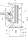
Figure 2 is a longitudinal cross-sectional view of the pit pump. -
Figure 3 is a perspective view of the drive motor portion of the pit pump. -
Figure 4 is a schematic depiction of the drilling system together with a drilling fluid recycling system. - Referring to
Figure 1 , adrilling system 10 is illustrated in which apit pump 12, forming part of a drilling fluid recycling system, described herein can be used. Thedrilling system 10 can be any type of drilling system that drills boreholes in the earth and in which a drilling fluid (or drilling mud) is used to aid in the drilling process. For sake of convenience in facilitating this description, thedrilling system 10 will be described as being a horizontal directional drilling (HDD) system. However, thedrilling system 10 could be a vertical drilling system or other type of drilling system. - The
pit pump 12 is part of a drilling fluid recycling system that is used to recycle used drilling fluid for re-use during a borehole drilling operation. Used drilling fluid from the drilling operation, mixed together with solids from the borehole, can collect in apit 14, which can be an exit pit or an entry pit, with the used drilling fluid mixed with solids then being pumped by thepit pump 12 to a drilling fluid recycler where the used drilling fluid is processed to remove the solids and to make the drilling fluid otherwise suitable for reintroduction back into the borehole. The construction and operation of a drilling fluid recycling system is well known in the art. Thepit 14 is illustrated as having useddrilling fluid 16 therein, and thepit pump 12 is disposed in thepit 14 so that thepit pump 12 is at least partially submerged in the useddrilling fluid 16. Typically, thepit pump 12 will be completely submerged in the useddrilling fluid 16 as is illustrated inFigure 1 . - As will be discussed in further detail below, the
pit pump 12 can be driven by an electric drive motor, and a cooling liquid is used to cool the electric drive motor. The cooling liquid is circulated between thepit pump 12 and anexternal heat exchanger 18 by a cooling liquid supply pipe (or hose) 20 and a cooling liquid return pipe (or hose) 22. One ormore pumps 23 can be provided for circulating the cooling liquid in the closed coolant loop. For example, thepump 23 can be provided in the supply pipe (or hose) 20 within or outside thedrilling fluid 16, in the return pipe (or hose) 22 within or outside thedrilling fluid 16, in theheat exchanger 18 or in thepit pump 12 itself. Theheat exchanger 18 is located outside thepit 14, and is configured to cool the cooling liquid before the cooling liquid is returned back to thepit pump 12 to cool the electric drive motor. Theheat exchanger 18 can be configured as, for example, a liquid-to-air heat exchanger or a liquid-to-liquid heat exchanger. - In addition, electrical energy for powering the electric drive motor of the
pit pump 12 can be provided via apower line 24 from acontroller 26 that is configured to control operation of thepit pump 12 and theheat exchanger 18. In addition, various data signals can be transmitted over adata line 28 between thepit pump 12 and thecontroller 26. Electrical energy for powering operation of the various mechanisms described herein can be supplied from a suitableelectric power supply 30. Data andpower lines 34 can also be provided between thecontroller 26 and theheat exchanger 18 to direct electrical power to theheat exchanger 18, to control operation of theheat exchanger 18, and to send data signals from theheat exchanger 18 to thecontroller 26. - The
electric power supply 30 can be any supply that is suitable for providing electrical power to thepit pump 12. In one embodiment, thepower supply 30 can be an electrical generator. In another embodiment, thepower supply 30 can be line power obtained from an available electrical power line. In addition, two power supply sources can be provided with one power supply acting as a back-up in case of failure of the first or primary power supply. - The
system 10 can further include aHDD rig 32 that is separate from the drilling fluid recycling system. TheHDD rig 32 can have any configuration that is suitable for performing horizontal directional drilling. - One embodiment of the
pit pump 12 is illustrated inFigure 2 . In this embodiment, thepit pump 12 includes apump portion 40 and adrive motor portion 42 that is suitably coupled to thepump portion 40 to drive the pump portion to perform a pumping operation on the useddrilling fluid 16. Theportions portions different portion same portion - The
pump portion 40 can have any configuration that is suitable for pumping the useddrilling fluid 16 mixed with solids. Thepump portion 40 will have an inlet, generically designated as 44, through which the used drilling fluid enters thepump portion 40 and an outlet, generically designated as 46, through which the used drilling fluid exits thepump portion 40. Thepump portion 40 also includes apump impeller 48 or other motive device for pumping the used drilling fluid from theinlet 44 to theoutlet 46. One example of a suitable pump configuration includes, but is not limited to, a centrifugal pump with theinlet 44 being an axial inlet, theoutlet 46 being a radial or tangential outlet, and thepump impeller 48 being rotatably mounted in thepump portion 40. However, other pump configurations can be used. - With continued reference to
Figure 2 along withFigure 3 , thedrive motor portion 42 comprises anoptional housing 80 that defines an interior space in which anelectric drive motor 82 is disposed for driving thepump impeller 48. Theelectric drive motor 82 is powered by electricity provided from theelectric power supply 30 and thecontroller 26. Theelectric drive motor 82 is also reversible in rotation direction in order to be able to reverse the rotation direction of thepump impeller 48. Reversing the direction of rotation of thepump impeller 48 can help to clear away material that may be blocking or impeding flow through thepump inlet 44 or through theimpeller 48. In particular, during pumping theoutlet 46 of thepump portion 40 holds a certain amount of head volume and pressure from the drilling fluid and perhaps other material entrained in the drilling fluid. If thepump impeller 48 is reversed, the head volume and pressure is released back out theinlet 44 of thepump portion 40 thereby dislodging any material that may be lodged in theinlet 44 or in theimpeller 48. - The
electric drive motor 82 can be any drive motor that can be reversed in rotation direction. In one embodiment, theelectric drive motor 82 can include a bi-directional permanent magnet drive motor which permits reversal of the rotation direction. However, other electric drive motors are possible. In addition, as discussed in further detail below, theelectric drive motor 82 is configured to be cooled by a suitable cooling liquid, such as, but not limited to, a 50/50 water/ethylene glycol mix, that is circulated through theelectric drive motor 82. Liquid-cooled electric drive motors are known in the art. - Referring to
Figure 2 , theelectric drive motor 82 includes amotor housing 84 that houses the motor components. Thehousing 84 includes a coolingliquid inlet 86 through which the cooling liquid can be input for cooling the motor components, and a coolingliquid outlet 88 through which the cooling liquid can be output after cooling the motor components. Acoolant hose 90 is within the interior space of thehousing 80 and is connected between theinlet 86 and the supply pipe (or hose) 20 (Figure 1 ) to direct cooling liquid from theheat exchanger 18 after being cooled into themotor housing 84. Similarly, acoolant hose 92 is within the interior space of thehousing 80 and is connected between theoutlet 88 and the return pipe (or hose) 22 (Figure 1 ) to direct cooling liquid back to theheat exchanger 18 to be cooled after absorbing heat in thedrive motor 82. The cooling liquid cools thedrive motor 82 during normal operations of the drive motor as well as during abnormal operations of thedrive motor 82, for example if the pump is stalled. - In one embodiment best seen in
Figure 3 , the supply pipe/hose 20 and the return pipe/hose 22 can be disposed within a common umbilical 94 extending from thehousing 80 which protects the pipes/hoses hose 20 and the return pipe/hose 22 do not need to be disposed in the umbilical 94. Thedata line 28 may also be disposed within the umbilical 94. In addition, electrical energy for powering thedrive motor 82 is routed to thedrive motor portion 42 via a power umbilical 98 extending from thehousing 80 and in which thepower line 24 is disposed to protect thepower line 24 from damage. In another embodiment, all of the data lines and the power lines can be disposed in a single umbilical. - The
drive motor 82 includes a drive shaft 100 (shown in dashed lines inFigure 2 ) that is suitably coupled to thepump impeller 48 using coupling techniques known in the art. - Referring to
Figures 1 and3 , the operation or performance of various components of thepit pump 12 can be electronically monitored and/or operation of thedrive motor 82 can be controlled. Data from various sensors and/or for controlling operation of thedrive motor 82 can be transmitted between thecontroller 26 and thepit pump 12 via the data line(s) 28 within the umbilical 94 (and/or within the umbilical 98). Data can also be transmitted between theheat exchanger 18 and thecontroller 26. - For example, one or more of the following parameters can be monitored by suitable sensors: temperature of the
drive motor 82, temperature of the cooling liquid used to cool thedrive motor 82, torque of thedrive motor 82, revolutions per minute of thedrive motor 82 and/or of the impeller 48 (and/or the shaft 100), horsepower, and vibrations of thedrive motor 82 and/or of thepump impeller 48. Non-pump variables such as the weight of the useddrilling fluid 16, viscosity, head pressure, and the length of the hose connected to theoutlet 46 of thepump portion 40 can also be measured. Moisture in the housing 80 (if present) may also be monitored using one or more sensors. The types of sensors necessary to monitor these parameters are well known in the art. Data from the sensors is routed to the controller 26 (and/or routed to an internal controller of the pump described further below) which can monitor the parameters to determine the health of the individual components and how thepit pump 12 is operating. This permits the performance parameters of various elements of thepit pump 12 to be monitored, and if the monitoring determines that an element is not operating correctly, maintenance can be scheduled to replace or repair the element and/or the sensors. Additional sensors can also be added as needed in order to monitor other parameters. - With reference to
Figure 2 , in another embodiment, acontroller 96 can be incorporated onto thepump 12, for example located on or within thehousing 80 or located on thedrive motor 82 itself. Signals from the various sensors monitoring thepump 12 can be routed to thecontroller 96 which in turn can direct signals outside thepump 12 as well as receive signals, such as control signals for controlling operation of thepump 12, from outside thepump 12. - In still another embodiment, a
power converter 99, such as a DC to AC inverter that converts DC power to AC power or an AC to DC inverter that converts AC power to DC power, can be incorporated onto thepump 12. For example, thepower converter 99 can be located on or within thehousing 80 or located on thedrive motor 82 itself. If present, thepower converter 99 can be connected to thepower line 24 to convert incoming electrical power into the appropriate form for use by thepump 12. -
Figure 4 illustrates an example of the drilling system that includes a drillingfluid recycling system 50 with thepit pump 12 in use withHDD rig 32. The drillingfluid recycling system 50 is a separate system from theHDD rig 32 or other drilling system, and is used to recycle the drilling fluid that is used during drilling operations of theHDD rig 32, and after cleaning the drilling fluid the cleaned drilling fluid is passed through theHDD rig 32 for reintroduction back into the borehole. The drillingfluid recycling system 50 typically does not control any operations of theHDD rig 32, and theHDD rig 32 typically does not control any operations of therecycling system 50. Therecycling system 50 includes adrilling fluid recycler 51 that receives drilling fluid to be recycled from thepump 12. In an example drilling operation, theHDD rig 32 drills a borehole 52 aided by thedrilling fluid 16 which is pumped down theborehole 52 by therecycling system 50. The useddrilling fluid 16 together with solids resulting from the drilling operation are ultimately returned to thepit 14 where thepit pump 12 is disposed. Thepit pump 12 pumps the used drilling fluid mixed with solids to thedrilling fluid recycler 51. In some embodiments, an optional pump 102 (shown in dashed lines) can be disposed between thepump 12 and therecycler 51, for example in-line, to aid in pumping the used drilling fluid to therecycler 51 for recycling. Therecycler 51 removes the solids in a known manner, with the removedsolids 54 being collected. The cleaned drilling fluid is then pumped through theHDD rig 32 on its way back into theborehole 52. While thepit pump 12 is operating, the cooling liquid is circulated from theheat exchanger 18 located outside thepit 14, through the coolingliquid inlet 86, through themotor housing 84 and out through the coolingliquid outlet 86 and back to theheat exchanger 18 to cool the cooling liquid before being returned back to themotor housing 84 to continue the cooling cycle. - In one embodiment, the volume of the used drilling fluid mixed with solids pumped by the
pit pump 12 and the volume of the cleaned drilling fluid pumped back into the borehole 52 can be determined. The difference between these two volumes provides a determination as to the amount of solids being removed from theborehole 52. A significant difference in the volumes of the used and cleaned drilling fluids can provide an indication of possible leakage of the drilling fluid, for example within theborehole 52, in thepit 14, or elsewhere in the path of the drilling fluid. In addition, the amount of solids being removed provides an indication of the drilling operation and whether theborehole 52 is clean enough. - The volume of the used drilling fluid mixed with solids pumped by the
pit pump 12 and the volume of the cleaned drilling fluid pumped into the borehole 52 can be determined using any suitable techniques. For example, mechanical flow meters can be provided at suitable locations at or near the output of thepit pump 12 and at or near the output of the downhole pump. In another embodiment, one or more of the volumes can be determined mathematically using variables and parameters measured from various components of the system. In an embodiment, one or more sensors 85 (seen inFigure 4 ) can be provided at or near the outlet of thepump 12. The sensor(s) 85 is used to detect a volume of the fluid being pumped by thepump 12. The volume of fluid detected by thesensor 85 can then be used to compare against a calculated volume pumped by thepump 12 to validate the calculated volume amount. In addition, the torque on theelectric drive motor 82 can be detected and used to calculate an estimated weight of the drilling fluid in the output of thepump 12. - The examples disclosed in this application are to be considered in all respects as illustrative and not limitative. The scope of the invention is solely defined by the following claims.
Claims (8)
- A pit pump (12) to be used within a pit (14) containing drilling fluid (16) for use with drilling operations performed by a drilling system (10), the pit pump comprising:a pump portion (40) with an inlet (44), an outlet (46), and a pump impeller (48) for pumping drilling fluid (16) from the inlet to the outlet;an electric drive motor (82) in driving engagement with the pump impeller to drive the pump impeller, the electric drive motor includes a motor housing (84);a cooling liquid inlet (86) in the motor housing through which a cooling liquid can be input for cooling the electric drive motor; anda cooling liquid outlet (88) in the motor housing through which cooling liquid can be output after cooling the electric drive motor; characterized in thatthe electric drive motor (82) is reversible whereby a rotation direction of the impeller (48) can be reversed and a flow of fluid through the pump portion (40) can be reversed.
- The pit pump (12) of claim 1, further comprising a controller (96) and/or a power converter (99) on the pit pump.
- The pit pump (12) of claim 2, wherein the electric drive motor (82) is disposed within a housing (80), and the controller and/or power converter are disposed within the housing.
- The pit pump (12) of claim 2, wherein the power converter (99) converts DC power to AC power or converts AC power to DC power.
- The pit pump (12) of claim 1, further comprising a controller (96) on the pit pump, and further comprising at least one sensor electrically connected to the controller.
- The pit pump of claim 5, wherein the controller (96) is configured to calculate a volume of drilling fluid being pumped by the pump portion (40) using data from the at least one sensor (85), and further comprising at least one additional sensor (85) at or near the outlet (46) and electrically connected to the controller (96) for sensing a volume of drilling fluid that is being pumped, and the controller compares the calculated volume with the sensed volume.
- The pit pump of claim 1, further comprising sensors connected to a controller (26, 96) which monitors pump parameters to determine the health of the individual components and how the pit pump (12) is operating.
- A drilling fluid recycling system comprising:the pit pump of claim 1 disposed within a pit (14) containing drilling fluid (16);a heat exchanger (18) located outside the pit, and the cooling liquid inlet (86) and the cooling liquid outlet (88) are fluidly connected to the heat exchanger.
Applications Claiming Priority (2)
| Application Number | Priority Date | Filing Date | Title |
|---|---|---|---|
| US201962819109P | 2019-03-15 | 2019-03-15 | |
| PCT/US2020/022699 WO2020190748A1 (en) | 2019-03-15 | 2020-03-13 | Pit pump for use in a drilling fluid recycling system |
Publications (4)
| Publication Number | Publication Date |
|---|---|
| EP3938658A1 EP3938658A1 (en) | 2022-01-19 |
| EP3938658A4 EP3938658A4 (en) | 2022-05-04 |
| EP3938658C0 EP3938658C0 (en) | 2024-09-18 |
| EP3938658B1 true EP3938658B1 (en) | 2024-09-18 |
Family
ID=72520473
Family Applications (1)
| Application Number | Title | Priority Date | Filing Date |
|---|---|---|---|
| EP20774267.7A Active EP3938658B1 (en) | 2019-03-15 | 2020-03-13 | Pit pump for use in a drilling fluid recycling system |
Country Status (4)
| Country | Link |
|---|---|
| US (1) | US11208859B2 (en) |
| EP (1) | EP3938658B1 (en) |
| CA (1) | CA3133685A1 (en) |
| WO (1) | WO2020190748A1 (en) |
Citations (1)
| Publication number | Priority date | Publication date | Assignee | Title |
|---|---|---|---|---|
| US3961758A (en) * | 1974-08-23 | 1976-06-08 | Peabody Barnes, Inc. | Centrifugal pump with integral grinder |
Family Cites Families (12)
| Publication number | Priority date | Publication date | Assignee | Title |
|---|---|---|---|---|
| US3060335A (en) * | 1961-02-07 | 1962-10-23 | Garrett Corp | Fluid cooled dynamoelectric machine |
| US4331458A (en) * | 1977-12-30 | 1982-05-25 | Smith International, Inc. | Degassing system and centrifugal pump |
| NO175412C (en) * | 1990-11-28 | 1994-10-12 | Norske Stats Oljeselskap | Process for treating waste materials for injection into underground formations |
| US5202194A (en) * | 1991-06-10 | 1993-04-13 | Halliburton Company | Apparatus and method for providing electrical power in a well |
| US5529462A (en) | 1994-03-07 | 1996-06-25 | Hawes; David W. | Universal pump coupling system |
| US5616973A (en) * | 1994-06-29 | 1997-04-01 | Yeomans Chicago Corporation | Pump motor housing with improved cooling means |
| CA2283603A1 (en) | 1998-10-01 | 2000-04-01 | Paul W. Behnke | Forced closed-loop cooling for a submersible pump motor |
| US20020102164A1 (en) | 2001-01-29 | 2002-08-01 | Mark Osadchuk | Pit pump |
| US7731854B1 (en) * | 2007-02-15 | 2010-06-08 | H2O Tech, Inc. | Situ system and method for treating an oil and gas well drilling fluid |
| US20080267785A1 (en) | 2007-04-27 | 2008-10-30 | Gregory Paul Cervenka | Drill rig apparatuses with directly driven shaft & drilling fluid pump systems |
| JP5155113B2 (en) * | 2008-11-19 | 2013-02-27 | 古河産機システムズ株式会社 | underwater pump |
| US20150322775A1 (en) * | 2013-01-28 | 2015-11-12 | Halliburton Energy Services, Inc. | Systems and methods for monitoring wellbore fluids using microanalysis of real-time pumping data |
-
2020
- 2020-03-13 EP EP20774267.7A patent/EP3938658B1/en active Active
- 2020-03-13 CA CA3133685A patent/CA3133685A1/en active Pending
- 2020-03-13 WO PCT/US2020/022699 patent/WO2020190748A1/en not_active Ceased
- 2020-03-13 US US16/818,565 patent/US11208859B2/en active Active
Patent Citations (1)
| Publication number | Priority date | Publication date | Assignee | Title |
|---|---|---|---|---|
| US3961758A (en) * | 1974-08-23 | 1976-06-08 | Peabody Barnes, Inc. | Centrifugal pump with integral grinder |
Also Published As
| Publication number | Publication date |
|---|---|
| WO2020190748A1 (en) | 2020-09-24 |
| EP3938658C0 (en) | 2024-09-18 |
| US11208859B2 (en) | 2021-12-28 |
| US20200318445A1 (en) | 2020-10-08 |
| CA3133685A1 (en) | 2020-09-24 |
| EP3938658A1 (en) | 2022-01-19 |
| EP3938658A4 (en) | 2022-05-04 |
Similar Documents
| Publication | Publication Date | Title |
|---|---|---|
| CN101203678B (en) | Pump, method of operating the pump and pumping station including the pump | |
| US6481973B1 (en) | Method of operating variable-speed submersible pump unit | |
| CA2710728C (en) | Systems and methods for automatic forward phasing determination in a downhole pump system | |
| US7870900B2 (en) | System and method for controlling a progressing cavity well pump | |
| WO2019118352A1 (en) | Air cooled variable-frequency drive | |
| CA2790484A1 (en) | Reverse circulation apparatus and methods for using same | |
| US9133832B2 (en) | Mini-surge cycling method for pumping liquid from a borehole to remove material in contact with the liquid | |
| JP5475607B2 (en) | Pump equipment and operation control device for pump equipment | |
| US9856721B2 (en) | Apparatus and method for injecting a chemical to facilitate operation of a submersible well pump | |
| US11208859B2 (en) | Pit pump for use in a drilling fluid recycling system | |
| KR20200044499A (en) | Geothermal heat pump system with recycling tank and easy sludge removal | |
| CN111492138B (en) | Fluid device | |
| US8246251B1 (en) | Thrust box and skid for a horizontally mounted submersible pump | |
| EP4678871A1 (en) | Real time automated control method for wireline downhole debris collecting while milling operation | |
| AU2020103197A4 (en) | Power and control of a submersible pump | |
| KR20160049846A (en) | Water ring vacuum pump operating system | |
| US20130199775A1 (en) | Monitoring Flow Past Submersible Well Pump Motor with Sail Switch | |
| KR102047446B1 (en) | Underwater motor pump having wireless communication module | |
| JP4637614B2 (en) | Submersible pump oil monitoring device | |
| JP6802083B2 (en) | Vertical pump | |
| JP6614484B2 (en) | Electric submersible pump and electric submersible pump system including the same | |
| JP6709774B2 (en) | Vertical shaft pump and its standby operation method | |
| EP4023888A1 (en) | Pump device | |
| Cashman et al. | Pumps for Groundwater Lowering Duties | |
| JP2005291180A (en) | Pump device |
Legal Events
| Date | Code | Title | Description |
|---|---|---|---|
| STAA | Information on the status of an ep patent application or granted ep patent |
Free format text: STATUS: THE INTERNATIONAL PUBLICATION HAS BEEN MADE |
|
| PUAI | Public reference made under article 153(3) epc to a published international application that has entered the european phase |
Free format text: ORIGINAL CODE: 0009012 |
|
| STAA | Information on the status of an ep patent application or granted ep patent |
Free format text: STATUS: REQUEST FOR EXAMINATION WAS MADE |
|
| 17P | Request for examination filed |
Effective date: 20210920 |
|
| AK | Designated contracting states |
Kind code of ref document: A1 Designated state(s): AL AT BE BG CH CY CZ DE DK EE ES FI FR GB GR HR HU IE IS IT LI LT LU LV MC MK MT NL NO PL PT RO RS SE SI SK SM TR |
|
| A4 | Supplementary search report drawn up and despatched |
Effective date: 20220404 |
|
| RIC1 | Information provided on ipc code assigned before grant |
Ipc: F04D 13/08 20060101ALI20220329BHEP Ipc: E21B 21/01 20060101ALI20220329BHEP Ipc: F04D 15/00 20060101ALI20220329BHEP Ipc: F04D 7/04 20060101ALI20220329BHEP Ipc: F04D 13/06 20060101ALI20220329BHEP Ipc: F04D 29/58 20060101AFI20220329BHEP |
|
| DAV | Request for validation of the european patent (deleted) | ||
| DAX | Request for extension of the european patent (deleted) | ||
| GRAP | Despatch of communication of intention to grant a patent |
Free format text: ORIGINAL CODE: EPIDOSNIGR1 |
|
| STAA | Information on the status of an ep patent application or granted ep patent |
Free format text: STATUS: GRANT OF PATENT IS INTENDED |
|
| INTG | Intention to grant announced |
Effective date: 20240417 |
|
| GRAS | Grant fee paid |
Free format text: ORIGINAL CODE: EPIDOSNIGR3 |
|
| GRAA | (expected) grant |
Free format text: ORIGINAL CODE: 0009210 |
|
| STAA | Information on the status of an ep patent application or granted ep patent |
Free format text: STATUS: THE PATENT HAS BEEN GRANTED |
|
| AK | Designated contracting states |
Kind code of ref document: B1 Designated state(s): AL AT BE BG CH CY CZ DE DK EE ES FI FR GB GR HR HU IE IS IT LI LT LU LV MC MK MT NL NO PL PT RO RS SE SI SK SM TR |
|
| REG | Reference to a national code |
Ref country code: GB Ref legal event code: FG4D |
|
| REG | Reference to a national code |
Ref country code: CH Ref legal event code: EP |
|
| REG | Reference to a national code |
Ref country code: IE Ref legal event code: FG4D |
|
| REG | Reference to a national code |
Ref country code: DE Ref legal event code: R096 Ref document number: 602020037978 Country of ref document: DE |
|
| U01 | Request for unitary effect filed |
Effective date: 20241017 |
|
| U07 | Unitary effect registered |
Designated state(s): AT BE BG DE DK EE FI FR IT LT LU LV MT NL PT RO SE SI Effective date: 20241031 |
|
| PG25 | Lapsed in a contracting state [announced via postgrant information from national office to epo] |
Ref country code: NO Free format text: LAPSE BECAUSE OF FAILURE TO SUBMIT A TRANSLATION OF THE DESCRIPTION OR TO PAY THE FEE WITHIN THE PRESCRIBED TIME-LIMIT Effective date: 20241218 |
|
| PG25 | Lapsed in a contracting state [announced via postgrant information from national office to epo] |
Ref country code: GR Free format text: LAPSE BECAUSE OF FAILURE TO SUBMIT A TRANSLATION OF THE DESCRIPTION OR TO PAY THE FEE WITHIN THE PRESCRIBED TIME-LIMIT Effective date: 20241219 |
|
| PG25 | Lapsed in a contracting state [announced via postgrant information from national office to epo] |
Ref country code: HR Free format text: LAPSE BECAUSE OF FAILURE TO SUBMIT A TRANSLATION OF THE DESCRIPTION OR TO PAY THE FEE WITHIN THE PRESCRIBED TIME-LIMIT Effective date: 20240918 |
|
| PG25 | Lapsed in a contracting state [announced via postgrant information from national office to epo] |
Ref country code: RS Free format text: LAPSE BECAUSE OF FAILURE TO SUBMIT A TRANSLATION OF THE DESCRIPTION OR TO PAY THE FEE WITHIN THE PRESCRIBED TIME-LIMIT Effective date: 20241218 |
|
| PG25 | Lapsed in a contracting state [announced via postgrant information from national office to epo] |
Ref country code: RS Free format text: LAPSE BECAUSE OF FAILURE TO SUBMIT A TRANSLATION OF THE DESCRIPTION OR TO PAY THE FEE WITHIN THE PRESCRIBED TIME-LIMIT Effective date: 20241218 Ref country code: NO Free format text: LAPSE BECAUSE OF FAILURE TO SUBMIT A TRANSLATION OF THE DESCRIPTION OR TO PAY THE FEE WITHIN THE PRESCRIBED TIME-LIMIT Effective date: 20241218 Ref country code: HR Free format text: LAPSE BECAUSE OF FAILURE TO SUBMIT A TRANSLATION OF THE DESCRIPTION OR TO PAY THE FEE WITHIN THE PRESCRIBED TIME-LIMIT Effective date: 20240918 Ref country code: GR Free format text: LAPSE BECAUSE OF FAILURE TO SUBMIT A TRANSLATION OF THE DESCRIPTION OR TO PAY THE FEE WITHIN THE PRESCRIBED TIME-LIMIT Effective date: 20241219 |
|
| PG25 | Lapsed in a contracting state [announced via postgrant information from national office to epo] |
Ref country code: IS Free format text: LAPSE BECAUSE OF FAILURE TO SUBMIT A TRANSLATION OF THE DESCRIPTION OR TO PAY THE FEE WITHIN THE PRESCRIBED TIME-LIMIT Effective date: 20250118 |
|
| PG25 | Lapsed in a contracting state [announced via postgrant information from national office to epo] |
Ref country code: SM Free format text: LAPSE BECAUSE OF FAILURE TO SUBMIT A TRANSLATION OF THE DESCRIPTION OR TO PAY THE FEE WITHIN THE PRESCRIBED TIME-LIMIT Effective date: 20240918 |
|
| PG25 | Lapsed in a contracting state [announced via postgrant information from national office to epo] |
Ref country code: ES Free format text: LAPSE BECAUSE OF FAILURE TO SUBMIT A TRANSLATION OF THE DESCRIPTION OR TO PAY THE FEE WITHIN THE PRESCRIBED TIME-LIMIT Effective date: 20240918 |
|
| PG25 | Lapsed in a contracting state [announced via postgrant information from national office to epo] |
Ref country code: PL Free format text: LAPSE BECAUSE OF FAILURE TO SUBMIT A TRANSLATION OF THE DESCRIPTION OR TO PAY THE FEE WITHIN THE PRESCRIBED TIME-LIMIT Effective date: 20240918 Ref country code: CZ Free format text: LAPSE BECAUSE OF FAILURE TO SUBMIT A TRANSLATION OF THE DESCRIPTION OR TO PAY THE FEE WITHIN THE PRESCRIBED TIME-LIMIT Effective date: 20240918 |
|
| PG25 | Lapsed in a contracting state [announced via postgrant information from national office to epo] |
Ref country code: SK Free format text: LAPSE BECAUSE OF FAILURE TO SUBMIT A TRANSLATION OF THE DESCRIPTION OR TO PAY THE FEE WITHIN THE PRESCRIBED TIME-LIMIT Effective date: 20240918 |
|
| PLBE | No opposition filed within time limit |
Free format text: ORIGINAL CODE: 0009261 |
|
| STAA | Information on the status of an ep patent application or granted ep patent |
Free format text: STATUS: NO OPPOSITION FILED WITHIN TIME LIMIT |
|
| 26N | No opposition filed |
Effective date: 20250619 |
|
| PG25 | Lapsed in a contracting state [announced via postgrant information from national office to epo] |
Ref country code: MC Free format text: LAPSE BECAUSE OF FAILURE TO SUBMIT A TRANSLATION OF THE DESCRIPTION OR TO PAY THE FEE WITHIN THE PRESCRIBED TIME-LIMIT Effective date: 20240918 |
|
| REG | Reference to a national code |
Ref country code: CH Ref legal event code: H13 Free format text: ST27 STATUS EVENT CODE: U-0-0-H10-H13 (AS PROVIDED BY THE NATIONAL OFFICE) Effective date: 20251023 |
|
| U21 | Renewal fee for the european patent with unitary effect paid with additional fee |
Year of fee payment: 6 Effective date: 20250929 |
|
| PG25 | Lapsed in a contracting state [announced via postgrant information from national office to epo] |
Ref country code: CH Free format text: LAPSE BECAUSE OF NON-PAYMENT OF DUE FEES Effective date: 20250331 |
|
| PG25 | Lapsed in a contracting state [announced via postgrant information from national office to epo] |
Ref country code: IE Free format text: LAPSE BECAUSE OF NON-PAYMENT OF DUE FEES Effective date: 20250313 |
|
| U20 | Renewal fee for the european patent with unitary effect paid |
Year of fee payment: 7 Effective date: 20260209 |
|
| PGFP | Annual fee paid to national office [announced via postgrant information from national office to epo] |
Ref country code: GB Payment date: 20260106 Year of fee payment: 7 |