EP3938653B1 - Spacecraft propulsion devices and systems with microwave excitation - Google Patents
Spacecraft propulsion devices and systems with microwave excitation Download PDFInfo
- Publication number
- EP3938653B1 EP3938653B1 EP20735251.9A EP20735251A EP3938653B1 EP 3938653 B1 EP3938653 B1 EP 3938653B1 EP 20735251 A EP20735251 A EP 20735251A EP 3938653 B1 EP3938653 B1 EP 3938653B1
- Authority
- EP
- European Patent Office
- Prior art keywords
- resonant cavity
- nozzle
- propellant
- thruster
- thruster system
- Prior art date
- Legal status (The legal status is an assumption and is not a legal conclusion. Google has not performed a legal analysis and makes no representation as to the accuracy of the status listed.)
- Active
Links
Images








Classifications
-
- H—ELECTRICITY
- H01—ELECTRIC ELEMENTS
- H01J—ELECTRIC DISCHARGE TUBES OR DISCHARGE LAMPS
- H01J37/00—Discharge tubes with provision for introducing objects or material to be exposed to the discharge, e.g. for the purpose of examination or processing thereof
- H01J37/32—Gas-filled discharge tubes
- H01J37/32009—Arrangements for generation of plasma specially adapted for examination or treatment of objects, e.g. plasma sources
- H01J37/32192—Microwave generated discharge
- H01J37/32211—Means for coupling power to the plasma
- H01J37/32247—Resonators
-
- F—MECHANICAL ENGINEERING; LIGHTING; HEATING; WEAPONS; BLASTING
- F03—MACHINES OR ENGINES FOR LIQUIDS; WIND, SPRING, OR WEIGHT MOTORS; PRODUCING MECHANICAL POWER OR A REACTIVE PROPULSIVE THRUST, NOT OTHERWISE PROVIDED FOR
- F03H—PRODUCING A REACTIVE PROPULSIVE THRUST, NOT OTHERWISE PROVIDED FOR
- F03H1/00—Using plasma to produce a reactive propulsive thrust
- F03H1/0093—Electro-thermal plasma thrusters, i.e. thrusters heating the particles in a plasma
-
- B—PERFORMING OPERATIONS; TRANSPORTING
- B64—AIRCRAFT; AVIATION; COSMONAUTICS
- B64G—COSMONAUTICS; VEHICLES OR EQUIPMENT THEREFOR
- B64G1/00—Cosmonautic vehicles
- B64G1/22—Parts of, or equipment specially adapted for fitting in or to, cosmonautic vehicles
- B64G1/40—Arrangements or adaptations of propulsion systems
- B64G1/411—Electric propulsion
- B64G1/417—Electromagnetic fields or flux without mass expulsion
-
- B—PERFORMING OPERATIONS; TRANSPORTING
- B64—AIRCRAFT; AVIATION; COSMONAUTICS
- B64G—COSMONAUTICS; VEHICLES OR EQUIPMENT THEREFOR
- B64G1/00—Cosmonautic vehicles
- B64G1/22—Parts of, or equipment specially adapted for fitting in or to, cosmonautic vehicles
- B64G1/24—Guiding or controlling apparatus, e.g. for attitude control
- B64G1/26—Guiding or controlling apparatus, e.g. for attitude control using jets
-
- B—PERFORMING OPERATIONS; TRANSPORTING
- B64—AIRCRAFT; AVIATION; COSMONAUTICS
- B64G—COSMONAUTICS; VEHICLES OR EQUIPMENT THEREFOR
- B64G1/00—Cosmonautic vehicles
- B64G1/22—Parts of, or equipment specially adapted for fitting in or to, cosmonautic vehicles
- B64G1/24—Guiding or controlling apparatus, e.g. for attitude control
- B64G1/36—Guiding or controlling apparatus, e.g. for attitude control using sensors, e.g. sun-sensors, horizon sensors
-
- B—PERFORMING OPERATIONS; TRANSPORTING
- B64—AIRCRAFT; AVIATION; COSMONAUTICS
- B64G—COSMONAUTICS; VEHICLES OR EQUIPMENT THEREFOR
- B64G1/00—Cosmonautic vehicles
- B64G1/22—Parts of, or equipment specially adapted for fitting in or to, cosmonautic vehicles
- B64G1/24—Guiding or controlling apparatus, e.g. for attitude control
- B64G1/36—Guiding or controlling apparatus, e.g. for attitude control using sensors, e.g. sun-sensors, horizon sensors
- B64G1/366—Guiding or controlling apparatus, e.g. for attitude control using sensors, e.g. sun-sensors, horizon sensors using magnetometers
-
- B—PERFORMING OPERATIONS; TRANSPORTING
- B64—AIRCRAFT; AVIATION; COSMONAUTICS
- B64G—COSMONAUTICS; VEHICLES OR EQUIPMENT THEREFOR
- B64G1/00—Cosmonautic vehicles
- B64G1/22—Parts of, or equipment specially adapted for fitting in or to, cosmonautic vehicles
- B64G1/40—Arrangements or adaptations of propulsion systems
- B64G1/411—Electric propulsion
-
- B—PERFORMING OPERATIONS; TRANSPORTING
- B64—AIRCRAFT; AVIATION; COSMONAUTICS
- B64G—COSMONAUTICS; VEHICLES OR EQUIPMENT THEREFOR
- B64G1/00—Cosmonautic vehicles
- B64G1/22—Parts of, or equipment specially adapted for fitting in or to, cosmonautic vehicles
- B64G1/42—Arrangements or adaptations of power supply systems
- B64G1/428—Power distribution and management
-
- B—PERFORMING OPERATIONS; TRANSPORTING
- B64—AIRCRAFT; AVIATION; COSMONAUTICS
- B64G—COSMONAUTICS; VEHICLES OR EQUIPMENT THEREFOR
- B64G1/00—Cosmonautic vehicles
- B64G1/22—Parts of, or equipment specially adapted for fitting in or to, cosmonautic vehicles
- B64G1/42—Arrangements or adaptations of power supply systems
- B64G1/44—Arrangements or adaptations of power supply systems using radiation, e.g. deployable solar arrays
Definitions
- the disclosure generally relates to operating a spacecraft and more specifically to improving efficiency and reliability of thrusters.
- microwave electrothermal thruster based on a method of electrical propulsion that uses a microwave power source to generate and heat a plasma contained within a resonant chamber or resonant cavity.
- the microwave energy is provided to the chamber by means of a probe (sometimes referred to as an "antenna") or a waveguide. This microwave energy raises the temperature of a gaseous propellant and provides thrust in the form of hot gases exiting the chamber through a nozzle.
- MET thrusters generally are not expected to provide the same amount of thrust as chemical propulsion thrusters which utilize a reduction-oxidation reaction to generate a hot gas that exits via a nozzle and generates thrust.
- D J Sullivan ET AL present the preliminary tests and performance of a prototype microwave electrothermal thruster in the academic paper "Development of a Microwave Resonant Cavity Electrothermal Thruster Prototype".
- the primary component of the device is a microwave resonant cavity and the relevant electromagnetic theory as it relates to the choice of the design of the cavity.
- the device is said to produce stable axial plasmas within a pressurized section of the cavity with the plasma positioned in the inlet region of the nozzle.
- Plasma stability is said to be enhanced by axial power coupling, an optimal distribution of electric power density within the cavity and a propellant gas flow which has a large vortical velocity component.
- SULLIVAN ET AL present a microwave arcjet thruster utilizing microwave energy to create a free-floating plasma discharge within the microwave resonant cavity in the academic paper "Performance Testing and Exhaust Plume Characterization of the Microwave Arcjet Thruster".
- Michael M. Micci presents the performance of a low-power microwave thruster in the academic paper "Low-Power Solid-State Microwave Thruster Systems”. Further, Micci presents that when the low-power microwave thruster is combined with a solid-state microwave source, obviating the need for a power processing unit, the low-power microwave thruster system was found to have significant advantages over other low-power electric propulsion thrusters.
- a spacecraft of this disclosure may be configured for transferring a payload from a lower energy orbit to a higher energy orbit according to a set of mission parameters.
- the mission parameters may include, for example, a time to complete the transfer and an amount of propellant and/or fuel available for the mission.
- the spacecraft may collect solar energy and use the energy to power one or more thrusters. Different thruster types and/or operating modes may trade off the total amount of thrust with the efficiency of thrust with respect to fuel or propellant consumption, defined as a specific impulse.
- propellant In spacecraft propulsion systems, efficient use of propellant may enable better mission parameters (e.g., faster or more payload).
- chemical systems deliver the highest thrust but have the lowest propellant efficiency, as measured by specific impulse.
- electro thermal propulsion electric power is used to directly heat propellant gasses to higher temperatures than can be reached with chemical systems, thereby improving specific impulse.
- the spacecraft in some implementations includes thrusters of different types to improve the efficiency of using solar energy when increasing orbital energy.
- the spacecraft uses the same subsystems for operating the different-type thrusters, thereby reducing the mass and/or complexity of the spacecraft, and thus decreasing mission time while maintaining and/or improving reliability.
- the spacecraft can choose or alternate between thrusters of different types as primary thrusters.
- the spacecraft can optimize these choices for various mission goals (e.g., different payloads, different destination orbits) and/or mission constraints (e.g., propellant availability). Example optimization of these choices can include variations in collecting and storing solar energy as well as in controlling when the different thrusters use the energy and/or propellant, as discussed below.
- Fig. 1 is a block diagram of a spacecraft 100 configured for transferring a payload between orbits.
- the spacecraft 100 includes several subsystems, units, or components disposed in or at a housing 110.
- the subsystems of the spacecraft 100 may include sensors and communications components 120, mechanism control 130, propulsion control 140, a flight computer 150, a docking system 160 (for attaching to a launch vehicle 162, one or more payloads 164, a propellant depot 166, etc.), a power system 170, a thruster system 180 that includes a first thruster 182 and a second thruster 184, and a propellant system 190.
- any combination of subsystems, units, or components of the spacecraft 100 involved in determining, generating, and/or supporting spacecraft propulsion may be collectively referred to as a propulsion system of the spacecraft 100.
- the sensors and communications components 120 may several sensors and/or sensor systems for navigation (e.g., imaging sensors, magnetometers, inertial motion units (IMUs), Global Positioning System (GPS) receivers, etc.), temperature, pressure, strain, radiation, and other environmental sensors, as well as radio and/or optical communication devices to communicate, for example, with a ground station, and/or other spacecraft.
- the sensors and communications components 120 may be communicatively connected with the flight computer 150, for example, to provide the flight computer 150 with signals indicative of information about spacecraft position and/or commands received from a ground station.
- the flight computer 150 may include one or more processors, a memory unit, computer readable media, to process signals received from the sensors and communications components 120 and determine appropriate actions according to instructions loaded into the memory unit (e.g., from the computer readable media).
- the flight computer 150 may be implemented any suitable combination of processing hardware, that may include, for example, applications specific integrated circuits (ASICs) or field programmable gate arrays (FPGAs), and/or software components.
- the flight computer 150 may generate control messages based on the determined actions and communicate the control messages to the mechanism control 130 and/or the propulsion control 140.
- the flight computer 150 may generate a control message to activate one of the thrusters 182, 184 in the thruster system 180 and send the message to the propulsion control 140.
- the flight computer 150 may also generate messages to activate and direct sensors and communications components 120.
- the docking system 160 may include a number of structures and mechanisms to attach the spacecraft 100 to a launch vehicle 162, one or more payloads 164, and/or a propellant refueling depot 166.
- the docking system 160 may be fluidicly connected to the propellant system 190 to enable refilling the propellant from the propellant depot 166. Additionally or alternatively, in some implementations at least a portion of the propellant may be disposed on the launch vehicle 162 and outside of the spacecraft 100 during launch.
- the fluidic connection between the docking system 160 and the propellant system 190 may enable transferring the propellant from the launch vehicle 162 to the spacecraft 100 upon delivering and prior to deploying the spacecraft 100 in orbit.
- the power system 170 may include components (discussed in the context of Figs. 4-7 ) for collecting solar energy, generating electricity and/or heat, storing electricity and/or heat, and delivering electricity and/or heat to the thruster system 180.
- solar panels with photovoltaic cells, solar collectors or concentrators with mirrors and/or lenses, or a suitable combination of devices may collect solar energy.
- the power system 170 may convert the solar energy into electricity and store it in energy storage devices (e.g, lithium ion batteries, fuel cells, etc.) for later delivery to the thruster system 180 and other spacecraft components.
- energy storage devices e.g, lithium ion batteries, fuel cells, etc.
- the power system 180 may deliver at least a portion of the generated electricity directly to the thruster system 180 and/or to other spacecraft components.
- the power system 170 may direct the concentrated (having increased irradiance) solar radiation to photovoltaic solar cells to convert to electricity.
- the power system 170 may direct the concentrated solar energy to a solar thermal receiver or simply, a thermal receiver, that may absorb the solar radiation to generate heat.
- the power system 170 may use the generated heat to power a thruster directly, as discussed in more detail below, to generate electricity using, for example, a turbine or another suitable technique (e.g., a Stirling engine).
- the power system 170 then may use the electricity directly for generating thrust or store electric energy as briefly described above, or in more detail below.
- the thruster system 180 may include a number of thrusters and other components configured to generate propulsion or thrust for the spacecraft 100.
- Thrusters may generally include main thrusters that are configured to substantially change speed of the spacecraft 100, or as attitude control thrusters that are configured to change direction or orientation of the spacecraft 100 without substantial changes in speed.
- the first thruster 182 and the second thruster 184 may both be configured as main thrusters, with additional thrusters configured for attitude control.
- the first thruster 182 may operate according to a first propulsion technique, while the second thruster 184 may operate according to a second propulsion technique.
- the first thruster 182 may be a microwave-electro-thermal (MET) thruster (also may be referred to as a MET rocket).
- MET thruster also may be referred to as a MET rocket.
- a microwave source that may include one or more oscillators included in the thruster system 180 and, upon partial ionization, further heat up, expand, and exit the MET thruster cavity through a nozzle, generating thrust.
- the second thruster 184 may be a solar thermal thruster.
- propellant in a thruster cavity acts as the solar thermal receiver and, upon absorbing concentrated solar energy, heats up, expands, and exits the nozzle generating thrust.
- the propellant may absorb heat before entering the cavity either as a part of the thermal target or in a heat exchange with the thermal target or another suitable thermal mass thermally connected to the thermal target.
- the thruster system 180 may add more heat to the propellant within the cavity using an electrical heater or directing a portion of solar radiation energy to the cavity.
- the propellant system 190 may store the propellant for use in the thruster system 180.
- the propellant may include water, hydrogen peroxide, hydrazine, ammonia or another suitable substance.
- the propellant may be stored on the spacecraft in solid, liquid, and/or gas phase.
- the propellant system 190 may include one or more tanks.
- the propellant system may include one or more pumps, valves, and pipes.
- the propellant may also store heat and/or facilitate generating electricity from heat, and the propellant system 190 may be configured, accordingly, to supply propellant to the power system 170.
- the mechanism control 130 may activate and control mechanisms in the docking system 160 (e.g., for attaching and detaching payload or connecting with an external propellant source), the power system 170 (e.g., for deploying and aligning solar panels or solar concentrators), and/or the propellant system (e.g., for changing configuration of one or more deployable propellant tanks). Furthermore, the mechanism control 130 may coordinate interaction between subsystems, for example, by deploying a tank in the propellant system 190 to receive propellant from an external source connected to the docking system 160.
- the propulsion control 140 may coordinate the interaction between the thruster system 140 and the propellant system 190, for example, by activating and controlling electrical components (e.g., a microwave source) of the thruster system 140 and the flow of propellant supplied to thrusters by the propellant system 190. Additionally or alternatively, the propulsion control 140 may direct the propellant through elements of the power system 170. For example, the propellant system 190 may direct the propellant to absorb the heat (e.g., at a heat exchanger) accumulated within the power system 170. Vaporized propellant may then drive a power plant (e.g., a turbine, a Stirling engine, etc.) of the power system 170 to generate electricity. Additionally or alternatively, the propellant system 190 may direct some of the propellant to charge a fuel cell within the power system 190.
- electrical components e.g., a microwave source
- the propulsion control 140 may direct the propellant through elements of the power system 170.
- the propellant system 190 may direct the propellant to
- a single control unit may control mechanisms and propulsion.
- dedicated controllers may be used for different mechanisms (e.g., a pivot system for a solar concentrator), thrusters (e.g., a MET thruster), valves, etc.
- a controller may refer to any portion or combination of the mechanism control 130 and/or propulsion control 140.
- Fig. 2 illustrates a MET thruster system 280 operating within a spacecraft system 210 that also includes a controller 240, a power system 270, and a propellant system 290.
- the MET thruster system 280 includes a resonant cavity 281 with a thrust axis 277, separated into a propellant compartment 282a and a microwave coupling compartment 282b.
- the resonant cavity 281 also can be referred to as a chamber (e.g., propulsion chamber, resonant chamber, etc.) or a resonator.
- the propellant compartment 282a may be referred to as an upper cavity, and the microwave coupling compartment 282b may be referred to as a lower cavity.
- the resonant cavity 281 extends between a top plate 283a and a bottom plate 283b, and is separated into the two compartments 282a,b by a dielectric window 284.
- a nozzle 285 may be disposed trough the top plate 283a, with the top plate 283a substantially surrounding the nozzle 285.
- a propellant injection structure 286 may be disposed at the top plate 283a (e.g., included into an annular structure that extends into the cavity 281) or at another suitable location in the propellant compartment 282a.
- the propellant injection structure 286 may be fluidicly coupled to the propellant system 290 via a supply line 292.
- the injection structure 286 may include one or more injectors configured to inject propellant into the propellant compartment 282a of the resonant cavity 281 so as to create a rotating circumferential flow.
- the resonant cavity may be made of metal or another suitable material.
- the resonant cavity may be made of a ceramic material with a metal coating in order to improve thermal and conductive properties.
- the microwave coupling compartment 282b of the resonant cavity 281 may electromagnetically couple via a coupling structure 287 to a microwave source 288.
- the coupling structure 287 couples energy into the cavity 281 via an evanescent electromagnetic field.
- the microwave source may include one or more microwave generators or oscillators (e.g., magnetrons, solid-state Colpitts circuits, etc.), amplifiers, phase controllers, switches, and/or other suitable microwave circuits and devices. Combining multiple oscillators in a microwave source 288 is discussed in reference to Figs. 3A and 3B .
- the microwave coupling structure 287 may include a coaxial cable terminated with a probe or an antenna, or a waveguide terminated with one or more apertures to couple electromagnetic energy generated by the microwave source 288 to a mode (or multiple modes) of the resonant cavity 281.
- the coupling structure may include impedance matching or tuning elements (e.g., stubs, quarter-wave transformers, etc.). Example coupling structures are discussed with reference to Figs. 6A,B and 7A,B .
- the microwave source 288 By way of the coupling structure 287, the microwave source 288 generates standing waves with spatial power distribution defined by the excited modes in the resonant cavity 281.
- the power delivered to the mode(s) of the resonant cavity 281 may ionize a portion of the injected propellant, creating plasma that subsequently absorbs more electromagnetic energy.
- the energy absorbed by the plasma heats the surrounding propellant that increases in temperature and pressure and escapes the propellant compartment 282a through the nozzle 285 to generate thrust.
- Substantially confining the plasma to a suitable region near an inlet of the nozzle 285 increases efficiency of the thruster system 280.
- One way of confining the plasma is to introduce rotating circumferential flow of the injected propellant, as briefly discussed above and, in more details with reference to Figs. 8A, 8B .
- Alternative implementations of the thruster system 210 may not include a resonant cavity 281 (e.g., as discussed with reference to Fig. 4 ) or may integrate the resonant cavity into the coupling structure 287 (e.g., as discussed with reference to Fig. 5 ).
- the thruster system 280 may be implemented at least in part on a circuit board, with integrated and discrete components.
- Solid-state oscillators may be used to implement the microwave source 288.
- Micro-strip and coplanar or other suitable transmission lines can implement the coupling 287, and at least a portion of the propellant cavity 281 may be etched through the circuit board.
- additional components may surround the portion of the nozzle 285 outside the resonant cavity 281.
- the components may be configured for further heating the gas exiting the nozzle 285 and/or for directing the flow of the exiting gas by static or electric or magnetic field. In this manner, the thruster can improve specific thrust I SP
- the MET thruster system 280 can be configured to operate in a MET mode as well as a chemical propulsion mode.
- the MET thruster system 280 can generate thrust by forming a hot gas in the cavity 281 using a reduction-oxidation reaction between a first fluid (e.g., hydrozene) and a second fluid (e.g., hydrogen peroxide).
- the first and second fluids can operate as reducing and oxidizing agents, respectively.
- the same fluid e.g., hydrozene
- the MET thruster system 280 in some implementations can employ fuel cells that store oxygen and hydrogen separately, and thus the same fluid, water, can be used as a propellant ion the MET mode of operation and as a source of the reducing and oxidizing agents in the chemical mode of operation.
- Fig. 3A illustrates an architecture for directing signals from multiple microwave oscillators or generators to one or more MET thrusters.
- the example architecture includes four generators 31 0a-d, each generating a respective signal.
- the signals may be substantially continuous wave (CW) signals in the range of 1-20 GHz.
- the signals may have substantially different frequencies (e.g., with frequency differences no less than 1 kHz, 10 kHz, 100 kHz or another suitable minimum difference).
- the signals may have substantially similar frequencies (e.g., with frequency differences less than 1 kHz, 100 Hz, 10 Hz or another suitable minimum difference).
- the architecture 300 may include phase adjustment components 320a-d configured to adjust the phase of each of the corresponding signals corresponding to each of the generators 310a-d. The architecture 300 may then direct the phase-shifted signals to a switching network 330.
- the switching network 340 may include a suitable number of routing devices, including splitters, combiners, electro-mechanical switches, micro-electro-mechanical system (MEMS) switches, solid state switches, etc.
- the switching network 340 may provide an output to one of two MET thrusters 350a,b. In some implementations, only one MET thruster may be used, while more than two MET thrusters may be used in other implementations.
- the generators 31 0a-d may be configured to phase-lock to generate signals of substantially the same frequency and with substantially consistent pair-wise phase differences between phase difference between phase-locked generators.
- the phase adjustment components 320a-d may be filters.
- the phase adjustment components 320a-d may be delay lines. In either case, the phase-adjustment components 320a-d may be tunable.
- a controller adjusts the phases of the components 320a-d to facilitate phase-locking or to increase the power output of the combined signals.
- the switching network 340 may direct output to a single MET thruster (i.e., coupling energy into the resonant cavity of the MET thruster). In other implementations, the switching network may direct one portion of the output to one thruster and another portion of the output to another thruster. In a redundant MET thruster system that includes multiple microwave generators 310a-d and multiple MET thrusters 350a,b, the switching network 340 may direct a subset of the signals generated by the generators 310a-d, to one or both of the MET thrusters 350a,b.
- Fig. 3B illustrates an example three-dimensional placement of microwave oscillators or generators 360a-d relative to a load 370, which can be the resonant cavity, for example (such as the resonant cavity 281 discussed with reference to Fig. 2 ).
- the generators 360a-d are interconnected via respective transmission or wave guides 380a-d. The lengths of the guides 380a-d can be adjusted so that the generators 360a-d are phase-locked and configured to increase the power delivered to the load 370.
- Fig. 4 illustrates a MET thruster configuration 400 that does not require a resonant cavity. Instead, the microwave source 410 delivers energy via a waveguide 420 to a propellant compartment 430 disposed through the waveguide 420.
- the propellant compartment 430 includes a nozzle 432.
- the microwave energy delivered to the propellant compartment 430 ignites a plasma and heats the gaseous propellant that generates thrust by expanding through the nozzle 432.
- a power system 470 e.g., the power system 270 of Fig. 2
- a propellant system 490 e.g., the propellant system 290
- the MET thruster configuration 400 may operate within the spacecraft system 210.
- Fig. 5 illustrates another MET thruster configuration 500.
- the microwave source 510 delivers energy via a coaxial transmission line 520 to a propellant compartment 530 disposed between a center conductor and a shield (an outer conductor) of a section of the coaxial transmission line 520.
- the microwave energy delivered to the propellant compartment 530 ignites a plasma and heats the gaseous propellant that generates thrust by expanding through the nozzle 532.
- a power system 570 e.g., the power system 270 of Fig. 2
- a propellant system 590 e.g., the propellant system 290
- a section of the coaxial transmission line proximal to the nozzle 532 and including the propellant compartment 530 may form a resonance cavity.
- a section of the coaxial transmission line 520 may include an impedance transformation section with coaxial stubs, quarter-wave impedance transformer, or another suitable impedance matching circuit.
- the center conduct of the coaxial transmission line 520 within the propellant compartment 530 may be coated with a dielectric material to protect it from degradation caused by plasma.
- the coaxial transmission line 520 can include a dielectric window to define the propellant compartment 530 (i.e., separate a one portion of the coaxial transmission line from another portion of the coaxial transmission line in which the hot gas is contained).
- a MET thruster of this disclosure in some implementations includes a resonant cavity 601 (which can be similar to the resonant cavity 281 discussed above and include a dielectric window 605 separating the cavity into two compartments), the resonant frequency of which a controller (e.g., the controller 240 of Fig. 2 ) can tune.
- a controller e.g., the controller 240 of Fig. 2
- one or more magnets 602 exert a magnetic bias onto a ferrite insert 604 disposed inside the resonant cavity 601.
- the one or more magnets 602 are electromagnets which the controller can activate and deactivate as needed.
- the controller 240 can activate the electromagnet(s) 602 when at least a portion of the propellant inside the resonant cavity 601 is ionized.
- the propellant entering the resonant cavity 601 at an initial stage of operating the MET thruster can heat up and remain unionized until a certain time (and, at a time T 3 in Fig. 15 ), when the propellant begins to form plasma and accordingly begin to impact the resonant frequencies of the resonant cavity 601.
- the controller 240 can determine this time using temperature sensors disposed in or near the resonant cavity 601 or, in another implementation, by determining the amount of time elapsed since the propellant began entering the resonant cavity at a certain flowrate and using a look-up table to determine when the controller 240 should activate the electromagnets 602.
- the one or more magnets 602 are disposed along the vertical wall of the cylindrical housing of the resonant cavity 601 (with the position of a nozzle 610 defining the vertical orientation of the resonant cavity 601).
- the corresponding ferrite insert(s) 604 are disposed inside the resonant cavity 601, along the vertical wall of the cylindrical housing, so that the vertical wall of the resonant cavity 601 separates each of the one or more magnets 602 from the corresponding ferrite insert 604.
- a waveguide 620 couples microwave energy to the resonant cavity 601 at the base of the cylindrical housing of the resonant cavity 601.
- the one or more magnets 652 are disposed outside the base of the cylindrical housing of the resonant cavity 651 (which also can be similar to the resonant cavity 281 discussed above and can include a dielectric window 655), at an end opposite to the end at which the nozzle 660 is disposed.
- the ferrite insert 654 is disposed inside the resonant cavity 651 at the base of the cylindrical housing, so that the plate at the base of the resonant cavity 651 separates each of the one or more magnets 652 from the corresponding ferrite insert 654.
- a waveguide 670 couples microwave energy to the resonant cavity 651 at a vertical wall of the cylindrical housing of the resonant cavity 651.
- a MET thruster implements a combination of the techniques of Figs. 6A and 6B . More generally, a MET thruster can include one or more ferrite inserts at any suitable locations within the resonant cavity and one or more magnets disposed at the suitable corresponding locations outside the resonant cavity. Moreover, in the some implementations the magnets can be permanent (e.g., rare earth magnets) mechanically actuated to interact with the ferrite inserts.
- a resonant cavity 701 includes a dielectric window 705 and is disposed within a cylindrical housing, similar to the resonant cavity 281 discussed above.
- a waveguide 720 abuts the base of the cylindrical housing, at an end opposite to the end where a nozzle 710 is disposed.
- the waveguide 720 can have a rectangular cross-section for example.
- the waveguide 720 couples electromagnetic energy from a microwave source, such as the microwave source 288 of Fig. 2 , into the resonant cavity 701 via an aperture 730.
- the aperture 730 has a round shape.
- a resonant cavity 751 also includes a dielectric window 755 and is disposed within a cylindrical housing, similar to the resonant cavity 281 discussed above.
- a waveguide 770 wraps around at least a portion of the circumference of the cylindrical housing. The waveguide 770 thus abuts the vertical wall of the cylindrical housing.
- the waveguide 770 includes an aperture in the shape of a narrow slit, with the longer dimension of the slit parallel to the axis of the resonant cavity 751 (i.e., the axis of the cylindrical housing).
- the waveguide 770 includes multiple apertures in the section that abuts the cylindrical housing of the resonant cavity 751, so as to increase coupling efficiency.
- the waveguide 770 can include two, three, four, etc. apertures shaped similar to the aperture 780, via each of which the microwave source can deliver microwave energy into the resonant cavity 751.
- a waveguide similar to the waveguide 720 or 770 can define a tangent to the circumference of the resonant cavity, and couple electromagnetic energy from a microwave source into the resonant cavity via a single aperture.
- an example resonant cavity 801 includes an annular structure 810 that extends into the resonant cavity 801 along the thrust axis 803 to support or include one or more injectors 820.
- two injectors 820A and 820B are separated from each other by 180 degrees along a circumference concentric with the circumference of the annular structure.
- the annular structure 810 supports four injectors, separated by each other by 60 degrees. More generally, the annular structure 810 can support N injectors, which can be separated from each other by 360/N degrees (or another suitable angular distance).
- the annular structure 810 in this implementation does not extend above a top plate 830 which supports a nozzle 832.
- the annular structure 810 in other implementations can extend above the top plate 830.
- the annular structure 810 can form an exit cone of the nozzle 832.
- the nozzle 832 has an integral structure, including an exit cone, and is provided separately of the annular structure 810.
- the annular structure 810 can include channels extending from the respective inlets 822A and 822B into the cavity 801 to define injectors 820A and 820B, or the channel can receive hollow tubes of the injectors 820A and 820B.
- the injectors 820A and 820B are configured to create or improve a rotating circumferential flow of the hot gas in the cavity 801.
- the annular structure 810 can define a suitable geometry for the injectors 820A and 820B, e.g., curve the channels of the injectors 820A and 820B so that the propellant enters the cavity 801 at an angle relative to the thrust axis 803, or provide substantially straight channels at an angle to the thrust axis 803.
- the injectors 820A and 820B impart angular momentum to the propellant entering the cavity 801, which in turns facilitates the creation of a rotating circumferential flow 840 of hot gas in the cavity 801.
- the annular structure 810 can orient the outlets 824A and 824B so that the injectors 824A and 824B impart angular momentum to the propellant along the same direction, e.g., clockwise as illustrated in Fig. 8A or counterclockwise.
- the annular structure 810 defines the location of outlets 824A and 824B of the injectors 820A and 820B, respectively.
- the annular structure 810 determines the respective locations of the outlets 824A and 824B in terms of a distance along the thrust axis 803 as well as in terms of a radial distance along a perpendicular to the thrust axis 803.
- the annular structure 810 thus can facilitate injection of the propellant close to the location within the cavity 801 where plasma is formed (rather than near the top plate 830 for example).
- the annular structure 810 in an example implementation includes a section 850 with a radius that increases with the distance away from the nozzle 832.
- the section 850 thus is shaped as a conical frustum to further improve vorticity and facilitate the creation of a rotating circumferential flow of hot gas.
- Fig. 8B illustrates an example resonant cavity 861 in which the injectors 870A and 807B are implemented as capillaries.
- the capillaries are not supported by an annular structure, and the point at which propellant enters the resonant cavity 861 is defined by the shape and the material of the capillaries.
- the injectors 870A and 807B can impart angular momentum to the propellant entering the cavity 861, which in turns facilitates the creation of a rotating circumferential flow of hot gas in the cavity 861.
- Fig. 8C illustrates an example resonant cavity 881 in which injectors 890A are 890B are implemented as capillaries disposed outside an annular structure 880 which, similar to the annular structure 810 of Fig. 8A , extends into the resonant cavity 881.
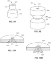
- Figs. 9A and 9B illustrate several example geometries of a resonant cavity, which can be used as the resonant cavity 281 in the MET thruster of Fig. 2 , for example.
- the resonant cavity 901 includes a bottom section 910, a middle section 912, and a top section 914 most proximate to a nozzle 920.
- the bottom section 910 and the top section 914 have a constant diameter, but the bottom section 910 has a wider diameter than the top section 914.
- the middle section 912 has a diameter that decreases along the cylinder axis, so that the portion of the middle section 912 closer to the nozzle 920 is narrower than the portion of the middle section 912 farther away from the nozzle 920.
- diameter decreases linearly, and the middle section 912 forms a conical frustum which can improve vorticity and facilitate the creation of a rotating circumferential flow of hot gas.
- the diameter need not vary linearly and can vary in any suitable manner (e.g., exponentially).
- the resonant cavity 951 includes a bottom section 960, a first conical frustum section 962, a middle section 964, a second conical frustum section 964, and a top section 968 most proximate to a nozzle 970.
- the bottom section 960 and the top section 968 have the same constant diameter.
- the middle section 964 has a constant diameter smaller than the diameter of the bottom section 960 and the top section 968.
- the diameter of the first conical frustum section 962 decreases along the cylinder axis, so that the portion closer to the nozzle 970 is narrower than the portion farther away from the nozzle 970.
- the diameter of the second conical frustum section 966 increases along the cylinder axis, so that the portion closer to the nozzle 970 is wider than the portion farther away from the nozzle 970.
- the diameter can vary non-linearly in other implementations of the section 962 and/or the section 966.
- the geometry of the resonant cavity 951 also can improve vorticity and facilitate the creation of a rotating circumferential flow of hot gas.
- an example monolithic nozzle 1000 can be disposed in a top plate 1002 of a resonant cavity, such as the resonant cavity of 281 illustrated in Fig. 2 .
- the entire nozzle 1000 can be made of the same material such as a ceramic, for example, or metal with ceramic coating.
- the nozzle 1000 can include a flange 1010 via which the nozzle 1000 attaches to the top plate 1002. The flange 1010 prevents the nozzle 1000 from being expelled due to pressure inside the resonant cavity.
- an example monolithic nozzle 1050 similarly can be disposed in a top plate 1052 of a resonant cavity.
- the entire nozzle 1050 can be made of the same material.
- a portion 1060 of the nozzle 1060 extends into the resonant cavity to increase the intensity of the electric field that acts upon the propellant. The portion that extends into the cavity can prevents the nozzle 1060 from being expelled due to pressure inside the resonant cavity, similar to the flange 1010 of the nozzle 1000 discussed above.
- Fig. 11 illustrates an example configuration 1100 in which concentric annular inserts 112 and 114 in a top plate 1102 surround a nozzle 1110.
- Fig. 11 illustrates two concentric annular inserts, in other implementations a single concentric annular insert is used or, conversely, more than two such inserts are used.
- the top plate 1102 can be disposed at an end of a resonant cavity (e.g., the resonant cavity 281 discussed above).
- the top plate 1102 can be made of a certain material, such as steel or another suitable metal alloy or metal, with a first coefficient of thermal expansion (CTE) ⁇ 1 .
- the CTE of the material of the nozzle can be ⁇ 2 different from ⁇ 1 .
- the nozzle 1110 can be made of a ceramic material with a lower CTE than metal, or the nozzle 1110 can have a ceramic coating.
- the top plate 1102 may exert pressure on the nozzle 1110, which over time may lead to deterioration of the nozzle 1110. For example, the throat of the nozzle 1110 may get narrower or uneven.
- the concentric annular insert 1112 is disposed between the nozzle 1110 and the top plate 1102 (directly adjacent to the top plate 1102 or adjacent via another one or more annular concentric inserts).
- the concentric annular insert 1112 has a coefficient of thermal expansion ⁇ 3 different from ⁇ 2 and ⁇ 1 .
- ⁇ 3 is smaller than ⁇ 2 and ⁇ 1 .
- the concentric annular insert 1112 reduces the thermal stress which the top plate 1102 exerts on the nozzle 1110 and, in particular, on the throat of the nozzle.
- the CTE ⁇ 3 is smaller than ⁇ 1 but equal to or greater than ⁇ 3 .
- the concentric annular insert 1112 is made of an elastic material to absorb the stress exerted by the top plate 1102.
- the thermal coefficients of the concentric annular inserts can be selected so as to provide values between layers, e.g., the CTE ⁇ 4 of the concentric annular insert 1114 can be between the CTEs ⁇ 3 and ⁇ 1 of the concentric annular insert 1112 and the top plate 1102, respectively.
- a configuration 1200 illustrates an adapter 1200 configured to removably attach to a top plate 1204 (illustrated in Fig. 12B ), which can be disposed at an end of a resonant cavity.
- the adapter 1200 can include a flange 1202 that exerts a force on the top plate 1204 to prevent the adapter 1200 from being expelled by pressure within the resonant cavity.
- the adapter 1202 supports a nozzle 1210. In some situations, it may be easier to form an adapter similar to the adapter 1200 for a desired nozzle than adapt a nozzle directly to the top plate 1204.
- Fig. 13 illustrates an example nozzle insert 1300 which can be used to protect the throat of a nozzle 1302.
- the nozzle insert 1300 can be made of a refractory metal or another suitable material that can reduce the oxidation of the nozzle 1302.
- the nozzle insert 1300 is made of iridium.
- the nozzle insert 1300 is made of niobium.
- Fig. 13 illustrates a single-layer nozzle insert 1300, in general a suitable nozzle insert can be have any suitable number of layers (e.g., two, three, four).
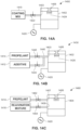
- Fig. 14A is a block diagram of an example configuration 1400 in which a coating mix 1410 for depositing a coating material onto the inner surface of a nozzle 1406 can be injected into a resonant cavity 1402 during manufacturing.
- a controller (which need not be associated with a spacecraft) can provide a control signal 1420 to a valve 1422 disposed in a fluid line between a pressurized tank with the coating mix 1410 and the resonant cavity 1402.
- the controller can cause the coating mix 1410 to be injected into the resonant cavity 1402 via an inlet 1403 when a microwave source 1420 (which can be similar to the microwave source 288 for example) can couple electromagnetic energy generated into the resonant cavity 1402.
- the energy produces hot gas 1422 from the coating mix 14010 in the resonant cavity 1402, and the pressure in the resonant cavity 1402 expels the hot gas 1424 via the nozzle 1406.
- the hot gas coats the throat (the interior surface) of the nozzle 1406 with a coating material.
- the coating material in various implementations can be (or can include) oxide ceramics, non-oxide ceramics, or a refractory metal such as tungsten. Further, in some implementations the hot gas coats the throat of the nozzle with a diamond film or a sapphire film. To this end, the coating mix 210 includes a coating agent, so that the coating or film deposited onto the throat of the nozzle 1406 is a chemical product of the coating agent.
- the nozzle 1406 alone, or along with the resonant cavity 1402 can be deployed in a spacecraft.
- the resonant cavity 1402 receives a propellant via the same inlet 1403.
- a thruster installation including the resonant cavity 1402 and the nozzle 1406 can operate in a first mode in which the microwave energy produces hot gas to coat the nozzle 1406, and a second mode in which the microwave energy produces hot gas from the propellant to generate thrust, when the spacecraft is deployed in space.
- Fig. 14B is a block diagram of an example configuration 1430 in which an additive 1412 for depositing a coating material onto the inner surface of the nozzle 1406 can be injected into the resonant cavity 1402 in a certain operational mode of the thruster.
- the same or similar resonant cavity 1402 with the inlet 1403 can be coupled to a fluid line 1440 via which the controller of the spacecraft (e.g., the controller 240 of Fig. 2 ) can selectively cause only the propellant 1414 to be injected into the resonant cavity 1402, or a mixture of the propellant 1414 and an additive 1412.
- the controller can operate valves 1442 and 1444.
- the additive 1412 in various implementations can be (or can include) oxide ceramics, non-oxide ceramics, a refractory metal such as tungsten, a coating agent that forms a diamond film or a sapphire film, etc.
- the microwave energy from the microwave source 1420 produces hot gas 1426 from the propellant 1414 and the additive 1412, and the pressure in the resonant cavity 1402 expels the hot gas 1426 via the nozzle 1406, thereby coating the throat of the nozzle 1406 with a coating material included in the additive 1412.
- the hot gas is generated from the propellant 1414 alone.
- Fig. 14C is a block diagram of yet another example configuration 1460 in which a coating mix for depositing a coating material onto the inner surface of a nozzle can be injected into a resonant cavity along with the propellant.
- a resonant cavity 1404 in this implementation includes two inlets 1407 and 1409 to receive a propellant 1414 or a "rejuvenation mixture" 1416, respectively.
- the rejuvenation mixture 1416 can be similar to the additive 1412, or include additional chemical agents suitable for protecting the nozzle 1406 from oxidation, erosion, etc.
- the controller can operate valves 1462 and 1462 to supply the propellant 1414, the rejuvenation mixture 1416, or both into the resonant cavity 1404.
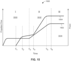
- a diagram 1500 Fig. 15 depicts a curve 1504 representing power output of a microwave generator as well as a curve 1502 representing rate at which a propellant is injected into a resonant cavity, plotted on a shared timeline, according to which a MET thruster of this disclosure (e.g., the MET thruster system 280) can operate.
- the diagram 1500 illustrates an ignition stage 1510, during which the thruster operates in an ignition mode, an intermediate stage 1512, during which the thruster ramps up the power and propellant flow, and a propulsion stage 1514, during which the thruster operates in a propulsion mode.
- a controller of the thruster causes the propellant to start flowing into the resonant cavity at a first, relatively low and relatively constant, rate.
- the controller operates the microwave source in the low-rate mode until time T 3 , at which the thruster transitions from stage 1510 to stage 1512.
- the controller activates the power source and begins to supply the electromagnetic power to the resonant cavity.
- the controller ramps up the power until time T 2 (subsequent to time T 1 and prior to time T 3 ).
- the controller determines (based on sensor inputs or using a look-up table, for example) that the propellant is approaching the state at which at least a portion of the propellant is ionized.
- the controller in this implementation starts increasing the power output more gradually until time T 4 .
- the controller determines that at least a portion of the propellant is ionized in the resonant cavity and begins to ramp up the flow rate.
- the controller can also ramp up the power, starting a later time T 4 .
- the controller can stop ramping up the power and the flow rate at times T 5 and T 6 , respectively.
- the controller then cause the thruster to operate in the propulsion mode, in which both the power and the flow rate are at a relatively high and relatively constant level.
- the controller further can vary the flow rate of the propellant at the propulsion stage 1514 in accordance with the desired thrust, i.e., the graph 1502 can "plateau" at different levels.
- MET microwave electro thermal
- propellant gas is heated to high temperature in a small volume by an electric discharge from an intensely focused microwave field.
- the high temperature gas is focused into the throat of a thruster nozzle where the hot gas is extracted and accelerated to high velocity thereby producing efficient thrust.
- the hot gas is focused by action of swirling the gaseous propellant in the region outside of the electric discharge. It is a general principle that centrifugal forces acting on a rotating column of gas will concentrate hotter and less dense gases along the axis of rotation while cooler and more dense gases will be pulled away from the axis of rotation.
- the present system and method describes the placement of gas flow injectors surrounding the thruster nozzle and discharge region.
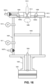
- Fig. 16 illustrates certain details of an example thruster (e.g., thruster 280) in the context of propellant injection.
- a powerful source of microwave energy 1601 e.g., the microwave source 288, such as a magnetron, delivers microwave power through a coaxial transition structure 1602 (or any suitable coupling structure, e.g., structure 288) to a hollow microwave resonator 1603 (such as resonant cavity 281).
- An antenna 1604 at the end of the coaxial structure 1602 causes microwave energy to radiate into the resonator 1603.
- the resonator 1603 is resonant at the frequency of the incoming microwave energy which causes an intense standing wave microwave field to fill the resonator.
- a pressure-tight dielectric window 1605 (e.g., window 284) divides the resonator 1603 into two compartments which may be independently pressurized.
- the dielectric window 1605 is substantially transparent to the microwave fields and does not substantially disturb the standing wave pattern within the resonator 1603.
- Multiple gas feed connections 1607a and 1607b may allow the two compartment halves to be separately pressurized with appropriate gasses. Pressures in the two compartment halves may be independently monitored by pressure sensors 1610 and 1611.
- a localized electric discharge 1606 develops in a propellant gas injected through the feed 1607a.
- the propellant gas is caused to rotate (in a circumferential flow), as discussed above.
- the microwave radiation may heat a small volume of the gas to high temperature.
- Gas pressure from continuously injected gas forces the heated rotating gas flow into the throat of thruster nozzle 1613.
- the gas then exits through the thruster nozzle 1613 where it is accelerated to become a high speed stream 1612 producing rocket thrust.
- Thruster nozzle 1613 may be further provided with means, e.g., a threaded connection, to permit it to be adjusted more or less protruding into the resonator 1603.
- the top end plate of the resonator 1603 includes two parts (1614 and 1615) in order to permit gas flow channels to be machined within the interior of the assembled top plate.
- the lower half 1614 of the top end plate includes gas injectors 1609a,b and a lower half of a circumferential gas distribution channel 1608.
- the top half 1615 of the end plate may include the gas feed connection 1607a fluidicly coupled to the upper half of the circumferential gas distribution channel 1608.
- Gas injectors 1609a,b may direct the propellant gas, such as water vapor, tangentially (i.e., substantially perpendicular to the radial direction of the resonator 1603) into the resonator 1603 to produce the rotating gas flow.
- the gas injectors 1609a,b may be placed at a substantially optimal radial distance from the nozzle 1613 to best focus the electrical discharge 1606 toward the throat of nozzle 1613.
- the optimal radial position may depend on operational details of the rocket such as operating pressure, mass flow rate, and type of gas in use.
- the standing wave fields inside resonator 1603 are indicated schematically.
- Electric fields 1716 are represented by curved solid arrows.
- Magnetic fields 1717 are represented by curved broken (dashed) arrows.
- the resonator 1603 may be constructed in a size to support a TM011 standing wave mode.
- the resonator 1603 may be constructed in a size to match the wavelength of the microwave source 1601. This standing wave mode is chosen because it concentrates electric fields 1716 at the center of each end of the resonator.
- Highly intense concentrated electric fields 1716 provide the mechanism for producing the localized electric discharge 1606 in the propellant gas.
- the swirl injectors 1609a-d are located close to the thruster nozzle 1613.
- the injectors 1609a-d fluidicly connect to the gas distribution channel 1608 through angled connector channels 1919.
- the connector channels 1919 and the multiple gas injectors 1609a-d may be angled in a circumferential direction to induce a circumferentially rotating gas flow.
- the injectors 1609a-d and the associated connector channels 1919 may be angled along the axial direction into the plane of the lower half 1614 until they emerge at the lower surface of the top end plate. In this manner, rotating gas may be injected close to the end plate of the resonator 1603 and also close to the electrical discharge 1606.
- the nozzle 1613 may be made from a refractory material such as ceramic or tungsten metal.
- the view of the nozzle 1613 in Figs. 18 and 19 is looking along the axis of the nozzle 1613 from inside the resonator 1603.
- the propulsion gas enters the upper half 1615 of the top end plate through the gas feed connection 1607a. Gas flows through a gas flow channel 1808 and the upper half of the circumferential gas distribution channel 1608.
- the upper half 1615 of the top end plate may direct gas to any number of gas injectors located in the lower half 1614.
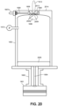
- Fig. 20 illustrates another embodiment of a MET thruster.
- a pressure-tight dielectric window 2005 is disposed at the bottom of the resonator 1603, leaving a single pressurized compartment within the resonator 1603.
- the top end plate is fabricated from a single plate 2014.
- the gas injectors 2009 are disposed directly in the nozzle 2013 in close proximity to a throat 2020.
- Fig. 21 is an end view of the embodiment illustrated in Fig. 20 .
- Fig. 21 illustrates details of the placement of gas injectors 2009a-d disposed in the nozzle 2013 as they surround the nozzle throat 2020.
- Thrusters or rockets may be constructed with two important example features: i) a pressure resistant chamber contains a hot propellant gas at high pressure, ii) the hot pressurized propellant gas then passes from the chamber into the throat of a nozzle.
- a converging-diverging configuration of the nozzle may extract flowing gas from the chamber and accelerate the gas to a substantially high velocity, thereby producing efficient thrust.
- the pressure resistant chamber When hot gas is produced by combustion of fuel and oxidizer, the pressure resistant chamber is usually termed a combustion chamber, and the propellant gas consists of a mixture of gaseous combustion products.
- propellant gas When propellant gas is heated by non-combustion means (e.g., as in the MET thrusters or thruster modes discussed above) such as electrical heating, optical heating, or other directed energy heating means, then the pressure resistant chamber may be termed a propulsion chamber.
- the usefulness of a rocket system is increased by efficient conversion of the input thermal energy, whether from chemical or electrical means, into produced thrust. It may be advantageous to minimize thermal energy losses by reducing thermal heat flow out of the propellant gas and through the walls of the propulsion chamber and the walls or the expansion nozzle. Notably, potential heat loss problems may be exacerbated when rocket thrusters are reduced in size. Smaller thrust chambers have more surface area per total volume than larger chambers which leads directly to reduction in thermal efficiency, other factors being equal.
- Possible heat loss mitigation methods provide for the use of heat-resistant or refractory materials in the walls of the propulsion chamber and nozzle.
- Refractory materials allow the surfaces to operate at high temperatures, thus providing minimal cooling where they are in contact with hot gas contained by chamber or nozzle walls.
- the hot walls are then further insulated circumferentially along to contain the high surface temperatures and to minimize heat flow to other supporting structures through processes of conduction or radiation.
- the method and system discussed below provide heat containment, reducing or eliminating the need for refractory materials in the propulsion chamber. They further provide for naturally cooler propulsion chamber walls that conduct less heat away from the contained hot gasses.
- the described techniques further provide for reduced heat loss through the nozzle walls, thereby improving thermal efficiency.
- the techniques may further provide for efficient focusing and containment of the hottest gasses into and through the central portion of the nozzle throat, thereby reducing nozzle erosion and extending operating lifetime of the thruster.
- the present method employs physical rotation of the entire propulsion chamber and nozzle (i.e., the propulsion assembly).
- the axis of rotation may be collinear with the symmetry axis of the propulsion assembly and aligned along the centerline of the nozzle throat.
- a rotation speed may be 1800 rpm. Many other sizes and rotation speeds are possible, as will become apparent to persons knowledgeable in the field.
- Rotation of the propulsion assembly causes the contained hot gasses to also rotate due to friction with the chamber walls.
- a time period e.g., of a few seconds
- the contained gasses in contact with chamber walls may match the rotation speed of the chamber walls. Thereafter, there may be little appreciable shear motion between the chamber walls and the contained gas motions.
- centrifugal forces act upon the contained gasses. Cooler and heavier gasses are forced away from the rotation axis while lighter hotter gasses are forced toward the rotation axis. The cooler and hotter gasses are separated due to buoyancy effects.
- the acceleration forces operating on the gas at the chamber walls may exceed 90 times the earth gravity.
- the propulsion gas is water vapor, and heat is supplied by an electric arc.
- a portion of the propulsion assembly volume may be occupied by liquid water.
- the remaining volume may be occupied by gaseous water vapor.
- a thick film of liquid water is held firmly (possibly, in laminar flow) against the chamber walls without friction or shear forces between the liquid water and the chamber walls.
- the absence of substantial relative motion between liquid water and chamber walls may help to reduce mechanical energy losses and to stabilize the inertial mass distribution of the liquid water, thereby enhancing spacecraft controllability.
- the interior of the chamber is occupied by water vapor.
- a high voltage electric arc may be discharged between two electrodes disposed within the chamber.
- the electrodes may be separated by a few centimeters and aligned along the axis of rotation.
- the electric arc may heat a small volume of water vapor to high temperatures. Buoyant forces of rotating gasses may cause the electric arc to be tightly focused along the rotation axis.
- the high temperature water vapor arc may be focused directly into the nozzle throat. At the same time, the temperature of the chamber walls may not exceed the temperature of boiling water.
- the present method may be applied to both chemical and electric-powered rocket or thruster systems (e.g., MET thruster) of various sizes, dimensions and proportions, and various propellant gasses; such as hydrazine, ammonia, argon, methane, propane, and carbon dioxide.
- chemical and electric-powered rocket or thruster systems e.g., MET thruster
- propellant gasses such as hydrazine, ammonia, argon, methane, propane, and carbon dioxide.
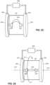
- Fig. 22 illustrates an example configuration of a portion of a propulsion system for heating propellant with an electric arc.
- a cylindrical chamber 2201 is closed at each end with metal end plates 2202 and 3.
- the chamber 2201 may be filled with gas (e.g., air at atmospheric pressure).
- Sliding electrical contacts 2204 and 2205 may provide electrical connections to a source of high voltage 2206.
- the end plates 2202 and 2203 may support conducting electrodes 2207 and 2208 respectively.
- the electrodes 2207 and 2208 may be positioned along the central axis of symmetry of the chamber 2201.
- the high voltage causes an electrical arc 2209 to strike between the electrodes 2207 and 2208. Due to buoyancy effects in gravity, the electrical arc 2209 may rise due to heating and have low stability, moving about when buffeted by air currents.
- An example source of high voltage 2206 may be configured to deliver up to 15 kV of 60 HZ alternating voltage at 450 watts into the electrical arc 2209.
- Fig. 23 illustrates the chamber 2201 together with end plates 2202 and 2203 set into rotational motion about a symmetry axis 2310, shown as a broken line.
- the direction of rotation is indicated by a curved arrow 2311.
- Moderate rotation rates e.g., 100-1000 rpm
- Buoyancy effects may cause dense cooler air to be forced away from the rotation axis while warmer less dense air may be focused along the axis of rotation.
- the hot electric arc 2209 may, consequently, be tightly focused along the axis of rotation.
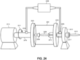
- FIG. 24 an example system configuration for rotating the chamber 2201 and adapting the chamber 2201 for propulsion are illustrated.
- Motor 2414 and shaft 2416 drive the rotational motion of the end plate 2203 and the chamber 2201.
- the electrical arc 2209 forms between the electrode 2208 and the input throat of a metal nozzle 2412.
- the end plate 2202 is supported by the hollow shaft 2417 and the support bearing 2415.
- the hollow shaft 2417 allows high velocity gas 2418 to exit the nozzle 2412 and produce thrust.
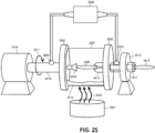
- Fig. 25 illustrates an example system for adding heat to the rotating the chamber 2201 for the purpose of producing vapor propellant from a liquid.
- the chamber 2201 may be partially filled with water 2519.
- the outer wall of chamber 2201 receives heat 2520 from combustion (e.g., of a solid fuel) or any suitable heat source 2521.
- the addition of heat 2520 may cause the water 2519 to boil, and the water vapor may serve as the gaseous propellant.
- High voltage from the voltage source 2206 may cause the electrical arc 2209 to form between electrode 2208 and nozzle 2412.
- the electrical arc 2209 in water vapor may be tightly focused directly into the throat of nozzle 2412.
- Fig. 26 illustrates a configuration for employing rotating thrusters in a spacecraft.
- any non-zero angular momentum may cause the spacecraft to rotate.
- two similar rotating thrusters 2622 and 2623 are caused to rotate simultaneously at similar rate but in opposite directions by counter rotating electric motors 2624 and 2625.
- the angular momentum contribution from the thrusters may be controlled (e.g., set to substantially zero).
- Slight mass imbalances between the two thrusters may be precisely compensated by controlling the differential speed of the driving motors 2624 and 2625 through electrical drive cables 2631.
- the two thrusters 2622 and 2623 may be intentionally operated at different rotation speeds for short periods of time in order to intentionally rotate the spacecraft to a new orientation.
- Fig. 27 illustrates a system for controlling water leakage from rotating thrusters (e.g., the thrusters 2622, 2623).
- Counter-rotating thrusters 2622 and 2623 are provided with an articulated support structure 2728 and end caps 2726 and 2727.
- the end caps 2726 and 2727 include compliant surface material which may be closed against the exhaust ports of the thrusters 2622 and 2623 to prevent water leakage.
- the end caps 2726 and 2727 may be opened or closed upon electrical command of the actuator 2730 through electrical drive cables 2731.
- the end caps 2726 and 2727 are further provided with bearings 2732 and 2733 which allow free rotation of the end caps 2726 and 2727 in the closed position.
- the two thrusters 2622 and 2623 may be operated at different rotation speeds with the end caps 26 and 27 in either open or closed position.
- Fig. 28 illustrates the system illustrated in Fig. 27 , but with the end caps 2726 and 2727 in the closed position.
- Bearings 2732 and 2733 allow free rotation of thrusters 2622 and 2623 and the end caps 2726 and 2727 in the closed position.
Landscapes
- Engineering & Computer Science (AREA)
- Chemical & Material Sciences (AREA)
- Combustion & Propulsion (AREA)
- Physics & Mathematics (AREA)
- Plasma & Fusion (AREA)
- General Engineering & Computer Science (AREA)
- Mechanical Engineering (AREA)
- Analytical Chemistry (AREA)
- Remote Sensing (AREA)
- Aviation & Aerospace Engineering (AREA)
- Electromagnetism (AREA)
- Plasma Technology (AREA)
- Constitution Of High-Frequency Heating (AREA)
Description
- The disclosure generally relates to operating a spacecraft and more specifically to improving efficiency and reliability of thrusters.
- This background description is provided for the purpose of generally presenting the context of the disclosure. Work of the presently named inventors, to the extent it is described in this background section, as well as aspects of the description that may not otherwise qualify as prior art at the time of filing, are neither expressly nor impliedly admitted as prior art against the present disclosure.
- With increased commercial and government activity in the near space, a variety of spacecraft and missions are under development. Multiple propulsion techniques are known, and today the spacecraft can implement several types of thrusters.
- One such type is microwave electrothermal thruster (METs), based on a method of electrical propulsion that uses a microwave power source to generate and heat a plasma contained within a resonant chamber or resonant cavity. Generally speaking, the microwave energy is provided to the chamber by means of a probe (sometimes referred to as an "antenna") or a waveguide. This microwave energy raises the temperature of a gaseous propellant and provides thrust in the form of hot gases exiting the chamber through a nozzle.
- Existing forms of microwave electrothermal thrusters have been tested in research universities. These prototypes reveal multiple inefficiencies such as those related to the transfer of microwave power to the resonant cavity, the loss of thermal energy to the nozzle of the system, issues with low-power efficiency, etc.
- Further, MET thrusters generally are not expected to provide the same amount of thrust as chemical propulsion thrusters which utilize a reduction-oxidation reaction to generate a hot gas that exits via a nozzle and generates thrust.
- D J Sullivan ET AL present the preliminary tests and performance of a prototype microwave electrothermal thruster in the academic paper "Development of a Microwave Resonant Cavity Electrothermal Thruster Prototype". The primary component of the device is a microwave resonant cavity and the relevant electromagnetic theory as it relates to the choice of the design of the cavity. The device is said to produce stable axial plasmas within a pressurized section of the cavity with the plasma positioned in the inlet region of the nozzle. Plasma stability is said to be enhanced by axial power coupling, an optimal distribution of electric power density within the cavity and a propellant gas flow which has a large vortical velocity component. D. SULLIVAN ET AL present a microwave arcjet thruster utilizing microwave energy to create a free-floating plasma discharge within the microwave resonant cavity in the academic paper "Performance Testing and Exhaust Plume Characterization of the Microwave Arcjet Thruster". Michael M. Micci presents the performance of a low-power microwave thruster in the academic paper "Low-Power Solid-State Microwave Thruster Systems". Further, Micci presents that when the low-power microwave thruster is combined with a solid-state microwave source, obviating the need for a power processing unit, the low-power microwave thruster system was found to have significant advantages over other low-power electric propulsion thrusters.
- Generally speaking, the techniques of this disclosure improve the efficiency and reliability of a thruster system operating in a spacecraft. The scope of the invention is defined by the appended claims.
-
-
Fig. 1 is a block diagram of an example spacecraft in which the techniques of this disclosure can be implemented; -
Fig. 2 illustrates an example thruster system that can operate in the spacecraft ofFig. 1 ; -
Fig. 3A is a block diagram of an example source of microwave power that includes multiple microwave generators, and that can power one or more thrusters, in a redundant and/or combined manner; -
Fig. 3B schematically illustrates an example placement of multiple microwave generators relative to a load; -
Fig. 4 is a block diagram of an example thruster system which a propellant compartment is disposed through a waveguide, so as to eliminate the need for a dedicated resonant cavity; -
Fig. 5 is a block diagram of an example thruster system in which a propellant is injected into a coaxial transmission line; -
Fig. 6A schematically illustrates placement of magnets along the walls of the cylindrical housing of the resonant cavity to cooperate with one or more ferrite inserts disposed inside the resonant cavity and automatically tune the resonant cavity; -
Fig. 6B schematically illustrates placement of magnets at the base of the cylindrical housing of the resonant cavity to cooperate with one or more ferrite inserts disposed inside the resonant cavity and automatically tune the resonant cavity; -
Fig. 7A illustrated an example coupling of microwave energy into a resonant cavity using a waveguide that abuts the base of the cylindrical housing of the resonant cavity; -
Fig. 7B illustrated an example coupling of microwave energy into a resonant cavity using a waveguide that abuts the wall of the cylindrical housing of the resonant cavity along at least a portion of the circumference of the cylindrical housing; -
Fig. 8A is a perspective view of an example resonant cavity with an annular structure that extends into the resonant cavity along the thrust axis to support injectors of the propellant; -
Fig. 8B is a perspective view of an example resonant cavity in which capillaries are used to deliver propellant into the resonant cavity; -
Fig. 8C is a perspective view of an example resonant cavity in which capillaries are used to deliver propellant into the resonant cavity, and an annular structure extends into the resonant cavity along the thrust axis to improve vorticity; -
Fig. 9A illustrates an example geometry of a resonant cavity in which the varying diameter improves vorticity of the hot gas; -
Fig. 9B illustrates another example geometry of a resonant cavity in which the diameter varying along two sections improves vorticity of the hot gas; -
Fig. 10A illustrates an example monolithic nozzle disposed in a top plate of a resonant cavity; -
Fig. 10B illustrate an example configuration in which a nozzle insert extends into the cavity to increase the intensity of the electric field that acts upon the propellant; -
Fig. 11 illustrates an example configuration in which concentric annular inserts, made of materials with different coefficients of thermal expansion, reduce thermal stress exerted on the throat of the nozzle; -
Fig. 12A illustrates an example nozzle adapter for simplifying the testing of various nozzles in a thruster system; -
Fig. 12B illustrates the nozzle adapter ofFig. 12B mated with the top plate of a resonant cavity; -
Fig. 13 illustrates an example nozzle insert which can be used to protect the throat of a nozzle; -
Fig. 14A is a block diagram of an example configuration in which a coating mix for depositing a coating material onto the inner surface of a nozzle can be injected into a resonant cavity during manufacturing; -
Fig. 14B is a block diagram of an example configuration in which a coating mix for depositing a coating material onto the inner surface of a nozzle can be injected into a resonant cavity in a certain operational mode of the thruster; -
Fig. 14C is a block diagram of an example configuration in which a coating mix for depositing a coating material onto the inner surface of a nozzle can be injected into a resonant cavity along with the propellant; and -
Fig. 15 illustrates power output of a microwave generator and a rate at which a propellant is injected into a cavity, plotted on a shared timeline, according to an example operation of a thruster system of this disclosure. -
Fig. 16 illustrates a cross section view of an embodiment of a microwave electro-thermal (MET) thruster. -
Fig. 17 is a perspective schematic view of the microwave fields inside the thruster. -
Fig. 18 illustrates details of the gas injectors in the first embodiment. -
Fig. 19 illustrates additional details of the gas injectors in the first embodiment. -
Fig. 20 illustrates a cross section of another embodiment of a MET thruster. -
Fig. 21 illustrates details of the gas injectors in the embodiment ofFig. 20 . -
Fig. 22 is a schematic view of one embodiment of a chamber of a propulsion assembly with a plasma discharge. -
Fig. 23 is a schematic illustration of the assembly ofFig. 22 illustrating stabilization of the plasma discharge by rotation. -
Fig. 24 is a schematic illustration of a rotational mounting of the propulsion assembly. -
Fig. 25 is a schematic illustration of the assembly in which heat is added to the rotating chamber. -
Fig. 26 is a schematic illustration of a dual counter-rotational assembly of thrusters for integrating into an example spacecraft. -
Fig. 27 illustrates additional details, including nozzle caps, of the dual thruster arrangement ofFig. 26 . -
Fig. 28 illustrates the dual thruster arrangement ofFig. 27 with nozzle caps closing the nozzles. - [0069a] The following detailed description provides a plurality of embodiments, examples and implementations of which only the embodiments of
Fig. 8A ,Fig. 16-19 as well asFig. 21 and22 are according to the invention as defined by the appended claims. The other embodiments, examples and implementations are not according to the invention per se but useful for understanding the invention. - A spacecraft of this disclosure may be configured for transferring a payload from a lower energy orbit to a higher energy orbit according to a set of mission parameters. The mission parameters may include, for example, a time to complete the transfer and an amount of propellant and/or fuel available for the mission. Generally, the spacecraft may collect solar energy and use the energy to power one or more thrusters. Different thruster types and/or operating modes may trade off the total amount of thrust with the efficiency of thrust with respect to fuel or propellant consumption, defined as a specific impulse.
- Commercial economic activity in near-earth space and in regions beyond is growing rapidly. In the inner solar system, ample and continuous electric power is available through solar cell collectors on spacecraft. There may be an efficiency advantage to using solar-electric power for spacecraft propulsion. Also, electric heating of propellant gasses may eliminate the need for caustic or dangerously explosive bi-propellant fuels. Simple lightweight molecules may serve as high specific-impulse propellants. These include: hydrogen, water, ammonia, carbon dioxide, and cryogenic liquids such as liquid helium or argon.
- In spacecraft propulsion systems, efficient use of propellant may enable better mission parameters (e.g., faster or more payload). In general, chemical systems deliver the highest thrust but have the lowest propellant efficiency, as measured by specific impulse. Once a spacecraft is free of atmospheric drag, it is often desirable to use a low-thrust high specific-impulse electric thrusters rather than lower specific-impulse chemical thrusters. While mission times may be longer with low thrust propulsion, the total mission range can be substantially extended by using high specific impulse systems. In electro thermal propulsion, electric power is used to directly heat propellant gasses to higher temperatures than can be reached with chemical systems, thereby improving specific impulse.
- The spacecraft in some implementations includes thrusters of different types to improve the efficiency of using solar energy when increasing orbital energy. In some implementations, the spacecraft uses the same subsystems for operating the different-type thrusters, thereby reducing the mass and/or complexity of the spacecraft, and thus decreasing mission time while maintaining and/or improving reliability. Additionally or alternatively, the spacecraft can choose or alternate between thrusters of different types as primary thrusters. The spacecraft can optimize these choices for various mission goals (e.g., different payloads, different destination orbits) and/or mission constraints (e.g., propellant availability). Example optimization of these choices can include variations in collecting and storing solar energy as well as in controlling when the different thrusters use the energy and/or propellant, as discussed below.
-
Fig. 1 is a block diagram of aspacecraft 100 configured for transferring a payload between orbits. Thespacecraft 100 includes several subsystems, units, or components disposed in or at ahousing 110. The subsystems of thespacecraft 100 may include sensors andcommunications components 120,mechanism control 130,propulsion control 140, aflight computer 150, a docking system 160 (for attaching to alaunch vehicle 162, one ormore payloads 164, apropellant depot 166, etc.), apower system 170, athruster system 180 that includes afirst thruster 182 and asecond thruster 184, and apropellant system 190. Furthermore, any combination of subsystems, units, or components of thespacecraft 100 involved in determining, generating, and/or supporting spacecraft propulsion (e.g., themechanism control 130, thepropulsion control 140, theflight computer 150, thepower system 170, thethruster system 180, and the propellant system 190) may be collectively referred to as a propulsion system of thespacecraft 100. - The sensors and
communications components 120 may several sensors and/or sensor systems for navigation (e.g., imaging sensors, magnetometers, inertial motion units (IMUs), Global Positioning System (GPS) receivers, etc.), temperature, pressure, strain, radiation, and other environmental sensors, as well as radio and/or optical communication devices to communicate, for example, with a ground station, and/or other spacecraft. The sensors andcommunications components 120 may be communicatively connected with theflight computer 150, for example, to provide theflight computer 150 with signals indicative of information about spacecraft position and/or commands received from a ground station. - The
flight computer 150 may include one or more processors, a memory unit, computer readable media, to process signals received from the sensors andcommunications components 120 and determine appropriate actions according to instructions loaded into the memory unit (e.g., from the computer readable media). Generally, theflight computer 150 may be implemented any suitable combination of processing hardware, that may include, for example, applications specific integrated circuits (ASICs) or field programmable gate arrays (FPGAs), and/or software components. Theflight computer 150 may generate control messages based on the determined actions and communicate the control messages to themechanism control 130 and/or thepropulsion control 140. For example, upon receiving signals indicative of a position of thespacecraft 100, theflight computer 150 may generate a control message to activate one of thethrusters thruster system 180 and send the message to thepropulsion control 140. Theflight computer 150 may also generate messages to activate and direct sensors andcommunications components 120. - The
docking system 160 may include a number of structures and mechanisms to attach thespacecraft 100 to alaunch vehicle 162, one ormore payloads 164, and/or apropellant refueling depot 166. Thedocking system 160 may be fluidicly connected to thepropellant system 190 to enable refilling the propellant from thepropellant depot 166. Additionally or alternatively, in some implementations at least a portion of the propellant may be disposed on thelaunch vehicle 162 and outside of thespacecraft 100 during launch. The fluidic connection between thedocking system 160 and thepropellant system 190 may enable transferring the propellant from thelaunch vehicle 162 to thespacecraft 100 upon delivering and prior to deploying thespacecraft 100 in orbit. - The
power system 170 may include components (discussed in the context ofFigs. 4-7 ) for collecting solar energy, generating electricity and/or heat, storing electricity and/or heat, and delivering electricity and/or heat to thethruster system 180. To collect solar energy into thepower system 170, solar panels with photovoltaic cells, solar collectors or concentrators with mirrors and/or lenses, or a suitable combination of devices may collect solar energy. In the case of using photovoltaic devices, thepower system 170 may convert the solar energy into electricity and store it in energy storage devices (e.g, lithium ion batteries, fuel cells, etc.) for later delivery to thethruster system 180 and other spacecraft components. In some implementations, thepower system 180 may deliver at least a portion of the generated electricity directly to thethruster system 180 and/or to other spacecraft components. When using a solar concentrator, thepower system 170 may direct the concentrated (having increased irradiance) solar radiation to photovoltaic solar cells to convert to electricity. In other implementations, thepower system 170 may direct the concentrated solar energy to a solar thermal receiver or simply, a thermal receiver, that may absorb the solar radiation to generate heat. Thepower system 170 may use the generated heat to power a thruster directly, as discussed in more detail below, to generate electricity using, for example, a turbine or another suitable technique (e.g., a Stirling engine). Thepower system 170 then may use the electricity directly for generating thrust or store electric energy as briefly described above, or in more detail below. - The
thruster system 180 may include a number of thrusters and other components configured to generate propulsion or thrust for thespacecraft 100. Thrusters may generally include main thrusters that are configured to substantially change speed of thespacecraft 100, or as attitude control thrusters that are configured to change direction or orientation of thespacecraft 100 without substantial changes in speed. In some implementations, thefirst thruster 182 and thesecond thruster 184 may both be configured as main thrusters, with additional thrusters configured for attitude control. Thefirst thruster 182 may operate according to a first propulsion technique, while thesecond thruster 184 may operate according to a second propulsion technique. - For example, the
first thruster 182 may be a microwave-electro-thermal (MET) thruster (also may be referred to as a MET rocket). In a MET thruster cavity, an injected amount of propellant may absorb energy from a microwave source (that may include one or more oscillators) included in thethruster system 180 and, upon partial ionization, further heat up, expand, and exit the MET thruster cavity through a nozzle, generating thrust. - The
second thruster 184 may be a solar thermal thruster. In one implementation, propellant in a thruster cavity acts as the solar thermal receiver and, upon absorbing concentrated solar energy, heats up, expands, and exits the nozzle generating thrust. In other implementations, the propellant may absorb heat before entering the cavity either as a part of the thermal target or in a heat exchange with the thermal target or another suitable thermal mass thermally connected to the thermal target. In some implementations, while the propellant may absorb heat before entering the thruster cavity, thethruster system 180 may add more heat to the propellant within the cavity using an electrical heater or directing a portion of solar radiation energy to the cavity. - The
propellant system 190 may store the propellant for use in thethruster system 180. The propellant may include water, hydrogen peroxide, hydrazine, ammonia or another suitable substance. The propellant may be stored on the spacecraft in solid, liquid, and/or gas phase. To that end, thepropellant system 190 may include one or more tanks. To move the propellant within thespacecraft 100, and to deliver the propellant to one of the thrusters, the propellant system may include one or more pumps, valves, and pipes. As described below, the propellant may also store heat and/or facilitate generating electricity from heat, and thepropellant system 190 may be configured, accordingly, to supply propellant to thepower system 170. - The
mechanism control 130 may activate and control mechanisms in the docking system 160 (e.g., for attaching and detaching payload or connecting with an external propellant source), the power system 170 (e.g., for deploying and aligning solar panels or solar concentrators), and/or the propellant system (e.g., for changing configuration of one or more deployable propellant tanks). Furthermore, themechanism control 130 may coordinate interaction between subsystems, for example, by deploying a tank in thepropellant system 190 to receive propellant from an external source connected to thedocking system 160. - The
propulsion control 140 may coordinate the interaction between thethruster system 140 and thepropellant system 190, for example, by activating and controlling electrical components (e.g., a microwave source) of thethruster system 140 and the flow of propellant supplied to thrusters by thepropellant system 190. Additionally or alternatively, thepropulsion control 140 may direct the propellant through elements of thepower system 170. For example, thepropellant system 190 may direct the propellant to absorb the heat (e.g., at a heat exchanger) accumulated within thepower system 170. Vaporized propellant may then drive a power plant (e.g., a turbine, a Stirling engine, etc.) of thepower system 170 to generate electricity. Additionally or alternatively, thepropellant system 190 may direct some of the propellant to charge a fuel cell within thepower system 190. - The subsystems of the spacecraft may be merged or subdivided in different implementations. For example, a single control unit may control mechanisms and propulsion. Alternatively, dedicated controllers may be used for different mechanisms (e.g., a pivot system for a solar concentrator), thrusters (e.g., a MET thruster), valves, etc. In the following discussion, a controller may refer to any portion or combination of the
mechanism control 130 and/orpropulsion control 140. -
Fig. 2 illustrates aMET thruster system 280 operating within aspacecraft system 210 that also includes acontroller 240, apower system 270, and apropellant system 290. TheMET thruster system 280 includes aresonant cavity 281 with athrust axis 277, separated into apropellant compartment 282a and amicrowave coupling compartment 282b. Theresonant cavity 281 also can be referred to as a chamber (e.g., propulsion chamber, resonant chamber, etc.) or a resonator. Relative to a nominal orientation of thethruster 281, thepropellant compartment 282a may be referred to as an upper cavity, and themicrowave coupling compartment 282b may be referred to as a lower cavity. Theresonant cavity 281 extends between atop plate 283a and abottom plate 283b, and is separated into the twocompartments 282a,b by adielectric window 284. Anozzle 285 may be disposed trough thetop plate 283a, with thetop plate 283a substantially surrounding thenozzle 285. Apropellant injection structure 286 may be disposed at thetop plate 283a (e.g., included into an annular structure that extends into the cavity 281) or at another suitable location in thepropellant compartment 282a. Thepropellant injection structure 286 may be fluidicly coupled to thepropellant system 290 via asupply line 292. Theinjection structure 286 may include one or more injectors configured to inject propellant into thepropellant compartment 282a of theresonant cavity 281 so as to create a rotating circumferential flow. - The resonant cavity may be made of metal or another suitable material. In some implementations, the resonant cavity may be made of a ceramic material with a metal coating in order to improve thermal and conductive properties.
- The
microwave coupling compartment 282b of theresonant cavity 281 may electromagnetically couple via acoupling structure 287 to amicrowave source 288. In some implementations, thecoupling structure 287 couples energy into thecavity 281 via an evanescent electromagnetic field. The microwave source may include one or more microwave generators or oscillators (e.g., magnetrons, solid-state Colpitts circuits, etc.), amplifiers, phase controllers, switches, and/or other suitable microwave circuits and devices. Combining multiple oscillators in amicrowave source 288 is discussed in reference toFigs. 3A and 3B . Themicrowave coupling structure 287 may include a coaxial cable terminated with a probe or an antenna, or a waveguide terminated with one or more apertures to couple electromagnetic energy generated by themicrowave source 288 to a mode (or multiple modes) of theresonant cavity 281. Furthermore, the coupling structure may include impedance matching or tuning elements (e.g., stubs, quarter-wave transformers, etc.). Example coupling structures are discussed with reference toFigs. 6A,B and 7A,B . By way of thecoupling structure 287, themicrowave source 288 generates standing waves with spatial power distribution defined by the excited modes in theresonant cavity 281. - In operation of the
thruster system 280, the power delivered to the mode(s) of theresonant cavity 281 may ionize a portion of the injected propellant, creating plasma that subsequently absorbs more electromagnetic energy. The energy absorbed by the plasma heats the surrounding propellant that increases in temperature and pressure and escapes thepropellant compartment 282a through thenozzle 285 to generate thrust. Substantially confining the plasma to a suitable region near an inlet of thenozzle 285 increases efficiency of thethruster system 280. One way of confining the plasma is to introduce rotating circumferential flow of the injected propellant, as briefly discussed above and, in more details with reference toFigs. 8A, 8B . - Alternative implementations of the
thruster system 210 may not include a resonant cavity 281 (e.g., as discussed with reference toFig. 4 ) or may integrate the resonant cavity into the coupling structure 287 (e.g., as discussed with reference toFig. 5 ). - In some implementations, the
thruster system 280 may be implemented at least in part on a circuit board, with integrated and discrete components. Solid-state oscillators may be used to implement themicrowave source 288. Micro-strip and coplanar or other suitable transmission lines can implement thecoupling 287, and at least a portion of thepropellant cavity 281 may be etched through the circuit board. - Further, in some implementations, additional components may surround the portion of the
nozzle 285 outside theresonant cavity 281. The components may be configured for further heating the gas exiting thenozzle 285 and/or for directing the flow of the exiting gas by static or electric or magnetic field. In this manner, the thruster can improve specific thrust ISP - In some implementations, the
MET thruster system 280 can be configured to operate in a MET mode as well as a chemical propulsion mode. When operating in the chemical propulsion mode, theMET thruster system 280 can generate thrust by forming a hot gas in thecavity 281 using a reduction-oxidation reaction between a first fluid (e.g., hydrozene) and a second fluid (e.g., hydrogen peroxide). The first and second fluids can operate as reducing and oxidizing agents, respectively. Moreover, the same fluid (e.g., hydrozene) can function as the propellant in the MET mode of operation as well as one of the agents in the chemical mode of operation. Still further, theMET thruster system 280 in some implementations can employ fuel cells that store oxygen and hydrogen separately, and thus the same fluid, water, can be used as a propellant ion the MET mode of operation and as a source of the reducing and oxidizing agents in the chemical mode of operation. -
Fig. 3A illustrates an architecture for directing signals from multiple microwave oscillators or generators to one or more MET thrusters. The example architecture includes four generators 31 0a-d, each generating a respective signal. The signals may be substantially continuous wave (CW) signals in the range of 1-20 GHz. In some implementations, the signals may have substantially different frequencies (e.g., with frequency differences no less than 1 kHz, 10 kHz, 100 kHz or another suitable minimum difference). In other implementations, the signals may have substantially similar frequencies (e.g., with frequency differences less than 1 kHz, 100 Hz, 10 Hz or another suitable minimum difference). The architecture 300 may includephase adjustment components 320a-d configured to adjust the phase of each of the corresponding signals corresponding to each of thegenerators 310a-d. The architecture 300 may then direct the phase-shifted signals to aswitching network 330. The switching network 340 may include a suitable number of routing devices, including splitters, combiners, electro-mechanical switches, micro-electro-mechanical system (MEMS) switches, solid state switches, etc. The switching network 340 may provide an output to one of twoMET thrusters 350a,b. In some implementations, only one MET thruster may be used, while more than two MET thrusters may be used in other implementations. - Some of the generators 31 0a-d may be configured to phase-lock to generate signals of substantially the same frequency and with substantially consistent pair-wise phase differences between phase difference between phase-locked generators. In some implementations, the
phase adjustment components 320a-d may be filters. In other implementations, thephase adjustment components 320a-d may be delay lines. In either case, the phase-adjustment components 320a-d may be tunable. In some implementations, a controller adjusts the phases of thecomponents 320a-d to facilitate phase-locking or to increase the power output of the combined signals. - The switching network 340 may direct output to a single MET thruster (i.e., coupling energy into the resonant cavity of the MET thruster). In other implementations, the switching network may direct one portion of the output to one thruster and another portion of the output to another thruster. In a redundant MET thruster system that includes
multiple microwave generators 310a-d andmultiple MET thrusters 350a,b, the switching network 340 may direct a subset of the signals generated by thegenerators 310a-d, to one or both of theMET thrusters 350a,b. -
Fig. 3B illustrates an example three-dimensional placement of microwave oscillators orgenerators 360a-d relative to aload 370, which can be the resonant cavity, for example (such as theresonant cavity 281 discussed with reference toFig. 2 ). Thegenerators 360a-d are interconnected via respective transmission or wave guides 380a-d. The lengths of theguides 380a-d can be adjusted so that thegenerators 360a-d are phase-locked and configured to increase the power delivered to theload 370. -
Fig. 4 illustrates aMET thruster configuration 400 that does not require a resonant cavity. Instead, themicrowave source 410 delivers energy via awaveguide 420 to apropellant compartment 430 disposed through thewaveguide 420. Thepropellant compartment 430 includes anozzle 432. The microwave energy delivered to thepropellant compartment 430 ignites a plasma and heats the gaseous propellant that generates thrust by expanding through thenozzle 432. A power system 470 (e.g., thepower system 270 ofFig. 2 ) may supply energy to themicrowave source 410, while a propellant system 490 (e.g., the propellant system 290) may supply the propellant to thepropellant compartment 430. Thus, theMET thruster configuration 400 may operate within thespacecraft system 210. -
Fig. 5 illustrates anotherMET thruster configuration 500. Themicrowave source 510 delivers energy via acoaxial transmission line 520 to apropellant compartment 530 disposed between a center conductor and a shield (an outer conductor) of a section of thecoaxial transmission line 520. The microwave energy delivered to thepropellant compartment 530 ignites a plasma and heats the gaseous propellant that generates thrust by expanding through thenozzle 532. A power system 570 (e.g., thepower system 270 ofFig. 2 ) may supply energy to themicrowave source 510, while a propellant system 590 (e.g., the propellant system 290) may supply the propellant to thepropellant compartment 530. A section of the coaxial transmission line proximal to thenozzle 532 and including thepropellant compartment 530 may form a resonance cavity. In some implementations, a section of thecoaxial transmission line 520 may include an impedance transformation section with coaxial stubs, quarter-wave impedance transformer, or another suitable impedance matching circuit. The center conduct of thecoaxial transmission line 520 within thepropellant compartment 530 may be coated with a dielectric material to protect it from degradation caused by plasma. Further, thecoaxial transmission line 520 can include a dielectric window to define the propellant compartment 530 (i.e., separate a one portion of the coaxial transmission line from another portion of the coaxial transmission line in which the hot gas is contained). - Now referring to a
configuration 600 ofFig. 6A , a MET thruster of this disclosure in some implementations includes a resonant cavity 601 (which can be similar to theresonant cavity 281 discussed above and include adielectric window 605 separating the cavity into two compartments), the resonant frequency of which a controller (e.g., thecontroller 240 ofFig. 2 ) can tune. In particular, to counteract the impact of the plasma generated within theresonant cavity 601 during operation of the MET thruster on the resonant frequencies of theresonant cavity 601, one ormore magnets 602 exert a magnetic bias onto aferrite insert 604 disposed inside theresonant cavity 601. In the example implementation ofFig. 6A , the one ormore magnets 602 are electromagnets which the controller can activate and deactivate as needed. - For example, the
controller 240 can activate the electromagnet(s) 602 when at least a portion of the propellant inside theresonant cavity 601 is ionized. As discussed in more detail with reference toFig. 15 below, the propellant entering theresonant cavity 601 at an initial stage of operating the MET thruster can heat up and remain unionized until a certain time (and, at a time T3 inFig. 15 ), when the propellant begins to form plasma and accordingly begin to impact the resonant frequencies of theresonant cavity 601. Thecontroller 240 can determine this time using temperature sensors disposed in or near theresonant cavity 601 or, in another implementation, by determining the amount of time elapsed since the propellant began entering the resonant cavity at a certain flowrate and using a look-up table to determine when thecontroller 240 should activate theelectromagnets 602. - In the implementation of
Fig. 6A , the one ormore magnets 602 are disposed along the vertical wall of the cylindrical housing of the resonant cavity 601 (with the position of anozzle 610 defining the vertical orientation of the resonant cavity 601). The corresponding ferrite insert(s) 604 are disposed inside theresonant cavity 601, along the vertical wall of the cylindrical housing, so that the vertical wall of theresonant cavity 601 separates each of the one ormore magnets 602 from the correspondingferrite insert 604. A waveguide 620 couples microwave energy to theresonant cavity 601 at the base of the cylindrical housing of theresonant cavity 601. - On the other hand, in the
configuration 650 ofFig. 6B , the one ormore magnets 652 are disposed outside the base of the cylindrical housing of the resonant cavity 651 (which also can be similar to theresonant cavity 281 discussed above and can include a dielectric window 655), at an end opposite to the end at which the nozzle 660 is disposed. Theferrite insert 654 is disposed inside theresonant cavity 651 at the base of the cylindrical housing, so that the plate at the base of theresonant cavity 651 separates each of the one ormore magnets 652 from the correspondingferrite insert 654. Awaveguide 670 couples microwave energy to theresonant cavity 651 at a vertical wall of the cylindrical housing of theresonant cavity 651. - In some implementations, a MET thruster implements a combination of the techniques of
Figs. 6A and 6B . More generally, a MET thruster can include one or more ferrite inserts at any suitable locations within the resonant cavity and one or more magnets disposed at the suitable corresponding locations outside the resonant cavity. Moreover, in the some implementations the magnets can be permanent (e.g., rare earth magnets) mechanically actuated to interact with the ferrite inserts. - Next, several example techniques for coupling microwave energy to a propellant in a resonant cavity are discussed next with reference to
Figs. 7A and 7B . - Referring first to a
configuration 700 ofFig. 7A , aresonant cavity 701 includes adielectric window 705 and is disposed within a cylindrical housing, similar to theresonant cavity 281 discussed above. Awaveguide 720 abuts the base of the cylindrical housing, at an end opposite to the end where a nozzle 710 is disposed. Thewaveguide 720 can have a rectangular cross-section for example. Thewaveguide 720 couples electromagnetic energy from a microwave source, such as themicrowave source 288 ofFig. 2 , into theresonant cavity 701 via anaperture 730. In this implementation, theaperture 730 has a round shape. - According to the
configuration 750 ofFig. 7B , aresonant cavity 751 also includes adielectric window 755 and is disposed within a cylindrical housing, similar to theresonant cavity 281 discussed above. However, awaveguide 770 wraps around at least a portion of the circumference of the cylindrical housing. Thewaveguide 770 thus abuts the vertical wall of the cylindrical housing. Thewaveguide 770 includes an aperture in the shape of a narrow slit, with the longer dimension of the slit parallel to the axis of the resonant cavity 751 (i.e., the axis of the cylindrical housing). - In some implementations, the
waveguide 770 includes multiple apertures in the section that abuts the cylindrical housing of theresonant cavity 751, so as to increase coupling efficiency. For example, thewaveguide 770 can include two, three, four, etc. apertures shaped similar to theaperture 780, via each of which the microwave source can deliver microwave energy into theresonant cavity 751. - In yet other implementations, a waveguide similar to the
waveguide - Now referring to
Fig. 8A , an exampleresonant cavity 801 includes anannular structure 810 that extends into theresonant cavity 801 along thethrust axis 803 to support or include one or more injectors 820. In this implementation, two injectors 820A and 820B are separated from each other by 180 degrees along a circumference concentric with the circumference of the annular structure. In other implementation, theannular structure 810 supports four injectors, separated by each other by 60 degrees. More generally, theannular structure 810 can support N injectors, which can be separated from each other by 360/N degrees (or another suitable angular distance). - The
annular structure 810 in this implementation does not extend above atop plate 830 which supports anozzle 832. Theannular structure 810 in other implementations can extend above thetop plate 830. As a more particular example, theannular structure 810 can form an exit cone of thenozzle 832. In other implementations, thenozzle 832 has an integral structure, including an exit cone, and is provided separately of theannular structure 810. - In any case, the
annular structure 810 can include channels extending from the respective inlets 822A and 822B into thecavity 801 to define injectors 820A and 820B, or the channel can receive hollow tubes of the injectors 820A and 820B. The injectors 820A and 820B are configured to create or improve a rotating circumferential flow of the hot gas in thecavity 801. To this end, theannular structure 810 can define a suitable geometry for the injectors 820A and 820B, e.g., curve the channels of the injectors 820A and 820B so that the propellant enters thecavity 801 at an angle relative to thethrust axis 803, or provide substantially straight channels at an angle to thethrust axis 803. In this manner, the injectors 820A and 820B impart angular momentum to the propellant entering thecavity 801, which in turns facilitates the creation of a rotatingcircumferential flow 840 of hot gas in thecavity 801. Theannular structure 810 can orient the outlets 824A and 824B so that the injectors 824A and 824B impart angular momentum to the propellant along the same direction, e.g., clockwise as illustrated inFig. 8A or counterclockwise. - Further, as illustrated in
Fig. 8A , theannular structure 810 defines the location of outlets 824A and 824B of the injectors 820A and 820B, respectively. In particular, theannular structure 810 determines the respective locations of the outlets 824A and 824B in terms of a distance along thethrust axis 803 as well as in terms of a radial distance along a perpendicular to thethrust axis 803. Theannular structure 810 thus can facilitate injection of the propellant close to the location within thecavity 801 where plasma is formed (rather than near thetop plate 830 for example). - With continued reference to
Fig. 8A , theannular structure 810 in an example implementation includes a section 850 with a radius that increases with the distance away from thenozzle 832. The section 850 thus is shaped as a conical frustum to further improve vorticity and facilitate the creation of a rotating circumferential flow of hot gas. -
Fig. 8B illustrates an exampleresonant cavity 861 in which the injectors 870A and 807B are implemented as capillaries. In this implementation, the capillaries are not supported by an annular structure, and the point at which propellant enters theresonant cavity 861 is defined by the shape and the material of the capillaries. Similar to the implementation ofFig. 8A , the injectors 870A and 807B can impart angular momentum to the propellant entering thecavity 861, which in turns facilitates the creation of a rotating circumferential flow of hot gas in thecavity 861. -
Fig. 8C illustrates an exampleresonant cavity 881 in which injectors 890A are 890B are implemented as capillaries disposed outside anannular structure 880 which, similar to theannular structure 810 ofFig. 8A , extends into theresonant cavity 881. - Next,
Figs. 9A and 9B illustrate several example geometries of a resonant cavity, which can be used as theresonant cavity 281 in the MET thruster ofFig. 2 , for example. Theresonant cavity 901 includes abottom section 910, amiddle section 912, and atop section 914 most proximate to anozzle 920. In this implementation, thebottom section 910 and thetop section 914 have a constant diameter, but thebottom section 910 has a wider diameter than thetop section 914. Themiddle section 912 has a diameter that decreases along the cylinder axis, so that the portion of themiddle section 912 closer to thenozzle 920 is narrower than the portion of themiddle section 912 farther away from thenozzle 920. In this implementation, diameter decreases linearly, and themiddle section 912 forms a conical frustum which can improve vorticity and facilitate the creation of a rotating circumferential flow of hot gas. More generally, the diameter need not vary linearly and can vary in any suitable manner (e.g., exponentially). - In the implementation of
Fig. 9B , theresonant cavity 951 includes abottom section 960, a firstconical frustum section 962, amiddle section 964, a secondconical frustum section 964, and atop section 968 most proximate to anozzle 970. Thebottom section 960 and thetop section 968 have the same constant diameter. Themiddle section 964 has a constant diameter smaller than the diameter of thebottom section 960 and thetop section 968. The diameter of the firstconical frustum section 962 decreases along the cylinder axis, so that the portion closer to thenozzle 970 is narrower than the portion farther away from thenozzle 970. The diameter of the secondconical frustum section 966 increases along the cylinder axis, so that the portion closer to thenozzle 970 is wider than the portion farther away from thenozzle 970. The diameter can vary non-linearly in other implementations of thesection 962 and/or thesection 966. The geometry of theresonant cavity 951 also can improve vorticity and facilitate the creation of a rotating circumferential flow of hot gas. - Now referring to
Fig. 10A , an examplemonolithic nozzle 1000 can be disposed in atop plate 1002 of a resonant cavity, such as the resonant cavity of 281 illustrated inFig. 2 . Theentire nozzle 1000 can be made of the same material such as a ceramic, for example, or metal with ceramic coating. Thenozzle 1000 can include aflange 1010 via which thenozzle 1000 attaches to thetop plate 1002. Theflange 1010 prevents thenozzle 1000 from being expelled due to pressure inside the resonant cavity. - In the implementation of
Fig. 10B , an examplemonolithic nozzle 1050 similarly can be disposed in atop plate 1052 of a resonant cavity. Theentire nozzle 1050 can be made of the same material. In this implementation, aportion 1060 of thenozzle 1060 extends into the resonant cavity to increase the intensity of the electric field that acts upon the propellant. The portion that extends into the cavity can prevents thenozzle 1060 from being expelled due to pressure inside the resonant cavity, similar to theflange 1010 of thenozzle 1000 discussed above. - Next,
Fig. 11 illustrates anexample configuration 1100 in which concentric annular inserts 112 and 114 in atop plate 1102 surround anozzle 1110. AlthoughFig. 11 illustrates two concentric annular inserts, in other implementations a single concentric annular insert is used or, conversely, more than two such inserts are used. - The
top plate 1102 can be disposed at an end of a resonant cavity (e.g., theresonant cavity 281 discussed above). Thetop plate 1102 can be made of a certain material, such as steel or another suitable metal alloy or metal, with a first coefficient of thermal expansion (CTE) α1. The CTE of the material of the nozzle can be α2 different from α1. For example, thenozzle 1110 can be made of a ceramic material with a lower CTE than metal, or thenozzle 1110 can have a ceramic coating. Because the temperature may not distribute evenly through thetop plate 1102 when plasma has formed in the resonant cavity, with areas closer to thenozzle 1110 heating up more than areas near the outer edge of thetop plate 1102, thetop plate 1102 may exert pressure on thenozzle 1110, which over time may lead to deterioration of thenozzle 1110. For example, the throat of thenozzle 1110 may get narrower or uneven. - In some implementations, the concentric
annular insert 1112 is disposed between thenozzle 1110 and the top plate 1102 (directly adjacent to thetop plate 1102 or adjacent via another one or more annular concentric inserts). The concentricannular insert 1112 has a coefficient of thermal expansion α3 different from α2 and α1. In an example implementation, α3 is smaller than α2 and α1. As a result, the concentricannular insert 1112 reduces the thermal stress which thetop plate 1102 exerts on thenozzle 1110 and, in particular, on the throat of the nozzle. In another implementation, the CTE α3 is smaller than α1 but equal to or greater than α3. In yet another implementation, the concentricannular insert 1112 is made of an elastic material to absorb the stress exerted by thetop plate 1102. - When multiple concentric annular inserts are used, the thermal coefficients of the concentric annular inserts can be selected so as to provide values between layers, e.g., the CTE α4 of the concentric
annular insert 1114 can be between the CTEs α3 and α1 of the concentricannular insert 1112 and thetop plate 1102, respectively. - Now referring to
Figs. 12A and 12B , in some cases it is desirable to be able to test nozzles of different geometries and/or composition with a certain resonant cavity. Aconfiguration 1200 illustrates anadapter 1200 configured to removably attach to a top plate 1204 (illustrated inFig. 12B ), which can be disposed at an end of a resonant cavity. For example, theadapter 1200 can include aflange 1202 that exerts a force on thetop plate 1204 to prevent theadapter 1200 from being expelled by pressure within the resonant cavity. Theadapter 1202 supports anozzle 1210. In some situations, it may be easier to form an adapter similar to theadapter 1200 for a desired nozzle than adapt a nozzle directly to thetop plate 1204. - Next,
Fig. 13 illustrates anexample nozzle insert 1300 which can be used to protect the throat of anozzle 1302. Thenozzle insert 1300 can be made of a refractory metal or another suitable material that can reduce the oxidation of thenozzle 1302. In one example implementation, thenozzle insert 1300 is made of iridium. In another example implementation, thenozzle insert 1300 is made of niobium. AlthoughFig. 13 illustrates a single-layer nozzle insert 1300, in general a suitable nozzle insert can be have any suitable number of layers (e.g., two, three, four). -
Fig. 14A is a block diagram of anexample configuration 1400 in which acoating mix 1410 for depositing a coating material onto the inner surface of anozzle 1406 can be injected into aresonant cavity 1402 during manufacturing. In particular, during manufacturing of thenozzle 1406, a controller (which need not be associated with a spacecraft) can provide acontrol signal 1420 to avalve 1422 disposed in a fluid line between a pressurized tank with thecoating mix 1410 and theresonant cavity 1402. The controller can cause thecoating mix 1410 to be injected into theresonant cavity 1402 via aninlet 1403 when a microwave source 1420 (which can be similar to themicrowave source 288 for example) can couple electromagnetic energy generated into theresonant cavity 1402. The energy produceshot gas 1422 from the coating mix 14010 in theresonant cavity 1402, and the pressure in theresonant cavity 1402 expels thehot gas 1424 via thenozzle 1406. When traveling through the throat of thenozzle 1406, the hot gas coats the throat (the interior surface) of thenozzle 1406 with a coating material. - The coating material in various implementations can be (or can include) oxide ceramics, non-oxide ceramics, or a refractory metal such as tungsten. Further, in some implementations the hot gas coats the throat of the nozzle with a diamond film or a sapphire film. To this end, the
coating mix 210 includes a coating agent, so that the coating or film deposited onto the throat of thenozzle 1406 is a chemical product of the coating agent. - After undergoing the procedure schematically illustrated in
Fig. 14A , thenozzle 1406 alone, or along with theresonant cavity 1402 can be deployed in a spacecraft. In some implementations, theresonant cavity 1402 receives a propellant via thesame inlet 1403. Thus, a thruster installation including theresonant cavity 1402 and thenozzle 1406 can operate in a first mode in which the microwave energy produces hot gas to coat thenozzle 1406, and a second mode in which the microwave energy produces hot gas from the propellant to generate thrust, when the spacecraft is deployed in space. -
Fig. 14B is a block diagram of anexample configuration 1430 in which anadditive 1412 for depositing a coating material onto the inner surface of thenozzle 1406 can be injected into theresonant cavity 1402 in a certain operational mode of the thruster. In particular, the same or similarresonant cavity 1402 with theinlet 1403 can be coupled to afluid line 1440 via which the controller of the spacecraft (e.g., thecontroller 240 ofFig. 2 ) can selectively cause only thepropellant 1414 to be injected into theresonant cavity 1402, or a mixture of thepropellant 1414 and an additive 1412. To this end, the controller can operatevalves coating mix 1410 discussed above, the additive 1412 in various implementations can be (or can include) oxide ceramics, non-oxide ceramics, a refractory metal such as tungsten, a coating agent that forms a diamond film or a sapphire film, etc. In one operational mode the microwave energy from themicrowave source 1420 produceshot gas 1426 from thepropellant 1414 and the additive 1412, and the pressure in theresonant cavity 1402 expels thehot gas 1426 via thenozzle 1406, thereby coating the throat of thenozzle 1406 with a coating material included in theadditive 1412. In another operational mode, the hot gas is generated from thepropellant 1414 alone. -
Fig. 14C is a block diagram of yet anotherexample configuration 1460 in which a coating mix for depositing a coating material onto the inner surface of a nozzle can be injected into a resonant cavity along with the propellant. Aresonant cavity 1404 in this implementation includes twoinlets propellant 1414 or a "rejuvenation mixture" 1416, respectively. Therejuvenation mixture 1416 can be similar to the additive 1412, or include additional chemical agents suitable for protecting thenozzle 1406 from oxidation, erosion, etc. The controller can operatevalves propellant 1414, therejuvenation mixture 1416, or both into theresonant cavity 1404. - Finally, a diagram 1500
Fig. 15 depicts acurve 1504 representing power output of a microwave generator as well as acurve 1502 representing rate at which a propellant is injected into a resonant cavity, plotted on a shared timeline, according to which a MET thruster of this disclosure (e.g., the MET thruster system 280) can operate. Generally speaking, the diagram 1500 illustrates anignition stage 1510, during which the thruster operates in an ignition mode, anintermediate stage 1512, during which the thruster ramps up the power and propellant flow, and apropulsion stage 1514, during which the thruster operates in a propulsion mode. - During the
stage 1510, a controller of the thruster causes the propellant to start flowing into the resonant cavity at a first, relatively low and relatively constant, rate. As illustrated inFig. 15 , the controller operates the microwave source in the low-rate mode until time T3, at which the thruster transitions fromstage 1510 tostage 1512. At time T1, subsequently to activating the flow of the propellant, the controller activates the power source and begins to supply the electromagnetic power to the resonant cavity. The controller ramps up the power until time T2 (subsequent to time T1 and prior to time T3). - At time T2, the controller determines (based on sensor inputs or using a look-up table, for example) that the propellant is approaching the state at which at least a portion of the propellant is ionized. The controller in this implementation starts increasing the power output more gradually until time T4. Then, at time T3, the controller determines that at least a portion of the propellant is ionized in the resonant cavity and begins to ramp up the flow rate. The controller can also ramp up the power, starting a later time T4.
- The controller can stop ramping up the power and the flow rate at times T5 and T6, respectively. The controller then cause the thruster to operate in the propulsion mode, in which both the power and the flow rate are at a relatively high and relatively constant level. In some implementations, the controller further can vary the flow rate of the propellant at the
propulsion stage 1514 in accordance with the desired thrust, i.e., thegraph 1502 can "plateau" at different levels. - In microwave electro thermal (MET) rockets, propellant gas is heated to high temperature in a small volume by an electric discharge from an intensely focused microwave field. The high temperature gas is focused into the throat of a thruster nozzle where the hot gas is extracted and accelerated to high velocity thereby producing efficient thrust. The hot gas is focused by action of swirling the gaseous propellant in the region outside of the electric discharge. It is a general principle that centrifugal forces acting on a rotating column of gas will concentrate hotter and less dense gases along the axis of rotation while cooler and more dense gases will be pulled away from the axis of rotation. The present system and method describes the placement of gas flow injectors surrounding the thruster nozzle and discharge region.
- These and other features and advantages of the present system and method will be apparent to those skilled in the art from the following detailed description, taken together with the accompanying drawings, in which like reference numerals refer to like parts.
-
Fig. 16 illustrates certain details of an example thruster (e.g., thruster 280) in the context of propellant injection. Referring toFig. 16 , a powerful source of microwave energy 1601 (e.g., the microwave source 288), such as a magnetron, delivers microwave power through a coaxial transition structure 1602 (or any suitable coupling structure, e.g., structure 288) to a hollow microwave resonator 1603 (such as resonant cavity 281). Anantenna 1604 at the end of thecoaxial structure 1602 causes microwave energy to radiate into theresonator 1603. Theresonator 1603 is resonant at the frequency of the incoming microwave energy which causes an intense standing wave microwave field to fill the resonator. - A pressure-tight dielectric window 1605 (e.g., window 284) divides the
resonator 1603 into two compartments which may be independently pressurized. Thedielectric window 1605 is substantially transparent to the microwave fields and does not substantially disturb the standing wave pattern within theresonator 1603. Multiplegas feed connections pressure sensors - Due to the intense microwave energy present near the end of the resonator, a localized
electric discharge 1606 develops in a propellant gas injected through thefeed 1607a. The propellant gas is caused to rotate (in a circumferential flow), as discussed above. The microwave radiation may heat a small volume of the gas to high temperature. Gas pressure from continuously injected gas forces the heated rotating gas flow into the throat ofthruster nozzle 1613. The gas then exits through thethruster nozzle 1613 where it is accelerated to become ahigh speed stream 1612 producing rocket thrust.Thruster nozzle 1613 may be further provided with means, e.g., a threaded connection, to permit it to be adjusted more or less protruding into theresonator 1603. - In one embodiment, the top end plate of the
resonator 1603 includes two parts (1614 and 1615) in order to permit gas flow channels to be machined within the interior of the assembled top plate. Thelower half 1614 of the top end plate includesgas injectors 1609a,b and a lower half of a circumferentialgas distribution channel 1608. Thetop half 1615 of the end plate, may include thegas feed connection 1607a fluidicly coupled to the upper half of the circumferentialgas distribution channel 1608.Gas injectors 1609a,b may direct the propellant gas, such as water vapor, tangentially (i.e., substantially perpendicular to the radial direction of the resonator 1603) into theresonator 1603 to produce the rotating gas flow. - In the illustrated embodiment, the
gas injectors 1609a,b may be placed at a substantially optimal radial distance from thenozzle 1613 to best focus theelectrical discharge 1606 toward the throat ofnozzle 1613. In general, the optimal radial position (distance from the nozzle 1613) may depend on operational details of the rocket such as operating pressure, mass flow rate, and type of gas in use. - Referring to
Fig. 17 , the standing wave fields insideresonator 1603 are indicated schematically.Electric fields 1716 are represented by curved solid arrows.Magnetic fields 1717 are represented by curved broken (dashed) arrows. Theresonator 1603 may be constructed in a size to support a TM011 standing wave mode. Theresonator 1603 may be constructed in a size to match the wavelength of themicrowave source 1601. This standing wave mode is chosen because it concentrateselectric fields 1716 at the center of each end of the resonator. Highly intense concentratedelectric fields 1716 provide the mechanism for producing the localizedelectric discharge 1606 in the propellant gas. - Referring to
Figs. 18 and 19 , thelower half 1614 and theupper half 1615 of the top end plate are shown in cross section. In the illustrated embodiment, theswirl injectors 1609a-d are located close to thethruster nozzle 1613. Theinjectors 1609a-d fluidicly connect to thegas distribution channel 1608 through angledconnector channels 1919. Theconnector channels 1919 and themultiple gas injectors 1609a-d may be angled in a circumferential direction to induce a circumferentially rotating gas flow. Theinjectors 1609a-d and the associatedconnector channels 1919 may be angled along the axial direction into the plane of thelower half 1614 until they emerge at the lower surface of the top end plate. In this manner, rotating gas may be injected close to the end plate of theresonator 1603 and also close to theelectrical discharge 1606. - The
nozzle 1613, as discussed above, may be made from a refractory material such as ceramic or tungsten metal. The view of thenozzle 1613 inFigs. 18 and 19 is looking along the axis of thenozzle 1613 from inside theresonator 1603. - In
Fig. 18 , the propulsion gas enters theupper half 1615 of the top end plate through thegas feed connection 1607a. Gas flows through agas flow channel 1808 and the upper half of the circumferentialgas distribution channel 1608. Theupper half 1615 of the top end plate may direct gas to any number of gas injectors located in thelower half 1614. -
Fig. 20 illustrates another embodiment of a MET thruster. In this embodiment, a pressure-tight dielectric window 2005 is disposed at the bottom of theresonator 1603, leaving a single pressurized compartment within theresonator 1603. At the upper end ofresonator 1603, the top end plate is fabricated from asingle plate 2014. In this embodiment, thegas injectors 2009 are disposed directly in thenozzle 2013 in close proximity to athroat 2020. -
Fig. 21 is an end view of the embodiment illustrated inFig. 20 .Fig. 21 illustrates details of the placement ofgas injectors 2009a-d disposed in thenozzle 2013 as they surround thenozzle throat 2020. - The following discussion, supported by
Figs. 22-28 , addresses a thruster configuration in which a chamber with gaseous propellant undergoes rotation to confine hotter gas near the axial center of the chamber. This configuration is applicable to the thrusters discussed above. - Thrusters or rockets may be constructed with two important example features: i) a pressure resistant chamber contains a hot propellant gas at high pressure, ii) the hot pressurized propellant gas then passes from the chamber into the throat of a nozzle. A converging-diverging configuration of the nozzle (expansion nozzle) may extract flowing gas from the chamber and accelerate the gas to a substantially high velocity, thereby producing efficient thrust.
- When hot gas is produced by combustion of fuel and oxidizer, the pressure resistant chamber is usually termed a combustion chamber, and the propellant gas consists of a mixture of gaseous combustion products. When propellant gas is heated by non-combustion means (e.g., as in the MET thrusters or thruster modes discussed above) such as electrical heating, optical heating, or other directed energy heating means, then the pressure resistant chamber may be termed a propulsion chamber.
- The usefulness of a rocket system is increased by efficient conversion of the input thermal energy, whether from chemical or electrical means, into produced thrust. It may be advantageous to minimize thermal energy losses by reducing thermal heat flow out of the propellant gas and through the walls of the propulsion chamber and the walls or the expansion nozzle. Notably, potential heat loss problems may be exacerbated when rocket thrusters are reduced in size. Smaller thrust chambers have more surface area per total volume than larger chambers which leads directly to reduction in thermal efficiency, other factors being equal.
- Possible heat loss mitigation methods provide for the use of heat-resistant or refractory materials in the walls of the propulsion chamber and nozzle. Refractory materials allow the surfaces to operate at high temperatures, thus providing minimal cooling where they are in contact with hot gas contained by chamber or nozzle walls. The hot walls are then further insulated circumferentially along to contain the high surface temperatures and to minimize heat flow to other supporting structures through processes of conduction or radiation.
- The method and system discussed below provide heat containment, reducing or eliminating the need for refractory materials in the propulsion chamber. They further provide for naturally cooler propulsion chamber walls that conduct less heat away from the contained hot gasses. The described techniques further provide for reduced heat loss through the nozzle walls, thereby improving thermal efficiency. The techniques may further provide for efficient focusing and containment of the hottest gasses into and through the central portion of the nozzle throat, thereby reducing nozzle erosion and extending operating lifetime of the thruster.
- The present method employs physical rotation of the entire propulsion chamber and nozzle (i.e., the propulsion assembly). The axis of rotation may be collinear with the symmetry axis of the propulsion assembly and aligned along the centerline of the nozzle throat. In one example, for a propulsion assembly of 5 cm diameter, a rotation speed may be 1800 rpm. Many other sizes and rotation speeds are possible, as will become apparent to persons knowledgeable in the field.
- Rotation of the propulsion assembly causes the contained hot gasses to also rotate due to friction with the chamber walls. After a time period (e.g., of a few seconds) needed to reach steady state conditions, the contained gasses in contact with chamber walls may match the rotation speed of the chamber walls. Thereafter, there may be little appreciable shear motion between the chamber walls and the contained gas motions. In the rotating configuration, centrifugal forces act upon the contained gasses. Cooler and heavier gasses are forced away from the rotation axis while lighter hotter gasses are forced toward the rotation axis. The cooler and hotter gasses are separated due to buoyancy effects. For dimensions of the above-mentioned propulsion assembly, the acceleration forces operating on the gas at the chamber walls may exceed 90 times the earth gravity.
- In one example, the propulsion gas is water vapor, and heat is supplied by an electric arc. A portion of the propulsion assembly volume may be occupied by liquid water. The remaining volume may be occupied by gaseous water vapor. When rotating, a thick film of liquid water is held firmly (possibly, in laminar flow) against the chamber walls without friction or shear forces between the liquid water and the chamber walls. The absence of substantial relative motion between liquid water and chamber walls may help to reduce mechanical energy losses and to stabilize the inertial mass distribution of the liquid water, thereby enhancing spacecraft controllability. The interior of the chamber is occupied by water vapor. A high voltage electric arc may be discharged between two electrodes disposed within the chamber. The electrodes may be separated by a few centimeters and aligned along the axis of rotation. The electric arc may heat a small volume of water vapor to high temperatures. Buoyant forces of rotating gasses may cause the electric arc to be tightly focused along the rotation axis. When an electrically conducting rocket nozzle is substituted for one of the two electrodes, the high temperature water vapor arc may be focused directly into the nozzle throat. At the same time, the temperature of the chamber walls may not exceed the temperature of boiling water.
- The present method may be applied to both chemical and electric-powered rocket or thruster systems (e.g., MET thruster) of various sizes, dimensions and proportions, and various propellant gasses; such as hydrazine, ammonia, argon, methane, propane, and carbon dioxide.
- These and other features and advantages of the present system will be apparent to those skilled in the art from the following detailed description, taken together with the accompanying drawings, in which like reference numerals refer to like parts.
-
Fig. 22 illustrates an example configuration of a portion of a propulsion system for heating propellant with an electric arc. Acylindrical chamber 2201 is closed at each end withmetal end plates chamber 2201 may be filled with gas (e.g., air at atmospheric pressure). Slidingelectrical contacts high voltage 2206. Theend plates electrodes electrodes chamber 2201. The high voltage causes anelectrical arc 2209 to strike between theelectrodes electrical arc 2209 may rise due to heating and have low stability, moving about when buffeted by air currents. An example source ofhigh voltage 2206 may be configured to deliver up to 15 kV of 60 HZ alternating voltage at 450 watts into theelectrical arc 2209. -
Fig. 23 illustrates thechamber 2201 together withend plates symmetry axis 2310, shown as a broken line. The direction of rotation is indicated by acurved arrow 2311. Moderate rotation rates (e.g., 100-1000 rpm) can produce centrifugal accelerations within thechamber 2201 which substantially exceed the acceleration due to earth's gravity. Buoyancy effects may cause dense cooler air to be forced away from the rotation axis while warmer less dense air may be focused along the axis of rotation. The hotelectric arc 2209 may, consequently, be tightly focused along the axis of rotation. - In
Fig. 24 , an example system configuration for rotating thechamber 2201 and adapting thechamber 2201 for propulsion are illustrated.Motor 2414 andshaft 2416 drive the rotational motion of theend plate 2203 and thechamber 2201. Theelectrical arc 2209 forms between theelectrode 2208 and the input throat of ametal nozzle 2412. Theend plate 2202 is supported by thehollow shaft 2417 and thesupport bearing 2415. Thehollow shaft 2417 allowshigh velocity gas 2418 to exit thenozzle 2412 and produce thrust. -
Fig. 25 illustrates an example system for adding heat to the rotating thechamber 2201 for the purpose of producing vapor propellant from a liquid. Thechamber 2201 may be partially filled withwater 2519. The outer wall ofchamber 2201 receivesheat 2520 from combustion (e.g., of a solid fuel) or anysuitable heat source 2521. The addition ofheat 2520 may cause thewater 2519 to boil, and the water vapor may serve as the gaseous propellant. High voltage from thevoltage source 2206 may cause theelectrical arc 2209 to form betweenelectrode 2208 andnozzle 2412. Theelectrical arc 2209 in water vapor may be tightly focused directly into the throat ofnozzle 2412. -
Fig. 26 illustrates a configuration for employing rotating thrusters in a spacecraft. In space operations, it is advantageous to control the total vector-angular-momentum of a spacecraft to a value as close to net zero as possible. Any non-zero angular momentum may cause the spacecraft to rotate. In the illustrated example, two similarrotating thrusters electric motors motors electrical drive cables 2631. Alternatively, the twothrusters -
Fig. 27 illustrates a system for controlling water leakage from rotating thrusters (e.g., thethrusters 2622, 2623).Counter-rotating thrusters support structure 2728 andend caps thrusters actuator 2730 throughelectrical drive cables 2731. The end caps 2726 and 2727 are further provided withbearings end caps thrusters -
Fig. 28 illustrates the system illustrated inFig. 27 , but with theend caps Bearings thrusters end caps
Claims (11)
- A thruster system for use in a spacecraft, the thruster system comprising:a microwave source;a resonant cavity (801) coupled to the microwave source, wherein the microwave source is configured to generate a standing wave field in the resonant cavity;a nozzle (832) provided at one end of the resonant cavity;at least one injector (820A) configured to inject propellant into the resonant cavity so as to create a rotating circumferential flow; andan annular structure (810) extending into the resonant cavity to support the at least one injector,wherein the annular structure determines a location of an outlet (824A) of each said at least one injector in terms of a distance along a thrust axis (803) and in terms of a radial distance along a perpendicular to the thrust axis; andwherein the standing wave field raises a temperature of the injected propellant to provide thrust by way of a hot gas exiting the resonant cavity via the nozzle.
- The thruster system of claim 1, wherein the at least one injector (820A) includes a channel within the annular structure (810), and wherein at least a portion of the channel is not parallel to the thrust axis to inject the propellant into the resonant cavity (801) at an angle relative to the thrust axis (803).
- The thruster system of claim 1, wherein the at least one injector (820A) includes a capillary configured to deliver the propellant into the resonant cavity (801).
- The thruster system of claim 1, wherein the annular structure (810) is made of a dielectric material.
- The thruster system of claim 1, wherein the annular structure (810) surrounds the nozzle (832).
- The thruster system of any one of the preceding claims, comprising a plurality of injectors equally spaced apart along a circumference around the nozzle (801).
- The thruster system of any one of the preceding claims, wherein the resonant cavity (801) is cylindrical.
- The thruster system of claim 7, wherein the annular structure (810) has a varying inner diameter that decreases along a direction of the thrust, for at least a portion of a height of the annular structure measured along the thrust axis (803).
- A thruster system for use in a spacecraft, the thruster system comprising:a microwave source (1601);a resonant cavity (1603) coupled to the microwave source, wherein the microwave source is configured to generate a standing wave field in the resonant cavity;a nozzle (2013) provided at one end of the resonant cavity; andat least one injector (2009) configured to inject propellant into the resonant cavity so as to create a rotating circumferential flow, wherein the at least one injector is disposed in the nozzle, wherein the nozzle is included in a top end plate of the resonant cavity, and wherein the standing wave field raises a temperature of the injected propellant to provide thrust by way of a hot gas exiting the resonant cavity via the nozzle.
- A thruster system for use in a spacecraft, the thruster system comprising:a microwave source (1601);a resonant cavity (1603) coupled to the microwave source, wherein the microwave source is configured to generate a standing wave field in the resonant cavity;a nozzle (1613) provided at one end of the resonant cavity; andat least one injector (1609a) configured to inject propellant into the resonant cavity so as to create a rotating circumferential flow, wherein the resonant cavity includes a top end plate, wherein the top end plate includes the nozzle and the at least one injector,wherein the at least one injector is placed at a radial distance from the nozzle, and wherein the standing wave field raises a temperature of the injected propellant to provide thrust by way of a hot gas exiting the resonant cavity via the nozzle.
- The thruster system of claim 10, wherein the top end plate is an assembly of a first part (1614) and a second part (1615), and wherein the assembly includes machined gas flow channels (1608) within an interior of the assembly.
Applications Claiming Priority (4)
| Application Number | Priority Date | Filing Date | Title |
|---|---|---|---|
| US201962817190P | 2019-03-12 | 2019-03-12 | |
| US201962819350P | 2019-03-15 | 2019-03-15 | |
| US16/773,908 US10910198B2 (en) | 2019-03-12 | 2020-01-27 | Spacecraft propulsion devices and systems with microwave excitation |
| PCT/US2020/022404 WO2020186065A2 (en) | 2019-03-12 | 2020-03-12 | Spacecraft propulsion devices and systems with microwave excitation |
Publications (3)
| Publication Number | Publication Date |
|---|---|
| EP3938653A2 EP3938653A2 (en) | 2022-01-19 |
| EP3938653C0 EP3938653C0 (en) | 2024-05-01 |
| EP3938653B1 true EP3938653B1 (en) | 2024-05-01 |
Family
ID=72423770
Family Applications (1)
| Application Number | Title | Priority Date | Filing Date |
|---|---|---|---|
| EP20735251.9A Active EP3938653B1 (en) | 2019-03-12 | 2020-03-12 | Spacecraft propulsion devices and systems with microwave excitation |
Country Status (4)
| Country | Link |
|---|---|
| US (3) | US10910198B2 (en) |
| EP (1) | EP3938653B1 (en) |
| ES (1) | ES2980699T3 (en) |
| WO (1) | WO2020186065A2 (en) |
Families Citing this family (9)
| Publication number | Priority date | Publication date | Assignee | Title |
|---|---|---|---|---|
| IT201900019322A1 (en) * | 2019-10-18 | 2021-04-18 | Thales Alenia Space Italia Spa Con Unico Socio | END-TO-END ASSISTANCE IN ORBIT |
| CN114084378B (en) * | 2021-11-16 | 2023-09-26 | 中国人民解放军国防科技大学 | Microwave heating water propulsion system and propulsion control method |
| CN114810427B (en) * | 2022-03-31 | 2023-06-16 | 北京控制工程研究所 | High-energy green liquid propeller ignition device and method for microwave excited plasma |
| WO2023244208A1 (en) * | 2022-06-12 | 2023-12-21 | Peter Butzloff | Microwave plasma thrust system and methods |
| US20240018951A1 (en) * | 2022-07-12 | 2024-01-18 | Momentus Space Llc | Chemical-Microwave-Electrothermal Thruster |
| US11846273B1 (en) * | 2022-08-17 | 2023-12-19 | Venus Aerospace Corp | Reactor rocket engine |
| CN115822816B (en) * | 2022-11-22 | 2023-06-20 | 北京交通大学 | Liquid Monocomponent Thruster Based on Co-ignition of Spray and Microwave |
| US12044221B1 (en) | 2023-03-29 | 2024-07-23 | Robert Alan Hickman | Dual propellant microwave electrothermal propulsion systems |
| JP2024147876A (en) * | 2023-04-04 | 2024-10-17 | 東京エレクトロン株式会社 | Plasma Processing Equipment |
Family Cites Families (10)
| Publication number | Priority date | Publication date | Assignee | Title |
|---|---|---|---|---|
| US3825211A (en) * | 1972-06-19 | 1974-07-23 | Phaser Telepropulsion Inc | Laser rocket |
| US5956938A (en) * | 1995-06-07 | 1999-09-28 | Research Support Instruments, Inc. | Microwave electro-thermal thruster and fuel therefor |
| US6205769B1 (en) | 1995-06-07 | 2001-03-27 | John E. Brandenburg | Compact coupling for microwave-electro-thermal thruster |
| US6298659B1 (en) * | 1999-03-24 | 2001-10-09 | Orbital Technologies Corporation | Vortex flow field and apparatus and method for producing the same |
| US6334302B1 (en) * | 1999-06-28 | 2002-01-01 | The United States Of America As Represented By The Administrator Of The National Aeronautics And Space Administration | Variable specific impulse magnetoplasma rocket engine |
| US7037484B1 (en) * | 2002-06-21 | 2006-05-02 | University Of Central Florida Research Foundation, Inc. | Plasma reactor for cracking ammonia and hydrogen-rich gases to hydrogen |
| US7452513B2 (en) | 2006-09-02 | 2008-11-18 | Igor Matveev | Triple helical flow vortex reactor |
| US20170158359A1 (en) * | 2014-06-30 | 2017-06-08 | Cannae Llc | Electromagnetic thrusting system |
| WO2017085746A1 (en) | 2015-11-18 | 2017-05-26 | Jsw Steel Limited | A microwave electrothermal thruster adapted for in-space electrothermal propulsion |
| WO2020033009A2 (en) | 2018-03-15 | 2020-02-13 | Space Apprentices Enterprises, Inc. | Systems and methods for microwave electrothermal propulsion |
-
2020
- 2020-01-27 US US16/773,908 patent/US10910198B2/en active Active
- 2020-03-12 EP EP20735251.9A patent/EP3938653B1/en active Active
- 2020-03-12 ES ES20735251T patent/ES2980699T3/en active Active
- 2020-03-12 WO PCT/US2020/022404 patent/WO2020186065A2/en not_active Ceased
-
2021
- 2021-01-31 US US17/163,537 patent/US11527387B2/en active Active
-
2022
- 2022-11-04 US US17/981,270 patent/US20230068871A1/en not_active Abandoned
Also Published As
| Publication number | Publication date |
|---|---|
| US10910198B2 (en) | 2021-02-02 |
| EP3938653C0 (en) | 2024-05-01 |
| WO2020186065A2 (en) | 2020-09-17 |
| US20200294772A1 (en) | 2020-09-17 |
| US20230068871A1 (en) | 2023-03-02 |
| WO2020186065A3 (en) | 2020-11-12 |
| US11527387B2 (en) | 2022-12-13 |
| US20210183624A1 (en) | 2021-06-17 |
| EP3938653A2 (en) | 2022-01-19 |
| ES2980699T3 (en) | 2024-10-02 |
Similar Documents
| Publication | Publication Date | Title |
|---|---|---|
| US11527387B2 (en) | Spacecraft propulsion devices and systems with microwave excitation | |
| US11585331B2 (en) | Pierced waveguide thruster | |
| US6293090B1 (en) | More efficient RF plasma electric thruster | |
| Levchenko et al. | Space micropropulsion systems for Cubesats and small satellites: From proximate targets to furthermost frontiers | |
| US4548033A (en) | Spacecraft optimized arc rocket | |
| US4577461A (en) | Spacecraft optimized arc rocket | |
| Martinez-Sanchez et al. | Spacecraft electric propulsion-an overview | |
| US6334302B1 (en) | Variable specific impulse magnetoplasma rocket engine | |
| US5170623A (en) | Hybrid chemical/electromagnetic propulsion system | |
| US9410539B2 (en) | Micro-nozzle thruster | |
| JP2018535353A (en) | Microwave electric heat thruster suitable for space electric heat propulsion | |
| US20220153455A1 (en) | Bi-directional wave plasma thruster for spacecraft | |
| US12012234B2 (en) | Electrodeless plasma thruster with closed-ring-shaped gas discharge chamber | |
| Hopkins et al. | Direct thrust measurements of an 8-ghz microwave electrothermal thruster | |
| WO2020033009A2 (en) | Systems and methods for microwave electrothermal propulsion | |
| US12452989B2 (en) | Pulsed plasma thrusters with conductive liquid sacrificial electrode(s) | |
| Cassady et al. | VASIMR technological advances and first stage performance results | |
| US20030019204A1 (en) | Propulsion system | |
| Andreescu et al. | Concept study of radio frequency (RF) plasma thruster for space propulsion | |
| RU2764487C1 (en) | Hybrid wave plasma engine for low orbit space vehicle | |
| US10753346B1 (en) | Control system for a microwave electrothermal thruster | |
| Miyagi et al. | Characterization of a Liquid-propellant Pulsed Plasma Thruster Using Various Nozzle Configurations | |
| Micci | Low-power solid-state microwave thruster systems | |
| Micci | micciGpsu. edu | |
| Tajmar | Micropropulsion |
Legal Events
| Date | Code | Title | Description |
|---|---|---|---|
| STAA | Information on the status of an ep patent application or granted ep patent |
Free format text: STATUS: UNKNOWN |
|
| STAA | Information on the status of an ep patent application or granted ep patent |
Free format text: STATUS: THE INTERNATIONAL PUBLICATION HAS BEEN MADE |
|
| PUAI | Public reference made under article 153(3) epc to a published international application that has entered the european phase |
Free format text: ORIGINAL CODE: 0009012 |
|
| STAA | Information on the status of an ep patent application or granted ep patent |
Free format text: STATUS: REQUEST FOR EXAMINATION WAS MADE |
|
| 17P | Request for examination filed |
Effective date: 20210917 |
|
| AK | Designated contracting states |
Kind code of ref document: A2 Designated state(s): AL AT BE BG CH CY CZ DE DK EE ES FI FR GB GR HR HU IE IS IT LI LT LU LV MC MK MT NL NO PL PT RO RS SE SI SK SM TR |
|
| DAV | Request for validation of the european patent (deleted) | ||
| DAX | Request for extension of the european patent (deleted) | ||
| RAP1 | Party data changed (applicant data changed or rights of an application transferred) |
Owner name: MOMENTUS SPACE LLC |
|
| GRAP | Despatch of communication of intention to grant a patent |
Free format text: ORIGINAL CODE: EPIDOSNIGR1 |
|
| STAA | Information on the status of an ep patent application or granted ep patent |
Free format text: STATUS: GRANT OF PATENT IS INTENDED |
|
| RIC1 | Information provided on ipc code assigned before grant |
Ipc: B64G 1/64 20060101ALN20231115BHEP Ipc: B64G 1/44 20060101ALN20231115BHEP Ipc: B64G 1/42 20060101ALN20231115BHEP Ipc: B64G 1/36 20060101ALN20231115BHEP Ipc: B64G 1/26 20060101ALN20231115BHEP Ipc: H01J 37/32 20060101ALI20231115BHEP Ipc: B64G 1/40 20060101ALI20231115BHEP Ipc: F03H 1/00 20060101AFI20231115BHEP |
|
| INTG | Intention to grant announced |
Effective date: 20231129 |
|
| RIC1 | Information provided on ipc code assigned before grant |
Ipc: B64G 1/64 20060101ALN20231117BHEP Ipc: B64G 1/44 20060101ALN20231117BHEP Ipc: B64G 1/42 20060101ALN20231117BHEP Ipc: B64G 1/36 20060101ALN20231117BHEP Ipc: B64G 1/26 20060101ALN20231117BHEP Ipc: H01J 37/32 20060101ALI20231117BHEP Ipc: B64G 1/40 20060101ALI20231117BHEP Ipc: F03H 1/00 20060101AFI20231117BHEP |
|
| GRAS | Grant fee paid |
Free format text: ORIGINAL CODE: EPIDOSNIGR3 |
|
| GRAA | (expected) grant |
Free format text: ORIGINAL CODE: 0009210 |
|
| STAA | Information on the status of an ep patent application or granted ep patent |
Free format text: STATUS: THE PATENT HAS BEEN GRANTED |
|
| AK | Designated contracting states |
Kind code of ref document: B1 Designated state(s): AL AT BE BG CH CY CZ DE DK EE ES FI FR GB GR HR HU IE IS IT LI LT LU LV MC MK MT NL NO PL PT RO RS SE SI SK SM TR |
|
| REG | Reference to a national code |
Ref country code: GB Ref legal event code: FG4D |
|
| REG | Reference to a national code |
Ref country code: CH Ref legal event code: EP |
|
| REG | Reference to a national code |
Ref country code: IE Ref legal event code: FG4D |
|
| REG | Reference to a national code |
Ref country code: DE Ref legal event code: R096 Ref document number: 602020030160 Country of ref document: DE |
|
| U01 | Request for unitary effect filed |
Effective date: 20240516 |
|
| U07 | Unitary effect registered |
Designated state(s): AT BE BG DE DK EE FI FR IT LT LU LV MT NL PT SE SI Effective date: 20240529 |
|
| REG | Reference to a national code |
Ref country code: ES Ref legal event code: FG2A Ref document number: 2980699 Country of ref document: ES Kind code of ref document: T3 Effective date: 20241002 |
|
| PG25 | Lapsed in a contracting state [announced via postgrant information from national office to epo] |
Ref country code: IS Free format text: LAPSE BECAUSE OF FAILURE TO SUBMIT A TRANSLATION OF THE DESCRIPTION OR TO PAY THE FEE WITHIN THE PRESCRIBED TIME-LIMIT Effective date: 20240901 |
|
| PG25 | Lapsed in a contracting state [announced via postgrant information from national office to epo] |
Ref country code: HR Free format text: LAPSE BECAUSE OF FAILURE TO SUBMIT A TRANSLATION OF THE DESCRIPTION OR TO PAY THE FEE WITHIN THE PRESCRIBED TIME-LIMIT Effective date: 20240501 |
|
| PG25 | Lapsed in a contracting state [announced via postgrant information from national office to epo] |
Ref country code: GR Free format text: LAPSE BECAUSE OF FAILURE TO SUBMIT A TRANSLATION OF THE DESCRIPTION OR TO PAY THE FEE WITHIN THE PRESCRIBED TIME-LIMIT Effective date: 20240802 |
|
| PG25 | Lapsed in a contracting state [announced via postgrant information from national office to epo] |
Ref country code: PL Free format text: LAPSE BECAUSE OF FAILURE TO SUBMIT A TRANSLATION OF THE DESCRIPTION OR TO PAY THE FEE WITHIN THE PRESCRIBED TIME-LIMIT Effective date: 20240501 |
|
| PG25 | Lapsed in a contracting state [announced via postgrant information from national office to epo] |
Ref country code: PL Free format text: LAPSE BECAUSE OF FAILURE TO SUBMIT A TRANSLATION OF THE DESCRIPTION OR TO PAY THE FEE WITHIN THE PRESCRIBED TIME-LIMIT Effective date: 20240501 Ref country code: NO Free format text: LAPSE BECAUSE OF FAILURE TO SUBMIT A TRANSLATION OF THE DESCRIPTION OR TO PAY THE FEE WITHIN THE PRESCRIBED TIME-LIMIT Effective date: 20240801 Ref country code: IS Free format text: LAPSE BECAUSE OF FAILURE TO SUBMIT A TRANSLATION OF THE DESCRIPTION OR TO PAY THE FEE WITHIN THE PRESCRIBED TIME-LIMIT Effective date: 20240901 Ref country code: HR Free format text: LAPSE BECAUSE OF FAILURE TO SUBMIT A TRANSLATION OF THE DESCRIPTION OR TO PAY THE FEE WITHIN THE PRESCRIBED TIME-LIMIT Effective date: 20240501 Ref country code: GR Free format text: LAPSE BECAUSE OF FAILURE TO SUBMIT A TRANSLATION OF THE DESCRIPTION OR TO PAY THE FEE WITHIN THE PRESCRIBED TIME-LIMIT Effective date: 20240802 Ref country code: RS Free format text: LAPSE BECAUSE OF FAILURE TO SUBMIT A TRANSLATION OF THE DESCRIPTION OR TO PAY THE FEE WITHIN THE PRESCRIBED TIME-LIMIT Effective date: 20240801 |
|
| PG25 | Lapsed in a contracting state [announced via postgrant information from national office to epo] |
Ref country code: CZ Free format text: LAPSE BECAUSE OF FAILURE TO SUBMIT A TRANSLATION OF THE DESCRIPTION OR TO PAY THE FEE WITHIN THE PRESCRIBED TIME-LIMIT Effective date: 20240501 |
|
| PG25 | Lapsed in a contracting state [announced via postgrant information from national office to epo] |
Ref country code: SK Free format text: LAPSE BECAUSE OF FAILURE TO SUBMIT A TRANSLATION OF THE DESCRIPTION OR TO PAY THE FEE WITHIN THE PRESCRIBED TIME-LIMIT Effective date: 20240501 Ref country code: RO Free format text: LAPSE BECAUSE OF FAILURE TO SUBMIT A TRANSLATION OF THE DESCRIPTION OR TO PAY THE FEE WITHIN THE PRESCRIBED TIME-LIMIT Effective date: 20240501 |
|
| PG25 | Lapsed in a contracting state [announced via postgrant information from national office to epo] |
Ref country code: SM Free format text: LAPSE BECAUSE OF FAILURE TO SUBMIT A TRANSLATION OF THE DESCRIPTION OR TO PAY THE FEE WITHIN THE PRESCRIBED TIME-LIMIT Effective date: 20240501 |
|
| PG25 | Lapsed in a contracting state [announced via postgrant information from national office to epo] |
Ref country code: SM Free format text: LAPSE BECAUSE OF FAILURE TO SUBMIT A TRANSLATION OF THE DESCRIPTION OR TO PAY THE FEE WITHIN THE PRESCRIBED TIME-LIMIT Effective date: 20240501 Ref country code: SK Free format text: LAPSE BECAUSE OF FAILURE TO SUBMIT A TRANSLATION OF THE DESCRIPTION OR TO PAY THE FEE WITHIN THE PRESCRIBED TIME-LIMIT Effective date: 20240501 Ref country code: RO Free format text: LAPSE BECAUSE OF FAILURE TO SUBMIT A TRANSLATION OF THE DESCRIPTION OR TO PAY THE FEE WITHIN THE PRESCRIBED TIME-LIMIT Effective date: 20240501 Ref country code: CZ Free format text: LAPSE BECAUSE OF FAILURE TO SUBMIT A TRANSLATION OF THE DESCRIPTION OR TO PAY THE FEE WITHIN THE PRESCRIBED TIME-LIMIT Effective date: 20240501 |
|
| REG | Reference to a national code |
Ref country code: DE Ref legal event code: R097 Ref document number: 602020030160 Country of ref document: DE |
|
| PLBE | No opposition filed within time limit |
Free format text: ORIGINAL CODE: 0009261 |
|
| STAA | Information on the status of an ep patent application or granted ep patent |
Free format text: STATUS: NO OPPOSITION FILED WITHIN TIME LIMIT |
|
| U20 | Renewal fee for the european patent with unitary effect paid |
Year of fee payment: 6 Effective date: 20250205 |
|
| 26N | No opposition filed |
Effective date: 20250204 |
|
| PGFP | Annual fee paid to national office [announced via postgrant information from national office to epo] |
Ref country code: ES Payment date: 20250408 Year of fee payment: 6 |
|
| PG25 | Lapsed in a contracting state [announced via postgrant information from national office to epo] |
Ref country code: MC Free format text: LAPSE BECAUSE OF FAILURE TO SUBMIT A TRANSLATION OF THE DESCRIPTION OR TO PAY THE FEE WITHIN THE PRESCRIBED TIME-LIMIT Effective date: 20240501 |
|
| REG | Reference to a national code |
Ref country code: CH Ref legal event code: H13 Free format text: ST27 STATUS EVENT CODE: U-0-0-H10-H13 (AS PROVIDED BY THE NATIONAL OFFICE) Effective date: 20251024 |
|
| PG25 | Lapsed in a contracting state [announced via postgrant information from national office to epo] |
Ref country code: CH Free format text: LAPSE BECAUSE OF NON-PAYMENT OF DUE FEES Effective date: 20250331 |
|
| PG25 | Lapsed in a contracting state [announced via postgrant information from national office to epo] |
Ref country code: IE Free format text: LAPSE BECAUSE OF NON-PAYMENT OF DUE FEES Effective date: 20250312 |
|
| U20 | Renewal fee for the european patent with unitary effect paid |
Year of fee payment: 7 Effective date: 20260209 |
|
| PGFP | Annual fee paid to national office [announced via postgrant information from national office to epo] |
Ref country code: GB Payment date: 20260209 Year of fee payment: 7 |