EP3938113B1 - Viscous food product grinding and dispensing system - Google Patents
Viscous food product grinding and dispensing system Download PDFInfo
- Publication number
- EP3938113B1 EP3938113B1 EP20769991.9A EP20769991A EP3938113B1 EP 3938113 B1 EP3938113 B1 EP 3938113B1 EP 20769991 A EP20769991 A EP 20769991A EP 3938113 B1 EP3938113 B1 EP 3938113B1
- Authority
- EP
- European Patent Office
- Prior art keywords
- grinding plate
- auger
- food product
- movable
- viscous food
- Prior art date
- Legal status (The legal status is an assumption and is not a legal conclusion. Google has not performed a legal analysis and makes no representation as to the accuracy of the status listed.)
- Active
Links
Images




















Classifications
-
- B—PERFORMING OPERATIONS; TRANSPORTING
- B02—CRUSHING, PULVERISING, OR DISINTEGRATING; PREPARATORY TREATMENT OF GRAIN FOR MILLING
- B02C—CRUSHING, PULVERISING, OR DISINTEGRATING IN GENERAL; MILLING GRAIN
- B02C7/00—Crushing or disintegrating by disc mills
- B02C7/11—Details
- B02C7/14—Adjusting, applying pressure to, or controlling distance between, discs
-
- B—PERFORMING OPERATIONS; TRANSPORTING
- B02—CRUSHING, PULVERISING, OR DISINTEGRATING; PREPARATORY TREATMENT OF GRAIN FOR MILLING
- B02C—CRUSHING, PULVERISING, OR DISINTEGRATING IN GENERAL; MILLING GRAIN
- B02C7/00—Crushing or disintegrating by disc mills
- B02C7/02—Crushing or disintegrating by disc mills with coaxial discs
- B02C7/04—Crushing or disintegrating by disc mills with coaxial discs with concentric circles of intermeshing teeth
-
- A—HUMAN NECESSITIES
- A23—FOODS OR FOODSTUFFS; TREATMENT THEREOF, NOT COVERED BY OTHER CLASSES
- A23N—MACHINES OR APPARATUS FOR TREATING HARVESTED FRUIT, VEGETABLES OR FLOWER BULBS IN BULK, NOT OTHERWISE PROVIDED FOR; PEELING VEGETABLES OR FRUIT IN BULK; APPARATUS FOR PREPARING ANIMAL FEEDING- STUFFS
- A23N15/00—Machines or apparatus for other treatment of fruits or vegetables for human purposes; Machines or apparatus for topping or skinning flower bulbs
-
- A—HUMAN NECESSITIES
- A47—FURNITURE; DOMESTIC ARTICLES OR APPLIANCES; COFFEE MILLS; SPICE MILLS; SUCTION CLEANERS IN GENERAL
- A47J—KITCHEN EQUIPMENT; COFFEE MILLS; SPICE MILLS; APPARATUS FOR MAKING BEVERAGES
- A47J42/00—Coffee mills; Spice mills
- A47J42/32—Coffee mills; Spice mills with other grinding or pulverising members
- A47J42/36—Coffee mills; Spice mills with other grinding or pulverising members mechanically driven
-
- B—PERFORMING OPERATIONS; TRANSPORTING
- B02—CRUSHING, PULVERISING, OR DISINTEGRATING; PREPARATORY TREATMENT OF GRAIN FOR MILLING
- B02C—CRUSHING, PULVERISING, OR DISINTEGRATING IN GENERAL; MILLING GRAIN
- B02C23/00—Auxiliary methods or auxiliary devices or accessories specially adapted for crushing or disintegrating not provided for in preceding groups or not specially adapted to apparatus covered by a single preceding group
- B02C23/02—Feeding devices
-
- B—PERFORMING OPERATIONS; TRANSPORTING
- B02—CRUSHING, PULVERISING, OR DISINTEGRATING; PREPARATORY TREATMENT OF GRAIN FOR MILLING
- B02C—CRUSHING, PULVERISING, OR DISINTEGRATING IN GENERAL; MILLING GRAIN
- B02C7/00—Crushing or disintegrating by disc mills
- B02C7/02—Crushing or disintegrating by disc mills with coaxial discs
- B02C7/06—Crushing or disintegrating by disc mills with coaxial discs with horizontal axis
-
- B—PERFORMING OPERATIONS; TRANSPORTING
- B02—CRUSHING, PULVERISING, OR DISINTEGRATING; PREPARATORY TREATMENT OF GRAIN FOR MILLING
- B02C—CRUSHING, PULVERISING, OR DISINTEGRATING IN GENERAL; MILLING GRAIN
- B02C7/00—Crushing or disintegrating by disc mills
- B02C7/11—Details
-
- B—PERFORMING OPERATIONS; TRANSPORTING
- B02—CRUSHING, PULVERISING, OR DISINTEGRATING; PREPARATORY TREATMENT OF GRAIN FOR MILLING
- B02C—CRUSHING, PULVERISING, OR DISINTEGRATING IN GENERAL; MILLING GRAIN
- B02C7/00—Crushing or disintegrating by disc mills
- B02C7/175—Disc mills specially adapted for paste-like material, e.g. paint, chocolate, colloids
-
- A—HUMAN NECESSITIES
- A23—FOODS OR FOODSTUFFS; TREATMENT THEREOF, NOT COVERED BY OTHER CLASSES
- A23P—SHAPING OR WORKING OF FOODSTUFFS, NOT FULLY COVERED BY A SINGLE OTHER SUBCLASS
- A23P30/00—Shaping or working of foodstuffs characterised by the process or apparatus
-
- A—HUMAN NECESSITIES
- A23—FOODS OR FOODSTUFFS; TREATMENT THEREOF, NOT COVERED BY OTHER CLASSES
- A23V—INDEXING SCHEME RELATING TO FOODS, FOODSTUFFS OR NON-ALCOHOLIC BEVERAGES AND LACTIC OR PROPIONIC ACID BACTERIA USED IN FOODSTUFFS OR FOOD PREPARATION
- A23V2300/00—Processes
- A23V2300/31—Mechanical treatment
Definitions
- the present disclosure relates generally to viscous food product grinding and dispensing systems, and in particular to features for such systems configured to improve performance of the production of viscous food paste.
- Grinding dispensers for dispensing bulk food products are used to dispense a wide variety of ground materials, which may include, for example, nuts, coffee, and grain.
- ground materials which may include, for example, nuts, coffee, and grain.
- such systems include a hollow hopper-type bin having an inlet at an upper end utilized to fill the enclosure with bulk product, a transport section that receives the food product by gravity, a manual or electric motor power source that mechanically drives a transport device and a milling device, and a discharge cover for the milling device.
- the transport device may be a rotatable auger that is coupled to the power source.
- the discharge cover includes one or more outlet openings utilized to dispense the material into a container for the user.
- nut butter freshly ground from various types of nuts such as peanuts and almonds.
- a pre-processed nut product is further ground to produce nut butter, which is forced as a viscous paste to the bottom of the discharge cover and dispensed from the outlet opening as an exposed viscous paste stream.
- US2017/267441 discloses a viscous food product dispensing system having a transport section for receiving a particulate food product from a bin, an auger for processing and conveying the received particulate food product from the transport section into an outlet adapter via one or more flutes, a milling device housed in the outlet adapter, and a discharge nozzle in the outlet adapter that pinches off the viscous food product created by the milling device.
- US5553792 discloses a sampling mill for grinding discrete materials to obtain a representative sample in which the material to be sampled is fed to a rotary worm gear of substantial length connected to a burr plate to feed the material between a second plate.
- US3666186 discloses a thin film mill for simultaneous reduction in size as by separation of agglomerates of particle clusters and dispersion of the fine particles in a liquid carrier, constructed of a plurality of rotatable cylindrical sections arranged in a row, each section having a helical groove cut in its cylindrical surface, the grooves being variable in depth becoming shallower and wider with progressively increasing pitch from inlet to outlet, the sections being mounted for application eccentrically of radial pressure upon a thin film of the dispersion between each section and the walls of the confining casing.
- the present invention is defined by the appended claims.
- dispensers as disclosed herein provide improvements over the above-noted conventional systems and others.
- the disclosed dispensers may be especially suitable for larger nuts, by increasing the gap, or distance, between the transport device (auger) and housing wall (aka inner wall of transport section). The larger gap allows larger nuts to be captured.
- nozzles at the product outlet having a generally flexible valve configured to automatically pinch off product residue drips.
- the nozzle valve prevents dripping of the product after dispensing has ceased.
- the nozzle is covered by a spout to shield the food product outlet from environmental contamination and public tampering.
- Examples as disclosed in further detail herein may include a variable frequency driven (VFD), 3 phase motor, that provides higher torque with a volumetrically smaller motor.
- VFD variable frequency driven
- the high torque allows a more efficient grinding of product.
- the smaller motor allows a smaller overall footprint.
- Utilizing a VFD controller allows for motor operation using various world-wide input voltages and frequencies, maintains improved torque and horsepower, and can provide specific torque/speed profiles via computer program profiles.
- a safety system may operate to disable the electronic drive system upon detection of removal of either the hopper and/or front cladding (merchandizer).
- Still further examples may include a pivoting shutter (aka gate) on the hopper dispenser, a manually adjustable texture modification system fed by a unique flute arrangement, or a run time adjustment feature.
- the pivoting gate automatically closes off the product bin discharge chute as the bin is removed from the unit, reducing product loss.
- Texture adjustment screws provide easy manual adjustment, without the need for special tools, of a rear fixed grinder position, relative to a front rotating grinder, so as to adjust the coarseness, or product texture.
- the run time adjustment feature allows the unit owner to quickly select from a plurality of pre-determined run times for the motor.
- a transport section for a viscous food product grinding and dispensing system may include a transport device having an over-center cutout within a housing sleeve, the interior surface of the housing sleeve including radial flutes for regulating product flow from the sleeve to the milling device.
- An outlet adapter for a viscous food product dispensing system may include a discharge cover.
- the discharge cover may be configured to receive a pressurized supply flow of particulate food product and to house a milling device for processing the particulate food product into a pressurized supply flow of viscous food paste for dispensing.
- a flexible nozzle is coupled at a proximal end to the discharge cover.
- the flexible nozzle includes a valve configured to flex to an open position under force from the pressurized supply flow of viscous food paste and return to a closed position once the supply flow ceases.
- the valve includes an outlet being configured to pinch off and sever the viscous food paste as the valve returns to the closed position; whereby the severing of the viscous food paste by the outlet reduces the amount of viscous food paste remaining attached to an external face of the outlet.
- An outlet adapter may include a discharge cover and a flexible nozzle.
- the discharge cover is configured to receive a pressurized supply flow of particulate food product and to house a milling device for processing the particulate food product into a supply flow of viscous food paste for dispensing.
- the nozzle includes a proximal end, a distal end and a valve with a hollow interior passage. The nozzle is coupled at the proximal end to an aperture in the discharge cover.
- the hollow interior passage includes an opening at the proximal end configured to receive the viscous food paste.
- the hollow interior passage tapers downwardly towards a port at the distal end.
- the valve includes a flexible portion; the flexible portion is biased in a normally closed position and flexes to an open position under sufficient force for discharge of the viscous food paste.
- the flexible portion is configured such that force from the pressurized supply flow of the viscous food paste urges the port open and, once the supply flow stops, the port to returns to the closed position, thus pinching off or severing the viscous food paste.
- An example of a viscous food dispensing system includes a chute inlet configured to funnel whole food product into a sleeve.
- a transport device is configured to rotate within the sleeve.
- the transport device includes an over-center cutout.
- a processing surface extends downwards from the chute inlet towards a curved base of the sleeve along a portion of the transport device.
- the processing surface is spaced laterally apart from the transport device to define a processing zone between the processing surface and the transport device.
- Whole food product is broken into particulate food product as the whole food product is captured between a leading edge of the over-center cutout and the processing surface while the transport device is rotating.
- the transport device is configured to move the particulate food product away from the chute inlet.
- a method for tuning a viscous food dispensing system includes determining a desired viscosity of the viscous food product.
- the viscous food dispensing system may be configured to grind particulate food product into viscous food product between a stationary grinding plate and a movable grinding plate.
- the movable grinding plate configured to be rotated by a drive device.
- the method may further include uncoupling the movable grinding plate from the drive device to remove the movable grinding plate from the viscous food dispensing system.
- a replacement movable grinding plate may be selected based upon the desired viscosity of the viscous food product.
- the replacement movable grinding plate may be secured to the drive device to tune the viscous food dispensing system based on the desired viscosity.
- the stationary grinding plate, the movable grinding plate, and the replacement movable grinding plate each have a different number of grinding teeth.
- the grinding teeth may be arranged in one or more rings of grinding teeth on each grinding plate.
- the movable grinding plate and the replacement movable grinding plate each have a different number of grinding teeth.
- the movable grinding plate and the replacement movable grinding plate each have a different number of rings of grinding teeth.
- System 12 includes an outlet adapter 610 having a discharge cover 614 with a spout 617.
- Discharge cover 614 is configured to house a milling device 618 and to be operatively connected to a transport section 28 of system 12.
- Milling device 618 includes an opposing set of grinding members or plates, such as front rotating grinder 619 and a rear fixed grinder 621. Front rotating grinder 619 is adapted to rotate with respect to rear fixed grinder 621.
- milling device 618 receives a supply flow of particulate food product 20 and processes the particulate food product into a pressurized supply flow of viscous food paste 22 for dispensing through spout 617 as an elongated stream 24.
- Food product 20 may include a variety of nuts, including peanuts and almonds.
- Viscous food paste 22 may include a variety of nut butters, such as peanut butter and almond butter.
- System 12 includes a bin 26 for storage of particulate food product 20, gravity fed transport section 28 that receives the particulate food product, and a power source 30 that drives a transport device 32 as well as milling device 618.
- Transport device 32 is located within transport section 28 and operates to move particulate food product 20 downstream to milling device 618.
- Transport device 32 is an auger in one embodiment, which is designed to work in conjunction with the internal features of transport section 28 in order to perform an initial processing of the particulate food product 20.
- the initial processing involves a rough cutting and crushing of the product.
- the subsequent processing of the rough product involves relatively finer grinding performed by the milling device 618.
- elongated stream 24 is not pinched off or severed. Rather, the stream bifurcates upon cessation of flow leaving a residual, or dangle.
- the outlet adapter further includes a flexible discharge nozzle adapted to pinch off or sever stream 24 upon cessation of flow.
- discharge cover 614 (viewed as if transparent) has a generally cylindrical shape and includes an annular sidewall 615, annular flange 622 at the rear, and a nose 624 at the front.
- Transport section 28 includes a sleeve 626, a front housing 628, a rear plate 630, and a chute inlet 632 extending from the top of the sleeve.
- Sleeve 626 further includes a pair of opposing nodes 634 configured to receive and secure opposing ends of a clamp bar 636.
- Nose 624 is configured to receive and secure a front portion of clamp bar 636.
- Front housing 628 includes an annular perimeter 638 and an arm 640 extending from the top of the annular perimeter and connected to the front of chute inlet 632.
- a post 642 is fastened to the front of arm 640.
- a receptor 644 on top of annular flange 622 is first aligned with and inserted onto post 642.
- clamp bar 636 is secured to nose 624 and the ends of the clamp bar secured to nodes 634.
- discharge cover 614 is aligned against front housing 628, secured by clamp bar 636, and then post 642 is fastened to arm 640 through receptor 644.
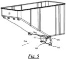
- Bin 26 includes a chute 646 at the bottom for discharge of particulate food product 20.
- Bin 26 further includes a rotatable gate 648 configured to pivot from a normally closed position to an open position. In the closed position ( Figs. 4 , 5 ), gate 648 covers the bottom opening of chute 646, preventing discharge of particulate food product 20. In the open position ( Fig. 3 ), gate 648 is pivoted away from the bottom opening of chute 646 towards the front of the chute, thus allowing for product discharge.
- chute 646 is inserted into chute inlet 632. During insertion of chute 646 the top of arm 640 engages a flap 650, causing the front rotation of gate 648.
- bin 26 may be removed from transport section 28 for cleaning and/or change-over of product.
- flap 650 rotates (either by gravity or spring assisted), thus pivoting gate 648 back to the closed position.
- Chute 646 further includes an opposing pair of stops 652 positioned on the sides of the chute. Stops 652 define a limit of movement of gate 648 in the closed position.
- gate 648 acts to minimize or substantially eliminate leakage of product from the bottom opening of chute 646 during removal of bin 26.
- cutout portion 656 (aka over-center cutout) is disposed in the flights of transport device 32. As exemplified in Fig. 6B , cutout portion 656 is disposed in transport device 32 in an over-center position. Cutout portion 656 is formed as a notch having two perpendicular sides of unequal length. Cutout portion 656 is aligned below the opening of chute inlet 632. Those of skill in the art will appreciate that the dimensions of cutout portion 656 are sized commensurate with a target product (e.g. almond, or peanut). In merely exemplary nonlimiting examples, dimensions of 7.637 mm and 16.665 mm are used.
- a target product e.g. almond, or peanut
- the rear portion of front housing 628 includes a plurality of radially equally spaced-apart flutes 658 disposed around transport device 32.
- Flutes 658 are longitudinal recesses along a portion of the interior surface of sleeve 626, configured in number and size to maximize product flow from sleeve 626 forward toward milling device 618.
- the bottom three flutes 658 extend rearwardly along the interior surface of sleeve 626 below chute inlet 632 (see also Fig. 6A ).
- the number and size of flutes can be varied to adjust flow. In one example ( Fig. 7 ), five flutes, each being approximately 8mm in diameter, half depth, are utilized. In another example, 4 flutes are used which results in a lower flow rate and lower current draw on the motor.
- a pair of opposing texture adjustment screws 660 accessible through annular perimeter 638 allow adjustment of viscous food paste texture from coarse to fine. For nut products, the adjustments result in crunchy or creamy nut butter.
- Texture adjustment screws 660 are inserted through openings in annular perimeter 638 and are secured in corresponding helical slots within rear fixed grinder 621. Adjustment is made by loosening texture adjustment screws 660 and rotating the rear fixed grinder 621, relative to the longitudinal axis of transport device 32, into the desired position closer or further away from front rotating grinder 619, then re-tightening the texture adjustment screws. Preferably, the adjustment does not require the use of special tools, and the screws can be manually rotated.
- the top end of texture adjustment screws 660 may be any suitable type of thumb screw, such as including a knurled surface to allow ease of manual operation.
- manual fasteners may be used for assembly and disassembly of transport section 28, transport device 32, and outlet adapter 610 from power source 30. Assembly and disassembly without special tools acts to reduce device-cleaning time and product change-over time, and reduces the potential for loss of special tools.
- power source 30 is protected by an enclosure 662.
- a backer plate 664 is secured to enclosure 662 via thumb screws 666.
- a ring 668 is placed in an opening in backer plate 664, and a shaft 670 of a motor 672 (see motor in Fig. 12 ) extends forward through the opening.
- transport device 32 The rear end of transport device 32 is secured to shaft 670 via screw set 674.
- transport section 28 is inserted onto transport device 32 and rear plate 630 is secured to backer plate 664 via knobs 676.
- the transport device is secured to the transport section via fastener set 678.
- the rear fixed grinder is secured to front housing 628 via texture adjustment screws 660, as described above.
- Front rotating grinder 619 is inserted onto the front of transport device 32, and outlet adapter 610 is secured to front housing 628 via post 642 and clamp bar 636 as described above.
- the front rotating grinder is operably coupled to power source 30.
- power source 30 further includes a variable frequency drive (VFD) controller 680 operatively connected to motor 672.
- VFD controller 680 is in electrical communication with motor 672 and operator interfaces, which include an on/off switch 684 (shown in Fig. 10 ) and a time adjustment feature 686 (shown in Fig. 13 ).
- VFD controller 680 enables motor 672 to operate using various world-wide input voltages and frequencies, and maintains improved torque and horsepower. Further, VFD controller 680 includes overload protection with single push button recovery and PLC controllability to provide specific user-selectable and customizable torque/speed profiles via computer program profiles.
- a 60Hz, 110 Volt, 3 phase, VFD controlled, 1.5hp motor is used. This arrangement allows high torque from a relatively smaller motor. Conventional systems utilize single phase motors that are necessarily larger.
- a 230V, 50Hz system is provided. The following input power options are preferred: 110V / 60Hz, 220V / 60Hz, and 230V / 50Hz.
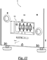
- a group of toggle switches in the rear side of enclosure 662 facilitates a time adjustment feature 686.
- the switches are operatively connected to VFD controller 680.
- Time adjustment feature 686 allows selection from a plurality of pre-determined run times for motor 672.
- the pre-determined run times may be selected from a range of 15 seconds to 180 seconds.
- Time adjustment feature 686 is a "user-friendly" feature that takes the guess work out of adjusting unit run time. For example, it may include a series of four toggle switches, the first switch corresponding to 15 seconds, the second corresponding to 70 seconds, the third corresponding to 125 seconds and the fourth corresponding to 180 seconds run time.
- Outlet adapters 100/410 for a viscous food product grinding and dispensing system 412 are shown in Figs. 15 and 16 according to various embodiments of the present invention.
- Outlet adapters 100/410 include a discharge cover 114/414 and a flexible nozzle 16/116.
- Discharge covers 114/414 are configured to house a milling device 418 (similar to milling device 618) and to receive flexible nozzle 16/116.
- System 412 includes a bin 26 for storage of particulate food product 20, gravity fed transport section 28 that receives the particulate food product and a power source 30 that drives a transport device 432 as well as milling device 418.
- Transport device 432 is located within transport section 28 and operates to move particulate food product 20 downstream to milling device 418.
- milling device 418 receives a supply flow of particulate food product 20 and processes the particulate food product into a pressurized supply flow of viscous food paste 22 for dispensing through nozzle 16/116 as an elongated stream
- discharge cover 414 being similar to discharge cover 614, has a generally cylindrical shape and includes an annular sidewall 415. Discharge cover 414 also includes a spout 417 configured to act as an environmental guard and tamper deterrent for surrounded flexible nozzle 16.
- the interior of discharge cover 414 may be curved to align adjacent the outer curved surface of milling device 418.
- Milling device 418 includes a front rotating grinder 419 and a rear fixed grinder 421.
- Outlet adapter 410 also includes a gasket 422 fastened to the rear of discharge cover 414 via fasteners 426.
- Gasket 422 provides improved sealing of discharge cover 414 against rear fixed grinder 421.
- discharge cover 414 with gasket 422 is aligned against a front housing 428, (may be secured by clamp bar 636, similar to discharge cover 614), and then post 440 is fastened to front housing 428 through receptor 444.
- Post 440 and fasteners 426 are configured to allow for installation both manually and by use of tools.
- transport device 432 is similar to transport device 32, except for including a hollow bore portion 454, and having two opposing cutouts 456 disposed at approximately 180 degrees out of phase, relative to each other. Cutouts 456 are aligned below the opening of a chute inlet 434.
- transport device 432 is solid, and does not include hollow bore portion 454.
- transport device 432 is formed with an outer diameter of about 35.5 mm, and cutouts 456 are formed with a depth of about 7.637 mm and a width of about 16.665 mm.
- spout 417 extends from the bottom of annular sidewall 415, and encloses all of flexible nozzle 16, except the bottom outlet. Spout 417 may be integral or ancillary to outlet adapter 410.
- nozzle 16 includes a proximal end 34, a distal end 36.
- a valve 38 with a hollow interior passage 40 is formed in the nozzle.
- Nozzle 16 is coupled at the proximal end 34 to an aperture 442 in annular sidewall 415 of discharge cover 414.
- Nozzle 16 includes a mounting flange 44 at the proximal end 34 configured to fit against the concave curved interior surface of discharge cover 414. As seen in Fig.
- discharge cover 414 may include a shoulder 446 configured to abut the outer edges 48 of mounting flange 44.
- a perimeter edge 49 of flange 44 may include radius curved portions configured to seal against concave curved interior edge portions of discharge cover 414.
- Valve 38 is biased in a normally closed position and flexes to an open position due to a pressure exerted by the discharge of viscous food paste 22 as it is forced downstream through interior passage 40, and returns to the normally closed position upon flow cessation.
- Valve 38 is configured with interior geometry features that pinch or chop against elongated stream 24 as the valve returns to the closed position, effectively slicing through, pinching, or breaking apart the elongated stream. Pinching elongated stream 24 within valve 38 reduces the amount of paste residue attached to the external face of the bottom of the valve after the valve returns to the closed position.
- the properties of viscous food paste 22 allow for an alternative flexible nozzle to be utilized.
- Such flexible nozzle has a discharge opening that also enlarges, or deforms, due to product stream pressurization, and returns to the closed position upon flow cessation.
- the severing of elongated stream 24 leaves substantially no paste residue attached to the external face of the bottom of the valve after the stream flow is de-pressurized.
- the properties of viscous food paste 22 allow for an alternative rigid or semi-rigid nozzle to be utilized. Such properties of viscous food paste 22 inherently result in a clean drop or severing of elongated stream 24 due to forces of gravity once the supply flow is depressurized. Such natural severing of elongated stream 24 leaves substantially no paste residue attached to the external face of the bottom of the valve after the stream flow is de-pressurized. In some embodiments, such clean dropping viscous food paste 22 may be dispensed with just the discharge cover in place, without any nozzle inserted. In some embodiments, the discharge cover does not utilize spout 417, and a separate, plastic sneeze guard (not shown) is supported in front of the discharge of valve 38.
- a suitable biasing device such as a pinch roller set (not shown) is used to assist flexible nozzle 16 in returning to its original, closed position after the stream flow is de-pressurized.
- a pinch roller set is activated adjacent to proximal end 34 of valve 38.
- the rollers of the pinch roller set are urged closer together to slightly compress valve 38 as the rollers are moved downwardly towards the distal end 36.
- valve 38 returns to the closed position, elongated stream 24 is severed, and leaves substantially no paste residue attached to the external face of the bottom of the valve.
- the pinch roller set is thereafter returned to a starting position.
- the operation of the pinch rollers can be achieved by various methods, including full or partial automation.
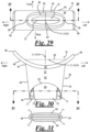
- mounting flange 44 includes an opening 50 at proximal end 34 of interior passage 40. Opening 50 has an ovoid shape and is configured to receive viscous food paste 22. Interior passage 40 tapers asymmetrically in two dimensions (see FIGS. 30 , 33-35 ) slightly from opening 50 downstream toward distal end 36.
- Valve 38 includes a pair of opposing flap walls 52 joined by a pair of opposing side walls 54, the flap walls and side walls together forming continuous interior passage 40.
- valve 38 has a side exterior linear dimension length "L” and a bottom exterior linear dimension width "W".
- L and W are from about 1.65 inches to about 2.2 inches, and preferably “L” is about 2.0 inches and "W” is about 1.65 inches.
- valve 38 has an exterior linear dimension depth "D" of about 0.75 inches to about 1.25 inches, and preferably about 0.85 inches.
- a reference planar oval 56 is visualized as located above opening 50, in the X-Y plane; the reference planar oval having a central X axis, Y axis and perpendicular Z axis.
- Opening 50 has a generally concave curvature about the Y axis configured to match the curvature of annular sidewall 415 of discharge cover 414.
- the interior transition from flange 44 to side walls 54 and flap walls 52 is formed in a radius curvature.
- the transition from flange 44 to side walls 54 has a generally convex curvature 58 relative to the Z axis and the transition from the flange to flap walls 52 has a generally convex curvature 60 relative to the Z axis.
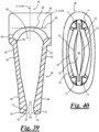
- Valve 38 is biased in a normally closed position (see Fig. 38 ) and flexes to an open position (see Fig. 39 ) due to a pressure exerted by the discharge of viscous food paste 22.
- Valve 38 has a generally duckbill shape, and includes a sheath portion 62 and a flexible portion 64.
- Sheath portion 62 is located on side walls 54 and on the upper portion of flap walls 52.
- flexible portion 64 forms a curved interface 65 with sheath portion 62.
- Sheath portion 62 is configured with a lesser interior taper angle 66 from about 7 degrees to about 8 degrees relative to the Z axis.
- Flexible portion 64 is located on flap walls 52 and is configured with a greater interior taper angle 68.
- the wall thickness of flexible portion 64 increases as it tapers towards port 70.
- the greater interior taper angle 68 is about 18 degrees and a greater exterior taper angle 69 is from about 11 degrees to about 14 degrees, relative to the Z axis.
- Flexible portion 64 is configured to be biased in a normally closed position and flexes outward slightly toward the exterior as the pressurized supply flow of viscous food paste 22 is forced downstream through interior passage 40 (see Fig. 39 ).
- Interior passage 40 is defined by opening 50 and the proximal ends 34 of flap walls 52, having a generally ovoid cross-section about the Z axis, that gradually decreases in cross sectional area downwardly (along the Z axis) towards a normally closed port 70 of flexible nozzle 16 at distal end 36.
- Port 70 is configured for operation from the biased normally closed position to the open position for discharge of viscous food paste 22 in the elongated stream 24.
- Elongated stream 24 may be captured by the user within a container below port 70 (see Fig. 15 ).
- Port 70 is configured such that the force from the pressurized supply flow of viscous food paste 22 urges the port open and once the supply flow is depressurized and the force ceases, the removal of the force causes the port to return to the normally closed position ( Fig. 38 ). Port 70 will move to the open position when the product processing pressure of the supply flow of viscous food paste 22 reaches a predetermined valve threshold pressure, and will return to the closed position when the product processing pressure falls below the valve threshold pressure.
- Each flexible portion 64 includes opposing pairs of tapered stiffening portions 71 adjacent to side walls 54. At each side wall 54 adjacent stiffening portions 71 taken together are configured to be from about two-thirds to about one-half of the width of port 70 at distal end 36, and are configured to assist in biasing the port into the closed position.
- Port 70 includes a pair of opposing gates 72 at the distal end 36 of the interior surfaces of flap walls 52.
- gates 72 In the closed position, gates 72 have the appearance of a substantially closed elongated slit.
- the middle portion thereof opens relatively more than the end portions to form a bulbous middle portion 75.
- gates 72 each deform in a generally bell-like, somewhat concave curvature, to form an ovaloid shaped middle portion 75 of outlet 74 (see Fig. 40 ).
- Valve 38 of nozzle 16 is configured to reduce the amount of paste residue attached to external face 76 by effectively severing the elongated stream 24 without causing excessive pressure drop when the valve is in the open position.
- gates 72 are configured to be angled slightly relative to each other along the X axis from a pinch point 78 down towards a gap at outlet 74, and thus are biased to abut close together at the pinch point when port 70 is in the normally closed position.
- gates 72 of port 70 are configured to pinch or chop against elongated stream 24 as the port returns to the closed position, effectively slicing through or breaking apart the elongated stream.
- the severed elongated stream 24 falls into the user's container below, thereby reducing the amount of residue viscous food paste 22 remaining attached to external face 76 of port 70.
- an outlet adapter 100 includes a discharge cover 114 and a flexible nozzle 116.
- Nozzle 116 has many similar features to nozzle 16 described above (see Figs. 27-40 ).
- Nozzle 116 is coupled at the proximal end 34 to an aperture 42 in annular sidewall 115 of discharge cover 114.
- Nozzle 116 includes a valve 138 and a mounting flange 144 at the proximal end 34 configured to fit against the concave curved interior surface of discharge cover 114.
- Discharge cover 114 may include a shoulder 146 configured to abut the outer edges 148 of mounting flange 144.
- mounting flange 144 includes an opening 150 at proximal end 34 of an interior passage 140 configured to receive viscous food paste 22.
- Valve 138 is biased in a normally closed position (see Fig. 48 ) and flexes to an open position (see Fig. 49 ) due to a pressure exerted by the discharge of viscous food paste 22.
- Valve 138 has a generally duckbill shape, and includes sheath portion 62 and a flexible portion 164. On flap walls 52, flexible portion 164 forms a curved interface 165 with sheath portion 62.
- Interior passage 140 is defined by opening 150 and the proximal ends 34 of flap walls 52, having a generally ovoid cross-section about the Z axis, that gradually decreases in cross sectional area downwardly (along the Z axis) towards a normally closed port 170 of flexible nozzle 116 at distal end 36.
- Port 170 is configured for operation from the biased normally closed position to the open position for discharge of viscous food paste 22 in the elongated stream 24.
- Port 170 includes a pair of opposing gates 172 at the distal end 36 of the interior surfaces of flap walls 52.
- gates 172 In the closed position, gates 172 have the appearance of a closed slit.
- gates 172 As gates 172 are forced open by the pressurized supply flow of viscous food paste 22 to form an outlet 174.
- the middle portion thereof opens relatively more than the end portions to form a bulbous middle portion 175.
- gates 172 each deform in a generally bell-like, somewhat concave curvature, to form an ovaloid shaped middle portion 175 of outlet 174 (see Fig. 50 ).
- Gates 172 are configured to be substantially parallel, and are further configured to be biased to abut together when port 170 is in the normally closed position. As such, gates 172 of port 170 are configured to pinch or chop against elongated stream 24 as the port returns to the closed position, effectively slicing through or breaking apart the elongated stream. The severed elongated stream 24 falls into the user's container below, thereby reducing the amount of residue viscous food paste 22 remaining attached to an external face 176 of port 170.
- Nozzles 16, 116 are made of a suitable flexible, elastomeric material, such as rubber, for example.
- the rubber is a food grade suitable for use with various particulate food products 20.
- the nozzle material may be configured of a durometer hardness to match the type of product used for milling, and the type of viscous food paste 22 produced by the viscous food product grinding and dispensing system 12. The durometer hardness utilized is coordinated to allow the valves 38, 138 to deform and open when interior passages 40, 140 are pressurized above a predetermined level and to seal closed causing a reduced residue drip when depressurized.
- the durometer of the rubber used for the nozzle may be from about Shore 60A to about Shore 90A.
- the durometer may vary depending on the size of the nuts used, and the texture of nut butter desired (chunky, coarse or smooth).
- the desired dispense rate of elongated stream 24 is also taken into account with the selection of rubber durometer.
- larger sized peanuts produced a rate of about 1.3 lbs/minute to about 1.4 lbs/minute.
- smaller sized peanuts produced a rate of about 3.1 lbs/minute to about 3.6 lbs/minute.
- flexible nozzle 116 is preferably made from Shore 80A rubber for use in peanut butter applications to produce a flow rate of about 1.5 to about 3.4 lbs/minute of peanut food paste.
- the Shore 80A flexible nozzle 116 produces a dispense rate from about 3.2 to 3.4 lbs/minute with smaller sized peanuts and from about 1.5 to 1.7 lbs/minute with larger sized peanuts.
- Discharge covers 114, 414, 614 may be made from a suitable food grade metal, such as stainless steel for example. Flexible nozzles 16, 116 are easily inserted and removed for cleaning from aperture 42 in discharge covers 114, 414, 614. Various parts shown are interchangeable in different system embodiments. For example, transport device 432 may be used within front housing 628.
- valves 38, 138 may be used in other applications, such as inline in industrial food processing.
- Valves 38, 138 may be mounted inline in a square, cylindrical or rounded conduit, where the corresponding flange perimeter is square, circular, or rounded and configured to mate with the adjacent conduit structure.
- the viscous food product dispensed by valves 38, 138 may be any suitable food product, such as dough, jam or mayonnaise.
- the valves may also be utilized with other suitable viscous products such as caulk, adhesives or petroleum jelly.
- a viscous food product dispensing system comprises a transport section 28 having a chute inlet 632 for receiving a particulate food product, and a transport device 32 adapted to process and longitudinally convey the received particulate food product.
- "adapted to" means that transport device 32 is designed and constructed to include an auger-like function so as to convey the food product longitudinally.
- such conveyance is from the transport section 28 into outlet adapter 610.
- food product is conveyed longitudinally from the transport section into outlet adapter 610 through one or more flutes 658.
- the transport device 32 has an over-center cutout 656 operatively aligned with the chute inlet 632. As depicted in Figs. 60A & 60B, over-center cutout 656 is disposed along a portion of transport device 32. As depicted in Fig. 6D , over-center cutout 656, as viewed in cross section, extends over, or past, the centerline 33 of transport device 32.
- over-center cutout 656 is operatively aligned with chute inlet 632 so that food product (e.g. nuts) enter chute inlet 632 and are thereafter engaged by cutout 656, and processed (e.g. crushed), as transport device 32 longitudinally conveys the processed food product.
- food product e.g. nuts
- cutout 656 e.g. crushed
- transport device 32 is operatively engaged with one or more flutes 658.
- Fig. 51 depicts a cross-sectional view showing transport device 32 disposed between sleeve inner wall 627 of sleeve 626 and opposing sleeve inner wall 629 of sleeve 626.
- sleeve inner wall 627 of sleeve 626 and opposing sleeve inner wall 629 of sleeve 626 are substantially vertical and each transition to a tapered upper portion 631, 633.
- the sleeve 626 is configured with an inner sleeve wall 627.
- the inner sleeve wall 627 is spaced apart from the transport device 32 in a region about the over-center cutouts 656.
- the inventors have recognized that while in previous dispensers the tapered upper portions 631, 633 of the sleeve 626 helped to direct food product towards the transport device 32, it has been discovered that despite the previously disclosed advantages of the over-center cutouts 656, that larger whole nuts, including, but not limited to pistachios and almonds require a processing zone 708 adjacent the transport device 32 within which they can be trapped and broken by the transport device 32.
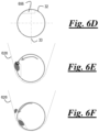
- the transport device 32 exemplarily rotates in the direction of arrow 707, this rotation draws the whole nuts into the processing zone 708 which may include a portion of the associated flute 658.
- the inner sleeve wall 627 is located exterior of the associated flute 658 in a direction from the transport device 32. That is, the inner sleeve wall 627 is further from a center-line of the transport device 32 than the associated flue 658.
- the whole nuts are broken between a processing surface 802 formed in the inner sleeve wall 627 in the processing zone 708 and the flights 712 of the transport device 32 at the over-center cutouts 656. Further aspects of this are depicted in Figs. 52-59 .
- Figure 52 is a perspective view of the transport section 28.
- Figure 53 is a top view of the transport section 28 of Fig. 52 .
- Fig. 51 is a cross-sectional view taken along line 51-51 of Fig. 53 .
- Figs. 54 and 55 are other cross-sectional views of the transport section 28 as noted in Fig. 53 . Comparing Figs. 51 , 54 , and 55 . It can be seen that a portion of the flutes are formed into the lower portion 709 of the sleeve 626 adjacent to the transport device 32. As seen from comparison of Fig. 55 to Fig. 51 , as well as in Figs. 52 and 53 , the lower portion 709 includes a taper 711 from a back end 713 of the lower portion 709 towards an outlet aperture 710 through which the flutes 658 and the transport device 32 extend.
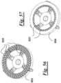
- Figure 56 depicts an example of a first grinding plate 653 and Figure 57 depicts an example of a second grinding plate 654.
- transport device 32 is adapted to convey the received particulate food product from the transport section 28 into an outlet adapter 610.
- the outlet adapter 610 includes a discharge cover 614 that encloses a milling device 618.
- the milling device 618 includes grinding plates 653, 654 each of the grinding plates 653, 654 include one or more grinding teeth 620. It is to be understood that the term “milling device” is interchangeable with “grinding device” as used herein.
- the milling device is adapted to further process the particulate food product into a viscous food paste.
- "adapted to” means that milling device 618 converts the received food product into a viscous food paste by grinding the food product between grinding plates. In one aspect, the conversion is achieved by cooperating grinding plates, one being stationary and the other being rotatable so as to grind the food product.
- the grinding plates 653, 654 rotate, relative to each other, to process (grind) a food product.
- relative rotation can be achieved in various ways.
- grinding plate 653 is stationary and grinding plate 654 is rotatable relative to the grinding plate 653. In another aspect, this may be reversed. In yet another aspect, both plates rotate, relative to each other, at varying speeds and directions.
- the consistency and/or viscosity of the food product can be adjusted by varying the amount of energy transferred to the food product.
- One such method of accomplishing this is to vary the number and arrangement of grinding teeth on the various grinding plates.
- the size, location, and relative size of grinding teeth 620 are adjusted according to multiple variables (aka commensurate with a food product).
- the grinding plates (as described herein) can be tuned to nuts of various sizes so as to effect the viscosity and/or consistency of nut butter.
- the amount of work done can be tuned to meet the needs of the product for desired end product consistency. This may be useful, for example, in order to adjust the grinding plates 653, 654 to accommodate variations in the quality of the particulate food product.
- a method for adjusting the consistency and/or viscosity of a food product comprises the steps of: obtaining a viscous food product dispensing system comprising: a transport section 28 having a chute inlet 632 for receiving a particulate food product, a transport device 32 being adapted to convey the received particulate food product from the transport section 28 into an outlet adapter 610, the outlet adapter 610 comprising a discharge cover 614 enclosing a milling device 618, the milling device 618 comprising front and rear grinding plates 619, 621, each of said front and rear grinding plates having one or more grinding teeth 620; and varying the location and/or number of the one or more grinding teeth according to multiple variables of a food product.
- two or more of the grinding teeth are arranged circumferentially around either or both of the front or rear grinding plates.
- the grinding teeth 620 of either or both of the grinding plates 653, 654 are arranged in three or more groups of circumferentially oriented teeth, the groups being concentrically arranged, and disposed radially outside of four or more linear rows of teeth, each row having two or more teeth aligned radially outwardly from a center of the respective grinding plate, the four or more rows being circumferentially spaced apart.
- the grinding teeth of either or both of the grinding plates 635, 654 are arranged in one or more groups of circumferentially oriented teeth 620 being disposed radially outside of one or more linear rows of teeth, each row having two or more teeth aligned radially outwardly from a center of the respective grinding plate, and if more than one row, the rows being circumferentially spaced apart.
- a first grinding plate 653 in one aspect has three groups of circumferentially oriented teeth 620, the groups being concentrically arranged, and disposed radially outside of four linear rows of teeth, each row having two teeth aligned radially outwardly from a center of the respective grinding plate, the four rows being circumferentially spaced apart.
- a second grinding plate 654 in one aspect has one group of circumferentially oriented teeth 620 being disposed radially outside of four linear rows of teeth, each row having two teeth aligned radially outwardly from a center of the respective grinding plate, the four rows being circumferentially spaced apart.
- first and second grinding plates 653, 654 are interchangeable with front and rear grinding plates 619, 621 & 419, 421 and that grinding teeth 620 are intended for use in all of the foregoing, in the various aspects of the subject technology as described herein. Grinding plate 654 is designed to tune the amount of work introduced to the product to yield desired viscosity of end product.
- front grinding plate 619 is threadedly connected to proximal end 687 of transport device 32, such that the front grinding plate is removed from the transport device in a removal direction.
- the threaded connection of front grinding plate 619 to proximal end 687 of transport device 32 comprises a direct connection whereas in other aspects an intermediate connector can be used to accomplish the same functionality.
- the subject technology can be configured such that the "removal direction" can be either clockwise or counterclockwise.
- transport device 32 and front grinding plate 619 rotate in a counterclockwise direction to grind food product, and the threaded connection between front grinding plate 619 and transport device 32 is such that the removal direction is also counterclockwise; i.e. front grinding plate 619 is tightened in a clockwise direction.
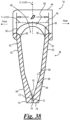
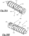
- Figs. 58A and 58B depict left and right perspective views of an example of a transport device 32, including the flights 712 and the over-center cutout 656.
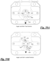
- distal end 688 of transport device 32 has a receptacle 689 for operatively engaging a lock pin 690.
- the distal end 688 of transport device 32 may be relatively smooth (exclusive of receptacle 689) and does not include structure to realize auger functionality.
- Receptacle 689 is adapted to restrain (aka in a locked position) transport device 32 from rotating in the removal direction when lock pin 690 is inserted within the receptacle 689 (e.g. Fig.
- the receptacle 689 is adapted to allow the transport device 32 to rotate in a counter-removal direction when the lock pin 690 is inserted within the receptacle 689. It should be noted that the insertion of lock pin 690 into receptacle 689 can be manual (e.g. a user engagement), or automatic (e.g. in response to a predetermined event, or series of events).
- receptacle 689 is adapted to eject the lock pin 690 when the transport device 32 is rotated in the counter-removal direction.
- receptacle 689 has a lower surface 691 adjacent to a restraining wall 692. Lock pin 690 engages restraining wall 692 when lock pin 690 is inserted within the receptacle 689 and the transport device 32 is rotated in the removal direction, and lower surface 691 ejects lock pin 690 when the transport device 32 is rotated in the counter-removal direction.
- distal end 688 of transport device 32 has a second receptacle 693 for operatively engaging a lock pin 690.
- the second receptacle 693 is disposed one hundred and eighty degrees relative to the first receptacle 689, but is otherwise substantially identically shaped. It should be noted that, in the configuration depicted in Fig. 64B, only one lock pin 690 is used and thus will only engage one of the two receptacles 689 or 693.
- front grinding plate 619 rotates in counterclockwise direction to grind a food product.
- the threaded connection between the auger (aka transport device 32) and grinding plate is such that the plate is unscrewed in a counterclockwise direction, so that the plate is not unscrewed during operation, i.e. when the auger rotates in counterclockwise direction, the force is in a direction that would cause the plate to be tightened.
- lock pin 690 aka “locking pin”, “anti-rotation pin” is moved into a locked position and engaged (manually in one aspect) into receptacle 689. As shown in Figs.
- a viscous food product dispensing system in one aspect includes a transport section 28 having a chute inlet 632 for receiving a particulate food product.
- a transport device 32 moves the received particulate food product from the transport section into an outlet adapter 610.
- the outlet adapter 610 includes a discharge cover 614 enclosing a milling device 618.
- the milling device being adapted to process the particulate food product into a pressurized flow of viscous food paste that is discharged through a nozzle 16, the nozzle being disposed through the discharge cover 614.
- the nozzle 16 is partially covered by a spout 417.
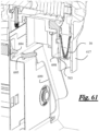
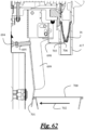
- a proximal end 704 of an actuating lever 699 is operatively connected to the transport section, the actuating lever 699 is movable between engaged and disengaged positions.
- a medial portion 705 of the actuating lever 699 is adapted to activate (e.g. turn on, engage) a push button 694 when the actuating lever 699 is in the engaged position.
- a chopping bracket 698 is operatively connected to the medial portion 705 of the actuating lever 699, and a distal end 706 of the chopping bracket 698 protrudes through a slot 703 disposed in the spout 417. In the disengaged position, the distal end 706 of the chopping bracket 698 cuts off the pressurized flow of viscous food paste that is discharged through the nozzle 16. An important aspect is thereby achieved because undesirable "dangle" of food product that would otherwise remain upon cessation of flow, is prevented.
- the chopping bracket 698 is pivotably connected to the medial portion 705 of the actuating lever 699 by one or more pull out pins 697 so that the distal end 706 of the chopping bracket 698 protrudes through a slot 703 in a reciprocating manner as the actuating lever 699 is moved between engaged and disengaged positions.
- Those of skill in the art will appreciate that various linkages and brackets can be used to achieve this functionality.
- proximal end 704 of the actuating lever 699 is pivotably connected to the transport section 28.
- proximal end 704 of the actuating lever 699 is connected to an actuator base frame 696, and the actuator base frame 696 is pivotably connected to the transport section.
- the operative connection as herein described is intended to allow actuating lever 699 to cause the distal end 706 of the chopping bracket 698 to cut off the pressurized flow of viscous food paste that is discharged through the nozzle 16, and additionally in one aspect, to activate push button 694 as the actuating lever 699 moves between engaged and disengaged positions.
- a push button actuating pin 695 is disposed proximate the medial portion 705 of the actuating lever 699 so as to operatively engage and activate the push button 694 when the actuating lever 699 is in the engaged position.
- a cup 700 is forcibly held under the nozzle 16 so as to move the distal end 701 of the actuating lever 699 (typically biased in the disengaged position) in the direction of arrow 702 (Fig. 67), which causes the actuating lever 699 to be moved to the engaged position.
- the distal end 706 of the chopping bracket 698 is positioned to allow flow through nozzle 16, and push button 694 is activated thereby causing the flow of food product from the nozzle 16.
- the actuating lever 699 Upon removal of the cup 700, the actuating lever 699 is moved to the disengaged position and the distal end 706 of the chopping bracket 698 is moved so as to cut off the pressurized flow of viscous food paste that is discharged through the nozzle 16, thereby pinching off, or severing the product flow.
- Some embodiments can include a combination of features that work in unison to provide an adaptable viscous food dispensing system that may be used with a variety of different food products.
- a transport section with a sleeve having an asymmetrical cross section (see, for example, Fig. 51 ) with an outlet adaptor that can use grinding plates with different grinding tooth configurations
- a viscous food dispensing system can be used to process and grind whole nuts into a viscous food product with a high or low viscosity.
- a viscous food dispensing system 12 can be configured to process particulate food product that is captured in a processing zone 708 between the transport device 32 and a processing surface 802.
- the processing surface 802 can extend downward from the tapered upper portion 631 of the chute inlet 632 towards the curved lower portion 709 of the sleeve 626, and may run longitudinally along at least a portion of the length of the sleeve 626 and the transport device 32.
- the processing surface 802 is formed in the inner sleeve wall 627 so that the width of the processing zone 708 is larger than the distance between the transport device 32 and the side wall 629 of the sleeve 626 opposite the processing surface 802.
- the large width of the processing zone 708 may be useful, for example, in order to capture and process whole nuts (e.g., almonds).
- whole nuts e.g., almonds.
- the transport device 32 rotates in a counterclockwise direction, the particulate food product within the processing zone 708 can be captured between the flights 712 and a leading edge 804 of the over-center cutout 656 and the processing surface 802, causing the captured particulate food product to be broken up into smaller pieces. Those smaller pieces can then be conveyed from the sleeve 626 to the outlet adaptor 610 for grinding.
- a transport device 32 that includes a pin receptacle 689 and a lock pin 690 that is slidably revived in the sleeve 626 (see, for example, Figs. 63A-64B) can be useful, for example, to allow a user to remove and attach various different grinding plates to the transport device 32 without the use of specialized tools. This may allow a user of the system 12 to quickly adjust for different types of particulate food product, or to increase or decrease the viscosity of the viscous food product produced by the system 12.
- a single viscous food dispensing system 12 can be used with a wide variety of different particulate food products, both large and small, to produce viscous food products having a variety of different consistencies and viscosities.
Landscapes
- Engineering & Computer Science (AREA)
- Food Science & Technology (AREA)
- Life Sciences & Earth Sciences (AREA)
- Chemical & Material Sciences (AREA)
- Polymers & Plastics (AREA)
- Mechanical Engineering (AREA)
- Crushing And Pulverization Processes (AREA)
- Filling Or Emptying Of Bunkers, Hoppers, And Tanks (AREA)
- Confectionery (AREA)
Description
- The present disclosure relates generally to viscous food product grinding and dispensing systems, and in particular to features for such systems configured to improve performance of the production of viscous food paste.
- Grinding dispensers for dispensing bulk food products are used to dispense a wide variety of ground materials, which may include, for example, nuts, coffee, and grain. Generally, such systems include a hollow hopper-type bin having an inlet at an upper end utilized to fill the enclosure with bulk product, a transport section that receives the food product by gravity, a manual or electric motor power source that mechanically drives a transport device and a milling device, and a discharge cover for the milling device. In one aspect the transport device may be a rotatable auger that is coupled to the power source. The discharge cover includes one or more outlet openings utilized to dispense the material into a container for the user.
- Existing grinding dispenser systems provide nut butter freshly ground from various types of nuts, such as peanuts and almonds. In operation of such nut grinding dispensers, a pre-processed nut product is further ground to produce nut butter, which is forced as a viscous paste to the bottom of the discharge cover and dispensed from the outlet opening as an exposed viscous paste stream.
- Conventional systems produce an exposed paste stream that is problematic for sanitary reasons. The present invention overcomes this disadvantage by covering dispense residual paste (commonly referred to as "dangle") with a spout (aka shroud). After the grinding dispenser has been deactivated, conventional systems further produce an exposed residue drip attached to the exterior of the product outlet.
US2017/267441 discloses a viscous food product dispensing system having a transport section for receiving a particulate food product from a bin, an auger for processing and conveying the received particulate food product from the transport section into an outlet adapter via one or more flutes, a milling device housed in the outlet adapter, and a discharge nozzle in the outlet adapter that pinches off the viscous food product created by the milling device.
US5553792 discloses a sampling mill for grinding discrete materials to obtain a representative sample in which the material to be sampled is fed to a rotary worm gear of substantial length connected to a burr plate to feed the material between a second plate.
US3666186 discloses a thin film mill for simultaneous reduction in size as by separation of agglomerates of particle clusters and dispersion of the fine particles in a liquid carrier, constructed of a plurality of rotatable cylindrical sections arranged in a row, each section having a helical groove cut in its cylindrical surface, the grooves being variable in depth becoming shallower and wider with progressively increasing pitch from inlet to outlet, the sections being mounted for application eccentrically of radial pressure upon a thin film of the dispersion between each section and the walls of the confining casing.
The present invention is defined by the appended claims. - Examples of the dispensers as disclosed herein provide improvements over the above-noted conventional systems and others. The disclosed dispensers may be especially suitable for larger nuts, by increasing the gap, or distance, between the transport device (auger) and housing wall (aka inner wall of transport section). The larger gap allows larger nuts to be captured.
- Other examples of the disclosed dispensers provide a nozzle at the product outlet having a generally flexible valve configured to automatically pinch off product residue drips. Thus, the nozzle valve prevents dripping of the product after dispensing has ceased. In some embodiments, the nozzle is covered by a spout to shield the food product outlet from environmental contamination and public tampering.
- Examples as disclosed in further detail herein may include a variable frequency driven (VFD), 3 phase motor, that provides higher torque with a volumetrically smaller motor. The high torque allows a more efficient grinding of product. The smaller motor allows a smaller overall footprint. Utilizing a VFD controller allows for motor operation using various world-wide input voltages and frequencies, maintains improved torque and horsepower, and can provide specific torque/speed profiles via computer program profiles.
- As disclosed in further detail herein, a safety system may operate to disable the electronic drive system upon detection of removal of either the hopper and/or front cladding (merchandizer). Still further examples may include a pivoting shutter (aka gate) on the hopper dispenser, a manually adjustable texture modification system fed by a unique flute arrangement, or a run time adjustment feature. The pivoting gate automatically closes off the product bin discharge chute as the bin is removed from the unit, reducing product loss. Texture adjustment screws provide easy manual adjustment, without the need for special tools, of a rear fixed grinder position, relative to a front rotating grinder, so as to adjust the coarseness, or product texture. Utilizing manual fasteners for the disassembly and reassembly of the grinding system shortens the clean time and product change-over time for the unit. The run time adjustment feature allows the unit owner to quickly select from a plurality of pre-determined run times for the motor.
- A transport section for a viscous food product grinding and dispensing system may include a transport device having an over-center cutout within a housing sleeve, the interior surface of the housing sleeve including radial flutes for regulating product flow from the sleeve to the milling device.
- An outlet adapter for a viscous food product dispensing system may include a discharge cover. The discharge cover may be configured to receive a pressurized supply flow of particulate food product and to house a milling device for processing the particulate food product into a pressurized supply flow of viscous food paste for dispensing. A flexible nozzle is coupled at a proximal end to the discharge cover. The flexible nozzle includes a valve configured to flex to an open position under force from the pressurized supply flow of viscous food paste and return to a closed position once the supply flow ceases. The valve includes an outlet being configured to pinch off and sever the viscous food paste as the valve returns to the closed position; whereby the severing of the viscous food paste by the outlet reduces the amount of viscous food paste remaining attached to an external face of the outlet.
- An outlet adapter may include a discharge cover and a flexible nozzle. The discharge cover is configured to receive a pressurized supply flow of particulate food product and to house a milling device for processing the particulate food product into a supply flow of viscous food paste for dispensing. The nozzle includes a proximal end, a distal end and a valve with a hollow interior passage. The nozzle is coupled at the proximal end to an aperture in the discharge cover. The hollow interior passage includes an opening at the proximal end configured to receive the viscous food paste. The hollow interior passage tapers downwardly towards a port at the distal end. The valve includes a flexible portion; the flexible portion is biased in a normally closed position and flexes to an open position under sufficient force for discharge of the viscous food paste. The flexible portion is configured such that force from the pressurized supply flow of the viscous food paste urges the port open and, once the supply flow stops, the port to returns to the closed position, thus pinching off or severing the viscous food paste.
- An example of a viscous food dispensing system includes a chute inlet configured to funnel whole food product into a sleeve. A transport device is configured to rotate within the sleeve. The transport device includes an over-center cutout. A processing surface extends downwards from the chute inlet towards a curved base of the sleeve along a portion of the transport device. The processing surface is spaced laterally apart from the transport device to define a processing zone between the processing surface and the transport device. Whole food product is broken into particulate food product as the whole food product is captured between a leading edge of the over-center cutout and the processing surface while the transport device is rotating. The transport device is configured to move the particulate food product away from the chute inlet.
- A method for tuning a viscous food dispensing system includes determining a desired viscosity of the viscous food product. The viscous food dispensing system may be configured to grind particulate food product into viscous food product between a stationary grinding plate and a movable grinding plate. The movable grinding plate configured to be rotated by a drive device. The method may further include uncoupling the movable grinding plate from the drive device to remove the movable grinding plate from the viscous food dispensing system. A replacement movable grinding plate may be selected based upon the desired viscosity of the viscous food product. The replacement movable grinding plate may be secured to the drive device to tune the viscous food dispensing system based on the desired viscosity.
- In an example, the stationary grinding plate, the movable grinding plate, and the replacement movable grinding plate each have a different number of grinding teeth. The grinding teeth may be arranged in one or more rings of grinding teeth on each grinding plate. In an example, the movable grinding plate and the replacement movable grinding plate each have a different number of grinding teeth. In an example, the movable grinding plate and the replacement movable grinding plate each have a different number of rings of grinding teeth.
- Further features of the inventive embodiments will become apparent to those skilled in the art to which the embodiments relate from reading the specification and claims with reference to the accompanying drawings, in which:
-
Fig. 1 is a schematic side view of a viscous food product grinding and dispensing system according to an embodiment of the present invention; -
Fig. 2 is a schematic flow diagram of the system ofFig. 1 ; -
Fig. 3 is a partial front perspective view of a viscous food product grinding and dispensing system according to an embodiment of the present invention, shown without the milling device; -
Fig. 4 is a front perspective view of the bin ofFig. 3 shown removed from the system; -
Fig. 5 is a rear perspective view of the bin ofFig. 4 ; -
Fig. 6A is a partial top plan view of the system ofFig. 3 shown with the bin, front rotating grinder and discharge cover removed; -
Fig. 6B is a front end view in section of a cutout in the auger/transport device, andFig. 6C , is the section ofFig. 6B shown rotated counterclockwise, also showing the interior surface of the adjacent sleeve; -
Fig. 6D is a front end view in section of a cutout in the auger/transport device (identical toFig. 6B ),Fig. 6E is the section ofFig. 6D shown rotated counterclockwise showing a captured nut, andFig. 6F is the section ofFig. 6E shown rotated further counterclockwise showing a partially crushed nut (it should be noted that the same effect can be achieved with a clockwise configuration); -
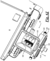
Fig. 6G is a front end view in section of a cutout in a prior art device,Fig. 6H is the section ofFig. 6G shown rotated counterclockwise showing an un-captured nut, andFig. 61 is the section ofFig. 6H shown rotated further counterclockwise, and showing an escaped nut; -
Fig. 6J is a top perspective view of the viscous food product grinding and dispensing system; -
Fig. 6K is an exploded side perspective view showing the transport section with transport device ofFig. 3 ; -
Fig. 7 is a front perspective view of the viscous food product grinding and dispensing system shown with the rear fixed grinder removed; -
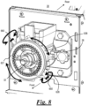
Fig. 8 is a front perspective view of the viscous food product grinding and dispensing system; -
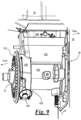
Fig. 9 is a side perspective view of the system ofFig. 3 shown with the front rotating grinder and discharge cover removed; -
Fig. 10 is an exploded view of the viscous food product grinding and dispensing system, shown with the bin removed; -
Fig. 11 is the exploded view ofFig. 10 shown without the power source and enclosure; -
Fig. 12 is a rear perspective view of the power source and enclosure ofFig. 10 shown with a rear portion of the enclosure removed; -
Fig. 13 is a partial rear perspective view of the power source enclosure ofFig. 10 ; -
Fig. 14 is a block diagram of the power source ofFig. 10 ; -
Fig. 15 is a schematic side view of an example of the viscous food product grinding and dispensing system; -
Fig. 16 is a schematic flow diagram of the system ofFig. 15 ; -
Fig. 17 is an exploded view of the transport section, outlet adapter, and milling device ofFig. 15 ; -
Fig. 18 is a partial top plan view of the assembled transport device inside the front housing ofFig. 17 ; -
Fig. 19 is a top plan view of the auger/transport device ofFig. 17 ; -
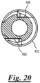
Fig. 20 is a rear view in section of the transport device ofFigs. 18 and 19 ; -
Fig. 21 is a rear perspective view of the outlet adapter ofFig. 17 with the nozzle assembled inside the discharge cover; -
Fig. 22 is a front perspective view of the outlet adapter ofFig. 21 ; -
Fig. 23 is a front view of the outlet adapter ofFig. 21 ; -
Fig. 24 is a short side view in section of the outlet adapter ofFig. 21 ; -
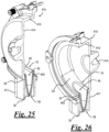
Fig. 25 is a right side perspective view in section of the outlet adapter ofFig. 21 ; -
Fig. 26 is a left side perspective view in section of the outlet adapter ofFig. 21 ; -
Fig. 27 is a bottom front perspective view of the flexible nozzle ofFig. 17 ; -
Fig. 28 is a top rear perspective view of the flexible nozzle ofFig. 27 ; -
Fig. 29 is a top plan view of the flexible nozzle ofFig. 28 ; -
Fig. 30 is a rear elevation view of the flexible nozzle ofFig. 28 ; -
Fig. 31 is a horizontal section view of the flexible nozzle ofFig. 28 , -
Fig. 32 is a bottom plan view of the flexible nozzle ofFig. 28 ; -
Fig. 33 is a front elevation view of the flexible nozzle ofFig. 28 ; -
Fig. 34 is a left side elevation view of the flexible nozzle ofFig. 28 ; -
Fig. 35 is a right side elevation view of the flexible nozzle ofFig. 28 ; -
Fig. 36 is a top plan view of a reference planar oval relative to the flexible nozzle ofFig. 28 ; -
Fig. 37 is a long side view in section of the flexible nozzle ofFig. 28 ; -
Fig. 38 is a short side view in section of the flexible nozzle ofFig. 28 prior to the flow of viscous food product; -
Fig. 39 is the flexible nozzle ofFig. 38 deformed during the flow of viscous food product; -
Fig. 40 a bottom view of the deformed valve of the nozzle ofFig. 39 ; -
Fig. 41 is a rear perspective view of an outlet adapter according to another embodiment of the present invention; -
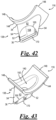
Fig. 42 is a bottom perspective view of the flexible nozzle ofFig. 18 ; -
Fig. 43 is a top perspective view of the flexible nozzle ofFig. 18 ; -
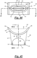
Fig. 44 is a top plan view of the flexible nozzle ofFig. 43 ; -
Fig. 45 is a front elevation view of the flexible nozzle ofFig. 43 ; -
Fig. 46 is a bottom plan view of the flexible nozzle ofFig. 43 ; -
Fig. 47 is a long side view in section of the flexible nozzle ofFig. 43 ; -
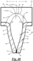
Fig. 48 is a short side view in section of the flexible nozzle ofFig. 43 prior to the flow of viscous food product; -
Fig. 49 is the flexible nozzle ofFig. 26 deformed during the flow of viscous food product; -
Fig. 50 is a bottom view of the flexible nozzle ofFig. 43 deformed during the flow of viscous food product; -
Fig. 51 is a cross sectional view of a front housing taken along line 51-51 ofFig. 53 ; -
Fig. 52 is a top perspective view of the front housing and transport device ofFig. 51 ; -
Fig. 53 is a top plan view of the transport device inside the front housing ofFig. 52 ; -
Fig. 54 is a sectional view taken along line 54-54 ofFig. 53 ; -
Fig. 55 is a sectional view taken along line 55-55 ofFig. 53 ; -
Fig. 56 is a perspective view of a first grinding plate showing three groups of circumferentially oriented teeth in one aspect of the subject technology; -
Fig. 57 is a perspective view of a second grinding plate showing one group of circumferentially oriented teeth in one aspect of the subject technology; -
Fig. 58A is a rear perspective view of a transport device with restraining receptacle in one aspect of the subject technology; -
Fig. 58B is a front perspective view of the transport device; -
Fig. 59A is a front view in section of a front housing with the transport device ofFig. 58A and showing the lock bolt in the free position; -
Fig. 59B is the front view in section ofFig. 59A showing the lock bolt in the locked position; -
Fig. 60 is a partial front perspective view of a viscous food product dispensing system showing an actuating lever and chopping bracket in one aspect of the subject technology; -
Fig. 61 is a left side perspective view in section of the dispensing system ofFig. 60 ; and -
Fig. 62 is a partial left side view in section of the dispensing system ofFig. 60 . - In the discussion that follows, like reference numerals are used to refer to like structures and elements in the various figures.
- The general arrangement of a viscous food product grinding and dispensing system 12 ("
system 12") of the present invention is shown inFigs. 1 & 2 .System 12 includes anoutlet adapter 610 having adischarge cover 614 with aspout 617.Discharge cover 614 is configured to house amilling device 618 and to be operatively connected to atransport section 28 ofsystem 12.Milling device 618 includes an opposing set of grinding members or plates, such as frontrotating grinder 619 and a rear fixedgrinder 621.Front rotating grinder 619 is adapted to rotate with respect to rear fixedgrinder 621. - In operation,
milling device 618 receives a supply flow ofparticulate food product 20 and processes the particulate food product into a pressurized supply flow ofviscous food paste 22 for dispensing throughspout 617 as anelongated stream 24.Food product 20 may include a variety of nuts, including peanuts and almonds.Viscous food paste 22 may include a variety of nut butters, such as peanut butter and almond butter. -
System 12 includes abin 26 for storage ofparticulate food product 20, gravity fedtransport section 28 that receives the particulate food product, and apower source 30 that drives atransport device 32 as well as millingdevice 618.Transport device 32 is located withintransport section 28 and operates to moveparticulate food product 20 downstream to millingdevice 618. -
Transport device 32 is an auger in one embodiment, which is designed to work in conjunction with the internal features oftransport section 28 in order to perform an initial processing of theparticulate food product 20. The initial processing involves a rough cutting and crushing of the product. The subsequent processing of the rough product involves relatively finer grinding performed by themilling device 618. - In the embodiment shown in
Figs. 1 and 2 , elongatedstream 24 is not pinched off or severed. Rather, the stream bifurcates upon cessation of flow leaving a residual, or dangle. In some embodiments, as described more fully herein, the outlet adapter further includes a flexible discharge nozzle adapted to pinch off or severstream 24 upon cessation of flow. - Now referring to
Fig. 3 , discharge cover 614 (viewed as if transparent) has a generally cylindrical shape and includes anannular sidewall 615,annular flange 622 at the rear, and anose 624 at the front.Transport section 28 includes asleeve 626, afront housing 628, arear plate 630, and achute inlet 632 extending from the top of the sleeve.Sleeve 626 further includes a pair of opposingnodes 634 configured to receive and secure opposing ends of aclamp bar 636.Nose 624 is configured to receive and secure a front portion ofclamp bar 636.Front housing 628 includes anannular perimeter 638 and anarm 640 extending from the top of the annular perimeter and connected to the front ofchute inlet 632. Apost 642 is fastened to the front ofarm 640. In assemblingdischarge cover 614 tofront housing 628, areceptor 644 on top ofannular flange 622 is first aligned with and inserted ontopost 642. Next,clamp bar 636 is secured tonose 624 and the ends of the clamp bar secured tonodes 634. Alternatively,discharge cover 614 is aligned againstfront housing 628, secured byclamp bar 636, and then post 642 is fastened toarm 640 throughreceptor 644. -
Bin 26 includes achute 646 at the bottom for discharge ofparticulate food product 20.Bin 26 further includes arotatable gate 648 configured to pivot from a normally closed position to an open position. In the closed position (Figs. 4 ,5 ),gate 648 covers the bottom opening ofchute 646, preventing discharge ofparticulate food product 20. In the open position (Fig. 3 ),gate 648 is pivoted away from the bottom opening ofchute 646 towards the front of the chute, thus allowing for product discharge. In assemblingbin 26 to transportsection 28,chute 646 is inserted intochute inlet 632. During insertion ofchute 646 the top ofarm 640 engages aflap 650, causing the front rotation ofgate 648. - Referring to
Figs. 4 and5 ,bin 26 may be removed fromtransport section 28 for cleaning and/or change-over of product. Upon removal ofchute 646 fromchute inlet 632,flap 650 rotates (either by gravity or spring assisted), thus pivotinggate 648 back to the closed position.Chute 646 further includes an opposing pair ofstops 652 positioned on the sides of the chute.Stops 652 define a limit of movement ofgate 648 in the closed position. Thus,gate 648 acts to minimize or substantially eliminate leakage of product from the bottom opening ofchute 646 during removal ofbin 26. - Referring to
Figs. 6A-6K , cutout portion 656 (aka over-center cutout) is disposed in the flights oftransport device 32. As exemplified inFig. 6B ,cutout portion 656 is disposed intransport device 32 in an over-center position.Cutout portion 656 is formed as a notch having two perpendicular sides of unequal length.Cutout portion 656 is aligned below the opening ofchute inlet 632. Those of skill in the art will appreciate that the dimensions ofcutout portion 656 are sized commensurate with a target product (e.g. almond, or peanut). In merely exemplary nonlimiting examples, dimensions of 7.637 mm and 16.665 mm are used. - Prior systems required pre-processed, partially broken product for adequate grinding. As shown in
Figs. 6G through 61 , the cutout of conventional systems cannot capture and break a whole nut because it pops out and escapes. While the over-center cutout portion shown inFigs. 6E & 6F , engages and breaks a whole nut against chamber wall (sleeve 626) has been found to be suitable for the processing of whole peanuts, it has been discovered that this arrangement is still limited when processing larger whole nuts, for example pistachios or almonds. - Referring to
Figs. 6K and7 , the rear portion offront housing 628 includes a plurality of radially equally spaced-apartflutes 658 disposed aroundtransport device 32.Flutes 658 are longitudinal recesses along a portion of the interior surface ofsleeve 626, configured in number and size to maximize product flow fromsleeve 626 forward toward millingdevice 618. In the embodiment shown inFig. 6K , the bottom threeflutes 658 extend rearwardly along the interior surface ofsleeve 626 below chute inlet 632 (see alsoFig. 6A ). - The number and size of flutes can be varied to adjust flow. In one example (
Fig. 7 ), five flutes, each being approximately 8mm in diameter, half depth, are utilized. In another example, 4 flutes are used which results in a lower flow rate and lower current draw on the motor. - Referring to
Figs. 8 and9 , a pair of opposing texture adjustment screws 660 accessible throughannular perimeter 638 allow adjustment of viscous food paste texture from coarse to fine. For nut products, the adjustments result in crunchy or creamy nut butter. Texture adjustment screws 660 are inserted through openings inannular perimeter 638 and are secured in corresponding helical slots within rear fixedgrinder 621. Adjustment is made by loosening texture adjustment screws 660 and rotating the rear fixedgrinder 621, relative to the longitudinal axis oftransport device 32, into the desired position closer or further away from frontrotating grinder 619, then re-tightening the texture adjustment screws. Preferably, the adjustment does not require the use of special tools, and the screws can be manually rotated. The top end of texture adjustment screws 660 may be any suitable type of thumb screw, such as including a knurled surface to allow ease of manual operation. - Referring to
Figs. 10 and11 , manual fasteners may be used for assembly and disassembly oftransport section 28,transport device 32, andoutlet adapter 610 frompower source 30. Assembly and disassembly without special tools acts to reduce device-cleaning time and product change-over time, and reduces the potential for loss of special tools. Referring toFig. 10 ,power source 30 is protected by anenclosure 662. Abacker plate 664 is secured toenclosure 662 via thumb screws 666. Aring 668 is placed in an opening inbacker plate 664, and ashaft 670 of a motor 672 (see motor inFig. 12 ) extends forward through the opening. - The rear end of
transport device 32 is secured toshaft 670 via screw set 674. Next,transport section 28 is inserted ontotransport device 32 andrear plate 630 is secured tobacker plate 664 viaknobs 676. Then the transport device is secured to the transport section viafastener set 678. The rear fixed grinder is secured tofront housing 628 via texture adjustment screws 660, as described above.Front rotating grinder 619 is inserted onto the front oftransport device 32, andoutlet adapter 610 is secured tofront housing 628 viapost 642 andclamp bar 636 as described above. Thus, as the front end oftransport device 32 is coupled to frontrotating grinder 619, the front rotating grinder is operably coupled topower source 30. - Referring to
Figs. 12 through 14 ,power source 30 further includes a variable frequency drive (VFD)controller 680 operatively connected tomotor 672.VFD controller 680 is in electrical communication withmotor 672 and operator interfaces, which include an on/off switch 684 (shown inFig. 10 ) and a time adjustment feature 686 (shown inFig. 13 ). -
VFD controller 680 enablesmotor 672 to operate using various world-wide input voltages and frequencies, and maintains improved torque and horsepower. Further,VFD controller 680 includes overload protection with single push button recovery and PLC controllability to provide specific user-selectable and customizable torque/speed profiles via computer program profiles. - In one embodiment, a 60Hz, 110 Volt, 3 phase, VFD controlled, 1.5hp motor is used. This arrangement allows high torque from a relatively smaller motor. Conventional systems utilize single phase motors that are necessarily larger. In another embodiment, a 230V, 50Hz system is provided. The following input power options are preferred: 110V / 60Hz, 220V / 60Hz, and 230V / 50Hz.
- Referring to
Fig. 13 , a group of toggle switches in the rear side ofenclosure 662 facilitates atime adjustment feature 686. The switches are operatively connected toVFD controller 680.Time adjustment feature 686 allows selection from a plurality of pre-determined run times formotor 672. For example, the pre-determined run times may be selected from a range of 15 seconds to 180 seconds.Time adjustment feature 686 is a "user-friendly" feature that takes the guess work out of adjusting unit run time. For example, it may include a series of four toggle switches, the first switch corresponding to 15 seconds, the second corresponding to 70 seconds, the third corresponding to 125 seconds and the fourth corresponding to 180 seconds run time. User positioning of on/offswitch 684 to the "on" position causes activation ofsystem 12 throughVFD controller 680. Activation ofsystem 12 causes motor 672 to operate for the maximum pre-determined run time, unless overridden by the user positioning the on/offswitch 684 to the "off' position. - The general arrangement of
alternative outlet adapters 100/410 for a viscous food product grinding and dispensingsystem 412 are shown inFigs. 15 and 16 according to various embodiments of the present invention.Outlet adapters 100/410 include adischarge cover 114/414 and aflexible nozzle 16/116. Discharge covers 114/414 are configured to house a milling device 418 (similar to milling device 618) and to receiveflexible nozzle 16/116.System 412 includes abin 26 for storage ofparticulate food product 20, gravity fedtransport section 28 that receives the particulate food product and apower source 30 that drives atransport device 432 as well as millingdevice 418.Transport device 432 is located withintransport section 28 and operates to moveparticulate food product 20 downstream to millingdevice 418. In operation,milling device 418 receives a supply flow ofparticulate food product 20 and processes the particulate food product into a pressurized supply flow ofviscous food paste 22 for dispensing throughnozzle 16/116 as anelongated stream 24. - Now referring to
Fig. 17 ,discharge cover 414, being similar to dischargecover 614, has a generally cylindrical shape and includes anannular sidewall 415.Discharge cover 414 also includes aspout 417 configured to act as an environmental guard and tamper deterrent for surroundedflexible nozzle 16. - The interior of
discharge cover 414 may be curved to align adjacent the outer curved surface of millingdevice 418.Milling device 418 includes a frontrotating grinder 419 and a rear fixedgrinder 421. -
Outlet adapter 410 also includes agasket 422 fastened to the rear ofdischarge cover 414 viafasteners 426.Gasket 422 provides improved sealing ofdischarge cover 414 against rear fixedgrinder 421. In assembly,discharge cover 414 withgasket 422 is aligned against afront housing 428, (may be secured byclamp bar 636, similar to discharge cover 614), and then post 440 is fastened tofront housing 428 throughreceptor 444.Post 440 andfasteners 426 are configured to allow for installation both manually and by use of tools. - Now referring to Figs. 18A, 18B and
19 ,transport device 432 is similar to transportdevice 32, except for including a hollow bore portion 454, and having two opposingcutouts 456 disposed at approximately 180 degrees out of phase, relative to each other.Cutouts 456 are aligned below the opening of achute inlet 434. - Referring to
Fig. 20 , in some embodiments,transport device 432 is solid, and does not include hollow bore portion 454. In one embodiment,transport device 432 is formed with an outer diameter of about 35.5 mm, andcutouts 456 are formed with a depth of about 7.637 mm and a width of about 16.665 mm. - Now referring to
Figs. 21-26 ,spout 417 extends from the bottom ofannular sidewall 415, and encloses all offlexible nozzle 16, except the bottom outlet.Spout 417 may be integral or ancillary tooutlet adapter 410. Referring toFigs. 24-26 ,nozzle 16 includes aproximal end 34, adistal end 36. Avalve 38 with a hollowinterior passage 40 is formed in the nozzle.Nozzle 16 is coupled at theproximal end 34 to anaperture 442 inannular sidewall 415 ofdischarge cover 414.Nozzle 16 includes a mountingflange 44 at theproximal end 34 configured to fit against the concave curved interior surface ofdischarge cover 414. As seen inFig. 21 ,discharge cover 414 may include ashoulder 446 configured to abut theouter edges 48 of mountingflange 44. As best seen inFigs. 34 and 35 , aperimeter edge 49 offlange 44 may include radius curved portions configured to seal against concave curved interior edge portions ofdischarge cover 414. -
Valve 38 is biased in a normally closed position and flexes to an open position due to a pressure exerted by the discharge ofviscous food paste 22 as it is forced downstream throughinterior passage 40, and returns to the normally closed position upon flow cessation.Valve 38 is configured with interior geometry features that pinch or chop againstelongated stream 24 as the valve returns to the closed position, effectively slicing through, pinching, or breaking apart the elongated stream. Pinchingelongated stream 24 withinvalve 38 reduces the amount of paste residue attached to the external face of the bottom of the valve after the valve returns to the closed position. - In some embodiments, the properties of
viscous food paste 22 allow for an alternative flexible nozzle to be utilized. Such flexible nozzle has a discharge opening that also enlarges, or deforms, due to product stream pressurization, and returns to the closed position upon flow cessation. The severing ofelongated stream 24 leaves substantially no paste residue attached to the external face of the bottom of the valve after the stream flow is de-pressurized. - In some embodiments, the properties of
viscous food paste 22 allow for an alternative rigid or semi-rigid nozzle to be utilized. Such properties ofviscous food paste 22 inherently result in a clean drop or severing ofelongated stream 24 due to forces of gravity once the supply flow is depressurized. Such natural severing ofelongated stream 24 leaves substantially no paste residue attached to the external face of the bottom of the valve after the stream flow is de-pressurized. In some embodiments, such clean droppingviscous food paste 22 may be dispensed with just the discharge cover in place, without any nozzle inserted. In some embodiments, the discharge cover does not utilizespout 417, and a separate, plastic sneeze guard (not shown) is supported in front of the discharge ofvalve 38. - In some embodiments, a suitable biasing device, such as a pinch roller set (not shown) is used to assist
flexible nozzle 16 in returning to its original, closed position after the stream flow is de-pressurized. In operation, once the stream flow is de-pressurized, the pinch roller set is activated adjacent toproximal end 34 ofvalve 38. The rollers of the pinch roller set are urged closer together to slightly compressvalve 38 as the rollers are moved downwardly towards thedistal end 36. Asvalve 38 returns to the closed position, elongatedstream 24 is severed, and leaves substantially no paste residue attached to the external face of the bottom of the valve. The pinch roller set is thereafter returned to a starting position. The operation of the pinch rollers can be achieved by various methods, including full or partial automation. - Referring to
Figs. 27-40 , mountingflange 44 includes anopening 50 atproximal end 34 ofinterior passage 40.Opening 50 has an ovoid shape and is configured to receiveviscous food paste 22.Interior passage 40 tapers asymmetrically in two dimensions (seeFIGS. 30 ,33-35 ) slightly from opening 50 downstream towarddistal end 36. -
Valve 38 includes a pair of opposingflap walls 52 joined by a pair of opposingside walls 54, the flap walls and side walls together forming continuousinterior passage 40. Referring toFig. 37 ,valve 38 has a side exterior linear dimension length "L" and a bottom exterior linear dimension width "W". In one embodiment, "L" and "W" are from about 1.65 inches to about 2.2 inches, and preferably "L" is about 2.0 inches and "W" is about 1.65 inches. Referring toFig. 38 ,valve 38 has an exterior linear dimension depth "D" of about 0.75 inches to about 1.25 inches, and preferably about 0.85 inches. - Referring to
Figs. 30 ,33 and36 , a referenceplanar oval 56 is visualized as located above opening 50, in the X-Y plane; the reference planar oval having a central X axis, Y axis and perpendicular Z axis.Opening 50 has a generally concave curvature about the Y axis configured to match the curvature ofannular sidewall 415 ofdischarge cover 414. To reduce pressure drop of the pressurized supply flow ofviscous food paste 22 throughopening 50, the interior transition fromflange 44 toside walls 54 andflap walls 52 is formed in a radius curvature. Referring toFigs. 29-39 , the transition fromflange 44 toside walls 54 has a generallyconvex curvature 58 relative to the Z axis and the transition from the flange toflap walls 52 has a generallyconvex curvature 60 relative to the Z axis. -
Valve 38 is biased in a normally closed position (seeFig. 38 ) and flexes to an open position (seeFig. 39 ) due to a pressure exerted by the discharge ofviscous food paste 22.Valve 38 has a generally duckbill shape, and includes asheath portion 62 and aflexible portion 64.Sheath portion 62 is located onside walls 54 and on the upper portion offlap walls 52. Onflap walls 52,flexible portion 64 forms acurved interface 65 withsheath portion 62.Sheath portion 62 is configured with a lesserinterior taper angle 66 from about 7 degrees to about 8 degrees relative to the Z axis.Flexible portion 64 is located onflap walls 52 and is configured with a greaterinterior taper angle 68. In one embodiment, the wall thickness offlexible portion 64 increases as it tapers towardsport 70. At the section center cut ofFig. 38 , the greaterinterior taper angle 68 is about 18 degrees and a greaterexterior taper angle 69 is from about 11 degrees to about 14 degrees, relative to the Z axis.Flexible portion 64 is configured to be biased in a normally closed position and flexes outward slightly toward the exterior as the pressurized supply flow ofviscous food paste 22 is forced downstream through interior passage 40 (seeFig. 39 ). -
Interior passage 40 is defined by opening 50 and the proximal ends 34 offlap walls 52, having a generally ovoid cross-section about the Z axis, that gradually decreases in cross sectional area downwardly (along the Z axis) towards a normally closedport 70 offlexible nozzle 16 atdistal end 36.Port 70 is configured for operation from the biased normally closed position to the open position for discharge ofviscous food paste 22 in theelongated stream 24.Elongated stream 24 may be captured by the user within a container below port 70 (seeFig. 15 ). -
Port 70 is configured such that the force from the pressurized supply flow ofviscous food paste 22 urges the port open and once the supply flow is depressurized and the force ceases, the removal of the force causes the port to return to the normally closed position (Fig. 38 ).Port 70 will move to the open position when the product processing pressure of the supply flow ofviscous food paste 22 reaches a predetermined valve threshold pressure, and will return to the closed position when the product processing pressure falls below the valve threshold pressure. - Each
flexible portion 64 includes opposing pairs of taperedstiffening portions 71 adjacent toside walls 54. At eachside wall 54adjacent stiffening portions 71 taken together are configured to be from about two-thirds to about one-half of the width ofport 70 atdistal end 36, and are configured to assist in biasing the port into the closed position. -
Port 70 includes a pair of opposinggates 72 at thedistal end 36 of the interior surfaces offlap walls 52. In the closed position,gates 72 have the appearance of a substantially closed elongated slit. Asgates 72 are forced open by the pressurized supply flow ofviscous food paste 22 to form anoutlet 74. As the slit opens, the middle portion thereof opens relatively more than the end portions to form a bulbousmiddle portion 75. In other words,gates 72 each deform in a generally bell-like, somewhat concave curvature, to form an ovaloid shapedmiddle portion 75 of outlet 74 (seeFig. 40 ). -
Valve 38 ofnozzle 16 is configured to reduce the amount of paste residue attached toexternal face 76 by effectively severing theelongated stream 24 without causing excessive pressure drop when the valve is in the open position. - Referring to
Fig. 38 ,gates 72 are configured to be angled slightly relative to each other along the X axis from apinch point 78 down towards a gap atoutlet 74, and thus are biased to abut close together at the pinch point whenport 70 is in the normally closed position. As such,gates 72 ofport 70 are configured to pinch or chop againstelongated stream 24 as the port returns to the closed position, effectively slicing through or breaking apart the elongated stream. The severedelongated stream 24 falls into the user's container below, thereby reducing the amount of residueviscous food paste 22 remaining attached toexternal face 76 ofport 70. - Now referring to
FIGS. 41-50 , in an alternative embodiment, anoutlet adapter 100 includes adischarge cover 114 and aflexible nozzle 116.Nozzle 116 has many similar features tonozzle 16 described above (seeFigs. 27-40 ).Nozzle 116 is coupled at theproximal end 34 to anaperture 42 inannular sidewall 115 ofdischarge cover 114.Nozzle 116 includes avalve 138 and a mountingflange 144 at theproximal end 34 configured to fit against the concave curved interior surface ofdischarge cover 114.Discharge cover 114 may include ashoulder 146 configured to abut theouter edges 148 of mountingflange 144. Referring toFig. 43 , mountingflange 144 includes anopening 150 atproximal end 34 of aninterior passage 140 configured to receiveviscous food paste 22. -
Valve 138 is biased in a normally closed position (seeFig. 48 ) and flexes to an open position (seeFig. 49 ) due to a pressure exerted by the discharge ofviscous food paste 22.Valve 138 has a generally duckbill shape, and includessheath portion 62 and aflexible portion 164. Onflap walls 52,flexible portion 164 forms acurved interface 165 withsheath portion 62. -
Interior passage 140 is defined by opening 150 and the proximal ends 34 offlap walls 52, having a generally ovoid cross-section about the Z axis, that gradually decreases in cross sectional area downwardly (along the Z axis) towards a normally closedport 170 offlexible nozzle 116 atdistal end 36.Port 170 is configured for operation from the biased normally closed position to the open position for discharge ofviscous food paste 22 in theelongated stream 24. -
Port 170 includes a pair of opposinggates 172 at thedistal end 36 of the interior surfaces offlap walls 52. In the closed position,gates 172 have the appearance of a closed slit. Asgates 172 are forced open by the pressurized supply flow ofviscous food paste 22 to form anoutlet 174. As the slit opens, the middle portion thereof opens relatively more than the end portions to form a bulbousmiddle portion 175. In other words,gates 172 each deform in a generally bell-like, somewhat concave curvature, to form an ovaloid shapedmiddle portion 175 of outlet 174 (seeFig. 50 ). -
Gates 172 are configured to be substantially parallel, and are further configured to be biased to abut together whenport 170 is in the normally closed position. As such,gates 172 ofport 170 are configured to pinch or chop againstelongated stream 24 as the port returns to the closed position, effectively slicing through or breaking apart the elongated stream. The severedelongated stream 24 falls into the user's container below, thereby reducing the amount of residueviscous food paste 22 remaining attached to anexternal face 176 ofport 170. -
Nozzles particulate food products 20. The nozzle material may be configured of a durometer hardness to match the type of product used for milling, and the type ofviscous food paste 22 produced by the viscous food product grinding and dispensingsystem 12. The durometer hardness utilized is coordinated to allow thevalves interior passages elongated stream 24 is also taken into account with the selection of rubber durometer. In one embodiment, larger sized peanuts produced a rate of about 1.3 lbs/minute to about 1.4 lbs/minute. In another embodiment, smaller sized peanuts produced a rate of about 3.1 lbs/minute to about 3.6 lbs/minute. In one embodiment,flexible nozzle 116 is preferably made from Shore 80A rubber for use in peanut butter applications to produce a flow rate of about 1.5 to about 3.4 lbs/minute of peanut food paste. The Shore 80Aflexible nozzle 116 produces a dispense rate from about 3.2 to 3.4 lbs/minute with smaller sized peanuts and from about 1.5 to 1.7 lbs/minute with larger sized peanuts. - Discharge covers 114, 414, 614 may be made from a suitable food grade metal, such as stainless steel for example.
Flexible nozzles aperture 42 in discharge covers 114, 414, 614. Various parts shown are interchangeable in different system embodiments. For example,transport device 432 may be used withinfront housing 628. - Although shown coupling with the
annular sidewall U-shaped flanges valves Valves valves - In one aspect of the subject technology, a viscous food product dispensing system comprises a
transport section 28 having achute inlet 632 for receiving a particulate food product, and atransport device 32 adapted to process and longitudinally convey the received particulate food product. In this context, "adapted to" means thattransport device 32 is designed and constructed to include an auger-like function so as to convey the food product longitudinally. In one aspect, such conveyance is from thetransport section 28 intooutlet adapter 610. In one aspect, food product is conveyed longitudinally from the transport section intooutlet adapter 610 through one ormore flutes 658. - In one aspect, the
transport device 32 has anover-center cutout 656 operatively aligned with thechute inlet 632. As depicted in Figs. 60A & 60B,over-center cutout 656 is disposed along a portion oftransport device 32. As depicted inFig. 6D ,over-center cutout 656, as viewed in cross section, extends over, or past, thecenterline 33 oftransport device 32. - As shown in
Fig. 52 ,over-center cutout 656 is operatively aligned withchute inlet 632 so that food product (e.g. nuts) enterchute inlet 632 and are thereafter engaged bycutout 656, and processed (e.g. crushed), astransport device 32 longitudinally conveys the processed food product. Those of skill in the art will appreciate the auger-like function of longitudinal conveyance performed bytransport device 32. In one aspect,transport device 32 is operatively engaged with one ormore flutes 658. -
Fig. 51 depicts a cross-sectional view showingtransport device 32 disposed between sleeveinner wall 627 ofsleeve 626 and opposing sleeveinner wall 629 ofsleeve 626. As shown, sleeveinner wall 627 ofsleeve 626 and opposing sleeveinner wall 629 ofsleeve 626 are substantially vertical and each transition to a taperedupper portion - In one aspect, as depicted in
Fig. 51 , thesleeve 626 is configured with aninner sleeve wall 627. Theinner sleeve wall 627 is spaced apart from thetransport device 32 in a region about theover-center cutouts 656. The inventors have recognized that while in previous dispensers the taperedupper portions sleeve 626 helped to direct food product towards thetransport device 32, it has been discovered that despite the previously disclosed advantages of theover-center cutouts 656, that larger whole nuts, including, but not limited to pistachios and almonds require aprocessing zone 708 adjacent thetransport device 32 within which they can be trapped and broken by thetransport device 32. InFigure 51 , thetransport device 32 exemplarily rotates in the direction ofarrow 707, this rotation draws the whole nuts into theprocessing zone 708 which may include a portion of the associatedflute 658. As seen inFig. 51 , theinner sleeve wall 627 is located exterior of the associatedflute 658 in a direction from thetransport device 32. That is, theinner sleeve wall 627 is further from a center-line of thetransport device 32 than the associatedflue 658. The whole nuts are broken between aprocessing surface 802 formed in theinner sleeve wall 627 in theprocessing zone 708 and theflights 712 of thetransport device 32 at theover-center cutouts 656. Further aspects of this are depicted inFigs. 52-59 . -
Figure 52 is a perspective view of thetransport section 28.Figure 53 is a top view of thetransport section 28 ofFig. 52 .Fig. 51 is a cross-sectional view taken along line 51-51 ofFig. 53 .Figs. 54 and55 are other cross-sectional views of thetransport section 28 as noted inFig. 53 . ComparingFigs. 51 ,54 , and55 . It can be seen that a portion of the flutes are formed into thelower portion 709 of thesleeve 626 adjacent to thetransport device 32. As seen from comparison ofFig. 55 to Fig. 51 , as well as inFigs. 52 and53 , thelower portion 709 includes ataper 711 from aback end 713 of thelower portion 709 towards anoutlet aperture 710 through which theflutes 658 and thetransport device 32 extend. -
Figure 56 depicts an example of afirst grinding plate 653 andFigure 57 depicts an example of asecond grinding plate 654. In one aspect,transport device 32 is adapted to convey the received particulate food product from thetransport section 28 into an outlet adapter 610.Theoutlet adapter 610 includes adischarge cover 614 that encloses amilling device 618. Themilling device 618 includes grindingplates plates grinding teeth 620. It is to be understood that the term "milling device" is interchangeable with "grinding device" as used herein. - The milling device is adapted to further process the particulate food product into a viscous food paste. In this context, "adapted to" means that milling
device 618 converts the received food product into a viscous food paste by grinding the food product between grinding plates. In one aspect, the conversion is achieved by cooperating grinding plates, one being stationary and the other being rotatable so as to grind the food product. - The grinding
plates plate 653 is stationary and grindingplate 654 is rotatable relative to the grindingplate 653. In another aspect, this may be reversed. In yet another aspect, both plates rotate, relative to each other, at varying speeds and directions. - The consistency and/or viscosity of the food product (e.g. nut butter) can be adjusted by varying the amount of energy transferred to the food product. One such method of accomplishing this is to vary the number and arrangement of grinding teeth on the various grinding plates.
- The size, location, and relative size of grinding
teeth 620 are adjusted according to multiple variables (aka commensurate with a food product). As a non-exhaustive example, the grinding plates (as described herein) can be tuned to nuts of various sizes so as to effect the viscosity and/or consistency of nut butter. By removing one or more rows of teeth form the rotating grinding plate or stationary grinding plate, the amount of work done can be tuned to meet the needs of the product for desired end product consistency. This may be useful, for example, in order to adjust the grindingplates - In one aspect, a method for adjusting the consistency and/or viscosity of a food product comprises the steps of: obtaining a viscous food product dispensing system comprising: a
transport section 28 having achute inlet 632 for receiving a particulate food product, atransport device 32 being adapted to convey the received particulate food product from thetransport section 28 into anoutlet adapter 610, theoutlet adapter 610 comprising adischarge cover 614 enclosing amilling device 618, themilling device 618 comprising front and rear grindingplates grinding teeth 620; and varying the location and/or number of the one or more grinding teeth according to multiple variables of a food product. - In one aspect, two or more of the grinding teeth are arranged circumferentially around either or both of the front or rear grinding plates. In one aspect, the grinding
teeth 620 of either or both of the grindingplates - In one aspect, the grinding teeth of either or both of the grinding
plates 635, 654 are arranged in one or more groups of circumferentially orientedteeth 620 being disposed radially outside of one or more linear rows of teeth, each row having two or more teeth aligned radially outwardly from a center of the respective grinding plate, and if more than one row, the rows being circumferentially spaced apart. - As shown in
Fig. 61 , afirst grinding plate 653 in one aspect has three groups of circumferentially orientedteeth 620, the groups being concentrically arranged, and disposed radially outside of four linear rows of teeth, each row having two teeth aligned radially outwardly from a center of the respective grinding plate, the four rows being circumferentially spaced apart. - As shown in
Fig. 62 , asecond grinding plate 654 in one aspect has one group of circumferentially orientedteeth 620 being disposed radially outside of four linear rows of teeth, each row having two teeth aligned radially outwardly from a center of the respective grinding plate, the four rows being circumferentially spaced apart. - It should be noted that first and second grinding
plates plates teeth 620 are intended for use in all of the foregoing, in the various aspects of the subject technology as described herein. Grindingplate 654 is designed to tune the amount of work introduced to the product to yield desired viscosity of end product. - In one aspect,
front grinding plate 619 is threadedly connected toproximal end 687 oftransport device 32, such that the front grinding plate is removed from the transport device in a removal direction. In one aspect, the threaded connection offront grinding plate 619 toproximal end 687 oftransport device 32 comprises a direct connection whereas in other aspects an intermediate connector can be used to accomplish the same functionality. It should also be noted that the subject technology can be configured such that the "removal direction" can be either clockwise or counterclockwise. In one aspect,transport device 32 andfront grinding plate 619 rotate in a counterclockwise direction to grind food product, and the threaded connection betweenfront grinding plate 619 andtransport device 32 is such that the removal direction is also counterclockwise; i.e.front grinding plate 619 is tightened in a clockwise direction. -
Figs. 58A and 58B depict left and right perspective views of an example of atransport device 32, including theflights 712 and theover-center cutout 656. In one aspect,distal end 688 oftransport device 32 has areceptacle 689 for operatively engaging alock pin 690. Thedistal end 688 oftransport device 32 may be relatively smooth (exclusive of receptacle 689) and does not include structure to realize auger functionality.Receptacle 689 is adapted to restrain (aka in a locked position)transport device 32 from rotating in the removal direction whenlock pin 690 is inserted within the receptacle 689 (e.g.Fig. 59B ), and thereceptacle 689 is adapted to allow thetransport device 32 to rotate in a counter-removal direction when thelock pin 690 is inserted within thereceptacle 689. It should be noted that the insertion oflock pin 690 intoreceptacle 689 can be manual (e.g. a user engagement), or automatic (e.g. in response to a predetermined event, or series of events). - In one aspect,
receptacle 689 is adapted to eject thelock pin 690 when thetransport device 32 is rotated in the counter-removal direction. In one aspect (e.g.Fig. 59B ),receptacle 689 has alower surface 691 adjacent to a restrainingwall 692.Lock pin 690 engages restrainingwall 692 whenlock pin 690 is inserted within thereceptacle 689 and thetransport device 32 is rotated in the removal direction, andlower surface 691 ejectslock pin 690 when thetransport device 32 is rotated in the counter-removal direction. - In one aspect (e.g.
Fig. 59B ),distal end 688 oftransport device 32 has asecond receptacle 693 for operatively engaging alock pin 690. In one aspect (e.g.Fig. 59B ), thesecond receptacle 693 is disposed one hundred and eighty degrees relative to thefirst receptacle 689, but is otherwise substantially identically shaped. It should be noted that, in the configuration depicted in Fig. 64B, only onelock pin 690 is used and thus will only engage one of the tworeceptacles - From the perspective of a user standing in front of the milling device,
front grinding plate 619 rotates in counterclockwise direction to grind a food product. In this aspect, the threaded connection between the auger (aka transport device 32) and grinding plate is such that the plate is unscrewed in a counterclockwise direction, so that the plate is not unscrewed during operation, i.e. when the auger rotates in counterclockwise direction, the force is in a direction that would cause the plate to be tightened. To remove the plate, lock pin 690 (aka "locking pin", "anti-rotation pin") is moved into a locked position and engaged (manually in one aspect) intoreceptacle 689. As shown in Figs. 64A&B, counterclockwise rotation is restrained or locked, while clockwise rotation ejectslock pin 690, moving thelock pin 690 into an unlocked position. An important advantage is thereby achieved because a user cannot accidentally damagelock pin 690 by applying excessive force in a counter-removal direction when screwing thefront grinding plate 619 onto thetransport device 32. - As shown in
Figs. 60-62 , a viscous food product dispensing system in one aspect includes atransport section 28 having achute inlet 632 for receiving a particulate food product. Atransport device 32 moves the received particulate food product from the transport section into anoutlet adapter 610. Theoutlet adapter 610 includes adischarge cover 614 enclosing amilling device 618. The milling device being adapted to process the particulate food product into a pressurized flow of viscous food paste that is discharged through anozzle 16, the nozzle being disposed through thedischarge cover 614. Thenozzle 16 is partially covered by aspout 417. Aproximal end 704 of anactuating lever 699 is operatively connected to the transport section, theactuating lever 699 is movable between engaged and disengaged positions. In one aspect, amedial portion 705 of theactuating lever 699 is adapted to activate (e.g. turn on, engage) apush button 694 when theactuating lever 699 is in the engaged position. - In one aspect, a
chopping bracket 698 is operatively connected to themedial portion 705 of theactuating lever 699, and adistal end 706 of thechopping bracket 698 protrudes through aslot 703 disposed in thespout 417. In the disengaged position, thedistal end 706 of thechopping bracket 698 cuts off the pressurized flow of viscous food paste that is discharged through thenozzle 16. An important aspect is thereby achieved because undesirable "dangle" of food product that would otherwise remain upon cessation of flow, is prevented. - In one aspect, the
chopping bracket 698 is pivotably connected to themedial portion 705 of theactuating lever 699 by one or more pull outpins 697 so that thedistal end 706 of thechopping bracket 698 protrudes through aslot 703 in a reciprocating manner as theactuating lever 699 is moved between engaged and disengaged positions. Those of skill in the art will appreciate that various linkages and brackets can be used to achieve this functionality. - In one aspect, the
proximal end 704 of theactuating lever 699 is pivotably connected to thetransport section 28. In another aspect, theproximal end 704 of theactuating lever 699 is connected to anactuator base frame 696, and theactuator base frame 696 is pivotably connected to the transport section. It should be noted that the operative connection as herein described is intended to allowactuating lever 699 to cause thedistal end 706 of thechopping bracket 698 to cut off the pressurized flow of viscous food paste that is discharged through thenozzle 16, and additionally in one aspect, to activatepush button 694 as theactuating lever 699 moves between engaged and disengaged positions. - In one aspect, a push
button actuating pin 695 is disposed proximate themedial portion 705 of theactuating lever 699 so as to operatively engage and activate thepush button 694 when theactuating lever 699 is in the engaged position. - In one operational aspect, a
cup 700 is forcibly held under thenozzle 16 so as to move thedistal end 701 of the actuating lever 699 (typically biased in the disengaged position) in the direction of arrow 702 (Fig. 67), which causes theactuating lever 699 to be moved to the engaged position. In the engaged position, thedistal end 706 of thechopping bracket 698 is positioned to allow flow throughnozzle 16, andpush button 694 is activated thereby causing the flow of food product from thenozzle 16. Upon removal of thecup 700, theactuating lever 699 is moved to the disengaged position and thedistal end 706 of thechopping bracket 698 is moved so as to cut off the pressurized flow of viscous food paste that is discharged through thenozzle 16, thereby pinching off, or severing the product flow. - Some embodiments can include a combination of features that work in unison to provide an adaptable viscous food dispensing system that may be used with a variety of different food products. By combining a transport section with a sleeve having an asymmetrical cross section (see, for example,
Fig. 51 ) with an outlet adaptor that can use grinding plates with different grinding tooth configurations, a viscous food dispensing system can be used to process and grind whole nuts into a viscous food product with a high or low viscosity. - For example, as illustrated in
Figs. 53-57 , a viscousfood dispensing system 12 can be configured to process particulate food product that is captured in aprocessing zone 708 between thetransport device 32 and aprocessing surface 802. Theprocessing surface 802 can extend downward from the taperedupper portion 631 of thechute inlet 632 towards the curvedlower portion 709 of thesleeve 626, and may run longitudinally along at least a portion of the length of thesleeve 626 and thetransport device 32. Theprocessing surface 802 is formed in theinner sleeve wall 627 so that the width of theprocessing zone 708 is larger than the distance between thetransport device 32 and theside wall 629 of thesleeve 626 opposite theprocessing surface 802. The large width of theprocessing zone 708 may be useful, for example, in order to capture and process whole nuts (e.g., almonds). As thetransport device 32 rotates in a counterclockwise direction, the particulate food product within theprocessing zone 708 can be captured between theflights 712 and aleading edge 804 of theover-center cutout 656 and theprocessing surface 802, causing the captured particulate food product to be broken up into smaller pieces. Those smaller pieces can then be conveyed from thesleeve 626 to theoutlet adaptor 610 for grinding. - Use of a
transport device 32 that includes apin receptacle 689 and alock pin 690 that is slidably revived in the sleeve 626 (see, for example, Figs. 63A-64B) can be useful, for example, to allow a user to remove and attach various different grinding plates to thetransport device 32 without the use of specialized tools. This may allow a user of thesystem 12 to quickly adjust for different types of particulate food product, or to increase or decrease the viscosity of the viscous food product produced by thesystem 12. When implemented in asystem 12 with atransport device 32 andsleeve 626 that provide awide processing zone 708, a single viscousfood dispensing system 12 can be used with a wide variety of different particulate food products, both large and small, to produce viscous food products having a variety of different consistencies and viscosities. - While this invention has been shown and described with respect to detailed embodiments thereof, it will be understood by those skilled in the art that changes in form and detail thereof may be made without departing from the scope of the claims of the invention.
Claims (14)
- A viscous food dispensing system (12) comprising:a chute inlet (632) configured to funnel whole food product into a sleeve (626);an auger (32) configured to rotate within the sleeve, the auger having an over-center cutout;a processing surface (802) extending downward from the chute inlet towards a curved base of the sleeve along a portion of the auger, the processing surface being spaced laterally apart from the auger to define a processing zone (708) between the processing surface and the auger;a lock pin (690) slidably received in the sleeve and movable between a locked position in which the lock pin engages the auger to restrict rotation of the auger, and an unlocked position in which the lock pin is disengaged from the auger, wherein the lock pin engages a pin receptacle (689) formed in a radially-outward facing surface of the auger when in the locked position and engagement between the lock pin and the pin receptacle inhibits rotation of the auger in a first direction while allowing rotation of the auger in a second direction opposite the first direction;a stationary grinding plate (653) having at least one set of grinding teeth and a movable grinding plate (654) having at least one set of grinding teeth (620), the movable grinding plate (654) selected for the at least one set of grinding teeth (620) for a viscosity of a viscous food product, the movable grinding plate (654) coupled to a proximal end of the auger so that the movable grinding plate rotates with the auger relative to the stationary grinding plate;an outlet adaptor (610) that includes the stationary grinding plate (653) and the movable grinding plate (654), and the at least one set of grinding teeth on the movable grinding plate move relative to the at least one set of grinding teeth on the stationary grinding plate to grind the particulate food product into a viscous food product while the movable grinding plate is rotating (610);wherein the whole food product is broken into particulate food product as the whole food product is captured between a leading edge of the over-center cutout (656) and the processing surface while the auger is rotating, the auger configured to move the particulate food product away from the chute inlet to the movable grinding plate and the stationary grinding plate.
- The viscous food dispensing system of claim 1, wherein the movable grinding plate is secured to the auger by a threaded connection; and
wherein engagement between the lock pin (690) and the pin receptacle (689) prevents the auger from rotating in the first direction with the movable grind plate (654) as the movable grind plate is unscrewed from the auger and allows the auger to rotate in the second direction with the movable grind plate to prevent overtightening as the movable grind plate is screwed onto the auger. - The viscous food dispensing system of any of claims 1-2, wherein the number of teeth (620) and spacing between the teeth in each of the sets of grinding teeth can be selected based on a desired viscosity of the viscous food product
- The viscous food dispensing system of any of claims 1-3, wherein the teeth in each of the sets of grinding teeth are arranged in a circular pattern so that each set of grinding teeth on the stationary grinding plate (653) forms a circle that is concentric with each set of grinding teeth on the movable grinding plate (654).
- The viscous food dispensing system of any of claims 1-4, further comprising:a nozzle (16) arranged relative to the stationary grinding plate (653) and the movable grinding plate (654), the nozzle configured to dispense the viscous food product therethrough;an actuating lever (699) pivotably connected relative to the nozzle, the actuating lever movable between an engaged position wherein movement of the auger and the movable grinding plate is actuated and a disengaged position;a chopping bracket (698) connected to the actuating lever and movable in a reciprocating manner with the actuating lever such that the chopping bracket extends across a portion of the nozzle, at least partially occluding the viscous food product when the actuating lever is in the disengaged position.
- The viscous food dispensing system of any of claims 1-5, wherein a width of the processing zone (708) is larger than a distance between the auger (32) and a sleeve side wall opposite the processing surface.
- The viscous food dispensing system of claim 6, wherein the food processing zone further comprises at least one flute (658) that extends into the sleeve from the curved base.
- The viscous food dispensing system of claim 7, wherein the processing surface is exterior the at least one flute from the auger.
- A method for tuning a viscous food dispensing system (12) configured to grind particulate food product into viscous food product between a stationary grinding plate (653) and a movable grinding plate (654) configured to be rotated by a transport device (32), the method comprising:determining a desired viscosity of the viscous food product;uncoupling the movable grinding plate (654) from the transport device (32) to remove the movable grinding plate from the viscous food dispensing system, comprising:moving a lock pin (690) from an unlocked position to a locked position to restrict rotation of the transport device (32) in a first direction;after moving the lock pin (690) to the locked position, rotating the transport device until the lock pin engages a pin receptacle (689) formed in the transport device; andunscrewing the movable grinding plate by rotating it in the first direction;selecting a replacement movable grinding plate having at least one set of grinding teeth (620) for the desired viscosity of the viscous food product; andsecuring the replacement movable grinding plate to the drive device to tune the viscous food dispensing system based on the desired viscosity.
- The method of claim 9, wherein the step of selecting a replacement movable grinding plate includes selecting a replacement movable grind plate based on at least one of a desired number of grinding teeth (620) on the replacement movable grinding plate and a desired spacing of grinding teeth on the replacement movable grinding plate.
- The method of any of claims 9-10, wherein the movable grinding plate is coupled to the transport device by a threaded connection so that the step of uncoupling the movable grinding plate includes rotating the movable grind plate in a first direction to unscrew the movable grinding plate from the drive device; and
wherein the engagement between the lock pin and the pin receptacle inhibits rotation of the transport device in the first direction. - The method of any of claims 9-11, wherein the step of securing the replacement movable grinding plate to the drive device includes rotating the replacement movable grinding plate in a second direction to screw the replacement movable grinding plate onto the drive device; and
wherein engagement between the lock pin and the pin receptacle allows the drive device to rotate in the second direction to prevent overtightening of the replacement movable grinding plate. - The method of any of claims 9-12, wherein the transport device comprises an auger configured to convey the particulate food product to the fixed grinding plate and the movable grinding plate as the auger rotates; and
wherein the movable grinding plate is coupled to a proximal end of the auger by a threaded connection. - The method of claim 13, wherein the auger incudes an over-center cutout (656) and is configured to rotate within a sleeve (626) to process the particulate food product as the particulate food product is captured between a leading edge of the over-center cutout and a processing surface (802);wherein the processing surface is spaced laterally apart from the transport device to define a processing zone (708) between the processing surface and the auger; andwherein a width of the processing zone is larger than a distance between the auger and a sleeve side wall opposite the processing surface.
Applications Claiming Priority (3)
| Application Number | Priority Date | Filing Date | Title |
|---|---|---|---|
| US201962818012P | 2019-03-13 | 2019-03-13 | |
| US16/816,647 US11440018B2 (en) | 2019-03-13 | 2020-03-12 | Viscous food product grinding and dispensing system |
| PCT/US2020/022666 WO2020186177A1 (en) | 2019-03-13 | 2020-03-13 | Viscous food product grinding and dispensing system |
Publications (3)
| Publication Number | Publication Date |
|---|---|
| EP3938113A1 EP3938113A1 (en) | 2022-01-19 |
| EP3938113A4 EP3938113A4 (en) | 2022-12-21 |
| EP3938113B1 true EP3938113B1 (en) | 2024-03-13 |
Family
ID=72423919
Family Applications (1)
| Application Number | Title | Priority Date | Filing Date |
|---|---|---|---|
| EP20769991.9A Active EP3938113B1 (en) | 2019-03-13 | 2020-03-13 | Viscous food product grinding and dispensing system |
Country Status (3)
| Country | Link |
|---|---|
| US (1) | US11440018B2 (en) |
| EP (1) | EP3938113B1 (en) |
| WO (1) | WO2020186177A1 (en) |
Families Citing this family (3)
| Publication number | Priority date | Publication date | Assignee | Title |
|---|---|---|---|---|
| US11503800B2 (en) * | 2019-05-30 | 2022-11-22 | Osborne Industries Inc. | Animal feed mechanism with feed agitator assembly |
| CN112934374B (en) * | 2021-01-28 | 2023-11-28 | 滁州学院 | Lotus lipstick preparation equipment and preparation method |
| CN113001656B (en) * | 2021-02-24 | 2023-08-11 | 重庆市梁平区掌厨餐饮有限公司 | A dried fruit slotting device for food processing with controllable cutting length |
Family Cites Families (25)
| Publication number | Priority date | Publication date | Assignee | Title |
|---|---|---|---|---|
| US3827644A (en) * | 1969-02-19 | 1974-08-06 | Defibrator Ab | Grinding apparatus |
| US3666186A (en) * | 1970-07-20 | 1972-05-30 | Carroll B Hoffman | Thin film mill |
| DE2641395A1 (en) * | 1976-04-20 | 1977-11-03 | Toshio Yagi | WASTE DISPOSAL DEVICE |
| US4039153A (en) * | 1976-04-26 | 1977-08-02 | Hoffman Douglas L | Grinding mill |
| US4027824A (en) * | 1976-06-07 | 1977-06-07 | Grindmaster Of Kentucky, Incorporated | Nut grinding mill |
| US4253613A (en) * | 1978-02-17 | 1981-03-03 | Reinhall Rolf Bertil | Method and apparatus for controlling the effect of the centrifugal force on the stock in pulp defibrating apparatus |
| US4201349A (en) * | 1978-11-13 | 1980-05-06 | General Nutrition Corporation | Food retailing grinding machine |
| US5971307A (en) * | 1998-02-13 | 1999-10-26 | Davenport; Ricky W. | Rotary grinder |
| US5509610A (en) * | 1994-01-27 | 1996-04-23 | Gibbco, Inc. | Centrifugal chopping and grinding apparatus |
| US5553792A (en) * | 1995-06-02 | 1996-09-10 | Romer Labs, Inc. | Variable analytical sampling mill and method |
| US5707016A (en) * | 1996-07-01 | 1998-01-13 | Witsken; Anthony | Apparatus and methods for wet grinding |
| US5769335A (en) * | 1997-01-31 | 1998-06-23 | Tennessee Technological University | Method and apparatus for shear pulverization of polymer materials |
| US5927628A (en) * | 1998-03-03 | 1999-07-27 | Dallas A. C. Horn & Co. | Grinding apparatus for foodstuffs |
| US5979809A (en) * | 1998-03-13 | 1999-11-09 | J & L Fiber Services Inc | Refiner disc removal method and device |
| US6238267B1 (en) * | 1999-05-18 | 2001-05-29 | R & D Technology, Inc. | Grinding devices for rubber comminuting machines |
| SE521848C2 (en) * | 2002-04-02 | 2003-12-09 | Metso Paper Inc | Method and apparatus for measuring power stress at refiners |
| US7252033B1 (en) * | 2006-03-14 | 2007-08-07 | Uni-Splendor Corp | Automatic coffee maker |
| US7874505B1 (en) * | 2007-08-31 | 2011-01-25 | Food Equipment Technologies Company, Inc. | Food grinder with electronically adjustable grind settings, tooless disassembly |
| US20110062190A1 (en) * | 2009-09-11 | 2011-03-17 | Trade Fixtures, Llc | Bulk product dispenser having a container-activated dispensing actuator release assembly |
| US9386744B2 (en) * | 2011-12-16 | 2016-07-12 | Easy Trim, Llc | Plant trimming apparatus and methods of using the same |
| US9522399B2 (en) * | 2012-03-09 | 2016-12-20 | Whirlpool Corporation | Food processor and adjustable cutting assembly |
| KR20150038139A (en) * | 2012-07-24 | 2015-04-08 | 네퓨레 코포레이션 | Method for operating food mill |
| EP3119208B1 (en) * | 2014-03-20 | 2017-12-06 | Evolution S.r.l. | Improved metal surfaces anti-rub apparatus |
| US10843203B2 (en) * | 2016-03-17 | 2020-11-24 | Trade Fixtures, Llc | Viscous food product grinding and dispensing system |
| KR101935150B1 (en) * | 2017-05-19 | 2019-01-03 | 윤혁범 | Grinding blade using vertical rollers and grinder having the same |
-
2020
- 2020-03-12 US US16/816,647 patent/US11440018B2/en active Active
- 2020-03-13 WO PCT/US2020/022666 patent/WO2020186177A1/en not_active Ceased
- 2020-03-13 EP EP20769991.9A patent/EP3938113B1/en active Active
Also Published As
| Publication number | Publication date |
|---|---|
| US11440018B2 (en) | 2022-09-13 |
| US20200290054A1 (en) | 2020-09-17 |
| EP3938113A4 (en) | 2022-12-21 |
| WO2020186177A1 (en) | 2020-09-17 |
| EP3938113A1 (en) | 2022-01-19 |
Similar Documents
| Publication | Publication Date | Title |
|---|---|---|
| US11904323B2 (en) | Viscous food product grinding and dispensing system | |
| US11440018B2 (en) | Viscous food product grinding and dispensing system | |
| US8794553B2 (en) | Continuous meat grinding reclaiming system | |
| EP2777448B1 (en) | High performance adjustable juicer with whole foods feed chute | |
| KR101586464B1 (en) | Device for pulverization and extraction of agricultural product | |
| US20160030943A1 (en) | Continuous Meat Grinding Reclaiming System | |
| JPH0673638B2 (en) | Duplex auger shredder | |
| CA1132514A (en) | Food retailing grinding machine | |
| US20170135526A1 (en) | High performance adjustable juicer with whole foods feed chute | |
| CN111713719A (en) | Emulsification system | |
| US4795104A (en) | Multi-station meat grinder with bone chip removal means | |
| US3536115A (en) | Food grinder | |
| EP4463039A1 (en) | Juicing devices and methods | |
| KR101805033B1 (en) | Apparatus for grinding food materials | |
| US4457227A (en) | Extraction device | |
| US20200391230A1 (en) | Viscous food dispensing nozzle | |
| EP3897167B1 (en) | A food processing device and a method of processing food | |
| KR101915508B1 (en) | Crush apparatus | |
| DE19924826A1 (en) | Comminuter for visco-elastic materials, especially silicone rubber waste, resembles large mincer with spiral having sharply-toothed edges for pre-comminution | |
| CN209699216U (en) | Three-dimensional dicer | |
| US6745964B2 (en) | Apparatus for comminuting organic substances | |
| CN222872061U (en) | Multistage traditional chinese medicine dispensing device | |
| CA3124490C (en) | A food processing device and a method of processing food | |
| KR200391652Y1 (en) | Red peper pulverizer | |
| KR200288605Y1 (en) | juice apparatus |
Legal Events
| Date | Code | Title | Description |
|---|---|---|---|
| STAA | Information on the status of an ep patent application or granted ep patent |
Free format text: STATUS: THE INTERNATIONAL PUBLICATION HAS BEEN MADE |
|
| PUAI | Public reference made under article 153(3) epc to a published international application that has entered the european phase |
Free format text: ORIGINAL CODE: 0009012 |
|
| STAA | Information on the status of an ep patent application or granted ep patent |
Free format text: STATUS: REQUEST FOR EXAMINATION WAS MADE |
|
| 17P | Request for examination filed |
Effective date: 20210920 |
|
| AK | Designated contracting states |
Kind code of ref document: A1 Designated state(s): AL AT BE BG CH CY CZ DE DK EE ES FI FR GB GR HR HU IE IS IT LI LT LU LV MC MK MT NL NO PL PT RO RS SE SI SK SM TR |
|
| DAV | Request for validation of the european patent (deleted) | ||
| DAX | Request for extension of the european patent (deleted) | ||
| A4 | Supplementary search report drawn up and despatched |
Effective date: 20221121 |
|
| RIC1 | Information provided on ipc code assigned before grant |
Ipc: B02C 23/02 20060101ALI20221115BHEP Ipc: B02C 7/14 20060101ALI20221115BHEP Ipc: B02C 7/175 20060101ALI20221115BHEP Ipc: B02C 19/22 20060101ALI20221115BHEP Ipc: B02C 7/12 20060101ALI20221115BHEP Ipc: B02C 7/11 20060101ALI20221115BHEP Ipc: B02C 7/06 20060101ALI20221115BHEP Ipc: A23N 5/01 20060101ALI20221115BHEP Ipc: A23N 5/00 20060101ALI20221115BHEP Ipc: B02C 7/04 20060101AFI20221115BHEP |
|
| GRAP | Despatch of communication of intention to grant a patent |
Free format text: ORIGINAL CODE: EPIDOSNIGR1 |
|
| STAA | Information on the status of an ep patent application or granted ep patent |
Free format text: STATUS: GRANT OF PATENT IS INTENDED |
|
| INTG | Intention to grant announced |
Effective date: 20231110 |
|
| RIN1 | Information on inventor provided before grant (corrected) |
Inventor name: DYAVARASEGOWDA, ASHOK Inventor name: BRUNDICK, RONALD Inventor name: ODOM, JOHN, CLAYTON Inventor name: CALOW, JOHN Inventor name: VEETTIL, SHAJI, KULANGARA Inventor name: JOHNSON, SCOTT |
|
| GRAS | Grant fee paid |
Free format text: ORIGINAL CODE: EPIDOSNIGR3 |
|
| GRAA | (expected) grant |
Free format text: ORIGINAL CODE: 0009210 |
|
| STAA | Information on the status of an ep patent application or granted ep patent |
Free format text: STATUS: THE PATENT HAS BEEN GRANTED |
|
| AK | Designated contracting states |
Kind code of ref document: B1 Designated state(s): AL AT BE BG CH CY CZ DE DK EE ES FI FR GB GR HR HU IE IS IT LI LT LU LV MC MK MT NL NO PL PT RO RS SE SI SK SM TR |
|
| REG | Reference to a national code |
Ref country code: GB Ref legal event code: FG4D |
|
| REG | Reference to a national code |
Ref country code: CH Ref legal event code: EP |
|
| REG | Reference to a national code |
Ref country code: DE Ref legal event code: R096 Ref document number: 602020027244 Country of ref document: DE |
|
| REG | Reference to a national code |
Ref country code: IE Ref legal event code: FG4D |
|
| P01 | Opt-out of the competence of the unified patent court (upc) registered |
Effective date: 20240312 |
|
| PG25 | Lapsed in a contracting state [announced via postgrant information from national office to epo] |
Ref country code: LT Free format text: LAPSE BECAUSE OF FAILURE TO SUBMIT A TRANSLATION OF THE DESCRIPTION OR TO PAY THE FEE WITHIN THE PRESCRIBED TIME-LIMIT Effective date: 20240313 |
|
| REG | Reference to a national code |
Ref country code: LT Ref legal event code: MG9D |
|
| PG25 | Lapsed in a contracting state [announced via postgrant information from national office to epo] |
Ref country code: GR Free format text: LAPSE BECAUSE OF FAILURE TO SUBMIT A TRANSLATION OF THE DESCRIPTION OR TO PAY THE FEE WITHIN THE PRESCRIBED TIME-LIMIT Effective date: 20240614 |
|
| REG | Reference to a national code |
Ref country code: NL Ref legal event code: MP Effective date: 20240313 |
|
| PG25 | Lapsed in a contracting state [announced via postgrant information from national office to epo] |
Ref country code: HR Free format text: LAPSE BECAUSE OF FAILURE TO SUBMIT A TRANSLATION OF THE DESCRIPTION OR TO PAY THE FEE WITHIN THE PRESCRIBED TIME-LIMIT Effective date: 20240313 Ref country code: RS Free format text: LAPSE BECAUSE OF FAILURE TO SUBMIT A TRANSLATION OF THE DESCRIPTION OR TO PAY THE FEE WITHIN THE PRESCRIBED TIME-LIMIT Effective date: 20240613 |
|
| PG25 | Lapsed in a contracting state [announced via postgrant information from national office to epo] |
Ref country code: ES Free format text: LAPSE BECAUSE OF FAILURE TO SUBMIT A TRANSLATION OF THE DESCRIPTION OR TO PAY THE FEE WITHIN THE PRESCRIBED TIME-LIMIT Effective date: 20240313 |
|
| PG25 | Lapsed in a contracting state [announced via postgrant information from national office to epo] |
Ref country code: RS Free format text: LAPSE BECAUSE OF FAILURE TO SUBMIT A TRANSLATION OF THE DESCRIPTION OR TO PAY THE FEE WITHIN THE PRESCRIBED TIME-LIMIT Effective date: 20240613 Ref country code: NO Free format text: LAPSE BECAUSE OF FAILURE TO SUBMIT A TRANSLATION OF THE DESCRIPTION OR TO PAY THE FEE WITHIN THE PRESCRIBED TIME-LIMIT Effective date: 20240613 Ref country code: LT Free format text: LAPSE BECAUSE OF FAILURE TO SUBMIT A TRANSLATION OF THE DESCRIPTION OR TO PAY THE FEE WITHIN THE PRESCRIBED TIME-LIMIT Effective date: 20240313 Ref country code: HR Free format text: LAPSE BECAUSE OF FAILURE TO SUBMIT A TRANSLATION OF THE DESCRIPTION OR TO PAY THE FEE WITHIN THE PRESCRIBED TIME-LIMIT Effective date: 20240313 Ref country code: GR Free format text: LAPSE BECAUSE OF FAILURE TO SUBMIT A TRANSLATION OF THE DESCRIPTION OR TO PAY THE FEE WITHIN THE PRESCRIBED TIME-LIMIT Effective date: 20240614 Ref country code: FI Free format text: LAPSE BECAUSE OF FAILURE TO SUBMIT A TRANSLATION OF THE DESCRIPTION OR TO PAY THE FEE WITHIN THE PRESCRIBED TIME-LIMIT Effective date: 20240313 Ref country code: ES Free format text: LAPSE BECAUSE OF FAILURE TO SUBMIT A TRANSLATION OF THE DESCRIPTION OR TO PAY THE FEE WITHIN THE PRESCRIBED TIME-LIMIT Effective date: 20240313 Ref country code: BG Free format text: LAPSE BECAUSE OF FAILURE TO SUBMIT A TRANSLATION OF THE DESCRIPTION OR TO PAY THE FEE WITHIN THE PRESCRIBED TIME-LIMIT Effective date: 20240313 |
|
| REG | Reference to a national code |
Ref country code: AT Ref legal event code: MK05 Ref document number: 1665249 Country of ref document: AT Kind code of ref document: T Effective date: 20240313 |
|
| PG25 | Lapsed in a contracting state [announced via postgrant information from national office to epo] |
Ref country code: SE Free format text: LAPSE BECAUSE OF FAILURE TO SUBMIT A TRANSLATION OF THE DESCRIPTION OR TO PAY THE FEE WITHIN THE PRESCRIBED TIME-LIMIT Effective date: 20240313 Ref country code: LV Free format text: LAPSE BECAUSE OF FAILURE TO SUBMIT A TRANSLATION OF THE DESCRIPTION OR TO PAY THE FEE WITHIN THE PRESCRIBED TIME-LIMIT Effective date: 20240313 |
|
| PG25 | Lapsed in a contracting state [announced via postgrant information from national office to epo] |
Ref country code: NL Free format text: LAPSE BECAUSE OF FAILURE TO SUBMIT A TRANSLATION OF THE DESCRIPTION OR TO PAY THE FEE WITHIN THE PRESCRIBED TIME-LIMIT Effective date: 20240313 |
|
| PG25 | Lapsed in a contracting state [announced via postgrant information from national office to epo] |
Ref country code: NL Free format text: LAPSE BECAUSE OF FAILURE TO SUBMIT A TRANSLATION OF THE DESCRIPTION OR TO PAY THE FEE WITHIN THE PRESCRIBED TIME-LIMIT Effective date: 20240313 |
|
| PG25 | Lapsed in a contracting state [announced via postgrant information from national office to epo] |
Ref country code: IS Free format text: LAPSE BECAUSE OF FAILURE TO SUBMIT A TRANSLATION OF THE DESCRIPTION OR TO PAY THE FEE WITHIN THE PRESCRIBED TIME-LIMIT Effective date: 20240713 |
|
| PG25 | Lapsed in a contracting state [announced via postgrant information from national office to epo] |
Ref country code: SM Free format text: LAPSE BECAUSE OF FAILURE TO SUBMIT A TRANSLATION OF THE DESCRIPTION OR TO PAY THE FEE WITHIN THE PRESCRIBED TIME-LIMIT Effective date: 20240313 Ref country code: PT Free format text: LAPSE BECAUSE OF FAILURE TO SUBMIT A TRANSLATION OF THE DESCRIPTION OR TO PAY THE FEE WITHIN THE PRESCRIBED TIME-LIMIT Effective date: 20240715 |
|
| PG25 | Lapsed in a contracting state [announced via postgrant information from national office to epo] |
Ref country code: EE Free format text: LAPSE BECAUSE OF FAILURE TO SUBMIT A TRANSLATION OF THE DESCRIPTION OR TO PAY THE FEE WITHIN THE PRESCRIBED TIME-LIMIT Effective date: 20240313 Ref country code: CZ Free format text: LAPSE BECAUSE OF FAILURE TO SUBMIT A TRANSLATION OF THE DESCRIPTION OR TO PAY THE FEE WITHIN THE PRESCRIBED TIME-LIMIT Effective date: 20240313 |
|
| PG25 | Lapsed in a contracting state [announced via postgrant information from national office to epo] |
Ref country code: AT Free format text: LAPSE BECAUSE OF FAILURE TO SUBMIT A TRANSLATION OF THE DESCRIPTION OR TO PAY THE FEE WITHIN THE PRESCRIBED TIME-LIMIT Effective date: 20240313 |
|
| PG25 | Lapsed in a contracting state [announced via postgrant information from national office to epo] |
Ref country code: PL Free format text: LAPSE BECAUSE OF FAILURE TO SUBMIT A TRANSLATION OF THE DESCRIPTION OR TO PAY THE FEE WITHIN THE PRESCRIBED TIME-LIMIT Effective date: 20240313 |
|
| PG25 | Lapsed in a contracting state [announced via postgrant information from national office to epo] |
Ref country code: SK Free format text: LAPSE BECAUSE OF FAILURE TO SUBMIT A TRANSLATION OF THE DESCRIPTION OR TO PAY THE FEE WITHIN THE PRESCRIBED TIME-LIMIT Effective date: 20240313 |
|
| PG25 | Lapsed in a contracting state [announced via postgrant information from national office to epo] |
Ref country code: SM Free format text: LAPSE BECAUSE OF FAILURE TO SUBMIT A TRANSLATION OF THE DESCRIPTION OR TO PAY THE FEE WITHIN THE PRESCRIBED TIME-LIMIT Effective date: 20240313 Ref country code: SK Free format text: LAPSE BECAUSE OF FAILURE TO SUBMIT A TRANSLATION OF THE DESCRIPTION OR TO PAY THE FEE WITHIN THE PRESCRIBED TIME-LIMIT Effective date: 20240313 Ref country code: RO Free format text: LAPSE BECAUSE OF FAILURE TO SUBMIT A TRANSLATION OF THE DESCRIPTION OR TO PAY THE FEE WITHIN THE PRESCRIBED TIME-LIMIT Effective date: 20240313 Ref country code: PT Free format text: LAPSE BECAUSE OF FAILURE TO SUBMIT A TRANSLATION OF THE DESCRIPTION OR TO PAY THE FEE WITHIN THE PRESCRIBED TIME-LIMIT Effective date: 20240715 Ref country code: PL Free format text: LAPSE BECAUSE OF FAILURE TO SUBMIT A TRANSLATION OF THE DESCRIPTION OR TO PAY THE FEE WITHIN THE PRESCRIBED TIME-LIMIT Effective date: 20240313 Ref country code: IS Free format text: LAPSE BECAUSE OF FAILURE TO SUBMIT A TRANSLATION OF THE DESCRIPTION OR TO PAY THE FEE WITHIN THE PRESCRIBED TIME-LIMIT Effective date: 20240713 Ref country code: EE Free format text: LAPSE BECAUSE OF FAILURE TO SUBMIT A TRANSLATION OF THE DESCRIPTION OR TO PAY THE FEE WITHIN THE PRESCRIBED TIME-LIMIT Effective date: 20240313 Ref country code: CZ Free format text: LAPSE BECAUSE OF FAILURE TO SUBMIT A TRANSLATION OF THE DESCRIPTION OR TO PAY THE FEE WITHIN THE PRESCRIBED TIME-LIMIT Effective date: 20240313 Ref country code: AT Free format text: LAPSE BECAUSE OF FAILURE TO SUBMIT A TRANSLATION OF THE DESCRIPTION OR TO PAY THE FEE WITHIN THE PRESCRIBED TIME-LIMIT Effective date: 20240313 |
|
| REG | Reference to a national code |
Ref country code: CH Ref legal event code: PL |
|
| PG25 | Lapsed in a contracting state [announced via postgrant information from national office to epo] |
Ref country code: LU Free format text: LAPSE BECAUSE OF NON-PAYMENT OF DUE FEES Effective date: 20240313 |
|
| PG25 | Lapsed in a contracting state [announced via postgrant information from national office to epo] |
Ref country code: LU Free format text: LAPSE BECAUSE OF NON-PAYMENT OF DUE FEES Effective date: 20240313 |
|
| PG25 | Lapsed in a contracting state [announced via postgrant information from national office to epo] |
Ref country code: IT Free format text: LAPSE BECAUSE OF FAILURE TO SUBMIT A TRANSLATION OF THE DESCRIPTION OR TO PAY THE FEE WITHIN THE PRESCRIBED TIME-LIMIT Effective date: 20240313 |
|
| REG | Reference to a national code |
Ref country code: DE Ref legal event code: R097 Ref document number: 602020027244 Country of ref document: DE Ref country code: BE Ref legal event code: MM Effective date: 20240331 |
|
| PG25 | Lapsed in a contracting state [announced via postgrant information from national office to epo] |
Ref country code: IT Free format text: LAPSE BECAUSE OF FAILURE TO SUBMIT A TRANSLATION OF THE DESCRIPTION OR TO PAY THE FEE WITHIN THE PRESCRIBED TIME-LIMIT Effective date: 20240313 |
|
| PG25 | Lapsed in a contracting state [announced via postgrant information from national office to epo] |
Ref country code: MC Free format text: LAPSE BECAUSE OF FAILURE TO SUBMIT A TRANSLATION OF THE DESCRIPTION OR TO PAY THE FEE WITHIN THE PRESCRIBED TIME-LIMIT Effective date: 20240313 |
|
| PG25 | Lapsed in a contracting state [announced via postgrant information from national office to epo] |
Ref country code: DK Free format text: LAPSE BECAUSE OF FAILURE TO SUBMIT A TRANSLATION OF THE DESCRIPTION OR TO PAY THE FEE WITHIN THE PRESCRIBED TIME-LIMIT Effective date: 20240313 |
|
| PG25 | Lapsed in a contracting state [announced via postgrant information from national office to epo] |
Ref country code: BE Free format text: LAPSE BECAUSE OF NON-PAYMENT OF DUE FEES Effective date: 20240331 |
|
| PLBE | No opposition filed within time limit |
Free format text: ORIGINAL CODE: 0009261 |
|
| STAA | Information on the status of an ep patent application or granted ep patent |
Free format text: STATUS: NO OPPOSITION FILED WITHIN TIME LIMIT |
|
| PG25 | Lapsed in a contracting state [announced via postgrant information from national office to epo] |
Ref country code: IE Free format text: LAPSE BECAUSE OF NON-PAYMENT OF DUE FEES Effective date: 20240313 |
|
| PG25 | Lapsed in a contracting state [announced via postgrant information from national office to epo] |
Ref country code: MC Free format text: LAPSE BECAUSE OF FAILURE TO SUBMIT A TRANSLATION OF THE DESCRIPTION OR TO PAY THE FEE WITHIN THE PRESCRIBED TIME-LIMIT Effective date: 20240313 Ref country code: IE Free format text: LAPSE BECAUSE OF NON-PAYMENT OF DUE FEES Effective date: 20240313 Ref country code: DK Free format text: LAPSE BECAUSE OF FAILURE TO SUBMIT A TRANSLATION OF THE DESCRIPTION OR TO PAY THE FEE WITHIN THE PRESCRIBED TIME-LIMIT Effective date: 20240313 Ref country code: BE Free format text: LAPSE BECAUSE OF NON-PAYMENT OF DUE FEES Effective date: 20240331 Ref country code: CH Free format text: LAPSE BECAUSE OF NON-PAYMENT OF DUE FEES Effective date: 20240331 |
|
| 26N | No opposition filed |
Effective date: 20241216 |
|
| PG25 | Lapsed in a contracting state [announced via postgrant information from national office to epo] |
Ref country code: SI Free format text: LAPSE BECAUSE OF FAILURE TO SUBMIT A TRANSLATION OF THE DESCRIPTION OR TO PAY THE FEE WITHIN THE PRESCRIBED TIME-LIMIT Effective date: 20240313 |
|
| PG25 | Lapsed in a contracting state [announced via postgrant information from national office to epo] |
Ref country code: CY Free format text: LAPSE BECAUSE OF FAILURE TO SUBMIT A TRANSLATION OF THE DESCRIPTION OR TO PAY THE FEE WITHIN THE PRESCRIBED TIME-LIMIT; INVALID AB INITIO Effective date: 20200313 |
|
| PG25 | Lapsed in a contracting state [announced via postgrant information from national office to epo] |
Ref country code: HU Free format text: LAPSE BECAUSE OF FAILURE TO SUBMIT A TRANSLATION OF THE DESCRIPTION OR TO PAY THE FEE WITHIN THE PRESCRIBED TIME-LIMIT; INVALID AB INITIO Effective date: 20200313 |
|
| REG | Reference to a national code |
Ref country code: DE Ref legal event code: R081 Ref document number: 602020027244 Country of ref document: DE Owner name: RETAIL SPACE SOLUTIONS LLC, MILWAUKEE, US Free format text: FORMER OWNER: TRADE FIXTURES, LLC, LITTLE ROCK, AR, US |
|
| REG | Reference to a national code |
Ref country code: GB Ref legal event code: 732E Free format text: REGISTERED BETWEEN 20250911 AND 20250917 |
|
| PG25 | Lapsed in a contracting state [announced via postgrant information from national office to epo] |
Ref country code: TR Free format text: LAPSE BECAUSE OF FAILURE TO SUBMIT A TRANSLATION OF THE DESCRIPTION OR TO PAY THE FEE WITHIN THE PRESCRIBED TIME-LIMIT Effective date: 20240313 |
|
| PGFP | Annual fee paid to national office [announced via postgrant information from national office to epo] |
Ref country code: GB Payment date: 20260220 Year of fee payment: 7 |
|
| PGFP | Annual fee paid to national office [announced via postgrant information from national office to epo] |
Ref country code: DE Payment date: 20260219 Year of fee payment: 7 |
|
| PGFP | Annual fee paid to national office [announced via postgrant information from national office to epo] |
Ref country code: FR Payment date: 20260220 Year of fee payment: 7 |