EP3937584A1 - Wireless fidelity multi-link device with dynamic operation mode switch and associated method - Google Patents
Wireless fidelity multi-link device with dynamic operation mode switch and associated method Download PDFInfo
- Publication number
- EP3937584A1 EP3937584A1 EP21184045.9A EP21184045A EP3937584A1 EP 3937584 A1 EP3937584 A1 EP 3937584A1 EP 21184045 A EP21184045 A EP 21184045A EP 3937584 A1 EP3937584 A1 EP 3937584A1
- Authority
- EP
- European Patent Office
- Prior art keywords
- frame
- circuit
- setting
- operation mode
- mode parameter
- Prior art date
- Legal status (The legal status is an assumption and is not a legal conclusion. Google has not performed a legal analysis and makes no representation as to the accuracy of the status listed.)
- Granted
Links
Images





Classifications
-
- H—ELECTRICITY
- H04—ELECTRIC COMMUNICATION TECHNIQUE
- H04L—TRANSMISSION OF DIGITAL INFORMATION, e.g. TELEGRAPHIC COMMUNICATION
- H04L1/00—Arrangements for detecting or preventing errors in the information received
- H04L1/0001—Systems modifying transmission characteristics according to link quality, e.g. power backoff
- H04L1/0015—Systems modifying transmission characteristics according to link quality, e.g. power backoff characterised by the adaptation strategy
- H04L1/0017—Systems modifying transmission characteristics according to link quality, e.g. power backoff characterised by the adaptation strategy where the mode-switching is based on Quality of Service requirement
-
- H—ELECTRICITY
- H04—ELECTRIC COMMUNICATION TECHNIQUE
- H04W—WIRELESS COMMUNICATION NETWORKS
- H04W74/00—Wireless channel access
- H04W74/002—Transmission of channel access control information
-
- H—ELECTRICITY
- H04—ELECTRIC COMMUNICATION TECHNIQUE
- H04B—TRANSMISSION
- H04B7/00—Radio transmission systems, i.e. using radiation field
- H04B7/02—Diversity systems; Multi-antenna system, i.e. transmission or reception using multiple antennas
- H04B7/04—Diversity systems; Multi-antenna system, i.e. transmission or reception using multiple antennas using two or more spaced independent antennas
- H04B7/0413—MIMO systems
-
- H—ELECTRICITY
- H04—ELECTRIC COMMUNICATION TECHNIQUE
- H04B—TRANSMISSION
- H04B7/00—Radio transmission systems, i.e. using radiation field
- H04B7/02—Diversity systems; Multi-antenna system, i.e. transmission or reception using multiple antennas
- H04B7/04—Diversity systems; Multi-antenna system, i.e. transmission or reception using multiple antennas using two or more spaced independent antennas
- H04B7/06—Diversity systems; Multi-antenna system, i.e. transmission or reception using multiple antennas using two or more spaced independent antennas at the transmitting station
- H04B7/0613—Diversity systems; Multi-antenna system, i.e. transmission or reception using multiple antennas using two or more spaced independent antennas at the transmitting station using simultaneous transmission
- H04B7/0615—Diversity systems; Multi-antenna system, i.e. transmission or reception using multiple antennas using two or more spaced independent antennas at the transmitting station using simultaneous transmission of weighted versions of same signal
- H04B7/0619—Diversity systems; Multi-antenna system, i.e. transmission or reception using multiple antennas using two or more spaced independent antennas at the transmitting station using simultaneous transmission of weighted versions of same signal using feedback from receiving side
- H04B7/0621—Feedback content
- H04B7/0632—Channel quality parameters, e.g. channel quality indicator [CQI]
-
- H—ELECTRICITY
- H04—ELECTRIC COMMUNICATION TECHNIQUE
- H04W—WIRELESS COMMUNICATION NETWORKS
- H04W74/00—Wireless channel access
- H04W74/08—Non-scheduled access, e.g. ALOHA
- H04W74/0808—Non-scheduled access, e.g. ALOHA using carrier sensing, e.g. carrier sense multiple access [CSMA]
- H04W74/0816—Non-scheduled access, e.g. ALOHA using carrier sensing, e.g. carrier sense multiple access [CSMA] with collision avoidance
-
- H—ELECTRICITY
- H04—ELECTRIC COMMUNICATION TECHNIQUE
- H04W—WIRELESS COMMUNICATION NETWORKS
- H04W80/00—Wireless network protocols or protocol adaptations to wireless operation
- H04W80/02—Data link layer protocols
-
- H—ELECTRICITY
- H04—ELECTRIC COMMUNICATION TECHNIQUE
- H04W—WIRELESS COMMUNICATION NETWORKS
- H04W84/00—Network topologies
- H04W84/02—Hierarchically pre-organised networks, e.g. paging networks, cellular networks, WLAN [Wireless Local Area Network] or WLL [Wireless Local Loop]
- H04W84/10—Small scale networks; Flat hierarchical networks
- H04W84/12—WLAN [Wireless Local Area Networks]
Definitions
- the present invention relates to wireless communications, and more particularly, to a wireless fidelity (Wi-Fi) multi-link device (MLD) with dynamic operation mode switch and an associated method.
- Wi-Fi wireless fidelity
- MLD multi-link device
- Wi-Fi multi-link operation there exists several links between two Wi-Fi MLDs, including one access point (AP) and one non-AP station (STA), that occupy different radio-frequency (RF) bands.
- One Wi-Fi MLD can perform channel access (e.g., enhanced distributed channel access (EDCA)) on multiple wireless links independently.
- EDCA enhanced distributed channel access
- these wireless links can operate independently to increase the overall throughput and/or to improve the connection stability.
- one Wi-Fi MLD may have one spatial stream specified on one wireless link. If a wireless link can use more resources to transmit or receive during a specific period, the performance of the wireless link can be improved.
- EDCA enhanced distributed channel access
- Wi-Fi MLDs and a wireless communication method employed by a Wi-Fi MLD according to the invention are defined in the independent claims.
- the dependent claims define preferred embodiments thereof.
- an exemplary wireless fidelity (Wi-Fi) multi-link device includes a transmit (TX) circuit, a receive (RX) circuit, and a control circuit.
- the control circuit is arranged to control the RX circuit to receive a first frame under an operation mode parameter with a first setting, control the TX circuit to transmit a second frame responsive to the first frame under the operation mode parameter with the first setting, and after the second frame is transmitted, control the RX circuit to receive at least one physical layer protocol data unit (PPDU) under the operation mode parameter with a second setting, wherein the second setting is different from the first setting.
- PPDU physical layer protocol data unit
- an exemplary wireless fidelity (Wi-Fi) multi-link device includes a transmit (TX) circuit, a receive (RX) circuit, and a control circuit.
- the control circuit is arranged to control the TX circuit to transmit a first frame under an operation mode parameter with a first setting, control the RX circuit to receive a second frame responsive to the first frame under the operation mode parameter with the first setting, and after the second frame is received, control the TX circuit to transmit at least one physical layer protocol data unit (PPDU) under the operation mode parameter with a second setting, wherein the second setting is different from the first setting.
- PPDU physical layer protocol data unit
- an exemplary wireless communication method employed by a wireless fidelity (Wi-Fi) multi-link device includes: controlling a receive (RX) circuit to receive a first frame under a first operation mode parameter with a first setting; controlling a transmit (TX) circuit to transmit a second frame responsive to the first frame under the first operation mode parameter with the first setting; after the second frame is transmitted, controlling the RX circuit to receive at least one physical layer protocol data unit (PPDU) under the first operation mode parameter with a second setting, wherein the second setting is different from the first setting; controlling the TX circuit to transmit a third frame under a second operation mode parameter with a third setting; controlling the RX circuit to receive a fourth frame responsive to the third frame under the second operation mode parameter with the third setting; and after the fourth frame is received, controlling the TX circuit to transmit at least one PPDU under the second operation mode parameter with a fourth setting, wherein the fourth setting is different from the third setting.
- RX receive
- TX transmit
- PPDU physical layer protocol data unit
- FIG. 1 is a diagram illustrating a wireless fidelity (Wi-Fi) communication system according to an embodiment of the present invention.
- the Wi-Fi communication system 100 has a plurality of Wi-Fi multi-link devices (MLDs) 102 and 104, including an access point (AP) and a non-AP station (STA).
- the Wi-Fi MLD 104 may be an AP
- the Wi-Fi MLD 102 may be a non-AP STA.
- AP access point
- STA non-AP station
- the Wi-Fi MLD 104 may be an AP
- the Wi-Fi MLD 102 may be a non-AP STA.
- only two Wi-Fi MLDs are shown in FIG. 1 .
- the Wi-Fi communication system 100 is allowed to have more than two Wi-Fi MLDs, including an AP and more than one non-AP STA in the same basic service set (BSS).
- BSS basic service set
- both of Wi-Fi MLDs 102 and 104 may be
- the Wi-Fi MLD 102 includes a processor 112, a memory 114, a control circuit 116, a receive (RX) circuit 118, a transmit (TX) circuit 120, and multiple antennas 122.
- the memory 114 is arranged to store a program code.
- the processor 112 is arranged to load and execute the program code to manage the Wi-Fi MLD 102.
- the control circuit 116 is arranged to control wireless communications with the Wi-Fi MLD 104.
- the control circuit 116 controls the TX circuit 120 to deal with uplink (UL) traffic between AP and non-AP STA, and controls the RX circuit 118 to deal with downlink (DL) traffic between AP and non-AP STA.
- the TX circuit 120 includes multiple TX chains, and the RX circuit 118 includes multiple RX chains.
- the Wi-Fi MLD 102 is equipped with dynamic operation mode switch functionality.
- the control circuit 116 is arranged to control the RX circuit 118 to receive a first frame under an operation mode parameter with a first setting (e.g., default setting), control the TX circuit 120 to transmit a second frame responsive to the first frame under the operation mode parameter with the first setting, and after the second frame is transmitted, control the RX circuit 118 to receive at least one DL physical layer protocol data unit (PPDU) under the operation mode parameter with a second setting (e.g., maximum setting or non-default setting) during a remaining period of a transmission opportunity (TXOP), wherein the second setting is different from the first setting.
- the control circuit 116 is further arranged to control the RX circuit 118 to resume the operation mode parameter with the first setting (e.g., default setting) at an end of the TXOP.
- a first setting e.g., default setting
- the first frame may be a request to send (RTS) frame
- the second frame may be a clear to send (CTS) frame responsive to the RTS frame
- the RTS frame does not carry any indication of operation mode parameter change
- the CTS frame may or may not carry indication of operation mode parameter change that specifies the use of the second setting.
- the first frame may be an RTS frame
- the second frame may be a CTS frame responsive to the RTS frame, where the CTS frame does not carry any indication of operation mode parameter change, and the RTS frame may or may not carry indication of operation mode parameter change that specifies the use of the second setting.
- the first frame may be an inquiry frame transmitted after RTS/CTS handshaking is done
- the second frame may be a response frame responsive to the inquiry frame, where the response frame is particularly designed to carry indication of operation mode parameter change that specifies the use of the second setting (e.g., maximum setting or non-default setting).
- the control circuit 116 is arranged to control the TX circuit 120 to transmit a first frame under an operation mode parameter with a first setting (e.g., default setting), control the RX circuit 118 to receive a second frame responsive to the first frame under the operation mode parameter with the first setting, and after the second frame is received, control the TX circuit 120 to transmit at least one UL PPDU under the operation mode parameter with a second setting (e.g., maximum setting or non-default setting) during a remaining period of a TXOP, wherein the second setting is different from the first setting.
- the control circuit 116 is further arranged to control the TX circuit 120 to resume the operation mode parameter with the first setting (e.g., default setting) at an end of the TXOP.
- the Wi-Fi MLD 102 can have different operation modes on each link established between Wi-Fi MLDs 102 and 104.
- the operation mode parameter allowed to be dynamically switched may be the number of spatial streams (NSS), the bandwidth, the decoding capability (e.g., modulation and coding scheme (MCS)), the maximum media access control protocol data unit (MPDU) length, the maximum aggregate media access control service data unit (A-MSDU) length, or the maximum aggregate media access control protocol data unit (A-MPDU) length exponent.
- NSS spatial streams
- MCS modulation and coding scheme
- MPDU maximum media access control protocol data unit
- A-MSDU maximum aggregate media access control service data unit
- A-MPDU maximum aggregate media access control protocol data unit
- a default bandwidth may be set by 80 megahertz (MHz)
- a maximum bandwidth may be set by 160 MHz.
- a default decoding capability may cover MCS0-MCS3 only, and a maximum decoding capability may cover all MCSs.
- the default maximum MPDU length may be set by 8K on each link, and the maximum MPDU length may be set by 11K.
- FIG. 2 is a diagram illustrating a first dynamic operation mode switch scenario according to an embodiment of the present invention.
- the Wi-Fi MLD 104 may be an AP
- the Wi-Fi MLD 102 may be a non-AP STA
- RX receive
- RX NSS maximum receive
- the control circuit 116 controls the RX circuit 118 to receive an RTS frame from Wi-Fi MLD (which is an AP) 104, where the RTS frame is sent to initialize a TXOP.
- the control circuit 116 controls the TX circuit 120 to respond with a CTS frame on the same link, where the RTS/CTS mechanism claims the TXOP for frame exchange.
- the Wi-Fi MLD 102 will control the RX circuit 118 to switch another RX chain to the link for enhancing the RX NSS capability.
- FIG. 3 is a diagram illustrating a second dynamic operation mode switch scenario according to an embodiment of the present invention.
- the Wi-Fi MLD 104 may be an AP
- the Wi-Fi MLD 102 may be a non-AP STA
- the Wi-Fi MLD 102 operates under a default mode listening to the channel.
- the control circuit 116 controls the RX circuit 118 to receive an RTS frame from Wi-Fi MLD (which is an AP) 104, where the RTS frame is sent to initialize a TXOP.
- the control circuit 116 controls the TX circuit 120 to respond with a CTS frame on the same link, where the RTS/CTS mechanism claims a TXOP for frame exchange.
- the RX circuit 118 receives an inquiry frame sent from Wi-Fi MLD (which is an AP) 104, where the inquiry frame is used to make an inquiry about possible operation mode change for the following period of the TXOP on the link.
- the TX circuit 120 sends back a response frame after the inquiry frame is received by the RX circuit 118.
- the Wi-Fi MLD 102 will control the RX circuit 118 to switch other RX chains to the link for achieving its maximum RX NSS capability.
- FIG. 4 is a diagram illustrating a third dynamic operation mode switch scenario according to an embodiment of the present invention.
- the Wi-Fi MLD 104 may be an AP
- the Wi-Fi MLD 102 may be a non-AP STA
- BW bandwidth
- BW maximum bandwidth
- the Wi-Fi MLD 102 operates under a default mode listening to the channel.
- the control circuit 116 controls the TX circuit 120 to respond with a CTS frame on the same link, where the RTS/CTS mechanism claims a TXOP for frame exchange, and the CTS frame also carries indication IND' about accepting the request of operation mode parameter change or rejecting the request of operation mode parameter change.
- the control circuit 116 controls the RX circuit 118 to change the BW to 160 MHz on the link.
- FIG. 5 is a diagram illustrating a fourth dynamic operation mode switch scenario according to an embodiment of the present invention.
- the Wi-Fi MLD 104 may be an AP
- the Wi-Fi MLD 102 may be a non-AP STA
- TX transmit
- TX NSS maximum transmit
- the control circuit 116 controls the TX circuit 120 to transmit an RTS frame on a link to initialize a TXOP.
- the Wi-Fi MLD 102 will control the TX circuit 120 to switch another TX chain to the link for enhancing the TX NSS capability.
- the RX circuit 118 receives a CTS frame responsive to the RTS frame from Wi-Fi MLD (which is an AP) 104 on the same link, where the RTS/CTS mechanism claims a TXOP for frame exchange.
- TX NSS 2
- FIG. 6 is a diagram illustrating a fifth dynamic operation mode switch scenario according to an embodiment of the present invention.
- the Wi-Fi MLD 104 may be an AP
- the Wi-Fi MLD 102 may be a non-AP STA
- the Wi-Fi MLD 102 operates under a default mode listening to the channel.
- the control circuit 116 controls the TX circuit 120 to transmit an RTS frame on a link, and then controls the RX circuit 118 to receive a CTS frame responsive to the RTS frame from Wi-Fi MLD (which is an AP) 104 on the same link, where the RTS/CTS mechanism claims a TXOP for frame exchange.
- the control circuit 116 controls the TX circuit 120 to transmit an announcement frame that is used to announce operation mode change for the following period of the TXOP on the link.
- the Wi-Fi MLD 102 will control the TX circuit 120 to switch another TX chain to the link for enhancing the TX NSS capability.
- the CTS frame/response frame is capable of carrying indication of operation mode change.
- more signaling can be exchanged during the initialization of the period so that efficiency during that period can be further improved.
- the CTS frame/response frame may further carry a sounding request.
- the CTS frame/response frame may further carry an RX chain bitmap that is used for indicating which antennas are used on a certain link for an RX operation and is also used for allowing a sender (which transmits the RTS frame/inquiry frame) to use suitable beamforming parameters derived from previous sounding.
- FIG. 7 is a diagram illustrating a sixth dynamic operation mode switch scenario according to an embodiment of the present invention.
- the Wi-Fi MLD 104 may be an AP
- the Wi-Fi MLD 102 may be a non-AP STA
- the Wi-Fi MLD 102 operates under a default mode listening to the channel.
- the control circuit 116 controls the TX circuit 120 to respond with a CTS frame on the same link, where the RTS/CTS mechanism claims a TXOP for frame exchange.
- the Wi-Fi MLD 104 After the CTS frame is received by the Wi-Fi MLD (which is an AP) 104, the Wi-Fi MLD 104 accepts the sounding request SR, and then initiates a sounding process by sending a null data packet announcement (NDPA) frame and a null data packet (NDP) frame, and the Wi-Fi MLD (which is a non-AP STA) 102 replies with a channel quality indicator (CQI) feedback (FB) during the sounding process.
- NDPA null data packet announcement
- NDP null data packet
- CQI channel quality indicator
- FIG. 8 is a diagram illustrating a seventh dynamic operation mode switch scenario according to an embodiment of the present invention.
- the Wi-Fi MLD 104 may be an AP
- the Wi-Fi MLD 102 may be a non-AP STA
- the Wi-Fi MLD 102 operates under a default mode listening to the channel.
- the control circuit 116 controls the TX circuit 120 to respond with a CTS frame on the same link, where the RTS/CTS mechanism claims a TXOP for frame exchange.
- the Wi-Fi MLD 104 After the CTS frame received by the Wi-Fi MLD (which is an AP) 104, the Wi-Fi MLD 104 refers to the RX chain bitmap BMP to decide to do sounding, and initiates a sounding process by sending an NDPA frame and an NDP frame, where the RX chain bitmap BMP indicates the RX NSS employed by Wi-Fi MLD (which is a no-AP STA) 102.
- the Wi-Fi MLD 102 replies with a CQI FB during the sounding process, where the CQI FB is based on the RX bitmap BMP carried in the CTS frame.
- FIG. 9 is a diagram illustrating additional signaling provided by a channel quality indicator feedback according to an embodiment of the present invention.
- CQI FB can also carry the RX chain bitmap BMP. In this way, sounding overhead reduction can be achieved if the same RX chains are used on some links in the future.
- an AP MLD uses an RTS frame as an initial Control frame of a frame exchange sequence.
- the initial Control frame of the frame exchange sequence that is initiated by the AP MLD may be a trigger frame, such as a multi-user request to send (MU-RTS) frame or a buffer status report poll (BSRP) frame.
- MU-RTS multi-user request to send
- BSRP buffer status report poll
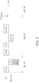
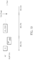
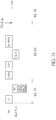
- FIGs. 10-14 illustrate additional dynamic operation mode switch scenarios.
- the AP MLD e.g., one of Wi-Fi MLDs 102 and 104 shown in FIG.
- the non-AP MLD (e.g., the other of Wi-Fi MLDs 102 and 104 shown in FIG. 1 ) sends a trigger frame TF being an MU-RTS frame
- the non-AP MLD (e.g., the other of Wi-Fi MLDs 102 and 104 shown in FIG. 1 ) may respond with a response frame RF being a CTS frame after receiving the MU-RTS frame.
- the AP MLD e.g., one of Wi-Fi MLDs 102 and 104 shown in FIG. 1
- the non-AP MLD (e.g., the other of Wi-Fi MLDs 102 and 104 shown in FIG. 1 ) may respond with a response frame RF being a buffer status report (BSR) frame after receiving the BSRP frame.
- BSR buffer status report
- the operation mode change signaling design employed by the RTS/CTS mechanism may also be employed by the MU-RTS/CTS mechanism and the BSRP/BSR mechanism. Since a person skilled in the art can readily understand details of the dynamic operation mode switch examples shown in FIGs. 10-14 after reading above paragraphs directed to FIGs. 2-4 and 7-8 , similar description is omitted here for brevity. It should be noted that one Wi-Fi MLD of the present invention may support one or more of the dynamic operation mode switch scenarios mentioned above.
Landscapes
- Engineering & Computer Science (AREA)
- Computer Networks & Wireless Communication (AREA)
- Signal Processing (AREA)
- Quality & Reliability (AREA)
- Mobile Radio Communication Systems (AREA)
Abstract
Description
- This application claims the benefit of
U.S. provisional application No. 63/048,733 - The present invention relates to wireless communications, and more particularly, to a wireless fidelity (Wi-Fi) multi-link device (MLD) with dynamic operation mode switch and an associated method.
- In a Wi-Fi multi-link operation, there exists several links between two Wi-Fi MLDs, including one access point (AP) and one non-AP station (STA), that occupy different radio-frequency (RF) bands. One Wi-Fi MLD can perform channel access (e.g., enhanced distributed channel access (EDCA)) on multiple wireless links independently. Specifically, these wireless links can operate independently to increase the overall throughput and/or to improve the connection stability. For example, one Wi-Fi MLD may have one spatial stream specified on one wireless link. If a wireless link can use more resources to transmit or receive during a specific period, the performance of the wireless link can be improved. Thus, there is a need for an innovative design which is capable of dynamically changing operation mode parameter(s) of a Wi-Fi MLD.
- One of the objectives of the claimed invention is to provide a wireless fidelity (Wi-Fi) multi-link device (MLD) with dynamic operation mode switch and an associated method. Wi-Fi MLDs and a wireless communication method employed by a Wi-Fi MLD according to the invention are defined in the independent claims. The dependent claims define preferred embodiments thereof.
- According to a first aspect of the present invention, an exemplary wireless fidelity (Wi-Fi) multi-link device (MLD) is disclosed. The exemplary MLD includes a transmit (TX) circuit, a receive (RX) circuit, and a control circuit. The control circuit is arranged to control the RX circuit to receive a first frame under an operation mode parameter with a first setting, control the TX circuit to transmit a second frame responsive to the first frame under the operation mode parameter with the first setting, and after the second frame is transmitted, control the RX circuit to receive at least one physical layer protocol data unit (PPDU) under the operation mode parameter with a second setting, wherein the second setting is different from the first setting.
- According to a second aspect of the present invention, an exemplary wireless fidelity (Wi-Fi) multi-link device (MLD) is disclosed. The MLD includes a transmit (TX) circuit, a receive (RX) circuit, and a control circuit. The control circuit is arranged to control the TX circuit to transmit a first frame under an operation mode parameter with a first setting, control the RX circuit to receive a second frame responsive to the first frame under the operation mode parameter with the first setting, and after the second frame is received, control the TX circuit to transmit at least one physical layer protocol data unit (PPDU) under the operation mode parameter with a second setting, wherein the second setting is different from the first setting.
- According to a third aspect of the present invention, an exemplary wireless communication method employed by a wireless fidelity (Wi-Fi) multi-link device (MLD) is disclosed. The exemplary wireless communication method includes: controlling a receive (RX) circuit to receive a first frame under a first operation mode parameter with a first setting; controlling a transmit (TX) circuit to transmit a second frame responsive to the first frame under the first operation mode parameter with the first setting; after the second frame is transmitted, controlling the RX circuit to receive at least one physical layer protocol data unit (PPDU) under the first operation mode parameter with a second setting, wherein the second setting is different from the first setting; controlling the TX circuit to transmit a third frame under a second operation mode parameter with a third setting; controlling the RX circuit to receive a fourth frame responsive to the third frame under the second operation mode parameter with the third setting; and after the fourth frame is received, controlling the TX circuit to transmit at least one PPDU under the second operation mode parameter with a fourth setting, wherein the fourth setting is different from the third setting.
- These and other objectives of the present invention will no doubt become obvious to those of ordinary skill in the art after reading the following detailed description of the preferred embodiment that is illustrated in the various figures and drawings.
-
-
FIG. 1 is a diagram illustrating a wireless fidelity (Wi-Fi) communication system according to an embodiment of the present invention. -
FIG. 2 is a diagram illustrating a first dynamic operation mode switch scenario according to an embodiment of the present invention. -
FIG. 3 is a diagram illustrating a second dynamic operation mode switch scenario according to an embodiment of the present invention. -
FIG. 4 is a diagram illustrating a third dynamic operation mode switch scenario according to an embodiment of the present invention. -
FIG. 5 is a diagram illustrating a fourth dynamic operation mode switch scenario according to an embodiment of the present invention. -
FIG. 6 is a diagram illustrating a fifth dynamic operation mode switch scenario according to an embodiment of the present invention. -
FIG. 7 is a diagram illustrating a sixth dynamic operation mode switch scenario according to an embodiment of the present invention. -
FIG. 8 is a diagram illustrating a seventh dynamic operation mode switch scenario according to an embodiment of the present invention. -
FIG. 9 is a diagram illustrating additional signaling provided by a channel quality indicator feedback according to an embodiment of the present invention. -
FIG. 10 is a diagram illustrating an alternative design implemented on the basis of the dynamic operation mode switch scenario shown inFIG. 2 . -
FIG. 11 is a diagram illustrating an alternative design implemented on the basis of the dynamic operation mode switch scenario shown inFIG. 3 . -
FIG. 12 is a diagram illustrating an alternative design implemented on the basis of the dynamic operation mode switch scenario shown inFIG. 4 . -
FIG. 13 is a diagram illustrating an alternative design implemented on the basis of the dynamic operation mode switch scenario shown inFIG. 7 . -
FIG. 14 is a diagram illustrating an alternative design implemented on the basis of the dynamic operation mode switch scenario shown inFIG. 8 . - Certain terms are used throughout the following description and claims, which refer to particular components. As one skilled in the art will appreciate, electronic equipment manufacturers may refer to a component by different names. This document does not intend to distinguish between components that differ in name but not in function. In the following description and in the claims, the terms "include" and "comprise" are used in an open-ended fashion, and thus should be interpreted to mean "include, but not limited to ...". Also, the term "couple" is intended to mean either an indirect or direct electrical connection. Accordingly, if one device is coupled to another device, that connection may be through a direct electrical connection, or through an indirect electrical connection via other devices and connections.
-
FIG. 1 is a diagram illustrating a wireless fidelity (Wi-Fi) communication system according to an embodiment of the present invention. The Wi-Fi communication system 100 has a plurality of Wi-Fi multi-link devices (MLDs) 102 and 104, including an access point (AP) and a non-AP station (STA). For example, the Wi-Fi MLD 104 may be an AP, and the Wi-Fi MLD 102 may be a non-AP STA. For brevity and simplicity, only two Wi-Fi MLDs are shown inFIG. 1 . In practice, the Wi-Fi communication system 100 is allowed to have more than two Wi-Fi MLDs, including an AP and more than one non-AP STA in the same basic service set (BSS). By way of example, but not limitation, both of Wi-Fi MLDs - As shown in
FIG. 1 , the Wi-Fi MLD 102 includes aprocessor 112, amemory 114, acontrol circuit 116, a receive (RX)circuit 118, a transmit (TX)circuit 120, andmultiple antennas 122. Thememory 114 is arranged to store a program code. Theprocessor 112 is arranged to load and execute the program code to manage the Wi-Fi MLD 102. Thecontrol circuit 116 is arranged to control wireless communications with the Wi-Fi MLD 104. Considering a case where the Wi-Fi MLD 102 is a non-AP STA and the Wi-Fi MLD 104 is an AP, thecontrol circuit 116 controls theTX circuit 120 to deal with uplink (UL) traffic between AP and non-AP STA, and controls theRX circuit 118 to deal with downlink (DL) traffic between AP and non-AP STA. Due to inherent characteristics of Wi-Fi MLD 102, theTX circuit 120 includes multiple TX chains, and theRX circuit 118 includes multiple RX chains. In this embodiment, the Wi-Fi MLD 102 is equipped with dynamic operation mode switch functionality. - Regarding DL traffic between AP and non-AP STA, the
control circuit 116 is arranged to control theRX circuit 118 to receive a first frame under an operation mode parameter with a first setting (e.g., default setting), control theTX circuit 120 to transmit a second frame responsive to the first frame under the operation mode parameter with the first setting, and after the second frame is transmitted, control theRX circuit 118 to receive at least one DL physical layer protocol data unit (PPDU) under the operation mode parameter with a second setting (e.g., maximum setting or non-default setting) during a remaining period of a transmission opportunity (TXOP), wherein the second setting is different from the first setting. In addition, thecontrol circuit 116 is further arranged to control theRX circuit 118 to resume the operation mode parameter with the first setting (e.g., default setting) at an end of the TXOP. - In one exemplary mode switch design, the first frame may be a request to send (RTS) frame, and the second frame may be a clear to send (CTS) frame responsive to the RTS frame, where the RTS frame does not carry any indication of operation mode parameter change, and the CTS frame may or may not carry indication of operation mode parameter change that specifies the use of the second setting. When the CTS frame does not carry any indication of operation mode parameter change, the CTS frame may act as indication of using the maximum setting for the operation mode parameter (i.e., second setting = maximum setting).
- In another exemplary mode switch design, the first frame may be an RTS frame, and the second frame may be a CTS frame responsive to the RTS frame, where the CTS frame does not carry any indication of operation mode parameter change, and the RTS frame may or may not carry indication of operation mode parameter change that specifies the use of the second setting. When the RTS frame does not carry any indication of operation mode parameter change, the RTS frame may act as indication of using the maximum setting for the operation mode parameter (i.e., second setting = maximum setting).
- In yet another exemplary mode switch design, the first frame may be an inquiry frame transmitted after RTS/CTS handshaking is done, and the second frame may be a response frame responsive to the inquiry frame, where the response frame is particularly designed to carry indication of operation mode parameter change that specifies the use of the second setting (e.g., maximum setting or non-default setting).
- Regarding UL traffic between AP and non-AP STA, the
control circuit 116 is arranged to control theTX circuit 120 to transmit a first frame under an operation mode parameter with a first setting (e.g., default setting), control theRX circuit 118 to receive a second frame responsive to the first frame under the operation mode parameter with the first setting, and after the second frame is received, control theTX circuit 120 to transmit at least one UL PPDU under the operation mode parameter with a second setting (e.g., maximum setting or non-default setting) during a remaining period of a TXOP, wherein the second setting is different from the first setting. In addition, thecontrol circuit 116 is further arranged to control theTX circuit 120 to resume the operation mode parameter with the first setting (e.g., default setting) at an end of the TXOP. - The Wi-
Fi MLD 102 can have different operation modes on each link established between Wi-Fi MLDs - For better understanding of technical features of the proposed dynamic operation mode switch scheme, several examples are provided as below.
-
FIG. 2 is a diagram illustrating a first dynamic operation mode switch scenario according to an embodiment of the present invention. In this embodiment, the Wi-Fi MLD 104 may be an AP, the Wi-Fi MLD 102 may be a non-AP STA, and the Wi-Fi MLD 102 on a link may set a default receive (RX) NSS = 1 and a maximum RX NSS = 4. On each link, the Wi-Fi MLD 102 operates under a default mode listening to the channel. Thecontrol circuit 116 controls theRX circuit 118 to receive an RTS frame from Wi-Fi MLD (which is an AP) 104, where the RTS frame is sent to initialize a TXOP. After theRX circuit 118 receives the RTS frame on a link, thecontrol circuit 116 controls theTX circuit 120 to respond with a CTS frame on the same link, where the RTS/CTS mechanism claims the TXOP for frame exchange. The RTS frame is received based on a default operation mode parameter (e.g., RX NSS = 1). In this embodiment, the CTS frame carries indication IND of operation mode parameter change that specifies the use of RX NSS = 2. In other words, the Wi-Fi MLD 102 will control theRX circuit 118 to switch another RX chain to the link for enhancing the RX NSS capability. After the CTS frame is transmitted by theTX circuit 120, thecontrol circuit 116 controls theRX circuit 118 to operate under a changed operation mode parameter (e.g., RX NSS = 2) and other unchanged parameters, and receive one or more DL PPDUs on the link during a remaining period of the TXOP. Hence, during the remaining period of the TXOP, DL PPDU(s) can be received by RX NSS = 2. At an end of the TXOP, thecontrol circuit 116 controls theRX circuit 118 to resume the default operation mode parameter (e.g., RX NSS = 1) on the link. It should be noted that, if the CTS frame does not carry any indication of operation mode parameter change, the maximum setting (e.g., RX NSS = 4) is inferred from such a CTS frame. -
FIG. 3 is a diagram illustrating a second dynamic operation mode switch scenario according to an embodiment of the present invention. In this embodiment, the Wi-Fi MLD 104 may be an AP, the Wi-Fi MLD 102 may be a non-AP STA, and the Wi-Fi MLD 102 on a link may set a default RX NSS = 1 and a maximum RX NSS = 4. On each link, the Wi-Fi MLD 102 operates under a default mode listening to the channel. Thecontrol circuit 116 controls theRX circuit 118 to receive an RTS frame from Wi-Fi MLD (which is an AP) 104, where the RTS frame is sent to initialize a TXOP. After theRX circuit 118 receives the RTS frame on a link, thecontrol circuit 116 controls theTX circuit 120 to respond with a CTS frame on the same link, where the RTS/CTS mechanism claims a TXOP for frame exchange. After the CTS frame is transmitted by theTX circuit 120, theRX circuit 118 receives an inquiry frame sent from Wi-Fi MLD (which is an AP) 104, where the inquiry frame is used to make an inquiry about possible operation mode change for the following period of the TXOP on the link. TheTX circuit 120 sends back a response frame after the inquiry frame is received by theRX circuit 118. The RTS frame and the inquiry frame are both received based on a default operation mode parameter (e.g., RX NSS = 1). In this embodiment, the response frame carries indication IND of operation mode parameter change that specifies the use of RX NSS = 4. In other words, the Wi-Fi MLD 102 will control theRX circuit 118 to switch other RX chains to the link for achieving its maximum RX NSS capability. After the response frame is transmitted by theTX circuit 120, thecontrol circuit 116 controls theRX circuit 118 to operate under a changed operation mode parameter (e.g., RX NSS = 4) and other unchanged parameters, and receive one or more DL PPDUs on the link during a remaining period of the TXOP. Hence, during the remaining period of the TXOP, DL PPDU(s) can be received by RX NSS = 4. At an end of the TXOP, thecontrol circuit 116 controls theRX circuit 118 to resume the default operation mode parameter (e.g., RX NSS = 1) on the link. -
FIG. 4 is a diagram illustrating a third dynamic operation mode switch scenario according to an embodiment of the present invention. In this embodiment, the Wi-Fi MLD 104 may be an AP, the Wi-Fi MLD 102 may be a non-AP STA, and the Wi-Fi MLD 102 on a link may set a default bandwidth (BW) = 80 MHz and a maximum BW = 160 MHz. On each link, the Wi-Fi MLD 102 operates under a default mode listening to the channel. Thecontrol circuit 116 controls theRX circuit 118 to receive an RTS frame from Wi-Fi MLD (which is an AP) 104, where the RTS frame is sent to initialize a TXOP, and also carries indication IND of operation mode parameter change that specifies the use of BW = 160 MHz. After the RTS frame is received by theRX circuit 118, thecontrol circuit 116 controls theTX circuit 120 to respond with a CTS frame on the same link, where the RTS/CTS mechanism claims a TXOP for frame exchange, and the CTS frame also carries indication IND' about accepting the request of operation mode parameter change or rejecting the request of operation mode parameter change. The RTS frame is received based on the default operation mode parameter (e.g., BW = 80 MHz). If thecontrol circuit 116 accepts the request of operation mode parameter change, thecontrol circuit 116 controls theRX circuit 118 to change the BW to 160 MHz on the link. In other words, thecontrol circuit 116 controls theRX circuit 118 to operate under a changed operation mode parameter (e.g., BW = 160 MHz) and other unchanged parameters, and receive one or more DL PPDUs on the link during a remaining period of the TXOP. Hence, during the remaining period of the TXOP, DL PPDU(s) can be received by BW = 160 MHz. At an end of the TXOP, thecontrol circuit 116 controls theRX circuit 118 to resume the default operation mode parameter (e.g., BW = 80 MHz) on the link. -
FIG. 5 is a diagram illustrating a fourth dynamic operation mode switch scenario according to an embodiment of the present invention. In this embodiment, the Wi-Fi MLD 104 may be an AP, the Wi-Fi MLD 102 may be a non-AP STA, and the Wi-Fi MLD 102 on a link may set a default transmit (TX) NSS = 1 and a maximum TX NSS = 4. On each link, the Wi-Fi MLD 102 operates under a default mode listening to the channel. Thecontrol circuit 116 controls theTX circuit 120 to transmit an RTS frame on a link to initialize a TXOP. The RTS frame is transmitted based on the default operation mode parameter (e.g., TX NSS = 1). In this embodiment, the RTS frame carries indication IND of operation mode parameter change that specifies the use of TX NSS = 2. In other words, the Wi-Fi MLD 102 will control theTX circuit 120 to switch another TX chain to the link for enhancing the TX NSS capability. TheRX circuit 118 receives a CTS frame responsive to the RTS frame from Wi-Fi MLD (which is an AP) 104 on the same link, where the RTS/CTS mechanism claims a TXOP for frame exchange. After the CTS frame is received by theRX circuit 118, thecontrol circuit 116 controls theTX circuit 120 to operate under a changed operation mode parameter (e.g., TX NSS = 2) and other unchanged parameters, and transmit one or more UL PPDUs on the link during a remaining period of the TXOP. Hence, during the remaining period of the TXOP, UL PPDU(s) can be transmitted by TX NSS = 2. At an end of the TXOP, thecontrol circuit 116 controls theTX circuit 120 to resume the default operation mode parameter (e.g., TX NSS = 1) on the link. -
FIG. 6 is a diagram illustrating a fifth dynamic operation mode switch scenario according to an embodiment of the present invention. In this embodiment, the Wi-Fi MLD 104 may be an AP, the Wi-Fi MLD 102 may be a non-AP STA, and the Wi-Fi MLD 102 on a link may set a default TX NSS = 1 and a maximum TX NSS = 4. On each link, the Wi-Fi MLD 102 operates under a default mode listening to the channel. Thecontrol circuit 116 controls theTX circuit 120 to transmit an RTS frame on a link, and then controls theRX circuit 118 to receive a CTS frame responsive to the RTS frame from Wi-Fi MLD (which is an AP) 104 on the same link, where the RTS/CTS mechanism claims a TXOP for frame exchange. After the CTS frame is received by theRX circuit 118, thecontrol circuit 116 controls theTX circuit 120 to transmit an announcement frame that is used to announce operation mode change for the following period of the TXOP on the link. In this embodiment, the announcement frame carries indication IND of operation mode parameter change that specifies the use of TX NSS = 2. In other words, the Wi-Fi MLD 102 will control theTX circuit 120 to switch another TX chain to the link for enhancing the TX NSS capability. The RTS frame and the announcement frame are both transmitted based on the default operation mode parameter (e.g., TX NSS = 1). After theRX circuit 118 receives a response frame responsive to the announcement frame from the Wi-Fi MLD (which is an AP) 104, thecontrol circuit 116 controls theTX circuit 120 to operate under a changed operation mode parameter (e.g., TX NSS = 2) and other unchanged parameters, and transmit one or more UL PPDUs on the link during a remaining period of the TXOP. Hence, during the remaining period of the TXOP, UL PPDU(s) can be transmitted by TX NSS = 2. At an end of the TXOP, thecontrol circuit 116 controls theTX circuit 120 to resume the default operation mode parameter (e.g., TX NSS = 1) on the link. - As mentioned above, the CTS frame/response frame is capable of carrying indication of operation mode change. In some embodiments of the present invention, more signaling can be exchanged during the initialization of the period so that efficiency during that period can be further improved. For example, since RX chain switch may require additional sounding to ensure the RX quality, the CTS frame/response frame may further carry a sounding request. For another example, the CTS frame/response frame may further carry an RX chain bitmap that is used for indicating which antennas are used on a certain link for an RX operation and is also used for allowing a sender (which transmits the RTS frame/inquiry frame) to use suitable beamforming parameters derived from previous sounding.
-
FIG. 7 is a diagram illustrating a sixth dynamic operation mode switch scenario according to an embodiment of the present invention. In this embodiment, the Wi-Fi MLD 104 may be an AP, the Wi-Fi MLD 102 may be a non-AP STA, and the Wi-Fi MLD 102 on a link may set a default RX NSS = 1 and a maximum RX NSS = 4. On each link, the Wi-Fi MLD 102 operates under a default mode listening to the channel. After theRX circuit 118 receives an RTS frame from Wi-Fi MLD (which is an AP) 104 on a link, thecontrol circuit 116 controls theTX circuit 120 to respond with a CTS frame on the same link, where the RTS/CTS mechanism claims a TXOP for frame exchange. The RTS frame is received based on the default operation mode parameter (e.g., RX NSS = 1). In this embodiment, the CTS frame carries indication IND of operation mode parameter change that specifies the use of RX NSS = 2, and also carries a sounding request SR. After the CTS frame is received by the Wi-Fi MLD (which is an AP) 104, the Wi-Fi MLD 104 accepts the sounding request SR, and then initiates a sounding process by sending a null data packet announcement (NDPA) frame and a null data packet (NDP) frame, and the Wi-Fi MLD (which is a non-AP STA) 102 replies with a channel quality indicator (CQI) feedback (FB) during the sounding process. After the CTS frame is transmitted by theTX circuit 120, thecontrol circuit 116 controls theRX circuit 118 to operate under a changed operation mode parameter (e.g., RX NSS = 2) and other unchanged parameters, and receive one or more DL PPDUs on the link during a remaining period of the TXOP. Hence, during the remaining period of the TXOP, DL PPDU(s) can be received by RX NSS = 2. At an end of the TXOP, thecontrol circuit 116 controls theRX circuit 118 to resume the default operation mode parameter (e.g., RX NSS = 1) on the link. -
FIG. 8 is a diagram illustrating a seventh dynamic operation mode switch scenario according to an embodiment of the present invention. In this embodiment, the Wi-Fi MLD 104 may be an AP, the Wi-Fi MLD 102 may be a non-AP STA, and the Wi-Fi MLD 102 on a link may set a default RX NSS = 1 and a maximum RX NSS = 4. On each link, the Wi-Fi MLD 102 operates under a default mode listening to the channel. After theRX circuit 118 receives an RTS frame from Wi-Fi MLD (which is an AP) 104 on a link, thecontrol circuit 116 controls theTX circuit 120 to respond with a CTS frame on the same link, where the RTS/CTS mechanism claims a TXOP for frame exchange. The RTS frame is received based on the default operation mode parameter (e.g., RX NSS = 1). In this embodiment, the CTS frame carries indication IND of operation mode parameter change that specifies the use of RX NSS = 2, and also carries an RX chain bitmap BMP. After the CTS frame received by the Wi-Fi MLD (which is an AP) 104, the Wi-Fi MLD 104 refers to the RX chain bitmap BMP to decide to do sounding, and initiates a sounding process by sending an NDPA frame and an NDP frame, where the RX chain bitmap BMP indicates the RX NSS employed by Wi-Fi MLD (which is a no-AP STA) 102. The Wi-Fi MLD 102 replies with a CQI FB during the sounding process, where the CQI FB is based on the RX bitmap BMP carried in the CTS frame. After the CTS frame is transmitted by theTX circuit 120, thecontrol circuit 116 controls theRX circuit 118 to operate under a changed operation mode parameter (e.g., RX NSS = 2) and other unchanged parameters, and receive one or more DL PPDUs on the link during a remaining period of the TXOP. Hence, during the remaining period of the TXOP, DL PPDU(s) can be received by RX NSS = 2. At an end of the TXOP, thecontrol circuit 116 controls theRX circuit 118 to resume the default operation mode parameter (e.g., RX NSS = 1) on the link. -
FIG. 9 is a diagram illustrating additional signaling provided by a channel quality indicator feedback according to an embodiment of the present invention. For any sounding process (NDPA+NDP+CQI FB) applied on any link of a multi-link operation (MLO), CQI FB can also carry the RX chain bitmap BMP. In this way, sounding overhead reduction can be achieved if the same RX chains are used on some links in the future. - In above embodiments, an AP MLD uses an RTS frame as an initial Control frame of a frame exchange sequence. However, these are for illustrative purposes only, and are not meant to be limitations of the present invention. In some embodiments of the present invention, the initial Control frame of the frame exchange sequence that is initiated by the AP MLD may be a trigger frame, such as a multi-user request to send (MU-RTS) frame or a buffer status report poll (BSRP) frame.
FIGs. 10-14 illustrate additional dynamic operation mode switch scenarios. In a case where the AP MLD (e.g., one of Wi-Fi MLDs FIG. 1 ) sends a trigger frame TF being an MU-RTS frame, the non-AP MLD (e.g., the other of Wi-Fi MLDs FIG. 1 ) may respond with a response frame RF being a CTS frame after receiving the MU-RTS frame. In another case where the AP MLD (e.g., one of Wi-Fi MLDs FIG. 1 ) sends a trigger frame TF being a BSRP frame, the non-AP MLD (e.g., the other of Wi-Fi MLDs FIG. 1 ) may respond with a response frame RF being a buffer status report (BSR) frame after receiving the BSRP frame. The operation mode change signaling design employed by the RTS/CTS mechanism may also be employed by the MU-RTS/CTS mechanism and the BSRP/BSR mechanism. Since a person skilled in the art can readily understand details of the dynamic operation mode switch examples shown inFIGs. 10-14 after reading above paragraphs directed toFIGs. 2-4 and7-8 , similar description is omitted here for brevity. It should be noted that one Wi-Fi MLD of the present invention may support one or more of the dynamic operation mode switch scenarios mentioned above. - Those skilled in the art will readily observe that numerous modifications and alterations of the device and method may be made while retaining the teachings of the invention. Accordingly, the above disclosure should be construed as limited only by the metes and bounds of the appended claims.
Claims (15)
- A wireless fidelity, in the following also referred to as Wi-Fi multi-link device, in the following also referred to as MLD, comprising:a transmit, in the following also referred to as TX, circuit (120);a receive, in the following also referred to as RX, circuit (118); anda control circuit (116), arranged to control the RX circuit (118) to receive a first frame under an operation mode parameter with a first setting, control the TX circuit (120) to transmit a second frame responsive to the first frame under the operation mode parameter with the first setting, and after the second frame is transmitted, control the RX circuit (118) to receive at least one physical layer protocol data unit, in the following also referred to as PPDU, under the operation mode parameter with a second setting, wherein the second setting is different from the first setting.
- The Wi-Fi MLD of claim 1, wherein the first frame is one of a request to send, in the following also referred to as RTS, frame, a multi-user request to send, in the following also referred to as MU-RTS, frame and a buffer status report poll, in the following also referred to as BSRP, frame, and the second frame is one of a clear to send, in the following also referred to as CTS, frame and a buffer status report, in the following also referred to as BSR, frame.
- The Wi-Fi MLD of claim 2, wherein one of the first frame and the second frame carries indication of operation mode parameter change that specifies the use of the second setting or
wherein none of the first frame and the second frame carries indication of operation mode parameter change that specifies the use of the second setting. - The Wi-Fi MLD of claim 2 or 3, wherein the second frame further carries a sounding request; and/or
wherein the second frame further carries an RX chain bitmap. - The Wi-Fi MLD of any one of claims 1 to 4, wherein before the first frame is received, the control circuit (116) is further arranged to control the RX circuit (118) to receive a third frame under the operation mode parameter with the first setting, and control the TX circuit (120) to transmit a fourth frame responsive to the third frame under the operation mode parameter with the first setting; and
wherein the first frame is an inquiry frame, and the second frame is a response frame that is responsive to the inquiry frame and carries indication of operation mode parameter change that specifies the use of the second setting; and
wherein the third frame is one of a RTS frame, a MU-RTS frame and a BSRP frame, and the fourth frame is one of a CTS frame and a BSR frame. - The Wi-Fi MLD of claim 5, wherein the response frame further carries a sounding request; and/or
wherein the response frame further carries an RX chain bitmap. - The Wi-Fi MLD of any one of claims 1 to 6, wherein the control circuit is further arranged to control the TX circuit (120) to transmit a CQI feedback frame during a sounding process, and the CQI feedback frame carries an RX chain bitmap.
- The Wi-Fi MLD of any one of claims 1 to 7, wherein said at least one PPDU is received during a transmission opportunity, in the following also referred to as TXOP, and the control circuit is further arranged to control the RX circuit (118) to resume the operation mode parameter with the first setting at an end of the TXOP.
- A wireless fidelity, in the following also referred to as Wi-Fi, multi-link device, in the following also referred to as MLD, comprising:a transmit, in the following also referred to as TX, circuit (120);a receive, in the following also referred to as RX, circuit (118); anda control circuit (116), arranged to control the TX circuit (120) to transmit a first frame under an operation mode parameter with a first setting, control the RX circuit (118) to receive a second frame responsive to the first frame under the operation mode parameter with the first setting, and after the second frame is received, control the TX circuit (1 20) to transmit at least one physical layer protocol data unit, in the following also referred to as PPDU, under the operation mode parameter with a second setting, wherein the second setting is different from the first setting.
- The Wi-Fi MLD of claim 9, wherein the first frame is a request to send, in the following also referred to as RTS, frame, and the second frame is a clear to send, in the following also referred to as CTS, frame.
- The Wi-Fi MLD of claim 10, wherein the RTS frame carries indication of operation mode parameter change that specifies the use of the second setting; or
wherein the RTS frame does not carry indication of operation mode parameter change that specifies the use of the second setting. - The Wi-Fi MLD of any one of claims 9 to 11, wherein before the first frame is transmitted, the control circuit (116) is further arranged to control the TX circuit (120) to transmit a RTS frame under the operation mode parameter with the first setting, and control the RX circuit (118) to receive a CTS frame responsive to the RTS frame under the operation mode parameter with the first setting; the first frame is an announcement frame carrying indication of operation mode parameter change that specifies the use of the second setting, and the second frame is a response frame responsive to the announcement frame.
- The Wi-Fi MLD of any one of claims 9 to 12, wherein said at least one PPDU is transmitted during a transmission opportunity, in the following also referred to as TXOP, and the control circuit is further arranged to control the TX circuit to resume the operation mode parameter with the first setting at an end of the TXOP.
- The Wi-Fi MLD of any one of claims 1 to 13, wherein the operation mode parameter is a number of spatial streams, a bandwidth, a decoding capability, a maximum media access control protocol data unit, in the following also referred to as MPDU, length, a maximum aggregate media access control service data unit, in the following also referred to as A-MSDU, length, or a maximum aggregate media access control protocol data unit, in the following also referred to as A-MPDU, length exponent.
- A wireless communication method employed by a wireless fidelity, in the following also referred to as Wi-Fi, multi-link device, in the following also referred to as MLD, comprising:controlling a receive, in the following also referred to as RX, circuit to receive a first frame under a first operation mode parameter with a first setting;controlling a transmit, in the following also referred to as TX, circuit to transmit a second frame responsive to the first frame under the first operation mode parameter with the first setting;after the second frame is transmitted, controlling the RX circuit to receive at least one physical layer protocol data unit, in the following also referred to as PPDU, under the first operation mode parameter with a second setting, wherein the second setting is different from the first setting;controlling the TX circuit to transmit a third frame under a second operation mode parameter with a third setting;controlling the RX circuit to receive a fourth frame responsive to the third frame under the second operation mode parameter with the third setting; andafter the fourth frame is received, controlling the TX circuit to transmit at least one PPDU under the second operation mode parameter with a fourth setting, wherein the fourth setting is different from the third setting.
Applications Claiming Priority (2)
| Application Number | Priority Date | Filing Date | Title |
|---|---|---|---|
| US202063048733P | 2020-07-07 | 2020-07-07 | |
| US17/367,437 US11658768B2 (en) | 2020-07-07 | 2021-07-05 | Wireless fidelity multi-link device with dynamic operation mode switch and associated method |
Publications (2)
| Publication Number | Publication Date |
|---|---|
| EP3937584A1 true EP3937584A1 (en) | 2022-01-12 |
| EP3937584B1 EP3937584B1 (en) | 2024-06-26 |
Family
ID=76829352
Family Applications (1)
| Application Number | Title | Priority Date | Filing Date |
|---|---|---|---|
| EP21184045.9A Active EP3937584B1 (en) | 2020-07-07 | 2021-07-06 | Wireless fidelity multi-link device with dynamic operation mode switch and associated method |
Country Status (3)
| Country | Link |
|---|---|
| US (2) | US11658768B2 (en) |
| EP (1) | EP3937584B1 (en) |
| TW (1) | TWI772093B (en) |
Families Citing this family (2)
| Publication number | Priority date | Publication date | Assignee | Title |
|---|---|---|---|---|
| US12425172B2 (en) * | 2021-09-22 | 2025-09-23 | Samsung Electronics Co., Ltd. | CQI enhancement for multi-link operation |
| US20240298369A1 (en) * | 2023-03-02 | 2024-09-05 | Samsung Electronics Co., Ltd. | Radio reconfiguration in multi-link device |
Citations (4)
| Publication number | Priority date | Publication date | Assignee | Title |
|---|---|---|---|---|
| US20100080173A1 (en) * | 2008-09-26 | 2010-04-01 | Kabushiki Kaisha Toshiba | Apparatus and method for wireless communication |
| WO2010107165A1 (en) * | 2009-03-16 | 2010-09-23 | Lg Electronics Inc. | Method of allocating radio resource |
| US20190364555A1 (en) * | 2018-06-15 | 2019-11-28 | Po-Kai Huang | Extreme high throughput physical layer data rate |
| EP3914017A1 (en) * | 2020-05-13 | 2021-11-24 | MediaTek Singapore Pte. Ltd. | Extreme-high-throughput enhanced subchannel selective transmission operation in wireless communications |
Family Cites Families (6)
| Publication number | Priority date | Publication date | Assignee | Title |
|---|---|---|---|---|
| US10263750B2 (en) | 2014-12-23 | 2019-04-16 | Intel Corporation | Cross indication of queue size in a reverse direction protocol |
| EP3968724A4 (en) * | 2019-05-09 | 2023-06-28 | Hyundai Motor Company | Frame transmission method and device using multiple random backoff operation in broadband wireless communication network |
| EP3997955B1 (en) * | 2019-07-10 | 2025-03-12 | ZTE Corporation | Multi-link communications of a wireless network |
| US11395265B2 (en) * | 2019-10-28 | 2022-07-19 | Intel Corporation | Multi-link acknowledgments in multi-link devices |
| US11641660B2 (en) * | 2019-11-12 | 2023-05-02 | Nxp Usa, Inc. | Multi-antenna processing in multi-link wireless communication systems |
| US11706128B2 (en) * | 2020-01-04 | 2023-07-18 | Nxp Usa, Inc. | Method and apparatus for multi-link data transmission |
-
2021
- 2021-07-05 US US17/367,437 patent/US11658768B2/en active Active
- 2021-07-06 EP EP21184045.9A patent/EP3937584B1/en active Active
- 2021-07-06 TW TW110124759A patent/TWI772093B/en active
-
2023
- 2023-04-19 US US18/136,342 patent/US12567924B2/en active Active
Patent Citations (4)
| Publication number | Priority date | Publication date | Assignee | Title |
|---|---|---|---|---|
| US20100080173A1 (en) * | 2008-09-26 | 2010-04-01 | Kabushiki Kaisha Toshiba | Apparatus and method for wireless communication |
| WO2010107165A1 (en) * | 2009-03-16 | 2010-09-23 | Lg Electronics Inc. | Method of allocating radio resource |
| US20190364555A1 (en) * | 2018-06-15 | 2019-11-28 | Po-Kai Huang | Extreme high throughput physical layer data rate |
| EP3914017A1 (en) * | 2020-05-13 | 2021-11-24 | MediaTek Singapore Pte. Ltd. | Extreme-high-throughput enhanced subchannel selective transmission operation in wireless communications |
Non-Patent Citations (1)
| Title |
|---|
| YONGHO SEOK (MEDIATEK): "Multi-link Spatial Multiplexing", vol. 802.11 EHT; 802.11be, 2 July 2020 (2020-07-02), pages 1 - 14, XP068169740, Retrieved from the Internet <URL:https://mentor.ieee.org/802.11/dcn/20/11-20-0883-00-00be-multi-link-spatial-multiplexing.pptx> [retrieved on 20200702] * |
Also Published As
| Publication number | Publication date |
|---|---|
| EP3937584B1 (en) | 2024-06-26 |
| TWI772093B (en) | 2022-07-21 |
| US11658768B2 (en) | 2023-05-23 |
| US20220014305A1 (en) | 2022-01-13 |
| US20230261782A1 (en) | 2023-08-17 |
| TW202203701A (en) | 2022-01-16 |
| US12567924B2 (en) | 2026-03-03 |
Similar Documents
| Publication | Publication Date | Title |
|---|---|---|
| US11641660B2 (en) | Multi-antenna processing in multi-link wireless communication systems | |
| US12126448B2 (en) | Wireless communication method supporting multi-user cascading transmission and wireless communication terminal using same | |
| US9793966B2 (en) | Link adaptation method and apparatus in wireless LAN system | |
| US12317192B2 (en) | Power save for multi-user (MU) operation | |
| EP3577787A1 (en) | Fast beam refinement phase for periodic beamforming training | |
| US12567924B2 (en) | Wireless fidelity multi-link device with dynamic operation mode switch and associated method | |
| EP4298747B1 (en) | Cqi enhancement for multi-link operation | |
| WO2022014192A1 (en) | Terminal, and communication method | |
| US20250267708A1 (en) | Multi-ap transmission scheme selection | |
| US12262431B2 (en) | Wi-Fi multi-link device for indicating capabilities of affiliated stations for different enabled link combinations during association and related capability indication method | |
| CN118102423A (en) | Information indication method and device | |
| WO2021090718A1 (en) | Communication device and information processing method | |
| CN113904700B (en) | Wi-Fi multi-link equipment and wireless communication method adopted by same | |
| CN117042045A (en) | Data transmission method and device | |
| CN114900211A (en) | Communication apparatus and communication method | |
| WO2022054628A1 (en) | Communication device | |
| US12615677B2 (en) | Communication apparatus, communication control method, communication method, and computer-readable storage medium | |
| US20240284496A1 (en) | Low latency frame notification | |
| US20240064808A1 (en) | Method and apparatus for assisting wireless communication device with switch back operation for early switching back to listening operation on enhanced multi-link single radio links | |
| US10849080B1 (en) | Trigger MPDU for client-selectable transmit power | |
| WO2026086717A1 (en) | Wireless communication method for dealing with unavailable window adjustment and related wireless communication device |
Legal Events
| Date | Code | Title | Description |
|---|---|---|---|
| PUAI | Public reference made under article 153(3) epc to a published international application that has entered the european phase |
Free format text: ORIGINAL CODE: 0009012 |
|
| STAA | Information on the status of an ep patent application or granted ep patent |
Free format text: STATUS: THE APPLICATION HAS BEEN PUBLISHED |
|
| AK | Designated contracting states |
Kind code of ref document: A1 Designated state(s): AL AT BE BG CH CY CZ DE DK EE ES FI FR GB GR HR HU IE IS IT LI LT LU LV MC MK MT NL NO PL PT RO RS SE SI SK SM TR |
|
| B565 | Issuance of search results under rule 164(2) epc |
Effective date: 20211202 |
|
| STAA | Information on the status of an ep patent application or granted ep patent |
Free format text: STATUS: REQUEST FOR EXAMINATION WAS MADE |
|
| 17P | Request for examination filed |
Effective date: 20220707 |
|
| RBV | Designated contracting states (corrected) |
Designated state(s): AL AT BE BG CH CY CZ DE DK EE ES FI FR GB GR HR HU IE IS IT LI LT LU LV MC MK MT NL NO PL PT RO RS SE SI SK SM TR |
|
| STAA | Information on the status of an ep patent application or granted ep patent |
Free format text: STATUS: EXAMINATION IS IN PROGRESS |
|
| 17Q | First examination report despatched |
Effective date: 20221215 |
|
| P01 | Opt-out of the competence of the unified patent court (upc) registered |
Effective date: 20230607 |
|
| GRAP | Despatch of communication of intention to grant a patent |
Free format text: ORIGINAL CODE: EPIDOSNIGR1 |
|
| STAA | Information on the status of an ep patent application or granted ep patent |
Free format text: STATUS: GRANT OF PATENT IS INTENDED |
|
| RIC1 | Information provided on ipc code assigned before grant |
Ipc: H04B 7/0413 20170101ALN20240111BHEP Ipc: H04W 74/0816 20240101ALN20240111BHEP Ipc: H04W 74/00 20090101AFI20240111BHEP |
|
| INTG | Intention to grant announced |
Effective date: 20240122 |
|
| RIN1 | Information on inventor provided before grant (corrected) |
Inventor name: SEOK, YONGHO Inventor name: HSIEH, HUNG-TAO Inventor name: CHANG, CHENG-YI Inventor name: HSU, CHIEN-FANG |
|
| GRAS | Grant fee paid |
Free format text: ORIGINAL CODE: EPIDOSNIGR3 |
|
| GRAA | (expected) grant |
Free format text: ORIGINAL CODE: 0009210 |
|
| STAA | Information on the status of an ep patent application or granted ep patent |
Free format text: STATUS: THE PATENT HAS BEEN GRANTED |
|
| AK | Designated contracting states |
Kind code of ref document: B1 Designated state(s): AL AT BE BG CH CY CZ DE DK EE ES FI FR GB GR HR HU IE IS IT LI LT LU LV MC MK MT NL NO PL PT RO RS SE SI SK SM TR |
|
| RAP3 | Party data changed (applicant data changed or rights of an application transferred) |
Owner name: MEDIATEK INC. |
|
| REG | Reference to a national code |
Ref country code: GB Ref legal event code: FG4D |
|
| REG | Reference to a national code |
Ref country code: CH Ref legal event code: EP |
|
| REG | Reference to a national code |
Ref country code: DE Ref legal event code: R096 Ref document number: 602021014725 Country of ref document: DE |
|
| PG25 | Lapsed in a contracting state [announced via postgrant information from national office to epo] |
Ref country code: BG Free format text: LAPSE BECAUSE OF FAILURE TO SUBMIT A TRANSLATION OF THE DESCRIPTION OR TO PAY THE FEE WITHIN THE PRESCRIBED TIME-LIMIT Effective date: 20240626 |
|
| PG25 | Lapsed in a contracting state [announced via postgrant information from national office to epo] |
Ref country code: FI Free format text: LAPSE BECAUSE OF FAILURE TO SUBMIT A TRANSLATION OF THE DESCRIPTION OR TO PAY THE FEE WITHIN THE PRESCRIBED TIME-LIMIT Effective date: 20240626 Ref country code: HR Free format text: LAPSE BECAUSE OF FAILURE TO SUBMIT A TRANSLATION OF THE DESCRIPTION OR TO PAY THE FEE WITHIN THE PRESCRIBED TIME-LIMIT Effective date: 20240626 |
|
| REG | Reference to a national code |
Ref country code: LT Ref legal event code: MG9D |
|
| PG25 | Lapsed in a contracting state [announced via postgrant information from national office to epo] |
Ref country code: GR Free format text: LAPSE BECAUSE OF FAILURE TO SUBMIT A TRANSLATION OF THE DESCRIPTION OR TO PAY THE FEE WITHIN THE PRESCRIBED TIME-LIMIT Effective date: 20240927 |
|
| PG25 | Lapsed in a contracting state [announced via postgrant information from national office to epo] |
Ref country code: LV Free format text: LAPSE BECAUSE OF FAILURE TO SUBMIT A TRANSLATION OF THE DESCRIPTION OR TO PAY THE FEE WITHIN THE PRESCRIBED TIME-LIMIT Effective date: 20240626 |
|
| REG | Reference to a national code |
Ref country code: NL Ref legal event code: MP Effective date: 20240626 |
|
| PG25 | Lapsed in a contracting state [announced via postgrant information from national office to epo] |
Ref country code: NO Free format text: LAPSE BECAUSE OF FAILURE TO SUBMIT A TRANSLATION OF THE DESCRIPTION OR TO PAY THE FEE WITHIN THE PRESCRIBED TIME-LIMIT Effective date: 20240926 Ref country code: LV Free format text: LAPSE BECAUSE OF FAILURE TO SUBMIT A TRANSLATION OF THE DESCRIPTION OR TO PAY THE FEE WITHIN THE PRESCRIBED TIME-LIMIT Effective date: 20240626 Ref country code: HR Free format text: LAPSE BECAUSE OF FAILURE TO SUBMIT A TRANSLATION OF THE DESCRIPTION OR TO PAY THE FEE WITHIN THE PRESCRIBED TIME-LIMIT Effective date: 20240626 Ref country code: GR Free format text: LAPSE BECAUSE OF FAILURE TO SUBMIT A TRANSLATION OF THE DESCRIPTION OR TO PAY THE FEE WITHIN THE PRESCRIBED TIME-LIMIT Effective date: 20240927 Ref country code: FI Free format text: LAPSE BECAUSE OF FAILURE TO SUBMIT A TRANSLATION OF THE DESCRIPTION OR TO PAY THE FEE WITHIN THE PRESCRIBED TIME-LIMIT Effective date: 20240626 Ref country code: BG Free format text: LAPSE BECAUSE OF FAILURE TO SUBMIT A TRANSLATION OF THE DESCRIPTION OR TO PAY THE FEE WITHIN THE PRESCRIBED TIME-LIMIT Effective date: 20240626 Ref country code: RS Free format text: LAPSE BECAUSE OF FAILURE TO SUBMIT A TRANSLATION OF THE DESCRIPTION OR TO PAY THE FEE WITHIN THE PRESCRIBED TIME-LIMIT Effective date: 20240926 |
|
| PG25 | Lapsed in a contracting state [announced via postgrant information from national office to epo] |
Ref country code: NL Free format text: LAPSE BECAUSE OF FAILURE TO SUBMIT A TRANSLATION OF THE DESCRIPTION OR TO PAY THE FEE WITHIN THE PRESCRIBED TIME-LIMIT Effective date: 20240626 |
|
| REG | Reference to a national code |
Ref country code: AT Ref legal event code: MK05 Ref document number: 1698741 Country of ref document: AT Kind code of ref document: T Effective date: 20240626 |
|
| PG25 | Lapsed in a contracting state [announced via postgrant information from national office to epo] |
Ref country code: NL Free format text: LAPSE BECAUSE OF FAILURE TO SUBMIT A TRANSLATION OF THE DESCRIPTION OR TO PAY THE FEE WITHIN THE PRESCRIBED TIME-LIMIT Effective date: 20240626 |
|
| PG25 | Lapsed in a contracting state [announced via postgrant information from national office to epo] |
Ref country code: PT Free format text: LAPSE BECAUSE OF FAILURE TO SUBMIT A TRANSLATION OF THE DESCRIPTION OR TO PAY THE FEE WITHIN THE PRESCRIBED TIME-LIMIT Effective date: 20241028 |
|
| PG25 | Lapsed in a contracting state [announced via postgrant information from national office to epo] |
Ref country code: PT Free format text: LAPSE BECAUSE OF FAILURE TO SUBMIT A TRANSLATION OF THE DESCRIPTION OR TO PAY THE FEE WITHIN THE PRESCRIBED TIME-LIMIT Effective date: 20241028 |
|
| PG25 | Lapsed in a contracting state [announced via postgrant information from national office to epo] |
Ref country code: PL Free format text: LAPSE BECAUSE OF FAILURE TO SUBMIT A TRANSLATION OF THE DESCRIPTION OR TO PAY THE FEE WITHIN THE PRESCRIBED TIME-LIMIT Effective date: 20240626 |
|
| PG25 | Lapsed in a contracting state [announced via postgrant information from national office to epo] |
Ref country code: EE Free format text: LAPSE BECAUSE OF FAILURE TO SUBMIT A TRANSLATION OF THE DESCRIPTION OR TO PAY THE FEE WITHIN THE PRESCRIBED TIME-LIMIT Effective date: 20240626 |
|
| PG25 | Lapsed in a contracting state [announced via postgrant information from national office to epo] |
Ref country code: AT Free format text: LAPSE BECAUSE OF FAILURE TO SUBMIT A TRANSLATION OF THE DESCRIPTION OR TO PAY THE FEE WITHIN THE PRESCRIBED TIME-LIMIT Effective date: 20240626 Ref country code: IS Free format text: LAPSE BECAUSE OF FAILURE TO SUBMIT A TRANSLATION OF THE DESCRIPTION OR TO PAY THE FEE WITHIN THE PRESCRIBED TIME-LIMIT Effective date: 20241026 |
|
| PG25 | Lapsed in a contracting state [announced via postgrant information from national office to epo] |
Ref country code: CZ Free format text: LAPSE BECAUSE OF FAILURE TO SUBMIT A TRANSLATION OF THE DESCRIPTION OR TO PAY THE FEE WITHIN THE PRESCRIBED TIME-LIMIT Effective date: 20240626 |
|
| PG25 | Lapsed in a contracting state [announced via postgrant information from national office to epo] |
Ref country code: RO Free format text: LAPSE BECAUSE OF FAILURE TO SUBMIT A TRANSLATION OF THE DESCRIPTION OR TO PAY THE FEE WITHIN THE PRESCRIBED TIME-LIMIT Effective date: 20240626 Ref country code: SK Free format text: LAPSE BECAUSE OF FAILURE TO SUBMIT A TRANSLATION OF THE DESCRIPTION OR TO PAY THE FEE WITHIN THE PRESCRIBED TIME-LIMIT Effective date: 20240626 |
|
| PG25 | Lapsed in a contracting state [announced via postgrant information from national office to epo] |
Ref country code: ES Free format text: LAPSE BECAUSE OF FAILURE TO SUBMIT A TRANSLATION OF THE DESCRIPTION OR TO PAY THE FEE WITHIN THE PRESCRIBED TIME-LIMIT Effective date: 20240626 Ref country code: SM Free format text: LAPSE BECAUSE OF FAILURE TO SUBMIT A TRANSLATION OF THE DESCRIPTION OR TO PAY THE FEE WITHIN THE PRESCRIBED TIME-LIMIT Effective date: 20240626 |
|
| PG25 | Lapsed in a contracting state [announced via postgrant information from national office to epo] |
Ref country code: SM Free format text: LAPSE BECAUSE OF FAILURE TO SUBMIT A TRANSLATION OF THE DESCRIPTION OR TO PAY THE FEE WITHIN THE PRESCRIBED TIME-LIMIT Effective date: 20240626 Ref country code: SK Free format text: LAPSE BECAUSE OF FAILURE TO SUBMIT A TRANSLATION OF THE DESCRIPTION OR TO PAY THE FEE WITHIN THE PRESCRIBED TIME-LIMIT Effective date: 20240626 Ref country code: RO Free format text: LAPSE BECAUSE OF FAILURE TO SUBMIT A TRANSLATION OF THE DESCRIPTION OR TO PAY THE FEE WITHIN THE PRESCRIBED TIME-LIMIT Effective date: 20240626 Ref country code: PL Free format text: LAPSE BECAUSE OF FAILURE TO SUBMIT A TRANSLATION OF THE DESCRIPTION OR TO PAY THE FEE WITHIN THE PRESCRIBED TIME-LIMIT Effective date: 20240626 Ref country code: IS Free format text: LAPSE BECAUSE OF FAILURE TO SUBMIT A TRANSLATION OF THE DESCRIPTION OR TO PAY THE FEE WITHIN THE PRESCRIBED TIME-LIMIT Effective date: 20241026 Ref country code: ES Free format text: LAPSE BECAUSE OF FAILURE TO SUBMIT A TRANSLATION OF THE DESCRIPTION OR TO PAY THE FEE WITHIN THE PRESCRIBED TIME-LIMIT Effective date: 20240626 Ref country code: EE Free format text: LAPSE BECAUSE OF FAILURE TO SUBMIT A TRANSLATION OF THE DESCRIPTION OR TO PAY THE FEE WITHIN THE PRESCRIBED TIME-LIMIT Effective date: 20240626 Ref country code: CZ Free format text: LAPSE BECAUSE OF FAILURE TO SUBMIT A TRANSLATION OF THE DESCRIPTION OR TO PAY THE FEE WITHIN THE PRESCRIBED TIME-LIMIT Effective date: 20240626 Ref country code: AT Free format text: LAPSE BECAUSE OF FAILURE TO SUBMIT A TRANSLATION OF THE DESCRIPTION OR TO PAY THE FEE WITHIN THE PRESCRIBED TIME-LIMIT Effective date: 20240626 |
|
| PG25 | Lapsed in a contracting state [announced via postgrant information from national office to epo] |
Ref country code: IT Free format text: LAPSE BECAUSE OF FAILURE TO SUBMIT A TRANSLATION OF THE DESCRIPTION OR TO PAY THE FEE WITHIN THE PRESCRIBED TIME-LIMIT Effective date: 20240626 |
|
| REG | Reference to a national code |
Ref country code: CH Ref legal event code: PL |
|
| PG25 | Lapsed in a contracting state [announced via postgrant information from national office to epo] |
Ref country code: LU Free format text: LAPSE BECAUSE OF NON-PAYMENT OF DUE FEES Effective date: 20240706 |
|
| PG25 | Lapsed in a contracting state [announced via postgrant information from national office to epo] |
Ref country code: MC Free format text: LAPSE BECAUSE OF FAILURE TO SUBMIT A TRANSLATION OF THE DESCRIPTION OR TO PAY THE FEE WITHIN THE PRESCRIBED TIME-LIMIT Effective date: 20240626 |
|
| REG | Reference to a national code |
Ref country code: DE Ref legal event code: R097 Ref document number: 602021014725 Country of ref document: DE |
|
| PG25 | Lapsed in a contracting state [announced via postgrant information from national office to epo] |
Ref country code: MC Free format text: LAPSE BECAUSE OF FAILURE TO SUBMIT A TRANSLATION OF THE DESCRIPTION OR TO PAY THE FEE WITHIN THE PRESCRIBED TIME-LIMIT Effective date: 20240626 Ref country code: LU Free format text: LAPSE BECAUSE OF NON-PAYMENT OF DUE FEES Effective date: 20240706 |
|
| PG25 | Lapsed in a contracting state [announced via postgrant information from national office to epo] |
Ref country code: DK Free format text: LAPSE BECAUSE OF FAILURE TO SUBMIT A TRANSLATION OF THE DESCRIPTION OR TO PAY THE FEE WITHIN THE PRESCRIBED TIME-LIMIT Effective date: 20240626 |
|
| PG25 | Lapsed in a contracting state [announced via postgrant information from national office to epo] |
Ref country code: CH Free format text: LAPSE BECAUSE OF NON-PAYMENT OF DUE FEES Effective date: 20240731 Ref country code: BE Free format text: LAPSE BECAUSE OF NON-PAYMENT OF DUE FEES Effective date: 20240731 |
|
| PLBE | No opposition filed within time limit |
Free format text: ORIGINAL CODE: 0009261 |
|
| STAA | Information on the status of an ep patent application or granted ep patent |
Free format text: STATUS: NO OPPOSITION FILED WITHIN TIME LIMIT |
|
| RAP4 | Party data changed (patent owner data changed or rights of a patent transferred) |
Owner name: MEDIATEK INC. |
|
| 26N | No opposition filed |
Effective date: 20250327 |
|
| REG | Reference to a national code |
Ref country code: BE Ref legal event code: MM Effective date: 20240731 |
|
| PGFP | Annual fee paid to national office [announced via postgrant information from national office to epo] |
Ref country code: GB Payment date: 20250515 Year of fee payment: 5 |
|
| PG25 | Lapsed in a contracting state [announced via postgrant information from national office to epo] |
Ref country code: FR Free format text: LAPSE BECAUSE OF NON-PAYMENT OF DUE FEES Effective date: 20240826 |
|
| PG25 | Lapsed in a contracting state [announced via postgrant information from national office to epo] |
Ref country code: IE Free format text: LAPSE BECAUSE OF NON-PAYMENT OF DUE FEES Effective date: 20240706 |
|
| PG25 | Lapsed in a contracting state [announced via postgrant information from national office to epo] |
Ref country code: SE Free format text: LAPSE BECAUSE OF FAILURE TO SUBMIT A TRANSLATION OF THE DESCRIPTION OR TO PAY THE FEE WITHIN THE PRESCRIBED TIME-LIMIT Effective date: 20240626 |
|
| PGFP | Annual fee paid to national office [announced via postgrant information from national office to epo] |
Ref country code: DE Payment date: 20250514 Year of fee payment: 5 |
|
| PG25 | Lapsed in a contracting state [announced via postgrant information from national office to epo] |
Ref country code: CY Free format text: LAPSE BECAUSE OF FAILURE TO SUBMIT A TRANSLATION OF THE DESCRIPTION OR TO PAY THE FEE WITHIN THE PRESCRIBED TIME-LIMIT; INVALID AB INITIO Effective date: 20210706 |
|
| PG25 | Lapsed in a contracting state [announced via postgrant information from national office to epo] |
Ref country code: HU Free format text: LAPSE BECAUSE OF FAILURE TO SUBMIT A TRANSLATION OF THE DESCRIPTION OR TO PAY THE FEE WITHIN THE PRESCRIBED TIME-LIMIT; INVALID AB INITIO Effective date: 20210706 |