EP3937494A1 - Method for decoding image and apparatus using same - Google Patents
Method for decoding image and apparatus using same Download PDFInfo
- Publication number
- EP3937494A1 EP3937494A1 EP21188128.9A EP21188128A EP3937494A1 EP 3937494 A1 EP3937494 A1 EP 3937494A1 EP 21188128 A EP21188128 A EP 21188128A EP 3937494 A1 EP3937494 A1 EP 3937494A1
- Authority
- EP
- European Patent Office
- Prior art keywords
- layer
- tier
- profile
- vps
- information
- Prior art date
- Legal status (The legal status is an assumption and is not a legal conclusion. Google has not performed a legal analysis and makes no representation as to the accuracy of the status listed.)
- Withdrawn
Links
- 238000000034 method Methods 0.000 title claims abstract description 84
- 239000010410 layer Substances 0.000 description 429
- 239000011229 interlayer Substances 0.000 description 75
- 230000002123 temporal effect Effects 0.000 description 57
- 230000033001 locomotion Effects 0.000 description 17
- 230000011664 signaling Effects 0.000 description 16
- 238000010586 diagram Methods 0.000 description 8
- 208000037170 Delayed Emergence from Anesthesia Diseases 0.000 description 7
- 239000000470 constituent Substances 0.000 description 7
- 230000005540 biological transmission Effects 0.000 description 6
- 230000008569 process Effects 0.000 description 6
- 230000006835 compression Effects 0.000 description 5
- 238000007906 compression Methods 0.000 description 5
- 238000013139 quantization Methods 0.000 description 4
- 108091000069 Cystinyl Aminopeptidase Proteins 0.000 description 3
- 102100020872 Leucyl-cystinyl aminopeptidase Human genes 0.000 description 3
- 238000005192 partition Methods 0.000 description 3
- 230000003044 adaptive effect Effects 0.000 description 2
- 238000005070 sampling Methods 0.000 description 2
- FMYKJLXRRQTBOR-UBFHEZILSA-N (2s)-2-acetamido-4-methyl-n-[4-methyl-1-oxo-1-[[(2s)-1-oxohexan-2-yl]amino]pentan-2-yl]pentanamide Chemical group CCCC[C@@H](C=O)NC(=O)C(CC(C)C)NC(=O)[C@H](CC(C)C)NC(C)=O FMYKJLXRRQTBOR-UBFHEZILSA-N 0.000 description 1
- 241000206607 Porphyra umbilicalis Species 0.000 description 1
- 230000008859 change Effects 0.000 description 1
- 230000000694 effects Effects 0.000 description 1
- 238000012986 modification Methods 0.000 description 1
- 230000004048 modification Effects 0.000 description 1
- 229940075930 picrate Drugs 0.000 description 1
- OXNIZHLAWKMVMX-UHFFFAOYSA-M picrate anion Chemical compound [O-]C1=C([N+]([O-])=O)C=C([N+]([O-])=O)C=C1[N+]([O-])=O OXNIZHLAWKMVMX-UHFFFAOYSA-M 0.000 description 1
- 230000007480 spreading Effects 0.000 description 1
- 230000000153 supplemental effect Effects 0.000 description 1
Images
Classifications
-
- H—ELECTRICITY
- H04—ELECTRIC COMMUNICATION TECHNIQUE
- H04N—PICTORIAL COMMUNICATION, e.g. TELEVISION
- H04N19/00—Methods or arrangements for coding, decoding, compressing or decompressing digital video signals
- H04N19/30—Methods or arrangements for coding, decoding, compressing or decompressing digital video signals using hierarchical techniques, e.g. scalability
-
- H—ELECTRICITY
- H04—ELECTRIC COMMUNICATION TECHNIQUE
- H04N—PICTORIAL COMMUNICATION, e.g. TELEVISION
- H04N19/00—Methods or arrangements for coding, decoding, compressing or decompressing digital video signals
- H04N19/10—Methods or arrangements for coding, decoding, compressing or decompressing digital video signals using adaptive coding
- H04N19/134—Methods or arrangements for coding, decoding, compressing or decompressing digital video signals using adaptive coding characterised by the element, parameter or criterion affecting or controlling the adaptive coding
- H04N19/157—Assigned coding mode, i.e. the coding mode being predefined or preselected to be further used for selection of another element or parameter
- H04N19/159—Prediction type, e.g. intra-frame, inter-frame or bidirectional frame prediction
-
- G—PHYSICS
- G10—MUSICAL INSTRUMENTS; ACOUSTICS
- G10L—SPEECH ANALYSIS TECHNIQUES OR SPEECH SYNTHESIS; SPEECH RECOGNITION; SPEECH OR VOICE PROCESSING TECHNIQUES; SPEECH OR AUDIO CODING OR DECODING
- G10L15/00—Speech recognition
- G10L15/04—Segmentation; Word boundary detection
-
- G—PHYSICS
- G10—MUSICAL INSTRUMENTS; ACOUSTICS
- G10L—SPEECH ANALYSIS TECHNIQUES OR SPEECH SYNTHESIS; SPEECH RECOGNITION; SPEECH OR VOICE PROCESSING TECHNIQUES; SPEECH OR AUDIO CODING OR DECODING
- G10L15/00—Speech recognition
- G10L15/22—Procedures used during a speech recognition process, e.g. man-machine dialogue
-
- G—PHYSICS
- G10—MUSICAL INSTRUMENTS; ACOUSTICS
- G10L—SPEECH ANALYSIS TECHNIQUES OR SPEECH SYNTHESIS; SPEECH RECOGNITION; SPEECH OR VOICE PROCESSING TECHNIQUES; SPEECH OR AUDIO CODING OR DECODING
- G10L15/00—Speech recognition
- G10L15/26—Speech to text systems
-
- G—PHYSICS
- G10—MUSICAL INSTRUMENTS; ACOUSTICS
- G10L—SPEECH ANALYSIS TECHNIQUES OR SPEECH SYNTHESIS; SPEECH RECOGNITION; SPEECH OR VOICE PROCESSING TECHNIQUES; SPEECH OR AUDIO CODING OR DECODING
- G10L17/00—Speaker identification or verification techniques
-
- G—PHYSICS
- G10—MUSICAL INSTRUMENTS; ACOUSTICS
- G10L—SPEECH ANALYSIS TECHNIQUES OR SPEECH SYNTHESIS; SPEECH RECOGNITION; SPEECH OR VOICE PROCESSING TECHNIQUES; SPEECH OR AUDIO CODING OR DECODING
- G10L25/00—Speech or voice analysis techniques not restricted to a single one of groups G10L15/00 - G10L21/00
- G10L25/78—Detection of presence or absence of voice signals
-
- H—ELECTRICITY
- H04—ELECTRIC COMMUNICATION TECHNIQUE
- H04N—PICTORIAL COMMUNICATION, e.g. TELEVISION
- H04N19/00—Methods or arrangements for coding, decoding, compressing or decompressing digital video signals
- H04N19/10—Methods or arrangements for coding, decoding, compressing or decompressing digital video signals using adaptive coding
- H04N19/169—Methods or arrangements for coding, decoding, compressing or decompressing digital video signals using adaptive coding characterised by the coding unit, i.e. the structural portion or semantic portion of the video signal being the object or the subject of the adaptive coding
- H04N19/17—Methods or arrangements for coding, decoding, compressing or decompressing digital video signals using adaptive coding characterised by the coding unit, i.e. the structural portion or semantic portion of the video signal being the object or the subject of the adaptive coding the unit being an image region, e.g. an object
- H04N19/172—Methods or arrangements for coding, decoding, compressing or decompressing digital video signals using adaptive coding characterised by the coding unit, i.e. the structural portion or semantic portion of the video signal being the object or the subject of the adaptive coding the unit being an image region, e.g. an object the region being a picture, frame or field
-
- H—ELECTRICITY
- H04—ELECTRIC COMMUNICATION TECHNIQUE
- H04N—PICTORIAL COMMUNICATION, e.g. TELEVISION
- H04N19/00—Methods or arrangements for coding, decoding, compressing or decompressing digital video signals
- H04N19/10—Methods or arrangements for coding, decoding, compressing or decompressing digital video signals using adaptive coding
- H04N19/169—Methods or arrangements for coding, decoding, compressing or decompressing digital video signals using adaptive coding characterised by the coding unit, i.e. the structural portion or semantic portion of the video signal being the object or the subject of the adaptive coding
- H04N19/184—Methods or arrangements for coding, decoding, compressing or decompressing digital video signals using adaptive coding characterised by the coding unit, i.e. the structural portion or semantic portion of the video signal being the object or the subject of the adaptive coding the unit being bits, e.g. of the compressed video stream
-
- H—ELECTRICITY
- H04—ELECTRIC COMMUNICATION TECHNIQUE
- H04N—PICTORIAL COMMUNICATION, e.g. TELEVISION
- H04N19/00—Methods or arrangements for coding, decoding, compressing or decompressing digital video signals
- H04N19/10—Methods or arrangements for coding, decoding, compressing or decompressing digital video signals using adaptive coding
- H04N19/169—Methods or arrangements for coding, decoding, compressing or decompressing digital video signals using adaptive coding characterised by the coding unit, i.e. the structural portion or semantic portion of the video signal being the object or the subject of the adaptive coding
- H04N19/187—Methods or arrangements for coding, decoding, compressing or decompressing digital video signals using adaptive coding characterised by the coding unit, i.e. the structural portion or semantic portion of the video signal being the object or the subject of the adaptive coding the unit being a scalable video layer
-
- H—ELECTRICITY
- H04—ELECTRIC COMMUNICATION TECHNIQUE
- H04N—PICTORIAL COMMUNICATION, e.g. TELEVISION
- H04N19/00—Methods or arrangements for coding, decoding, compressing or decompressing digital video signals
- H04N19/70—Methods or arrangements for coding, decoding, compressing or decompressing digital video signals characterised by syntax aspects related to video coding, e.g. related to compression standards
-
- G—PHYSICS
- G10—MUSICAL INSTRUMENTS; ACOUSTICS
- G10L—SPEECH ANALYSIS TECHNIQUES OR SPEECH SYNTHESIS; SPEECH RECOGNITION; SPEECH OR VOICE PROCESSING TECHNIQUES; SPEECH OR AUDIO CODING OR DECODING
- G10L15/00—Speech recognition
- G10L15/005—Language recognition
-
- G—PHYSICS
- G10—MUSICAL INSTRUMENTS; ACOUSTICS
- G10L—SPEECH ANALYSIS TECHNIQUES OR SPEECH SYNTHESIS; SPEECH RECOGNITION; SPEECH OR VOICE PROCESSING TECHNIQUES; SPEECH OR AUDIO CODING OR DECODING
- G10L15/00—Speech recognition
- G10L15/01—Assessment or evaluation of speech recognition systems
-
- G—PHYSICS
- G10—MUSICAL INSTRUMENTS; ACOUSTICS
- G10L—SPEECH ANALYSIS TECHNIQUES OR SPEECH SYNTHESIS; SPEECH RECOGNITION; SPEECH OR VOICE PROCESSING TECHNIQUES; SPEECH OR AUDIO CODING OR DECODING
- G10L15/00—Speech recognition
- G10L15/06—Creation of reference templates; Training of speech recognition systems, e.g. adaptation to the characteristics of the speaker's voice
- G10L15/063—Training
-
- G—PHYSICS
- G10—MUSICAL INSTRUMENTS; ACOUSTICS
- G10L—SPEECH ANALYSIS TECHNIQUES OR SPEECH SYNTHESIS; SPEECH RECOGNITION; SPEECH OR VOICE PROCESSING TECHNIQUES; SPEECH OR AUDIO CODING OR DECODING
- G10L15/00—Speech recognition
- G10L15/08—Speech classification or search
- G10L15/14—Speech classification or search using statistical models, e.g. Hidden Markov Models [HMMs]
- G10L15/142—Hidden Markov Models [HMMs]
-
- G—PHYSICS
- G10—MUSICAL INSTRUMENTS; ACOUSTICS
- G10L—SPEECH ANALYSIS TECHNIQUES OR SPEECH SYNTHESIS; SPEECH RECOGNITION; SPEECH OR VOICE PROCESSING TECHNIQUES; SPEECH OR AUDIO CODING OR DECODING
- G10L15/00—Speech recognition
- G10L15/08—Speech classification or search
- G10L15/16—Speech classification or search using artificial neural networks
-
- G—PHYSICS
- G10—MUSICAL INSTRUMENTS; ACOUSTICS
- G10L—SPEECH ANALYSIS TECHNIQUES OR SPEECH SYNTHESIS; SPEECH RECOGNITION; SPEECH OR VOICE PROCESSING TECHNIQUES; SPEECH OR AUDIO CODING OR DECODING
- G10L15/00—Speech recognition
- G10L15/28—Constructional details of speech recognition systems
- G10L15/32—Multiple recognisers used in sequence or in parallel; Score combination systems therefor, e.g. voting systems
-
- G—PHYSICS
- G10—MUSICAL INSTRUMENTS; ACOUSTICS
- G10L—SPEECH ANALYSIS TECHNIQUES OR SPEECH SYNTHESIS; SPEECH RECOGNITION; SPEECH OR VOICE PROCESSING TECHNIQUES; SPEECH OR AUDIO CODING OR DECODING
- G10L25/00—Speech or voice analysis techniques not restricted to a single one of groups G10L15/00 - G10L21/00
- G10L25/48—Speech or voice analysis techniques not restricted to a single one of groups G10L15/00 - G10L21/00 specially adapted for particular use
- G10L25/51—Speech or voice analysis techniques not restricted to a single one of groups G10L15/00 - G10L21/00 specially adapted for particular use for comparison or discrimination
Definitions
- the present invention relates to video encoding and decoding, and more particularly, to methods and apparatuses for encoding and decoding a video supporting a plurality of layers in a bitstream.
- an inter prediction technique of predicting pixel values included in a current picture from temporally previous and/or subsequent pictures of the current picture an intra prediction technique of predicting pixel values included in a current picture using pixel information in the current picture, or an entropy encoding technique of assigning a short code to a symbol with a high appearance frequency and assigning a long code to a symbol with a low appearance frequency.
- Video compression technology may include a technique of providing a constant network bandwidth in restricted operating environments of hardware without considering variable network environments.
- new compression techniques are required, wherein a scalable video encoding/decoding method may be employed.
- An aspect of the present invention is to provide a method of signaling layer information contained in a video encoded bitstream of a multilayer structure including a temporal layer, an interlayer prediction method and a method of obtaining a target output layer.
- Another aspect of the present invention is to provide a method of accessing layer information specified in a video parameter set (VPS) in a bitstream for session negotiations without an entropy decoder and an apparatus using the same.
- VPN video parameter set
- Still another aspect of the present invention is to provide a method of identifying a number of active interlayer reference pictures needed for decoding a current picture for utilization in interlayer prediction, a method of obtaining a target output layer and an apparatus using the same.
- An aspect of the present invention provides a method of decoding a video supporting a plurality of layers, the method including receiving information on a reference layer used for decoding a current picture for interlayer prediction; deriving a number of active reference layer pictures used for decoding the current picture based on the information on the reference layer; and performing interlayer prediction based on the number of active reference layer pictures.
- All slices of the current picture may have the same number of active reference layer pictures.
- the number of active reference layer pictures may be derived to be 0.
- the number of active reference layer pictures may be derived to be 0.
- the number of active reference layer pictures may be derived to be 0.
- the number of active reference layer pictures may be derived based on a variable indicating a number of direct reference layers of the current layer, maximum temporal sub-layer information on each layer, maximum allowed value of temporal sub-layer allowing inter-layer prediction in each layer and the temporal identifier of the current picture.
- a number of pictures in a reference layer having maximum temporal sub-layer information greater than or equal to the temporal identifier of the current picture and maximum temporal sub-layer information allowing interlayer prediction greater than the temporal identifier of the current picture, among direct reference layer pictures for the current picture, may be used as the number of active reference layer pictures for decoding the current picture.
- the number of active reference layer pictures may be derived to be 0.
- the number of active reference layer pictures may be derived to be 1.
- the number of active reference layer pictures may be derived to be 1 if a number of reference layer pictures available for decoding the current picture is greater than 0, and the number of active reference layer pictures may be derived to be 0 if the number of reference layer pictures available for decoding the current picture is 0.
- the number of active reference layer pictures may be derived to be 1.
- the number of active reference layer pictures may be derived to be a value specified by the number information.
- a method of signaling layer information present in a video encoded bitstream of a multilayer structure including a temporal layer, an interlayer prediction method, and a method of obtaining a target output layer.
- MEM Media Aware Network Equipment
- a method of accurately identifying a number of active interlayer reference pictures needed for decoding a current picture for utilization in interlayer prediction a method of obtaining a target output layer and an apparatus using the same.
- first, second, etc. may be used to describe various elements, these elements should not be limited by these terms. These terms are used only to distinguish one element from another element. For example, a first element may be named a second element without departing from the scope of the present invention. Likewise, a second element may be named a first element.
- each component includes individual components that are arranged for convenience of description, in which at least two components may be combined into a single component or a single component may be divided into a plurality of components to perform functions. It is to be noted that embodiments in which some components are integrated into one combined component and/or a component is divided into multiple separate components are included in the scope of the present invention without departing from the essence of the present invention.
- constituent elements are not essential to perform the substantial functions in the invention and may be optional constituent elements for merely improving performance.
- the present invention may be embodied by including only constituent elements essential to implement the spirit of the invention other than constituent elements used for merely improving performance.
- a structure including only the essential constituent elements other than optional constituents used for merely improving performance also belongs to the scope of the present invention.
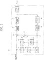
- FIG. 1 is a block diagram illustrating a configuration of a video encoding apparatus according to an embodiment.
- a scalable video encoding/decoding method or apparatus may be realized by extension of a general video encoding/decoding method or apparatus that does not provide scalability, and the block diagram of FIG. 1 illustrates an example of a video encoding apparatus which may form a basis for a scalable video encoding apparatus.
- the video encoding apparatus 100 includes a motion estimation module 111, a motion compensation module 112, an intra prediction module 120, a switch 115, a subtractor 125, a transform module 130, a quantization module140, an entropy encoding module 150, an dequantization module160, an inverse transform module 170, an adder 175, a filter module 180, and a reference picture buffer 190.
- the video encoding apparatus 100 may encode an input picture images in an intra mode or an inter mode and output a bitstream.
- Intra prediction means an intra-picture prediction
- inter prediction means an inter-picture prediction.
- the switch 115 is shifted to 'intra,' and in the inter mode, the switch 115 is shifted to 'inter.'
- the video encoding apparatus 100 may generate a prediction block for an input block of the input picture and then encode a difference between the input block and the prediction block.
- the intra prediction module 120 may perform spatial prediction by using a pixel value of a pre-encoded block around a current block to generate a prediction block.
- the motion estimation module 111 may obtain a region which is most matched with the input block in the reference picture stored in the reference picture buffer 190 during a motion estimation process to derive a motion vector.
- the motion compensation module 112 may perform motion compensation using the motion vector and the reference picture stored in the reference picture buffer 190, thereby generating the prediction block.
- the subtractor 125 may generate a residual block based on the difference between the input block and the generated prediction block.
- the transform module 130 may transform the residual block to output a transform coefficient.
- the quantization module 140 may quantize the transform coefficient according to a quantization parameter to output a quantized coefficient.
- the entropy encoding module 150 may entropy-encode a symbol according to probability distribution based on values derived by the quantization module 140 or an encoding parameter value derived in encoding, thereby outputting a bitstream.
- Entropy encoding is a method of receiving symbols having different values and representing the symbols as a decodable binary sequence or string while removing statistical redundancy.
- a symbol means a syntax element as an encoding/decoding target, a coding parameter, a value of a residual signal, or the like.
- a coding parameter which is a parameter necessary for encoding and decoding, may include information encoded by the encoding apparatus and transferred to the decoding apparatus, such as a syntax element, and information to be inferred during an encoding or decoding process and means information necessary for encoding and decoding a picture.
- the coding parameter may include, for example, values or statistics of an intra/inter prediction mode, a movement/motion vector, a reference picture index, a coding block pattern, presence and absence of a residual signal, a transform coefficient, a quantized transform coefficient, a block size and block partition information.
- a residual signal may denote a difference between an original signal and a prediction signal, a transformed signal of the difference between the original signal and the prediction signal, or a transformed and quantized signal of the difference between the original signal and the prediction signal.
- the residual signal may be referred to as a residual block in a block unit.
- entropy encoding When entropy encoding is applied, a symbol having a high probability is allocated a small number of bits and a symbol having a low probability is allocated a large number of bits in representation of symbols, thereby reducing a size of bit strings for symbols to be encoded. Accordingly, entropy encoding may enhance compression performance of video encoding.
- encoding methods such as exponential Golomb, context-adaptive variable length coding (CAVLC) and context-adaptive binary arithmetic coding (CABAC) may be used.
- a table used for performing entropy encoding such as a variable length coding/code (VLC) table, may be stored in the entropy encoding module 150, and the entropy encoding module 150 may perform entropy encoding using the stored VLC table.
- the entropy encoding module 150 may derive a binarization method of a target symbol and a probability model of a target symbol/bin and perform entropy encoding using the derived binarization method or probability model.
- the quantized coefficient may be dequantized by the dequantization module160 and inversely transformed by the inverse transform module 170.
- the dequantized and inversely transformed coefficient is added to the prediction block by the adder 175, thereby generating a reconstructed block.
- the reconstructed block is subjected to the filter module 180, and the filter module 180 may apply at least one of a deblocking filter, a sample adaptive offset (SAO), and an adaptive loop filter (ALF) to the reconstructed block or a reconstructed picture.
- the reconstructed block obtained via the filter module 180 may be stored in the reference picture buffer 190.
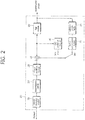
- FIG. 2 is a block diagram illustrating a configuration of a video decoding apparatus according to an embodiment.
- a scalable video encoding/decoding method or apparatus may be realized by extension of a general video encoding/decoding method or apparatus that does not provide scalability
- the block diagram of FIG. 2 illustrates an example of a video decoding apparatus which may form a basis for a scalable video decoding apparatus.
- the video decoding apparatus 200 includes an entropy decoding module 210, a dequantization module 220, an inverse transform module 230, an intra prediction module 240, a motion compensation module 250, a filter module 260, and a reference picture buffer 270.
- the video decoding apparatus 200 receives an input bitstream output from the encoding apparatus and decodes the bitstream in an intra mode or inter mode to output a reconstituted picture, that is, a reconstructed picture.
- a switch In the intra mode, a switch may be shifted to 'intra,' and in the inter mode, the switch may be shifted to 'inter.
- the video decoding apparatus 200 may obtain a residual block reconstructed from the input bitstream, generate a prediction block, and add the residual block and the prediction block to generate a reconstituted block, that is, a reconstructed block.
- the entropy decoding module 210 may entropy-decode the input bitstream according to probability distribution to generate symbols including a symbol in a form of a quantized coefficient.
- Entropy decoding is a method of receiving a binary sequence to generate symbols.
- the entropy decoding method is similar to the aforementioned entropy encoding method.
- the quantized coefficient is dequantized by the dequantization module 220 and inversely transformed by the inverse transform module 230, thereby generating a reconstructed residual block.
- the intra prediction module 240 may perform spatial prediction by using a pixel value of a pre-encoded block around a current block to generate a prediction block.
- the motion compensation module 250 may perform motion compensation using a motion vector and a reference picture stored in the reference picture buffer 270, thereby generating a prediction block.
- the reconstructed residual block and the prediction block are added by an adder 255, and the added blocks are subjected to the filter module 260.
- the filter module 260 may apply at least one of a deblocking filter, an SAO, and an ALF to the reconstructed block or the reconstructed picture.
- the filter module 260 outputs the reconstituted picture, that is, the reconstructed picture.
- the reconstructed picture may be stored in the reference picture buffer 270 to be used for inter prediction.
- components directly related to video decoding for example, the entropy decoding module 210, the dequantization module 220, the inverse transform module 230, the intra prediction module 240, the motion compensation module 250, the filter module 260 and the reference picture buffer 270 of the decoding apparatus 200 may be defined as a decoder or a decoding unit, separately from the other components.
- the decoding apparatus 200 may further include a parsing module (not shown) to parse information about an encoded video included in the bitstream.
- the parsing module may include the entropy decoding module 210 or be included in the entropy decoding module 210.
- the parsing module may be provided as one component of the decoding unit.
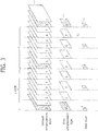
- FIG. 3 is a conceptual diagram schematically illustrating a scalable video coding structure using a plurality of layers according to an embodiment of the present invention.
- Group of Picture denotes a picture group, that is, a group of pictures.
- a transmission medium In order to transmit video data, a transmission medium is needed, and performance thereof is different by each transmission medium according to various network environments. For application to various transmission media or network environments, a scalable video coding method may be provided.
- the scalable video coding method is a coding method which utilizes texture information, motion information, residual signals between layers, or the like to remove redundancy between layers, thus improving encoding and decoding performance.
- the scalable video coding method may provide various scalabilities in spatial, temporal, quality and viewpoint aspects according to ambient conditions such as transmission bit rate, transmission error rate, and system resources.
- Scalable video coding may be performed by using a multi-layer structure so as to provide a bitstream applicable to various network situations.
- the scalable video coding structure may include a base layer in which video data is compressed and processed using a general video decoding method, and also include an enhancement layer in which video data is compressed and processed using both decoding information of the base layer and a general video decoding method.
- a layer refers to a set of pictures and bitstreams that are classified according to a spatial aspect (for example, picture size), a temporal aspect (for example, encoding order, picture output order and frame rate), picture quality, viewpoint, complexity, or the like.
- the base layer may refer to a lower layer or a reference layer
- the enhancement layer may refer to a higher layer.
- a plurality of layers may have dependency on each other.
- the base layer may be defined by standard definition (SD), 15 Hz frame rate and 1 Mbps bit rate
- a first enhancement layer may be defined by high definition (HD), 30 Hz frame rate and 3.9 Mbps bit rate
- a second enhancement layer may be defined by 4K-ultra high definition (UHD), 60 Hz frame rate and 27.2 Mbps.
- SD standard definition
- HD high definition
- UHD 4K-ultra high definition
- the first enhancement layer HD may be transmitted at a frame rate reduced to 15 Hz or lower.
- the scalable video coding method may provide spatial, temporal, quality and viewpoint scalabilities using the method described above with reference to FIG. 3 .
- Scalable video coding may refer to scalable video encoding in encoding, and to scalable video decoding in decoding.
- the present invention relates to a process of encoding/decoding a video including a plurality of layers or views, wherein the plurality of layers or views may be expressed as first, second, third and n-th layers or views.
- first layer may be represented as a base layer, and the second layer as an upper layer.
- the first layer may be also represented as a reference layer, and the second layer as an enhancement layer.
- a picture/block in the first layer corresponding to a second-layer picture/block may be adjusted to a size of the second-layer picture/block. That is, if a size of the first-layer picture/block is smaller than the size of the second-layer picture/block, the first-layer picture/block may be scaled using up-sampling or re-sampling.
- the first-layer picture may be added to a reference picture list for the second layer and used for encoding/decoding a second-layer video.
- the second layer may be subjected to prediction and encoding/decoding using the first-layer picture in the reference picture list, as in general inter prediction.
- a block for encoding/decoding may have a square shape with an N x N size, for example, 4 x 4, 8 x 8, 16 x 16, 32 x 32 and 64 x 64, or a rectangular shape with an N x M size, for example, 4 x 8, 16 x 8 and 8 x 32, and a block unit may be at least one of a coding block (CB), a prediction block (PB) and a transform block (TB), which may have different sizes.
- CB coding block
- PB prediction block
- TB transform block
- a method of generating a prediction block, that is, a prediction signal, of an encoding/decoding target block ("current block” or "target block") in an upper layer will be described in a method of encoding and decoding a scalable video, that is, a video using a multi-layer structure.
- the following method or apparatus may be generally applied to both an encoding apparatus and a decoding apparatus.
- vps_num_profile_tier_level_minus1 indicates a number of profile_tier_level() syntax structures in a VPS.
- vps_profile_present_flag[i] 1 indicates that profile and tier information is present in an i-th profile_tier_level() syntax structure
- vps_profile_present_flag[i] 0 indicates that the profile and tier information is not present in the i-th profile_tier_level() syntax structure but is inferred.
- profile_ref_minus1[i] indicates that the profile and tier information for the i-th profile_tier_level() sytanx structure is inferred to be equal to profile and tier information for a (profile ref_minus1[i]+1)-th profile_tier_level() syntax structure.
- profile_ref_minusl[i] plus 1 is less than or equal to i.
- profile and tier information for a first profile_tier_level() syntax structure needs to be inferred from a (profile_ref_minus1[1]+1)-th profile_tier_level() syntax structure. That is, profile_ref_minus1[1]+1 is required to be 1 or 0.
- profile_ref_minus1[1]+1 is 0, profile_ref_minus1[1] is -1, thus violating syntax definition of profile_ref_minus1[i] encoded in u(6).
- vps_profile_present_flag[1] needs to be always 1 for a first profile tier level syntax structure is added to the semantics of the syntax.
- semantics of vps_profile_present_flag[i] in Table 1 may be expressed as follows.
- vps_profile_present_flag[i] 1 indicates that the profile and tier information is present in the i-th profile_tier_level() syntax structure
- vps_profile_present_flag[i] 0 indicates that the profile and tier information is not present in the i-th profile_tier_level() syntax structure but is inferred.
- vps_profile_present_flag[1] for the first profile_tier_level syntax structure needs to be 1.
- a signaling method illustrated in Table 2 may be considered to resolve the foregoing problem.
- vps_num_profile_tier_level_minus1 indicates a number of profile_tier_level() syntax structures in a VPS.
- vps_profile_present_flag[i] 1 indicates that profile and tier information is present in an i-th profile_tier_level() syntax structure
- vps_profile_present flag[i] 0 indicates that the profile and tier information is not present in the i-th profile_tier_level() syntax structure but is inferred from profile and tier information on an (i-1)-th profile_tier_level() syntax structure.
- vps_profile_present_flag[1] for a first profile tier level syntax structure needs to be 1.
- profile_ref_minus1[1] is not signaled.
- VPS extension may be modified so that even Media Aware Network Equipment (MANE) having no entropy decoder may parse the VPS extension.
- Tables 3 to 5 illustrate VPSs according to various embodiments of the present invention. ⁇ Table 5> vps_extension( ) ⁇ Descriptor avc_base_layer_flag u(1) vps_vui_present_flag u(1) if(vps_vui_present_flag) vps_vui_offset u(16) ...
- vps_extension_offset transmitted via a VPS specifies a byte offset from a start point of a VPS NAL unit to fixed length coded information starting with syntax avc_base_layer_flag.
- vps_extension_offset enables access to pieces of basic information in the VPS NAL unit which does not need entropy decoding and enables session negotiations.
- the MANE having no entropy decoder may parse pieces of basic information not needing entropy decoding to use for session negotiations based on the byte offset value specified by vps_extension_offset.
- NumLayersInIdList as a variable specifying a number of layers in a layer identifier (ID) list needs to be entropy-decoded as a value calculated from information on layer sets specified after vps_extension_offset in Table 3, that is, layer_id_included_flag[i][j].
- information on layer sets may be specified in a VPS extension of Table 5.
- syntax elements relating to the layer sets specified in the VPS extension of Table 5 are as follows.
- vps_maximum_layer _id which is the same as vps_max_layer_id specified in the VPS, specifies a maximum allowed value of nuh_layer_id of all NAL units in a coding video sequence (CVS) and may have the same value as vps_max_layer _id described in the VPS.
- vps_number_layer_sets_minus1 specifies a number of layer sets and may be signaled prior to vps_vui_offset.
- layer_id_nuh_included_flag[i][j] 1 indicates that a value of nuh_layer_id equal to j is included in a layer identifier list, layerSetLayerIdList[i], and layer_id_nuh_included_flag[i][j] equal to 0 indicates that the value of nuh layer id equal to j is not included in layerSetLayerIdList[i].
- layer_id_nuh_included_flag[i][j] is required to have the same value as layer_id_included_flag[i][j] specified in the VPS.
- numLayersInIdList[i] and layerSetLayerIdList[i] may be obtained as follows, i being in a range of 1 to vps_number_layer_sets_minus1.
- VUI VPS video usability information
- HRD bitstream partition hypothetical reference decoder
- SEI bitstream partition HRD parameter supplemental enhancement information
- information on layers sets may be specified in a VPS extension of Table 6.
- Table 6 illustrates the information on the layer sets in the VPS extension, wherein session negotiations may be performed, without entropy decoding, using the output layer sets information in the VPS extension.
- Layer sets relating syntax elements, vps_maximum_layer_id, vps_number_layer_sets_minus1 and layer_id_nuh_included_flag[i][j], may be specified prior to vps_vui_offset.
- direct_dependency_flagindicating dependency between layers may be repositioned before vps_vui_offset.
- vps_vui information may be identified using vps_vui_offset without parsing a syntax element after vps_vui_offset.
- information on layer sets may be specified in a VPS extension of Table 7.
- layer sets relating syntax elements in the VPS may be positioned prior to vps_extension_offset.
- vps_num_layer_sets_minus1 which is conventionally encoded in variable bit ue(V) may be encoded in fixed bit u(10) to avoid entropy decoding, and vps_number_layer_sets_minus1 having the same function specified in the VPS extension may be deleted.
- VPS VUI video signaling information specified in VPS VUI is available for session negotiations, and the VPS VUI may be described in Table 8.
- video_signal_info_idx_present_flag 1 indicates that vps_num_video_signal_info_minus1 and vps_video_signal_info_idx[i] are present, and video_signal_info_idx_present_flag equal to 0 indicates that vps_num_video_signal_info_minus1 and vps_video_signal_info_idx[i] are absent.
- vps_num_video_signal_info_minu1 plus 1 indicates a number of video_signal_info() syntax structures in a VPS. In the absence of vps_num_video_signal_info_minu1, a number of vps_num_video_signal_info_minus1 is inferred to be equal to a MaxLayersMinus1 value.
- vps_video_signal_info_idx indicates an index of a video_signal_info() syntax structure list applied to a layer having nuh layer id equal to layer_id_in_nuh[i].
- vps_video_signal_info_idx[i] is inferred as (video_signal_info_idx_present_flag ? 0 : i).
- vps_video_signal_info_idx[i] may be in a range of 0 to vps_num_video_signal_info_minus1.
- the video signaling information may be specified at a position accessible without entropy decoding in Table 9.
- syntax elements relating to the video signaling information may be described in VPS_VUI following syntax elements relating to bit_rate and pic_rate, such as bit_rate_present_vps_flag, pic_rate_present_vps_flag, bit_rate_present_flag and pic_rate_present_flag.
- flag information indicating presence of a signal indicating a number of pieces of video signaling information video_signal_info and an index of video signaling information, that is, video_signal_info_idx_present_flag, is received following signals signaled using fixed bits, thereby accessing the video signaling information without entropy decoding.
- an aspect of the present invention suggests various methods for acquiring a number of active reference layer pictures used to decode a current picture for interlayer prediction.
- NumActiveRefLayerPics a variable specifying a number of active reference layer pictures used to decode a current picture for interlayer prediction, may be obtained as follows. According to a first method, all slices of a picture are defined to have the same NumActiveRefLayerPics value.
- all ref_layers_active_flag 1 indicates that for each picture referring to the VPS, the direct reference layer pictures that belong to all direct reference layers of the layer containing the picture, and that may be used for inter-layer prediction as specified by the values of sub_layers_vps_max_minus1[i] and max_tid_il_ref_pics_plus1[i][j] are present in the same access unit as the picture and are included in the inter-layer reference picture set of the picture.
- all_ref_layers_active_flag 0 indicates that the foregoing restriction may be applied or not be applied.
- all_ref_layers_active_flag may also be expressed as default_ref_layers_active_flag.
- variable NumDirectRefLayers[] specifies a number of direct reference layers of a current layer, calculated from direct_dependency_flag dpsecified in the VPS extension.
- sub_layers_vps_max_minus1[i] specifies maximum temporal sub-layer information on each layer
- max_tid_il_ref_pics_plus1[i][j] specifies maximum allowed value of temporal sub-layer allowing inter-layer prediction in each layer
- TemporalId specifies a temporal level of the current picture.
- Equation 1 among the direct reference layers of the layer including the current picture, only pictures in a reference layer with sub_layers_vps_max_minus1[i] greater than or equal to TemporalId of the current picture and with 'max_tild_il_ref_pics_plus1[i][j] for a current layer greater than TemporalId of the current picture may be considered as direct reference layer pictures available for decoding the current picture for interlayer prediction.
- Equation 1 may be replaced with Equation 2.
- Equation 2 variable NumDirectRefLayers[] specifies a number of direct reference layers of a current layer, calculated from direct_dependency_flag specified in the VPS extension.
- sub_layers_vps_max_minus1[i] specifies maximum temporal sub-layer information on each layer
- max_tid_il_ref_pics_plus1[i][j] specifies maximum allowed value of temporal sub-layer allowing inter-layer prediction in each layer
- TemporalId specifies a temporal level of the current picture.
- Equation 2 when max_tid_il_ref_pics_plus1[i][j] is 0, only pictures in a reference layer with max_tid_il_ref_pics_plus1[i][j] of 0 equal to TemporalId of the current picture and with sub_layers_vps_max_minus1[i] greater than or equal to TemporalId of the current picture, among the direct reference layers of the layer including the current picture, may be considered as reference layer pictures available for decoding the current picture for interlayer prediction. In this case, the pictures in the reference layer may be restricted to IRAP pictures.
- Equation 1 may be replaced with Equation 3.
- Equation 3 variable NumDirectRefLayers[] specifies a number of direct reference layers of a current layer, calculated from direct_dependency_flag specified in the VPS extension.
- sub_layers_vps_max_minus1[i] specifies maximum temporal sub-layer information on each layer
- max_tid_il_ref_pics_plus1[i][j] specifies maximum allowed value of temporal sub-layer allowing inter-layer prediction in each layer
- TemporalId specifies a temporal level of the current picture.
- Equation 1 for deriving, in a VPS level numRefLayerPics indicating a number of reference layer pictures available for decoding a sub-layer picture of each layer for all layers included in a bitstream may be replaced with Equation 4 or Equation 5.
- numRefLayerLayerPics may be replaced with numRefLayerPics[nuh_layer_id][TemporalId].
- variable NumDirectRefLayers[] specifies a number of direct reference layers of a current layer, calculated from direct_dependency_flag specified in the VPS extension.
- sub_layers_vps_max_minus1[i] specifies maximum temporal sub-layer information on each layer
- max_tid_il_ref_pics_plus1[i][j]' specifies maximum allowed value of temporal sub-layer allowing inter-layer prediction in each layer
- vps_max_sub_layers_minus1 specifiesmaximum number of temporal sub-layers that may be presented in all layers specified in the VPS.
- layer _id_in_nuh of reference layer pictures refers to nuh layer id present in a VCL NAL unit header.
- Equation 4 it is determined which sub-layer is used as a reference layer from a direct reference layer among sub-layers having a tid (Temporal) value of 0 to vps_max_sub_layers_minus1 with respect to each layer (0 ⁇ vps_max_layers_minus1) in a high level (for example, VPS).
- tid Temporal
- layer_id_in_nuh of the sub-layer may be applied to RefLayerIdListForTid[[lId][tId][k++].
- numRefLayerPics[lId][tId] specifies a number of referable sub-layers of a sub-layer with a tId value with respect to an lId layer.
- sub_layers_vps_max_minus1[] of a reference layer when sub_layers_vps_max_minus1[] of a reference layer is greater than or equal to TemporalId(tId) of the current picture and max_tild_il_ref_pics_plus1[][] of the reference layer is greater than TemporalId(tId) of the current picture which is 0, only pictures in the reference layer may be determined as reference layer pictures available for decoding the current picture for interlayer prediction.
- Equation 5 variable NumDirectRefLayers[] specifies a number of direct reference layers of a current layer, calculated from direct_dependency_flag specified in the VPS extension.
- sub_layers_vps_max_minus1[i] specifies maximum temporal sub-layer information on each layer
- max_tid_il_ref_pics_plus1[i][j] specifies maximum allowed value of temporal sub-layer allowing inter-layer prediction in each layer .
- layer_id_in_nuh of reference layer pictures refers to nuh_layer_id present in a VCL NAL unit header.
- Equation 5 it is determined which sub-layer is used as a reference layer from a direct reference layer among sub-layers having a tid (Temporal) value of 0 to sub_layers_vps_max_minus1 of maximum temporal sub-layer of each layer with respect to each layer (0 ⁇ vps_max_layers_minus1) in a high level (for example, VPS).
- a high level for example, VPS
- layer_id_in_nuh of the sub-layer may be applied to RefLayerIdListForTid[[lId][tId][k++].
- numRefLayerPics[lId][tId] specifies a number of referable sub-layers of a sub-layer with a tId value with respect to an lId layer.
- sub_layers_vps_max_minus1[] of a reference layer when sub_layers_vps_max_minus1[] of a reference layer is greater than or equal to TemporalId(tId) of the current picture and max_tild_il_ref_pics_plus1[][] of the reference layer is greater than TemporalId(tId) of the current picture which is 0, only pictures in the reference layer may be determined as reference layer pictures available for decoding the current picture for interlayer prediction.
- NumActiveRefLayerPics a number of active reference layer pictures used to decode a current picture for interlayer prediction, may be derived as follows. All slices of a picture are defined to have the same NumActiveRefLayerPics.
- NumActiveRefLayerPics a number of active reference layer pictures used to decode a current picture for interlayer prediction, may be derived as follows. All slices of a picture are defined to have the same NumActiveRefLayerPics.
- numRefLayerPics indicating a number of reference layer pictures available to decode the current picture for interlayer prediction is derived using NumDirectRefLayers[] specifying a number of direct reference layers of a current layer, sub_layers_vps_max_minus1[i] indicating maximum temporal sub-layer information on each layer, max_tid_il_ref_pics_plus1[i][j] indicating maximum allowed value of temporal sub-layer allowing inter-layer prediction in each layer , and TemporalId as temporal information on the current picture, calculated from syntax elements specified in the VPS extension, a slice segment header signaling pieces of information on pictures used for interlayer prediction may be described in Table 10.
- inter_layer_pred_enabled_flag is 1 and numRefLayerPics is greater than 1
- num_inter_layer_ref_pics_minus1 indicating a number of interlayer reference pictures
- inter_layer_pred_layer_idc[i] indicating an interlayer reference picture
- inter layer_pred_layer_idc[i] indicating the interlayer reference picture may not be signaled.
- inter_layer_pred_layer_idc[i] may have a value in a range of 0 to NumDirectRefLayers-1 of the layer including the current picture, and inter_layer_pred_layer_idc[i] may be inferred to be equal to refLayerPicIdc[i] derived by Equation 1 or 2 if not signaled.
- nuh_layer_id is nuh_layer_id of the current picture
- RefLayerId[][] is layer _id_in_nuh[] of a reference layer.
- nuh layer id is a layer ID specified in an NAL header of a current decoding target picture
- TemporalId is temporal information on the current decoding target picture, that is, sub-layer layer information.
- inter_layer_pred_enabled_flag is 1 and numRefLayerPics[nuh_layer_id][TemporalId] is greater than 1, num_inter_layer_ref_pics_minus1 indicating a number of interlayer reference pictures and inter_layer_pred_layer_idc[i] indicating an interlayer reference picture may be signaled.
- num_inter_layer_ref_pics_minus1 indicating the number of interlayer reference pictures may not be signaled.
- num_inter_layer_ref_pics_minus1 may have a value in a range of 0 to numRefLayerPics[nuh_layer_id][TemporalId]-1 derived by Equation 4 or 5.
- inter_layer_pred_layer_idc[i] may have a value in a range of 0 to numRefLayerPics[nuh_layer_id][TemporalId] of the layer including the current picture -1, and inter_layer_pred_layer_idc[i] may be inferred to be equal to index 'i' if not signaled.
- nuh_layer_id is nuh_layer_id of the current picture
- RefLayerIdListForTid[][] is a variable having a value of layer_id_in_nuh[] of a reference layer derived by Equation 4 or Equation 5.
- TargetDecLayerIdList as target decoding layer information and TargetOptLayerIdList as target output layer information are derived by Equation 8.
- variable TargetOptLayerSetIdx indicates a target output layer set index and may be converted into a layer set index by output_layer_set_idx_minus1[] specified the VPS extension.
- NumLayersInIdList specifies a number of layers included in a layer set
- TargetDecLayerIdList specifies a nuh_layer_id value of a layer to decode included in a layer set
- TargetOptLayerIdList indicates a nuh_layer_id value of a layer to output included in a layer set.
- output_layer_flag[][] is signaled based on a unit of output layer set in the VPS extension.
- output_layer_flag[i][j] for an i-th output layer set is not specified, i being in a range of 0 to vps_number_layer_sets_minus1, information on an output layer may not be normally identified.
- Equation 8 for deriving TargetDecLayerIdList as target decoding layer information TargetOptLayerIdList as target output layer information may be modified into Equation 9.
- output_layer_flag[i][j] of the i-th output layer set may be specified using Equation 9, i being in the range of 0 to vps_number_layer_sets_minus1.
- output_layer_flag[i][j] 1 indicates that a j-th layer in the i-th output layer set is a target output layer
- output_layer_flag[i][j] 0 indicates the j-th layer in the i-th output layer set is not a target output layer.
- TargetOptLayerIdList as a target output layer ID list including target output layer information may include a layer_id value of the j-th layer in the layer set indicated by target decoding layer set index TargetDecLayerSetIdx.
- TargetDecLayerSetIdx may be signaled from output layer set index information signaled via a VPS.
- TargetDecLayerIdList as a target decoding layer ID list including target decoding layer information may include the layer id value of the j-th layer in the layer set indicated by TargetDecLayerSetIdx.
- output_layer_flag[i][j] for an i-th output layer set, i being in a range of 0 to vps_number_layer_sets_minus1, may be inferred as below in (a) and (b), which may be stipulated in the standards.
- default_one_target_output_layer_idc is signaled to derive an output layer in an output layer and may have a value in a range of 0 to 3.
- default_one_target_output_layer_idc 0 may indicate that all layers in an output layer set are output, and default_one_target_output_layer_idc equal to 1 may indicate that only a highest layer, that is, a layer with a highest layer ID, among the layers included in the output layer set is output.
- default_one_target_output_layer_idc 2 may indicate only a layer with output layer flag equal to 1 is output.
- default_one_target_output_layer_idc 3 may be reserved for future use.
- vps number_layer_sets_minus1 specified in the VPS extension indicates a number of layer sets specified in the VPS. Since an MV-HEVC/SHVC bitstream includes two or more layer sets, vps_number_sets_minus1 is always greater than 1. Thus, vps_number_layer_sets_minus1 encoded in u(10) may be specified to have a value in a range of 1 to 1023. Alternatively, vps_number_layer_sets_minus1 is changed into vps_number_layer_sets_minus2, which may be specified to have a value in a range of 0 to 1022.
- the present invention provides a method of indicating a non-reference picture unnecessary for interlayer prediction.
- a picture with a highest temporal ID is marked as a reference picture or non-reference picture as in Equation 10.
- currTid indicates a temporal ID of a currently decoded picture
- max_tid_il_ref_pics_plus1[iLidx][jLidx] indicates maximum temporal ID information allowing interlayer prediction in a current layer, which is signaled via the VPS.
- max_tid_il_ref_pics_plus1[iLidx][jLidx] is signaled by upper layer with dependency on the current layer.
- the currently decoded picture is used as a reference layer for any one of the upper layers with dependency, the currently decoded picture is marked as "reference picture” or "used for reference.”
- remainingInterLayerReferencesFlag indicating a reference picture for one of the upper layers with dependency is 1 in Equation 10
- a process of determining remainingInterLayerReferenceFlag values of the remaining upper layers may be omitted and the currently decoded picture may not be changed to a non-reference picture. That is, the currently decoded picture may be considered as a reference picture.
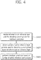
- FIG. 4 is a flowchart illustrating a video decoding method according to the present invention.
- the decoding apparatus may receive information on a reference layer used for decoding a current picture for interlayer prediction (S410).
- the information on the reference layer may include flag information and information on numbers, such as direct_dependency_flag[i][[j] indicating whether a layer with a j index is a direct reference layer for a layer with an i index, sub_layers_vps_max_minus1[i] indicating maximum temporal sub-layer information on each layer, max_tid_il_ref_pics_plus1[i][j] indicating maximum allowed value of temporal sub-layer allowing inter-layer prediction in each layer , a temporal sub-layer ID of the current picture, all_ref_layers_active_flag indicating whether a reference layer picture available for interlayer prediction is present in the same AU as the current picture and included in an interlayer reference picture set of the current picture, the reference layer picture being included in all direct reference layers of a current layer including the current picture and specified by maximum temporal sub-layer information on each layer and maximum allowed value of temporal sub-layer allowing inter-layer prediction in each layer , inter _layer_
- the decoding apparatus derives a number of active reference layer pictures used for decoding the current picture based on the information on the reference layer (S420).
- All slices belonging to the current picture may the same number of active reference layer pictures.
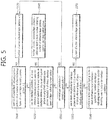
- FIG. 5 illustrates a method of deriving a number of active reference layer pictures according to an embodiment of the present invention. A process of deriving the number of active reference layer pictures according to the embodiment will be described below with reference to FIG. 5 .
- a layer ID of a current layer including a current picture is 0 or a number of direct reference layers of the current layer including the current picture is 0 (S510).
- the number of active reference layer pictures is derived to be 0 (S520).
- the layer ID of the current layer is 0 or the number of direct reference layers of the current layer is not 0, it is determined whether all direct reference pictures present in the same AU as that of the current picture and included in an interlayer reference picture set of the current picture among direct reference layer pictures included in all the direct reference layers of the layer including the current picture are used for interlayer prediction (S530).
- Operation S530 may be determined based on flag information all_ref_layers _active flag.
- all_ref_layers_active_flag is equal to 1
- the number of active reference layer pictures may be derived to be equal to a reference layer picture number indicating a number of reference layer pictures used for decoding the current picture (S540).
- the reference layer picture number is derived based on a variable indicating the number of direct reference layers of the current layer, maximum temporal sub-layer information on each layer, maximum allowed value of temporal sub-layer allowing inter-layer prediction in each layer , and a temporal ID of the current picture.
- pictures in a reference layer which has maximum temporal sub-layer information greater than or equal to the temporal ID of the current picture and maximum temporal sub-layer information for the current layer greater than the temporal ID of the current picture may be considered as reference layer pictures available for decoding the current picture for interlayer prediction.
- interlayer er_pred_enabled_flag When all ref layers _active flag is 0, it is determined through interlayer er_pred_enabled_flag whether interlayer prediction is used for decoding the current picture (S550). When inter layer_pred_enabled_flag is 0, the number of active reference layer pictures is derived to be 0 (S520).
- the number of active reference layer pictures may be derived to be a value of reference layer information specified by num_inter_layer_ref_pics_minus1 indicating a number of pictures used for decoding the current picture for interlayer prediction (S580).
- the decoding apparatus when the number of active reference layer pictures is derived, the decoding apparatus performs interlayer prediction based on the number of active reference layer pictures (S430).
- the present invention provides a method of signaling layer information present in a video encoded bitstream of a multilayer structure including a temporal layer, an interlayer prediction method, a method of obtaining a target output layer and an apparatus using the same.
- the present invention also provides a method of accessing layer information specified in a VPS in a bitstream for session negotiations without an entropy decoder and an apparatus using the same.
Landscapes
- Engineering & Computer Science (AREA)
- Multimedia (AREA)
- Signal Processing (AREA)
- Health & Medical Sciences (AREA)
- Audiology, Speech & Language Pathology (AREA)
- Human Computer Interaction (AREA)
- Physics & Mathematics (AREA)
- Acoustics & Sound (AREA)
- Computational Linguistics (AREA)
- Compression Or Coding Systems Of Tv Signals (AREA)
- Compression, Expansion, Code Conversion, And Decoders (AREA)
Abstract
Description
- The present invention relates to video encoding and decoding, and more particularly, to methods and apparatuses for encoding and decoding a video supporting a plurality of layers in a bitstream.
- In recent years, as high definition (HD) broadcast services are spreading domestically and globally, a large number of users are getting used to high-resolution and high-quality videos and accordingly institutions put spurs to the development of next-generation video devices. Also, with growing interest in ultrahigh-definition (UHD) services having a resolution four times higher than HDTV, compression techniques for higher-quality videos are needed.
- For video compression, there may be used an inter prediction technique of predicting pixel values included in a current picture from temporally previous and/or subsequent pictures of the current picture, an intra prediction technique of predicting pixel values included in a current picture using pixel information in the current picture, or an entropy encoding technique of assigning a short code to a symbol with a high appearance frequency and assigning a long code to a symbol with a low appearance frequency.
- Video compression technology may include a technique of providing a constant network bandwidth in restricted operating environments of hardware without considering variable network environments. However, to compress video data used for network environments involving frequent changes of bandwidths, new compression techniques are required, wherein a scalable video encoding/decoding method may be employed.
- An aspect of the present invention is to provide a method of signaling layer information contained in a video encoded bitstream of a multilayer structure including a temporal layer, an interlayer prediction method and a method of obtaining a target output layer.
- Another aspect of the present invention is to provide a method of accessing layer information specified in a video parameter set (VPS) in a bitstream for session negotiations without an entropy decoder and an apparatus using the same.
- Still another aspect of the present invention is to provide a method of identifying a number of active interlayer reference pictures needed for decoding a current picture for utilization in interlayer prediction, a method of obtaining a target output layer and an apparatus using the same.
- An aspect of the present invention provides a method of decoding a video supporting a plurality of layers, the method including receiving information on a reference layer used for decoding a current picture for interlayer prediction; deriving a number of active reference layer pictures used for decoding the current picture based on the information on the reference layer; and performing interlayer prediction based on the number of active reference layer pictures.
- All slices of the current picture may have the same number of active reference layer pictures.
- When a layer identifier of a current layer including the current picture is 0, the number of active reference layer pictures may be derived to be 0.
- When a number of direct reference layers of the current layer including the current picture is 0, the number of active reference layer pictures may be derived to be 0.
- When a number of refernece layer pictures, derived based on a number of direct reference layers of the current layer, maximum temporal sub-layer information of a reference layer, maximum allowed value of temporal sub-layer allowing inter-layer prediction in the reference layer and a temporal identifier of the current picture, in the same acess unit as that of the current picture is 0, the number of active reference layer pictures may be derived to be 0..
- When a layer identifier of the current layer including the current picture is 0 or a number of reference layer pictures available for interlayer prediction in the same access unit as that of the current picture is not 0, and all direct reference layer pictures belonging to all direct reference layers of the current layer including the current picture, being present in the same access unit as that of the current picture and being included in an interlayer reference picture set of the current picture are used as reference layer pictures for the current picture, the number of active reference layer pictures may be derived based on a variable indicating a number of direct reference layers of the current layer, maximum temporal sub-layer information on each layer, maximum allowed value of temporal sub-layer allowing inter-layer prediction in each layer and the temporal identifier of the current picture.
- A number of pictures in a reference layer having maximum temporal sub-layer information greater than or equal to the temporal identifier of the current picture and maximum temporal sub-layer information allowing interlayer prediction greater than the temporal identifier of the current picture, among direct reference layer pictures for the current picture, may be used as the number of active reference layer pictures for decoding the current picture.
- When interlayer prediction is not used for decoding the current picture, the number of active reference layer pictures may be derived to be 0.
- When at most one picture is used for interlayer prediction for each picture in a coding video sequence or a number of direct reference layers of the layer including the current picture is 1, the number of active reference layer pictures may be derived to be 1.
- When at most one picture is used for interlayer prediction for each picture in a coding video sequence or a number of direct reference layers of the layer including the current picture is 1, the number of active reference layer pictures may be derived to be 1 if a number of reference layer pictures available for decoding the current picture is greater than 0, and the number of active reference layer pictures may be derived to be 0 if the number of reference layer pictures available for decoding the current picture is 0.
- When at most one picture is used for interlayer prediction for each picture in a coding video sequence or a number of reference layer pictures available for interlayer prediction in the same access unit as that of the current picture is 1, the number of active reference layer pictures may be derived to be 1.
- When the information on the reference layer includes number information indicating a number of pictures used for decoding the current picture for interlayer prediction, the number of active reference layer pictures may be derived to be a value specified by the number information.
- According to an embodiment of the present invention, there are provided a method of signaling layer information present in a video encoded bitstream of a multilayer structure including a temporal layer, an interlayer prediction method, and a method of obtaining a target output layer.
- According to another embodiment of the present invention, there are provided a method enabling even Media Aware Network Equipment (MANE) having no entropy decoder to access layer information in a bitstream for session negotiations and an apparatus using the same.
- According to still another embodiment of the present invention, there are provided a method of accurately identifying a number of active interlayer reference pictures needed for decoding a current picture for utilization in interlayer prediction, a method of obtaining a target output layer and an apparatus using the same.
-
-
FIG. 1 is a block diagram illustrating a configuration of a video encoding apparatus according to an embodiment. -
FIG. 2 is a block diagram illustrating a configuration of a video decoding apparatus according to an embodiment. -
FIG. 3 is a conceptual diagram schematically illustrating a scalable video coding structure using a plurality of layers according to an embodiment of the present invention. -
FIG. 4 is a flowchart illustrating a video decoding method according to the present invention. -
FIG. 5 illustrates a method of deriving a number of active reference layer pictures according to an embodiment of the present invention. - Hereinafter, embodiments of the present invention are described in detail with reference to the accompanying drawings. In describing the embodiments of the present invention, a detailed description of related known elements or functions will be omitted if it is deemed to make the gist of the present invention unnecessarily vague.
- It will be understood that when an element is referred to as being "connected" or "coupled" to another element, the element can be directly connected or coupled to another element or intervening elements. Also, when it is said that a specific element is "included," it may mean that elements other than the specific element are not excluded and that additional elements may be included in the embodiments of the present invention or the scope of the technical spirit of the present invention.
- Although the terms "first," "second," etc. may be used to describe various elements, these elements should not be limited by these terms. These terms are used only to distinguish one element from another element. For example, a first element may be named a second element without departing from the scope of the present invention. Likewise, a second element may be named a first element.
- Although components described in the embodiments of the present invention are independently illustrated in order to show different characteristic functions, such a configuration does not indicate that each component is constructed by a separate hardware constituent unit or software constituent unit. That is, each component includes individual components that are arranged for convenience of description, in which at least two components may be combined into a single component or a single component may be divided into a plurality of components to perform functions. It is to be noted that embodiments in which some components are integrated into one combined component and/or a component is divided into multiple separate components are included in the scope of the present invention without departing from the essence of the present invention.
- Some constituent elements are not essential to perform the substantial functions in the invention and may be optional constituent elements for merely improving performance. The present invention may be embodied by including only constituent elements essential to implement the spirit of the invention other than constituent elements used for merely improving performance. A structure including only the essential constituent elements other than optional constituents used for merely improving performance also belongs to the scope of the present invention.
-
FIG. 1 is a block diagram illustrating a configuration of a video encoding apparatus according to an embodiment. A scalable video encoding/decoding method or apparatus may be realized by extension of a general video encoding/decoding method or apparatus that does not provide scalability, and the block diagram ofFIG. 1 illustrates an example of a video encoding apparatus which may form a basis for a scalable video encoding apparatus. - Referring to
FIG. 1 , thevideo encoding apparatus 100 includes amotion estimation module 111, amotion compensation module 112, anintra prediction module 120, aswitch 115, asubtractor 125, atransform module 130, a quantization module140, anentropy encoding module 150, an dequantization module160, aninverse transform module 170, anadder 175, afilter module 180, and areference picture buffer 190. - The
video encoding apparatus 100 may encode an input picture images in an intra mode or an inter mode and output a bitstream. Intra prediction means an intra-picture prediction, and inter prediction means an inter-picture prediction. In the intra mode, theswitch 115 is shifted to 'intra,' and in the inter mode, theswitch 115 is shifted to 'inter.' Thevideo encoding apparatus 100 may generate a prediction block for an input block of the input picture and then encode a difference between the input block and the prediction block. - In the intra mode, the
intra prediction module 120 may perform spatial prediction by using a pixel value of a pre-encoded block around a current block to generate a prediction block. - In the inter mode, the
motion estimation module 111 may obtain a region which is most matched with the input block in the reference picture stored in thereference picture buffer 190 during a motion estimation process to derive a motion vector. Themotion compensation module 112 may perform motion compensation using the motion vector and the reference picture stored in thereference picture buffer 190, thereby generating the prediction block. - The
subtractor 125 may generate a residual block based on the difference between the input block and the generated prediction block. Thetransform module 130 may transform the residual block to output a transform coefficient. Thequantization module 140 may quantize the transform coefficient according to a quantization parameter to output a quantized coefficient. - The
entropy encoding module 150 may entropy-encode a symbol according to probability distribution based on values derived by thequantization module 140 or an encoding parameter value derived in encoding, thereby outputting a bitstream. Entropy encoding is a method of receiving symbols having different values and representing the symbols as a decodable binary sequence or string while removing statistical redundancy. - Here, a symbol means a syntax element as an encoding/decoding target, a coding parameter, a value of a residual signal, or the like. A coding parameter, which is a parameter necessary for encoding and decoding, may include information encoded by the encoding apparatus and transferred to the decoding apparatus, such as a syntax element, and information to be inferred during an encoding or decoding process and means information necessary for encoding and decoding a picture. The coding parameter may include, for example, values or statistics of an intra/inter prediction mode, a movement/motion vector, a reference picture index, a coding block pattern, presence and absence of a residual signal, a transform coefficient, a quantized transform coefficient, a block size and block partition information. A residual signal may denote a difference between an original signal and a prediction signal, a transformed signal of the difference between the original signal and the prediction signal, or a transformed and quantized signal of the difference between the original signal and the prediction signal. The residual signal may be referred to as a residual block in a block unit.
- When entropy encoding is applied, a symbol having a high probability is allocated a small number of bits and a symbol having a low probability is allocated a large number of bits in representation of symbols, thereby reducing a size of bit strings for symbols to be encoded. Accordingly, entropy encoding may enhance compression performance of video encoding.
- For entropy encoding, encoding methods, such as exponential Golomb, context-adaptive variable length coding (CAVLC) and context-adaptive binary arithmetic coding (CABAC), may be used. For example, a table used for performing entropy encoding, such as a variable length coding/code (VLC) table, may be stored in the
entropy encoding module 150, and theentropy encoding module 150 may perform entropy encoding using the stored VLC table. In addition, theentropy encoding module 150 may derive a binarization method of a target symbol and a probability model of a target symbol/bin and perform entropy encoding using the derived binarization method or probability model. - The quantized coefficient may be dequantized by the dequantization module160 and inversely transformed by the
inverse transform module 170. The dequantized and inversely transformed coefficient is added to the prediction block by theadder 175, thereby generating a reconstructed block. - The reconstructed block is subjected to the
filter module 180, and thefilter module 180 may apply at least one of a deblocking filter, a sample adaptive offset (SAO), and an adaptive loop filter (ALF) to the reconstructed block or a reconstructed picture. The reconstructed block obtained via thefilter module 180 may be stored in thereference picture buffer 190. -
FIG. 2 is a block diagram illustrating a configuration of a video decoding apparatus according to an embodiment. As described above inFIG. 1 , a scalable video encoding/decoding method or apparatus may be realized by extension of a general video encoding/decoding method or apparatus that does not provide scalability, and the block diagram ofFIG. 2 illustrates an example of a video decoding apparatus which may form a basis for a scalable video decoding apparatus. - Referring to
FIG. 2 , thevideo decoding apparatus 200 includes anentropy decoding module 210, adequantization module 220, aninverse transform module 230, anintra prediction module 240, amotion compensation module 250, afilter module 260, and areference picture buffer 270. - The
video decoding apparatus 200 receives an input bitstream output from the encoding apparatus and decodes the bitstream in an intra mode or inter mode to output a reconstituted picture, that is, a reconstructed picture. In the intra mode, a switch may be shifted to 'intra,' and in the inter mode, the switch may be shifted to 'inter. Thevideo decoding apparatus 200 may obtain a residual block reconstructed from the input bitstream, generate a prediction block, and add the residual block and the prediction block to generate a reconstituted block, that is, a reconstructed block. - The
entropy decoding module 210 may entropy-decode the input bitstream according to probability distribution to generate symbols including a symbol in a form of a quantized coefficient. Entropy decoding is a method of receiving a binary sequence to generate symbols. The entropy decoding method is similar to the aforementioned entropy encoding method. - The quantized coefficient is dequantized by the
dequantization module 220 and inversely transformed by theinverse transform module 230, thereby generating a reconstructed residual block. - In the intra mode, the
intra prediction module 240 may perform spatial prediction by using a pixel value of a pre-encoded block around a current block to generate a prediction block. In the inter mode, themotion compensation module 250 may perform motion compensation using a motion vector and a reference picture stored in thereference picture buffer 270, thereby generating a prediction block. - The reconstructed residual block and the prediction block are added by an
adder 255, and the added blocks are subjected to thefilter module 260. Thefilter module 260 may apply at least one of a deblocking filter, an SAO, and an ALF to the reconstructed block or the reconstructed picture. Thefilter module 260 outputs the reconstituted picture, that is, the reconstructed picture. The reconstructed picture may be stored in thereference picture buffer 270 to be used for inter prediction. - Among the
entropy decoding module 210, thedequantization module 220, theinverse transform module 230, theintra prediction module 240, themotion compensation module 250, thefilter module 260 and thereference picture buffer 270 of thedecoding apparatus 200, components directly related to video decoding, for example, theentropy decoding module 210, thedequantization module 220, theinverse transform module 230, theintra prediction module 240, themotion compensation module 250 and thefilter module 260 may be defined as a decoder or a decoding unit, separately from the other components. - Further, the
decoding apparatus 200 may further include a parsing module (not shown) to parse information about an encoded video included in the bitstream. The parsing module may include theentropy decoding module 210 or be included in theentropy decoding module 210. The parsing module may be provided as one component of the decoding unit. -
FIG. 3 is a conceptual diagram schematically illustrating a scalable video coding structure using a plurality of layers according to an embodiment of the present invention. InFIG. 3 , Group of Picture (GOP) denotes a picture group, that is, a group of pictures. - In order to transmit video data, a transmission medium is needed, and performance thereof is different by each transmission medium according to various network environments. For application to various transmission media or network environments, a scalable video coding method may be provided.
- The scalable video coding method is a coding method which utilizes texture information, motion information, residual signals between layers, or the like to remove redundancy between layers, thus improving encoding and decoding performance. The scalable video coding method may provide various scalabilities in spatial, temporal, quality and viewpoint aspects according to ambient conditions such as transmission bit rate, transmission error rate, and system resources.
- Scalable video coding may be performed by using a multi-layer structure so as to provide a bitstream applicable to various network situations. For example, the scalable video coding structure may include a base layer in which video data is compressed and processed using a general video decoding method, and also include an enhancement layer in which video data is compressed and processed using both decoding information of the base layer and a general video decoding method.
- Here, a layer refers to a set of pictures and bitstreams that are classified according to a spatial aspect (for example, picture size), a temporal aspect (for example, encoding order, picture output order and frame rate), picture quality, viewpoint, complexity, or the like. Further, the base layer may refer to a lower layer or a reference layer, and the enhancement layer may refer to a higher layer. A plurality of layers may have dependency on each other.
- Referring to
FIG. 3 , for example, the base layer may be defined by standard definition (SD), 15 Hz frame rate and 1 Mbps bit rate, a first enhancement layer may be defined by high definition (HD), 30 Hz frame rate and 3.9 Mbps bit rate, and a second enhancement layer may be defined by 4K-ultra high definition (UHD), 60 Hz frame rate and 27.2 Mbps. These formats, frame rates and bit rates are provided only for illustrative purposes and may be changed and modified as needed. Also, a number of used layers may change depending on circumstances, without being limited to the present embodiment. - For instance, when a transmission bandwidth is 4 Mbps, the first enhancement layer HD may be transmitted at a frame rate reduced to 15 Hz or lower. The scalable video coding method may provide spatial, temporal, quality and viewpoint scalabilities using the method described above with reference to
FIG. 3 . - Scalable video coding may refer to scalable video encoding in encoding, and to scalable video decoding in decoding.
- The present invention relates to a process of encoding/decoding a video including a plurality of layers or views, wherein the plurality of layers or views may be expressed as first, second, third and n-th layers or views. Although the following description will be made with reference to a picture including a first layer and a second layer, the same process may be applied to pictures including two or more layers or views. The first layer may be represented as a base layer, and the second layer as an upper layer. Further, the first layer may be also represented as a reference layer, and the second layer as an enhancement layer.
- A picture/block in the first layer corresponding to a second-layer picture/block may be adjusted to a size of the second-layer picture/block. That is, if a size of the first-layer picture/block is smaller than the size of the second-layer picture/block, the first-layer picture/block may be scaled using up-sampling or re-sampling.
- The first-layer picture may be added to a reference picture list for the second layer and used for encoding/decoding a second-layer video. Here, the second layer may be subjected to prediction and encoding/decoding using the first-layer picture in the reference picture list, as in general inter prediction.
- A block for encoding/decoding may have a square shape with an N x N size, for example, 4 x 4, 8 x 8, 16 x 16, 32 x 32 and 64 x 64, or a rectangular shape with an N x M size, for example, 4 x 8, 16 x 8 and 8 x 32, and a block unit may be at least one of a coding block (CB), a prediction block (PB) and a transform block (TB), which may have different sizes.
- Hereinafter, a method of generating a prediction block, that is, a prediction signal, of an encoding/decoding target block ("current block" or "target block") in an upper layer will be described in a method of encoding and decoding a scalable video, that is, a video using a multi-layer structure. The following method or apparatus may be generally applied to both an encoding apparatus and a decoding apparatus.
- Meanwhile, according to a current draft of Scalable High Efficiency Video Coding (SHVC) and Multiview-High Efficiency Video Coding (MV-HEVC) standards, profile tier level specifying a profile, tier and level used for a layer set in a video parameter set (VPS) extension is described in Table 1.
< Table 1> vps_extension() { Descriptor ... vps_num_profile_tier_level_minus1 u(6) for(i = 1; i <= vps_num_profile_tier_level_minus1; i++) { vps_profile_present_flag[i] u(1) if(!vps_profile_present_flag[i]) profile_ref_minus1[i] u(6) profile_tier_level(vps_profile_present_flag[i], vps_max_sub_layers_minus1) } - Referring to Table 1, a value specified by vps_num_profile_tier_level_minus1 indicates a number of profile_tier_level() syntax structures in a VPS.
- vps_profile_present_flag[i] equal to 1 indicates that profile and tier information is present in an i-th profile_tier_level() syntax structure, and vps_profile_present_flag[i] equal to 0 indicates that the profile and tier information is not present in the i-th profile_tier_level() syntax structure but is inferred.
- profile_ref_minus1[i] indicates that the profile and tier information for the i-th profile_tier_level() sytanx structure is inferred to be equal to profile and tier information for a (profile ref_minus1[i]+1)-th profile_tier_level() syntax structure. Here, profile_ref_minusl[i] plus 1 is less than or equal to i.
- According to the current draft of the standards in Table 1, when i is 1 and vps_profile_present_flag[1] is 0, profile and tier information for a first profile_tier_level() syntax structure needs to be inferred from a (profile_ref_minus1[1]+1)-th profile_tier_level() syntax structure. That is, profile_ref_minus1[1]+1 is required to be 1 or 0. When profile_ref_minus1[1]+1 is 0, profile_ref_minus1[1] is -1, thus violating syntax definition of profile_ref_minus1[i] encoded in u(6).
- Further, when (profile_ref_minus1[1]+1) is 1, a problem may occur that first profiled and tier information is required to be inferred from a first profile_tier_level syntax structure.
- To address this problem, a restriction that vps_profile_present_flag[1] needs to be always 1 for a first profile tier level syntax structure is added to the semantics of the syntax. In this case, semantics of vps_profile_present_flag[i] in Table 1 may be expressed as follows.
- vps_profile_present_flag[i] equal to 1 indicates that the profile and tier information is present in the i-th profile_tier_level() syntax structure, and vps_profile_present_flag[i] equal to 0 indicates that the profile and tier information is not present in the i-th profile_tier_level() syntax structure but is inferred. vps_profile_present_flag[1] for the first profile_tier_level syntax structure needs to be 1.
- Alternatively, a signaling method illustrated in Table 2 may be considered to resolve the foregoing problem.
< Table 2> vps_extension() { Descriptor avc_base_layer_flag u(1) ... vps_num_profile_tier_level_minus1 u(6) for(i = 1; i <= vps_num_profile_tier_level_minus1; i ++) { vps_profile_present_flag[i] u(1) profile_tier_level(vps_profile_present_flag[i], vps_max_sub_layers_minus1) } ... } - Referring to Table 2, a value specified by vps_num_profile_tier_level_minus1 indicates a number of profile_tier_level() syntax structures in a VPS.
- vps_profile_present_flag[i] equal to 1 indicates that profile and tier information is present in an i-th profile_tier_level() syntax structure, and vps_profile_present flag[i] equal to 0 indicates that the profile and tier information is not present in the i-th profile_tier_level() syntax structure but is inferred from profile and tier information on an (i-1)-th profile_tier_level() syntax structure. vps_profile_present_flag[1] for a first profile tier level syntax structure needs to be 1.
- According to Table 2, profile_ref_minus1[1] is not signaled.
- Alternatively, syntax structures of the VPS may be modified so that even Media Aware Network Equipment (MANE) having no entropy decoder may parse the VPS extension. Tables 3 to 5 illustrate VPSs according to various embodiments of the present invention.


< Table 5> vps_extension( ) { Descriptor avc_base_layer_flag u(1) vps_vui_present_flag u(1) if(vps_vui_present_flag) vps_vui_offset u(16) ... u(1) all_ref_layers_active_flag u(1) vps_maximum_layer_id u(1) vps_number_layer_sets_minus1 u(10) for(i = 1; i <= vps_number_layer_sets_minus1; i++) for(j =0;j <= vps_maximum_layer_id; j++) layer_id_nuh_included_flag[i][j] u(1) vps_num_profile_tier_level-minus1 u(6) for(i = 1; i <= vps_num_profile_tier_level_minus1; i ++) { vps_profile_present_flag[i] u(1) if(!vps_profile_present_flag[i]) profile_ref_minus1[i] u(6) profile_tier_level(vps_profile_present_flag[i], vps_max_sub_layers_minus1) } NumOutputLayerSets = vps_number_layer_sets_minus1 + 1 more_output_layer_sets_than_default_flag u(1) if(more_output_layer_sets_than_default_flag) { num add output layer sets minus1 u(10) numOutputLayerSets += num_add_output_layer_sets_minus1 + 1 } if(numOutputLayet-Sets > 1) default_one_target_output_layer_idc u(2) for(i = 1; i <numOutputLayerSets; i++) { if(i > vps_number_layer_sets_minus1) { output_layer_set_idx_minus1[i] u(v) lsIdx = output_layer_set_idx_minus1[i] + 1 for(j = 0 ;j <NumLayersInIdList[lsIdx] - 1; j++) output_layer_flag[i][j] u(1) } profile_level_tier_idx[i] u(v) } ... } - Referring to Table 3, vps_extension_offset transmitted via a VPS specifies a byte offset from a start point of a VPS NAL unit to fixed length coded information starting with syntax avc_base_layer_flag.
- The byte offset defined by vps_extension_offset enables access to pieces of basic information in the VPS NAL unit which does not need entropy decoding and enables session negotiations.
- For example, the MANE having no entropy decoder may parse pieces of basic information not needing entropy decoding to use for session negotiations based on the byte offset value specified by vps_extension_offset.
- When the MANE having no entropy decoder parses output layer sets information in a VPS extension of Table 4 based on vps_extension_offset information for session negotiations without entropy-decoding information after vps_extension_offset, NumLayersInIdList as a variable specifying a number of layers in a layer identifier (ID) list needs to be entropy-decoded as a value calculated from information on layer sets specified after vps_extension_offset in Table 3, that is, layer_id_included_flag[i][j].
- To make the output layer sets information in the VPS extension available for session negotiations without entropy decoding, information on layer sets may be specified in a VPS extension of Table 5.
- Meanwhile, semantics of syntax elements relating to the layer sets specified in the VPS extension of Table 5 are as follows.
- vps_maximum_layer _id, which is the same as vps_max_layer_id specified in the VPS, specifies a maximum allowed value of nuh_layer_id of all NAL units in a coding video sequence (CVS) and may have the same value as vps_max_layer _id described in the VPS.
- vps_number_layer_sets_minus1 specifies a number of layer sets and may be signaled prior to vps_vui_offset.
- Similar to layer_id_included_flag[i][j] specified in the VPS, layer_id_nuh_included_flag[i][j] equal to 1 indicates that a value of nuh_layer_id equal to j is included in a layer identifier list, layerSetLayerIdList[i], and layer_id_nuh_included_flag[i][j] equal to 0 indicates that the value of nuh layer id equal to j is not included in layerSetLayerIdList[i]. layer_id_nuh_included_flag[i][j] is required to have the same value as layer_id_included_flag[i][j] specified in the VPS.
- numLayersInIdList[i] and layerSetLayerIdList[i] may be obtained as follows, i being in a range of 1 to vps_number_layer_sets_minus1.
              n=0
              for (m = 0; m <= vps_maximum_layer_id; m++)
                    if (layer_id_nuh_included_flag[i][m])
                          layerSetLayerIdList[i][n++] = m
              numLayersInIdList[i] = n
| vps_extension() { | Descriptor |
| avc_base_layer_flag | u(1) |
| vps_maximum_layer_id | u(1) |
| vps_number_layer_sets_minus1 | u(10) |
| for(i = 1;i <= vps_number_layer_sets_minus1;i++) | |
| for(j = 0; j <= vps_maximum_layer_id; j++) | |
| layer_id_nuh_included_flag[i][j] | u(1) |
| for(i = 1;i <= MaxLayersMinus1; i++) | |
| for(j + 0:j <i;j++) | |
| direct_dependency_flag[i][j] | u(1) |
| vps_vui_present_flag | u(1) |
| if(vps_vui_present_flag) | |
| vps_vui_offset | u(16) |
| splitting flag | u(1) |
| for(i = 0, NumScalabilityTypes = 0; i < 16; i++) { | |
| scalability_mask_flag[i] | u(1) |
| NumScalabilityTypes += scalability_mask_flag[i] | |
| } | |
| for(j = 0; j < (NumScalabilityTypes - splitting_flag); j++) | |
| dimension_id_len_minus1[j] | u(3) |
| vps_nuh_layer_id_present_flag | u(1) |
| ... | |
| } |

| vps_vui(){ | Descriptor |
| cross_layer-pic_type_aligned_flag | u(1) |
| if(!cross_layer_pic_type_aligned_flag) | |
| cross_layer_irap_aligned_flag | u(1) |
| bit_rate_present_vps_flag | u(1) |
| pic_rate_present_vps_flag | u(1) |
| ... | |
| ilp_restricted_ref_layers_flag | u(1) |
| if(ilp_restricted_ref_layers_flag) | |
| for(i= 1;i <= MaxLayersMinus1; i++) | |
| for(j = 0; j < NumDirectRefLayers[layer_id_in_nuh[i]]; j++) { | |
| min_spatial_segment_offset_plus1[i][j] | ue(v) |
| if(min_spatial_segment_offset_plus1[i][j]> 0) { | |
| ctu_based_offset_enabled_flag[i][j] | u(1) |
| if(ctu_based_offset_enabled_flag[i][j]) | |
| min_horizontal_ctu_offset_plus1[i][j] | ue(v) |
| } | |
| } | |
| video_signal_info_idx_present_flag | u(1) |
| if(video_signal_info_idx_present_flag) | |
| vps_num_video_signal_info_minus1 | u(4) |
| for(i = 0; i <= vps_num_video_signal_info_minus1; i++) | |
| video_sigiial_info() | |
| if(video_signal_info_idx_present_flag && vps_num_video_signal_info_minus1 > 0) | |
| for(i = 1; i <= MaxLayersMinus1;i++) | |
| vps_video_signal_info_idx[i] | u(4) |
| ... | |
| } |

- (1) If nuh layer id as a layer ID of a layer including a current picture is 0 or NumDirectRefLayers as a number of direct reference layers of the layer including the current picture is 0, NumActiveRefLayerPics may be set equal to 0. That is, if the layer is a base layer or the number of direct reference layers is 0, the number of active reference layer pictures used to decode the current picture is set equal to 0.
- (2) Otherwise, if all_ref_layers_active_flag specified in a VPS extension is 1, NumActiveRefLayerPics may be set equal to a numRefLayerPics value obtained by
Equation 1,Equation 2 orEquation 3.


- (3) Otherwise, if inter layer_pred_enabled_flag specified in a slice segment header of the current picture is 0, NumActiveRefLayerPics may be set equal to 0. inter_layer_pred_enabled_flag indicates whether interlayer prediction is used for decoding the current picture.
- (4) Otherwise, if max_one_active_ref_layer_flag specified in the VPS is 1 or NumDirectRefLayers as the number of direct reference layers of the layer including the current picture is 1 and variable numRefLayerPics calculated by
Equation 1,Equation 2 orEquation 3 is greater than 0, NumActiveRefLayerPics may be set equal to 1. If numRefLayerPics obtained fromEquation 1,Equation 2 orEquation 3 is 0, NumActiveRefLayerPics may be set equal to 0.
max_one _active_ref_layer flag equal to 1 indicates that at most one picture is used for interlayer prediction of each picture in a coding video sequence, and max_one_active_ref_layer_flag equal to 0 indicates that one or more pictures are used for interlayer prediction. - (5) If conditions (1) to (4) are not satisfied, NumActiveRefLayerPics may be set equal to num_inter_layer_ref_pics_minus1, transmitted via the slice segment header, plus 1.
- (6) When nuh layer id of the layer is k and TemporalId of a temporal sub-layer ID is m, numRefLayerPics in (1) to (5) may be expressed as numRefLayerPics[k][m], which may be calculated by
Equation 4 orEquation 5.


- (1) If nuh layer id of a layer including the current picture is 0 or numRefLayerPics obtained by
Equation 1,Equation 2 orEquation 3 is 0, NumActiveRefLayerPics may be set equal to 0. - (2) Otherwise, if all_ref_layers_active_flag specified in a VPS is 1, NumActiveRefLayerPics may be set equal to numRefLayerPics obtained by
Equation 1,Equation 2 orEquation 3. - (3) Otherwise, if inter _layer_pred_enabled_flag specified in a slice segment header of the current picture is 0, NumActiveRefLayerPics may be set equal to 0.
- (4) Otherwise, if max_one_active_ref_layer_flag specified in the VPS is 1 or NumDirectRefLayers specifying a number of direct reference layers of the layer including the current picture is 1, NumActiveRefLayerPics may be set equal to 1.
- (5) If conditions (1) to (4) are not satisfied, NumActiveRefLayerPics may be set equal to num_inter_layer_ref_pics_minus1, transmitted via the slice segment header, plus 1.
- (6) If nuh layer id of the layer is k and TemporalId of a temporal sub-layer ID is m, numRefLayerPics in (1) to (5) may be expressed as numRefLayerPics[k][m], which may be derived by
Equation 4Equation 5.
- (1) If nuh layer id of a layer including the current picture is 0 or numRefLayerPics obtained by
Equation 1,Equation 2 orEquation 3 is 0, NumActiveRefLayerPics may be set equal to 0. - (2) Otherwise, if all_ref_layers_active_flag specified in a VPS is 1, NumActiveRefLayerPics may be set equal to numRefLayerPics obtained by
Equation 1,Equation 2 orEquation 3. - (3) Otherwise, if inter _layer_pred_enabled_flag specified in a slice segment header of the current picture is 0, NumActiveRefLayerPics may be set equal to 0.
- (4) Otherwise, if max_one_active_ref_layer_flag specified in the VPS is 1 or numRefLayerPics obtained by
Equation 1,Equation 2 orEquation 3 is 1, NumActiveRefLayerPics may be set equal to 1. - (5) If conditions (1) to (4) are not satisfied, NumActiveRefLayerPics may be set equal to num_inter_layer_ref_pics_minus1, transmitted via the slice segment header, plus 1.
- (6) If nuh layer id of the layer is k and TemporalId of a temporal sub-layer ID is m, numRefLayerPics in (1) to (5) may be expressed as numRefLayerPics[k][m], which may be derived by
Equation 4 orEquation 5.
| slice_segment_header() { | |
| ... | |
| if(nuh_layer id > 0 && !all_ref_layers_active_flag && | |
| numRefLayerPics> 0) { | |
| inter_layer_pred_enabled_flag | u(1) |
| if(inter_layer_pred_enabled_flag && numRefLayerPics> 1) { | |
| if(!max_one_active_ref_layer_flag) | |
| num_inter_layer_ref_pics_minus1 | u(v) |
| if(NumActiveRefLayerPics != numRefLayerPics) | |
| for(i = 0; i < NumActiveRefLayerPics; i++) | |
| inter_layer_pred_layer_idc[i] | u(v) |
| } | |
| } | |
| ... | |
| if(sample_adaptive_offset_enabled_flag) { | |
| slice_sao_luma_flag | u(1) |
| slice_sao_chroma_flag | u(1) |
| } | |
| ... | |
| } |

| slice_segment_header() { | |
| ... | |
| if(nuh_layer_id>0 && !all_ref_layers_active_flag && | |
| numRefLayerPics[nuh laver id][TemporalId]> 0) { | |
| inter_layer_pred_enabled_flag | u(1) |
| if(inter_layer_pred_enabled_flag && | |
| numRefLayerPics[nuh layer id][TemporalId]> 1) { | |
| if(!max_one_active_ref_layer_flag) | |
| num_inter_layer_ref_pics_minus1 | u(v) |
| if(NumActiveRefLayerPics != numRefLayerPics[nuh_layer_id][TemporalId]) | |
| for(i = 0; i < NumActiveRefLayerPics; i++) | |
| inter_layer_pred_layer_idc[i] | u(v) |
| } | |
| } | |
| ... | |
| if(sample_adaptive_offset_enabled_flag) { | |
| slice_sao_luma_flag | u(1) |
| slice_sao_chroma_flag | u(1) |
| } | |
| ... | |
| } |


- (a) When default_one_target_output_layer_idc specified in the VPS is 1, output_layer_flag[i][j] for the j-th layer included i-th layer set may be inferred to be 1. j is set equal to NumLayersInIdList[i]-1. Otherwise, output_layer_flag[i][j] may be inferred to be 0. Here, j has a value in a range of 0 to NumLayerInIdList[i]-1.
- (b) When default_one_target_output layer idc specified in the VPS is 0, output_layer_flag[i][j] may be inferred to be 1. Here, j has a value in a range of 0 to NumLayerInIdList[i]-1.


Claims (11)
- A method of decoding video, the method comprising:receiving, from a video parameter set, profile-tier-level number information indicating a number of profile-tier-level sets;receiving, from the video parameter set, profile-tier present information indicating whether profile-tier information is present in a current profile-tier-level set among the profile-tier-level sets;receiving, from the video parameter set, profile-tier information in the current profile-tier-level set, when the profile-tier present information indicates that the profile-tier information is present in the current profile-tier-level set; anddetermining a profile and a tier of the current profile-tier-level set based on the profile-tier information.
- The method of claim 1, further comprising,
receiving, from the video parameter set, output-layer-set number information indicating a number of output layer sets; and
determining which profile-tier-level set is applied to a current output layer set consisting of one or more output layers. - The method of claim 1, wherein,
when the profile-tier present information indicates that the profile-tier information is not present in the current profile-tier-level set, receiving of the profile-tier information of the current profile-tier-level set is skipped and the profile and the tier of the current profile-tier-level set is determined based on a profile and a tier of a previous profile-tier set. - The method of claim 3, wherein,
an index of the previous profile-tier set is (i-1), when an index of the current profile-tier-level set is defined (i). - The method of claim 1, wherein
when the current profile-tier-level set is a first profile-tier-level set among the profile-tier-level sets, receiving of the profile-tier present information is skipped and the profile-tier information in the current profile-tier-level set is determined present. - A method of encoding video, the method comprising:determining a profile and a tier of a current profile-tier-level set;encoding, in a video parameter set, profile-tier information in the current profile-tier-level set based on the profile and the tier for the current profile-tier-level set;encoding, in the video parameter set, profile-tier present information indicating whether the profile-tier information is present in the current profile-tier-level set among the profile-tier-level sets; andencoding, in the video parameter set, profile-tier-level number information indicating a number of profile-tier-level sets.
- The method of claim 6, further comprising,
determining which profile-tier-level set is applied to a current output layer set consisting of one or more output layers; and
encoding, in the video parameter set, output-layer-set number information indicating a number of output layer sets comprising the current output layer set. - The method of claim 6, further comprising,
when the profile and the tier of the current profile-tier-level set is same as a profile and a tier of a previous profile-tier set, the profile-tier information is determined not present in the current profile-tier-level set and encoding of the profile-tier information of the current profile-tier-level set is skipped. - The method of claim 8, wherein,
an index of the previous profile-tier set is (i-1), when an index of the current profile-tier-level set is defined (i). - The method of claim 6, further comprising,
when the current profile-tier-level set is a first profile-tier-level set among the profile-tier-level sets, the profile-tier information in the current profile-tier-level set is determined present and encoding of the profile-tier present information is skipped. - A computer-readable storage medium storing a bitstream that is to be decoded by a method of decoding video,
the bitstream comprising a video parameter set, and
the video parameter set comprising profile-tier-level number information indicating a number of profile-tier-level sets and profile-tier present information indicating whether profile-tier information is present in a current profile-tier-level set among the profile-tier-level sets,
the video parameter set further comprising profile-tier information indicating a profile and a tier for the current profile-tier-level set, when the profile-tier present information indicates that the profile-tier information is present in the current profile-tier-level set.
Applications Claiming Priority (7)
| Application Number | Priority Date | Filing Date | Title |
|---|---|---|---|
| KR20140000413 | 2014-01-02 | ||
| KR20140003760 | 2014-01-13 | ||
| KR20140030743 | 2014-03-17 | ||
| KR20140033012 | 2014-03-20 | ||
| KR1020140177008A KR102294092B1 (en) | 2014-01-02 | 2014-12-10 | Video decoding method and apparatus using the same |
| EP14876965.6A EP3086555B1 (en) | 2014-01-02 | 2014-12-17 | Parameter derivation in multi-layer video coding |
| PCT/KR2014/012495 WO2015102271A1 (en) | 2014-01-02 | 2014-12-17 | Method for decoding image and apparatus using same |
Related Parent Applications (2)
| Application Number | Title | Priority Date | Filing Date |
|---|---|---|---|
| EP14876965.6A Division-Into EP3086555B1 (en) | 2014-01-02 | 2014-12-17 | Parameter derivation in multi-layer video coding |
| EP14876965.6A Division EP3086555B1 (en) | 2014-01-02 | 2014-12-17 | Parameter derivation in multi-layer video coding |
Publications (1)
| Publication Number | Publication Date |
|---|---|
| EP3937494A1 true EP3937494A1 (en) | 2022-01-12 |
Family
ID=53793008
Family Applications (2)
| Application Number | Title | Priority Date | Filing Date |
|---|---|---|---|
| EP21188128.9A Withdrawn EP3937494A1 (en) | 2014-01-02 | 2014-12-17 | Method for decoding image and apparatus using same |
| EP14876965.6A Active EP3086555B1 (en) | 2014-01-02 | 2014-12-17 | Parameter derivation in multi-layer video coding |
Family Applications After (1)
| Application Number | Title | Priority Date | Filing Date |
|---|---|---|---|
| EP14876965.6A Active EP3086555B1 (en) | 2014-01-02 | 2014-12-17 | Parameter derivation in multi-layer video coding |
Country Status (5)
| Country | Link |
|---|---|
| US (5) | US9967571B2 (en) |
| EP (2) | EP3937494A1 (en) |
| JP (4) | JP2017508417A (en) |
| KR (5) | KR102294092B1 (en) |
| CN (1) | CN105122799B (en) |
Families Citing this family (17)
| Publication number | Priority date | Publication date | Assignee | Title |
|---|---|---|---|---|
| US9591324B2 (en) * | 2013-10-14 | 2017-03-07 | Qualcomm Incorporated | Systems and methods for separately defining dependencies for sub-layer based inter-layer prediction |
| JP2017508420A (en) * | 2014-01-13 | 2017-03-23 | サムスン エレクトロニクス カンパニー リミテッド | Multi-layer video encoding method, multi-layer video decoding method, and apparatus thereof |
| EP3107299A4 (en) * | 2014-03-14 | 2017-04-26 | Huawei Technologies Co., Ltd. | Image decoding device |
| KR20260016604A (en) * | 2019-09-24 | 2026-02-03 | 후아웨이 테크놀러지 컴퍼니 리미티드 | Ols for spatial and snr scalability |
| CN119967192A (en) * | 2019-12-30 | 2025-05-09 | Lg电子株式会社 | Image decoding and encoding method, bit stream transmission method and storage medium |
| KR20220100976A (en) * | 2019-12-30 | 2022-07-18 | 엘지전자 주식회사 | Video decoding method and apparatus for coding DPB parameters |
| KR20220158713A (en) * | 2020-03-26 | 2022-12-01 | 알리바바 그룹 홀딩 리미티드 | Method for coding or decoding a video parameter set or a sequence parameter set |
| US11297350B1 (en) * | 2020-03-27 | 2022-04-05 | Tencent America LLC | Method for output layer set for multilayered video stream |
| US12184880B2 (en) * | 2020-03-31 | 2024-12-31 | Lg Electronics Inc. | Image encoding/decoding method and apparatus for determining sublayer on basis of whether or not to make reference between layers, and method for transmitting bitstream |
| JP2023521626A (en) * | 2020-04-01 | 2023-05-25 | エルジー エレクトロニクス インコーポレイティド | Image encoding/decoding method and apparatus for determining whether to refer to parameter set based on output layer set, and method for transmitting bitstream |
| CN115769579B (en) * | 2020-04-15 | 2025-12-16 | Lg电子株式会社 | Method and apparatus for encoding/decoding image based on required number of sub-layers and method for transmitting bit stream |
| CN119767022A (en) * | 2020-05-04 | 2025-04-04 | Lg电子株式会社 | Device for decoding and encoding images and device for transmitting data for image information |
| WO2021236895A1 (en) | 2020-05-21 | 2021-11-25 | Bytedance Inc. | Constraints on reference picture information |
| US12382054B2 (en) | 2020-05-25 | 2025-08-05 | Lg Electronics Inc. | Multilayer-based image coding method in video or image coding system |
| CN115668949A (en) | 2020-05-26 | 2023-01-31 | 字节跳动有限公司 | Identification of inter-layer reference pictures in coded video |
| WO2021246790A1 (en) * | 2020-06-03 | 2021-12-09 | 엘지전자 주식회사 | Method and device for processing general constraint information in image/video coding system |
| KR102841712B1 (en) * | 2023-02-28 | 2025-07-31 | 인제대학교 산학협력단 | Stereoscopic Recognition Perception Training Kit |
Family Cites Families (18)
| Publication number | Priority date | Publication date | Assignee | Title |
|---|---|---|---|---|
| KR100763196B1 (en) | 2005-10-19 | 2007-10-04 | 삼성전자주식회사 | Method for coding flags in a layer using inter-layer correlation, method for decoding the coded flags, and apparatus thereof |
| CN100387063C (en) * | 2005-12-01 | 2008-05-07 | 西安交通大学 | Three-Dimensional Bit Rate Control Method in Scalable Video Coding |
| US8396134B2 (en) * | 2006-07-21 | 2013-03-12 | Vidyo, Inc. | System and method for scalable video coding using telescopic mode flags |
| CN101578884B (en) | 2007-01-08 | 2015-03-04 | 诺基亚公司 | System and method for providing and using predetermined signaling of interoperability points for transcoded media streams |
| KR101852789B1 (en) | 2011-04-26 | 2018-06-04 | 엘지전자 주식회사 | Method for managing a reference picture list, and apparatus using same |
| US10003817B2 (en) | 2011-11-07 | 2018-06-19 | Microsoft Technology Licensing, Llc | Signaling of state information for a decoded picture buffer and reference picture lists |
| US20130114710A1 (en) | 2011-11-08 | 2013-05-09 | Samsung Electronics Co., Ltd. | Method and apparatus for encoding video by prediction using reference picture list, and method and apparatus for decoding video by performing compensation using reference picture list |
| KR20130050863A (en) | 2011-11-08 | 2013-05-16 | 삼성전자주식회사 | Method and apparatus for video encoding with prediction and compensation using reference picture list, method and apparatus for video decoding with prediction and compensation using reference picture list |
| KR20130086011A (en) | 2012-01-20 | 2013-07-30 | 한국전자통신연구원 | Methods for signaling video information and vedio decoding and apparatuses for encoding and decoding |
| US11445172B2 (en) * | 2012-01-31 | 2022-09-13 | Vid Scale, Inc. | Reference picture set (RPS) signaling for scalable high efficiency video coding (HEVC) |
| EP2842322A1 (en) * | 2012-04-24 | 2015-03-04 | Telefonaktiebolaget LM Ericsson (Publ) | Encoding and deriving parameters for coded multi-layer video sequences |
| US9398284B2 (en) * | 2012-08-16 | 2016-07-19 | Qualcomm Incorporated | Constructing reference picture lists for multi-view or 3DV video coding |
| US20140218473A1 (en) * | 2013-01-07 | 2014-08-07 | Nokia Corporation | Method and apparatus for video coding and decoding |
| US9648326B2 (en) * | 2013-07-02 | 2017-05-09 | Qualcomm Incorporated | Optimizations on inter-layer prediction signalling for multi-layer video coding |
| US10595031B2 (en) * | 2013-07-12 | 2020-03-17 | Qualcomm Incorporated | Selection of target output layers in high efficiency video coding extensions |
| JP6472441B2 (en) * | 2013-10-11 | 2019-02-20 | シャープ株式会社 | Method for decoding video |
| US9681145B2 (en) * | 2013-10-14 | 2017-06-13 | Qualcomm Incorporated | Systems and methods for inter-layer RPS derivation based on sub-layer reference prediction dependency |
| ES2862434T3 (en) * | 2017-08-02 | 2021-10-07 | Siemens Healthcare Diagnostics Products Gmbh | Binding test for the diagnosis of heparin-induced thrombocytopenia |
-
2014
- 2014-12-10 KR KR1020140177008A patent/KR102294092B1/en active Active
- 2014-12-17 US US14/774,290 patent/US9967571B2/en active Active
- 2014-12-17 EP EP21188128.9A patent/EP3937494A1/en not_active Withdrawn
- 2014-12-17 CN CN201480017906.2A patent/CN105122799B/en active Active
- 2014-12-17 JP JP2016562715A patent/JP2017508417A/en active Pending
- 2014-12-17 EP EP14876965.6A patent/EP3086555B1/en active Active
-
2018
- 2018-03-22 US US15/933,051 patent/US10326997B2/en active Active
- 2018-03-22 US US15/933,010 patent/US10375400B2/en active Active
- 2018-03-22 US US15/933,040 patent/US10397584B2/en active Active
- 2018-03-22 US US15/928,964 patent/US10291920B2/en active Active
-
2019
- 2019-03-05 JP JP2019039912A patent/JP2019134444A/en active Pending
-
2021
- 2021-02-15 JP JP2021022000A patent/JP7490592B2/en active Active
- 2021-08-20 KR KR1020210109939A patent/KR102423851B1/en active Active
-
2022
- 2022-07-18 KR KR1020220088467A patent/KR102517340B1/en active Active
-
2023
- 2023-03-17 JP JP2023043188A patent/JP2023072090A/en active Pending
- 2023-03-29 KR KR1020230041311A patent/KR102703007B1/en active Active
-
2024
- 2024-08-30 KR KR1020240118075A patent/KR20240134275A/en active Pending
Non-Patent Citations (3)
| Title |
|---|
| CHEN J ET AL: "SHVC Draft 4", no. JCTVC-O1008, 6 December 2013 (2013-12-06), XP030238943, Retrieved from the Internet <URL:http://phenix.int-evry.fr/jct/doc_end_user/documents/15_Geneva/wg11/JCTVC-O1008-v2.zip JCTVC-O1008_v2.docx> [retrieved on 20131206] * |
| CHO (SAMSUNG) Y ET AL: "MV-HEVC/SHVC HLS: VPS extension clean-up", no. JCTVC-O0109, 21 October 2013 (2013-10-21), XP030238459, Retrieved from the Internet <URL:http://phenix.int-evry.fr/jct/doc_end_user/documents/15_Geneva/wg11/JCTVC-O0109-v3.zip JCTVC-O0109_v3.doc> [retrieved on 20131021] * |
| TSUKUBA T ET AL: "MV-HEVC/SHVC HLS: On profile; tier; and level information", 15. JCT-VC MEETING; 23-10-2013 - 1-11-2013; GENEVA; (JOINT COLLABORATIVE TEAM ON VIDEO CODING OF ISO/IEC JTC1/SC29/WG11 AND ITU-T SG.16 ); URL: HTTP://WFTP3.ITU.INT/AV-ARCH/JCTVC-SITE/,, no. JCTVC-O0058, 24 October 2013 (2013-10-24), XP030115031 * |
Also Published As
| Publication number | Publication date |
|---|---|
| EP3086555A4 (en) | 2018-01-10 |
| US9967571B2 (en) | 2018-05-08 |
| US10326997B2 (en) | 2019-06-18 |
| KR20150081229A (en) | 2015-07-13 |
| US20180213236A1 (en) | 2018-07-26 |
| US20160316210A1 (en) | 2016-10-27 |
| JP2017508417A (en) | 2017-03-23 |
| EP3086555A1 (en) | 2016-10-26 |
| KR20220106094A (en) | 2022-07-28 |
| JP2021101538A (en) | 2021-07-08 |
| US10291920B2 (en) | 2019-05-14 |
| CN105122799A (en) | 2015-12-02 |
| KR20240134275A (en) | 2024-09-09 |
| JP7490592B2 (en) | 2024-05-27 |
| CN105122799B (en) | 2019-02-05 |
| EP3086555B1 (en) | 2021-09-15 |
| US10375400B2 (en) | 2019-08-06 |
| US20180213237A1 (en) | 2018-07-26 |
| US20180288421A1 (en) | 2018-10-04 |
| KR102517340B1 (en) | 2023-04-03 |
| KR102423851B1 (en) | 2022-07-21 |
| KR20210105868A (en) | 2021-08-27 |
| KR20230047350A (en) | 2023-04-07 |
| JP2023072090A (en) | 2023-05-23 |
| KR102703007B1 (en) | 2024-09-04 |
| US20180213238A1 (en) | 2018-07-26 |
| KR102294092B1 (en) | 2021-08-27 |
| US10397584B2 (en) | 2019-08-27 |
| JP2019134444A (en) | 2019-08-08 |
Similar Documents
| Publication | Publication Date | Title |
|---|---|---|
| US10291920B2 (en) | Method for decoding image and apparatus using same | |
| JP7305831B2 (en) | Video information decoding method, video decoding method and device using the same | |
| US10841598B2 (en) | Image encoding/decoding method and device | |
| CN110225349B (en) | Video encoding/decoding method and computer-readable recording medium for supporting multiple layers | |
| KR20190060008A (en) | Image decoding method and apparatus using same | |
| US20150245075A1 (en) | Method and apparatus for image encoding/decoding |
Legal Events
| Date | Code | Title | Description |
|---|---|---|---|
| PUAI | Public reference made under article 153(3) epc to a published international application that has entered the european phase |
Free format text: ORIGINAL CODE: 0009012 |
|
| STAA | Information on the status of an ep patent application or granted ep patent |
Free format text: STATUS: THE APPLICATION HAS BEEN PUBLISHED |
|
| AC | Divisional application: reference to earlier application |
Ref document number: 3086555 Country of ref document: EP Kind code of ref document: P |
|
| AK | Designated contracting states |
Kind code of ref document: A1 Designated state(s): AL AT BE BG CH CY CZ DE DK EE ES FI FR GB GR HR HU IE IS IT LI LT LU LV MC MK MT NL NO PL PT RO RS SE SI SK SM TR |
|
| B565 | Issuance of search results under rule 164(2) epc |
Effective date: 20211213 |
|
| STAA | Information on the status of an ep patent application or granted ep patent |
Free format text: STATUS: THE APPLICATION IS DEEMED TO BE WITHDRAWN |
|
| 18D | Application deemed to be withdrawn |
Effective date: 20220713 |