EP3937413B1 - Adjacent cell configuration information transmission method and system, and computer-readable storage medium - Google Patents
Adjacent cell configuration information transmission method and system, and computer-readable storage medium Download PDFInfo
- Publication number
- EP3937413B1 EP3937413B1 EP20823650.5A EP20823650A EP3937413B1 EP 3937413 B1 EP3937413 B1 EP 3937413B1 EP 20823650 A EP20823650 A EP 20823650A EP 3937413 B1 EP3937413 B1 EP 3937413B1
- Authority
- EP
- European Patent Office
- Prior art keywords
- base station
- csi
- relay node
- configuration information
- updated
- Prior art date
- Legal status (The legal status is an assumption and is not a legal conclusion. Google has not performed a legal analysis and makes no representation as to the accuracy of the status listed.)
- Active
Links
Images



Classifications
-
- H—ELECTRICITY
- H04—ELECTRIC COMMUNICATION TECHNIQUE
- H04L—TRANSMISSION OF DIGITAL INFORMATION, e.g. TELEGRAPHIC COMMUNICATION
- H04L5/00—Arrangements affording multiple use of the transmission path
- H04L5/003—Arrangements for allocating sub-channels of the transmission path
- H04L5/0048—Allocation of pilot signals, i.e. of signals known to the receiver
- H04L5/005—Allocation of pilot signals, i.e. of signals known to the receiver of common pilots, i.e. pilots destined for multiple users or terminals
-
- H—ELECTRICITY
- H04—ELECTRIC COMMUNICATION TECHNIQUE
- H04B—TRANSMISSION
- H04B7/00—Radio transmission systems, i.e. using radiation field
- H04B7/14—Relay systems
- H04B7/15—Active relay systems
- H04B7/155—Ground-based stations
- H04B7/15507—Relay station based processing for cell extension or control of coverage area
-
- H—ELECTRICITY
- H04—ELECTRIC COMMUNICATION TECHNIQUE
- H04L—TRANSMISSION OF DIGITAL INFORMATION, e.g. TELEGRAPHIC COMMUNICATION
- H04L5/00—Arrangements affording multiple use of the transmission path
- H04L5/003—Arrangements for allocating sub-channels of the transmission path
- H04L5/0053—Allocation of signalling, i.e. of overhead other than pilot signals
-
- H—ELECTRICITY
- H04—ELECTRIC COMMUNICATION TECHNIQUE
- H04L—TRANSMISSION OF DIGITAL INFORMATION, e.g. TELEGRAPHIC COMMUNICATION
- H04L5/00—Arrangements affording multiple use of the transmission path
- H04L5/003—Arrangements for allocating sub-channels of the transmission path
- H04L5/0058—Allocation criteria
-
- H—ELECTRICITY
- H04—ELECTRIC COMMUNICATION TECHNIQUE
- H04L—TRANSMISSION OF DIGITAL INFORMATION, e.g. TELEGRAPHIC COMMUNICATION
- H04L5/00—Arrangements affording multiple use of the transmission path
- H04L5/0091—Signalling for the administration of the divided path, e.g. signalling of configuration information
- H04L5/0094—Indication of how sub-channels of the path are allocated
-
- H—ELECTRICITY
- H04—ELECTRIC COMMUNICATION TECHNIQUE
- H04L—TRANSMISSION OF DIGITAL INFORMATION, e.g. TELEGRAPHIC COMMUNICATION
- H04L5/00—Arrangements affording multiple use of the transmission path
- H04L5/0091—Signalling for the administration of the divided path, e.g. signalling of configuration information
- H04L5/0096—Indication of changes in allocation
-
- H—ELECTRICITY
- H04—ELECTRIC COMMUNICATION TECHNIQUE
- H04W—WIRELESS COMMUNICATION NETWORKS
- H04W24/00—Supervisory, monitoring or testing arrangements
- H04W24/10—Scheduling measurement reports ; Arrangements for measurement reports
-
- H—ELECTRICITY
- H04—ELECTRIC COMMUNICATION TECHNIQUE
- H04W—WIRELESS COMMUNICATION NETWORKS
- H04W36/00—Hand-off or reselection arrangements
- H04W36/0005—Control or signalling for completing the hand-off
-
- H—ELECTRICITY
- H04—ELECTRIC COMMUNICATION TECHNIQUE
- H04W—WIRELESS COMMUNICATION NETWORKS
- H04W36/00—Hand-off or reselection arrangements
- H04W36/0005—Control or signalling for completing the hand-off
- H04W36/0055—Transmission or use of information for re-establishing the radio link
- H04W36/0061—Transmission or use of information for re-establishing the radio link of neighbour cell information
-
- H—ELECTRICITY
- H04—ELECTRIC COMMUNICATION TECHNIQUE
- H04W—WIRELESS COMMUNICATION NETWORKS
- H04W36/00—Hand-off or reselection arrangements
- H04W36/0005—Control or signalling for completing the hand-off
- H04W36/0083—Determination of parameters used for hand-off, e.g. generation or modification of neighbour cell lists
- H04W36/00835—Determination of neighbour cell lists
-
- H—ELECTRICITY
- H04—ELECTRIC COMMUNICATION TECHNIQUE
- H04W—WIRELESS COMMUNICATION NETWORKS
- H04W36/00—Hand-off or reselection arrangements
- H04W36/0005—Control or signalling for completing the hand-off
- H04W36/0083—Determination of parameters used for hand-off, e.g. generation or modification of neighbour cell lists
- H04W36/0085—Hand-off measurements
-
- H—ELECTRICITY
- H04—ELECTRIC COMMUNICATION TECHNIQUE
- H04W—WIRELESS COMMUNICATION NETWORKS
- H04W48/00—Access restriction; Network selection; Access point selection
- H04W48/08—Access restriction or access information delivery, e.g. discovery data delivery
- H04W48/12—Access restriction or access information delivery, e.g. discovery data delivery using downlink control channel
-
- H—ELECTRICITY
- H04—ELECTRIC COMMUNICATION TECHNIQUE
- H04L—TRANSMISSION OF DIGITAL INFORMATION, e.g. TELEGRAPHIC COMMUNICATION
- H04L5/00—Arrangements affording multiple use of the transmission path
- H04L5/003—Arrangements for allocating sub-channels of the transmission path
- H04L5/0048—Allocation of pilot signals, i.e. of signals known to the receiver
-
- H—ELECTRICITY
- H04—ELECTRIC COMMUNICATION TECHNIQUE
- H04W—WIRELESS COMMUNICATION NETWORKS
- H04W24/00—Supervisory, monitoring or testing arrangements
- H04W24/02—Arrangements for optimising operational condition
-
- H—ELECTRICITY
- H04—ELECTRIC COMMUNICATION TECHNIQUE
- H04W—WIRELESS COMMUNICATION NETWORKS
- H04W84/00—Network topologies
- H04W84/02—Hierarchically pre-organised networks, e.g. paging networks, cellular networks, WLAN [Wireless Local Area Network] or WLL [Wireless Local Loop]
- H04W84/04—Large scale networks; Deep hierarchical networks
- H04W84/042—Public Land Mobile systems, e.g. cellular systems
- H04W84/047—Public Land Mobile systems, e.g. cellular systems using dedicated repeater stations
-
- H—ELECTRICITY
- H04—ELECTRIC COMMUNICATION TECHNIQUE
- H04W—WIRELESS COMMUNICATION NETWORKS
- H04W88/00—Devices specially adapted for wireless communication networks, e.g. terminals, base stations or access point devices
- H04W88/08—Access point devices
- H04W88/10—Access point devices adapted for operation in multiple networks, e.g. multi-mode access points
-
- H—ELECTRICITY
- H04—ELECTRIC COMMUNICATION TECHNIQUE
- H04W—WIRELESS COMMUNICATION NETWORKS
- H04W92/00—Interfaces specially adapted for wireless communication networks
- H04W92/16—Interfaces between hierarchically similar devices
- H04W92/20—Interfaces between hierarchically similar devices between access points
Definitions
- the present disclosure relates to the field of wireless communications, and in particular, to a method and system for transmitting neighbor cell configuration information.
- SSB Synchronization Signal Block
- CSI Channel State Information
- RS Reference Signal
- the SSB has a frequency domain width of only 20 PRBs (Physical Resource blocks), and cannot measure the condition of the whole channel, while the CSI-RS can be configured to be full-band.
- the beams of the CSI-RS are narrower than the beams of the SSB, and can reflect the actual service beam condition.
- the beamwidth of the SSB may differ significantly from that of the service beam of the user. Therefore, the measurement result based on the CSI-RS has higher accuracy than the handover based on the SSB based measurement.
- any particular value should be construed as exemplary only and not as limiting. Thus, other examples of the exemplary embodiments may have different values.
- the inventors have noticed that because the configuration of the CSI-RS information is at least one cell granularity and the CSI-RS information is a time-varying parameter, completely completing the configuration of the CSI-RS information through network management or manually leads to a large optimization workload and is prone to configuration errors.
- some schemes are proposed in the related art for updating based on CSI-RS. But these schemes only support SA (standalone) mode and there is a scenario of an Xn interface. Since there is no interface between base stations in an NSA (Non-Standalone) scenario, these related techniques cannot be applied to the NSA scenario.
- the present disclosure provides a scheme for an NR base station to automatically acquire CSI-RS configuration information without an interbase station interface.
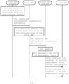
- Fig. 1 is a flowchart illustrating a method for transmitting a neighbor cell configuration information according to an embodiment of the present disclosure.
- a first base station determines a second base station corresponding to a neighbor cell of a cell whose CSI-RS configuration is updated according to a neighboring cell relationship under a condition that the CSI-RS configuration for mobility measurement in at least one associated cell is updated.
- both the first base station and the second base station support NR (New Radio), and there is no interface for direct communication between the first base station and the second base station.
- NR New Radio
- the first base station transmits the updated CSI-RS configuration information to a selected first relay node.
- the first relay node is associated with modes of the first base station and the second base station.
- the first relay node is a first AMF (Access and Mobility Management Function) entity connected to the first base station under a condition that the first base station and the second base station are both in an SA mode.
- AMF Access and Mobility Management Function
- the first relay node is a third base station having a direct communication interface with the first base station under a condition that the first base station is in a NSA mode, and the third base station supports an air interface of the LTE (long term evolution).
- LTE long term evolution
- the CSI-RS configuration information comprises at least one of the following:
- step 103 the first relay node transmits the updated CSI-RS configuration information to the second base station.
- the second base station indicates the terminal located in the coverage of the second base station to perform corresponding measurement on a cell associated with the first base station according to the updated CSI-RS configuration information.
- the updated CSI-RS configuration information is transmitted from the first base station to the second base station by using the first relay node.
- the present disclosure can effectively reduce the workload of manual configuration and reduce the possibility of configuration errors. Furthermore, the present disclosure can utilize existing protocol processes without requiring extensive modifications to existing protocols.
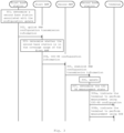
- Fig. 2 is a flowchart illustrating a method for transmitting a neighbor cell configuration information according to another embodiment of the disclosure.
- the first base station and the second base station both support the NR, and there is no interface for direct communication between the first base station and the second base station, and both the first base station and the second base station are in an SA mode.
- a first base station determines a second base station corresponding to a neighbor cell of a cell whose CSI-RS configuration is updated according to a neighboring cell relationship under a condition that the CSI-RS configuration for mobility measurement in at least one associated cell is updated.
- the first base station transmits an Uplink RAN (Radio Access Network) Configuration Transfer information to the first AMF by using an interface (for example, an NG interface) between the first base station and the first AMF.
- an interface for example, an NG interface
- the first AMF connected to the first base station is used as the first relay node.
- At least a first base station identifier and a TAI (Tracking Area identifier) corresponding to the first base station identifier, a second base station identifier and a TAI corresponding to the second base station identifier, and updated CSI-RS Configuration information are included in a SON (Self-Organized Network) Configuration Transfer information element (SON Configuration Transfer IE) of the uplink RAN Configuration Transfer information.
- SON Self-Organized Network
- the first AMF determines whether the second base station is located in the coverage of the first AMF according to the second base station identifier and the TAI corresponding to the second base station identifier.
- the first AMF transmits the updated CSI-RS Configuration information to the second base station by using a Downlink RAN Configuration transmission information under a condition that the second base station is located within the coverage of the first AMF.
- the second base station updates a current CSI-RS configuration information of a cell whose CSI-RS configuration is updated in a neighbor cell list by using the updated CSI-RS configuration information and the first base station identifier.
- the neighbor cell list includes at least one of the following:
- step 206 the second base station determines whether the CSI-RS measurement is in an on state by using the updated CSI-RS configuration information.
- the second base station indicates the terminal within the coverage of the second base station to measure the cell associated with the first base station by using the CSI-RS by using a RRC (Radio Resource Control) reconfiguration information.
- RRC Radio Resource Control
- step 207b under a condition that the CSI-RS measurement is in the off state, the second base station indicates the terminal within the coverage of the second base station to measure the cell associated with the first base station by using the SSB through the RRC reconfiguration information.
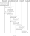
- Fig. 3 is a flowchart illustrating a method for transmitting a neighbor cell configuration information according to another embodiment of the disclosure.
- the first base station and the second base station both support the NR, and have no interface for direct communication therebetween, and both the first base station and the second base station are in an SA mode.
- a first base station determines a second base station corresponding to a neighbor cell of a cell whose CSI-RS configuration is updated according to a neighboring cell relationship under a condition that the CSI-RS configuration for mobility measurement in at least one associated cell is updated.
- the first base station transmits a uplink RAN configuration transfer information to the first AMF using an interface (e.g., an NG interface) between the first base station and the first AMF.
- an interface e.g., an NG interface
- the first AMF connected to the first base station is used as the first relay node.
- At least the first base station identifier and the TAI associated with the first base station identifier, the second base station identifier and the TAI associated with the second base station identifier, and the updated CSI-RS configuration information are included in a SON configuration transmission information element of the uplink RAN configuration transmission information.
- the first AMF determines whether the second base station is located within the coverage of the first AMF according to the second base station identifier and the TAI associated with the second base station identifier.
- the first AMF transmits the updated CSI-RS configuration information to the second AMF according to the TAI associated with the second base station identifier under a condition that the second base station is not located in the coverage of the first AMF.
- the second AMF connected to the second base station is used as the second relay node.
- the second AMF transmits the updated CSI-RS configuration information to the second base station by using the downlink RAN configuration transmission information.
- the second base station updates a current CSI-RS configuration information of a cell whose CSI-RS configuration is updated in a neighbor cell list by using the updated CSI-RS configuration information and the first base station identifier.
- step 307 the second base station determines whether the CSI-RS measurement is in an on state by using the updated CSI-RS configuration information.
- step 308a under a condition that the CSI-RS measurement is in the on state, the second base station indicates, by means of the RRC reconfiguration information, the terminal within the coverage of the second base station to measure the cell associated with the first base station by using the CSI-RS.
- step 308b under a condition that the CSI-RS measurement is in the off state, the second base station indicates, by means of the RRC reconfiguration information, the terminal within the coverage of the second base station to measure the cell associated with the first base station by using the SSB.
- Fig. 4 is a flowchart illustrating a method for transmitting a neighbor cell configuration information according to another embodiment of the disclosure.
- the first base station and the second base station both support the NR, and there is no interface for direct communication between them, and the first base station is in the NSA mode.
- a first base station determines a second base station corresponding to a neighbor cell of a cell whose CSI-RS configuration is updated according to a neighboring cell relationship under a condition that the CSI-RS configuration for mobility measurement in at least one associated cell is updated.
- the first base station transmits the updated CSI-RS Configuration information to the first LTE base station by using the EN-DC (EUTRAN-NR DC) configuration update information.
- the first LTE base station having a direct communication interface connection with the first base station is used as the first relay node.
- the first LTE base station updates the corresponding neighbor list with the updated CSI-RS configuration information.
- step 404 the first LTE base station sends an EN-DC Configuration update ACK (acknowledgement) information to the first base station.
- EN-DC Configuration update ACK acknowledgement
- the first LTE base station determines whether the second base station is located within the coverage of the first LTE base station. If the second base station is located in the coverage of the first LTE base station, the first LTE base station further determines whether the second base station supports the preset signaling radio bearer measurement according to network management configuration.
- the preset signaling radio bearer measurement is SRB (signaling Radio Bearer) 3.
- step 406 under a condition that the second base station supports the preset signaling radio bearer measurement, the first LTE base station transmits the updated CSI-RS configuration information to the second base station by means of the EN-DC configuration update information.
- the first LTE base station discards the updated CSI-RS configuration information and does not perform the subsequent processing.
- the second base station updates the corresponding neighbor cell list by using the updated CSI-RS configuration information after receiving the EN-DC configuration update information.
- step 408 the second base station transmits an EN-DC configuration update acknowledge message to the first LTE base station.
- the second base station indicates the NSA terminal located within the coverage of the second base station to perform CSI-RS measurement for a cell supporting CSI-RS measurement among cells associated with the first base station.
- Fig. 5 is a flowchart illustrating a method for transmitting neighbor cell configuration information according to another embodiment of the disclosure.
- the first base station and the second base station both support the NR, and there is no interface for direct communication between them, and the first base station is in the NSA mode.
- a first base station determines a second base station corresponding to a neighbor cell of a cell whose CSI-RS configuration is updated according to a neighboring cell relationship under a condition that the CSI-RS configuration for mobility measurement in at least one associated cell is updated.
- the first base station transmits the updated CSI-RS Configuration information to the first LTE base station by using the EN-DC configuration update information.
- the first LTE base station having a direct communication interface connection with the first base station is used as the first relay node.
- the first LTE base station updates the corresponding neighbor cell list with the updated CSI-RS configuration information.
- step 504 the first LTE base station transmits an EN-DC configuration update acknowledge message to the first base station.
- step 505 the first LTE base station determines whether the second base station is located within the coverage of the first LTE base station.
- the first relay node transmits the updated CSI-RS configuration information to the second LTE base station through an eNB (Evolved NodeB) configuration update information.
- the second LTE base station having a direct communication interface with the second base station is used as the second relay node.
- the second relay node supports an air interface of the LTE, and the second base station is located in the coverage range of the second relay node.
- the second LTE base station updates the corresponding neighbor cell list with the updated CSI-RS configuration information.
- the second LTE base station transmits the eNB configuration update confirmation information to the first LTE base station.
- the second LTE base station determines whether the second base station supports the preset signaling radio bearer measurement according to the network management configuration.
- the preset signaling radio bearer measurement is SRB3.
- step 510 under a condition that the second base station supports the predetermined signaling radio bearer measurement, the second LTE base station transmits the updated CSI-RS configuration information to the second base station through the EN-DC configuration update information.
- the second LTE base station under a condition that the second base station does not support the predetermined signaling radio bearer measurement, discards the updated CSI-RS configuration information and does not perform the subsequent processing.
- the second base station updates the corresponding neighbor cell list by using the updated CSI-RS configuration information after receiving the EN-DC configuration update information.
- step 512 the second base station transmits an EN-DC configuration update confirmation information to the second LTE base station.
- the second base station indicates the NSA terminal within the coverage of the second base station to perform CSI-RS measurement for a cell supporting CSI-RS measurement among cells associated with the first base station.
- Fig. 6 is a schematic structural diagram of a neighbor cell configuration information transmission system according to an embodiment of the present disclosure. As shown in Fig. 6 , the system includes a first base station 61, a second base station 62, and a first relay node 63. The first base station 61 and the second base station 62 both support the NR, and there is no interface for direct communication between the first base station 61 and the second base station 62.
- the first base station 61 determines a second base station 62 corresponding to a neighbor cell of a cell whose CSI-RS configuration is updated according to a neighboring cell relationship under a condition that the CSI-RS configuration for mobility measurement in at least one associated cell is updated.
- the first base station 61 transmits the updated CSI-RS configuration information to the selected first relay node 63.
- the first relay node 63 is associated with modes of the first base station 61 and the second base station 62.
- the first relay node 63 is a first AMF entity connected to the first base station 61 under a condition that the first base station 61 and the second base station 62 are both in an SA mode.
- the first relay node 63 is a third base station having a direct communication interface with the first base station 61 under a condition that the first base station 61 is in a NSA mode, wherein the third base station supports an air interface of the LTE.
- the CSI-RS configuration information comprises at least one of the following:
- the first relay node 63 transmits the updated CSI-RS configuration information to the second base station 62.
- the second base station 62 indicates the terminal in the coverage of the second base station 62 to perform corresponding measurements on the cell associated with the first base station 61 according to the updated CSI-RS configuration information.
- the first base station 611 transmits the uplink RAN configuration transmission information to the first relay node 63 using an interface (for example, an NG interface) between the first base station and the first relay node 63.
- an interface for example, an NG interface
- the SON configuration transmission information element in the uplink RAN configuration transmission information contains a first base station identifier and a tracking area identifier corresponding to the first base station identifier, a second base station identifier and a tracking area identifier corresponding to the second base station identifier, and updated CSI-RS configuration information.
- the first relay node 63 determines whether the second base station 62 is located within the coverage of the first relay node 63 according to the second base station identifier and the tracking area identifier corresponding to the second base station identifier. Under a condition that the second base station 62 is located within the coverage of the first relay node 63, the first relay node 63 transmits the updated CSI-RS configuration information to the second base station 62 by using the downlink RAN configuration transmission information.
- the second base station 62 updates a current CSI-RS configuration information of a cell whose CSI-RS configuration is updated in a neighbor cell list by using the updated CSI-RS configuration information and the first base station identifier.
- the neighbor cell list includes at least one of a first base station identifier, a cell identifier of a cell whose CSI-RS configuration is updated, a mode of the first base station, an indicating information of whether a direct connection interface exists with the first base station, an indicating information of whether to enable CSI-RS measurement, and a CSI-RS configuration information.
- the second base station 62 determines whether the CSI-RS measurement is in an on state by using the updated CSI-RS configuration information. Under a condition that the CSI-RS measurement is in the on state, the second base station 62 indicates, through the RRC reconfiguration information, the terminal within the coverage of the second base station 62 to measure the cell associated with the first base station by using the CSI-RS. Under a condition that the CSI-RS measurement is in the off state, the second base station 62 indicates, through the RRC reconfiguration information, the terminal within the coverage of the second base station 62 to measure the cell associated with the first base station by using the SSB.
- Fig. 7 is a schematic structural diagram of a neighboring cell configuration information transmission system according to another embodiment of the present disclosure.
- Fig. 7 differs from Fig. 6 in that, in the embodiment shown in Fig. 7 , the first relay node 63 is further configured to send the updated CSI-RS configuration information to the second relay node 64 under a condition that the second base station 62 is not located in the coverage of the first relay node 63.
- the second relay node 64 is a second AMF connected to the second base station 62.
- the second relay node 64 transmits the updated CSI-RS configuration information to the second base station using the downlink RAN configuration transmission information.
- a third base station having a direct communication interface connection with the first base station 61 is used as the first relay node 63, where the third base station supports an LTE air interface.
- the first base station 61 transmits the updated CSI-RS configuration information to the first relay node 63 through the EN-DC configuration update information.
- the first relay node 63 updates the corresponding neighbor cell list by using the updated CSI-RS configuration information, and sends an EN-DC configuration update acknowledge message to the first base station 61.
- the first relay node 63 determines whether the second base station 62 is within the coverage of the first relay node 63.
- the first relay node 63 determines whether the second base station 62 supports the preset signaling radio bearer measurement, and under a condition that the second base station 62 supports the preset signaling radio bearer measurement, the first relay node 63 transmits the updated CSI-RS configuration information to the second base station 62 through the EN-DC configuration update information.
- the preset signaling radio bearer measurement is SRB3.
- the second base station 62 After receiving the EN-DC configuration update information, the second base station 62 updates the corresponding neighbor cell list by using the updated CSI-RS configuration information, and transmits an EN-DC configuration update acknowledge message to the first relay node 63.
- the second base station 62 indicates the NSA terminal within the coverage of the second base station 62 to perform CSI-RS measurement for a cell supporting CSI-RS measurement among cells associated with the first base station under a condition that the first base station starts CSI-RS measurement.
- the first relay node 63 discards the updated CSI-RS configuration information under a condition that the second base station 62 does not support the preset signaling radio bearer measurement.
- the first relay node 63 transmits the updated CSI-RS configuration information to the second relay node 64 through the eNB configuration update information under a condition that the second base station 62 is not located in the coverage of the first relay node 63, as shown in Fig. 7 .
- the second relay node 64 supports LTE air interfaces, and the second base station 62 is located within the coverage of the second relay node 64.
- the second relay node 64 updates the corresponding neighbor cell list by using the updated CSI-RS configuration information, and transmits an eNB configuration update acknowledge information to the first relay node.
- the second relay node 64 determines whether the second base station 62 supports the preset signaling radio bearer measurement, and if the second base station 62 supports the preset signaling radio bearer measurement, the second relay node 64 transmits the updated CSI-RS configuration information to the second base station 62 through the EN-DC configuration update information.
- the second base station 62 updates the corresponding neighbor cell list by using the updated CSI-RS configuration information, and transmits an EN-DC configuration update acknowledge message to the second relay node 64.
- the second base station 62 indicates the NSA terminal in the coverage of the second base station 62 to perform CSI-RS measurement for a cell supporting CSI-RS measurement among cells associated with the first base station under a condition that the first base station 61 starts CSI-RS measurement.
- the second relay node 64 discards the updated CSI-RS configuration information under a condition that the second base station 62 does not support the preset signaling radio bearer measurement.
- the present disclosure also provides a computer-readable storage medium.
- the computer readable storage medium stores computer instructions which, when executed by the processor, implement the method according to any one of Fig. 1 to 5 .
- NR base stations there are two NR base stations within the coverage of LTE base station 1, which are NR base station 1 and NR base station 2, respectively.
- the NR base station 1 and NR base station 2 are configured with CSI-RS configuration information for mobility measurement.
- the NSA terminal 1 is located within the coverage of the NR base station 2. This embodiment describes a process in which the NR base station 2 configures CSI-RS measurement for the NSA terminal 1 after the CSI-RS configuration of the NR base station 1 is updated.
- Step 1 the NR base station 1 updates CSI-RS configuration information. Since the NR base station 1 and the peripheral NR base stations do not have a direct connection interface and the NR base station 1 is in a NSA mode, the NR base station 1 transmits the updated CSI-RS configuration information to the LTE base station 1 by using an EN-DC configuration update information.
- Step 2 after receiving the EN-DC configuration update information, the LTE base station 1 stores the CSI-RS configuration information of the relevant cells in the NR base station 1.
- Step 3 the LTE base station 1 transmits an EN-DC configuration update acknowledge message to the NR base station 1.
- Step 4 since the NR base station 2 supports SRB3, the LTE base station 1 transmits the updated CSI-RS configuration information of the NR base station 1 to the NR base station 2 through the EN-DC configuration update information.
- Step 5 the NR base station 2 saves the updated CSI-RS configuration information of the base station 1, and transmits the updated CSI-RS configuration information of the NR base station 1 to the NR base station 1 by using the EN-DC configuration update confirm message.
- Step 6 the NR base station 1 performs CSI-RS measurement configuration for the NSA terminal 1, wherein the measurement configuration includes identifiers of cells related to the NR base station 1 and the NR base station 2 and configuration information of the CSI-RS.
- Step 7 the NSA terminal 1 transmits the measurement result on the NR base station 1 to the NR base station 2 by using the SRB3 according to the measurement result.
- NR base station 1 in the coverage of the LTE base station 1, and an NR base station 2 in the coverage of the LTE base station 2.
- the NR base station 1 and the NR base station 2 are configured with CSI-RS configuration information for mobility measurements.
- the NSA terminal 1 is located within the coverage of the NR base station 2. This embodiment describes a process in which the NR base station 2 configures CSI-RS measurement for the NSA terminal 1 after the CSI-RS configuration of the NR base station 1 is updated.
- Step 1 the NR base station 1 updates a CSI-RS configuration information.
- the NR base station 1 and peripheral NR base stations do not have direct connection interfaces, and the NR base station 1 is in an NSA mode, and the NR base station 1 transmits an updated CSI-RS configuration information to the LTE base station 1 by using an EN-DC configuration updating message.
- Step 2 after receiving the EN-DC configuration updating message, the LTE base station 1 stores the CSI-RS configuration information of the relevant cells in the NR base station 1.
- Step 3 the LTE base station 1 transmits an EN-DC configuration update acknowledge message to the NR base station 1.
- Step 4 the LTE base station 1 transmits the updated CSI-RS configuration information to the LTE base station 2 through an eNB configuration updating message.
- Step 5 the LTE base station 2 saves the CSI-RS configuration of the NR base station 1 and transmits an eNB configuration update acknowledge message to the LTE base station 1.
- Step 6 since the NR base station 2 supports SRB3, the LTE base station 2 transmits the updated CSI-RS configuration information of the NR base station 1 to the NR base station 2 by means of the EN-DC configuration updating message.
- Step 7 the NR base station 2 saves CSI-RS configuration information of the NR base station 1, and transmits an EN-DC configuration update acknowledge message to the LTE base station 2.
- Step 8 the NR base station 2 performs CSI-RS measurement configuration for the NSA terminal 1, wherein the measurement configuration includes identifiers of cells related to the NR base station 1 and the NR base station 2 and CSI-RS configuration information.
- Step 9 according to the measurement results, the NSA terminal 1 transmits the measurement result regarding the NR base station 1 to the NR base station 2 by using the SRB3.
- NR base station 1 and NR base station 2 are connected by AMF, respectively.
- the CSI-RS measurement configuration of the NR base station 1 has been turned off for energy-saving reasons, and the NR base station 1 triggers CSI-RS configuration updating, and informs the NR base station 2 of changing strategies through AMF.
- the NR base station 2 after receiving the notification, adopts the SSB-based measurement scheme for all users.
- Step 1 the NR base station 1 turns off the CSI-RS transmission and updates CSI-RS configuration information because there is no terminal connected in the coverage area.
- the NR base station 1 selects an AMF as a relay node because there is no direct connection interface between the NR base station 1 and the peripheral NR base stations and the NR base station 1 is in an SA mode.
- Step 2 the NR base station 1 transmits an uplink RAN configuration transfer information to the AMF connected to the NR base station 1 using an NG interface, wherein the following information is included:
- Step 3 after receiving the uplink RAN configuration transmission information, the AMF determines that the base station 2 is located within the coverage of the AMF according to the TAI of the NR base station 2.
- the AMF transmits an downlink RAN configuration transfer information to the NR base station 2, so as to send CSI-RS configuration information to the NR base station 2.
- Step 4 the NR base station 2 saves the CSI-RS configuration information. Since the CSI-RS configuration information only includes a cell identifier, the NR base station 2 deletes the CSI-RS configuration information of the cell related to the NR base station 1.
- Step 5 the NR base station 2 triggers the terminals 1 within its coverage to make relevant measurements on the NR base station 1 by using the SSB.
- the functional unit modules described above can be implemented as a general purpose Processor, a Programmable Logic Controller (PLC), a Digital Signal Processor (Digital Signal Processor, DSP), an Application Specific Integrated Circuit (ASIC), a Field Programmable Gate Array (FPGA) or other Programmable Logic device, discrete Gate or transistor Logic, discrete hardware components, or any suitable combination thereof for performing the functions described in this disclosure.
- PLC Programmable Logic Controller
- DSP Digital Signal Processor
- ASIC Application Specific Integrated Circuit
- FPGA Field Programmable Gate Array
- other Programmable Logic device discrete Gate or transistor Logic, discrete hardware components, or any suitable combination thereof for performing the functions described in this disclosure.
Landscapes
- Engineering & Computer Science (AREA)
- Signal Processing (AREA)
- Computer Networks & Wireless Communication (AREA)
- Computer Security & Cryptography (AREA)
- Mobile Radio Communication Systems (AREA)
Description
- The present application is based on and claims priority from
CN application No. 201910500450.X, filed on June 11, 2019 - The present disclosure relates to the field of wireless communications, and in particular, to a method and system for transmitting neighbor cell configuration information.
- In the related art, there are two measurement references for inter-cell handover, which are SSB (Synchronization Signal Block) based measurement and CSI (Channel State Information) -RS (Reference Signal) based measurement.
- The SSB has a frequency domain width of only 20 PRBs (Physical Resource blocks), and cannot measure the condition of the whole channel, while the CSI-RS can be configured to be full-band. In addition, the beams of the CSI-RS are narrower than the beams of the SSB, and can reflect the actual service beam condition. In some scenarios, the beamwidth of the SSB may differ significantly from that of the service beam of the user. Therefore, the measurement result based on the CSI-RS has higher accuracy than the handover based on the SSB based measurement.
- The publication HUAWAI et al "Inter node message for CSI-RS configuration, 3GPP Draft R2-1814147, vol. RAN WG2, no. Chengdu, China, 20181008-20181012 28 September 2018, discloses a method and network for transmitting cell Channel State Information Reference Signal (CSI-RS) resource configuration information of neighbor cell for subsequent L3 mobility.
- The publication HUAWEI et al " Avoiding Mobility Failures due to Slice Availability " 3GPP DRAFT R3-192962, vol. RAN WG3, no. Reno, Nevada, USA, 20190513-20190517 4 May 2019, is a discussion upon solutions to avoid intra-system mobility failures due to slice availability.
- Aspects of the present invention are provided in the independent claims and further detailed in the dependent claims.
- Other features of the present disclosure and advantages thereof will become apparent from the following detailed description of exemplary embodiments thereof, which proceeds with reference to the accompanying drawings. The scope of the present invention is defined by the scope of the appended claims.
- The accompanying drawings, which are incorporated in and constitute a part of this specification, illustrate embodiments of the disclosure and together with the description, serve to explain the principles of the disclosure.
- The present disclosure may be more clearly understood from the following detailed description with reference to the accompanying drawings, in which:
-
Fig. 1 is a flowchart illustrating a method for transmitting a neighbor cell configuration information according to one embodiment of the present disclosure; -
Fig. 2 is a flowchart illustrating a method for transmitting a neighbor cell configuration information according to another embodiment of the present disclosure; -
Fig. 3 is a flowchart illustrating a method for transmitting a neighbor cell configuration information according to still another embodiment of the disclosure; -
Fig. 4 is a flowchart illustrating a method for transmitting neighbor cell configuration information according to another embodiment of the disclosure; -
Fig. 5 is a flowchart illustrating a method for transmitting a neighbor cell configuration information according to still another embodiment of the disclosure; -
Fig. 6 is a schematic structural diagram of a system of transmitting a neighbor cell configuration information according to an embodiment of the present disclosure; -
Fig. 7 is a schematic structural diagram of a system of transmitting a neighbor cell configuration information according to another embodiment of the present disclosure. - It should be understood that the dimensions of the various parts shown in the drawings are not drawn to scale. Further, the same or similar reference numerals denote the same or similar component.
- The technical solutions in the embodiments of the present disclosure will be described clearly and completely with reference to the drawings in the embodiments of the present disclosure, and it is obvious that the embodiments described are only some, rather than all, of the embodiments of the present disclosure. The following description of at least one exemplary embodiment is merely illustrative in nature and is in no way intended to limit the disclosure, its application, or uses. The scope of the present invention is defined by the scope of the appended claims.
- The relative arrangement of parts and steps, numerical expressions and numerical values set forth in these embodiments do not limit the scope of the present disclosure unless specifically stated otherwise.
- Meanwhile, it should be understood that, for the convenience of description, the sizes of the respective portions shown in the drawings are not drawn in an actual proportional relationship.
- Techniques, methods, and apparatus known to one of ordinary skill in the relevant art may not be discussed in detail but are intended to be part of the specification where appropriate.
- In all examples shown and discussed herein, any particular value should be construed as exemplary only and not as limiting. Thus, other examples of the exemplary embodiments may have different values.
- It should be noted that: similar reference numbers and letters refer to similar items in the following figures, and thus, once an item is defined in one figure, it need not be discussed further in subsequent figures.
- The inventors have noticed that because the configuration of the CSI-RS information is at least one cell granularity and the CSI-RS information is a time-varying parameter, completely completing the configuration of the CSI-RS information through network management or manually leads to a large optimization workload and is prone to configuration errors. In order to reduce the error probability and improve the network automation degree, some schemes are proposed in the related art for updating based on CSI-RS. But these schemes only support SA (standalone) mode and there is a scenario of an Xn interface. Since there is no interface between base stations in an NSA (Non-Standalone) scenario, these related techniques cannot be applied to the NSA scenario.
- Therefore, the present disclosure provides a scheme for an NR base station to automatically acquire CSI-RS configuration information without an interbase station interface.
-
Fig. 1 is a flowchart illustrating a method for transmitting a neighbor cell configuration information according to an embodiment of the present disclosure. - In
step 101, a first base station determines a second base station corresponding to a neighbor cell of a cell whose CSI-RS configuration is updated according to a neighboring cell relationship under a condition that the CSI-RS configuration for mobility measurement in at least one associated cell is updated. - It should be noted that, both the first base station and the second base station support NR (New Radio), and there is no interface for direct communication between the first base station and the second base station.
- In
step 102, the first base station transmits the updated CSI-RS configuration information to a selected first relay node. - The first relay node is associated with modes of the first base station and the second base station.
- For example, the first relay node is a first AMF (Access and Mobility Management Function) entity connected to the first base station under a condition that the first base station and the second base station are both in an SA mode.
- The first relay node is a third base station having a direct communication interface with the first base station under a condition that the first base station is in a NSA mode, and the third base station supports an air interface of the LTE (long term evolution).
- In some embodiments, the CSI-RS configuration information comprises at least one of the following:
- cell identifier: for example, PCI (Physical Cell Identifier) is used for identification.
- indicating information regarding whether to turn off the CSI-RS measurement: 1-bit information may be used, wherein 1 represents the off measurement and 0 is the reserved bit. If the indicating information is not contained, the CSI-RS measurement needs to be continued.
- CSI-RS power configuration information: at least including at least one of the following:
- ✔ power with respect to PDSCH (Physical Downlink Shared Channel)
- ✔ Power offset with respect to SSS (Secondary Synchronization Signal)
- ✔ scrambling code number
- CSI-RS measurement bandwidth information: at least including at least one of the following:
- ✔ measurement bandwidth: for example, 24 PRBs, 48 PRBs, 96 PRBs, 192 PRBs, 264 PRBs
- ✔ initial PRB position of CSI-RS
- ✔ CSI-RS Density: e.g. 1 or 3
- CSI-RS beam configuration: at least including at least one of the following:
- ✔ Beam number
- ✔ subframe position where the beam exists and its cycle
- ✔ CSI-RS Generation sequence number
- ✔ initial symbol of CSI-RS in time slot
- ✔ frequency-domain pattern of CSI-RS in each PRB
- In
step 103, the first relay node transmits the updated CSI-RS configuration information to the second base station. - In
step 104, the second base station indicates the terminal located in the coverage of the second base station to perform corresponding measurement on a cell associated with the first base station according to the updated CSI-RS configuration information. - In the method for transmitting a neighbor cell configuration information provided in the foregoing embodiment of the present disclosure, under a condition that both the first base station and the second base station support the NR but have no interface for direct communication therebetween, the updated CSI-RS configuration information is transmitted from the first base station to the second base station by using the first relay node. The present disclosure can effectively reduce the workload of manual configuration and reduce the possibility of configuration errors. Furthermore, the present disclosure can utilize existing protocol processes without requiring extensive modifications to existing protocols.
-
Fig. 2 is a flowchart illustrating a method for transmitting a neighbor cell configuration information according to another embodiment of the disclosure. In the embodiment shown inFig. 2 , the first base station and the second base station both support the NR, and there is no interface for direct communication between the first base station and the second base station, and both the first base station and the second base station are in an SA mode. - In step 201, a first base station determines a second base station corresponding to a neighbor cell of a cell whose CSI-RS configuration is updated according to a neighboring cell relationship under a condition that the CSI-RS configuration for mobility measurement in at least one associated cell is updated.
- In
step 202, the first base station transmits an Uplink RAN (Radio Access Network) Configuration Transfer information to the first AMF by using an interface (for example, an NG interface) between the first base station and the first AMF. Here, the first AMF connected to the first base station is used as the first relay node. - In some embodiments, at least a first base station identifier and a TAI (Tracking Area identifier) corresponding to the first base station identifier, a second base station identifier and a TAI corresponding to the second base station identifier, and updated CSI-RS Configuration information are included in a SON (Self-Organized Network) Configuration Transfer information element (SON Configuration Transfer IE) of the uplink RAN Configuration Transfer information.
- In
step 203, the first AMF determines whether the second base station is located in the coverage of the first AMF according to the second base station identifier and the TAI corresponding to the second base station identifier. - In step 204, the first AMF transmits the updated CSI-RS Configuration information to the second base station by using a Downlink RAN Configuration transmission information under a condition that the second base station is located within the coverage of the first AMF.
- In
step 205, the second base station updates a current CSI-RS configuration information of a cell whose CSI-RS configuration is updated in a neighbor cell list by using the updated CSI-RS configuration information and the first base station identifier. - In some embodiments, the neighbor cell list includes at least one of the following:
- a base station identifier of first base station;
- a cell identifier of the cell whose CSI-RS configuration is updated;
- mode of the first base station: for example, NSA, SA or dual mode;
- indicating information regarding whether a direct connection interface exists with a first base station
- indicating information regarding whether to enable CSI-RS measurement;
- CSI-RS configuration information.
- In
step 206, the second base station determines whether the CSI-RS measurement is in an on state by using the updated CSI-RS configuration information. - In step 207a, under a condition that the CSI-RS measurement is in an on state, the second base station indicates the terminal within the coverage of the second base station to measure the cell associated with the first base station by using the CSI-RS by using a RRC (Radio Resource Control) reconfiguration information.
- In step 207b, under a condition that the CSI-RS measurement is in the off state, the second base station indicates the terminal within the coverage of the second base station to measure the cell associated with the first base station by using the SSB through the RRC reconfiguration information.
-
Fig. 3 is a flowchart illustrating a method for transmitting a neighbor cell configuration information according to another embodiment of the disclosure. In the embodiment shown inFig. 3 , the first base station and the second base station both support the NR, and have no interface for direct communication therebetween, and both the first base station and the second base station are in an SA mode. - In
step 301, a first base station determines a second base station corresponding to a neighbor cell of a cell whose CSI-RS configuration is updated according to a neighboring cell relationship under a condition that the CSI-RS configuration for mobility measurement in at least one associated cell is updated. - At
step 302, the first base station transmits a uplink RAN configuration transfer information to the first AMF using an interface (e.g., an NG interface) between the first base station and the first AMF. Here, the first AMF connected to the first base station is used as the first relay node. - In some embodiments, at least the first base station identifier and the TAI associated with the first base station identifier, the second base station identifier and the TAI associated with the second base station identifier, and the updated CSI-RS configuration information are included in a SON configuration transmission information element of the uplink RAN configuration transmission information.
- In
step 303, the first AMF determines whether the second base station is located within the coverage of the first AMF according to the second base station identifier and the TAI associated with the second base station identifier. - In step 304, the first AMF transmits the updated CSI-RS configuration information to the second AMF according to the TAI associated with the second base station identifier under a condition that the second base station is not located in the coverage of the first AMF. Here, the second AMF connected to the second base station is used as the second relay node.
- In
step 305, the second AMF transmits the updated CSI-RS configuration information to the second base station by using the downlink RAN configuration transmission information. - In
step 306, the second base station updates a current CSI-RS configuration information of a cell whose CSI-RS configuration is updated in a neighbor cell list by using the updated CSI-RS configuration information and the first base station identifier. - In
step 307, the second base station determines whether the CSI-RS measurement is in an on state by using the updated CSI-RS configuration information. - In step 308a, under a condition that the CSI-RS measurement is in the on state, the second base station indicates, by means of the RRC reconfiguration information, the terminal within the coverage of the second base station to measure the cell associated with the first base station by using the CSI-RS.
- In step 308b, under a condition that the CSI-RS measurement is in the off state, the second base station indicates, by means of the RRC reconfiguration information, the terminal within the coverage of the second base station to measure the cell associated with the first base station by using the SSB.
-
Fig. 4 is a flowchart illustrating a method for transmitting a neighbor cell configuration information according to another embodiment of the disclosure. In the embodiment shown inFig. 4 , the first base station and the second base station both support the NR, and there is no interface for direct communication between them, and the first base station is in the NSA mode. - In
step 401, a first base station determines a second base station corresponding to a neighbor cell of a cell whose CSI-RS configuration is updated according to a neighboring cell relationship under a condition that the CSI-RS configuration for mobility measurement in at least one associated cell is updated. - In step 402, the first base station transmits the updated CSI-RS Configuration information to the first LTE base station by using the EN-DC (EUTRAN-NR DC) configuration update information. Here, the first LTE base station having a direct communication interface connection with the first base station is used as the first relay node.
- In
step 403, the first LTE base station updates the corresponding neighbor list with the updated CSI-RS configuration information. - In step 404, the first LTE base station sends an EN-DC Configuration update ACK (acknowledgement) information to the first base station.
- In
step 405, the first LTE base station determines whether the second base station is located within the coverage of the first LTE base station. If the second base station is located in the coverage of the first LTE base station, the first LTE base station further determines whether the second base station supports the preset signaling radio bearer measurement according to network management configuration. - In some embodiments, the preset signaling radio bearer measurement is SRB (signaling Radio Bearer) 3.
- In step 406, under a condition that the second base station supports the preset signaling radio bearer measurement, the first LTE base station transmits the updated CSI-RS configuration information to the second base station by means of the EN-DC configuration update information.
- In some embodiments, under a condition that the second base station does not support the preset signaling radio bearer measurement, the first LTE base station discards the updated CSI-RS configuration information and does not perform the subsequent processing.
- In
step 407, the second base station updates the corresponding neighbor cell list by using the updated CSI-RS configuration information after receiving the EN-DC configuration update information. - In step 408, the second base station transmits an EN-DC configuration update acknowledge message to the first LTE base station.
- In
step 409, under a condition that the first base station starts CSI-RS measurement, the second base station indicates the NSA terminal located within the coverage of the second base station to perform CSI-RS measurement for a cell supporting CSI-RS measurement among cells associated with the first base station. -
Fig. 5 is a flowchart illustrating a method for transmitting neighbor cell configuration information according to another embodiment of the disclosure. In the embodiment shown inFig. 5 , the first base station and the second base station both support the NR, and there is no interface for direct communication between them, and the first base station is in the NSA mode. - In
step 501, a first base station determines a second base station corresponding to a neighbor cell of a cell whose CSI-RS configuration is updated according to a neighboring cell relationship under a condition that the CSI-RS configuration for mobility measurement in at least one associated cell is updated. - In step 502, the first base station transmits the updated CSI-RS Configuration information to the first LTE base station by using the EN-DC configuration update information. Here, the first LTE base station having a direct communication interface connection with the first base station is used as the first relay node.
- In
step 503, the first LTE base station updates the corresponding neighbor cell list with the updated CSI-RS configuration information. - In step 504, the first LTE base station transmits an EN-DC configuration update acknowledge message to the first base station.
- In
step 505, the first LTE base station determines whether the second base station is located within the coverage of the first LTE base station. - In step 506, under a condition that the second base station is not located in the coverage of the first relay node, the first relay node transmits the updated CSI-RS configuration information to the second LTE base station through an eNB (Evolved NodeB) configuration update information. Here, the second LTE base station having a direct communication interface with the second base station is used as the second relay node. The second relay node supports an air interface of the LTE, and the second base station is located in the coverage range of the second relay node.
- In
step 507, the second LTE base station updates the corresponding neighbor cell list with the updated CSI-RS configuration information. - In step 508, the second LTE base station transmits the eNB configuration update confirmation information to the first LTE base station.
- In
step 509, the second LTE base station determines whether the second base station supports the preset signaling radio bearer measurement according to the network management configuration. - In some embodiments, the preset signaling radio bearer measurement is SRB3.
- In step 510, under a condition that the second base station supports the predetermined signaling radio bearer measurement, the second LTE base station transmits the updated CSI-RS configuration information to the second base station through the EN-DC configuration update information.
- In some embodiments, under a condition that the second base station does not support the predetermined signaling radio bearer measurement, the second LTE base station discards the updated CSI-RS configuration information and does not perform the subsequent processing.
- In
step 511, the second base station updates the corresponding neighbor cell list by using the updated CSI-RS configuration information after receiving the EN-DC configuration update information. - In step 512, the second base station transmits an EN-DC configuration update confirmation information to the second LTE base station.
- In
step 513, under a condition that the first base station starts CSI-RS measurement, the second base station indicates the NSA terminal within the coverage of the second base station to perform CSI-RS measurement for a cell supporting CSI-RS measurement among cells associated with the first base station. -
Fig. 6 is a schematic structural diagram of a neighbor cell configuration information transmission system according to an embodiment of the present disclosure. As shown inFig. 6 , the system includes afirst base station 61, asecond base station 62, and afirst relay node 63. Thefirst base station 61 and thesecond base station 62 both support the NR, and there is no interface for direct communication between thefirst base station 61 and thesecond base station 62. - The
first base station 61 determines asecond base station 62 corresponding to a neighbor cell of a cell whose CSI-RS configuration is updated according to a neighboring cell relationship under a condition that the CSI-RS configuration for mobility measurement in at least one associated cell is updated. Thefirst base station 61 transmits the updated CSI-RS configuration information to the selectedfirst relay node 63. - The
first relay node 63 is associated with modes of thefirst base station 61 and thesecond base station 62. - For example, the
first relay node 63 is a first AMF entity connected to thefirst base station 61 under a condition that thefirst base station 61 and thesecond base station 62 are both in an SA mode. - The
first relay node 63 is a third base station having a direct communication interface with thefirst base station 61 under a condition that thefirst base station 61 is in a NSA mode, wherein the third base station supports an air interface of the LTE. - In some embodiments, the CSI-RS configuration information comprises at least one of the following:
- cell identifier: for example, PCI (Physical Cell Identifier) is used for identification.
- indicating information regarding whether to turn off the CSI-RS measurement: 1-bit information may be used, wherein 1 represents the off measurement and 0 is the reserved bit. If the indicating information is not contained, the CSI-RS measurement needs to be continued.
- CSI-RS power configuration information: at least including at least one of the following:
- ✔ power with respect to PDSCH (Physical Downlink Shared Channel)
- ✔ Power offset with respect to SSS (Secondary Synchronization Signal)
- ✔ scrambling code number
- CSI-RS measurement bandwidth information: at least including at least one of the following:
- ✔ measurement bandwidth: for example, 24 PRBs, 48 PRBs, 96 PRBs, 192 PRBs, 264 PRBs
- ✔ initial PRB position of CSI-RS
- ✔ CSI-RS Density: e.g. 1 or 3
- CSI-RS beam configuration: at least including at least one of the following:
- ✔ Beam number
- ✔ subframe position where the beam exists and its cycle
- ✔ CSI-RS Generation sequence number
- ✔ initial symbol of CSI-RS in time slot
- ✔ frequency-domain pattern of CSI-RS in each PRB
- The
first relay node 63 transmits the updated CSI-RS configuration information to thesecond base station 62. Thesecond base station 62 indicates the terminal in the coverage of thesecond base station 62 to perform corresponding measurements on the cell associated with thefirst base station 61 according to the updated CSI-RS configuration information. - In some embodiments, under a condition that the
first base station 61 and thesecond base station 62 are both in the SA mode, and the first AMF connected to thefirst base station 61 is used as thefirst relay node 63, the first base station 611 transmits the uplink RAN configuration transmission information to thefirst relay node 63 using an interface (for example, an NG interface) between the first base station and thefirst relay node 63. - For example, the SON configuration transmission information element in the uplink RAN configuration transmission information contains a first base station identifier and a tracking area identifier corresponding to the first base station identifier, a second base station identifier and a tracking area identifier corresponding to the second base station identifier, and updated CSI-RS configuration information.
- The
first relay node 63 determines whether thesecond base station 62 is located within the coverage of thefirst relay node 63 according to the second base station identifier and the tracking area identifier corresponding to the second base station identifier. Under a condition that thesecond base station 62 is located within the coverage of thefirst relay node 63, thefirst relay node 63 transmits the updated CSI-RS configuration information to thesecond base station 62 by using the downlink RAN configuration transmission information. - The
second base station 62 updates a current CSI-RS configuration information of a cell whose CSI-RS configuration is updated in a neighbor cell list by using the updated CSI-RS configuration information and the first base station identifier. - In some embodiments, the neighbor cell list includes at least one of a first base station identifier, a cell identifier of a cell whose CSI-RS configuration is updated, a mode of the first base station, an indicating information of whether a direct connection interface exists with the first base station, an indicating information of whether to enable CSI-RS measurement, and a CSI-RS configuration information.
- In some embodiments, the
second base station 62 determines whether the CSI-RS measurement is in an on state by using the updated CSI-RS configuration information. Under a condition that the CSI-RS measurement is in the on state, thesecond base station 62 indicates, through the RRC reconfiguration information, the terminal within the coverage of thesecond base station 62 to measure the cell associated with the first base station by using the CSI-RS. Under a condition that the CSI-RS measurement is in the off state, thesecond base station 62 indicates, through the RRC reconfiguration information, the terminal within the coverage of thesecond base station 62 to measure the cell associated with the first base station by using the SSB. -
Fig. 7 is a schematic structural diagram of a neighboring cell configuration information transmission system according to another embodiment of the present disclosure. -
Fig. 7 differs fromFig. 6 in that, in the embodiment shown inFig. 7 , thefirst relay node 63 is further configured to send the updated CSI-RS configuration information to thesecond relay node 64 under a condition that thesecond base station 62 is not located in the coverage of thefirst relay node 63. Thesecond relay node 64 is a second AMF connected to thesecond base station 62. Thesecond relay node 64 transmits the updated CSI-RS configuration information to the second base station using the downlink RAN configuration transmission information. - In some embodiments, as shown in
Fig. 6 , when thefirst base station 61 is in the NSA mode, a third base station having a direct communication interface connection with thefirst base station 61 is used as thefirst relay node 63, where the third base station supports an LTE air interface. - The
first base station 61 transmits the updated CSI-RS configuration information to thefirst relay node 63 through the EN-DC configuration update information. Thefirst relay node 63 updates the corresponding neighbor cell list by using the updated CSI-RS configuration information, and sends an EN-DC configuration update acknowledge message to thefirst base station 61. Thefirst relay node 63 determines whether thesecond base station 62 is within the coverage of thefirst relay node 63. Under a condition that thesecond base station 62 is located in the coverage of thefirst relay node 63, thefirst relay node 63 determines whether thesecond base station 62 supports the preset signaling radio bearer measurement, and under a condition that thesecond base station 62 supports the preset signaling radio bearer measurement, thefirst relay node 63 transmits the updated CSI-RS configuration information to thesecond base station 62 through the EN-DC configuration update information. - In some embodiments, the preset signaling radio bearer measurement is SRB3.
- After receiving the EN-DC configuration update information, the
second base station 62 updates the corresponding neighbor cell list by using the updated CSI-RS configuration information, and transmits an EN-DC configuration update acknowledge message to thefirst relay node 63. Thesecond base station 62 indicates the NSA terminal within the coverage of thesecond base station 62 to perform CSI-RS measurement for a cell supporting CSI-RS measurement among cells associated with the first base station under a condition that the first base station starts CSI-RS measurement. - In some embodiments, the
first relay node 63 discards the updated CSI-RS configuration information under a condition that thesecond base station 62 does not support the preset signaling radio bearer measurement. - In some embodiments, the
first relay node 63 transmits the updated CSI-RS configuration information to thesecond relay node 64 through the eNB configuration update information under a condition that thesecond base station 62 is not located in the coverage of thefirst relay node 63, as shown inFig. 7 . Thesecond relay node 64 supports LTE air interfaces, and thesecond base station 62 is located within the coverage of thesecond relay node 64. - The
second relay node 64 updates the corresponding neighbor cell list by using the updated CSI-RS configuration information, and transmits an eNB configuration update acknowledge information to the first relay node. Thesecond relay node 64 determines whether thesecond base station 62 supports the preset signaling radio bearer measurement, and if thesecond base station 62 supports the preset signaling radio bearer measurement, thesecond relay node 64 transmits the updated CSI-RS configuration information to thesecond base station 62 through the EN-DC configuration update information. - The
second base station 62 updates the corresponding neighbor cell list by using the updated CSI-RS configuration information, and transmits an EN-DC configuration update acknowledge message to thesecond relay node 64. Thesecond base station 62 indicates the NSA terminal in the coverage of thesecond base station 62 to perform CSI-RS measurement for a cell supporting CSI-RS measurement among cells associated with the first base station under a condition that thefirst base station 61 starts CSI-RS measurement. - In some embodiments, the
second relay node 64 discards the updated CSI-RS configuration information under a condition that thesecond base station 62 does not support the preset signaling radio bearer measurement. - The present disclosure also provides a computer-readable storage medium. The computer readable storage medium stores computer instructions which, when executed by the processor, implement the method according to any one of
Fig. 1 to 5 . - The present disclosure is illustrated by the following specific examples.
- In an EN-DC scenario, there are two NR base stations within the coverage of LTE base station 1, which are NR base station 1 and NR base station 2, respectively. The NR base station 1 and NR base station 2 are configured with CSI-RS configuration information for mobility measurement. The NSA terminal 1 is located within the coverage of the NR base station 2. This embodiment describes a process in which the NR base station 2 configures CSI-RS measurement for the NSA terminal 1 after the CSI-RS configuration of the NR base station 1 is updated.
- Step 1: the NR base station 1 updates CSI-RS configuration information. Since the NR base station 1 and the peripheral NR base stations do not have a direct connection interface and the NR base station 1 is in a NSA mode, the NR base station 1 transmits the updated CSI-RS configuration information to the LTE base station 1 by using an EN-DC configuration update information.
- Step 2: after receiving the EN-DC configuration update information, the LTE base station 1 stores the CSI-RS configuration information of the relevant cells in the NR base station 1.
- Step 3: the LTE base station 1 transmits an EN-DC configuration update acknowledge message to the NR base station 1.
- Step 4: since the NR base station 2 supports SRB3, the LTE base station 1 transmits the updated CSI-RS configuration information of the NR base station 1 to the NR base station 2 through the EN-DC configuration update information.
- Step 5: the NR base station 2 saves the updated CSI-RS configuration information of the base station 1, and transmits the updated CSI-RS configuration information of the NR base station 1 to the NR base station 1 by using the EN-DC configuration update confirm message.
- Step 6: the NR base station 1 performs CSI-RS measurement configuration for the NSA terminal 1, wherein the measurement configuration includes identifiers of cells related to the NR base station 1 and the NR base station 2 and configuration information of the CSI-RS.
- Step 7: the NSA terminal 1 transmits the measurement result on the NR base station 1 to the NR base station 2 by using the SRB3 according to the measurement result.
- in an EN-DC scenario, there is an NR base station 1 in the coverage of the LTE base station 1, and an NR base station 2 in the coverage of the LTE base station 2. The NR base station 1 and the NR base station 2 are configured with CSI-RS configuration information for mobility measurements. The NSA terminal 1 is located within the coverage of the NR base station 2. This embodiment describes a process in which the NR base station 2 configures CSI-RS measurement for the NSA terminal 1 after the CSI-RS configuration of the NR base station 1 is updated.
- Step 1: the NR base station 1 updates a CSI-RS configuration information. The NR base station 1 and peripheral NR base stations do not have direct connection interfaces, and the NR base station 1 is in an NSA mode, and the NR base station 1 transmits an updated CSI-RS configuration information to the LTE base station 1 by using an EN-DC configuration updating message.
- Step 2: after receiving the EN-DC configuration updating message, the LTE base station 1 stores the CSI-RS configuration information of the relevant cells in the NR base station 1.
- Step 3: the LTE base station 1 transmits an EN-DC configuration update acknowledge message to the NR base station 1.
- Step 4: the LTE base station 1 transmits the updated CSI-RS configuration information to the LTE base station 2 through an eNB configuration updating message.
- Step 5: the LTE base station 2 saves the CSI-RS configuration of the NR base station 1 and transmits an eNB configuration update acknowledge message to the LTE base station 1.
- Step 6: since the NR base station 2 supports SRB3, the LTE base station 2 transmits the updated CSI-RS configuration information of the NR base station 1 to the NR base station 2 by means of the EN-DC configuration updating message.
- Step 7: the NR base station 2 saves CSI-RS configuration information of the NR base station 1, and transmits an EN-DC configuration update acknowledge message to the LTE base station 2.
- Step 8: the NR base station 2 performs CSI-RS measurement configuration for the NSA terminal 1, wherein the measurement configuration includes identifiers of cells related to the NR base station 1 and the NR base station 2 and CSI-RS configuration information.
- Step 9: according to the measurement results, the NSA terminal 1 transmits the measurement result regarding the NR base station 1 to the NR base station 2 by using the SRB3.
- In the SA scenario, there is no Xn interface between NR base station 1 and NR base station 2, and NR base station 1 and NR base station 2 are connected by AMF, respectively. The CSI-RS measurement configuration of the NR base station 1 has been turned off for energy-saving reasons, and the NR base station 1 triggers CSI-RS configuration updating, and informs the NR base station 2 of changing strategies through AMF. The NR base station 2, after receiving the notification, adopts the SSB-based measurement scheme for all users.
- Step 1: the NR base station 1 turns off the CSI-RS transmission and updates CSI-RS configuration information because there is no terminal connected in the coverage area. The NR base station 1 selects an AMF as a relay node because there is no direct connection interface between the NR base station 1 and the peripheral NR base stations and the NR base station 1 is in an SA mode.
- Step 2: the NR base station 1 transmits an uplink RAN configuration transfer information to the AMF connected to the NR base station 1 using an NG interface, wherein the following information is included:
- base station identifier and TAI of NR base station 1
- base station identifier and TAI of NR base station 2
- CSI-RS configuration information: cell identifier
- Step 3: after receiving the uplink RAN configuration transmission information, the AMF determines that the base station 2 is located within the coverage of the AMF according to the TAI of the NR base station 2. The AMF transmits an downlink RAN configuration transfer information to the NR base station 2, so as to send CSI-RS configuration information to the NR base station 2.
- Step 4: the NR base station 2 saves the CSI-RS configuration information. Since the CSI-RS configuration information only includes a cell identifier, the NR base station 2 deletes the CSI-RS configuration information of the cell related to the NR base station 1.
- Step 5: the NR base station 2 triggers the terminals 1 within its coverage to make relevant measurements on the NR base station 1 by using the SSB.
- In some embodiments, the functional unit modules described above can be implemented as a general purpose Processor, a Programmable Logic Controller (PLC), a Digital Signal Processor (Digital Signal Processor, DSP), an Application Specific Integrated Circuit (ASIC), a Field Programmable Gate Array (FPGA) or other Programmable Logic device, discrete Gate or transistor Logic, discrete hardware components, or any suitable combination thereof for performing the functions described in this disclosure.
- It will be understood by those skilled in the art that all or part of the steps for implementing the above embodiments may be implemented by hardware, or may be implemented by a program instructing relevant hardware, where the program may be stored in a computer-readable storage medium, and the storage medium may be a read-only memory, a magnetic disk or an optical disk.
- Although some specific embodiments of the present disclosure have been described in detail by way of example, it should be understood by those skilled in the art that the above examples are for illustration only and are not intended to limit the scope of the present disclosure.
- The scope of the present disclosure is defined by the appended claims.
Claims (14)
- A method for transmitting a neighbor cell configuration information, the method comprising:
determining (101) by a first base station, a second base station corresponding to a neighbor cell of a cell associated with the first base station according to a neighboring cell relationship under a condition that channel state information reference signal, CSI-RS, configuration information for mobility measurement in at least one cell associated with the first base station is updated, wherein the CSI-RS configuration information of the cell associated with the first base station is updated, the first base station and the second base station both support a New Radio, NR, air interface, the method being characterized in that no interface for direct communication exists between the first base station and the second base station, and by further comprising:transmitting (102), by the first base station, the updated CSI-RS configuration information to a selected first relay node, wherein the first relay node is associated with modes of the first base station and the second base station, wherein the first relay node is a third base station having a direct communication interface with the first base station under a condition that the first base station is in a non-standalone, NSA, mode, and the third base station supports a long term evolution, LTE, air interface;transmitting (103), by the first relay node, the updated CSI-RS configuration information to the second base station;indicating (104), by the second base station, a terminal in a coverage of the second base station to measure cells associated with the first base station according to the updated CSI-RS configuration information. - The method according to claim 1, wherein the first relay node is a first access and mobility management function, AMF, entity connected to the first base station under a condition that the first base station and the second base station are both in a standalone, SA, mode.
- The method according to claim 2, wherein the transmitting the updated CSI-RS configuration information to the selected first relay node comprises:
transmitting, by the first base station, an uplink Radio Access Network, RAN, configuration transmission information to the first relay node by using an interface between the first base station and the first relay node, wherein the uplink RAN configuration transmission information comprises a first base station identifier, a tracking area identifier corresponding to the first base station identifier, a second base station identifier and a tracking area identifier corresponding to the second base station identifier and the updated CSI-RS configuration information. - The method according to claim 3, wherein the transmitting the updated CSI-RS configuration
information to the second base station comprises:determining, by the first relay node, whether the second base station is located in a coverage of the first relay node according to the second base station identifier and the tracking area identifier corresponding to the second base station identifier;transmitting, by the first relay node, the updated CSI-RS configuration information to the second base station by using a downlink RAN configuration transmission information under a condition that the second base station is located in the coverage of the first relay node;transmitting, by the first relay node, the updated CSI-RS configuration information to a second relay node under a condition that the second base station is not located in the coverage of the first relay node, wherein the second relay node is a second AMF entity connected with the second base station;transmitting, by the second relay node, the updated CSI-RS configuration information to a second base station by using the downlink RAN configuration transmission information. - The method according to claim 4, further comprising:
updating, by the second base station, a current CSI-RS configuration information of a cell whose CSI-RS configuration is updated in a neighbor cell list by using the updated CSI-RS configuration information and the first base station identifier. - The method according to claim 5, further comprising:determining, by the second base station, whether the CSI-RS measurement is in an on state by using the updated CSI-RS configuration information; indicating, by the second base station, the terminal to measure the cell associated with the first base station according to the CSI-RS measurement by using a Radio Resource Control, RRC,reconfiguration information under a condition that the CSI-RS measurement is in an on state;indicating, by the second base station, the terminal to measure the cell associated with the first base station by using a synchronization signal block, SSB, by using the RRC reconfiguration information under a condition that the CSI-RS measurement is in an off state.
- The method according to claim 1, wherein the transmitting the updated CSI-RS configuration
information to the selected first relay node comprises:transmitting, by the first base station, the updated CSI-RS configuration information to a first relay node by using an EUTRA-NR dual connection, EN-DC, configuration update information;updating, by the first relay node, the neighbor cell list by using the updated CSI-RS configuration information, and transmitting an EN-DC configuration update confirmation information to the first base station. - The method according to claim 7, wherein the transmitting the updated CSI-RS configuration
information to the second base station comprises:determining, by the first relay node, whether the second base station is located in a coverage of the first relay node;determining, by the first relay node, whether the second base station supports a preset signaling radio bearer measurement under a condition that the second base station is located in the coverage of the first relay node;transmitting, by the first relay node, the updated CSI-RS configuration information to the second base station by using the EN-DC configuration update information under a condition that the second base station supports the preset signaling radio bearer measurement;discarding, by the first relay node, the updated CSI-RS configuration information under a condition that the second base station does not support the preset signaling radio bearer measurement. - The method according to claim 8, further comprising:updating, by the second base station, a corresponding neighbor cell list by using the updated CSI-RS configuration information after receiving the EN-DC configuration update information;transmitting, by the second base station, the EN-DC configuration updating confirmation information to the first relay node.
- The method according to claim 9, further comprising:
indicating, by the second base station, a NSA terminal located in a coverage of the second base station to perform the CSI-RS measurement for a cell supporting the CSI-RS measurement among the cells associated with the first base station under a condition that first base station turns on the CSI-RS measurement. - The method according to claim 8, wherein the transmitting the updated CSI-RS configuration
information to the second base station further comprises:transmitting, by the first relay node, the updated CSI-RS configuration information to a second relay node by using the evolved nodeB eNB configuration update information under a condition that the second base station is not located in the coverage of the first relay node, wherein the second relay node supports the air interface of the LTE and the second base station is located in the coverage of the second relay node;updating, by the second relay node, the corresponding neighbor list by using the updated CSI-RS configuration information, and transmitting an eNB configuration update confirmation information to the first relay node;determining, by the second relay node, whether the second base station supports the preset signaling radio bearer measurement;transmitting, by the second relay node, the updated CSI-RS configuration information to the second base station by using the EN-DC configuration update information under a condition that the second base station supports the preset signaling radio bearer measurement;discarding, by the second relay node, updated configuration information under a condition that the second base station does not support the preset signaling radio bearer measurement. - The method according to claim 11, further comprising:updating, by the second base station, the corresponding neighbor list by using the updated CSI-RS configuration information;transmitting, by the second base station, an EN-DC configuration updating confirmation information to the second relay node.
- The method according to claim 12, further comprising:
indicating, by the second base station, a NSA terminal located in the coverage of the second base station to perform the CSI-RS measurement for a cell supporting CSI-RS measurement among the cells associated with the first base station under a condition that the first base station turns on the CSI-RS measurement. - A system for transmitting a neighbor cell configuration information, the system comprising:a first base station, configured to determine (101) a second base station corresponding to a neighbor cell of a cell associated with the first base station according to a neighboring cell relationship under a condition that channel state information reference signal, CSI-RS,configuration information for mobility measurement in at least one cell associated with the first base station is updated, wherein the CSI-RS configuration information of the cell associated with the first base station is updated, the first base station and the second base station both support a New Radio, NR, air interface,the system being characterized in that: no interface for direct communication exists between the first base station and the second base station;the first base station is configured to transmit (102) the updated CSI-RS configuration information to a selected first relay node, wherein the first relay node is associated with modes of the first base station and the second base station;the first relay node, configured to transmit (103) the updated CSI-RS configuration information to the second base station, wherein the first relay node is a third base station having a direct communication interface with the first base station under a condition that the first base station is in a non-standalone, NSA, mode, and the third base station supports a long term evolution, LTE, air interface;the second base station, configured to indicate (104)a terminal in a coverage of the second base station to measure cells associated with the first base station according to the updated CSI-RS configuration information.
Applications Claiming Priority (2)
| Application Number | Priority Date | Filing Date | Title |
|---|---|---|---|
| CN201910500450.XA CN112073163B (en) | 2019-06-11 | 2019-06-11 | Method and system for transmitting neighbor cell configuration information and computer readable storage medium |
| PCT/CN2020/092500 WO2020248816A1 (en) | 2019-06-11 | 2020-05-27 | Adjacent cell configuration information transmission method and system, and computer-readable storage medium |
Publications (3)
| Publication Number | Publication Date |
|---|---|
| EP3937413A1 EP3937413A1 (en) | 2022-01-12 |
| EP3937413A4 EP3937413A4 (en) | 2022-12-07 |
| EP3937413B1 true EP3937413B1 (en) | 2025-02-19 |
Family
ID=73657998
Family Applications (1)
| Application Number | Title | Priority Date | Filing Date |
|---|---|---|---|
| EP20823650.5A Active EP3937413B1 (en) | 2019-06-11 | 2020-05-27 | Adjacent cell configuration information transmission method and system, and computer-readable storage medium |
Country Status (5)
| Country | Link |
|---|---|
| US (1) | US12369084B2 (en) |
| EP (1) | EP3937413B1 (en) |
| JP (1) | JP7531516B2 (en) |
| CN (1) | CN112073163B (en) |
| WO (1) | WO2020248816A1 (en) |
Families Citing this family (7)
| Publication number | Priority date | Publication date | Assignee | Title |
|---|---|---|---|---|
| CN112073163B (en) | 2019-06-11 | 2021-11-02 | 中国电信股份有限公司 | Method and system for transmitting neighbor cell configuration information and computer readable storage medium |
| EP4030868A4 (en) * | 2019-09-30 | 2022-09-14 | Huawei Technologies Co., Ltd. | Paging method and apparatus |
| CN112929952B (en) * | 2021-02-01 | 2023-01-10 | 北京字节跳动网络技术有限公司 | User equipment operating method, device and electronic device |
| CN114025369B (en) * | 2021-10-29 | 2024-01-02 | 浙江三维利普维网络有限公司 | Method, device, storage medium and electronic device for updating measurement configuration |
| CN117837223A (en) * | 2022-08-03 | 2024-04-05 | 北京小米移动软件有限公司 | A method, device and readable storage medium for transmitting measurement configuration information |
| CN115529613B (en) * | 2022-09-15 | 2024-09-10 | 成都中科微信息技术研究院有限公司 | Method for carrying out bidirectional neighbor configuration on basis of NG (network g) port in NR (network r) system |
| JP2025532200A (en) * | 2022-11-09 | 2025-09-29 | 楽天シンフォニー株式会社 | Transmission of channel state information reference signal |
Family Cites Families (12)
| Publication number | Priority date | Publication date | Assignee | Title |
|---|---|---|---|---|
| CN102291789B (en) | 2010-06-21 | 2015-08-12 | 中兴通讯股份有限公司 | The cell switching method of acquisition adjacent cell information method, subscriber equipment and network |
| US8897702B2 (en) | 2012-06-26 | 2014-11-25 | Intel Corporation | Mobility measurement using CSI-RS in additional carrier |
| US10524277B2 (en) * | 2016-08-13 | 2019-12-31 | Qualcomm Incorporated | Method and apparatus for secondary base station mobility |
| KR102174936B1 (en) * | 2017-03-24 | 2020-11-05 | 주식회사 케이티 | Methods for controlling a mobility of UE for inter-Network and Apparatuses thereof |
| CN109246834B (en) * | 2017-05-04 | 2020-10-27 | 展讯通信(上海)有限公司 | EN dual-connection establishment method, eNB and gNB |
| CN108990116B (en) * | 2017-06-01 | 2021-08-06 | 中兴通讯股份有限公司 | A mobile handover management method, device and device |
| CN110381496B (en) * | 2017-08-09 | 2020-10-27 | 华为技术有限公司 | RNA distribution method, device and readable storage medium |
| EP4047995A1 (en) | 2017-08-10 | 2022-08-24 | Comcast Cable Communications LLC | Beam failure recovery request transmission |
| CN108964862B (en) | 2017-11-17 | 2019-11-19 | 华为技术有限公司 | Indication method for measuring CSI-RS, network equipment and communication system |
| CN111656856B (en) * | 2018-01-30 | 2022-03-29 | 华为技术有限公司 | Signal sending method and related equipment |
| ES2941280T3 (en) * | 2018-04-24 | 2023-05-19 | Beijing Xiaomi Mobile Software Co Ltd | Wireless backhaul connection procedure and device |
| CN112073163B (en) * | 2019-06-11 | 2021-11-02 | 中国电信股份有限公司 | Method and system for transmitting neighbor cell configuration information and computer readable storage medium |
-
2019
- 2019-06-11 CN CN201910500450.XA patent/CN112073163B/en active Active
-
2020
- 2020-05-27 US US17/595,213 patent/US12369084B2/en active Active
- 2020-05-27 JP JP2021558879A patent/JP7531516B2/en active Active
- 2020-05-27 EP EP20823650.5A patent/EP3937413B1/en active Active
- 2020-05-27 WO PCT/CN2020/092500 patent/WO2020248816A1/en not_active Ceased
Also Published As
| Publication number | Publication date |
|---|---|
| JP7531516B2 (en) | 2024-08-09 |
| CN112073163A (en) | 2020-12-11 |
| WO2020248816A1 (en) | 2020-12-17 |
| US20220225185A1 (en) | 2022-07-14 |
| EP3937413A4 (en) | 2022-12-07 |
| EP3937413A1 (en) | 2022-01-12 |
| CN112073163B (en) | 2021-11-02 |
| JP2022538715A (en) | 2022-09-06 |
| US12369084B2 (en) | 2025-07-22 |
Similar Documents
| Publication | Publication Date | Title |
|---|---|---|
| US12369084B2 (en) | Method and system for transmitting neighbor cell configuration information, and a computer-readable storage medium | |
| JP7590406B2 (en) | Radio resource configuration method and device, and storage medium | |
| JP6442038B2 (en) | Method and apparatus for handover in dual connectivity of user equipment and base station | |
| EP4140188A1 (en) | Inter-secondary node conditional cell change and measurement configuration | |
| EP3609269A1 (en) | Method and device for switching a transmission time interval | |
| EP3432678B1 (en) | Device and method of configuring a secondary node and reporting in dual connectivity | |
| US8224328B2 (en) | Mobile communication system, base station and hand-over method used in mobile communication system | |
| US20130208702A1 (en) | Method and a network node for sharing information over an interface in a telecommunications system | |
| CN102090105A (en) | Signaling transmission of resource status information between base stations for load balancing | |
| CN116326161B (en) | Signal receiving and sending method, device and communication system | |
| EP3216268B1 (en) | Modification of handover parameters of a secondary cell for dual connectivity | |
| EP3029980A1 (en) | Method and device for performing coordination between radio access points in wireless communication system | |
| US12245079B2 (en) | Inter-system measurement information transmission method and system, and computer readable storage medium | |
| US20190090150A1 (en) | Technique For Determining Signal Quality | |
| CN114208275A (en) | Discontinuous Reception (DRX) configuration for Automatic Neighbor Relation (ANR) | |
| EP3335476B1 (en) | Method for communication of wireless access point identifications and related node | |
| EP3619951B1 (en) | A method for using a short signal identity in communication between a radio terminal and a radio access node, a radio terminal and a radio access node | |
| WO2020167188A1 (en) | Pdcp entity, rlc entity and methods performed therein for providing multi connectivity | |
| CN114557029B (en) | Simultaneous Handover and Carrier Aggregation Configuration | |
| JP7372951B2 (en) | Device and method for handling reference signals in unlicensed bands | |
| WO2024035300A1 (en) | Failure handling during layer 1/layer 2 mobility | |
| JP7860263B2 (en) | Wireless access network nodes, core network nodes, and methods in wireless communication networks. | |
| JP7808696B2 (en) | Systems and methods for configuring unmanned aerial vehicles (UAVs) multi-RAT dual connectivity (MRDC) | |
| CN112118605B (en) | Uplink carrier configuration method, device and system | |
| WO2025169994A1 (en) | Communication method, user equipment, chip set, program, and mobile communication system |
Legal Events
| Date | Code | Title | Description |
|---|---|---|---|
| STAA | Information on the status of an ep patent application or granted ep patent |
Free format text: STATUS: THE INTERNATIONAL PUBLICATION HAS BEEN MADE |
|
| PUAI | Public reference made under article 153(3) epc to a published international application that has entered the european phase |
Free format text: ORIGINAL CODE: 0009012 |
|
| STAA | Information on the status of an ep patent application or granted ep patent |
Free format text: STATUS: REQUEST FOR EXAMINATION WAS MADE |
|
| 17P | Request for examination filed |
Effective date: 20211007 |
|
| AK | Designated contracting states |
Kind code of ref document: A1 Designated state(s): AL AT BE BG CH CY CZ DE DK EE ES FI FR GB GR HR HU IE IS IT LI LT LU LV MC MK MT NL NO PL PT RO RS SE SI SK SM TR |
|
| DAV | Request for validation of the european patent (deleted) | ||
| DAX | Request for extension of the european patent (deleted) | ||
| A4 | Supplementary search report drawn up and despatched |
Effective date: 20221108 |
|
| RIC1 | Information provided on ipc code assigned before grant |
Ipc: H04L 5/00 20060101AFI20221102BHEP |
|
| GRAJ | Information related to disapproval of communication of intention to grant by the applicant or resumption of examination proceedings by the epo deleted |
Free format text: ORIGINAL CODE: EPIDOSDIGR1 |
|
| GRAP | Despatch of communication of intention to grant a patent |
Free format text: ORIGINAL CODE: EPIDOSNIGR1 |
|
| GRAP | Despatch of communication of intention to grant a patent |
Free format text: ORIGINAL CODE: EPIDOSNIGR1 |
|
| STAA | Information on the status of an ep patent application or granted ep patent |
Free format text: STATUS: GRANT OF PATENT IS INTENDED |
|
| RIC1 | Information provided on ipc code assigned before grant |
Ipc: H04W 48/12 20090101ALI20240926BHEP Ipc: H04W 84/04 20090101ALI20240926BHEP Ipc: H04W 36/00 20090101ALI20240926BHEP Ipc: H04W 92/20 20090101ALI20240926BHEP Ipc: H04W 24/02 20090101ALI20240926BHEP Ipc: H04W 24/10 20090101ALI20240926BHEP Ipc: H04L 5/00 20060101AFI20240926BHEP |
|
| INTG | Intention to grant announced |
Effective date: 20241008 |
|
| GRAS | Grant fee paid |
Free format text: ORIGINAL CODE: EPIDOSNIGR3 |
|
| GRAA | (expected) grant |
Free format text: ORIGINAL CODE: 0009210 |
|
| STAA | Information on the status of an ep patent application or granted ep patent |
Free format text: STATUS: THE PATENT HAS BEEN GRANTED |
|
| AK | Designated contracting states |
Kind code of ref document: B1 Designated state(s): AL AT BE BG CH CY CZ DE DK EE ES FI FR GB GR HR HU IE IS IT LI LT LU LV MC MK MT NL NO PL PT RO RS SE SI SK SM TR |
|
| REG | Reference to a national code |
Ref country code: GB Ref legal event code: FG4D |
|
| REG | Reference to a national code |
Ref country code: CH Ref legal event code: EP |
|
| REG | Reference to a national code |
Ref country code: IE Ref legal event code: FG4D |
|
| REG | Reference to a national code |
Ref country code: DE Ref legal event code: R096 Ref document number: 602020046442 Country of ref document: DE |
|
| REG | Reference to a national code |
Ref country code: NL Ref legal event code: MP Effective date: 20250219 |
|
| PG25 | Lapsed in a contracting state [announced via postgrant information from national office to epo] |
Ref country code: RS Free format text: LAPSE BECAUSE OF FAILURE TO SUBMIT A TRANSLATION OF THE DESCRIPTION OR TO PAY THE FEE WITHIN THE PRESCRIBED TIME-LIMIT Effective date: 20250519 |
|
| PG25 | Lapsed in a contracting state [announced via postgrant information from national office to epo] |
Ref country code: FI Free format text: LAPSE BECAUSE OF FAILURE TO SUBMIT A TRANSLATION OF THE DESCRIPTION OR TO PAY THE FEE WITHIN THE PRESCRIBED TIME-LIMIT Effective date: 20250219 |
|
| PG25 | Lapsed in a contracting state [announced via postgrant information from national office to epo] |
Ref country code: PL Free format text: LAPSE BECAUSE OF FAILURE TO SUBMIT A TRANSLATION OF THE DESCRIPTION OR TO PAY THE FEE WITHIN THE PRESCRIBED TIME-LIMIT Effective date: 20250219 |
|
| PGFP | Annual fee paid to national office [announced via postgrant information from national office to epo] |
Ref country code: DE Payment date: 20250416 Year of fee payment: 6 |
|
| PG25 | Lapsed in a contracting state [announced via postgrant information from national office to epo] |
Ref country code: ES Free format text: LAPSE BECAUSE OF FAILURE TO SUBMIT A TRANSLATION OF THE DESCRIPTION OR TO PAY THE FEE WITHIN THE PRESCRIBED TIME-LIMIT Effective date: 20250219 |
|
| REG | Reference to a national code |
Ref country code: LT Ref legal event code: MG9D |
|
| PG25 | Lapsed in a contracting state [announced via postgrant information from national office to epo] |
Ref country code: NO Free format text: LAPSE BECAUSE OF FAILURE TO SUBMIT A TRANSLATION OF THE DESCRIPTION OR TO PAY THE FEE WITHIN THE PRESCRIBED TIME-LIMIT Effective date: 20250519 Ref country code: IS Free format text: LAPSE BECAUSE OF FAILURE TO SUBMIT A TRANSLATION OF THE DESCRIPTION OR TO PAY THE FEE WITHIN THE PRESCRIBED TIME-LIMIT Effective date: 20250619 |
|
| PG25 | Lapsed in a contracting state [announced via postgrant information from national office to epo] |
Ref country code: NL Free format text: LAPSE BECAUSE OF FAILURE TO SUBMIT A TRANSLATION OF THE DESCRIPTION OR TO PAY THE FEE WITHIN THE PRESCRIBED TIME-LIMIT Effective date: 20250219 |
|
| PG25 | Lapsed in a contracting state [announced via postgrant information from national office to epo] |
Ref country code: HR Free format text: LAPSE BECAUSE OF FAILURE TO SUBMIT A TRANSLATION OF THE DESCRIPTION OR TO PAY THE FEE WITHIN THE PRESCRIBED TIME-LIMIT Effective date: 20250219 |
|
| PG25 | Lapsed in a contracting state [announced via postgrant information from national office to epo] |
Ref country code: LV Free format text: LAPSE BECAUSE OF FAILURE TO SUBMIT A TRANSLATION OF THE DESCRIPTION OR TO PAY THE FEE WITHIN THE PRESCRIBED TIME-LIMIT Effective date: 20250219 Ref country code: PT Free format text: LAPSE BECAUSE OF FAILURE TO SUBMIT A TRANSLATION OF THE DESCRIPTION OR TO PAY THE FEE WITHIN THE PRESCRIBED TIME-LIMIT Effective date: 20250620 |
|
| PGFP | Annual fee paid to national office [announced via postgrant information from national office to epo] |
Ref country code: FR Payment date: 20250422 Year of fee payment: 6 |
|
| PG25 | Lapsed in a contracting state [announced via postgrant information from national office to epo] |
Ref country code: GR Free format text: LAPSE BECAUSE OF FAILURE TO SUBMIT A TRANSLATION OF THE DESCRIPTION OR TO PAY THE FEE WITHIN THE PRESCRIBED TIME-LIMIT Effective date: 20250520 Ref country code: BG Free format text: LAPSE BECAUSE OF FAILURE TO SUBMIT A TRANSLATION OF THE DESCRIPTION OR TO PAY THE FEE WITHIN THE PRESCRIBED TIME-LIMIT Effective date: 20250219 |
|
| REG | Reference to a national code |
Ref country code: AT Ref legal event code: MK05 Ref document number: 1769372 Country of ref document: AT Kind code of ref document: T Effective date: 20250219 |
|
| PG25 | Lapsed in a contracting state [announced via postgrant information from national office to epo] |
Ref country code: SE Free format text: LAPSE BECAUSE OF FAILURE TO SUBMIT A TRANSLATION OF THE DESCRIPTION OR TO PAY THE FEE WITHIN THE PRESCRIBED TIME-LIMIT Effective date: 20250219 |
|
| PG25 | Lapsed in a contracting state [announced via postgrant information from national office to epo] |
Ref country code: SM Free format text: LAPSE BECAUSE OF FAILURE TO SUBMIT A TRANSLATION OF THE DESCRIPTION OR TO PAY THE FEE WITHIN THE PRESCRIBED TIME-LIMIT Effective date: 20250219 |
|
| PG25 | Lapsed in a contracting state [announced via postgrant information from national office to epo] |
Ref country code: DK Free format text: LAPSE BECAUSE OF FAILURE TO SUBMIT A TRANSLATION OF THE DESCRIPTION OR TO PAY THE FEE WITHIN THE PRESCRIBED TIME-LIMIT Effective date: 20250219 |
|
| PG25 | Lapsed in a contracting state [announced via postgrant information from national office to epo] |
Ref country code: IT Free format text: LAPSE BECAUSE OF FAILURE TO SUBMIT A TRANSLATION OF THE DESCRIPTION OR TO PAY THE FEE WITHIN THE PRESCRIBED TIME-LIMIT Effective date: 20250219 |
|
| PG25 | Lapsed in a contracting state [announced via postgrant information from national office to epo] |
Ref country code: AT Free format text: LAPSE BECAUSE OF FAILURE TO SUBMIT A TRANSLATION OF THE DESCRIPTION OR TO PAY THE FEE WITHIN THE PRESCRIBED TIME-LIMIT Effective date: 20250219 |
|
| PG25 | Lapsed in a contracting state [announced via postgrant information from national office to epo] |
Ref country code: CZ Free format text: LAPSE BECAUSE OF FAILURE TO SUBMIT A TRANSLATION OF THE DESCRIPTION OR TO PAY THE FEE WITHIN THE PRESCRIBED TIME-LIMIT Effective date: 20250219 Ref country code: EE Free format text: LAPSE BECAUSE OF FAILURE TO SUBMIT A TRANSLATION OF THE DESCRIPTION OR TO PAY THE FEE WITHIN THE PRESCRIBED TIME-LIMIT Effective date: 20250219 |
|
| PG25 | Lapsed in a contracting state [announced via postgrant information from national office to epo] |
Ref country code: RO Free format text: LAPSE BECAUSE OF FAILURE TO SUBMIT A TRANSLATION OF THE DESCRIPTION OR TO PAY THE FEE WITHIN THE PRESCRIBED TIME-LIMIT Effective date: 20250219 |
|
| PG25 | Lapsed in a contracting state [announced via postgrant information from national office to epo] |
Ref country code: SK Free format text: LAPSE BECAUSE OF FAILURE TO SUBMIT A TRANSLATION OF THE DESCRIPTION OR TO PAY THE FEE WITHIN THE PRESCRIBED TIME-LIMIT Effective date: 20250219 |
|
| REG | Reference to a national code |
Ref country code: DE Ref legal event code: R097 Ref document number: 602020046442 Country of ref document: DE |
|
| REG | Reference to a national code |
Ref country code: CH Ref legal event code: H13 Free format text: ST27 STATUS EVENT CODE: U-0-0-H10-H13 (AS PROVIDED BY THE NATIONAL OFFICE) Effective date: 20251223 |
|
| PLBE | No opposition filed within time limit |
Free format text: ORIGINAL CODE: 0009261 |
|
| STAA | Information on the status of an ep patent application or granted ep patent |
Free format text: STATUS: NO OPPOSITION FILED WITHIN TIME LIMIT |
|
| PG25 | Lapsed in a contracting state [announced via postgrant information from national office to epo] |
Ref country code: LU Free format text: LAPSE BECAUSE OF NON-PAYMENT OF DUE FEES Effective date: 20250527 |
|
| PG25 | Lapsed in a contracting state [announced via postgrant information from national office to epo] |
Ref country code: CH Free format text: LAPSE BECAUSE OF NON-PAYMENT OF DUE FEES Effective date: 20250531 |
|
| 26N | No opposition filed |
Effective date: 20251120 |
|
| REG | Reference to a national code |
Ref country code: BE Ref legal event code: MM Effective date: 20250531 |
|
| PG25 | Lapsed in a contracting state [announced via postgrant information from national office to epo] |
Ref country code: MC Free format text: LAPSE BECAUSE OF FAILURE TO SUBMIT A TRANSLATION OF THE DESCRIPTION OR TO PAY THE FEE WITHIN THE PRESCRIBED TIME-LIMIT Effective date: 20250219 |
|
| PGFP | Annual fee paid to national office [announced via postgrant information from national office to epo] |
Ref country code: GB Payment date: 20260323 Year of fee payment: 7 |
|
| PG25 | Lapsed in a contracting state [announced via postgrant information from national office to epo] |
Ref country code: IE Free format text: LAPSE BECAUSE OF NON-PAYMENT OF DUE FEES Effective date: 20250527 |
|
| PG25 | Lapsed in a contracting state [announced via postgrant information from national office to epo] |
Ref country code: BE Free format text: LAPSE BECAUSE OF NON-PAYMENT OF DUE FEES Effective date: 20250531 |