EP3937312A1 - Cover assembly for an electrical apparatus - Google Patents
Cover assembly for an electrical apparatus Download PDFInfo
- Publication number
- EP3937312A1 EP3937312A1 EP20305765.8A EP20305765A EP3937312A1 EP 3937312 A1 EP3937312 A1 EP 3937312A1 EP 20305765 A EP20305765 A EP 20305765A EP 3937312 A1 EP3937312 A1 EP 3937312A1
- Authority
- EP
- European Patent Office
- Prior art keywords
- cover assembly
- separable part
- electrical
- sized
- conductor
- Prior art date
- Legal status (The legal status is an assumption and is not a legal conclusion. Google has not performed a legal analysis and makes no representation as to the accuracy of the status listed.)
- Granted
Links
Images


Classifications
-
- H—ELECTRICITY
- H01—ELECTRIC ELEMENTS
- H01R—ELECTRICALLY-CONDUCTIVE CONNECTIONS; STRUCTURAL ASSOCIATIONS OF A PLURALITY OF MUTUALLY-INSULATED ELECTRICAL CONNECTING ELEMENTS; COUPLING DEVICES; CURRENT COLLECTORS
- H01R13/00—Details of coupling devices of the kinds covered by groups H01R12/70 or H01R24/00 - H01R33/00
- H01R13/44—Means for preventing access to live contacts
- H01R13/447—Shutter or cover plate
-
- H—ELECTRICITY
- H01—ELECTRIC ELEMENTS
- H01R—ELECTRICALLY-CONDUCTIVE CONNECTIONS; STRUCTURAL ASSOCIATIONS OF A PLURALITY OF MUTUALLY-INSULATED ELECTRICAL CONNECTING ELEMENTS; COUPLING DEVICES; CURRENT COLLECTORS
- H01R9/00—Structural associations of a plurality of mutually-insulated electrical connecting elements, e.g. terminal strips or terminal blocks; Terminals or binding posts mounted upon a base or in a case; Bases therefor
- H01R9/22—Bases, e.g. strip, block, panel
- H01R9/24—Terminal blocks
- H01R9/26—Clip-on terminal blocks for side-by-side rail- or strip-mounting
- H01R9/2625—Clip-on terminal blocks for side-by-side rail- or strip-mounting with built-in electrical component
- H01R9/2666—Clip-on terminal blocks for side-by-side rail- or strip-mounting with built-in electrical component with built-in test-points
-
- H—ELECTRICITY
- H01—ELECTRIC ELEMENTS
- H01H—ELECTRIC SWITCHES; RELAYS; SELECTORS; EMERGENCY PROTECTIVE DEVICES
- H01H9/00—Details of switching devices, not covered by groups H01H1/00 - H01H7/00
- H01H9/02—Bases, casings, or covers
- H01H9/0264—Protective covers for terminals
-
- H—ELECTRICITY
- H01—ELECTRIC ELEMENTS
- H01R—ELECTRICALLY-CONDUCTIVE CONNECTIONS; STRUCTURAL ASSOCIATIONS OF A PLURALITY OF MUTUALLY-INSULATED ELECTRICAL CONNECTING ELEMENTS; COUPLING DEVICES; CURRENT COLLECTORS
- H01R2201/00—Connectors or connections adapted for particular applications
- H01R2201/20—Connectors or connections adapted for particular applications for testing or measuring purposes
Definitions
- the present invention concerns a cover assembly for an electrical apparatus having a plurality of conductor terminals.
- Such an electrical apparatus can be for example a terminal block dedicated to test an electrical installation.
- This kind of electrical apparatus generally has a front face presenting testing terminals that are accessible to an operator for various controls as calibration, value measuring, etc.
- the plurality of conductor terminals are generally located on a rear face opposed to the front face.
- the conductor terminals are linked to the electrical installation with several conductors.
- the conductors can have different diameters, which implies that the terminals are designed to receive the biggest admissible diameter.
- the present invention aims to solve all or some of the disadvantages mentioned above.
- the present invention relates to a cover assembly for an electrical apparatus configured for covering a plurality of conductor terminals of the electrical apparatus, the cover assembly having for each conductor terminal a first separable part and a second separable part configured to be engender a first sized terminal opening when the first separable part is removed and to engender a second sized terminal opening when the first separable part and the second separable part are removed.
- the cover assembly has a plurality of first separable parts and a plurality of second separable parts.
- Each first separable part is arranged to be removed from the cover assembly to create a first sized terminal opening for the insertion of a correspondingly sized conductor.
- a bigger sized conductor can be inserted.
- the cover assembly enables to protect the plurality of conductor terminals of the electrical apparatus. When only some of the conductor terminals are used, the cover assembly enables to create different sized terminal openings where necessary and sized according to the plugged conductors.
- the cover assembly has then a safety purpose as it protects each terminal of the electrical apparatus that are plugged or unplugged. In particular, it prevents a used to touch a conductive part.
- the first separable part and the second separable part are configured to prevent access to the corresponding terminal conductor from the exterior at least according to an IP20 index.
- each first separable part and second separable part are covering the corresponding conductor terminal.
- the cover assembly then enables to prevent a user to touch a conductive part of the electrical apparatus.
- the first sized terminal opening and the second sized terminal opening respect at least an IP20 index.
- the cover assembly comprises at least one removable shutter on which are located the first separable parts and the second separable parts.
- This provision enables to easily remove the necessary first separable parts and second separable parts from the cover assembly as the removable shutter can be removed from the cover assembly and thus from the electrical apparatus.
- the or each removable shutter comprises a grip.
- said grip corresponds to a protrusion designed to be seized by hand.
- the grip presents a through hole. This provision facilitates the removal by hand or with the help of a tool.
- the cover assembly comprises a body configured to be clipped on the electrical apparatus, the body comprising at least one insertion slot for receiving the at least one removable shutter.
- the body remains on the electrical apparatus while removing a separable part.
- the body is provided with at least one snap-in element to cooperate with a complementary snap-in element of the at least one removable shutter.
- the snap-in element corresponds to at least one hole and the complementary snap-in element corresponds to an at least one hook or vice versa.
- the cover assembly comprises two removable shutters located on opposed faces the cover assembly.
- the cover assembly is adapted to cooperate with a rear face of the electrical apparatus, the electrical apparatus being provided with two parallel rows of conductor terminals configured for plugging conductors according to two opposed directions transversally to the rows.
- the or each removable shutter comprises a plurality of strips, each strip comprising a corresponding first separable part and second separable part.
- the first separable part and the second separable part are adjacent fractions of the strip, the first separable part constituting an extremity of the strip.
- the removal of the first separable part reduces the length of the strip to engender a first sized terminal opening in the cover assembly.
- the length of the strip can be further reduced by removing the second separable part.
- the first separable part and the second separable part are pre-cut.
- a first groove is located on the strip between the first separable part and the second separable part.
- a second groove is located on the strip to separate the second separable part or both separable parts from the strip.
- the cover assembly further has at least one eyelet configured for receiving a seal.
- the at least one eyelet is included in the body.
- the or each eyelet is located in proximity to a corresponding through hole of the removable shutter so as to enable to seal together the removable shutter and the body.
- the cover assembly further has at least one reference orifice configured to be facing a corresponding marking of the electrical apparatus.
- the at least one reference orifice is included in the body.
- the cover assembly has a plurality of reference orifices, each reference orifice corresponding to conductor terminal.
- the plurality of reference orifices are aligned according two lines, each line being parallel and located next to a corresponding row of conductor terminal.
- the at least one reference orifice and/or the at least one insertion slot are located on a rear part of the cover assembly extending transversally to the at least one removable shutter.
- the eyelet is configured to enable an insertion of a cable of a seal transversally to the extension direction of the rear part of cover assembly.
- the present invention also concerns an electrical testing assembly comprising the electrical apparatus and a cover assembly as detailed above, wherein the electrical apparatus has a front face presenting testing terminals and a rear face opposed to the front face and configured to receive the cover assembly.
- the plurality of conductor terminals are located on the rear face.
- the markings are located on the rear face.
- the at least one removable shutter are extending transversally to the front face and the rear face.
- the electrical testing assembly further comprises a first sized electrical conductor plugged in a conductor terminal of the electrical apparatus, wherein the corresponding first separable part is removed and the second separable part is present, the space engendered between the first sized terminal opening and the first sized electrical conductor being defined with respect to at least an IP20 index.
- the electrical testing assembly further comprises a second sized electrical conductor plugged in a conductor terminal or alternatively two first sized electrical conductors plugged in said conductor terminal, wherein the corresponding first separable part and the second separable part are removed, the space engendered between the second sized terminal opening and the second sized electrical conductor or alternatively two the first sized electrical conductors being defined with respect to at least an IP20 index.
- the removal the first separable part and the second separable part enable to maintain a protection for the user.
- the electrical apparatus is a terminal block dedicated for testing an electrical installation.
- the terminal block is dedicated for calibration, value measuring as current or voltage or other electrical values.
- a cover assembly 1 for an electrical apparatus 3 is configured for covering a plurality of conductor terminals 5 of the electrical apparatus 3.
- the cover assembly 1 has, for each conductor terminal 5, a first separable part 7 and a second separable part 9 configured to be engender a first sized terminal opening 11 when the first separable part 7 is removed and to engender a second sized terminal opening 13 when the first separable part 7 and the second separable part 9 are removed.
- the cover assembly 1 has a plurality of first separable parts 7 and a plurality of second separable parts 9.
- Each first separable part 7 is arranged to be removed from the cover assembly 1 to create a first sized terminal opening 11 for the insertion of a correspondingly sized conductor.
- a bigger sized conductor can be inserted.
- the first separable part 7 and the second separable part 9 are configured to prevent access to the corresponding terminal conductor 5 from the exterior at least according to an IP20 index.
- the first sized terminal opening 11 and the second sized terminal opening 13 respect at least an IP20 index.
- the cover assembly 1 comprises at least one removable shutter 15 on which are located the first separable parts 7 and the second separable parts 9.
- the removable shutter 15 comprises a grip 17.
- Said grip 17 corresponds to a protrusion designed to be seized by hand.
- the grip 17 presents a through hole 19.
- the cover assembly 1 comprises a body 21 configured to be clipped on the electrical apparatus 3, the body 21 comprising at least one insertion slot 23 for receiving the at least one removable shutter 15.
- the body 21 remains on the electrical apparatus 3 while removing a separable part.
- the body 21 is provided with at least one snap-in element 25 to cooperate with a complementary snap-in element 27 of the at least one removable shutter 15.
- the snap-in element 25 corresponds to at least one hole and the complementary snap-in element 27 corresponds to an at least one hook.
- the cover assembly 1 comprises two removable shutters 15 located on opposed faces the cover assembly 1.
- the cover assembly 1 is adapted to cooperate with a rear face 29 of the electrical apparatus 3, the electrical apparatus 3 being provided with two parallel rows 31 of conductor terminals 4 configured for plugging conductors according to two opposed directions transversally to the rows 31.
- each removable shutter 15 comprises a plurality of strips 33, each strip 33 comprising a corresponding first separable part 7 and second separable part 9.
- the first separable part 7 and the second separable part 9 are adjacent fractions of the strip 33, the first separable part 7 constituting an extremity of the strip 33.
- the removal of the first separable part 7 reduces the length of the strip 33 to engender the first sized terminal opening 11 in the cover assembly 1.
- the length of the strip 33 can be further reduced by removing the second separable part 9.
- first separable part 7 and the second separable part 9 are pre-cut.
- a first groove 35 is located on the strip 33 between the first separable part 7 and the second separable part 9.
- a second groove 37 is located on the strip 33 to separate the second separable part 9 or both separable parts from the strip 33.
- the cover assembly 1 further has at least one eyelet 39 configured for receiving a seal.
- the at least one eyelet 39 is included in the body 21. Said eyelet 39 is located in proximity to a corresponding through hole 19 of a removable shutter 15 so as to enable to seal together the removable shutter 15 and the body 21.
- the cover assembly 1 further has at least one reference orifice 41 configured to be facing a corresponding marking of the electrical apparatus 3.
- the at least one reference orifice 41 is included in the body 21.
- the cover assembly 1 has a plurality of reference orifices 41, each reference orifice 41 corresponding to conductor terminal 5.
- the plurality of reference orifices 39 are aligned according two lines, each line being parallel and located next to a corresponding row 31 of conductor terminal 5.
- the at least one reference orifice 39 and/or the at least one insertion slot 23 are located on a rear part 43 of the cover assembly 1 extending transversally to the at least one removable shutter 15.
- the eyelet 39 is configured to enable an insertion of a cable of a seal transversally to the extension direction of the rear part 43 of cover assembly 1.
- An electrical testing assembly 45 comprising the electrical apparatus 3 and a cover assembly 1, wherein the electrical apparatus 3 has a front face 47 presenting testing terminals and said rear face 29 opposed to the front face 47 and configured to receive the cover assembly 1.
- the plurality of conductor terminals 5 are located on the rear face 29.
- the markings are located on the rear face 29.
- the at least one removable shutter 15 are extending transversally to the front face 47 and the rear face 29.
- the electrical testing assembly 45 further comprises a first sized electrical conductor 49 plugged in a conductor terminal 5 of the electrical apparatus 3 wherein the corresponding first separable part 7 is removed and the second separable part 9 is present, the space engendered between the first sized terminal opening 11 and the first sized electrical conductor 49 being defined with respect to at least an IP20 index.
- the electrical testing assembly further comprising a second sized electrical conductor 51 plugged in a conductor terminal 5 or alternatively two first sized electrical conductors plugged in said conductor terminal 5, wherein the corresponding first separable part 7 and the second separable part 9 are removed, the space engendered between the second sized terminal opening 13 and the second sized electrical conductor 51 or alternatively two the first sized electrical conductors 49 being defined with respect to at least an IP20 index.
- the electrical apparatus 3 is here a terminal block dedicated for testing an electrical installation.
- the terminal block is for example dedicated for calibration, value measuring as current or voltage or other electrical values.
- the cover assembly 1 as described above enables to protect the plurality of conductor terminals 5 of the electrical apparatus 3. When only some of the conductor terminals 5 are used, the cover assembly 1 enables to create different sized terminal openings where necessary and sized according to the plugged conductors.
- the cover assembly 1 has then a safety purpose as it protects each conductor terminal 5 of the electrical apparatus 3 that are plugged or unplugged. In particular, it prevents a used to touch a conductive part.
- the removable shutters 15 enable to easily remove the necessary first separable parts 7 and second separable parts 9 from the cover assembly 1 as the removable shutters 15 can be removed from the cover assembly 1 and thus from the electrical apparatus 3.
Landscapes
- Connector Housings Or Holding Contact Members (AREA)
Abstract
Description
- The present invention concerns a cover assembly for an electrical apparatus having a plurality of conductor terminals.
- It is known to use an electrical apparatus that have a plurality of conductor terminals. Such an electrical apparatus can be for example a terminal block dedicated to test an electrical installation.
- This kind of electrical apparatus generally has a front face presenting testing terminals that are accessible to an operator for various controls as calibration, value measuring, etc.
- The plurality of conductor terminals are generally located on a rear face opposed to the front face. The conductor terminals are linked to the electrical installation with several conductors.
- Thus, only a part of the plurality of conductor terminals are plugged and another part remains disconnected. Depending on the installation, the conductors can have different diameters, which implies that the terminals are designed to receive the biggest admissible diameter.
- In this context, there is a risk that a user can touch a conductive part on the rear face. It can be the extremity of a conductor or a conductor terminal. There is therefore a need to protect the rear face of the electrical apparatus.
- However, as different spatial configurations related to the size or diameter of the conductors and the place of the conductors are possible, it become difficult to conceive a protection device for the rear side that prevent touching the conductive parts.
- The present invention aims to solve all or some of the disadvantages mentioned above.
- For this purpose, the present invention relates to a cover assembly for an electrical apparatus configured for covering a plurality of conductor terminals of the electrical apparatus, the cover assembly having for each conductor terminal a first separable part and a second separable part configured to be engender a first sized terminal opening when the first separable part is removed and to engender a second sized terminal opening when the first separable part and the second separable part are removed.
- In other words, the cover assembly has a plurality of first separable parts and a plurality of second separable parts. Each first separable part is arranged to be removed from the cover assembly to create a first sized terminal opening for the insertion of a correspondingly sized conductor. When the first separable part and the associated second separable part are removed, a bigger sized conductor can be inserted.
- The cover assembly enables to protect the plurality of conductor terminals of the electrical apparatus. When only some of the conductor terminals are used, the cover assembly enables to create different sized terminal openings where necessary and sized according to the plugged conductors.
- The cover assembly has then a safety purpose as it protects each terminal of the electrical apparatus that are plugged or unplugged. In particular, it prevents a used to touch a conductive part.
- According to an aspect of the invention, for each conductor terminal, the first separable part and the second separable part are configured to prevent access to the corresponding terminal conductor from the exterior at least according to an IP20 index.
- This defines how each first separable part and second separable part are covering the corresponding conductor terminal. The cover assembly then enables to prevent a user to touch a conductive part of the electrical apparatus.
- According to an aspect of the invention, the first sized terminal opening and the second sized terminal opening respect at least an IP20 index.
- Then even when the separable parts are removed, the corresponding conductor terminal is protected.
- According to an aspect of the invention, the cover assembly comprises at least one removable shutter on which are located the first separable parts and the second separable parts.
- This provision enables to easily remove the necessary first separable parts and second separable parts from the cover assembly as the removable shutter can be removed from the cover assembly and thus from the electrical apparatus.
- According to an aspect of the invention, the or each removable shutter comprises a grip. Preferably, said grip corresponds to a protrusion designed to be seized by hand. In particular, the grip presents a through hole. This provision facilitates the removal by hand or with the help of a tool.
- According to an aspect of the invention, the cover assembly comprises a body configured to be clipped on the electrical apparatus, the body comprising at least one insertion slot for receiving the at least one removable shutter.
- The body remains on the electrical apparatus while removing a separable part. According to an aspect of the invention, the body is provided with at least one snap-in element to cooperate with a complementary snap-in element of the at least one removable shutter. Preferably, the snap-in element corresponds to at least one hole and the complementary snap-in element corresponds to an at least one hook or vice versa.
- According to an aspect of the invention, the cover assembly comprises two removable shutters located on opposed faces the cover assembly.
- The cover assembly is adapted to cooperate with a rear face of the electrical apparatus, the electrical apparatus being provided with two parallel rows of conductor terminals configured for plugging conductors according to two opposed directions transversally to the rows.
- According to an aspect of the invention, the or each removable shutter comprises a plurality of strips, each strip comprising a corresponding first separable part and second separable part.
- This facilitates the removal of each separable part, as each strip is manageable independently.
- According to an aspect of the invention, for each strip, the first separable part and the second separable part are adjacent fractions of the strip, the first separable part constituting an extremity of the strip.
- In other words, the removal of the first separable part reduces the length of the strip to engender a first sized terminal opening in the cover assembly. The length of the strip can be further reduced by removing the second separable part.
- It appears that the removal of the first separable part and the second separable part is easy as it consists in the removal of the extremity of the strip.
- According to an aspect of the invention, for each strip, the first separable part and the second separable part are pre-cut.
- This provision enables a manual removal of the first separable part and/or the second separable part. Preferably, a first groove is located on the strip between the first separable part and the second separable part. A second groove is located on the strip to separate the second separable part or both separable parts from the strip.
- According to an aspect of the invention, the cover assembly further has at least one eyelet configured for receiving a seal.
- According to an aspect of the invention, the at least one eyelet is included in the body. According to one aspect of the invention, the or each eyelet is located in proximity to a corresponding through hole of the removable shutter so as to enable to seal together the removable shutter and the body.
- According to an aspect of the invention, the cover assembly further has at least one reference orifice configured to be facing a corresponding marking of the electrical apparatus.
- This provision prevents to hide the markings that are already present on the electrical apparatus. According to an aspect of the invention, the at least one reference orifice is included in the body. Preferably, the cover assembly has a plurality of reference orifices, each reference orifice corresponding to conductor terminal.
- According to an aspect of the invention, the plurality of reference orifices are aligned according two lines, each line being parallel and located next to a corresponding row of conductor terminal.
- According to an aspect of the invention, the at least one reference orifice and/or the at least one insertion slot are located on a rear part of the cover assembly extending transversally to the at least one removable shutter.
- The eyelet is configured to enable an insertion of a cable of a seal transversally to the extension direction of the rear part of cover assembly.
- The present invention also concerns an electrical testing assembly comprising the electrical apparatus and a cover assembly as detailed above, wherein the electrical apparatus has a front face presenting testing terminals and a rear face opposed to the front face and configured to receive the cover assembly.
- According to an aspect of the invention, the plurality of conductor terminals are located on the rear face. Preferably, the markings are located on the rear face.
- According to an aspect of the invention, the at least one removable shutter are extending transversally to the front face and the rear face.
- According to an aspect of the invention, the electrical testing assembly further comprises a first sized electrical conductor plugged in a conductor terminal of the electrical apparatus, wherein the corresponding first separable part is removed and the second separable part is present, the space engendered between the first sized terminal opening and the first sized electrical conductor being defined with respect to at least an IP20 index.
- According to an aspect of the invention, the electrical testing assembly further comprises a second sized electrical conductor plugged in a conductor terminal or alternatively two first sized electrical conductors plugged in said conductor terminal, wherein the corresponding first separable part and the second separable part are removed, the space engendered between the second sized terminal opening and the second sized electrical conductor or alternatively two the first sized electrical conductors being defined with respect to at least an IP20 index.
- Thus, the removal the first separable part and the second separable part enable to maintain a protection for the user.
- According to an aspect of the invention, the electrical apparatus is a terminal block dedicated for testing an electrical installation.
- According to an aspect of the invention, the terminal block is dedicated for calibration, value measuring as current or voltage or other electrical values.
- The different aspects defined above that are not incompatible can be combined.
- The invention will be better understood with the aid of the detailed description that is set out below with reference to the appended drawing in which:
-
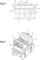
figure 1 is a perspective view of an electrical apparatus and a cover assembly mounted on the electrical apparatus; -
figure 2 is a side view of the electrical apparatus and the cover assembly; -
figure 3 is a perspective view of the electrical apparatus without cover assembly; -
figure 4 is a perspective view of the cover assembly; -
figure 5 is a front view of a removable shutter of the cover assembly; -
figure 6 is a another perspective view of the electrical apparatus and the cover assembly wherein; - In the following detailed description of the figures defined above, the same elements or the elements that are fulfilling identical functions may retain the same references so as to simplify the understanding of the invention.
- As illustrated in
figure 1 to 5 and 6 , acover assembly 1 for anelectrical apparatus 3 is configured for covering a plurality ofconductor terminals 5 of theelectrical apparatus 3. - As illustrated in
figures 1, 2 and5 , thecover assembly 1 has, for eachconductor terminal 5, a firstseparable part 7 and a secondseparable part 9 configured to be engender a firstsized terminal opening 11 when the firstseparable part 7 is removed and to engender a secondsized terminal opening 13 when the firstseparable part 7 and the secondseparable part 9 are removed. - In other words, the
cover assembly 1 has a plurality of firstseparable parts 7 and a plurality of secondseparable parts 9. Each firstseparable part 7 is arranged to be removed from thecover assembly 1 to create a first sized terminal opening 11 for the insertion of a correspondingly sized conductor. When the firstseparable part 7 and the associated secondseparable part 9 are removed, a bigger sized conductor can be inserted. - For each
conductor terminal 5, the firstseparable part 7 and the secondseparable part 9 are configured to prevent access to the correspondingterminal conductor 5 from the exterior at least according to an IP20 index. - The first
sized terminal opening 11 and the second sized terminal opening 13 respect at least an IP20 index. - The
cover assembly 1 comprises at least oneremovable shutter 15 on which are located the firstseparable parts 7 and the secondseparable parts 9. - The
removable shutter 15 comprises agrip 17. Saidgrip 17 corresponds to a protrusion designed to be seized by hand. Thegrip 17 presents a throughhole 19. - The
cover assembly 1 comprises abody 21 configured to be clipped on theelectrical apparatus 3, thebody 21 comprising at least oneinsertion slot 23 for receiving the at least oneremovable shutter 15. - The
body 21 remains on theelectrical apparatus 3 while removing a separable part. Thebody 21 is provided with at least one snap-inelement 25 to cooperate with a complementary snap-inelement 27 of the at least oneremovable shutter 15. The snap-inelement 25 corresponds to at least one hole and the complementary snap-inelement 27 corresponds to an at least one hook. - Here, the
cover assembly 1 comprises tworemovable shutters 15 located on opposed faces thecover assembly 1. - The
cover assembly 1 is adapted to cooperate with arear face 29 of theelectrical apparatus 3, theelectrical apparatus 3 being provided with twoparallel rows 31 of conductor terminals 4 configured for plugging conductors according to two opposed directions transversally to therows 31. - As illustrated in
figure 5 , eachremovable shutter 15 comprises a plurality ofstrips 33, eachstrip 33 comprising a corresponding firstseparable part 7 and secondseparable part 9. - For each
strip 33, the firstseparable part 7 and the secondseparable part 9 are adjacent fractions of thestrip 33, the firstseparable part 7 constituting an extremity of thestrip 33. - In other words, the removal of the first
separable part 7 reduces the length of thestrip 33 to engender the first sized terminal opening 11 in thecover assembly 1. The length of thestrip 33 can be further reduced by removing the secondseparable part 9. - For each
strip 33, the firstseparable part 7 and the secondseparable part 9 are pre-cut. Afirst groove 35 is located on thestrip 33 between the firstseparable part 7 and the secondseparable part 9. Asecond groove 37 is located on thestrip 33 to separate the secondseparable part 9 or both separable parts from thestrip 33. - The
cover assembly 1 further has at least oneeyelet 39 configured for receiving a seal. - The at least one
eyelet 39 is included in thebody 21. Saideyelet 39 is located in proximity to a corresponding throughhole 19 of aremovable shutter 15 so as to enable to seal together theremovable shutter 15 and thebody 21. - The
cover assembly 1 further has at least onereference orifice 41 configured to be facing a corresponding marking of theelectrical apparatus 3. - The at least one
reference orifice 41 is included in thebody 21. Thecover assembly 1 has a plurality ofreference orifices 41, eachreference orifice 41 corresponding toconductor terminal 5. - The plurality of
reference orifices 39 are aligned according two lines, each line being parallel and located next to acorresponding row 31 ofconductor terminal 5. - The at least one
reference orifice 39 and/or the at least oneinsertion slot 23 are located on arear part 43 of thecover assembly 1 extending transversally to the at least oneremovable shutter 15. - The
eyelet 39 is configured to enable an insertion of a cable of a seal transversally to the extension direction of therear part 43 ofcover assembly 1. - An
electrical testing assembly 45 comprising theelectrical apparatus 3 and acover assembly 1, wherein theelectrical apparatus 3 has afront face 47 presenting testing terminals and saidrear face 29 opposed to thefront face 47 and configured to receive thecover assembly 1. - The plurality of
conductor terminals 5 are located on therear face 29. The markings are located on therear face 29. The at least oneremovable shutter 15 are extending transversally to thefront face 47 and therear face 29. - The
electrical testing assembly 45 further comprises a first sizedelectrical conductor 49 plugged in aconductor terminal 5 of theelectrical apparatus 3 wherein the corresponding firstseparable part 7 is removed and the secondseparable part 9 is present, the space engendered between the firstsized terminal opening 11 and the first sizedelectrical conductor 49 being defined with respect to at least an IP20 index. - The electrical testing assembly further comprising a second sized
electrical conductor 51 plugged in aconductor terminal 5 or alternatively two first sized electrical conductors plugged in saidconductor terminal 5, wherein the corresponding firstseparable part 7 and the secondseparable part 9 are removed, the space engendered between the secondsized terminal opening 13 and the second sizedelectrical conductor 51 or alternatively two the first sizedelectrical conductors 49 being defined with respect to at least an IP20 index. - The
electrical apparatus 3 is here a terminal block dedicated for testing an electrical installation. The terminal block is for example dedicated for calibration, value measuring as current or voltage or other electrical values. - The
cover assembly 1 as described above enables to protect the plurality ofconductor terminals 5 of theelectrical apparatus 3. When only some of theconductor terminals 5 are used, thecover assembly 1 enables to create different sized terminal openings where necessary and sized according to the plugged conductors. - The
cover assembly 1 has then a safety purpose as it protects eachconductor terminal 5 of theelectrical apparatus 3 that are plugged or unplugged. In particular, it prevents a used to touch a conductive part. - The
removable shutters 15 enable to easily remove the necessary firstseparable parts 7 and secondseparable parts 9 from thecover assembly 1 as theremovable shutters 15 can be removed from thecover assembly 1 and thus from theelectrical apparatus 3. - As goes without saying, the invention is not limited to the sole embodiment described above by way of example, it encompasses all the variants.
Claims (15)
- Cover assembly (1) for an electrical apparatus (3) configured for covering a plurality of conductor terminals (5) of the electrical apparatus (3), the cover assembly (1) having for each conductor terminal (5) a first separable part (7) and a second separable part (9) configured to be engender a first sized terminal opening (11) when the first separable part (7) is removed and to engender a second sized terminal opening (13) when the first separable part (7) and the second separable part (9) are removed.
- Cover assembly (1) according to claim 1, wherein for each conductor terminal (5), the first separable part (7) and the second separable part (9) are configured to prevent access to the corresponding terminal conductor (5) from the exterior at least according to an IP20 index.
- Cover assembly (1) according to one of the claim 1 or 2, wherein the first sized terminal opening (11) and the second sized terminal opening (13) respect at least an IP20 index.
- Cover assembly (1) according to one of the claims 1 to 3, comprising at least one removable shutter (15) on which are located the first separable parts (7) and the second separable parts (9).
- Cover assembly (1) according to claim 4, comprising a body (21) configured to be clipped on the electrical apparatus (3), the body (21) comprising at least one insertion slot (23) for receiving the at least one removable shutter (15).
- Cover assembly (1) according to one of the claims 4 or 5, comprising two removable shutters (15) located on opposed faces the cover assembly (1).
- Cover assembly (1) according to one of the claims 4 to 6, wherein the or each removable shutter (15) comprises a plurality of strips (33), each strip (33) comprising a corresponding first separable part (7) and second separable part (9).
- Cover assembly (1) according to claim 7, wherein for each strip (33), the first separable part (7) and the second separable part (9) are adjacent fractions of the strip (33), the first separable part (7) constituting an extremity of the strip (33).
- Cover assembly (1) according to claim 8, wherein for each strip (33), the first separable part (7) and the second separable part (9) are pre-cut.
- Cover assembly (1) according to one of the claims 1 to 9, further having at least one eyelet (39) configured for receiving a seal.
- Cover assembly (1) according to one of the claims 1 to 10, further having at least one reference orifice (41) configured to be facing a corresponding marking of the electrical apparatus (3).
- Electrical testing assembly (45) comprising the electrical apparatus (3) and a cover assembly (1) according to one of the claims 1 to 11, wherein the electrical apparatus (3) has a front face (47) presenting testing terminals and a rear face (29) opposed to the front face (47) and configured to receive the cover assembly (1).
- Electrical testing assembly (45) according to claim 12, further comprising a first sized electrical conductor (49) plugged in a conductor terminal (5) of the electrical apparatus (3), wherein the corresponding first separable part (7) is removed and the second separable part (9) is present, the space engendered between the first sized terminal opening (11) and the first sized electrical conductor (49) being defined with respect to at least an IP20 index.
- Electrical testing assembly (45) according one of the claims 12 or 13, further comprising a second sized electrical conductor (51) plugged in a conductor terminal (5) or alternatively two first sized electrical conductors plugged in said conductor terminal (5), wherein the corresponding first separable part (7) and the second separable part (9) are removed, the space engendered between the second sized terminal opening (13) and the second sized electrical conductor (51) or alternatively two the first sized electrical conductors (41) being defined with respect to at least an IP20 index.
- Electrical testing assembly (45) according one of the claims 12 to 14, wherein the electrical apparatus (3) is a terminal block dedicated for testing an electrical installation.
Priority Applications (1)
| Application Number | Priority Date | Filing Date | Title |
|---|---|---|---|
| EP20305765.8A EP3937312B1 (en) | 2020-07-06 | 2020-07-06 | Cover assembly for an electrical apparatus |
Applications Claiming Priority (1)
| Application Number | Priority Date | Filing Date | Title |
|---|---|---|---|
| EP20305765.8A EP3937312B1 (en) | 2020-07-06 | 2020-07-06 | Cover assembly for an electrical apparatus |
Publications (2)
| Publication Number | Publication Date |
|---|---|
| EP3937312A1 true EP3937312A1 (en) | 2022-01-12 |
| EP3937312B1 EP3937312B1 (en) | 2025-08-20 |
Family
ID=71738078
Family Applications (1)
| Application Number | Title | Priority Date | Filing Date |
|---|---|---|---|
| EP20305765.8A Active EP3937312B1 (en) | 2020-07-06 | 2020-07-06 | Cover assembly for an electrical apparatus |
Country Status (1)
| Country | Link |
|---|---|
| EP (1) | EP3937312B1 (en) |
Citations (3)
| Publication number | Priority date | Publication date | Assignee | Title |
|---|---|---|---|---|
| FR2602948A1 (en) * | 1986-08-13 | 1988-02-19 | Merlin Gerin | Insulating module for multipole electrical equipment |
| EP1069578A1 (en) * | 1999-07-13 | 2001-01-17 | Power Controls Iberica S.A. | Terminal protection device for low voltage apparatus |
| US8698023B2 (en) * | 2010-07-29 | 2014-04-15 | Siemens Aktiengesellschaft | Electrical switch |
-
2020
- 2020-07-06 EP EP20305765.8A patent/EP3937312B1/en active Active
Patent Citations (3)
| Publication number | Priority date | Publication date | Assignee | Title |
|---|---|---|---|---|
| FR2602948A1 (en) * | 1986-08-13 | 1988-02-19 | Merlin Gerin | Insulating module for multipole electrical equipment |
| EP1069578A1 (en) * | 1999-07-13 | 2001-01-17 | Power Controls Iberica S.A. | Terminal protection device for low voltage apparatus |
| US8698023B2 (en) * | 2010-07-29 | 2014-04-15 | Siemens Aktiengesellschaft | Electrical switch |
Also Published As
| Publication number | Publication date |
|---|---|
| EP3937312B1 (en) | 2025-08-20 |
Similar Documents
| Publication | Publication Date | Title |
|---|---|---|
| US6932624B1 (en) | Modular signal and power connection device | |
| US7766689B2 (en) | Plug adapter for an electrical switching device | |
| JP6583323B2 (en) | Wiring connector and electrical equipment | |
| DK165719B (en) | CLAMP LEADER FOR CABLE LEADERS ISAS IN PHONE CABLES | |
| PL183079B1 (en) | Method of connecting a cramped insulating or connective termination and cramped insulating or connective termination as such | |
| CA2621098A1 (en) | Wire connectors for surge protectors and other electrical components | |
| HUP0800698A2 (en) | Cross connect terminal block | |
| EP2950398B1 (en) | System and method for identifying connections in an industrial enclosure | |
| EP3937312B1 (en) | Cover assembly for an electrical apparatus | |
| KR101850445B1 (en) | Waterproof connector | |
| KR101869545B1 (en) | Waterproof connector | |
| US11309654B2 (en) | Field device with electronic module including cover | |
| EP3477779B1 (en) | System comprising a ferrule terminal and a connection terminal block and electrical equipment comprising such system | |
| EP0849835A2 (en) | Electrical connectors and connecting parts therefor | |
| US20240243490A1 (en) | Plug connector having a bridging function | |
| KR101869540B1 (en) | Waterproof connector | |
| US4971572A (en) | Electrical connector | |
| US20140342597A1 (en) | Compliant multi-connector block device | |
| GB2323221A (en) | Electrical connectors and connecting parts therefor | |
| ITTO940251A1 (en) | POWER SUPPLY BASE | |
| WO2010032104A1 (en) | Wiring device | |
| KR101869542B1 (en) | Waterproof connector | |
| JP2017207411A (en) | Terminal for testing | |
| JP5224578B2 (en) | Outlet device | |
| US11543612B2 (en) | Connector plug, connector insertion method, and a connector removal method |
Legal Events
| Date | Code | Title | Description |
|---|---|---|---|
| PUAI | Public reference made under article 153(3) epc to a published international application that has entered the european phase |
Free format text: ORIGINAL CODE: 0009012 |
|
| STAA | Information on the status of an ep patent application or granted ep patent |
Free format text: STATUS: THE APPLICATION HAS BEEN PUBLISHED |
|
| AK | Designated contracting states |
Kind code of ref document: A1 Designated state(s): AL AT BE BG CH CY CZ DE DK EE ES FI FR GB GR HR HU IE IS IT LI LT LU LV MC MK MT NL NO PL PT RO RS SE SI SK SM TR |
|
| B565 | Issuance of search results under rule 164(2) epc |
Effective date: 20201201 |
|
| STAA | Information on the status of an ep patent application or granted ep patent |
Free format text: STATUS: REQUEST FOR EXAMINATION WAS MADE |
|
| 17P | Request for examination filed |
Effective date: 20220328 |
|
| RBV | Designated contracting states (corrected) |
Designated state(s): AL AT BE BG CH CY CZ DE DK EE ES FI FR GB GR HR HU IE IS IT LI LT LU LV MC MK MT NL NO PL PT RO RS SE SI SK SM TR |
|
| STAA | Information on the status of an ep patent application or granted ep patent |
Free format text: STATUS: EXAMINATION IS IN PROGRESS |
|
| 17Q | First examination report despatched |
Effective date: 20231023 |
|
| RAP1 | Party data changed (applicant data changed or rights of an application transferred) |
Owner name: TE CONNECTIVITY SOLUTIONS GMBH |
|
| GRAP | Despatch of communication of intention to grant a patent |
Free format text: ORIGINAL CODE: EPIDOSNIGR1 |
|
| STAA | Information on the status of an ep patent application or granted ep patent |
Free format text: STATUS: GRANT OF PATENT IS INTENDED |
|
| INTG | Intention to grant announced |
Effective date: 20250327 |
|
| GRAS | Grant fee paid |
Free format text: ORIGINAL CODE: EPIDOSNIGR3 |
|
| GRAA | (expected) grant |
Free format text: ORIGINAL CODE: 0009210 |
|
| STAA | Information on the status of an ep patent application or granted ep patent |
Free format text: STATUS: THE PATENT HAS BEEN GRANTED |
|
| AK | Designated contracting states |
Kind code of ref document: B1 Designated state(s): AL AT BE BG CH CY CZ DE DK EE ES FI FR GB GR HR HU IE IS IT LI LT LU LV MC MK MT NL NO PL PT RO RS SE SI SK SM TR |
|
| REG | Reference to a national code |
Ref country code: GB Ref legal event code: FG4D |
|
| REG | Reference to a national code |
Ref country code: CH Ref legal event code: EP |
|
| REG | Reference to a national code |
Ref country code: IE Ref legal event code: FG4D |
|
| REG | Reference to a national code |
Ref country code: DE Ref legal event code: R096 Ref document number: 602020056896 Country of ref document: DE |
|
| REG | Reference to a national code |
Ref country code: NL Ref legal event code: MP Effective date: 20250820 |
|
| PG25 | Lapsed in a contracting state [announced via postgrant information from national office to epo] |
Ref country code: IS Free format text: LAPSE BECAUSE OF FAILURE TO SUBMIT A TRANSLATION OF THE DESCRIPTION OR TO PAY THE FEE WITHIN THE PRESCRIBED TIME-LIMIT Effective date: 20251220 |
|
| PG25 | Lapsed in a contracting state [announced via postgrant information from national office to epo] |
Ref country code: NO Free format text: LAPSE BECAUSE OF FAILURE TO SUBMIT A TRANSLATION OF THE DESCRIPTION OR TO PAY THE FEE WITHIN THE PRESCRIBED TIME-LIMIT Effective date: 20251120 |
|
| REG | Reference to a national code |
Ref country code: LT Ref legal event code: MG9D |
|
| PG25 | Lapsed in a contracting state [announced via postgrant information from national office to epo] |
Ref country code: PT Free format text: LAPSE BECAUSE OF FAILURE TO SUBMIT A TRANSLATION OF THE DESCRIPTION OR TO PAY THE FEE WITHIN THE PRESCRIBED TIME-LIMIT Effective date: 20251222 |
|
| PG25 | Lapsed in a contracting state [announced via postgrant information from national office to epo] |
Ref country code: FI Free format text: LAPSE BECAUSE OF FAILURE TO SUBMIT A TRANSLATION OF THE DESCRIPTION OR TO PAY THE FEE WITHIN THE PRESCRIBED TIME-LIMIT Effective date: 20250820 |
|
| PG25 | Lapsed in a contracting state [announced via postgrant information from national office to epo] |
Ref country code: HR Free format text: LAPSE BECAUSE OF FAILURE TO SUBMIT A TRANSLATION OF THE DESCRIPTION OR TO PAY THE FEE WITHIN THE PRESCRIBED TIME-LIMIT Effective date: 20250820 Ref country code: NL Free format text: LAPSE BECAUSE OF FAILURE TO SUBMIT A TRANSLATION OF THE DESCRIPTION OR TO PAY THE FEE WITHIN THE PRESCRIBED TIME-LIMIT Effective date: 20250820 |
|
| PG25 | Lapsed in a contracting state [announced via postgrant information from national office to epo] |
Ref country code: GR Free format text: LAPSE BECAUSE OF FAILURE TO SUBMIT A TRANSLATION OF THE DESCRIPTION OR TO PAY THE FEE WITHIN THE PRESCRIBED TIME-LIMIT Effective date: 20251121 |
|
| PG25 | Lapsed in a contracting state [announced via postgrant information from national office to epo] |
Ref country code: SE Free format text: LAPSE BECAUSE OF FAILURE TO SUBMIT A TRANSLATION OF THE DESCRIPTION OR TO PAY THE FEE WITHIN THE PRESCRIBED TIME-LIMIT Effective date: 20250820 |
|
| PG25 | Lapsed in a contracting state [announced via postgrant information from national office to epo] |
Ref country code: LV Free format text: LAPSE BECAUSE OF FAILURE TO SUBMIT A TRANSLATION OF THE DESCRIPTION OR TO PAY THE FEE WITHIN THE PRESCRIBED TIME-LIMIT Effective date: 20250820 |
|
| PG25 | Lapsed in a contracting state [announced via postgrant information from national office to epo] |
Ref country code: BG Free format text: LAPSE BECAUSE OF FAILURE TO SUBMIT A TRANSLATION OF THE DESCRIPTION OR TO PAY THE FEE WITHIN THE PRESCRIBED TIME-LIMIT Effective date: 20250820 Ref country code: PL Free format text: LAPSE BECAUSE OF FAILURE TO SUBMIT A TRANSLATION OF THE DESCRIPTION OR TO PAY THE FEE WITHIN THE PRESCRIBED TIME-LIMIT Effective date: 20250820 |
|
| PG25 | Lapsed in a contracting state [announced via postgrant information from national office to epo] |
Ref country code: RS Free format text: LAPSE BECAUSE OF FAILURE TO SUBMIT A TRANSLATION OF THE DESCRIPTION OR TO PAY THE FEE WITHIN THE PRESCRIBED TIME-LIMIT Effective date: 20251120 |
|
| PG25 | Lapsed in a contracting state [announced via postgrant information from national office to epo] |
Ref country code: ES Free format text: LAPSE BECAUSE OF FAILURE TO SUBMIT A TRANSLATION OF THE DESCRIPTION OR TO PAY THE FEE WITHIN THE PRESCRIBED TIME-LIMIT Effective date: 20250820 |
|
| REG | Reference to a national code |
Ref country code: AT Ref legal event code: MK05 Ref document number: 1828386 Country of ref document: AT Kind code of ref document: T Effective date: 20250820 |
|
| PG25 | Lapsed in a contracting state [announced via postgrant information from national office to epo] |
Ref country code: SM Free format text: LAPSE BECAUSE OF FAILURE TO SUBMIT A TRANSLATION OF THE DESCRIPTION OR TO PAY THE FEE WITHIN THE PRESCRIBED TIME-LIMIT Effective date: 20250820 |
|
| PG25 | Lapsed in a contracting state [announced via postgrant information from national office to epo] |
Ref country code: DK Free format text: LAPSE BECAUSE OF FAILURE TO SUBMIT A TRANSLATION OF THE DESCRIPTION OR TO PAY THE FEE WITHIN THE PRESCRIBED TIME-LIMIT Effective date: 20250820 |
|
| PG25 | Lapsed in a contracting state [announced via postgrant information from national office to epo] |
Ref country code: AT Free format text: LAPSE BECAUSE OF FAILURE TO SUBMIT A TRANSLATION OF THE DESCRIPTION OR TO PAY THE FEE WITHIN THE PRESCRIBED TIME-LIMIT Effective date: 20250820 |
|
| PG25 | Lapsed in a contracting state [announced via postgrant information from national office to epo] |
Ref country code: IT Free format text: LAPSE BECAUSE OF FAILURE TO SUBMIT A TRANSLATION OF THE DESCRIPTION OR TO PAY THE FEE WITHIN THE PRESCRIBED TIME-LIMIT Effective date: 20250820 |
|
| PG25 | Lapsed in a contracting state [announced via postgrant information from national office to epo] |
Ref country code: CZ Free format text: LAPSE BECAUSE OF FAILURE TO SUBMIT A TRANSLATION OF THE DESCRIPTION OR TO PAY THE FEE WITHIN THE PRESCRIBED TIME-LIMIT Effective date: 20250820 |
|
| PG25 | Lapsed in a contracting state [announced via postgrant information from national office to epo] |
Ref country code: SK Free format text: LAPSE BECAUSE OF FAILURE TO SUBMIT A TRANSLATION OF THE DESCRIPTION OR TO PAY THE FEE WITHIN THE PRESCRIBED TIME-LIMIT Effective date: 20250820 Ref country code: EE Free format text: LAPSE BECAUSE OF FAILURE TO SUBMIT A TRANSLATION OF THE DESCRIPTION OR TO PAY THE FEE WITHIN THE PRESCRIBED TIME-LIMIT Effective date: 20250820 |