EP3937288A1 - Secondary battery and manufacturing method therefor - Google Patents
Secondary battery and manufacturing method therefor Download PDFInfo
- Publication number
- EP3937288A1 EP3937288A1 EP20787002.3A EP20787002A EP3937288A1 EP 3937288 A1 EP3937288 A1 EP 3937288A1 EP 20787002 A EP20787002 A EP 20787002A EP 3937288 A1 EP3937288 A1 EP 3937288A1
- Authority
- EP
- European Patent Office
- Prior art keywords
- electrode
- coating
- active material
- electrode active
- inactive
- Prior art date
- Legal status (The legal status is an assumption and is not a legal conclusion. Google has not performed a legal analysis and makes no representation as to the accuracy of the status listed.)
- Pending
Links
Images




Classifications
-
- H—ELECTRICITY
- H01—ELECTRIC ELEMENTS
- H01M—PROCESSES OR MEANS, e.g. BATTERIES, FOR THE DIRECT CONVERSION OF CHEMICAL ENERGY INTO ELECTRICAL ENERGY
- H01M10/00—Secondary cells; Manufacture thereof
- H01M10/42—Methods or arrangements for servicing or maintenance of secondary cells or secondary half-cells
- H01M10/4235—Safety or regulating additives or arrangements in electrodes, separators or electrolyte
-
- H—ELECTRICITY
- H01—ELECTRIC ELEMENTS
- H01M—PROCESSES OR MEANS, e.g. BATTERIES, FOR THE DIRECT CONVERSION OF CHEMICAL ENERGY INTO ELECTRICAL ENERGY
- H01M4/00—Electrodes
- H01M4/02—Electrodes composed of, or comprising, active material
- H01M4/13—Electrodes for accumulators with non-aqueous electrolyte, e.g. for lithium-accumulators; Processes of manufacture thereof
- H01M4/139—Processes of manufacture
-
- H—ELECTRICITY
- H01—ELECTRIC ELEMENTS
- H01M—PROCESSES OR MEANS, e.g. BATTERIES, FOR THE DIRECT CONVERSION OF CHEMICAL ENERGY INTO ELECTRICAL ENERGY
- H01M10/00—Secondary cells; Manufacture thereof
- H01M10/05—Accumulators with non-aqueous electrolyte
- H01M10/052—Li-accumulators
-
- H—ELECTRICITY
- H01—ELECTRIC ELEMENTS
- H01M—PROCESSES OR MEANS, e.g. BATTERIES, FOR THE DIRECT CONVERSION OF CHEMICAL ENERGY INTO ELECTRICAL ENERGY
- H01M10/00—Secondary cells; Manufacture thereof
- H01M10/05—Accumulators with non-aqueous electrolyte
- H01M10/058—Construction or manufacture
-
- H—ELECTRICITY
- H01—ELECTRIC ELEMENTS
- H01M—PROCESSES OR MEANS, e.g. BATTERIES, FOR THE DIRECT CONVERSION OF CHEMICAL ENERGY INTO ELECTRICAL ENERGY
- H01M10/00—Secondary cells; Manufacture thereof
- H01M10/05—Accumulators with non-aqueous electrolyte
- H01M10/058—Construction or manufacture
- H01M10/0585—Construction or manufacture of accumulators having only flat construction elements, i.e. flat positive electrodes, flat negative electrodes and flat separators
-
- H—ELECTRICITY
- H01—ELECTRIC ELEMENTS
- H01M—PROCESSES OR MEANS, e.g. BATTERIES, FOR THE DIRECT CONVERSION OF CHEMICAL ENERGY INTO ELECTRICAL ENERGY
- H01M10/00—Secondary cells; Manufacture thereof
- H01M10/05—Accumulators with non-aqueous electrolyte
- H01M10/058—Construction or manufacture
- H01M10/0587—Construction or manufacture of accumulators having only wound construction elements, i.e. wound positive electrodes, wound negative electrodes and wound separators
-
- H—ELECTRICITY
- H01—ELECTRIC ELEMENTS
- H01M—PROCESSES OR MEANS, e.g. BATTERIES, FOR THE DIRECT CONVERSION OF CHEMICAL ENERGY INTO ELECTRICAL ENERGY
- H01M4/00—Electrodes
- H01M4/02—Electrodes composed of, or comprising, active material
- H01M4/04—Processes of manufacture in general
- H01M4/0402—Methods of deposition of the material
- H01M4/0404—Methods of deposition of the material by coating on electrode collectors
-
- H—ELECTRICITY
- H01—ELECTRIC ELEMENTS
- H01M—PROCESSES OR MEANS, e.g. BATTERIES, FOR THE DIRECT CONVERSION OF CHEMICAL ENERGY INTO ELECTRICAL ENERGY
- H01M4/00—Electrodes
- H01M4/02—Electrodes composed of, or comprising, active material
- H01M4/13—Electrodes for accumulators with non-aqueous electrolyte, e.g. for lithium-accumulators; Processes of manufacture thereof
-
- H—ELECTRICITY
- H01—ELECTRIC ELEMENTS
- H01M—PROCESSES OR MEANS, e.g. BATTERIES, FOR THE DIRECT CONVERSION OF CHEMICAL ENERGY INTO ELECTRICAL ENERGY
- H01M4/00—Electrodes
- H01M4/02—Electrodes composed of, or comprising, active material
- H01M4/36—Selection of substances as active materials, active masses, active liquids
- H01M4/362—Composites
- H01M4/366—Composites as layered products
-
- H—ELECTRICITY
- H01—ELECTRIC ELEMENTS
- H01M—PROCESSES OR MEANS, e.g. BATTERIES, FOR THE DIRECT CONVERSION OF CHEMICAL ENERGY INTO ELECTRICAL ENERGY
- H01M50/00—Constructional details or processes of manufacture of the non-active parts of electrochemical cells other than fuel cells, e.g. hybrid cells
- H01M50/40—Separators; Membranes; Diaphragms; Spacing elements inside cells
- H01M50/471—Spacing elements inside cells other than separators, membranes or diaphragms; Manufacturing processes thereof
-
- H—ELECTRICITY
- H01—ELECTRIC ELEMENTS
- H01M—PROCESSES OR MEANS, e.g. BATTERIES, FOR THE DIRECT CONVERSION OF CHEMICAL ENERGY INTO ELECTRICAL ENERGY
- H01M50/00—Constructional details or processes of manufacture of the non-active parts of electrochemical cells other than fuel cells, e.g. hybrid cells
- H01M50/50—Current conducting connections for cells or batteries
- H01M50/572—Means for preventing undesired use or discharge
- H01M50/584—Means for preventing undesired use or discharge for preventing incorrect connections inside or outside the batteries
- H01M50/59—Means for preventing undesired use or discharge for preventing incorrect connections inside or outside the batteries characterised by the protection means
- H01M50/595—Tapes
-
- H—ELECTRICITY
- H01—ELECTRIC ELEMENTS
- H01M—PROCESSES OR MEANS, e.g. BATTERIES, FOR THE DIRECT CONVERSION OF CHEMICAL ENERGY INTO ELECTRICAL ENERGY
- H01M10/00—Secondary cells; Manufacture thereof
- H01M10/05—Accumulators with non-aqueous electrolyte
- H01M10/052—Li-accumulators
- H01M10/0525—Rocking-chair batteries, i.e. batteries with lithium insertion or intercalation in both electrodes; Lithium-ion batteries
-
- H—ELECTRICITY
- H01—ELECTRIC ELEMENTS
- H01M—PROCESSES OR MEANS, e.g. BATTERIES, FOR THE DIRECT CONVERSION OF CHEMICAL ENERGY INTO ELECTRICAL ENERGY
- H01M4/00—Electrodes
- H01M4/02—Electrodes composed of, or comprising, active material
- H01M2004/021—Physical characteristics, e.g. porosity, surface area
-
- Y—GENERAL TAGGING OF NEW TECHNOLOGICAL DEVELOPMENTS; GENERAL TAGGING OF CROSS-SECTIONAL TECHNOLOGIES SPANNING OVER SEVERAL SECTIONS OF THE IPC; TECHNICAL SUBJECTS COVERED BY FORMER USPC CROSS-REFERENCE ART COLLECTIONS [XRACs] AND DIGESTS
- Y02—TECHNOLOGIES OR APPLICATIONS FOR MITIGATION OR ADAPTATION AGAINST CLIMATE CHANGE
- Y02E—REDUCTION OF GREENHOUSE GAS [GHG] EMISSIONS, RELATED TO ENERGY GENERATION, TRANSMISSION OR DISTRIBUTION
- Y02E60/00—Enabling technologies; Technologies with a potential or indirect contribution to GHG emissions mitigation
- Y02E60/10—Energy storage using batteries
-
- Y—GENERAL TAGGING OF NEW TECHNOLOGICAL DEVELOPMENTS; GENERAL TAGGING OF CROSS-SECTIONAL TECHNOLOGIES SPANNING OVER SEVERAL SECTIONS OF THE IPC; TECHNICAL SUBJECTS COVERED BY FORMER USPC CROSS-REFERENCE ART COLLECTIONS [XRACs] AND DIGESTS
- Y02—TECHNOLOGIES OR APPLICATIONS FOR MITIGATION OR ADAPTATION AGAINST CLIMATE CHANGE
- Y02P—CLIMATE CHANGE MITIGATION TECHNOLOGIES IN THE PRODUCTION OR PROCESSING OF GOODS
- Y02P70/00—Climate change mitigation technologies in the production process for final industrial or consumer products
- Y02P70/50—Manufacturing or production processes characterised by the final manufactured product
Definitions
- the present invention relates to a secondary battery and a method for manufacturing the same, and more particularly, to a secondary battery in which, an occurrence of precipitation due to an uneven coating portion occurring when an electrode active material is applied is prevented, and a method for manufacturing the same.
- secondary batteries refer to chargeable and dischargeable batteries, unlike primary batteries that are not chargeable.
- the secondary batteries are being widely used in the high-tech electronic fields such as mobile phones, notebook computers, and camcorders.
- Such a secondary battery comprises an electrode assembly in which electrodes and separators are alternately stacked and a case accommodating the electrode assembly, and the electrode assembly has a structure in which the plurality of electrodes and the plurality of separators are alternately stacked.
- the plurality of electrodes comprise a first electrode and a second electrode.
- the first electrode comprises a first collector and a first electrode active material applied on the first collector
- the second electrode comprises a second collector and a second electrode active material applied on the second collector.
- the first electrode is a positive electrode
- the second electrode is a negative electrode
- a method for manufacturing the secondary battery having the above configuration comprises an electrode manufacturing step of manufacturing a first electrode and a second electrode and an electrode assembly manufacturing step of manufacturing an electrode assembly by stacking the first electrode and the second electrode with a separator therebetween.
- the electrode manufacturing step comprises a first electrode manufacturing process of applying a first active material from a coating start portion to a coating end portion of the first collector to manufacture the first electrode and a second electrode manufacturing process of applying a second active material from a coating start portion to a coating end portion of the second collector to manufacture the second electrode.
- the first electrode manufacturing process has a problem that the first active material is excessively applied on any one of the coating start portion and the coating end portion of the first collector while the first active material is applied from the coating start portion to the coating end portion of the first collector to cause an uneven coating portion, i.e., a hump.
- a hump an uneven coating portion
- the present invention is invented to solve the above problems, and thus the present invention provides a secondary battery, in which an inactive coating portion covering an uneven coating portion occurring on a first electrode that is a positive electrode is formed on a second electrode that is a negative electrode to stably cover the uneven coating portion occurring on the first electrode and thus prevent precipitation from occurring on the second electrode, thereby improving stability and battery performance, and a method for manufacturing the same.
- a secondary battery according to the present invention for achieving the above object comprises: a first electrode having a first collector and a first electrode active material on at least one surface of the first collector; and a second electrode having a second collector and a second electrode active material on at least one surface of the second collector, wherein an uneven coating portion at which the first electrode active material irregularly increases in amount and is located at at least one of a coating start portion or a coating end portion of the first electrode active material, and wherein an inactive coating portion configured to cover the uneven coating portion is located at at least one of a coating start portion or a coating end portion of the second electrode active material.
- the inactive coating portion is made of a same material as the second electrode active material.
- the inactive coating portion is coated with the second electrode active material in a state in which the at least one of the coating start portion or the coating end portion of the second electrode active material is extended so as to cover the uneven coating portion.
- the inactive coating portion has a thickness greater than from the coating start portion to the coating end portion of the second electrode active material.
- the inactive coating portion has a thickness corresponding to a thickness of the uneven coating portion.
- the first electrode is a positive electrode
- the second electrode is a negative electrode
- the first electrode further comprises an inactive tape attached to the uneven coating portion.
- the inactive tape is attached to surround the entire uneven coating portion.
- a method for manufacturing a secondary battery according to the present invention comprises: a first electrode manufacturing step (S10) of applying a first electrode active material on one surface of a first collector from a coating start portion to a coating end portion and applying the first electrode active material on a second surface of the first collector from the coating start portion to the coating end portion to manufacture a first electrode; and a second electrode manufacturing step (S20) of applying a second electrode active material on a first surface of a second collector from a coating start portion to a coating end portion and applying the second electrode active material on a second surface of the second collector from the coating start portion to the coating end portion to manufacture a second electrode, wherein, in the first electrode manufacturing step (S10), an uneven coating portion is formed at least one of the coating start portion or the coating end portion of the first electrode active material due to an increase of a loading amount of the first electrode active material, and wherein, in the second electrode manufacturing step (S20), an inactive coating portion covering the uneven coating portion is formed at at least one of the coating start portion or the coating end portion of
- a loading amount of the second electrode active material is increased and applied to form the inactive coating portion covering the uneven coating portion.
- the inactive coating portion has a thickness greater than a thickness of the second electrode active material from the coating start portion to the coating end portion of the second electrode active material.
- the inactive coating portion has a thickness corresponding to a thickness of the uneven coating portion.
- an electrode rolling step (S30) of rolling surfaces of the first electrode and the second electrode Further comprising, after the second electrode manufacturing step (S20), an electrode rolling step (S30) of rolling surfaces of the first electrode and the second electrode.
- a tape attachment step (S40) of attaching an inactive tape to the uneven coating portion formed at the first electrode is performed after the electrode rolling step (S30).
- the secondary battery according to the present invention may comprise the inactive coating portion covering the uneven coating portion occurring on the first electrode when the second electrode that is the negative electrode is manufactured. Therefore, the uneven coating portion may be continuously covered to prevent the precipitation from occurring on the second electrode, thereby improving the stability and performance of the secondary battery.
- a secondary battery 100 according to a first embodiment of the present invention comprises an electrode assembly 110, a can 120 accommodating the electrode assembly 110, and a cap assembly 130 mounted in an opening of the can 120.
- the electrode assembly 110 has a structure in which a plurality of electrodes and a plurality of separators are alternately stacked.
- the plurality of electrodes comprise a first electrode 111 and a second electrode 112. That is, the electrode assembly 110 comprises the first and second electrodes 111 and 112, which are stacked downward, and a separator 113 disposed between the first electrode 111 and the second electrode 112.
- the first electrode 111 comprises a first collector 111a and a first electrode active material 111b applied from a coating start portion A to a coating end portion B of the first collector 111a.
- the second electrode 112 comprises a second collector 112a and a second electrode active material 112b applied from a coating start portion C to a coating end portion D of the second collector 112a.
- the first electrode is a positive electrode
- the second electrode is a negative electrode
- the first electrode 111 that is the positive electrode is coated while the first electrode active material 111b is applied from the coating start portion A to the coating end portion B of the first collector 111a by using a coating device (not shown).
- a coating device since the coating device uniformly moves between the coating start portion A and the coating end portion B except for the coating start portion A and the coating end portion B, the first electrode active material may be uniformly applied.
- the first electrode active material is applied at a uniform thickness, since the coating on the coating start portion A and the coating end portion B starts or is finished in a state in which the coating device is stopped, the first electrode active material 111b is excessively applied to form an uneven coating portion 111c. That is, as illustrated in FIG. 2 , the uneven coating portion 111c is formed by the first electrode active material 111b that is excessively applied from the coating start portion A to the coating end portion B of the first collector 111a.
- the uneven coating portion 111c formed as described above is unintentionally coated when the first electrode is manufactured, when the first electrode 111 and the second electrode 112 are stacked, lithium may be precipitated on the second electrode 112 due to the uneven coating portion 111c to degrade stability and battery performance.
- the second electrode 112 comprises an inactive coating portion 112c covering the uneven coating portion 111c occurring on the first electrode 111.
- the uneven coating portion 111c may be stably covered through the inactive coating portion 112c to prevent the lithium from being precipitated on the electrode, thereby preventing the stability and the battery performance from being degraded.
- the inactive coating portion 112c is formed on any one of the coating start portion C and the coating end portion D of the second collector 112a included in the second electrode 112, which corresponds to the uneven coating portion 111c formed on the first electrode.
- the uneven coating portion 111c formed on the first electrode 111 may be covered by the inactive coating portion 112c formed on the second electrode 112.
- the inactive coating part 112c is made of the same material as the second electrode active material 112b. That is, the inactive coating portion 112c is made of the same material as the second electrode active material 112b applied on the second collector 112a.
- the inactive coating portion 112c and the uneven coating portion 111c are unintentionally coated, but the battery performance may be improved due to the increase of the active material.
- the inactive coating portion 112c is coated with the second electrode active material 112b from the coating start portion C to the coating end portion D of the second collector 112a.
- a loading amount of the second electrode active material 112b increases at the coating start portion C and the coating end portion D of the second collector 112a, and thus, the second electrode active material 112b applied on the coating start portion C and the coating end portion D is spread widely to form the inactive coating portion 112c.
- the inactive coating portion 112c may be provided by being coated with the second electrode active material 112b in a state in which at least one of the coating start portion C or the coating end portion D of the second electrode active material 112b extends so as to cover the uneven coating portion 111c. Accordingly, the second electrode active material 112b and the inactive coating portion 112c may be made of the same material to increase in easy of the manufacture.
- the inactive coating portion 112c may be coated at a thickness greater than that from the coating start portion C to the coating end portion D of the second electrode active material 112b. That is, since the uneven coating portion 111c occurs due to the increase of the loading amount of the first electrode active material 111b, the inactive coating portion 112c may be coated at a thickness greater than that from the coating start portion C to the coating end portion D of the second electrode active material 112b to stably cover the uneven coating portion 111c.
- the inactive coating portion 112c has a coating thickness corresponding to that of the uneven coating portion 111c. That is, when the inactive coating portion 112c has a coating thickness less than that of the uneven coating portion 111c, the uneven coating portion 111c may not be stably covered by the inactive coating portion 112c to cause the precipitation on the second electrode 112. Also, when the inactive coating portion 112c has a thickness greater than that of the uneven coating portion 111c, although the uneven coating portion 111c is stably covered, the second electrode active material 112b may be excessively used to significantly increase in manufacturing cost. Thus, the inactive coating portion 112c may have a thickness corresponding to that of the uneven coating portion 111c to reduce the manufacturing cost and stably cover the uneven coating portion 111c.
- a surface of the inactive coating portion 112c corresponding to the uneven coating portion 111c may be provided as a flat horizontal surface 112c-1.
- a connection between the second electrode active material 112b and the inactive coating portion 112c may be provided as an inclined surface so as not to form a stepped portion.
- the separator 113 may be prevented from being damaged by interfering with the connection portion between the second electrode active material 112b and the inactive coating portion 112c.
- the first electrode or the second electrode may be prevented from being folded or damaged by interfering with the uneven coating portion 111c at the connection portion between the second electrode active material 112b and the inactive coating portion 112c.
- the secondary battery 100 having the above-described configuration according to the first embodiment of the present invention comprises the inactive coating portion 112c on the second electrode 112 that is the negative electrode to stably cover the uneven coating portion 111c occurring on the first electrode 111 and prevent the lithium from being precipitated on the second electrode 112, thereby improving the stability and preventing the battery performance from being degraded.
- the secondary battery 100 may further comprise an inactive tape 114 attached to the uneven coating portion 111c formed on the first electrode 111. That is, when a meandering failure occurs in the first electrode and the second direction, which are stacked downward, the first electrode 111 and the second electrode are stacked at different angles, and thus, the inactive coating portion 112c of the second electrode 112 may not cover the uneven coating portion 111c formed on the first electrode 111. To prevent this phenomenon, the inactive tape 114 may be attached to the uneven coating portion 111c formed on the first electrode 111 to cover the uneven coating portion 111c. Thus, even though the first electrode 111 and the second electrode 112 are stacked at different angles, the uneven coating portion 111c may be stably covered.
- the inactive tape 114 may be attached to completely surround the uneven coating portion 111c to stably cover the entire uneven coating portion 111c.
- an adhesive 115 may be applied between the edge surface of the inactive tape 114 and the first electrode 111 to improve the adhesion of the edge surface of the inactive tape 114 through the adhesive 115.
- the inactive tape may be provided as a double-sided tape.
- the uneven coating portion 111c and the separator 113 which correspond to each other, may be attached to be connected to each other to prevent the meandering failure of the first electrode 111 having the uneven coating portion 111c from occurring.
- a method for manufacturing the secondary battery according to the first embodiment of the present invention comprises: a first electrode manufacturing step (S10) of manufacturing a first electrode 111; and a second electrode manufacturing step (S20) of manufacturing a second electrode 112.
- a first electrode active material 111b is applied on one surface (a top surface of a first collector when viewed in FIG. 5(a) ) of the first collector 111a from a coating start portion A to a coating end portion B.
- the first electrode active material 111b is applied on the other surface (a bottom surface of the first collector when viewed in FIG. 5(a) ) of the first collector 111a from the coating start portion A to the coating end portion B.
- the first electrode 111 may be manufactured through the above-described process.
- an uneven coating portion 111c is formed on at least one of the coating start portion A or the coating end portion B due to an increase of a loading amount of the first electrode active material 111b.
- a second electrode active material 112b is applied on one surface (a top surface of a second collector when viewed in FIG. 5(b) ) of the second collector 112a from a coating start portion C to a coating end portion D.
- the second electrode active material 112b is applied on the other surface (a bottom surface of the second collector when viewed in FIG. 5(b) ) of the second collector 112a from the coating start portion C to the coating end portion D.
- the second electrode 112 may be manufactured through the above-described process.
- an inactive coating portion 112c covering the uneven coating portion 111c is further formed on at least one of the coating start portion C or the coating end portion D of the second electrode active material 112b. That is, in the second electrode manufacturing step (S20), when at least one of the coating start portion C or the coating end portion D of the second electrode active material 112b is coated, the loading amount of the second electrode active material 112b increases to be applied on the inactive coating portion 112c covering the uneven coating portion 111c.
- the inactive coating portion 112c is applied thicker than a thickness of the second electrode active material 112b applied from the coating start portion C or the coating end portion D of the second electrode active material 112b to stably cover the uneven coating portion 111c. Furthermore, the inactive coating portion 112c may coated to a thickness corresponding to that of the uneven coating portion 111c to stably cover the uneven coating portion 111c.
- an electrode rolling step (S30) of rolling a surface of each of the first electrode 111 and the second electrode 112 is further performed.
- the first electrode 111 and the second electrode 112 are rolled using a rolling roll 20 to uniformly adjust a coating thickness of each of the first electrode active material 111b of the first electrode 111 and the second electrode active material 112b of the second electrode 112.
- the excessively protruding uneven coating portion 111c and the inactive coating portion 112c covering the uneven coating portion 111c are rolled together with each other to reduce a thickness of each of the uneven coating portion 111c and the inactive coating portion 112c.
- a tape attachment step (S40) of attaching an inactive tape to the uneven coating portion formed on the first electrode is further performed.
- the tape attachment step S40 attaches the inactive tape 114 to surround the entire uneven coating part 111c formed on the first electrode 111. Then, even though a stacking error of the first and second electrodes 111 and 112 occurs, the uneven coating part 111c may be stably covered through the inactive tape 114.
- An adhesive 115 is further applied to a boundary between the inactive tape 114 and the uneven coating portion 111c to increase in adhesion of an edge surface of the inactive tape 114.
- a secondary battery manufacturing step (S60) for completing the secondary battery 100 is further performed.
- a separator 113 is disposed between the first electrode 111 and the second electrode 112 to manufacture an electrode assembly 110.
- the electrode assembly 110 is accommodated in a can 120, and a cap assembly 130 is mounted in an opening of the can 120 to manufacture the secondary battery 100.
- the uneven coating portion 111c formed on the first electrode 111 and the inactive coating portion 112c of the second electrode 112 are disposed to correspond to each other, the occurrence of the precipitation on the second electrode 112 may be prevented to improve stability and prevent battery performance from being degraded.
- Three second electrodes which are negative electrodes manufactured by the method for manufacturing the secondary battery of the present invention, are prepared, and thickness and loading amounts of the prepared second electrodes are measured. Particularly, a thickness at a portion of a second electrode active material applied on each of the second electrodes and a thickness at a portion of an inactive coating portion are measured.
- the electrode thickness may be measured as high as about 30 ⁇ m, and the loading amount may be measured as high as about 20 mg/ 25 cm 2 .
- a nitrogen/phosphorus ratio may increase from 104% to 110%, and a supply rate may increase from 23.6% to 42.6% in the second electrode, which is the negative electrode, compared to the first electrode, which is the positive electrode. This may prevent lithium from being precipitated on the second electrode even if the uneven coating portion is formed on the first electrode that is the positive electrode.
- the thickness and loading amount of the inactive coating portion 112c that is a single-sided coating portion are greater than the thickness and loading amount of the second electrode active material 112b that is a double-sided coating portion. Therefore, the inactive coating portion 112c for covering the uneven coating portion 111c formed on the first electrode 111 may be stably formed.
- FIG. 7(a) illustrates thicknesses of the three second electrodes 112 manufactured by the method for manufacturing the secondary battery before rolling according to the present invention
- FIG. 7(b) illustrates thicknesses of the three second electrodes 112 manufactured by the method for manufacturing the secondary battery after rolling according to the present invention.
- the thickness of each of the second electrode active material applied on the second electrode 112 and the inactive coating portion is reduced, and in particular, it is seen that a portion between the second electrode active material and the inactive coating portion is changed into a gentle inclined surface. Therefore, the separator may be prevented from being damaged by interfering between the second electrode active material and the inactive coating portion.
Landscapes
- Chemical & Material Sciences (AREA)
- Chemical Kinetics & Catalysis (AREA)
- Electrochemistry (AREA)
- General Chemical & Material Sciences (AREA)
- Engineering & Computer Science (AREA)
- Manufacturing & Machinery (AREA)
- Materials Engineering (AREA)
- Composite Materials (AREA)
- Battery Electrode And Active Subsutance (AREA)
- Secondary Cells (AREA)
Abstract
Description
- The present application claims the benefit of the priority of
Korean Patent Application No. 10-2019-0040973, filed on April 08, 2019 - The present invention relates to a secondary battery and a method for manufacturing the same, and more particularly, to a secondary battery in which, an occurrence of precipitation due to an uneven coating portion occurring when an electrode active material is applied is prevented, and a method for manufacturing the same.
- In general, secondary batteries refer to chargeable and dischargeable batteries, unlike primary batteries that are not chargeable. The secondary batteries are being widely used in the high-tech electronic fields such as mobile phones, notebook computers, and camcorders.
- Such a secondary battery comprises an electrode assembly in which electrodes and separators are alternately stacked and a case accommodating the electrode assembly, and the electrode assembly has a structure in which the plurality of electrodes and the plurality of separators are alternately stacked.
- Here, the plurality of electrodes comprise a first electrode and a second electrode. The first electrode comprises a first collector and a first electrode active material applied on the first collector, and the second electrode comprises a second collector and a second electrode active material applied on the second collector.
- The first electrode is a positive electrode, and the second electrode is a negative electrode.
- A method for manufacturing the secondary battery having the above configuration comprises an electrode manufacturing step of manufacturing a first electrode and a second electrode and an electrode assembly manufacturing step of manufacturing an electrode assembly by stacking the first electrode and the second electrode with a separator therebetween. The electrode manufacturing step comprises a first electrode manufacturing process of applying a first active material from a coating start portion to a coating end portion of the first collector to manufacture the first electrode and a second electrode manufacturing process of applying a second active material from a coating start portion to a coating end portion of the second collector to manufacture the second electrode.
- Here, the first electrode manufacturing process has a problem that the first active material is excessively applied on any one of the coating start portion and the coating end portion of the first collector while the first active material is applied from the coating start portion to the coating end portion of the first collector to cause an uneven coating portion, i.e., a hump. As a result, there is a problem that precipitation occurs on the second electrode that is the negative electrode due to the hump to degrade stability and battery performance.
- The present invention is invented to solve the above problems, and thus the present invention provides a secondary battery, in which an inactive coating portion covering an uneven coating portion occurring on a first electrode that is a positive electrode is formed on a second electrode that is a negative electrode to stably cover the uneven coating portion occurring on the first electrode and thus prevent precipitation from occurring on the second electrode, thereby improving stability and battery performance, and a method for manufacturing the same.
- A secondary battery according to the present invention for achieving the above object comprises: a first electrode having a first collector and a first electrode active material on at least one surface of the first collector; and a second electrode having a second collector and a second electrode active material on at least one surface of the second collector, wherein an uneven coating portion at which the first electrode active material irregularly increases in amount and is located at at least one of a coating start portion or a coating end portion of the first electrode active material, and wherein an inactive coating portion configured to cover the uneven coating portion is located at at least one of a coating start portion or a coating end portion of the second electrode active material.
- Wherein the inactive coating portion is made of a same material as the second electrode active material.
- Wherein the inactive coating portion is coated with the second electrode active material in a state in which the at least one of the coating start portion or the coating end portion of the second electrode active material is extended so as to cover the uneven coating portion.
- Wherein the inactive coating portion has a thickness greater than from the coating start portion to the coating end portion of the second electrode active material.
- Wherein the inactive coating portion has a thickness corresponding to a thickness of the uneven coating portion.
- Wherein the first electrode is a positive electrode, and the second electrode is a negative electrode.
- Wherein the first electrode further comprises an inactive tape attached to the uneven coating portion.
- Wherein the inactive tape is attached to surround the entire uneven coating portion.
- A method for manufacturing a secondary battery according to the present invention comprises: a first electrode manufacturing step (S10) of applying a first electrode active material on one surface of a first collector from a coating start portion to a coating end portion and applying the first electrode active material on a second surface of the first collector from the coating start portion to the coating end portion to manufacture a first electrode; and a second electrode manufacturing step (S20) of applying a second electrode active material on a first surface of a second collector from a coating start portion to a coating end portion and applying the second electrode active material on a second surface of the second collector from the coating start portion to the coating end portion to manufacture a second electrode, wherein, in the first electrode manufacturing step (S10), an uneven coating portion is formed at least one of the coating start portion or the coating end portion of the first electrode active material due to an increase of a loading amount of the first electrode active material, and wherein, in the second electrode manufacturing step (S20), an inactive coating portion covering the uneven coating portion is formed at at least one of the coating start portion or the coating end portion of the second electrode active material.
- Wherein, in the second electrode manufacturing step (S20), after the at least one of the coating start portion or the coating end portion of the second electrode active material is coated, a loading amount of the second electrode active material is increased and applied to form the inactive coating portion covering the uneven coating portion.
- Wherein the inactive coating portion has a thickness greater than a thickness of the second electrode active material from the coating start portion to the coating end portion of the second electrode active material.
- Wherein the inactive coating portion has a thickness corresponding to a thickness of the uneven coating portion.
- Further comprising, after the second electrode manufacturing step (S20), an electrode rolling step (S30) of rolling surfaces of the first electrode and the second electrode.
- Further comprising, after the electrode rolling step (S30), a tape attachment step (S40) of attaching an inactive tape to the uneven coating portion formed at the first electrode.
- Further comprising, after the tape attachment step (S40), a secondary battery manufacturing step (S60) of interposing a separator between the first electrode and the second electrode to manufacture the secondary battery.
- The secondary battery according to the present invention may comprise the inactive coating portion covering the uneven coating portion occurring on the first electrode when the second electrode that is the negative electrode is manufactured. Therefore, the uneven coating portion may be continuously covered to prevent the precipitation from occurring on the second electrode, thereby improving the stability and performance of the secondary battery.
-
-
FIG. 1 is a perspective view of a secondary battery according to a first embodiment of the present invention. -
FIG. 2 is a cross-sectional view of an electrode assembly of the secondary battery according to the first embodiment of the present invention. -
FIG. 3 is a cross-sectional view illustrating an inactive tape of the secondary battery according to the first embodiment of the present invention. -
FIG. 4 is a flowchart illustrating a method for manufacturing the second battery according to the first embodiment of the present invention. -
FIG. 5 is a process chart illustrating a method for manufacturing the second battery according to the first embodiment of the present invention. -
FIG. 6 is a table illustrating values obtained by measuring thicknesses of a second electrode active material and an inactive coating portion of a second electrode manufactured by the method for manufacturing the secondary battery according to the first embodiment of the present invention. -
FIG. 7 is a graph illustrating a thickness of the second electrode before and after rolling, which is manufactured by the method for manufacturing the secondary battery according to the first embodiment of the present invention. - Hereinafter, embodiments of the present invention will be described in detail with reference to the accompanying drawings in such a manner that the technical idea of the present invention may easily be carried out by a person with ordinary skill in the art to which the invention pertains. The present invention may, however, be embodied in different forms and should not be construed as limited to the embodiments set forth herein. In the drawings, anything unnecessary for describing the present invention will be omitted for clarity, and also like reference numerals in the drawings denote like elements.
- As illustrated in
FIG. 1 , asecondary battery 100 according to a first embodiment of the present invention comprises anelectrode assembly 110, a can 120 accommodating theelectrode assembly 110, and acap assembly 130 mounted in an opening of thecan 120. - As illustrated in
FIG. 2 , theelectrode assembly 110 has a structure in which a plurality of electrodes and a plurality of separators are alternately stacked. The plurality of electrodes comprise afirst electrode 111 and asecond electrode 112. That is, theelectrode assembly 110 comprises the first andsecond electrodes separator 113 disposed between thefirst electrode 111 and thesecond electrode 112. - The
first electrode 111 comprises afirst collector 111a and a first electrodeactive material 111b applied from a coating start portion A to a coating end portion B of thefirst collector 111a. - The
second electrode 112 comprises asecond collector 112a and a second electrodeactive material 112b applied from a coating start portion C to a coating end portion D of thesecond collector 112a. - Here, the first electrode is a positive electrode, and the second electrode is a negative electrode.
- The
first electrode 111 that is the positive electrode is coated while the first electrodeactive material 111b is applied from the coating start portion A to the coating end portion B of thefirst collector 111a by using a coating device (not shown). Here, since the coating device uniformly moves between the coating start portion A and the coating end portion B except for the coating start portion A and the coating end portion B, the first electrode active material may be uniformly applied. However, although the first electrode active material is applied at a uniform thickness, since the coating on the coating start portion A and the coating end portion B starts or is finished in a state in which the coating device is stopped, the first electrodeactive material 111b is excessively applied to form anuneven coating portion 111c. That is, as illustrated inFIG. 2 , theuneven coating portion 111c is formed by the first electrodeactive material 111b that is excessively applied from the coating start portion A to the coating end portion B of thefirst collector 111a. - Since the
uneven coating portion 111c formed as described above is unintentionally coated when the first electrode is manufactured, when thefirst electrode 111 and thesecond electrode 112 are stacked, lithium may be precipitated on thesecond electrode 112 due to theuneven coating portion 111c to degrade stability and battery performance. - In order to solve the above problems, the
second electrode 112 comprises aninactive coating portion 112c covering theuneven coating portion 111c occurring on thefirst electrode 111. Thus, theuneven coating portion 111c may be stably covered through theinactive coating portion 112c to prevent the lithium from being precipitated on the electrode, thereby preventing the stability and the battery performance from being degraded. - That is, the
inactive coating portion 112c is formed on any one of the coating start portion C and the coating end portion D of thesecond collector 112a included in thesecond electrode 112, which corresponds to theuneven coating portion 111c formed on the first electrode. Thus, theuneven coating portion 111c formed on thefirst electrode 111 may be covered by theinactive coating portion 112c formed on thesecond electrode 112. - The
inactive coating part 112c is made of the same material as the second electrodeactive material 112b. That is, theinactive coating portion 112c is made of the same material as the second electrodeactive material 112b applied on thesecond collector 112a. Thus, it is possible to increase in easy of the manufacture, and in particular, theinactive coating portion 112c and theuneven coating portion 111c are unintentionally coated, but the battery performance may be improved due to the increase of the active material. - That is to say, the
inactive coating portion 112c is coated with the second electrodeactive material 112b from the coating start portion C to the coating end portion D of thesecond collector 112a. Here, a loading amount of the second electrodeactive material 112b increases at the coating start portion C and the coating end portion D of thesecond collector 112a, and thus, the second electrodeactive material 112b applied on the coating start portion C and the coating end portion D is spread widely to form theinactive coating portion 112c. - In summary, the
inactive coating portion 112c may be provided by being coated with the second electrodeactive material 112b in a state in which at least one of the coating start portion C or the coating end portion D of the second electrodeactive material 112b extends so as to cover theuneven coating portion 111c. Accordingly, the second electrodeactive material 112b and theinactive coating portion 112c may be made of the same material to increase in easy of the manufacture. - The
inactive coating portion 112c may be coated at a thickness greater than that from the coating start portion C to the coating end portion D of the second electrodeactive material 112b. That is, since theuneven coating portion 111c occurs due to the increase of the loading amount of the first electrodeactive material 111b, theinactive coating portion 112c may be coated at a thickness greater than that from the coating start portion C to the coating end portion D of the second electrodeactive material 112b to stably cover theuneven coating portion 111c. - Particularly, the
inactive coating portion 112c has a coating thickness corresponding to that of theuneven coating portion 111c. That is, when theinactive coating portion 112c has a coating thickness less than that of theuneven coating portion 111c, theuneven coating portion 111c may not be stably covered by theinactive coating portion 112c to cause the precipitation on thesecond electrode 112. Also, when theinactive coating portion 112c has a thickness greater than that of theuneven coating portion 111c, although theuneven coating portion 111c is stably covered, the second electrodeactive material 112b may be excessively used to significantly increase in manufacturing cost. Thus, theinactive coating portion 112c may have a thickness corresponding to that of theuneven coating portion 111c to reduce the manufacturing cost and stably cover theuneven coating portion 111c. - A surface of the
inactive coating portion 112c corresponding to theuneven coating portion 111c may be provided as a flathorizontal surface 112c-1. Thus, even though the surface of theuneven coating portion 111c is uneven, friction between theuneven coating portion 111c and theinactive coating portion 112c may be minimized, and theuneven coating portion 111c may be stably covered. - A connection between the second electrode
active material 112b and theinactive coating portion 112c may be provided as an inclined surface so as not to form a stepped portion. Thus, theseparator 113 may be prevented from being damaged by interfering with the connection portion between the second electrodeactive material 112b and theinactive coating portion 112c. Particularly, the first electrode or the second electrode may be prevented from being folded or damaged by interfering with theuneven coating portion 111c at the connection portion between the second electrodeactive material 112b and theinactive coating portion 112c. - The
secondary battery 100 having the above-described configuration according to the first embodiment of the present invention comprises theinactive coating portion 112c on thesecond electrode 112 that is the negative electrode to stably cover theuneven coating portion 111c occurring on thefirst electrode 111 and prevent the lithium from being precipitated on thesecond electrode 112, thereby improving the stability and preventing the battery performance from being degraded. - As illustrated in
FIG. 3 , thesecondary battery 100 according to the first embodiment of the present invention may further comprise aninactive tape 114 attached to theuneven coating portion 111c formed on thefirst electrode 111. That is, when a meandering failure occurs in the first electrode and the second direction, which are stacked downward, thefirst electrode 111 and the second electrode are stacked at different angles, and thus, theinactive coating portion 112c of thesecond electrode 112 may not cover theuneven coating portion 111c formed on thefirst electrode 111. To prevent this phenomenon, theinactive tape 114 may be attached to theuneven coating portion 111c formed on thefirst electrode 111 to cover theuneven coating portion 111c. Thus, even though thefirst electrode 111 and thesecond electrode 112 are stacked at different angles, theuneven coating portion 111c may be stably covered. - The
inactive tape 114 may be attached to completely surround theuneven coating portion 111c to stably cover the entireuneven coating portion 111c. - In the
secondary battery 100 according to the first embodiment of the present invention, in order to increase in adhesion of an edge surface of the inactive tape, an adhesive 115 may be applied between the edge surface of theinactive tape 114 and thefirst electrode 111 to improve the adhesion of the edge surface of theinactive tape 114 through the adhesive 115. - Particularly, the inactive tape may be provided as a double-sided tape. As a result, the
uneven coating portion 111c and theseparator 113, which correspond to each other, may be attached to be connected to each other to prevent the meandering failure of thefirst electrode 111 having theuneven coating portion 111c from occurring. - Hereinafter, a method for manufacturing the secondary battery according to the first embodiment of the present invention will be described.
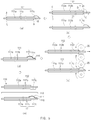
- As illustrated in
FIGS. 4 and5 , a method for manufacturing the secondary battery according to the first embodiment of the present invention comprises: a first electrode manufacturing step (S10) of manufacturing afirst electrode 111; and a second electrode manufacturing step (S20) of manufacturing asecond electrode 112. - Referring to
FIG. 5(a) , in the first electrode manufacturing step (S10), a first electrodeactive material 111b is applied on one surface (a top surface of a first collector when viewed inFIG. 5(a) ) of thefirst collector 111a from a coating start portion A to a coating end portion B. Next, the first electrodeactive material 111b is applied on the other surface (a bottom surface of the first collector when viewed inFIG. 5(a) ) of thefirst collector 111a from the coating start portion A to the coating end portion B. Thefirst electrode 111 may be manufactured through the above-described process. - Here, in the first electrode manufacturing step (S10), an
uneven coating portion 111c is formed on at least one of the coating start portion A or the coating end portion B due to an increase of a loading amount of the first electrodeactive material 111b. - Referring to
FIG. 5(b) , in the second electrode manufacturing step (S20), a second electrodeactive material 112b is applied on one surface (a top surface of a second collector when viewed inFIG. 5(b) ) of thesecond collector 112a from a coating start portion C to a coating end portion D. Next, the second electrodeactive material 112b is applied on the other surface (a bottom surface of the second collector when viewed inFIG. 5(b) ) of thesecond collector 112a from the coating start portion C to the coating end portion D. Thesecond electrode 112 may be manufactured through the above-described process. - Here, in the second electrode manufacturing step (S20), an
inactive coating portion 112c covering theuneven coating portion 111c is further formed on at least one of the coating start portion C or the coating end portion D of the second electrodeactive material 112b. That is, in the second electrode manufacturing step (S20), when at least one of the coating start portion C or the coating end portion D of the second electrodeactive material 112b is coated, the loading amount of the second electrodeactive material 112b increases to be applied on theinactive coating portion 112c covering theuneven coating portion 111c. - Particularly, in the second electrode manufacturing step (S20), the
inactive coating portion 112c is applied thicker than a thickness of the second electrodeactive material 112b applied from the coating start portion C or the coating end portion D of the second electrodeactive material 112b to stably cover theuneven coating portion 111c. Furthermore, theinactive coating portion 112c may coated to a thickness corresponding to that of theuneven coating portion 111c to stably cover theuneven coating portion 111c. - After the second electrode manufacturing step (S20), an electrode rolling step (S30) of rolling a surface of each of the
first electrode 111 and thesecond electrode 112 is further performed. - Referring to
FIG. 5(c) , in the electrode rolling step (S30), thefirst electrode 111 and thesecond electrode 112 are rolled using a rollingroll 20 to uniformly adjust a coating thickness of each of the first electrodeactive material 111b of thefirst electrode 111 and the second electrodeactive material 112b of thesecond electrode 112. - Particularly, in the electrode rolling step (S30), the excessively protruding
uneven coating portion 111c and theinactive coating portion 112c covering theuneven coating portion 111c are rolled together with each other to reduce a thickness of each of theuneven coating portion 111c and theinactive coating portion 112c. - After the electrode rolling step (S30), a tape attachment step (S40) of attaching an inactive tape to the uneven coating portion formed on the first electrode is further performed.
- Referring to
FIG. 5(d) , the tape attachment step S40 attaches theinactive tape 114 to surround the entireuneven coating part 111c formed on thefirst electrode 111. Then, even though a stacking error of the first andsecond electrodes uneven coating part 111c may be stably covered through theinactive tape 114. - An adhesive 115 is further applied to a boundary between the
inactive tape 114 and theuneven coating portion 111c to increase in adhesion of an edge surface of theinactive tape 114. - After the tape attachment step (S40), a secondary battery manufacturing step (S60) for completing the
secondary battery 100 is further performed. - Referring to
FIG. 5(e) , in the secondary battery manufacturing step (S60), aseparator 113 is disposed between thefirst electrode 111 and thesecond electrode 112 to manufacture anelectrode assembly 110. - Also, as illustrated in
FIG. 1 , theelectrode assembly 110 is accommodated in acan 120, and acap assembly 130 is mounted in an opening of thecan 120 to manufacture thesecondary battery 100. - Here, as the
uneven coating portion 111c formed on thefirst electrode 111 and theinactive coating portion 112c of thesecond electrode 112 are disposed to correspond to each other, the occurrence of the precipitation on thesecond electrode 112 may be prevented to improve stability and prevent battery performance from being degraded. - Three second electrodes, which are negative electrodes manufactured by the method for manufacturing the secondary battery of the present invention, are prepared, and thickness and loading amounts of the prepared second electrodes are measured. Particularly, a thickness at a portion of a second electrode active material applied on each of the second electrodes and a thickness at a portion of an inactive coating portion are measured.
- Here, the electrode thickness may be measured as high as about 30 µm, and the loading amount may be measured as high as about 20 mg/ 25 cm2. Also, a nitrogen/phosphorus ratio may increase from 104% to 110%, and a supply rate may increase from 23.6% to 42.6% in the second electrode, which is the negative electrode, compared to the first electrode, which is the positive electrode. This may prevent lithium from being precipitated on the second electrode even if the uneven coating portion is formed on the first electrode that is the positive electrode.
- As a result of measuring as described above, an experiment table as shown in
FIG. 6 may be obtained. - That is, when comparing the thicknesses and loading amounts of the three
second electrodes 112 manufactured by the method for manufacturing the secondary battery according to the present invention, it is seen that the thickness and loading amount of theinactive coating portion 112c that is a single-sided coating portion are greater than the thickness and loading amount of the second electrodeactive material 112b that is a double-sided coating portion. Therefore, theinactive coating portion 112c for covering theuneven coating portion 111c formed on thefirst electrode 111 may be stably formed. - Also,
FIG. 7(a) illustrates thicknesses of the threesecond electrodes 112 manufactured by the method for manufacturing the secondary battery before rolling according to the present invention, andFIG. 7(b) illustrates thicknesses of the threesecond electrodes 112 manufactured by the method for manufacturing the secondary battery after rolling according to the present invention. - Referring to the graph of
FIG. 7 , it is seen that the thickness of each of the second electrode active material applied on thesecond electrode 112 and the inactive coating portion is reduced, and in particular, it is seen that a portion between the second electrode active material and the inactive coating portion is changed into a gentle inclined surface. Therefore, the separator may be prevented from being damaged by interfering between the second electrode active material and the inactive coating portion. - Accordingly, the scope of the present invention is defined by the appended claims more than the foregoing description and the exemplary embodiments described therein. Various modifications made within the meaning of an equivalent of the claims of the invention and within the claims are to be regarded to be in the scope of the present invention.
Claims (15)
- A secondary battery comprising:a first electrode having a first collector and a first electrode active material on at least one surface of the first collector; anda second electrode having a second collector and a second electrode active material on at least one surface of the second collector,wherein an uneven coating portion at which the first electrode active material irregularly increases in amount and is located at at least one of a coating start portion or a coating end portion of the first electrode active material, andwherein an inactive coating portion configured to cover the uneven coating portion is located at at least one of a coating start portion or a coating end portion of the second electrode active material.
- The secondary battery of claim 1, wherein the inactive coating portion is made of a same material as the second electrode active material.
- The secondary battery of claim 1, wherein the inactive coating portion is coated with the second electrode active material in a state in which the at least one of the coating start portion or the coating end portion of the second electrode active material is extended so as to cover the uneven coating portion.
- The secondary battery of claim 1, wherein the inactive coating portion has a thickness greater than from the coating start portion to the coating end portion of the second electrode active material.
- The secondary battery of claim 1, wherein the inactive coating portion has a thickness corresponding to a thickness of the uneven coating portion.
- The secondary battery of claim 1, wherein the first electrode is a positive electrode, and the second electrode is a negative electrode.
- The secondary battery of claim 1, wherein the first electrode further comprises an inactive tape attached to the uneven coating portion.
- The secondary battery of claim 7, wherein the inactive tape is attached to surround the entire uneven coating portion.
- A method for manufacturing a secondary battery, the method comprising:a first electrode manufacturing step (S10) of applying a first electrode active material on one surface of a first collector from a coating start portion to a coating end portion and applying the first electrode active material on a second surface of the first collector from the coating start portion to the coating end portion to manufacture a first electrode; anda second electrode manufacturing step (S20) of applying a second electrode active material on a first surface of a second collector from a coating start portion to a coating end portion and applying the second electrode active material on a second surface of the second collector from the coating start portion to the coating end portion to manufacture a second electrode,wherein, in the first electrode manufacturing step (S10), an uneven coating portion is formed at least one of the coating start portion or the coating end portion of the first electrode active material due to an increase of a loading amount of the first electrode active material, andwherein, in the second electrode manufacturing step (S20), an inactive coating portion covering the uneven coating portion is formed at at least one of the coating start portion or the coating end portion of the second electrode active material.
- The method of claim 9, wherein, in the second electrode manufacturing step (S20), after the at least one of the coating start portion or the coating end portion of the second electrode active material is coated, a loading amount of the second electrode active material is increased and applied to form the inactive coating portion covering the uneven coating portion.
- The method of claim 10, wherein the inactive coating portion has a thickness greater than a thickness of the second electrode active material from the coating start portion to the coating end portion of the second electrode active material.
- The method of claim 10, wherein the inactive coating portion has a thickness corresponding to a thickness of the uneven coating portion.
- The method of claim 9, further comprising, after the second electrode manufacturing step (S20), an electrode rolling step (S30) of rolling surfaces of the first electrode and the second electrode.
- The method of claim 13, further comprising, after the electrode rolling step (S30), a tape attachment step (S40) of attaching an inactive tape to the uneven coating portion formed at the first electrode.
- The method of claim 14, further comprising, after the tape attachment step (S40), a secondary battery manufacturing step (S60) of interposing a separator between the first electrode and the second electrode to manufacture the secondary battery.
Applications Claiming Priority (2)
| Application Number | Priority Date | Filing Date | Title |
|---|---|---|---|
| KR1020190040973A KR102516225B1 (en) | 2019-04-08 | 2019-04-08 | Secondary battery and method for manufacturing the same |
| PCT/KR2020/004432 WO2020209539A1 (en) | 2019-04-08 | 2020-03-31 | Secondary battery and manufacturing method therefor |
Publications (2)
| Publication Number | Publication Date |
|---|---|
| EP3937288A1 true EP3937288A1 (en) | 2022-01-12 |
| EP3937288A4 EP3937288A4 (en) | 2022-05-18 |
Family
ID=72751712
Family Applications (1)
| Application Number | Title | Priority Date | Filing Date |
|---|---|---|---|
| EP20787002.3A Pending EP3937288A4 (en) | 2019-04-08 | 2020-03-31 | SECONDARY BATTERY AND ITS MANUFACTURING METHOD |
Country Status (6)
| Country | Link |
|---|---|
| US (1) | US12155059B2 (en) |
| EP (1) | EP3937288A4 (en) |
| JP (1) | JP7326687B2 (en) |
| KR (1) | KR102516225B1 (en) |
| CN (1) | CN113767503B (en) |
| WO (1) | WO2020209539A1 (en) |
Families Citing this family (2)
| Publication number | Priority date | Publication date | Assignee | Title |
|---|---|---|---|---|
| KR20230076653A (en) | 2021-11-24 | 2023-05-31 | 주식회사 엘지에너지솔루션 | Virtual reality-based simulation method and device for secondary battery production |
| KR20240139472A (en) * | 2023-03-14 | 2024-09-23 | 주식회사 엘지에너지솔루션 | Secondary battery for testing internal short, preparing method and testing method thereof |
Family Cites Families (17)
| Publication number | Priority date | Publication date | Assignee | Title |
|---|---|---|---|---|
| JP2002124249A (en) | 2000-10-17 | 2002-04-26 | Matsushita Electric Ind Co Ltd | Battery electrode plate, method of manufacturing the same, and battery |
| KR100591436B1 (en) * | 2004-03-30 | 2006-06-22 | 삼성에스디아이 주식회사 | Secondary battery can prevent internal short circuit |
| KR100579376B1 (en) * | 2004-10-28 | 2006-05-12 | 삼성에스디아이 주식회사 | Secondary battery |
| JP4779352B2 (en) | 2004-12-14 | 2011-09-28 | 大日本印刷株式会社 | Battery manufacturing method |
| KR101025277B1 (en) * | 2007-10-30 | 2011-03-29 | 삼성에스디아이 주식회사 | Electrode assembly and secondary battery having same |
| KR20100016705A (en) * | 2008-08-05 | 2010-02-16 | 주식회사 엘지화학 | Secondary batteries having enhanced durability and safety |
| JP5540570B2 (en) | 2008-09-26 | 2014-07-02 | 日産自動車株式会社 | Bipolar secondary battery, manufacturing method of bipolar secondary battery, bipolar electrode, manufacturing method of bipolar electrode, assembled battery |
| JP5471018B2 (en) * | 2009-04-30 | 2014-04-16 | 日産自動車株式会社 | Bipolar electrode manufacturing method, bipolar electrode, bipolar secondary battery manufacturing method, bipolar secondary battery, assembled battery, and vehicle |
| WO2011048769A1 (en) * | 2009-10-22 | 2011-04-28 | パナソニック株式会社 | Flat secondary battery electrode group, method for manufacturing same, and flat secondary battery with flat secondary battery electrode group |
| KR101355834B1 (en) | 2010-12-02 | 2014-01-28 | 주식회사 엘지화학 | Device for Laminating Electrode Assembly Used in Manufacturing Secondary Battery |
| EP3032632B1 (en) | 2013-08-09 | 2020-04-08 | Envision AESC Energy Devices Ltd. | Secondary battery and method for manufacturing same |
| KR20160002601A (en) | 2014-06-30 | 2016-01-08 | 삼성에스디아이 주식회사 | Rechargeable lithium battery |
| JP2016081848A (en) | 2014-10-21 | 2016-05-16 | トヨタ自動車株式会社 | Lithium ion secondary battery |
| KR102116676B1 (en) * | 2016-02-25 | 2020-05-29 | 주식회사 엘지화학 | Method for Preparing Electrode for Secondary Battery and Device for Manufacturing the Same |
| KR102619895B1 (en) | 2016-08-01 | 2024-01-02 | 삼성에스디아이 주식회사 | Secondary Battery |
| JP6519570B2 (en) * | 2016-11-17 | 2019-05-29 | トヨタ自動車株式会社 | Separator integrated electrode plate, electrode plate pair, laminated type storage element, and method of manufacturing separator integrated electrode plate |
| KR102265849B1 (en) | 2017-08-21 | 2021-06-16 | 주식회사 엘지화학 | Electrode for secondary battery, method for manufacturing the same and electrode assembly |
-
2019
- 2019-04-08 KR KR1020190040973A patent/KR102516225B1/en active Active
-
2020
- 2020-03-31 EP EP20787002.3A patent/EP3937288A4/en active Pending
- 2020-03-31 WO PCT/KR2020/004432 patent/WO2020209539A1/en not_active Ceased
- 2020-03-31 US US17/432,351 patent/US12155059B2/en active Active
- 2020-03-31 JP JP2021535977A patent/JP7326687B2/en active Active
- 2020-03-31 CN CN202080017252.9A patent/CN113767503B/en active Active
Also Published As
| Publication number | Publication date |
|---|---|
| JP7326687B2 (en) | 2023-08-16 |
| WO2020209539A1 (en) | 2020-10-15 |
| KR20200118694A (en) | 2020-10-16 |
| CN113767503A (en) | 2021-12-07 |
| US20220158170A1 (en) | 2022-05-19 |
| EP3937288A4 (en) | 2022-05-18 |
| CN113767503B (en) | 2024-10-22 |
| JP2022527726A (en) | 2022-06-06 |
| KR102516225B1 (en) | 2023-03-30 |
| US12155059B2 (en) | 2024-11-26 |
Similar Documents
| Publication | Publication Date | Title |
|---|---|---|
| EP2209150B1 (en) | Secondary battery | |
| US9608294B2 (en) | Electrode assembly having step portion in stabilized stacking and method of manufacturing the same | |
| US12519182B2 (en) | Electrochemical apparatus, preparation method thereof, and electronic apparatus | |
| US11050046B2 (en) | Electrode slurry coating apparatus and method | |
| US11043669B2 (en) | Electrode and secondary battery comprising the same | |
| JPH11214027A (en) | Rechargeable battery with compensated capacity ratio between anode and cathode | |
| US20240405288A1 (en) | Secondary battery | |
| US20200075909A1 (en) | Electrode Assembly And Method For Manufacturing The Same | |
| US8986868B2 (en) | Rechargeable battery | |
| US12155059B2 (en) | Secondary battery and method for manufacturing the same | |
| KR20130126579A (en) | Nonaqueous electrolyte battery | |
| US20220200059A1 (en) | Secondary battery | |
| US20200365841A1 (en) | Battery cell | |
| US20230112023A1 (en) | Electrode assembly | |
| EP4095942B1 (en) | Electrode and method for manufacturing same | |
| EP4675695A1 (en) | Single-sided electrode for secondary battery, method for manufacturing same, and electrode assembly and secondary battery comprising same | |
| EP4071869A1 (en) | Electrode assembly, manufacturing method therefor, and secondary battery | |
| US20260088452A1 (en) | Secondary battery and method for manufacturing same | |
| US20250385407A1 (en) | Secondary battery electrode where tape is attached and electrode assembly including the same | |
| US12633619B2 (en) | Secondary battery | |
| US20230119225A1 (en) | Secondary battery | |
| US20240405375A1 (en) | Power storage cell | |
| KR102693941B1 (en) | Electrode for secondary battery and method of manufacturing the same | |
| CN118285005A (en) | Stacked folding type electrode assembly having thickness supplementing unit, manufacturing method thereof, and secondary battery including the stacked folding type electrode assembly |
Legal Events
| Date | Code | Title | Description |
|---|---|---|---|
| STAA | Information on the status of an ep patent application or granted ep patent |
Free format text: STATUS: THE INTERNATIONAL PUBLICATION HAS BEEN MADE |
|
| PUAI | Public reference made under article 153(3) epc to a published international application that has entered the european phase |
Free format text: ORIGINAL CODE: 0009012 |
|
| STAA | Information on the status of an ep patent application or granted ep patent |
Free format text: STATUS: REQUEST FOR EXAMINATION WAS MADE |
|
| 17P | Request for examination filed |
Effective date: 20211007 |
|
| AK | Designated contracting states |
Kind code of ref document: A1 Designated state(s): AL AT BE BG CH CY CZ DE DK EE ES FI FR GB GR HR HU IE IS IT LI LT LU LV MC MK MT NL NO PL PT RO RS SE SI SK SM TR |
|
| RAP3 | Party data changed (applicant data changed or rights of an application transferred) |
Owner name: LG ENERGY SOLUTION, LTD. |
|
| A4 | Supplementary search report drawn up and despatched |
Effective date: 20220419 |
|
| RIC1 | Information provided on ipc code assigned before grant |
Ipc: H01M 4/02 20060101ALN20220411BHEP Ipc: H01M 10/0587 20100101ALI20220411BHEP Ipc: H01M 4/04 20060101ALI20220411BHEP Ipc: H01M 50/595 20210101ALI20220411BHEP Ipc: H01M 50/471 20210101ALI20220411BHEP Ipc: H01M 10/052 20100101ALI20220411BHEP Ipc: H01M 10/42 20060101ALI20220411BHEP Ipc: H01M 4/13 20100101ALI20220411BHEP Ipc: H01M 10/058 20100101AFI20220411BHEP |
|
| DAV | Request for validation of the european patent (deleted) | ||
| DAX | Request for extension of the european patent (deleted) | ||
| GRAP | Despatch of communication of intention to grant a patent |
Free format text: ORIGINAL CODE: EPIDOSNIGR1 |
|
| STAA | Information on the status of an ep patent application or granted ep patent |
Free format text: STATUS: GRANT OF PATENT IS INTENDED |
|
| RIC1 | Information provided on ipc code assigned before grant |
Ipc: H01M 10/058 20100101AFI20251203BHEP Ipc: H01M 4/13 20100101ALI20251203BHEP Ipc: H01M 10/42 20060101ALI20251203BHEP Ipc: H01M 10/052 20100101ALI20251203BHEP Ipc: H01M 50/471 20210101ALI20251203BHEP Ipc: H01M 50/595 20210101ALI20251203BHEP Ipc: H01M 4/04 20060101ALI20251203BHEP Ipc: H01M 10/0587 20100101ALI20251203BHEP Ipc: H01M 4/02 20060101ALN20251203BHEP |
|
| INTG | Intention to grant announced |
Effective date: 20260107 |
|
| P01 | Opt-out of the competence of the unified patent court (upc) registered |
Free format text: CASE NUMBER: UPC_APP_0003920_3937288/2026 Effective date: 20260203 |
|
| GRAJ | Information related to disapproval of communication of intention to grant by the applicant or resumption of examination proceedings by the epo deleted |
Free format text: ORIGINAL CODE: EPIDOSDIGR1 |
|
| STAA | Information on the status of an ep patent application or granted ep patent |
Free format text: STATUS: REQUEST FOR EXAMINATION WAS MADE |