EP3937131B1 - Sky segmentor using canny lines - Google Patents
Sky segmentor using canny lines Download PDFInfo
- Publication number
- EP3937131B1 EP3937131B1 EP21168617.5A EP21168617A EP3937131B1 EP 3937131 B1 EP3937131 B1 EP 3937131B1 EP 21168617 A EP21168617 A EP 21168617A EP 3937131 B1 EP3937131 B1 EP 3937131B1
- Authority
- EP
- European Patent Office
- Prior art keywords
- image
- pixels
- modified
- sky
- edges
- Prior art date
- Legal status (The legal status is an assumption and is not a legal conclusion. Google has not performed a legal analysis and makes no representation as to the accuracy of the status listed.)
- Active
Links
Images



Classifications
-
- G—PHYSICS
- G06—COMPUTING OR CALCULATING; COUNTING
- G06T—IMAGE DATA PROCESSING OR GENERATION, IN GENERAL
- G06T7/00—Image analysis
- G06T7/10—Segmentation; Edge detection
- G06T7/12—Edge-based segmentation
-
- G—PHYSICS
- G06—COMPUTING OR CALCULATING; COUNTING
- G06T—IMAGE DATA PROCESSING OR GENERATION, IN GENERAL
- G06T7/00—Image analysis
- G06T7/10—Segmentation; Edge detection
- G06T7/13—Edge detection
-
- G—PHYSICS
- G06—COMPUTING OR CALCULATING; COUNTING
- G06T—IMAGE DATA PROCESSING OR GENERATION, IN GENERAL
- G06T7/00—Image analysis
- G06T7/10—Segmentation; Edge detection
- G06T7/136—Segmentation; Edge detection involving thresholding
-
- G—PHYSICS
- G06—COMPUTING OR CALCULATING; COUNTING
- G06T—IMAGE DATA PROCESSING OR GENERATION, IN GENERAL
- G06T7/00—Image analysis
- G06T7/10—Segmentation; Edge detection
- G06T7/155—Segmentation; Edge detection involving morphological operators
-
- G—PHYSICS
- G06—COMPUTING OR CALCULATING; COUNTING
- G06T—IMAGE DATA PROCESSING OR GENERATION, IN GENERAL
- G06T7/00—Image analysis
- G06T7/10—Segmentation; Edge detection
- G06T7/181—Segmentation; Edge detection involving edge growing; involving edge linking
-
- G—PHYSICS
- G06—COMPUTING OR CALCULATING; COUNTING
- G06T—IMAGE DATA PROCESSING OR GENERATION, IN GENERAL
- G06T2207/00—Indexing scheme for image analysis or image enhancement
- G06T2207/10—Image acquisition modality
- G06T2207/10032—Satellite or aerial image; Remote sensing
Definitions
- the present disclosure is directed to sky segmentation. More particularly, the present disclosure is directed to performing sky segmentation on an image or video frame to help a vehicle determine the divide (e.g., horizon) between the ground and the sky for navigation purposes and/or to detect an object in the vehicle's field of view.
- a vehicle determines the divide (e.g., horizon) between the ground and the sky for navigation purposes and/or to detect an object in the vehicle's field of view.
- Sky segmentation uses a machine-learning model to associate pixels in an image or video frame with the sky.
- Sky segmentation methods are typically either edge-based or content-based.
- Edge-based sky segmentation methods do not produce a complete pixel-by-pixel sky segmentation. Rather, they conclude with finding a horizon line for micro air vehicle attitude estimation.
- Content-based sky segmentation methods require large amounts of pixel-by-pixel hand-labeled data, and they also have a high computational cost. In addition to the foregoing shortcomings, neither method works well with limited labeled data and real-time runtime constraints.
- JUN-WEI LU ET AL "A Modified Canny Algorithm for Detecting Sky-Sea Line in Infrared Images", Sixth International Conference on Intelligent Systems Design and Applications, 2006, pages 289 to 294 , in accordance with its Abstract, states detecting sky-sea line is very important to identify targets for missile imaging guidance.
- traditional Canny algorithm gives out too many edges in infrared images with sky-sea background
- an modified Canny algorithm is suggested to detect the sky-sea line.
- the Canny method is combined with a median filter, its two thresholds are designed to be adaptive based on the properties of these infrared images. A criterion is set up to distinguish the sky-sea line from other objects in an image.
- skyline detection plays an important role in unmanned aerial vehicle visual flight control systems.
- Many studies assume that the skyline in the image is a straight line with clear edge features, but this assumption is not necessarily true under different weather and environmental conditions. For example, when it is cloudy or foggy the contrast and brightness of the image becomes weaker and the skyline is not obvious.
- the edge features of skyline are hard to be found in these cases. When an aircraft is flying at low altitudes, mountains, woods, or buildings become part of the skyline.
- this paper proposes an algorithm that can detect the contour of a curving skyline in an image under different brightnesses and contrasts. Experiments are conducted using 40 images taken in different weather and environmental conditions. The results can be used as a reference for unmanned aerial vehicle flight in order to determine flight attitude.
- sea and sky boundary identification i.e. marine horizon line detection
- unmanned surface or aerial vehicle navigation surveillance by object detection and tracking, and determining the spatial orientation of the ship.
- object detection and tracking determining the spatial orientation of the ship.
- sea and sky boundary identification i.e. marine horizon line detection
- different methods have been proposed by the researchers to solve the problem. Those methods can be grouped into two categories; (i) edge detection based horizon detection, and (ii) machine learning-based horizon detection.
- the method includes receiving a first image.
- the method also includes detecting a plurality of edges in the first image.
- the method also includes connecting the edges.
- the method also includes identifying a largest contour in the first image based at least partially upon the connected edges.
- the method also includes determining a convex hull of the largest contour.
- the method also includes generating a second image comprising the convex hull.
- a computing system includes one or more processors and a memory system.
- the memory system includes one or more non-transitory computer-readable media storing instructions that, when executed by at least one of the one or more processors, cause the computing system to perform operations.
- the operations include receiving a first image.
- the first image is captured by a camera on an aircraft in flight.
- the operations also include detecting a plurality of edges in the first image based at least partially upon a threshold.
- the operations also include connecting the edges.
- the operations also include identifying a largest contour in the first image based at least partially upon the connected edges.
- the operations also include determining a convex hull of the largest contour.
- the convex hull represents a portion of a ground region in the first image.
- the operations also include generating a second image comprising the convex hull.
- a plurality of first pixels in the second image represent the convex hull, and a plurality of second pixels in the second image do not represent the convex
- the operations include receiving a first image.
- the first image is captured by a camera on a vehicle.
- the operations also include detecting a plurality of edges in the first image based at least partially upon a threshold.
- the operations also include connecting the edges.
- the edges are connected using morphological closing with a square kernel, and the morphological closing uses a kernel having an area from about 20 pixels to about 50 pixels (or from 20 pixels to 50 pixels).
- the operations also include identifying a largest contour in the first image based at least partially upon the connected edges.
- the largest contour includes a largest area.
- the operations also include determining a convex hull of the largest contour.
- the convex hull represents a portion of a ground region in the first image.
- the operations also include generating a second image including the convex hull.
- a plurality of first pixels having a first color in the second image represent the convex hull, and a plurality of second pixels having a second color in the second image do not represent the convex hull.
- the operations also include identifying a bottom-most first pixel in each column in the second image.
- the operations also include converting the second pixels that are below the bottom-most first pixel in each column to first pixels to produce a modified second image.
- the first pixels in the modified second image represent the ground region, and the second pixels in the modified second image represent a sky region.
- the operations also include combining at least a portion of the first image and at least a portion of the modified second image to produce a combined image.
- edges may be connected using morphological closing, and wherein the morphological closing uses a kernel having an area from about 2 pixels to about 200 pixels or from 2 pixels to 200 pixels.
- An aircraft may be steered based at least partially upon the modified second image.
- a second aircraft may be detected in flight based at least partially upon the modified second image.
- the operations may further comprise transmitting or displaying a notification to steer the aircraft based at least partially upon the combined image, or based at least partially upon a trajectory of the second aircraft.
- the systems and methods disclosed herein may identify/produce a boundary that approximates the separation between a ground region and a sky region in an image.
- the systems and methods may also mask out the non-sky (e.g., ground) region from the image to produce a sky background, which may minimize false positives of the boundary and/or detected objects.
- the system and methods disclosed herein may require no training data and run at or near real-time to generate a pixel-by-pixel sky segmentation map.
- the system and method may use the boundary to help detect objects (e.g., other aircrafts, birds, etc.) and to navigate the aircraft to avoid such objects.
- the accuracy of the detection process may be enhanced by employing the sky segmentation technique described herein.
- the systems and methods may quickly and accurately detect non-sky regions within an image which have a nonlinear border.
- the systems and methods do not require labeled data to train a machine-learning (ML) model.
- ML machine-learning
- the systems and methods segment non-sky regions pixel-by-pixel, rather than by finding a horizon line and dividing the image into "above horizon” and "below horizon.”
- the camera may be fixed to the aircraft at a defined position relative to the aircraft with its field of view directed toward a region of interest (e.g., forward and/or in the direction that the aircraft is travelling).
- the sky regions may be entirely contained above non-sky regions.
- the non-sky regions may contain more edge sections than sky regions do.
- the sky and non-sky regions are separated by a horizon: a moderately straight line which traverses most to all of the width of the image. Examples of the system and method may divide the image into sky and non-sky regions.
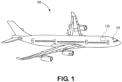
- Figure 1 illustrates a schematic view of an aircraft 100 in flight, according to an example.
- the aircraft 100 may be or include an airplane, a helicopter, an unmanned aerial vehicle (e.g., a drone), a spacecraft, or the like.
- the aircraft 100 may include a camera 110.
- the camera 110 may be coupled the aircraft 100 and/or positioned within the aircraft 100.
- the camera 110 may be configured to capture one or more images.
- the camera 110 may also or instead be configured to capture a video.
- the camera 110 may be configured to capture a continual stream of images over time (i.e. a video), and the images may be still frames taken from the video.
- the images and/or video may be transmitted to a computing system 120 on the aircraft 100.
- the computing system 120 may be located on the ground (e.g., in a control station) in communication with an on-board computing system that is on/in the aircraft 100.
- the computing system 120 may include one or more processors and a memory system.
- the memory system may include one or more non-transitory computer-readable media storing instructions that, when executed by at least one of the one or more processors, cause the computing system 120 to perform operations. The operations are described with reference to Figure 2 below.
- Figure 2 illustrates a flowchart of a method 200 for segmenting an image into a sky region and a ground region, according to an example.
- An illustrative order of the method 200 is described below. One or more steps of the method 200 may be performed in a different order, repeated, or omitted.
- the method 200 may include receiving a first image, as at 202.
- An example of the first image 300 is shown in Figure 3 .
- the first image 300 may be received by the computing system 120.
- the first image 300 may be captured by the camera 110.
- the camera 110 may be in an upright position and pointed forward such that the first image 300 includes a region of interest in the direction that the aircraft 100 is moving.
- the first image 300 may include at least a portion of the flight path of the aircraft 100.
- the first image 300 may include a ground region 310, a sky region 320, or both.
- the method 200 may also include detecting a plurality of edges (three are identified: 410, 420, 430) in the first image 300, as at 204.
- Figure 4 shows the edges 410, 420, 430 detected/identified in the first image 300.
- an "edge” refers to a point, set of points, or line (e.g., one or more pixels) in an image where the brightness changes sharply (e.g., by more than a predetermined threshold).
- the first image 300 includes more than three edges, for the sake of simplicity, only three are identified. This step may be performed by the computing system 120.
- the computing system 120 may use canny edge detection (e.g., with low hysteresis parameters) or Laplacian edge detection methods to detect the edges 410, 420, 430 in the first image 300.
- the detection may be based at least partially upon a sensitivity threshold.
- the sensitivity threshold may be increased (e.g., by a user) to detect more edges in the first image 300, or the sensitivity threshold may be decreased to detect fewer edges in the first image 300.
- the first image 300 may be binary, and pixels representing an edge 410, 420, 430 may have a value of zero, and pixels that do not represent an edge 410, 420, 430 may have a value of one, or vice versa.
- the method 200 may also include connecting one or more of the edges 410, 420, 430 in the first image 300, as at 206.
- Figure 5 shows the edges 410, 420, 430 (from Figure 4 ) after being connected to produce connected edges 510, 520, 530.
- This step may be performed by the computing system 120. More particularly, the computing system 120 may use morphological closing to produce the connected edges 510, 520, 530.
- the morphological closing may use a kernel with an area from about 2 pixels to about 200 pixels (or 2 pixels to 200 pixels), about 5 pixels to about 150 pixels (or 5 pixels to 150 pixels), about 10 pixels to about 100 pixels (or 10 pixels to 100 pixels), or about 20 pixels to about 50 pixels (or 20 pixels to 50 pixels).
- the kernel may have a shape that is substantially a square, a rectangle, a triangle, a circle, an oval, an ellipse, or the like (or that is a square, a rectangle, a triangle, a circle, an oval, an ellipse, or the like).
- the method 200 may also include identifying one or more contours (three are shown: 610, 620, 630) in the first image 300, as at 208.
- Figure 6 shows the contours 610, 620, 630 in the first image 300.
- This step may be performed by the computing system 120.
- the contours 610, 620, 630 may be identified based at least partially upon the connected edges.
- the contours 610, 620, 630 may each have an uninterrupted perimeter that is defined by the connected edges.
- the first image 300 may include a plurality of contours 610, 620, 630, and this step may include identifying the largest contour 610, which is outlined with a hatching pattern to be seen more clearly.
- the largest contour 610 may be or include the contour with the most pixels (e.g., the largest area).
- the method 200 may also include determining a convex hull 710 of the (e.g., largest) contour 610, as at 210.
- Figure 7 shows the convex hull 710 of the contour 610.
- This step may be performed by the computing system 120.
- the convex hull 710 is outlined with a hatching pattern to demonstrate and describe the step 210. In practice, such hatching may or may not be used.
- a "convex hull” refers to the smallest convex shape that (e.g., entirely) surrounds another shape (e.g., the contour 610). Thus, no line can be drawn from a first point inside of the shape to a second point inside of the shape that at some point along the line falls outside of the shape.
- the convex hull 710 represents a portion of the ground region 310 in the first image 300.
- the top 720 of the convex hull 710 may represent the horizon (e.g., between the ground region 310 and the sky region
- the method 200 may also include generating a second image 800, which includes the convex hull 710, as at 212.
- the first image 300 may be modified to produce the second image 900, which includes the convex hull 710.
- Figure 8 shows the second image 800, which includes the convex hull 710. This step may be performed by the computing system 120.
- the second image 800 may include a plurality of first (e.g., black) pixels 810 and a plurality of second (e.g., white) pixels 820.
- the first pixels 810 may represent the convex hull 710, which represents at least a part of the ground region 310.
- the second pixels 820 do not represent the convex hull 710.
- the second pixels 820 may represent the sky region 320.
- the second pixels 820 that are above the first pixels 810 may represent the sky region 320.
- some of the second pixels 820 are below the first pixels 810. As the sky region 320 cannot be below the ground region 310, this is corrected below.
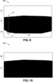
- the method 200 may also include identifying a bottom-most first pixel 911 in a column 910 in the second image 800, as at 214. This is shown in Figure 9 . This step may be performed by the computing system 120. This step may be repeated for each column in the second image 800. This may yield a bottom-most layer 920 of first pixels 810 in the second image 800. The bottom-most layer 920 is outlined with a hatching pattern to be seen more clearly.
- the method 200 may also include converting the second pixels 820 that are below the bottom-most first pixel 911 in the column 910 to first pixels 810 to produce a modified second image 1000, as at 216.
- This step may be performed by the computing system 120. This corrects the issue noted above.
- the first pixels 810 represent the ground region 310
- the second pixels 820 represent the sky region 320. There is no longer a portion of the sky region 320 that is positioned below the ground region 310.
- the modified second image 1000 may be or include a sky mask.
- a "sky mask” refers to a binary image where "false" (e.g., 0) values indicate ground pixels and "true” (e.g., 1) values indicate sky pixels.
- the method 200 may also include combining the first image 300 and at least a portion of the modified second image 1000 to produce a combined image 1100, as at 218.
- This step may be performed by the computing system 120. In at least one example, this may include overlaying at least a portion of the modified second image 1000 on the first image 300 to produce the combined image 1100.
- the portion of the modified second image 1000 that is overlaid corresponds to the ground region 310 in the first image 300 (or substantially corresponds to the ground region 310 in the first image 300).
- the portion of the modified second image 1000 may be transparent or opaque such that the first image 300 underneath may be seen.
- the portion of the modified second image 1000 is hatched to be seen more clearly.
- the portion of the modified second image 1000 may be solid such that the first image 300 underneath may not be seen.
- this step may be omitted.
- the method 200 may also include navigating (e.g., steering) the aircraft 100, as at 220.
- the aircraft 100 may be navigated (e.g., steered) based at least partially upon the second image 800, the modified second image 1000, the combined image 1100, or a combination thereof.
- the navigation may be performed (e.g., automatically) by the computing system 120. In other examples, the navigation may be performed by a user.
- the user may be in the aircraft 100 (e.g., a pilot), or the user may be on the ground and steering the aircraft 100 remotely.
- the method 200 may also or instead include detecting one or more objects, as at 222.
- This step may be performed by the computing system 120.
- the objects may be detected based at least partially upon the second image 800, the modified second image 1000, the combined image 1100, or a combination thereof.
- the second image 800, the modified second image 1000, and/or the combined image 1100 may be used as an input into a path-planning or object detection algorithm.
- the object detection algorithm may more accurately detect objects and/or detect objects with fewer false positives when the image is segmented into the sky and non-sky regions, which enables detection of the objects above the horizon (e.g., in the sky region).
- the objects detected may be or include moving objects.
- the objects may be or include other aircrafts in flight, and the aircraft 100 may be navigated in response to (e.g., to avoid) the other aircrafts in flight.
- the terms “inner” and “outer”; “up” and “down”; “upper” and “lower”; “upward” and “downward”; “upstream” and “downstream”; “above” and “below”; “inward” and “outward”; and other like terms as used herein refer to relative positions to one another and are not intended to denote a particular direction or spatial orientation.
- Couple refers to "in direct connection with” or “in connection with via one or more intermediate elements or members.”
- bonded refers to "directly bonded to” or “bonded to via one or more intermediate elements, members, or layers.”
- the term "at least one of A and B" with respect to a listing of items such as, for example, A and B, means A alone, B alone, or A and B.
- Those skilled in the art will recognize that these and other variations are possible.
- the terms “including,” “includes,” “having,” “has,” “with,” or variants thereof are used in either the detailed description and the claims, such terms are intended to be inclusive in a manner similar to the term “comprising.”
- the term “about” indicates that the value listed may be somewhat altered, as long as the alteration does not result in non-conformance of the process or structure to the intended purpose described herein.
- “exemplary” indicates the description is used as an example, rather than implying that it is an ideal.
Landscapes
- Engineering & Computer Science (AREA)
- Computer Vision & Pattern Recognition (AREA)
- Physics & Mathematics (AREA)
- General Physics & Mathematics (AREA)
- Theoretical Computer Science (AREA)
- Image Analysis (AREA)
- Image Processing (AREA)
Description
- The present disclosure is directed to sky segmentation. More particularly, the present disclosure is directed to performing sky segmentation on an image or video frame to help a vehicle determine the divide (e.g., horizon) between the ground and the sky for navigation purposes and/or to detect an object in the vehicle's field of view.
- Sky segmentation uses a machine-learning model to associate pixels in an image or video frame with the sky. Sky segmentation methods are typically either edge-based or content-based. Edge-based sky segmentation methods do not produce a complete pixel-by-pixel sky segmentation. Rather, they conclude with finding a horizon line for micro air vehicle attitude estimation. Content-based sky segmentation methods require large amounts of pixel-by-pixel hand-labeled data, and they also have a high computational cost. In addition to the foregoing shortcomings, neither method works well with limited labeled data and real-time runtime constraints.
- JUN-WEI LU ET AL, "A Modified Canny Algorithm for Detecting Sky-Sea Line in Infrared Images", Sixth International Conference on Intelligent Systems Design and Applications, 2006, pages 289 to 294, in accordance with its Abstract, states detecting sky-sea line is very important to identify targets for missile imaging guidance. As traditional Canny algorithm gives out too many edges in infrared images with sky-sea background, an modified Canny algorithm is suggested to detect the sky-sea line. In this algorithm, the Canny method is combined with a median filter, its two thresholds are designed to be adaptive based on the properties of these infrared images. A criterion is set up to distinguish the sky-sea line from other objects in an image.
- CHIU CHUNG-CHENG ET AL, "A skyline detection algorithm for use in different weather and environmental conditions", IEEE International Conference on Electro Information Technology (EIT), 2016, pages 680 to 685, in accordance with its Abstract, states skyline detection plays an important role in unmanned aerial vehicle visual flight control systems. Many studies assume that the skyline in the image is a straight line with clear edge features, but this assumption is not necessarily true under different weather and environmental conditions. For example, when it is cloudy or foggy the contrast and brightness of the image becomes weaker and the skyline is not obvious. The edge features of skyline are hard to be found in these cases. When an aircraft is flying at low altitudes, mountains, woods, or buildings become part of the skyline. Because of this, the contour of the skyline is not a straight line anymore, and the assumptions contradict the actual situation. In order to solve these problems, this paper proposes an algorithm that can detect the contour of a curving skyline in an image under different brightnesses and contrasts. Experiments are conducted using 40 images taken in different weather and environmental conditions. The results can be used as a reference for unmanned aerial vehicle flight in order to determine flight attitude.
- AHMED ET AL, "A Survey on Edge Detection based recent Marine Horizon Line Detection Methods and their Applications", 3rd International Conference on Computing, Mathematics and Engineering Technologies (iCoMET), 2020, pages 1 to 5 in accordance with its Abstract, states sea and sky boundary identification (i.e. marine horizon line detection) from a marine image is a problem of great interest for reasons such as, unmanned surface or aerial vehicle navigation, surveillance by object detection and tracking, and determining the spatial orientation of the ship. Due to the complexity of the marine environment, the problem poses its own unique challenges. In recent years, different methods have been proposed by the researchers to solve the problem. Those methods can be grouped into two categories; (i) edge detection based horizon detection, and (ii) machine learning-based horizon detection. In this paper, we present a survey on edge detection based recent marine horizon line detection methods and their applications. We have selected studies from the previous three years and discussed each study's approach to marine horizon line detection issue, the datasets used for testing purposes and its results. The authors' observations for each study are presented with a recommendation for their suitability for a specific application in the marine environment. Findings of the survey and future research directions for the researchers are also identified and presented.
- There is provided a method of sky segmentation. The method includes receiving a first image. The method also includes detecting a plurality of edges in the first image. The method also includes connecting the edges. The method also includes identifying a largest contour in the first image based at least partially upon the connected edges. The method also includes determining a convex hull of the largest contour. The method also includes generating a second image comprising the convex hull.
- A computing system is also disclosed. The computing system includes one or more processors and a memory system. The memory system includes one or more non-transitory computer-readable media storing instructions that, when executed by at least one of the one or more processors, cause the computing system to perform operations. The operations include receiving a first image. The first image is captured by a camera on an aircraft in flight. The operations also include detecting a plurality of edges in the first image based at least partially upon a threshold. The operations also include connecting the edges. The operations also include identifying a largest contour in the first image based at least partially upon the connected edges. The operations also include determining a convex hull of the largest contour. The convex hull represents a portion of a ground region in the first image. The operations also include generating a second image comprising the convex hull. A plurality of first pixels in the second image represent the convex hull, and a plurality of second pixels in the second image do not represent the convex hull.
- In other examples, the operations include receiving a first image. The first image is captured by a camera on a vehicle. The operations also include detecting a plurality of edges in the first image based at least partially upon a threshold. The operations also include connecting the edges. The edges are connected using morphological closing with a square kernel, and the morphological closing uses a kernel having an area from about 20 pixels to about 50 pixels (or from 20 pixels to 50 pixels). The operations also include identifying a largest contour in the first image based at least partially upon the connected edges. The largest contour includes a largest area. The operations also include determining a convex hull of the largest contour. The convex hull represents a portion of a ground region in the first image. The operations also include generating a second image including the convex hull. A plurality of first pixels having a first color in the second image represent the convex hull, and a plurality of second pixels having a second color in the second image do not represent the convex hull. The operations also include identifying a bottom-most first pixel in each column in the second image. The operations also include converting the second pixels that are below the bottom-most first pixel in each column to first pixels to produce a modified second image. The first pixels in the modified second image represent the ground region, and the second pixels in the modified second image represent a sky region. The operations also include combining at least a portion of the first image and at least a portion of the modified second image to produce a combined image.
- The edges may be connected using morphological closing, and wherein the morphological closing uses a kernel having an area from about 2 pixels to about 200 pixels or from 2 pixels to 200 pixels.
- An aircraft may be steered based at least partially upon the modified second image. A second aircraft may be detected in flight based at least partially upon the modified second image.
- The operations may further comprise transmitting or displaying a notification to steer the aircraft based at least partially upon the combined image, or based at least partially upon a trajectory of the second aircraft.
- The accompanying drawings, which are incorporated in and constitute a part of this specification, illustrate examples of the present teachings and together with the description, serve to explain the principles of the present teachings.
-
Figure 1 illustrates a schematic view of an aircraft in flight. -
Figure 2 illustrates a flowchart of a method for segmenting an image into a sky region and a ground region. -
Figure 3 illustrates a first image captured by a camera on the aircraft in flight. -
Figure 4 illustrates the first image with a plurality of edges identified. -
Figure 5 illustrates the first image with the edges connected. -
Figure 6 illustrates the first image with a largest contour identified. -
Figure 7 illustrates the first image with a convex hull identified. -
Figure 8 illustrates a second image including a plurality of first pixels (e.g., black pixels) representing the convex hull. -
Figure 9 illustrates the second image with a bottom-most first pixel (e.g., the bottom-most black pixel) identified in each column. -
Figure 10 illustrates the second image with second pixels (e.g., white pixels) below the bottom-most first pixel (the bottom-most black pixel) converted to first pixels (e.g., black pixels) to produce a modified second image. -
Figure 11 illustrates a combined image that includes the modified second image overlaid onto the first image. - It should be noted that some details of the figures have been simplified and are drawn to facilitate understanding rather than to maintain strict structural accuracy, detail, and scale.
- Reference will now be made in detail to the present teachings, examples of which are illustrated in the accompanying drawings. In the drawings, like reference numerals have been used throughout to designate identical elements. In the following description, reference is made to the accompanying drawings that form a part thereof, and in which is shown by way of illustration specific examples of practicing the present teachings. The following description is, therefore, merely exemplary.
- The systems and methods disclosed herein may identify/produce a boundary that approximates the separation between a ground region and a sky region in an image. The systems and methods may also mask out the non-sky (e.g., ground) region from the image to produce a sky background, which may minimize false positives of the boundary and/or detected objects. The system and methods disclosed herein may require no training data and run at or near real-time to generate a pixel-by-pixel sky segmentation map. Once the boundary has been detected, the system and method may use the boundary to help detect objects (e.g., other aircrafts, birds, etc.) and to navigate the aircraft to avoid such objects. The accuracy of the detection process may be enhanced by employing the sky segmentation technique described herein.
- The systems and methods may quickly and accurately detect non-sky regions within an image which have a nonlinear border. In addition, the systems and methods do not require labeled data to train a machine-learning (ML) model. The systems and methods segment non-sky regions pixel-by-pixel, rather than by finding a horizon line and dividing the image into "above horizon" and "below horizon."
- The camera may be fixed to the aircraft at a defined position relative to the aircraft with its field of view directed toward a region of interest (e.g., forward and/or in the direction that the aircraft is travelling). The sky regions may be entirely contained above non-sky regions. The non-sky regions may contain more edge sections than sky regions do. The sky and non-sky regions are separated by a horizon: a moderately straight line which traverses most to all of the width of the image. Examples of the system and method may divide the image into sky and non-sky regions.
-
Figure 1 illustrates a schematic view of anaircraft 100 in flight, according to an example. Theaircraft 100 may be or include an airplane, a helicopter, an unmanned aerial vehicle (e.g., a drone), a spacecraft, or the like. Theaircraft 100 may include acamera 110. Thecamera 110 may be coupled theaircraft 100 and/or positioned within theaircraft 100. Thecamera 110 may be configured to capture one or more images. Thecamera 110 may also or instead be configured to capture a video. In some examples, thecamera 110 may be configured to capture a continual stream of images over time (i.e. a video), and the images may be still frames taken from the video. - The images and/or video may be transmitted to a
computing system 120 on theaircraft 100. In other examples, thecomputing system 120 may be located on the ground (e.g., in a control station) in communication with an on-board computing system that is on/in theaircraft 100. Thecomputing system 120 may include one or more processors and a memory system. The memory system may include one or more non-transitory computer-readable media storing instructions that, when executed by at least one of the one or more processors, cause thecomputing system 120 to perform operations. The operations are described with reference toFigure 2 below. -
Figure 2 illustrates a flowchart of amethod 200 for segmenting an image into a sky region and a ground region, according to an example. An illustrative order of themethod 200 is described below. One or more steps of themethod 200 may be performed in a different order, repeated, or omitted. - The
method 200 may include receiving a first image, as at 202. An example of thefirst image 300 is shown inFigure 3 . Thefirst image 300 may be received by thecomputing system 120. As mentioned above, thefirst image 300 may be captured by thecamera 110. Thecamera 110 may be in an upright position and pointed forward such that thefirst image 300 includes a region of interest in the direction that theaircraft 100 is moving. Thus, thefirst image 300 may include at least a portion of the flight path of theaircraft 100. Thefirst image 300 may include aground region 310, asky region 320, or both. - The
method 200 may also include detecting a plurality of edges (three are identified: 410, 420, 430) in thefirst image 300, as at 204.Figure 4 shows theedges first image 300. As used herein, an "edge" refers to a point, set of points, or line (e.g., one or more pixels) in an image where the brightness changes sharply (e.g., by more than a predetermined threshold). Although thefirst image 300 includes more than three edges, for the sake of simplicity, only three are identified. This step may be performed by thecomputing system 120. More particularly, thecomputing system 120 may use canny edge detection (e.g., with low hysteresis parameters) or Laplacian edge detection methods to detect theedges first image 300. In at least one example, the detection may be based at least partially upon a sensitivity threshold. For example, the sensitivity threshold may be increased (e.g., by a user) to detect more edges in thefirst image 300, or the sensitivity threshold may be decreased to detect fewer edges in thefirst image 300. In at least one example, thefirst image 300 may be binary, and pixels representing anedge edge - The
method 200 may also include connecting one or more of theedges first image 300, as at 206.Figure 5 shows theedges Figure 4 ) after being connected to produceconnected edges computing system 120. More particularly, thecomputing system 120 may use morphological closing to produce theconnected edges - The
method 200 may also include identifying one or more contours (three are shown: 610, 620, 630) in thefirst image 300, as at 208.Figure 6 shows thecontours first image 300. This step may be performed by thecomputing system 120. Thecontours contours first image 300 may include a plurality ofcontours largest contour 610, which is outlined with a hatching pattern to be seen more clearly. Thelargest contour 610 may be or include the contour with the most pixels (e.g., the largest area). - The
method 200 may also include determining aconvex hull 710 of the (e.g., largest)contour 610, as at 210.Figure 7 shows theconvex hull 710 of thecontour 610. This step may be performed by thecomputing system 120. Theconvex hull 710 is outlined with a hatching pattern to demonstrate and describe thestep 210. In practice, such hatching may or may not be used. As used herein, a "convex hull" refers to the smallest convex shape that (e.g., entirely) surrounds another shape (e.g., the contour 610). Thus, no line can be drawn from a first point inside of the shape to a second point inside of the shape that at some point along the line falls outside of the shape. Theconvex hull 710 represents a portion of theground region 310 in thefirst image 300. The top 720 of theconvex hull 710 may represent the horizon (e.g., between theground region 310 and the sky region 320). - The
method 200 may also include generating asecond image 800, which includes theconvex hull 710, as at 212. Alternatively, thefirst image 300 may be modified to produce the second image 900, which includes theconvex hull 710.Figure 8 shows thesecond image 800, which includes theconvex hull 710. This step may be performed by thecomputing system 120. Thesecond image 800 may include a plurality of first (e.g., black)pixels 810 and a plurality of second (e.g., white)pixels 820. Thefirst pixels 810 may represent theconvex hull 710, which represents at least a part of theground region 310. Thesecond pixels 820 do not represent theconvex hull 710. Instead, at least a portion of thesecond pixels 820 may represent thesky region 320. For example, thesecond pixels 820 that are above thefirst pixels 810 may represent thesky region 320. However, as may be seen, some of thesecond pixels 820 are below thefirst pixels 810. As thesky region 320 cannot be below theground region 310, this is corrected below. - The
method 200 may also include identifying a bottom-mostfirst pixel 911 in acolumn 910 in thesecond image 800, as at 214. This is shown inFigure 9 . This step may be performed by thecomputing system 120. This step may be repeated for each column in thesecond image 800. This may yield abottom-most layer 920 offirst pixels 810 in thesecond image 800. Thebottom-most layer 920 is outlined with a hatching pattern to be seen more clearly. - The
method 200 may also include converting thesecond pixels 820 that are below the bottom-mostfirst pixel 911 in thecolumn 910 tofirst pixels 810 to produce a modifiedsecond image 1000, as at 216. This is shown inFigure 10 . This step may be performed by thecomputing system 120. This corrects the issue noted above. Now, thefirst pixels 810 represent theground region 310, and thesecond pixels 820 represent thesky region 320. There is no longer a portion of thesky region 320 that is positioned below theground region 310. The modifiedsecond image 1000 may be or include a sky mask. As used herein, a "sky mask" refers to a binary image where "false" (e.g., 0) values indicate ground pixels and "true" (e.g., 1) values indicate sky pixels. - In some examples, the
method 200 may also include combining thefirst image 300 and at least a portion of the modifiedsecond image 1000 to produce a combinedimage 1100, as at 218. This is shown inFigure 11 . This step may be performed by thecomputing system 120. In at least one example, this may include overlaying at least a portion of the modifiedsecond image 1000 on thefirst image 300 to produce the combinedimage 1100. The portion of the modifiedsecond image 1000 that is overlaid corresponds to theground region 310 in the first image 300 (or substantially corresponds to theground region 310 in the first image 300). As shown, the portion of the modifiedsecond image 1000 may be transparent or opaque such that thefirst image 300 underneath may be seen. InFigure 11 , the portion of the modifiedsecond image 1000 is hatched to be seen more clearly. In other examples, the portion of the modifiedsecond image 1000 may be solid such that thefirst image 300 underneath may not be seen. In yet other examples, this step may be omitted. - The
method 200 may also include navigating (e.g., steering) theaircraft 100, as at 220. Theaircraft 100 may be navigated (e.g., steered) based at least partially upon thesecond image 800, the modifiedsecond image 1000, the combinedimage 1100, or a combination thereof. The navigation may be performed (e.g., automatically) by thecomputing system 120. In other examples, the navigation may be performed by a user. The user may be in the aircraft 100 (e.g., a pilot), or the user may be on the ground and steering theaircraft 100 remotely. - In other examples, the
method 200 may also or instead include detecting one or more objects, as at 222. This step may be performed by thecomputing system 120. The objects may be detected based at least partially upon thesecond image 800, the modifiedsecond image 1000, the combinedimage 1100, or a combination thereof. For example, thesecond image 800, the modifiedsecond image 1000, and/or the combinedimage 1100 may be used as an input into a path-planning or object detection algorithm. The object detection algorithm may more accurately detect objects and/or detect objects with fewer false positives when the image is segmented into the sky and non-sky regions, which enables detection of the objects above the horizon (e.g., in the sky region). The objects detected may be or include moving objects. For example, the objects may be or include other aircrafts in flight, and theaircraft 100 may be navigated in response to (e.g., to avoid) the other aircrafts in flight. - As used herein, the terms "inner" and "outer"; "up" and "down"; "upper" and "lower"; "upward" and "downward"; "upstream" and "downstream"; "above" and "below"; "inward" and "outward"; and other like terms as used herein refer to relative positions to one another and are not intended to denote a particular direction or spatial orientation. The terms "couple," "coupled," "connect," "connection," "connected," "in connection with," and "connecting" refer to "in direct connection with" or "in connection with via one or more intermediate elements or members." Similarly, the terms "bonded" and "bonding" refer to "directly bonded to" or "bonded to via one or more intermediate elements, members, or layers."
- Notwithstanding that the numerical ranges and parameters setting forth the broad scope of the disclosure are approximations, the numerical values set forth in the specific examples are reported as precisely as possible. Any numerical value, however, inherently contains certain errors necessarily resulting from the standard deviation found in their respective testing measurements. Moreover, all ranges disclosed herein are to be understood to encompass any and all sub-ranges subsumed therein.
- While the present teachings have been illustrated with respect to one or more examples, alterations and/or modifications can be made to the illustrated examples without departing from the scope of the appended claims. In addition, while a particular feature of the present teachings may have been disclosed with respect to only one of several examples, such feature may be combined with one or more other features of the other examplesas may be desired and advantageous for any given or particular function. As used herein, the terms "a", "an", and "the" may refer to one or more elements or parts of elements. As used herein, the terms "first" and "second" may refer to two different elements or parts of elements. As used herein, the term "at least one of A and B" with respect to a listing of items such as, for example, A and B, means A alone, B alone, or A and B. Those skilled in the art will recognize that these and other variations are possible. Furthermore, to the extent that the terms "including," "includes," "having," "has," "with," or variants thereof are used in either the detailed description and the claims, such terms are intended to be inclusive in a manner similar to the term "comprising." Further, in the discussion and claims herein, the term "about" indicates that the value listed may be somewhat altered, as long as the alteration does not result in non-conformance of the process or structure to the intended purpose described herein. Finally, "exemplary" indicates the description is used as an example, rather than implying that it is an ideal.
Claims (15)
- A method of sky segmentation (200), comprisingreceiving a first image (300);detecting a plurality of edges (410, 420, 430) in the first image (300);connecting the edges (410, 420, 430);identifying a largest contour (610) in the first image (300) based at least partially upon the connected edges (410, 420, 430);determining a convex hull (710) of the largest contour (610); andgenerating a second image (800) comprising the convex hull (710).
- The method of claim 1, wherein the first image (300) is captured by a camera (110) on a vehicle.
- The method of claim 2, wherein the vehicle is an aircraft (100) in flight and, optionally, the method further comprises navigating the aircraft (100) based at least partially upon the second image (1000).
- The method of any preceding claim, comprising detecting the plurality of edges (410, 420, 430) in the first image (300) based at least partially upon a threshold.
- The method of any preceding claim, wherein identifying the largest contour (610) in the first image (300) comprises identifying the largest contour (610) in the first image (300) based at least partially upon the connected edges (410, 420, 430) and, optionally, wherein the largest contour (610) comprises the largest area.
- The method of any preceding claim, comprising connecting the edges (410, 420, 430) using morphological closing, and wherein the morphological closing uses a kernel, optionally a square kernel, with (a) the kernel having an area from about 10 pixels to about 100 pixels, optionally from about 20 pixels to about 50 pixels, or (b) the kernel having an area from 10 pixels to 100 pixels, optionally from 20 pixels to 50 pixels.
- The method of any preceding claim, wherein the convex hull (710) represents a portion of a ground region (310) in the first image (300).
- The method of claim 7, wherein a plurality of first pixels (810) in the second image (800) represent the convex hull (710) and a plurality of second pixels (820) in the second image (800) do not represent the convex hull (710).
- The method of claim 8, further comprising:identifying a bottom-most first pixel (911) in each column (910) in the second image (800); andconverting the second pixels (820) that are below the bottom-most first pixel (910) in each column (910) to first pixels (810) to produce a modified second image (1000), wherein:
the first pixels (810) in the modified second image (1000) represent the ground region (310), and the second pixels (820) in the modified second image (1000) represent a sky region (320). - The method of claim 9, wherein generating the modified second image (800) comprises generating the plurality of first pixels (810) that represent the ground region (310) to have a first color and generating the plurality of second pixels (820) represent the sky region (320) to have a second color.
- The method of claim 10, comprising combining at least a portion of the first image (300) and at least a portion of the modified second image (1000) to produce a combined image (1100).
- The method of claim 11, wherein combining at least a portion of the first image (300) and at least a portion of the modified second image (1000) to produce the combined image (1100) comprises overlaying a portion of the modified second image (1000) that corresponds to the ground region (310) on the first image (300) and, optionally, wherein the modified second image (1000) is at least partially transparent when overlaid on the first image (300).
- The method of any of claims 11 or 12, further comprising detecting an object, optionally an object in space, based at least partially upon the combined image (1100).
- A computing system (120) comprising:one or more processors; anda memory system comprising one or more non-transitory computer-readable media storing instructions that, when executed by at least one of the one or more processors, cause the computing system to perform the method of any preceding claim, or an aircraft comprising such a computing system.
- A computer program comprising instructions that, when executed by a computer processor, cause the computer processor to perform the method of any of claims 1-13, or computer readable medium having stored therein such a computer program.
Applications Claiming Priority (1)
| Application Number | Priority Date | Filing Date | Title |
|---|---|---|---|
| US202063048799P | 2020-07-07 | 2020-07-07 |
Publications (2)
| Publication Number | Publication Date |
|---|---|
| EP3937131A1 EP3937131A1 (en) | 2022-01-12 |
| EP3937131B1 true EP3937131B1 (en) | 2025-02-12 |
Family
ID=75539195
Family Applications (1)
| Application Number | Title | Priority Date | Filing Date |
|---|---|---|---|
| EP21168617.5A Active EP3937131B1 (en) | 2020-07-07 | 2021-04-15 | Sky segmentor using canny lines |
Country Status (3)
| Country | Link |
|---|---|
| US (1) | US11893743B2 (en) |
| EP (1) | EP3937131B1 (en) |
| CN (1) | CN113971790A (en) |
Families Citing this family (2)
| Publication number | Priority date | Publication date | Assignee | Title |
|---|---|---|---|---|
| DE102022119751A1 (en) * | 2022-08-05 | 2024-02-08 | Connaught Electronics Ltd. | Determining an area of interest from camera images |
| US20250251254A1 (en) * | 2024-02-05 | 2025-08-07 | The Boeing Company | Computing contour map using topological cases and classifier cases |
Family Cites Families (5)
| Publication number | Priority date | Publication date | Assignee | Title |
|---|---|---|---|---|
| US9792522B2 (en) * | 2015-12-01 | 2017-10-17 | Bloomsky, Inc. | Weather information extraction using sequential images |
| EP3293672A1 (en) * | 2016-09-07 | 2018-03-14 | Malvern Panalytical Limited | Particle boundary identification |
| CA3073713A1 (en) * | 2017-08-25 | 2019-02-28 | The Board Of Trustees Of The University Of Illinois | Apparatus and method for agricultural data collection and agricultural operations |
| CN108596849B (en) * | 2018-04-23 | 2021-11-23 | 南京邮电大学 | Single image defogging method based on sky region segmentation |
| CN111209908B (en) * | 2019-12-31 | 2023-07-14 | 深圳奇迹智慧网络有限公司 | Method, device, storage medium and computer equipment for updating annotation frame |
-
2021
- 2021-04-09 US US17/227,050 patent/US11893743B2/en active Active
- 2021-04-15 EP EP21168617.5A patent/EP3937131B1/en active Active
- 2021-07-06 CN CN202110764460.1A patent/CN113971790A/en active Pending
Also Published As
| Publication number | Publication date |
|---|---|
| CN113971790A (en) | 2022-01-25 |
| US11893743B2 (en) | 2024-02-06 |
| EP3937131A1 (en) | 2022-01-12 |
| US20220012893A1 (en) | 2022-01-13 |
Similar Documents
| Publication | Publication Date | Title |
|---|---|---|
| US11748898B2 (en) | Methods and system for infrared tracking | |
| US12198418B2 (en) | System and method for measuring the distance to an object in water | |
| Patruno et al. | A vision-based approach for unmanned aerial vehicle landing | |
| KR100985195B1 (en) | System for automatic taking off and landing of image based | |
| US12277744B2 (en) | System and method for detecting and tracking an object | |
| US11893743B2 (en) | Sky segmentor using canny lines | |
| US20180012060A1 (en) | Detecting and ranging cloud features | |
| Dolph et al. | Sense and avoid for small unmanned aircraft systems | |
| Ajith et al. | Robust method to detect and track the runway during aircraft landing using colour segmentation and runway features | |
| CN120964057A (en) | Mooring unmanned aerial vehicle heel fly and accurate landing target system and method | |
| KR101050730B1 (en) | Unmanned aerial vehicle position control device based on runway auxiliary line and its control method | |
| EP3937130B1 (en) | System and method for performing sky-segmentation | |
| Chiu et al. | Vision-only automatic flight control for small UAVs | |
| US12147496B1 (en) | Automatic generation of training data for instance segmentation algorithms | |
| Chiu et al. | A skyline detection algorithm for use in different weather and environmental conditions | |
| Samaranayake et al. | Detecting water in visual image streams from UAV with flight constraints | |
| US11893740B2 (en) | Moving object detection from a moving camera | |
| Etnubarhi et al. | Assessing YOLOv8 Performance and Limitations in Aircraft and Ship Detection from Satellite Images | |
| EP4603991A1 (en) | Airport scene perception | |
| US20220309786A1 (en) | Method for training a supervised artificial intelligence intended to identify a predetermined object in the environment of an aircraft | |
| Nikhil et al. | Vision Based Landing Pad Detection for Autonomous Landing of Quadcopter | |
| CN120544086A (en) | A method and system for identifying unmanned aerial vehicle targets at low altitudes in cities | |
| Chen et al. | Research on Drogue Detection Algorithm for Aerial Refueling (IEEE/CSAA GNCC) | |
| Erdman | SeaVipers-Computer Vision and Inertial Position Reference Sensor System (CVIPRSS) | |
| Rawashdeh et al. | Altitude and attitude estimation from aerial fisheye video |
Legal Events
| Date | Code | Title | Description |
|---|---|---|---|
| PUAI | Public reference made under article 153(3) epc to a published international application that has entered the european phase |
Free format text: ORIGINAL CODE: 0009012 |
|
| STAA | Information on the status of an ep patent application or granted ep patent |
Free format text: STATUS: THE APPLICATION HAS BEEN PUBLISHED |
|
| AK | Designated contracting states |
Kind code of ref document: A1 Designated state(s): AL AT BE BG CH CY CZ DE DK EE ES FI FR GB GR HR HU IE IS IT LI LT LU LV MC MK MT NL NO PL PT RO RS SE SI SK SM TR |
|
| B565 | Issuance of search results under rule 164(2) epc |
Effective date: 20211001 |
|
| STAA | Information on the status of an ep patent application or granted ep patent |
Free format text: STATUS: REQUEST FOR EXAMINATION WAS MADE |
|
| 17P | Request for examination filed |
Effective date: 20220712 |
|
| RBV | Designated contracting states (corrected) |
Designated state(s): AL AT BE BG CH CY CZ DE DK EE ES FI FR GB GR HR HU IE IS IT LI LT LU LV MC MK MT NL NO PL PT RO RS SE SI SK SM TR |
|
| RIC1 | Information provided on ipc code assigned before grant |
Ipc: G06T 7/181 20170101ALI20240807BHEP Ipc: G06T 7/155 20170101ALI20240807BHEP Ipc: G06T 7/136 20170101ALI20240807BHEP Ipc: G06T 7/12 20170101AFI20240807BHEP |
|
| GRAP | Despatch of communication of intention to grant a patent |
Free format text: ORIGINAL CODE: EPIDOSNIGR1 |
|
| STAA | Information on the status of an ep patent application or granted ep patent |
Free format text: STATUS: GRANT OF PATENT IS INTENDED |
|
| INTG | Intention to grant announced |
Effective date: 20240913 |
|
| P01 | Opt-out of the competence of the unified patent court (upc) registered |
Free format text: CASE NUMBER: APP_54230/2024 Effective date: 20241001 |
|
| GRAS | Grant fee paid |
Free format text: ORIGINAL CODE: EPIDOSNIGR3 |
|
| GRAA | (expected) grant |
Free format text: ORIGINAL CODE: 0009210 |
|
| STAA | Information on the status of an ep patent application or granted ep patent |
Free format text: STATUS: THE PATENT HAS BEEN GRANTED |
|
| AK | Designated contracting states |
Kind code of ref document: B1 Designated state(s): AL AT BE BG CH CY CZ DE DK EE ES FI FR GB GR HR HU IE IS IT LI LT LU LV MC MK MT NL NO PL PT RO RS SE SI SK SM TR |
|
| REG | Reference to a national code |
Ref country code: GB Ref legal event code: FG4D |
|
| REG | Reference to a national code |
Ref country code: CH Ref legal event code: EP |
|
| REG | Reference to a national code |
Ref country code: DE Ref legal event code: R096 Ref document number: 602021025858 Country of ref document: DE |
|
| REG | Reference to a national code |
Ref country code: IE Ref legal event code: FG4D |
|
| REG | Reference to a national code |
Ref country code: NL Ref legal event code: MP Effective date: 20250212 |
|
| PG25 | Lapsed in a contracting state [announced via postgrant information from national office to epo] |
Ref country code: RS Free format text: LAPSE BECAUSE OF FAILURE TO SUBMIT A TRANSLATION OF THE DESCRIPTION OR TO PAY THE FEE WITHIN THE PRESCRIBED TIME-LIMIT Effective date: 20250512 |
|
| PG25 | Lapsed in a contracting state [announced via postgrant information from national office to epo] |
Ref country code: FI Free format text: LAPSE BECAUSE OF FAILURE TO SUBMIT A TRANSLATION OF THE DESCRIPTION OR TO PAY THE FEE WITHIN THE PRESCRIBED TIME-LIMIT Effective date: 20250212 |
|
| PG25 | Lapsed in a contracting state [announced via postgrant information from national office to epo] |
Ref country code: PL Free format text: LAPSE BECAUSE OF FAILURE TO SUBMIT A TRANSLATION OF THE DESCRIPTION OR TO PAY THE FEE WITHIN THE PRESCRIBED TIME-LIMIT Effective date: 20250212 |
|
| PGFP | Annual fee paid to national office [announced via postgrant information from national office to epo] |
Ref country code: DE Payment date: 20250429 Year of fee payment: 5 |
|
| PG25 | Lapsed in a contracting state [announced via postgrant information from national office to epo] |
Ref country code: ES Free format text: LAPSE BECAUSE OF FAILURE TO SUBMIT A TRANSLATION OF THE DESCRIPTION OR TO PAY THE FEE WITHIN THE PRESCRIBED TIME-LIMIT Effective date: 20250212 |
|
| PGFP | Annual fee paid to national office [announced via postgrant information from national office to epo] |
Ref country code: GB Payment date: 20250428 Year of fee payment: 5 |
|
| REG | Reference to a national code |
Ref country code: LT Ref legal event code: MG9D |
|
| PG25 | Lapsed in a contracting state [announced via postgrant information from national office to epo] |
Ref country code: NO Free format text: LAPSE BECAUSE OF FAILURE TO SUBMIT A TRANSLATION OF THE DESCRIPTION OR TO PAY THE FEE WITHIN THE PRESCRIBED TIME-LIMIT Effective date: 20250512 Ref country code: IS Free format text: LAPSE BECAUSE OF FAILURE TO SUBMIT A TRANSLATION OF THE DESCRIPTION OR TO PAY THE FEE WITHIN THE PRESCRIBED TIME-LIMIT Effective date: 20250612 |
|
| PG25 | Lapsed in a contracting state [announced via postgrant information from national office to epo] |
Ref country code: NL Free format text: LAPSE BECAUSE OF FAILURE TO SUBMIT A TRANSLATION OF THE DESCRIPTION OR TO PAY THE FEE WITHIN THE PRESCRIBED TIME-LIMIT Effective date: 20250212 |
|
| PG25 | Lapsed in a contracting state [announced via postgrant information from national office to epo] |
Ref country code: HR Free format text: LAPSE BECAUSE OF FAILURE TO SUBMIT A TRANSLATION OF THE DESCRIPTION OR TO PAY THE FEE WITHIN THE PRESCRIBED TIME-LIMIT Effective date: 20250212 |
|
| PG25 | Lapsed in a contracting state [announced via postgrant information from national office to epo] |
Ref country code: PT Free format text: LAPSE BECAUSE OF FAILURE TO SUBMIT A TRANSLATION OF THE DESCRIPTION OR TO PAY THE FEE WITHIN THE PRESCRIBED TIME-LIMIT Effective date: 20250612 Ref country code: LV Free format text: LAPSE BECAUSE OF FAILURE TO SUBMIT A TRANSLATION OF THE DESCRIPTION OR TO PAY THE FEE WITHIN THE PRESCRIBED TIME-LIMIT Effective date: 20250212 |
|
| PGFP | Annual fee paid to national office [announced via postgrant information from national office to epo] |
Ref country code: FR Payment date: 20250425 Year of fee payment: 5 |
|
| PG25 | Lapsed in a contracting state [announced via postgrant information from national office to epo] |
Ref country code: GR Free format text: LAPSE BECAUSE OF FAILURE TO SUBMIT A TRANSLATION OF THE DESCRIPTION OR TO PAY THE FEE WITHIN THE PRESCRIBED TIME-LIMIT Effective date: 20250513 Ref country code: BG Free format text: LAPSE BECAUSE OF FAILURE TO SUBMIT A TRANSLATION OF THE DESCRIPTION OR TO PAY THE FEE WITHIN THE PRESCRIBED TIME-LIMIT Effective date: 20250212 |
|
| REG | Reference to a national code |
Ref country code: AT Ref legal event code: MK05 Ref document number: 1766809 Country of ref document: AT Kind code of ref document: T Effective date: 20250212 |
|
| PG25 | Lapsed in a contracting state [announced via postgrant information from national office to epo] |
Ref country code: SE Free format text: LAPSE BECAUSE OF FAILURE TO SUBMIT A TRANSLATION OF THE DESCRIPTION OR TO PAY THE FEE WITHIN THE PRESCRIBED TIME-LIMIT Effective date: 20250212 |
|
| PG25 | Lapsed in a contracting state [announced via postgrant information from national office to epo] |
Ref country code: SM Free format text: LAPSE BECAUSE OF FAILURE TO SUBMIT A TRANSLATION OF THE DESCRIPTION OR TO PAY THE FEE WITHIN THE PRESCRIBED TIME-LIMIT Effective date: 20250212 |
|
| PG25 | Lapsed in a contracting state [announced via postgrant information from national office to epo] |
Ref country code: DK Free format text: LAPSE BECAUSE OF FAILURE TO SUBMIT A TRANSLATION OF THE DESCRIPTION OR TO PAY THE FEE WITHIN THE PRESCRIBED TIME-LIMIT Effective date: 20250212 |
|
| PG25 | Lapsed in a contracting state [announced via postgrant information from national office to epo] |
Ref country code: IT Free format text: LAPSE BECAUSE OF FAILURE TO SUBMIT A TRANSLATION OF THE DESCRIPTION OR TO PAY THE FEE WITHIN THE PRESCRIBED TIME-LIMIT Effective date: 20250212 |
|
| PG25 | Lapsed in a contracting state [announced via postgrant information from national office to epo] |
Ref country code: AT Free format text: LAPSE BECAUSE OF FAILURE TO SUBMIT A TRANSLATION OF THE DESCRIPTION OR TO PAY THE FEE WITHIN THE PRESCRIBED TIME-LIMIT Effective date: 20250212 |
|
| PG25 | Lapsed in a contracting state [announced via postgrant information from national office to epo] |
Ref country code: CZ Free format text: LAPSE BECAUSE OF FAILURE TO SUBMIT A TRANSLATION OF THE DESCRIPTION OR TO PAY THE FEE WITHIN THE PRESCRIBED TIME-LIMIT Effective date: 20250212 Ref country code: EE Free format text: LAPSE BECAUSE OF FAILURE TO SUBMIT A TRANSLATION OF THE DESCRIPTION OR TO PAY THE FEE WITHIN THE PRESCRIBED TIME-LIMIT Effective date: 20250212 |
|
| PG25 | Lapsed in a contracting state [announced via postgrant information from national office to epo] |
Ref country code: RO Free format text: LAPSE BECAUSE OF FAILURE TO SUBMIT A TRANSLATION OF THE DESCRIPTION OR TO PAY THE FEE WITHIN THE PRESCRIBED TIME-LIMIT Effective date: 20250212 |
|
| PG25 | Lapsed in a contracting state [announced via postgrant information from national office to epo] |
Ref country code: SK Free format text: LAPSE BECAUSE OF FAILURE TO SUBMIT A TRANSLATION OF THE DESCRIPTION OR TO PAY THE FEE WITHIN THE PRESCRIBED TIME-LIMIT Effective date: 20250212 |
|
| REG | Reference to a national code |
Ref country code: DE Ref legal event code: R097 Ref document number: 602021025858 Country of ref document: DE |
|
| REG | Reference to a national code |
Ref country code: CH Ref legal event code: H13 Free format text: ST27 STATUS EVENT CODE: U-0-0-H10-H13 (AS PROVIDED BY THE NATIONAL OFFICE) Effective date: 20251125 |
|
| PG25 | Lapsed in a contracting state [announced via postgrant information from national office to epo] |
Ref country code: LU Free format text: LAPSE BECAUSE OF NON-PAYMENT OF DUE FEES Effective date: 20250415 |
|
| PLBE | No opposition filed within time limit |
Free format text: ORIGINAL CODE: 0009261 |
|
| STAA | Information on the status of an ep patent application or granted ep patent |
Free format text: STATUS: NO OPPOSITION FILED WITHIN TIME LIMIT |
|
| PG25 | Lapsed in a contracting state [announced via postgrant information from national office to epo] |
Ref country code: MC Free format text: LAPSE BECAUSE OF FAILURE TO SUBMIT A TRANSLATION OF THE DESCRIPTION OR TO PAY THE FEE WITHIN THE PRESCRIBED TIME-LIMIT Effective date: 20250212 |
|
| REG | Reference to a national code |
Ref country code: BE Ref legal event code: MM Effective date: 20250430 |
|
| PG25 | Lapsed in a contracting state [announced via postgrant information from national office to epo] |
Ref country code: BE Free format text: LAPSE BECAUSE OF NON-PAYMENT OF DUE FEES Effective date: 20250430 |
|
| PG25 | Lapsed in a contracting state [announced via postgrant information from national office to epo] |
Ref country code: CH Free format text: LAPSE BECAUSE OF NON-PAYMENT OF DUE FEES Effective date: 20250430 |
|
| 26N | No opposition filed |
Effective date: 20251113 |
|
| PG25 | Lapsed in a contracting state [announced via postgrant information from national office to epo] |
Ref country code: IE Free format text: LAPSE BECAUSE OF NON-PAYMENT OF DUE FEES Effective date: 20250415 |