EP3937117A1 - Method and system for transmitting and/or receiving messages via identification - Google Patents
Method and system for transmitting and/or receiving messages via identification Download PDFInfo
- Publication number
- EP3937117A1 EP3937117A1 EP21194998.7A EP21194998A EP3937117A1 EP 3937117 A1 EP3937117 A1 EP 3937117A1 EP 21194998 A EP21194998 A EP 21194998A EP 3937117 A1 EP3937117 A1 EP 3937117A1
- Authority
- EP
- European Patent Office
- Prior art keywords
- channel
- code
- message
- identification
- compound
- Prior art date
- Legal status (The legal status is an assumption and is not a legal conclusion. Google has not performed a legal analysis and makes no representation as to the accuracy of the status listed.)
- Granted
Links
Images



Classifications
-
- H—ELECTRICITY
- H04—ELECTRIC COMMUNICATION TECHNIQUE
- H04L—TRANSMISSION OF DIGITAL INFORMATION, e.g. TELEGRAPHIC COMMUNICATION
- H04L63/00—Network architectures or network communication protocols for network security
- H04L63/14—Network architectures or network communication protocols for network security for detecting or protecting against malicious traffic
- H04L63/1441—Countermeasures against malicious traffic
- H04L63/1475—Passive attacks, e.g. eavesdropping or listening without modification of the traffic monitored
-
- H—ELECTRICITY
- H03—ELECTRONIC CIRCUITRY
- H03M—CODING; DECODING; CODE CONVERSION IN GENERAL
- H03M13/00—Coding, decoding or code conversion, for error detection or error correction; Coding theory basic assumptions; Coding bounds; Error probability evaluation methods; Channel models; Simulation or testing of codes
- H03M13/35—Unequal or adaptive error protection, e.g. by providing a different level of protection according to significance of source information or by adapting the coding according to the change of transmission channel characteristics
- H03M13/353—Adaptation to the channel
-
- H—ELECTRICITY
- H03—ELECTRONIC CIRCUITRY
- H03M—CODING; DECODING; CODE CONVERSION IN GENERAL
- H03M13/00—Coding, decoding or code conversion, for error detection or error correction; Coding theory basic assumptions; Coding bounds; Error probability evaluation methods; Channel models; Simulation or testing of codes
- H03M13/37—Decoding methods or techniques, not specific to the particular type of coding provided for in groups H03M13/03 - H03M13/35
- H03M13/3707—Adaptive decoding and hybrid decoding, e.g. decoding methods or techniques providing more than one decoding algorithm for one code
-
- H—ELECTRICITY
- H03—ELECTRONIC CIRCUITRY
- H03M—CODING; DECODING; CODE CONVERSION IN GENERAL
- H03M13/00—Coding, decoding or code conversion, for error detection or error correction; Coding theory basic assumptions; Coding bounds; Error probability evaluation methods; Channel models; Simulation or testing of codes
- H03M13/03—Error detection or forward error correction by redundancy in data representation, i.e. code words containing more digits than the source words
- H03M13/05—Error detection or forward error correction by redundancy in data representation, i.e. code words containing more digits than the source words using block codes, i.e. a predetermined number of check bits joined to a predetermined number of information bits
- H03M13/11—Error detection or forward error correction by redundancy in data representation, i.e. code words containing more digits than the source words using block codes, i.e. a predetermined number of check bits joined to a predetermined number of information bits using multiple parity bits
- H03M13/1102—Codes on graphs and decoding on graphs, e.g. low-density parity check [LDPC] codes
-
- H—ELECTRICITY
- H03—ELECTRONIC CIRCUITRY
- H03M—CODING; DECODING; CODE CONVERSION IN GENERAL
- H03M13/00—Coding, decoding or code conversion, for error detection or error correction; Coding theory basic assumptions; Coding bounds; Error probability evaluation methods; Channel models; Simulation or testing of codes
- H03M13/03—Error detection or forward error correction by redundancy in data representation, i.e. code words containing more digits than the source words
- H03M13/05—Error detection or forward error correction by redundancy in data representation, i.e. code words containing more digits than the source words using block codes, i.e. a predetermined number of check bits joined to a predetermined number of information bits
- H03M13/13—Linear codes
-
- H—ELECTRICITY
- H03—ELECTRONIC CIRCUITRY
- H03M—CODING; DECODING; CODE CONVERSION IN GENERAL
- H03M13/00—Coding, decoding or code conversion, for error detection or error correction; Coding theory basic assumptions; Coding bounds; Error probability evaluation methods; Channel models; Simulation or testing of codes
- H03M13/29—Coding, decoding or code conversion, for error detection or error correction; Coding theory basic assumptions; Coding bounds; Error probability evaluation methods; Channel models; Simulation or testing of codes combining two or more codes or code structures, e.g. product codes, generalised product codes, concatenated codes, inner and outer codes
- H03M13/2957—Turbo codes and decoding
Definitions
- the present invention refers to a method and a system for transmitting and/or receiving messages via identification, in particular in an environment of registered transmitting and receiving sites.
- a method of transmitting and/or receiving messages in an environment of registered transmitting sites and receiving sites via identification is provided.
- a respective message is selected from a fixed set of messages - which may in particular be finite or at least countable - and which is sent and/or received over a compound channel via identification.
- the compound channel - as a set of channels and ruled by a state variable - is given and used based on a compound code by using a stochastic encoder.
- an identification code may be used which is generated based on said compound code by using a stochastic encoder.
- an identification code or said identification code mentioned before may be used which is generated based on said compound code by using a stochastic encoder or said stochastic encoder.
- said stochastic encoder may be configured in order to randomly assign thereto as a code for the message a value of a random variable within an assigned probability distribution, and the assigned code may be transmitted via the compound channel.
- a receiving site it may be checked whether a respective code received at the receiving site and referred to as a value of a random variable is within a probability distribution assigned to a respective message selected at the receiving site.
- the identification paradigm is realized in contrast to the channel in principle of identifying the sent message as such.
- provable security can be achieved.
- a channel quality of a respective individual channel of the compound channel or of the compound channel in its entirety is monitored, in particular by observing the mutual information or trans-information between individual channels for a dedicated receiving site and individual channels for a non-dedicated receiving site, for a wiretapper entity and/or by deriving therefrom a representative channel security parameter.
- non-dedicated receiving site non-legitimate receiving site
- wiretapper and eavesdropper may be used as synonyms.
- Different physical observables may be used as a basis for deriving a respective channel security parameter.
- the channel security parameter may be used as a basis for ruling the processing at a transmitting site.
- a process of sending a message selected at a transmitting site may be suppressed and/or postponed in case that the channel security parameter indicates that a secure transmission is not possible.
- a secrecy transmission capacity may be used as a channel security parameter.
- This parameter may indicate a possible secure transmission in case that it has a value larger than 0.
- a stochastic encoder or a set thereof may be chosen at a respective transmitting site.
- a decoder or a set thereof may be chosen at a respective receiving site also based on said channel security parameter, wherein in particular a decoder at a receiving site may be formed according to the specification of a corresponding stochastic encoder at a transmitting site and may be deterministic.
- a respective encoder and/or a respective decoder may be based on the nature of the compound channel and/or may be based on any one of LDPC codes, polar codes, turbo codes, and raptor codes.
- a decoder may be formed by a family of pairwise non-disjunct decoder sets.
- a wiretap code For securing a message (i) selected at the transmitting site and (ii) to be sent to a dedicated receiving site and its code against wiretapping by wiretapping entities and in particular by not-dedicated receiving sites a wiretap code may be constructed and used.
- a respective instance of a code book may be chosen randomly and/or based on a respective channel security parameter as mentioned above.
- the present invention further relates to a system for transmitting and/or receiving messages in an environment of registered transmitting sites and receiving sites via identification.
- the system is configured in order to perform or in order to be used in a method of transmitting and/or receiving messages in an environment of registered transmitting sites and receiving sites via identification according to the present invention.
- a transmitter or transmitting site may be identified with an encoder, whereas a receiver or a receiving site may be identified with a decoder in the sense of the present invention.
- a gist of the present invention to achieve in methods and systems for transmitting and/or receiving messages via identification an improved degree of robustness and security.
- the concept of stochastic encoders is used in a threefold manner, namely in order to achieve robustness, to realize identification, and to guarantee secrecy of the transmitted information.
- Using a stochastic encoder means that at least a transmitting site is capable of randomly selecting an element according to a certain distribution.
- the scheme according to the block diagram of figure 1 generally follows the concept of coding/decoding and modulation/demodulation in digital communication proposed in 1974 by Massey.
- the scheme of figure 1 discloses a system T - being it a hardware structure, a configuration of a method or of processing units or a combination thereof - comprising
- Figure 2 is a block diagram showing a schematic representation of communication in the sense of Shannon with the transmission of a message m as such.
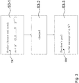
- figure 3 is a block diagram showing a schematic representation of communication by identification in the sense of the present invention and therefore represents the new paradigm of communication.
- a receiver site does not explicitly detect the message m selected and sent by a transmitting site indicated by section S3-1, but instead obtains information about whether or not a message m' selected at the receiver site has been sent by the transmitting site and communicated through the channel indicated by section S3-2.
- the change to an alternate form of channel is a crucial point for the present invention, namely the usage of a so-called compound channel CC.
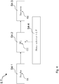
- Figure 4 is a block diagram showing a schematic representation of a compound channel CC in the sense of the present invention.
- Section S4-1 represents the environment of a transmitter or transmitting site TX
- section S4-3 represents the environment of a receiver or receiving site RX.
- the transmitting site TX and the receiving site RX are connected by a so-called compound channel CC which is represented by section S4-2 and comprises a set or family of concrete channels which are selectable by the action of a state selector represented by section S4-2, wherein each state t of a given set ⁇ of states defines the selection of the concrete channel of the compound channel CC.
- the transmission of a selected message or a coat thereof through the compound channel CC is characterized by the channels transmission function W t which is formed by a stochastic matrix.
- Figure 5 is a block diagram showing a schematic representation of a compound wiretap channel WC in the sense of the present invention.
- the configuration shown in figure 5 corresponds to the configuration shown in figure 4 , i.e. sections S5-1, S5-2, S5-3, and S5-4 of figure 5 directly correspond to respective sections S4-1, S4-2, S4-3, and S4-4 of the configuration shown in figure 4 .
- the goal of a receiver is changed compared to direct message transmissions.
- the goal of a receiver of section S2-3 was to decode the transmitted message as such from a transmitting site in section S2-1 and received via a channel in section S2-2 as shown in figure 2 .
- a receiver RX in section S2-3 must be capable of successfully decoding all the messages from a sender or transmitter TX in section S2-1.
- a receiver RX has to decide, based on the information obtained via a channel situated in section S3-2, whether or not the message transmitted by a transmitter TX is equal to an arbitrarily selected message of the message set, as demonstrated in figure 3 .
- the receiver's answer should be correct with high probability.
- Machine-to-machine and human-to-machine communications are centrally important to future communication systems. These new applications demand a strict adherence to end-to-end latency.
- the transmitter TX measures physical and technical variables and sends corresponding data to a receiver (for example, a control center) for evaluation.
- a receiver for example, a control center
- a large part of the possible measured values is not critical for the system behavior as long as the corresponding measured values are in an uncritical range.
- the receiver RX does not have to be able to decode/process the values.
- the receiver is only interested if the values are in a critical range. He only wants to decode/process these critical values.
- the essential point is that the transmitter TX does not need to have any global knowledge about what values are important to the receiver RX (for example the control center). The importance of what values are actually important can change during the operation of the technical system. Such situations occur in the above-mentioned applications.
- identification with channel uncertainty is considered. This is modeled by a given set of channels. The communication participants know this set, but they do not know which channel of this set describes the channel actual used. This can be caused, for example, by a time change or by an inaccurate estimate of the channel. This can also be considered as a channel with state selector.
- a state selector S4-4, S5-4 chooses a channel, but the transmitter TX and the receiver RX do not know his selection.
- Such a model is called a compound channel and may be denoted by CC.
- a (n, N, ⁇ ) identification code for the compound channel
- M 1 , 2 , ... , M of the transmission code
- Figure 4 shows an example of a compound channel CC.
- the 1 st problem is extended by an eavesdropper or wiretapper WT.
- It is called a wiretap channel and may be denoted by WC.
- It is defined by a common input alphabet and possibly different output alphabets, connecting a sender with two receivers, one legal receiver RX and one wiretapper WT.
- the legitimate receiver RX accesses the output of the 1 st channel and the wiretapper WT observes the output of the 2 nd channel.
- a code for the channel conveys information to the legal receiver RX such that the wiretapper WT knows nothing about the transmitted information.
- a state selector chooses a state t, but the transmitter TX and the receiver RX do not know his selection. Now the wiretapper WT gets the selected state t.
- a (n, N, ⁇ ) identification code for the compound wiretap channel also denoted by CWC
- Each coloring corresponds to an identification message.
- the transmitter TX chooses one coloring, let's say T i , and a message of the message set M' , let's say m at random. Then he calculates the color of the message m under T i and transmits both the message m with the 1 st fundamental code and the color of the message m under T i with the 2 nd fundamental code.
- the receiver RX interested in identification message i' calculates the color of the message m under T i' and checks whether it is equal to the received color or not. In the 1 st case, it is decided that the original identification message was i', otherwise he says it was not i'.
- a wiretap code is used for the 2 nd fundamental code with the strong secrecy criterion. It is thus not possible for the wiretapper WT to identify the message.
- Figure 5 shows the compound wiretap channel CWC.
- the communication task of identification was introduced in by R. Ahlswede and G. Dueck.
- the compound channel model was introduced by Blackwell, Breiman, and Thomasian.
- the degraded form of the wiretap channel was introduced by Wyner. The non-degraded model can be solved.
- the compound channel CC is considered. This model models both lack of knowledge of the channel and possible attacks by an attacker. The lack of knowledge of the channel occurs when the channels can only be estimated in real communication systems. Pilot signals are used for this purpose.
- the probability for a sequence y n ⁇ Y n to be received if x n ⁇ X n was sent and t ⁇ ⁇ is the state defined by W t n y n
- the compound Channel CC works as follows: Before the sender TX transmits x n over the channel, t ⁇ ⁇ is chosen by the state selector and W t is used during the transmission.
- a suitable code-concept for transmitting messages over a given compound channel CC is defined.
- a randomized (n, M, ⁇ )-transmission code for a compound channel CC with ( W t ) t ⁇ ⁇ is a family of pairs Q i D i
- wiretap channel WC is considered in the following.
- x : x ⁇ X , y ⁇ Y is the channel transmission matrix, whose output is available to the legitimate receiver RX, and V V z
- the (message transmission) secrecy capacity Cs(W, V) of the wiretap channel WC is defined as the maximum rate of any code which satisfies these conditions.
- M S n ⁇ max M : ⁇ an n M ⁇ WC ⁇ code
- a randomized (n, M, ⁇ 1 , ⁇ 2 ) i identification code for the DMC is a family of pairs Q i D i
- x n ⁇ 1 ⁇ ⁇ 1 , ⁇ i 1 , ... , N and ⁇ x ⁇ X n Q j x n W n D i
- x n ⁇ ⁇ 2 , ⁇ i , j 1 , ... , M , i ⁇ j .
- the receiver RX which is interested in message i will decide that his message was transmitted if and only if the received channel output is in , otherwise the receiver RX will deny that message i was sent.
- Errors of the 1 st kind are produced by channel noise, while on the other hand errors of the 2 nd kind are mainly created by the identification code scheme.
- M ID n N ⁇ : max ⁇ N ⁇ N : A n N ⁇ 1 ⁇ 2 ID code exists with ⁇ 1 , ⁇ 2 ⁇ ⁇ .
- Definition 7 Let ( , , W ) be a DMC.
- a randomized (n, N, ⁇ ) wiretap channel identification code for the wiretap channel WC is a system Q i D i : 1 ⁇ i ⁇ N where, for all i, Q i ⁇ P X n and D i ⁇ Y n , which satisfies the following three conditions:
- the protocol for identification with an eavesdropper uses a wiretap code with a weak secrecy condition.
- the strong secrecy condition requires the total information transfer to the eavesdropper to tend to zero
- the weak secrecy condition requires the per-symbol information transfer to go to zero.
- the strong secrecy condition guaranteed more security. Therefore, it is more suitable to use the strong secrecy condition, when one can reach the same capacity as with the weaker one.
- the present invention inter alia considers robust identification codes and secure robust identification codes.
- Definition 11 Let ( , , ) be a compound channel CC.
- the core of the proof is a result achieved on hypergraphs.
- ⁇ may be called e-uniform, if all its edges E have cardinality e.
- An edge E ⁇ E denotes the characteristic function of E ⁇ V by 1 E .
- the identification capacity C ID of a robust channel model i.e. of the compound channel CC, is determined.
- the channel is assumed to be memoryless.
- the identification capacity of the compound wiretap channel CWC can be given and a secure and robust identification code can be constructed.
- the identification code is constructed by two codes.
- the identification capacity C ID ( ) is positive if the capacity of the wiretap channel WC is positive.
- the 1 st protocol for identification of a message over a robust Channel is developed. This has the advantage that exact channel knowledge is not needed any more. Furthermore, another protocol can be given which is protected against an eavesdropper. It is shown that only a small secrecy capacity of the wiretap channel WC is necessary in order to use the full identification capacity of the channel and to keep the wiretapper WT uninformed.
- an exponential efficiency increase is achieved, as discussed in more detail in section 1.
- This can be considered as a model with a state selector. The selector chooses a state t, but the sender TX and the receiver RX do not know his selection. The wiretapper WT gets the state t. This corresponds to an active attack by the state selector and passive wiretapping. It may be assumed that the wiretapper WT also acts as a state selector. For the construction of the code a code with strong secrecy criterion can be used.
Landscapes
- Engineering & Computer Science (AREA)
- Computer Security & Cryptography (AREA)
- Physics & Mathematics (AREA)
- Probability & Statistics with Applications (AREA)
- Theoretical Computer Science (AREA)
- Computer Hardware Design (AREA)
- Computing Systems (AREA)
- General Engineering & Computer Science (AREA)
- Computer Networks & Wireless Communication (AREA)
- Signal Processing (AREA)
- Communication Control (AREA)
Abstract
Description
- The present invention refers to a method and a system for transmitting and/or receiving messages via identification, in particular in an environment of registered transmitting and receiving sites.
- In the field of transmitting and/or receiving messages by identification the paradigm by Shannon which resides on (i) transmitting a desired message as such from the transmitting site and (ii) detecting the respective message at a receiver site is skipped. Instead, it has been proposed to use the concept of identification for transmitting/receiving messages. In other words, a code representative for a selected message is sent from the transmitting site, and the receiving site is configured to decide whether or not a message selected at the receiving site or a code therefore has been transmitted. By these measures introduced by Ahlswede and Dueck already in 1989, the channel capacity is increased in a double exponential manner.
- It is an object underlying the present invention to improve transmission/receiving of messages by identification in view of its robustness and security aspects.
- The object is achieved by a method and a system of/for transmitting messages according to
independent claims 1 and 13, respectively. Preferred embodiments are defined in the respective dependent claims. - According to a first aspect of the present invention a method of transmitting and/or receiving messages in an environment of registered transmitting sites and receiving sites via identification is provided. According to the present invention a respective message is selected from a fixed set of messages - which may in particular be finite or at least countable - and which is sent and/or received over a compound channel via identification. In addition according to the present invention, the compound channel - as a set of channels and ruled by a state variable - is given and used based on a compound code by using a stochastic encoder.
- According to a preferred embodiment of the present invention for identifying at a transmitting site a message to be sent and selected from the set of messages an identification code may be used which is generated based on said compound code by using a stochastic encoder.
- This may in both cases be done in order to randomly select at the transmitting site a code for the message selected from the set of messages.
- Additionally or alternatively for re-identifying at a receiving site whether a message corresponding to a code received at the receiving site is identical to a certain message selected from the set of messages at the receiving site an identification code or said identification code mentioned before may be used which is generated based on said compound code by using a stochastic encoder or said stochastic encoder.
- In order to realize a respective stochastic encoder and/or a decoder, a variety of measures may be taken.
- For instance and following a preferred embodiment of the present invention, at a transmitting site for a respective message selected said stochastic encoder may be configured in order to randomly assign thereto as a code for the message a value of a random variable within an assigned probability distribution, and the assigned code may be transmitted via the compound channel.
- Additionally or alternatively, at a receiving site it may be checked whether a respective code received at the receiving site and referred to as a value of a random variable is within a probability distribution assigned to a respective message selected at the receiving site.
- Under such circumstances, it may be recognized (i) that the respective message selected at the receiving site has been sent by a transmitting site and otherwise (ii) that the respective message has not been sent by the transmitting site. Thereby, the identification paradigm is realized in contrast to the channel in principle of identifying the sent message as such.
- According to the present invention provable security can be achieved.
- In order to gain such an object it is preferred that at a transmitting site a channel quality of a respective individual channel of the compound channel or of the compound channel in its entirety is monitored, in particular by observing the mutual information or trans-information between individual channels for a dedicated receiving site and individual channels for a non-dedicated receiving site, for a wiretapper entity and/or by deriving therefrom a representative channel security parameter.
- In the following the notions non-dedicated receiving site, non-legitimate receiving site, wiretapper and eavesdropper may be used as synonyms.
- Different physical observables may be used as a basis for deriving a respective channel security parameter.
- According to another preferred embodiment of the present invention, the channel security parameter may be used as a basis for ruling the processing at a transmitting site.
- In particular a process of sending a message selected at a transmitting site may be suppressed and/or postponed in case that the channel security parameter indicates that a secure transmission is not possible.
- According to a further preferred embodiment of the method for transmitting and/or receiving messages, a secrecy transmission capacity may be used as a channel security parameter.
- This parameter may indicate a possible secure transmission in case that it has a value larger than 0.
- Based on the said channel security parameter a stochastic encoder or a set thereof may be chosen at a respective transmitting site.
- Additionally or alternatively, a decoder or a set thereof may be chosen at a respective receiving site also based on said channel security parameter, wherein in particular a decoder at a receiving site may be formed according to the specification of a corresponding stochastic encoder at a transmitting site and may be deterministic.
- Additionally or alternatively, a respective encoder and/or a respective decoder may be based on the nature of the compound channel and/or may be based on any one of LDPC codes, polar codes, turbo codes, and raptor codes.
- At a receiving site a decoder may be formed by a family of pairwise non-disjunct decoder sets.
- For securing a message (i) selected at the transmitting site and (ii) to be sent to a dedicated receiving site and its code against wiretapping by wiretapping entities and in particular by not-dedicated receiving sites a wiretap code may be constructed and used.
- This may be done in order to thereby define and transmit at a transmitting site a coloring for the message or its code to be sent.
- It is of particular advantage, if a respective encoder and/or decoder is formed based on a family of code books.
- A respective instance of a code book may be chosen randomly and/or based on a respective channel security parameter as mentioned above.
- The present invention further relates to a system for transmitting and/or receiving messages in an environment of registered transmitting sites and receiving sites via identification. The system is configured in order to perform or in order to be used in a method of transmitting and/or receiving messages in an environment of registered transmitting sites and receiving sites via identification according to the present invention.
- Previously and in the following, a transmitter or transmitting site may be identified with an encoder, whereas a receiver or a receiving site may be identified with a decoder in the sense of the present invention.
- In addition, the notions of probabilistic, random, and stochastic encoders may be used as synonyms in the sense of the present invention.
- Further on, the notions mutual information and trans-information are used as synonyms, too.
- It is inter alia a gist of the present invention to achieve in methods and systems for transmitting and/or receiving messages via identification an improved degree of robustness and security.
- One key measure in order to realize this object - besides the usage of a compound channel - envisages involving a stochastic encoder.
- According to a further aspect of the present invention, the concept of stochastic encoders is used in a threefold manner, namely in order to achieve robustness, to realize identification, and to guarantee secrecy of the transmitted information.
- Using a stochastic encoder means that at least a transmitting site is capable of randomly selecting an element according to a certain distribution.
- (1) For achieving robustness, a stochastic encoder is used in order to generate a compound code. This is necessary as within the concept of compound channel the transmitting site is not capable of knowing which channel within the class of channels defining the compound channel is actually being used.
- (2) For realizing identification, a stochastic encoder is used in order to generate from the compound code an identification code. The stochastic encoder is used in order to randomly choose an element from a given set of elements.
- (3) For guaranteeing secrecy in the process of transmitting and/or receiving messages, a stochastic encoder is used in order to generate the wiretap code. In this manner, the stochastic encoder is used in order to secure a message to be transmitted against wiretappers. The wiretap code is used as a second fundamental code in order to keep the message to be identified secret. This may also be referred as a coloring in connection with the message or its code to be transmitted.
- These and further details, advantages and features of the present invention will be described based on embodiments of the invention and by taking reference to the accompanying figures.
- Figure 1
- is a block diagram elucidating general aspects of the method according to the present invention configured for transmitting and/or receiving a message or in general a data signal.
- Figure 2
- is a block diagram showing a schematic representation of communication in the sense of Shannon with the transmission of a message as such.
- Figure 3
- is a block diagram showing a schematic representation of communication by identification in the sense of the present invention.
- Figure 4
- is a block diagram showing a schematic representation of a compound channel in the sense of the present invention.
- Figure 5
- is a block diagram showing a schematic representation of a compound wiretap channel in the sense of the present invention.
- In the following embodiments and the technical background of the present invention are presented in detail by taking reference to accompanying
figures 1 to 5 . Identical or equivalent elements and elements which act identically or equivalently are denoted with the same reference signs. Not in each case of their occurrence a detailed description of the elements and components is repeated. - The depicted and described features and further properties of the invention's embodiments can arbitrarily be isolated and recombined without leaving the gist of the present invention.
- The scheme according to the block diagram of
figure 1 generally follows the concept of coding/decoding and modulation/demodulation in digital communication proposed in 1974 by Massey. - The scheme of
figure 1 discloses a system T - being it a hardware structure, a configuration of a method or of processing units or a combination thereof - comprising - (i) an information source unit T1 configured to provide a signal U to be converted and transmitted, an
- (ii) encoding unit T2 configured to receive and encode the signal U and to output an encoded signal X,
- (iii) a modulator unit T3 configured to receive and modulate the encoded signal X and to output a modulated signal s(t) for transmission over
- (iv) a transmission/reception waveform channel unit T4,
- (v) a demodulator unit T5 configured to receive the modulated signal s(t) in a form r(t) possibly distorted by the transmission channel unit T4 and to demodulate said signal in order to output a demodulated signal Y,
- (vi) a decoder unit T6 configured to receive and decode the demodulated signal Y and to output the decoded signal V, and
- (vii) an information sink unit T7 configured to receive the decoded signal V.
- Key aspects of the present invention are situated in the encoding unit T2 and decoding unit T6 also to be seen in connection with respective embracing transmitter TX and receiver RX for transmitting and receiving, respectively, data signals and in particular messages or codes therefore.
-
Figure 2 is a block diagram showing a schematic representation of communication in the sense of Shannon with the transmission of a message m as such. -
Figure 2 therefore represents the classical paradigm of communication, wherein in a first section S2-1 of the processing shown infigure 2 a message m is selected from a setof messages such that formally the expression

- In contrast thereto,
figure 3 is a block diagram showing a schematic representation of communication by identification in the sense of the present invention and therefore represents the new paradigm of communication. - As shown in connection with section S3-3, a receiver site does not explicitly detect the message m selected and sent by a transmitting site indicated by section S3-1, but instead obtains information about whether or not a message m' selected at the receiver site has been sent by the transmitting site and communicated through the channel indicated by section S3-2.
- The new scheme of communication by identification
- Besides the change of paradigm from detecting a message sent to detecting whether or not a selected message has been sent, i.e. the change to communication by identification, the change to an alternate form of channel is a crucial point for the present invention, namely the usage of a so-called compound channel CC.
-
Figure 4 is a block diagram showing a schematic representation of a compound channel CC in the sense of the present invention. - Section S4-1 represents the environment of a transmitter or transmitting site TX, whereas section S4-3 represents the environment of a receiver or receiving site RX. The transmitting site TX and the receiving site RX are connected by a so-called compound channel CC which is represented by section S4-2 and comprises a set or family of concrete channels which are selectable by the action of a state selector represented by section S4-2, wherein each state t of a given set θ of states defines the selection of the concrete channel of the compound channel CC. In addition the transmission of a selected message or a coat thereof through the compound channel CC is characterized by the channels transmission function Wt which is formed by a stochastic matrix.
-
Figure 5 is a block diagram showing a schematic representation of a compound wiretap channel WC in the sense of the present invention. - The configuration shown in
figure 5 corresponds to the configuration shown infigure 4 , i.e. sections S5-1, S5-2, S5-3, and S5-4 offigure 5 directly correspond to respective sections S4-1, S4-2, S4-3, and S4-4 of the configuration shown infigure 4 . - In addition, the configuration of
figure 5 for the compound wiretap channel CWC comprises as a non-dedicated or non-legitimate und thus desired receiving site a wiretapper WT in section S5-6 which is connected to the transmitting site TX situated in section S5-1 by means of a wiretap channel WC in section S5-5 and defined by transmission function Vt in the form of a stochastic matrix and dependent on the state selector of section S5-4 and the respective states t ∈ θ = {1,...,T} selected. - These and further aspects of the present invention will also be described in detail in the following, which inter alia additionally relate to general protocols for secure and robust identification via channels.
- Thus, in the context of the present invention, secure and robust protocols for identification of messages over communication channels are considered.
- Accordingly, in the general theory of identification underlying the present invention the goal of a receiver is changed compared to direct message transmissions. In the theory of message transmission, as it has been defined by Shannon, the goal of a receiver of section S2-3 was to decode the transmitted message as such from a transmitting site in section S2-1 and received via a channel in section S2-2 as shown in
figure 2 . - For this kind of communication, a receiver RX in section S2-3 must be capable of successfully decoding all the messages from a sender or transmitter TX in section S2-1.
- In the theory of identification, however, a receiver RX has to decide, based on the information obtained via a channel situated in section S3-2, whether or not the message transmitted by a transmitter TX is equal to an arbitrarily selected message of the message set, as demonstrated in
figure 3 . - The receiver's answer should be correct with high probability.
- Machine-to-machine and human-to-machine communications are centrally important to future communication systems. These new applications demand a strict adherence to end-to-end latency.
- As can be shown, the secrecy for these applications and their necessary latency requirements must be embedded in the physical transmission. Furthermore, for many of the applications discussed, the message transmission problem is too limiting. The theory of identification is not as restrictive at the receiver side like the theory of communication. For this reason, significant performance improvements in communication systems by using implementation of identification codes instead of usual communication codes can be expected.
- In particular, possible promising applications with improvements - among other - are
- communication solutions for industry 4.0,
- communication solutions for logistics applications,
- vehicle-to-vehicle communication,
- vehicle-to-infrastructure communication, and
- infrastructure-to-vehicle communication.
- The future 5G communication system "tactile internet" will be developed for these and other applications. In all of these applications, at least one of the following situations occur: The transmitter TX measures physical and technical variables and sends corresponding data to a receiver (for example, a control center) for evaluation. A large part of the possible measured values is not critical for the system behavior as long as the corresponding measured values are in an uncritical range. In this case, the receiver RX does not have to be able to decode/process the values. The receiver is only interested if the values are in a critical range. He only wants to decode/process these critical values. The essential point is that the transmitter TX does not need to have any global knowledge about what values are important to the receiver RX (for example the control center). The importance of what values are actually important can change during the operation of the technical system. Such situations occur in the above-mentioned applications.
- In the following sections regarding some background and its limitations, the difference between these two conceptual formulations will be considered.
- Two different problems are consider, namely (1) robust identification as such and (2) robust and secure identification on the other hand:
- In the 1st problem, identification with channel uncertainty is considered. This is modeled by a given set of channels. The communication participants know this set, but they do not know which channel of this set describes the channel actual used. This can be caused, for example, by a time change or by an inaccurate estimate of the channel. This can also be considered as a channel with state selector. A state selector S4-4, S5-4 chooses a channel, but the transmitter TX and the receiver RX do not know his selection. Such a model is called a compound channel and may be denoted by CC.
- To construct a (n, N, λ) identification code for the compound channel, a (n, M, λ) transmission code


-
Figure 4 shows an example of a compound channel CC. - In the 2nd problem identification with channel uncertainty and security is considered. The 1st problem is extended by an eavesdropper or wiretapper WT. In practice, this means that the transmitter TX and the recipient or receiver RX do not want other - e.g. hostile - parties to be able to identify the message. It is called a wiretap channel and may be denoted by WC. It is defined by a common input alphabet and possibly different output alphabets, connecting a sender with two receivers, one legal receiver RX and one wiretapper WT. The legitimate receiver RX accesses the output of the 1st channel and the wiretapper WT observes the output of the 2nd channel. A code for the channel conveys information to the legal receiver RX such that the wiretapper WT knows nothing about the transmitted information. This again can be considered as a transmission with a state selector situated in section S5-4 in
figure 5 . As before, a state selector chooses a state t, but the transmitter TX and the receiver RX do not know his selection. Now the wiretapper WT gets the selected state t. - This corresponds to an active attack by the state selector and passive wiretapping. One may assume that the wiretapper WT also acts as a state selector. To construct a (n, N, λ) identification code for the compound wiretap channel also denoted by CWC, one may use two fundamental codes, namely a (n, M', λ) transmission code


- Each coloring corresponds to an identification message. The transmitter TX chooses one coloring, let's say Ti , and a message of the message set M', let's say m at random. Then he calculates the color of the message m under Ti and transmits both the message m with the 1st fundamental code and the color of the message m under Ti with the 2nd fundamental code. The receiver RX interested in identification message i' calculates the color of the message m under Ti' and checks whether it is equal to the received color or not. In the 1st case, it is decided that the original identification message was i', otherwise he says it was not i'. A wiretap code is used for the 2nd fundamental code with the strong secrecy criterion. It is thus not possible for the wiretapper WT to identify the message.
-
Figure 5 shows the compound wiretap channel CWC. - For the above application fields, or generally for the applications mentioned with the tactile internet, already some parts have been standardized or are in the current development/standardization. One example is the 5G wireless communication system. All solutions are based on the communication approach of Shannon (see
figure 2 ), which means that these implementations/standardizations do not even have the structure of the identification task. - This results in an inefficient use of the resources of the communication system (see Section 3, subsection 1). This will also be shown by the representations of the following known scientific results for identification.
- The communication task of identification was introduced in by R. Ahlswede and G. Dueck. The compound channel model was introduced by Blackwell, Breiman, and Thomasian. The degraded form of the wiretap channel was introduced by Wyner. The non-degraded model can be solved.
- According to the present invention, two methods for coding strategies are used.
- Information theoretic models and their achievable rates are considered. Our second model concerned with security. One may use for the envisaged strategy codes with strong secrecy. The definitions of our two models are as follows.
- 1. Firstly, the compound channel CC is considered. This model models both lack of knowledge of the channel and possible attacks by an attacker. The lack of knowledge of the channel occurs when the channels can only be estimated in real communication systems. Pilot signals are used for this purpose.
- Definition 1: A discrete memoryless compound channel CC is a triple(,
 ,
, ), where
 is the finite input alphabet,
 is the finite output alphabet, θ is a finite state set, and


- If it is clear which alphabets are to be used, one may omit them if one is talking about the channel. If P is a probability distribution onand


- The compound Channel CC works as follows: Before the sender TX transmits xn over the channel, t ∈ θ is chosen by the state selector and Wt is used during the transmission. A compound channel CC with /θ/ = 1 is called a discrete memoryless channel, abbreviated by DMC.
- In the following, a suitable code-concept for transmitting messages over a given compound channel CC is defined.
- Definition 2: A randomized (n, M, λ)-transmission code for a compound channel CC with (Wt ) t∈θ is a family of pairs




- The definition MCC (n, M, λ) := max{M : A (n, M, λ) CC code exists} is adopted.
- Definition 3: Let W be a compound channel CC.
- (a) The rate R of an (n, M, λ) code is defined as R = log(M)/n bits.
- (b) A rate R is said to be achievable if for all λ ∈ (0, 1) there exists a n0(λ), such that for all n ≥ n0(λ) there exists a (n, 2nR, λ) code.
- (c) The transmission capacity C() of a compound channel
 is the supremum of all achievable rates.
- The following theorem holds.
- Theorem 1: The capacity of the compound channelis


- 2. Secondly, the wiretap channel WC is considered in the following.
- Definition 4: A discrete memoryless wiretap channel (WC) is a quintuple (,
 ,
, , W, V) wherein
 is the finite input alphabet,
 is the finite output alphabet for the legitimate receiver RX,
 is the finite output alphabet for the wiretapper WT,


- Definition 5: A (n, M, λ) secrecy code for the wiretap channel (,
 ,
, , W, V) is defined as a system


- The (message transmission) secrecy capacity Cs(W, V) of the wiretap channel WC is defined as the maximum rate of any code which satisfies these conditions. Formally, let

s }. - The following property holds:
-

- 3. Thirdly, identification codes are considered in the following.
- Definition 6: A randomized (n, M, λ1, λ2)i identification code for the DMC is a family of pairs


- The receiver RX which is interested in message i will decide that his message was transmitted if and only if the received channel output is in, otherwise the receiver RX will deny that message i was sent.

- Those two error probabilities turn out to be of different nature: Errors of the 1st kind are produced by channel noise, while on the other hand errors of the 2nd kind are mainly created by the identification code scheme.
- Let

- Definition 7: Let (,
 , W) be a DMC.
- (a) The rate R of an (n, N, λ1, λ2) identification code is defined as

- (b) The identification rate R of a DMC is said to be achievable if for all λ ∈ (0, 1) there exists a n0(λ), such that for all n ≥ n0(λ) there exists a (n, 22 nR , λ, λ) identification code.
- (c) The identification capacity CID(W) of a DMC W is the supremum of all achievable rates.
-

- 4. Fourthly, identification over a wiretap channel WC is considered.
- Definition 8: A randomized (n, N, λ) wiretap channel identification code for the wiretap channel WC is a system

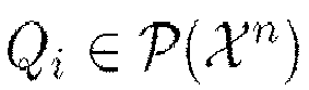

- (a) for all i :

- (b) for all pairs (i, j) with i ≠ j :

- (c) for any pair (i, j) with i ≠ j and any


- Definition 9: The maximum M for which a randomized (n, M, λ) wiretap channel identification code exists is denoted by MSID(n, λ). Define the secure identification capacity CSID of the wiretap channel WC by letting

- A remarkable result on this problem follows.
- Theorem 4: Let C(W) be the Shannon capacity of the channel W and let Cs(W, V) be the secrecy capacity of the wiretap channel WC, then


- Two areas are considered: On the one hand the implementations and on the other hand the scientific results.
- 1. As already described in Section 2 above, all known implementations for solving the problem of identification are based on Shannon's transmission theory. By this limitation, much less messages/events can be identified quantitatively. More specifically, using the protocols based on Shannon's theory, 2 nC messages/events can be transmitted, where C is the capacity of the channel. So based on Shannon's approach only 2nC messages/events can be identified. Using the protocols based on identification theory, 22 nC messages/events can be identified. Therefore, for problems in which messages/events have to be identified, such as those described in
section 1, one should use protocols from the identification theory. This direct implementation has resulted in an extreme increase in efficiency, is the sense of an exponential increase. - 2. The 1st identification protocols were developed by Ahlswede and Dueck in 1989. The 1st identification protocol with safety aspect was developed by Ahlswede and Zhang in 1995. All known protocols for identifications can only be used for non-robust channels. Therefore the channel have to be known exactly. Practically, this is not possible.
- Furthermore, the protocol for identification with an eavesdropper uses a wiretap code with a weak secrecy condition. Whereas the strong secrecy condition requires the total information transfer to the eavesdropper to tend to zero, the weak secrecy condition requires the per-symbol information transfer to go to zero. Obviously, the strong secrecy condition guaranteed more security. Therefore, it is more suitable to use the strong secrecy condition, when one can reach the same capacity as with the weaker one.
- The present invention inter alia considers robust identification codes and secure robust identification codes.
- 1. Firstly, a robust identification code is defined.
- Definition 10: A randomized (n, N, λ 1, λ 2 ) compound channel identification code with states t in a set θ = {1, ..., T} is a family of pairs


- Definition 11: Let (,
 ,
, ) be a compound channel CC.
- (a) The transmission rate R of an (n, N, λ 1 , λ 2 ) compound channel identification code is R = log(log(N)) / n bits.
- (b) The identification rate R of a compound channel CC is said to be achievable if for all λ ∈ (0, 1) there exists a n0(λ), such that for all n ≥ n0(λ) there exists a (n, 22 nR , λ, λ) compound channel identification code.
- (c) The identification capacity

- It can be shown that the errors of the 1st and of the 2nd kind for the construction described in section 1.1 are small. Furthermore, it can be shown that the rate of the protocol is best possible.
- The core of the proof is a result achieved on hypergraphs.
- A hypergraph is a pair


- The identification capacity CID of a robust channel model, i.e. of the compound channel CC, is determined.
- Theorem 5: For the compound channel CC the relation

- 2. Secondly, a secure robust identification code is defined.
- Definition 12: Let θ = {1,..., T} be a finite index set. A discrete memoryless compound wiretap channel , denoted by CWC, is a quintuple (,
 ,
, , W, V), wherein X is the finite input alphabet,
 is the finite output alphabet for the legitimate receiver RX,
 is the finite output alphabet for the wiretapper WT,


- The problem of identification via this channel in the sense of Ahlswede and Dueck can be formulated as follows:
Definition 13: Let θ = {1,...,T},
 ,
, ) be a compound wiretap channel CWC. A randomized


- Definition 14: The maximum M for which a randomized (n, M, λ) compound wiretap channel identification code exists is denoted by MSID(n, λ). Define the secure identification capacity CSID of the compound wiretap channel CWC by

n(R-λ) }. - The identification capacity of the compound wiretap channel CWC can be given and a secure and robust identification code can be constructed.
- Theorem 6: (Dichotomy Theorem) Let CS () be the capacity of a compound channel
 and let
 ,
, ), then


- The identification code is constructed by two codes.
-
Let 0 < ε < C be fixed. There is a δ > 0 such that for sufficiently large n there is an (n, M', λ(n)) compound channel code


- It can be shown that the identification capacity CID () is positive if the capacity of the wiretap channel WC is positive.

- It is clear that the secure identification capacity cannot exceed the identification capacity of the channel. It is enough to show that the secure identification capacity is zero if the message transmission secrecy capacity is zero. Therefore it is shown that

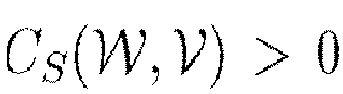
- With the present invention, the 1st protocol for identification of a message over a robust Channel is developed. This has the advantage that exact channel knowledge is not needed any more. Furthermore, another protocol can be given which is protected against an eavesdropper. It is shown that only a small secrecy capacity of the wiretap channel WC is necessary in order to use the full identification capacity of the channel and to keep the wiretapper WT uninformed. By using the theory of identification instead of Shannon's transfer theory, an exponential efficiency increase is achieved, as discussed in more detail in
section 1. This can be considered as a model with a state selector. The selector chooses a state t, but the sender TX and the receiver RX do not know his selection. The wiretapper WT gets the state t. This corresponds to an active attack by the state selector and passive wiretapping. It may be assumed that the wiretapper WT also acts as a state selector. For the construction of the code a code with strong secrecy criterion can be used. - This invention can also be described by the following clauses:
- 1. Method (S) of transmitting and/or receiving messages in an environment of registered transmitting sites (TX) and receiving sites (RX) via identification, wherein:
- a respective message is
- selected from a fixed set of messages - which is in particular finite or countable - and
- sent and/or received over a compound channel (CC) via identification and
- the compound channel (CC) as a set of channels and ruled by a state variable (t) is given and used based on a compound code by using a stochastic encoder.
- a respective message is
- 2. Method (S) according to
clause 1, wherein- for identifying at a transmitting site (TX) a message to be sent and selected from the set of messages and/or
- for re-identifying at a receiving site (RX) whether a message corresponding to a code received at the receiving site (RX) is identical to a certain message selected from the set of messages at the receiving site (RX)
- 3. Method (S) according to any one of the preceding clauses, wherein at a transmitting site (TX)
- for a respective message selected said stochastic encoder is configured to randomly assign thereto as a code for the message a value of a random variable within an assigned probability distribution and
- the assigned code is transmitted via the compound channel (CC).
- 4. Method (S) according to any one of the preceding clauses, wherein at a receiving site
- it is checked whether a respective code received at the receiving site and referred to as a value of a random variable is within a probability distribution assigned to a respective message selected at the receiving site and
- in particular in this case it is recognized (i) that the respective message selected at the receiving site has been sent by a transmitting site and otherwise (ii) that the respective message has not been sent by the transmitting site.
- 5. Method (S) according to any one of the preceding clauses, wherein at a transmitting site (TX)
- a channel quality of a respective individual channel of the compound channel or of the compound channel in its entirety is monitored,
- in particular by observing the mutual information or trans-information between individual channels for a dedicated receiving site (RX) and individual channels for a non-dedicated receiving site, for a wiretapper entity (WT) and/or by deriving therefrom a representative channel security parameter.
- 6. Method (S) according to clause 5, wherein
- the channel security parameter is used as a basis for ruling the processing at a transmitting site (TX) and
- in particular a process of sending a messages selected at a transmitting site is suppressed and/or postponed in case that the channel security parameter indicates that a secure transmission is not possible.
- 7. Method (S) according to clause 6, wherein
- a secrecy transmission capacity is used as a channel security parameter,
- which in particular indicates a possible secure transmission if it has a value larger than 0.
- 8. Method (S) according to any one of clauses 5 to 7, wherein based on the said channel security parameter
- a stochastic encoder or a set thereof is chosen at a respective transmitting site (TX) and/or
- a decoder or a set thereof is chosen at a respective receiving site (RX), wherein in particular a decoder at a receiving site is formed according to the specification of a corresponding stochastic encoder at a transmitting site and/or is deterministic.
- 9. Method (S) according to any one of clauses 5 to 8, wherein
a respective encoder and/or a respective decoder is based on the nature of the compound channel (CC) and/or based on one of LDPC codes, polar codes, turbo codes and raptor codes. - 10. Method (S) according to any one of the preceding clauses,
wherein at a receiving site (RX) a decoder is formed by a family of pairwise non-disjunct decoder sets. - 11. Method (S) according to any one of the preceding clauses,
- wherein for securing a message (i) selected at the sending site and (ii) to be sent to a dedicated receiving site (RX) and its code against wiretapping by wiretapping entities (WT) and in particular by not-dedicated receiving sites a wiretap code is used,
- in particular in order to thereby define and transmit at a transmitting site (TX) a coloring for the message or its code to be sent.
- 12. Method (S) according to any one of the preceding clauses,
wherein a respective encoder and/or decoder is formed based on a family of code books, wherein a respective instance of a code book is chosen randomly and/or based on a respective channel security parameter. - 13. System (T) for transmitting and/or receiving messages in an environment of registered transmitting sites (TX) and receiving sites (RX) via identification,
-
- CC
- compound channel
- CWC
- compound wiretap channel
- IS
- mutual information, trans-information
- r(t)
- sent signal, after physical channel T4 and before demodulator T5
- RX
- receiver, receiving site
- s
- signal to be sent, after modulator T3 and before physical channel T4
- S
- transmission/reception method
- t
- state variable
- T
- transmission/reception system
- T1
- information source unit
- T2
- encoding unit
- T3
- modulator unit
- T4
- (physical) transmission/reception (waveform) channel unit
- T5
- demodulator unit
- T6
- decoder unit
- T7
- information sink unit
- TX
- transmitter, transmitting site, sender
- U
- signal from source T1, before encoder T2
- V
- signal to sink T7, after decoder T6
- WC
- wiretap channel
- WT
- wiretapper
- X
- signal, after encoder T2 and before modulator T3
- Y
- signal, after demodulator T5 and before decoder T6
Claims (1)
- Method (S) of transmitting messages in an environment of transmitters (TX) and receivers (RX) for a transmitter (TX) involving a process of identification, comprising:- selecting a message to be sent from a fixed set of messages,- generating a (n, N, λ) identification code based on a compound code by using a stochastic encoder in order to randomly select a code from the compound code for the message to be sent, wherein the stochastic encoder is used in order to generate the identification code from the compound code,- sending (TX) the identification code over a channel, wherein the channel is modelled as a given compound channel (CC) which is formed as a set of channels and is ruled by a state variable t, wherein the state t is not known to the transmitter (TX);wherein two fundamental codes are used to construct the (n, N, λ) identification code for the compound channel, namely a (n, M', λ) transmission code




 wherein a suitable indexed set of colorings of the messages with a relatively small number of colors M" compared to the number of messages which is known both to the sender and the receiver is used for the message set
 wherein each coloring corresponds to an identification message and the transmitter (TX) chooses one coloring Ti and a message m of the message set M', calculates the color of the message m under the one coloring Ti and transmits the message m with the transmission code and the color of the message m under the one coloring Ti with the wiretap code,wherein θ = {1,...,T} is a finite index set and a discrete memoryless compound wiretap channel , denoted by CWC, is a quintuple (,
 ,
, , W, V), wherein
 is the finite input alphabet,
 is the finite output alphabet for the legitimate receiver (RX),
 is the finite output alphabet for the wiretapper (WT),


 wherein (,
 ) describes the CWC and a randomized


Priority Applications (1)
| Application Number | Priority Date | Filing Date | Title |
|---|---|---|---|
| EP21194998.7A EP3937117B1 (en) | 2017-06-23 | 2017-06-23 | Method and system for transmitting and/or receiving messages via identification |
Applications Claiming Priority (2)
| Application Number | Priority Date | Filing Date | Title |
|---|---|---|---|
| EP17177595.0A EP3418970B1 (en) | 2017-06-23 | 2017-06-23 | Method and system for transmitting and/or receiving messages via identification |
| EP21194998.7A EP3937117B1 (en) | 2017-06-23 | 2017-06-23 | Method and system for transmitting and/or receiving messages via identification |
Related Parent Applications (1)
| Application Number | Title | Priority Date | Filing Date |
|---|---|---|---|
| EP17177595.0A Division EP3418970B1 (en) | 2017-06-23 | 2017-06-23 | Method and system for transmitting and/or receiving messages via identification |
Publications (2)
| Publication Number | Publication Date |
|---|---|
| EP3937117A1 true EP3937117A1 (en) | 2022-01-12 |
| EP3937117B1 EP3937117B1 (en) | 2024-05-22 |
Family
ID=59227509
Family Applications (2)
| Application Number | Title | Priority Date | Filing Date |
|---|---|---|---|
| EP17177595.0A Active EP3418970B1 (en) | 2017-06-23 | 2017-06-23 | Method and system for transmitting and/or receiving messages via identification |
| EP21194998.7A Active EP3937117B1 (en) | 2017-06-23 | 2017-06-23 | Method and system for transmitting and/or receiving messages via identification |
Family Applications Before (1)
| Application Number | Title | Priority Date | Filing Date |
|---|---|---|---|
| EP17177595.0A Active EP3418970B1 (en) | 2017-06-23 | 2017-06-23 | Method and system for transmitting and/or receiving messages via identification |
Country Status (1)
| Country | Link |
|---|---|
| EP (2) | EP3418970B1 (en) |
-
2017
- 2017-06-23 EP EP17177595.0A patent/EP3418970B1/en active Active
- 2017-06-23 EP EP21194998.7A patent/EP3937117B1/en active Active
Non-Patent Citations (2)
| Title |
|---|
| AHLSWEDE R ET AL: "Identification via wiretap channels", INFORMATION THEORY, 1994. PROCEEDINGS., 1994 IEEE INTERNATIONAL SYMPOS IUM ON TRONDHEIM, NORWAY 27 JUNE-1 JULY 1994, NEW YORK, NY, USA,IEEE, 27 June 1994 (1994-06-27), pages 352, XP010135016, ISBN: 978-0-7803-2015-4, DOI: 10.1109/ISIT.1994.394666 * |
| RUDOLF AHLSWEDE ET AL: "Identification via Channels", IEEE TRANSACTIONS ON INFORMATION TH, IEEE PRESS, USA, vol. 198901, 1 January 1989 (1989-01-01), pages 15 - 29, XP007913244, ISSN: 0018-9448 * |
Also Published As
| Publication number | Publication date |
|---|---|
| EP3418970A1 (en) | 2018-12-26 |
| EP3418970B1 (en) | 2021-09-08 |
| EP3937117B1 (en) | 2024-05-22 |
Similar Documents
| Publication | Publication Date | Title |
|---|---|---|
| Ahlswede et al. | Transmission, identification and common randomness capacities for wire-tape channels with secure feedback from the decoder | |
| Boche et al. | Secure identification for wiretap channels; robustness, super-additivity and continuity | |
| Şaşoğlu et al. | A new polar coding scheme for strong security on wiretap channels | |
| Scarlett et al. | Information-theoretic foundations of mismatched decoding | |
| Polyanskiy et al. | Feedback in the non-asymptotic regime | |
| Arumugam et al. | Embedding covert information in broadcast communications | |
| Boche et al. | Secure identification under passive eavesdroppers and active jamming attacks | |
| Boche et al. | Capacity results and super-activation for wiretap channels with active wiretappers | |
| Boche et al. | Secure and robust identification via classical-quantum channels | |
| CN106254072A (en) | A kind of quantum key distribution system and method | |
| Schaefer et al. | Robust broadcasting of common and confidential messages over compound channels: Strong secrecy and decoding performance | |
| Laourine et al. | The degraded Poisson wiretap channel | |
| Wiese et al. | Secure estimation for unstable systems | |
| Janda et al. | Arbitrarily varying wiretap channels with non-causal side information at the jammer | |
| Boche et al. | Classical-quantum arbitrarily varying wiretap channel: Common randomness assisted code and continuity | |
| Bounhar et al. | Mixing a covert and a non-covert user | |
| Aggarwal et al. | Wiretap channel type II with an active eavesdropper | |
| Frey et al. | The MAC resolvability region, semantic security and its operational implications | |
| Tahmasbi et al. | Learning an adversary’s actions for secret communication | |
| Boche et al. | Secure identification under jamming attacks | |
| Zhang et al. | Coding against a limited-view adversary: The effect of causality and feedback | |
| EP3937117B1 (en) | Method and system for transmitting and/or receiving messages via identification | |
| Boche et al. | On arbitrarily varying wiretap channels for different classes of secrecy measures | |
| Zhang et al. | Covert identification over binary-input discrete memoryless channels | |
| Boche et al. | Algorithmic detection of adversarial attacks on message transmission and ACK/NACK feedback |
Legal Events
| Date | Code | Title | Description |
|---|---|---|---|
| PUAI | Public reference made under article 153(3) epc to a published international application that has entered the european phase |
Free format text: ORIGINAL CODE: 0009012 |
|
| STAA | Information on the status of an ep patent application or granted ep patent |
Free format text: STATUS: THE APPLICATION HAS BEEN PUBLISHED |
|
| AC | Divisional application: reference to earlier application |
Ref document number: 3418970 Country of ref document: EP Kind code of ref document: P |
|
| AK | Designated contracting states |
Kind code of ref document: A1 Designated state(s): AL AT BE BG CH CY CZ DE DK EE ES FI FR GB GR HR HU IE IS IT LI LT LU LV MC MK MT NL NO PL PT RO RS SE SI SK SM TR |
|
| B565 | Issuance of search results under rule 164(2) epc |
Effective date: 20211105 |
|
| STAA | Information on the status of an ep patent application or granted ep patent |
Free format text: STATUS: REQUEST FOR EXAMINATION WAS MADE |
|
| 17P | Request for examination filed |
Effective date: 20220712 |
|
| RBV | Designated contracting states (corrected) |
Designated state(s): AL AT BE BG CH CY CZ DE DK EE ES FI FR GB GR HR HU IE IS IT LI LT LU LV MC MK MT NL NO PL PT RO RS SE SI SK SM TR |
|
| RIC1 | Information provided on ipc code assigned before grant |
Ipc: H04L 9/40 20220101ALI20231117BHEP Ipc: H03M 13/29 20060101ALI20231117BHEP Ipc: H03M 13/11 20060101ALI20231117BHEP Ipc: H03M 13/13 20060101ALI20231117BHEP Ipc: H03M 13/35 20060101ALI20231117BHEP Ipc: H03M 13/37 20060101ALI20231117BHEP Ipc: G06T 1/00 20060101AFI20231117BHEP |
|
| GRAP | Despatch of communication of intention to grant a patent |
Free format text: ORIGINAL CODE: EPIDOSNIGR1 |
|
| STAA | Information on the status of an ep patent application or granted ep patent |
Free format text: STATUS: GRANT OF PATENT IS INTENDED |
|
| INTG | Intention to grant announced |
Effective date: 20240108 |
|
| GRAS | Grant fee paid |
Free format text: ORIGINAL CODE: EPIDOSNIGR3 |
|
| GRAA | (expected) grant |
Free format text: ORIGINAL CODE: 0009210 |
|
| STAA | Information on the status of an ep patent application or granted ep patent |
Free format text: STATUS: THE PATENT HAS BEEN GRANTED |
|
| AC | Divisional application: reference to earlier application |
Ref document number: 3418970 Country of ref document: EP Kind code of ref document: P |
|
| AK | Designated contracting states |
Kind code of ref document: B1 Designated state(s): AL AT BE BG CH CY CZ DE DK EE ES FI FR GB GR HR HU IE IS IT LI LT LU LV MC MK MT NL NO PL PT RO RS SE SI SK SM TR |
|
| REG | Reference to a national code |
Ref country code: GB Ref legal event code: FG4D |
|
| REG | Reference to a national code |
Ref country code: CH Ref legal event code: EP |
|
| REG | Reference to a national code |
Ref country code: DE Ref legal event code: R081 Ref document number: 602017082222 Country of ref document: DE Owner name: TECHNISCHE UNIVERSITAET MUENCHEN, KOERPERSCHAF, DE Free format text: FORMER OWNER: ANMELDERANGABEN UNKLAR / UNVOLLSTAENDIG, 80297 MUENCHEN, DE |
|
| REG | Reference to a national code |
Ref country code: DE Ref legal event code: R096 Ref document number: 602017082222 Country of ref document: DE |
|
| REG | Reference to a national code |
Ref country code: IE Ref legal event code: FG4D |
|
| REG | Reference to a national code |
Ref country code: LT Ref legal event code: MG9D |
|
| REG | Reference to a national code |
Ref country code: NL Ref legal event code: MP Effective date: 20240522 |
|
| PG25 | Lapsed in a contracting state [announced via postgrant information from national office to epo] |
Ref country code: IS Free format text: LAPSE BECAUSE OF FAILURE TO SUBMIT A TRANSLATION OF THE DESCRIPTION OR TO PAY THE FEE WITHIN THE PRESCRIBED TIME-LIMIT Effective date: 20240922 |
|
| PG25 | Lapsed in a contracting state [announced via postgrant information from national office to epo] |
Ref country code: BG Free format text: LAPSE BECAUSE OF FAILURE TO SUBMIT A TRANSLATION OF THE DESCRIPTION OR TO PAY THE FEE WITHIN THE PRESCRIBED TIME-LIMIT Effective date: 20240522 |
|
| PG25 | Lapsed in a contracting state [announced via postgrant information from national office to epo] |
Ref country code: HR Free format text: LAPSE BECAUSE OF FAILURE TO SUBMIT A TRANSLATION OF THE DESCRIPTION OR TO PAY THE FEE WITHIN THE PRESCRIBED TIME-LIMIT Effective date: 20240522 Ref country code: FI Free format text: LAPSE BECAUSE OF FAILURE TO SUBMIT A TRANSLATION OF THE DESCRIPTION OR TO PAY THE FEE WITHIN THE PRESCRIBED TIME-LIMIT Effective date: 20240522 |
|
| PG25 | Lapsed in a contracting state [announced via postgrant information from national office to epo] |
Ref country code: GR Free format text: LAPSE BECAUSE OF FAILURE TO SUBMIT A TRANSLATION OF THE DESCRIPTION OR TO PAY THE FEE WITHIN THE PRESCRIBED TIME-LIMIT Effective date: 20240823 |
|
| PG25 | Lapsed in a contracting state [announced via postgrant information from national office to epo] |
Ref country code: PT Free format text: LAPSE BECAUSE OF FAILURE TO SUBMIT A TRANSLATION OF THE DESCRIPTION OR TO PAY THE FEE WITHIN THE PRESCRIBED TIME-LIMIT Effective date: 20240923 |
|
| REG | Reference to a national code |
Ref country code: AT Ref legal event code: MK05 Ref document number: 1689368 Country of ref document: AT Kind code of ref document: T Effective date: 20240522 |
|
| PG25 | Lapsed in a contracting state [announced via postgrant information from national office to epo] |
Ref country code: NL Free format text: LAPSE BECAUSE OF FAILURE TO SUBMIT A TRANSLATION OF THE DESCRIPTION OR TO PAY THE FEE WITHIN THE PRESCRIBED TIME-LIMIT Effective date: 20240522 |
|
| PG25 | Lapsed in a contracting state [announced via postgrant information from national office to epo] |
Ref country code: ES Free format text: LAPSE BECAUSE OF FAILURE TO SUBMIT A TRANSLATION OF THE DESCRIPTION OR TO PAY THE FEE WITHIN THE PRESCRIBED TIME-LIMIT Effective date: 20240522 |
|
| PG25 | Lapsed in a contracting state [announced via postgrant information from national office to epo] |
Ref country code: AT Free format text: LAPSE BECAUSE OF FAILURE TO SUBMIT A TRANSLATION OF THE DESCRIPTION OR TO PAY THE FEE WITHIN THE PRESCRIBED TIME-LIMIT Effective date: 20240522 |
|
| PG25 | Lapsed in a contracting state [announced via postgrant information from national office to epo] |
Ref country code: PL Free format text: LAPSE BECAUSE OF FAILURE TO SUBMIT A TRANSLATION OF THE DESCRIPTION OR TO PAY THE FEE WITHIN THE PRESCRIBED TIME-LIMIT Effective date: 20240522 |
|
| PG25 | Lapsed in a contracting state [announced via postgrant information from national office to epo] |
Ref country code: LV Free format text: LAPSE BECAUSE OF FAILURE TO SUBMIT A TRANSLATION OF THE DESCRIPTION OR TO PAY THE FEE WITHIN THE PRESCRIBED TIME-LIMIT Effective date: 20240522 |
|
| PG25 | Lapsed in a contracting state [announced via postgrant information from national office to epo] |
Ref country code: PT Free format text: LAPSE BECAUSE OF FAILURE TO SUBMIT A TRANSLATION OF THE DESCRIPTION OR TO PAY THE FEE WITHIN THE PRESCRIBED TIME-LIMIT Effective date: 20240923 Ref country code: PL Free format text: LAPSE BECAUSE OF FAILURE TO SUBMIT A TRANSLATION OF THE DESCRIPTION OR TO PAY THE FEE WITHIN THE PRESCRIBED TIME-LIMIT Effective date: 20240522 Ref country code: NO Free format text: LAPSE BECAUSE OF FAILURE TO SUBMIT A TRANSLATION OF THE DESCRIPTION OR TO PAY THE FEE WITHIN THE PRESCRIBED TIME-LIMIT Effective date: 20240822 Ref country code: NL Free format text: LAPSE BECAUSE OF FAILURE TO SUBMIT A TRANSLATION OF THE DESCRIPTION OR TO PAY THE FEE WITHIN THE PRESCRIBED TIME-LIMIT Effective date: 20240522 Ref country code: LV Free format text: LAPSE BECAUSE OF FAILURE TO SUBMIT A TRANSLATION OF THE DESCRIPTION OR TO PAY THE FEE WITHIN THE PRESCRIBED TIME-LIMIT Effective date: 20240522 Ref country code: IS Free format text: LAPSE BECAUSE OF FAILURE TO SUBMIT A TRANSLATION OF THE DESCRIPTION OR TO PAY THE FEE WITHIN THE PRESCRIBED TIME-LIMIT Effective date: 20240922 Ref country code: HR Free format text: LAPSE BECAUSE OF FAILURE TO SUBMIT A TRANSLATION OF THE DESCRIPTION OR TO PAY THE FEE WITHIN THE PRESCRIBED TIME-LIMIT Effective date: 20240522 Ref country code: GR Free format text: LAPSE BECAUSE OF FAILURE TO SUBMIT A TRANSLATION OF THE DESCRIPTION OR TO PAY THE FEE WITHIN THE PRESCRIBED TIME-LIMIT Effective date: 20240823 Ref country code: FI Free format text: LAPSE BECAUSE OF FAILURE TO SUBMIT A TRANSLATION OF THE DESCRIPTION OR TO PAY THE FEE WITHIN THE PRESCRIBED TIME-LIMIT Effective date: 20240522 Ref country code: ES Free format text: LAPSE BECAUSE OF FAILURE TO SUBMIT A TRANSLATION OF THE DESCRIPTION OR TO PAY THE FEE WITHIN THE PRESCRIBED TIME-LIMIT Effective date: 20240522 Ref country code: BG Free format text: LAPSE BECAUSE OF FAILURE TO SUBMIT A TRANSLATION OF THE DESCRIPTION OR TO PAY THE FEE WITHIN THE PRESCRIBED TIME-LIMIT Effective date: 20240522 Ref country code: AT Free format text: LAPSE BECAUSE OF FAILURE TO SUBMIT A TRANSLATION OF THE DESCRIPTION OR TO PAY THE FEE WITHIN THE PRESCRIBED TIME-LIMIT Effective date: 20240522 Ref country code: RS Free format text: LAPSE BECAUSE OF FAILURE TO SUBMIT A TRANSLATION OF THE DESCRIPTION OR TO PAY THE FEE WITHIN THE PRESCRIBED TIME-LIMIT Effective date: 20240822 |
|
| PG25 | Lapsed in a contracting state [announced via postgrant information from national office to epo] |
Ref country code: DK Free format text: LAPSE BECAUSE OF FAILURE TO SUBMIT A TRANSLATION OF THE DESCRIPTION OR TO PAY THE FEE WITHIN THE PRESCRIBED TIME-LIMIT Effective date: 20240522 |
|
| PG25 | Lapsed in a contracting state [announced via postgrant information from national office to epo] |
Ref country code: EE Free format text: LAPSE BECAUSE OF FAILURE TO SUBMIT A TRANSLATION OF THE DESCRIPTION OR TO PAY THE FEE WITHIN THE PRESCRIBED TIME-LIMIT Effective date: 20240522 |
|
| PG25 | Lapsed in a contracting state [announced via postgrant information from national office to epo] |
Ref country code: CZ Free format text: LAPSE BECAUSE OF FAILURE TO SUBMIT A TRANSLATION OF THE DESCRIPTION OR TO PAY THE FEE WITHIN THE PRESCRIBED TIME-LIMIT Effective date: 20240522 |
|
| PG25 | Lapsed in a contracting state [announced via postgrant information from national office to epo] |
Ref country code: RO Free format text: LAPSE BECAUSE OF FAILURE TO SUBMIT A TRANSLATION OF THE DESCRIPTION OR TO PAY THE FEE WITHIN THE PRESCRIBED TIME-LIMIT Effective date: 20240522 Ref country code: SK Free format text: LAPSE BECAUSE OF FAILURE TO SUBMIT A TRANSLATION OF THE DESCRIPTION OR TO PAY THE FEE WITHIN THE PRESCRIBED TIME-LIMIT Effective date: 20240522 |
|
| PG25 | Lapsed in a contracting state [announced via postgrant information from national office to epo] |
Ref country code: SK Free format text: LAPSE BECAUSE OF FAILURE TO SUBMIT A TRANSLATION OF THE DESCRIPTION OR TO PAY THE FEE WITHIN THE PRESCRIBED TIME-LIMIT Effective date: 20240522 Ref country code: RO Free format text: LAPSE BECAUSE OF FAILURE TO SUBMIT A TRANSLATION OF THE DESCRIPTION OR TO PAY THE FEE WITHIN THE PRESCRIBED TIME-LIMIT Effective date: 20240522 Ref country code: EE Free format text: LAPSE BECAUSE OF FAILURE TO SUBMIT A TRANSLATION OF THE DESCRIPTION OR TO PAY THE FEE WITHIN THE PRESCRIBED TIME-LIMIT Effective date: 20240522 Ref country code: DK Free format text: LAPSE BECAUSE OF FAILURE TO SUBMIT A TRANSLATION OF THE DESCRIPTION OR TO PAY THE FEE WITHIN THE PRESCRIBED TIME-LIMIT Effective date: 20240522 Ref country code: CZ Free format text: LAPSE BECAUSE OF FAILURE TO SUBMIT A TRANSLATION OF THE DESCRIPTION OR TO PAY THE FEE WITHIN THE PRESCRIBED TIME-LIMIT Effective date: 20240522 |
|
| REG | Reference to a national code |
Ref country code: CH Ref legal event code: PL |
|
| PG25 | Lapsed in a contracting state [announced via postgrant information from national office to epo] |
Ref country code: IT Free format text: LAPSE BECAUSE OF FAILURE TO SUBMIT A TRANSLATION OF THE DESCRIPTION OR TO PAY THE FEE WITHIN THE PRESCRIBED TIME-LIMIT Effective date: 20240522 Ref country code: MC Free format text: LAPSE BECAUSE OF FAILURE TO SUBMIT A TRANSLATION OF THE DESCRIPTION OR TO PAY THE FEE WITHIN THE PRESCRIBED TIME-LIMIT Effective date: 20240522 |
|
| PG25 | Lapsed in a contracting state [announced via postgrant information from national office to epo] |
Ref country code: LU Free format text: LAPSE BECAUSE OF NON-PAYMENT OF DUE FEES Effective date: 20240623 |
|
| REG | Reference to a national code |
Ref country code: DE Ref legal event code: R097 Ref document number: 602017082222 Country of ref document: DE |
|
| PLBE | No opposition filed within time limit |
Free format text: ORIGINAL CODE: 0009261 |
|
| STAA | Information on the status of an ep patent application or granted ep patent |
Free format text: STATUS: NO OPPOSITION FILED WITHIN TIME LIMIT |
|
| PG25 | Lapsed in a contracting state [announced via postgrant information from national office to epo] |
Ref country code: IE Free format text: LAPSE BECAUSE OF NON-PAYMENT OF DUE FEES Effective date: 20240623 |
|
| PG25 | Lapsed in a contracting state [announced via postgrant information from national office to epo] |
Ref country code: SI Free format text: LAPSE BECAUSE OF FAILURE TO SUBMIT A TRANSLATION OF THE DESCRIPTION OR TO PAY THE FEE WITHIN THE PRESCRIBED TIME-LIMIT Effective date: 20240522 Ref country code: BE Free format text: LAPSE BECAUSE OF NON-PAYMENT OF DUE FEES Effective date: 20240630 Ref country code: CH Free format text: LAPSE BECAUSE OF NON-PAYMENT OF DUE FEES Effective date: 20240630 |
|
| 26N | No opposition filed |
Effective date: 20250225 |
|
| REG | Reference to a national code |
Ref country code: BE Ref legal event code: MM Effective date: 20240630 |
|
| PGFP | Annual fee paid to national office [announced via postgrant information from national office to epo] |
Ref country code: DE Payment date: 20250630 Year of fee payment: 9 |
|
| PGFP | Annual fee paid to national office [announced via postgrant information from national office to epo] |
Ref country code: GB Payment date: 20250620 Year of fee payment: 9 |
|
| PGFP | Annual fee paid to national office [announced via postgrant information from national office to epo] |
Ref country code: FR Payment date: 20250627 Year of fee payment: 9 |
|
| PG25 | Lapsed in a contracting state [announced via postgrant information from national office to epo] |
Ref country code: SE Free format text: LAPSE BECAUSE OF FAILURE TO SUBMIT A TRANSLATION OF THE DESCRIPTION OR TO PAY THE FEE WITHIN THE PRESCRIBED TIME-LIMIT Effective date: 20240522 |
|
| PG25 | Lapsed in a contracting state [announced via postgrant information from national office to epo] |
Ref country code: SM Free format text: LAPSE BECAUSE OF FAILURE TO SUBMIT A TRANSLATION OF THE DESCRIPTION OR TO PAY THE FEE WITHIN THE PRESCRIBED TIME-LIMIT; INVALID AB INITIO Effective date: 20170623 |
|
| PG25 | Lapsed in a contracting state [announced via postgrant information from national office to epo] |
Ref country code: CY Free format text: LAPSE BECAUSE OF FAILURE TO SUBMIT A TRANSLATION OF THE DESCRIPTION OR TO PAY THE FEE WITHIN THE PRESCRIBED TIME-LIMIT; INVALID AB INITIO Effective date: 20170623 |
|
| PG25 | Lapsed in a contracting state [announced via postgrant information from national office to epo] |
Ref country code: HU Free format text: LAPSE BECAUSE OF FAILURE TO SUBMIT A TRANSLATION OF THE DESCRIPTION OR TO PAY THE FEE WITHIN THE PRESCRIBED TIME-LIMIT; INVALID AB INITIO Effective date: 20170623 |